JP6490448B2 - Grommet - Google Patents
Grommet Download PDFInfo
- Publication number
- JP6490448B2 JP6490448B2 JP2015037737A JP2015037737A JP6490448B2 JP 6490448 B2 JP6490448 B2 JP 6490448B2 JP 2015037737 A JP2015037737 A JP 2015037737A JP 2015037737 A JP2015037737 A JP 2015037737A JP 6490448 B2 JP6490448 B2 JP 6490448B2
- Authority
- JP
- Japan
- Prior art keywords
- grommet
- hole
- temporary mounting
- diameter
- frustum
- Prior art date
- Legal status (The legal status is an assumption and is not a legal conclusion. Google has not performed a legal analysis and makes no representation as to the accuracy of the status listed.)
- Active
Links
- 238000005096 rolling process Methods 0.000 claims description 18
- 230000000452 restraining effect Effects 0.000 claims description 3
- 238000000034 method Methods 0.000 description 15
- 229920001971 elastomer Polymers 0.000 description 3
- 238000003780 insertion Methods 0.000 description 3
- 230000037431 insertion Effects 0.000 description 3
- 239000002184 metal Substances 0.000 description 2
- 230000001629 suppression Effects 0.000 description 2
- 230000007423 decrease Effects 0.000 description 1
- 238000010586 diagram Methods 0.000 description 1
- 230000000694 effects Effects 0.000 description 1
- 239000000806 elastomer Substances 0.000 description 1
- 230000035515 penetration Effects 0.000 description 1
Images


Description
この発明は、例えば、車室内とエンジンルームとの間に配置したダッシュパネルを貫通させるワイヤハーネスを保護するグロメットに関する。 The present invention relates to a grommet that protects a wire harness that penetrates a dash panel disposed between a vehicle compartment and an engine room, for example.
例えば、自動車の車室内とエンジンルームとは、ダッシュパネルという金属製のパネルで隔てられているため、車両全体に配索されるワイヤハーネスは、パネルに形成した貫通孔を貫通しなければならない。 For example, since the interior of an automobile and the engine room are separated by a metal panel called a dash panel, the wire harness routed throughout the vehicle must pass through a through-hole formed in the panel.
車体貫通穴に貫通させるワイヤハーネスを金属製のパネルから保護するとともに、車体貫通穴から車室内への水分の浸入を防止する必要があり、止水性を有するとともに、ワイヤハーネスを保護するグロメットが用いられている。 It is necessary to protect the wire harness that penetrates the vehicle body through hole from the metal panel, and to prevent moisture from entering the vehicle interior from the vehicle body through hole, and has a water-tightness and uses a grommet that protects the wire harness It has been.
例えば、特許文献1に記載するような一般的なグロメットは、内部にワイヤハーネスを挿通可能な円筒状であり、車体貫通穴に係止する車体係止溝と、該車体係止溝の両側に配置するとともに、車体貫通穴よりも小径の小径筒部と、該小径筒部から車体係止溝まで拡径する拡径部とで構成し、該拡径部に断面円形で凹状の凹部を備えている。 For example, a general grommet described in Patent Document 1 has a cylindrical shape in which a wire harness can be inserted, and has a vehicle body locking groove that is locked to a vehicle body through hole, and both sides of the vehicle body locking groove. And a small-diameter cylindrical portion having a diameter smaller than that of the vehicle body through-hole and a large-diameter portion that expands from the small-diameter cylindrical portion to the vehicle body locking groove, and the concave portion having a circular cross section and a concave shape is provided in the large-diameter portion. ing.
このようなグロメットの装着方法は、エンジンルームからワイヤハーネスとともにグロメットを車体貫通穴に挿入するとともに、車室内からワイヤハーネスとともにグロメットを引っ張り込むという、パネルで隔てられた両空間を跨いで作業するため、それぞれの空間に1人ずつ作業者を配置して2人で作業するか、両空間を行き来して1人で作業する必要があった。 The grommet is mounted in such a way that the grommet is inserted into the vehicle body through-hole together with the wire harness from the engine room, and the grommet is pulled from the vehicle interior together with the wire harness so as to work across both spaces separated by the panel. It was necessary to place one worker in each space and work by two people, or to move between both spaces and work alone.
この貫通作業を1人で作業する場合、円筒状のグロメットは、作業員がエンジンルームから車室内へ移動する間に、ワイヤハーネスの重さなどで転動して不用意に落下するおそれがあり、装着作業性が悪かった。 When this penetration work is performed by one person, the cylindrical grommet may roll accidentally due to the weight of the wire harness or the like while the worker moves from the engine room to the passenger compartment. The mounting workability was bad.
そこで本発明は、装着作業性を向上させるグロメットを提供することを目的とする。 Then, an object of this invention is to provide the grommet which improves mounting workability | operativity.
この発明は、装着対象箇所の貫通孔よりも大径の大径部と、前記貫通孔よりも小径の小径部と、前記大径部及び前記小径部の間に配置した錐台状の錐台部と、前記大径部及び前記錐台部の間に配置し、前記貫通孔と同程度の径の溝状の溝部とを、軸方向に沿って配置した筒状のグロメットであって、装着状態における前記小径部及び前記錐台部を、前記貫通孔を通過して装着される通過部位とし、前記小径部の前記錐台部側に、前記貫通孔に対して前記通過部位を仮装着するとともに、前記軸方向まわりの転動を抑制する転動抑制形状の仮装着部を備えたことを特徴とする。 The present invention relates to a frustum-shaped frustum arranged between a large-diameter portion having a diameter larger than that of the through-hole at a mounting target, a small-diameter portion having a diameter smaller than that of the through-hole, and the large-diameter portion and the small-diameter portion. A cylindrical grommet, which is disposed between the portion, the large diameter portion and the frustum portion, and a groove-like groove portion having the same diameter as the through hole along the axial direction. The small-diameter portion and the frustum portion in the state are used as passage portions to be attached through the through hole, and the passage portion is temporarily attached to the through-hole on the frustum portion side of the small diameter portion. In addition, a temporary mounting portion having a rolling restraining shape that restrains rolling around the axial direction is provided.
上記装着対象箇所とは、例えば、エンジンルームと車室内とを隔てるダッシュパネルやドアパネルなどの各種パネルを含む概念である。
上記転動抑制形状とは、例えば、2点以上で貫通孔に点接触して転動することを抑制する形状、或いは、貫通孔と同径の円弧状に形成した円弧形状などを含む概念である。
上記仮装着部とは、通過部位の外径を、内側に窪んだ凹状の仮装着部、外側に突出した仮装着部、或いは、通過部位の外面がパネルと面当たりする仮装着部などを含む概念である。
The mounting target location is a concept including various panels such as a dash panel and a door panel that separate the engine room from the vehicle interior.
The rolling suppression shape is a concept including, for example, a shape that suppresses rolling by making point contact with the through hole at two or more points, or an arc shape formed in an arc shape having the same diameter as the through hole. is there.
The temporary mounting portion includes a concave temporary mounting portion that is recessed inwardly, a temporary mounting portion that protrudes outward, or a temporary mounting portion where the outer surface of the passing portion touches the panel. It is a concept.
この発明により、グロメットの装着作業性を向上させることができる。
詳述すると、グロメットに、転動抑制形状の仮装着部を備えたことにより、貫通孔に対して安定してグロメットを装着することができる。
According to the present invention, the grommet mounting workability can be improved.
More specifically, the grommet can be stably mounted on the through hole by providing the grommet with a temporary mounting portion having a rolling restraining shape.
従って、仮装着状態において、ワイヤハーネスの重さなどでグロメットが不用意に転動することを抑制し、安定した仮装着状態を保持することができるため、グロメットの装着作業性を向上させることができる。 Therefore, in the temporary mounting state, the grommet can be prevented from rolling carelessly due to the weight of the wire harness, and the stable temporary mounting state can be maintained, so that the grommet mounting workability can be improved. it can.
この発明の態様として、前記仮装着部を、前記軸方向に沿った平面状のフラット面で構成することができる。
上記軸方向に沿った平面状のフラット面とは、軸方向に交差する幅方向及び軸方向に沿った平行な平面状のフラット面のみならず、上記幅方向に沿っていれば軸方向に交差する方向に沿ったフラット面を含む概念である。
As an aspect of the present invention, the temporary mounting portion can be configured by a flat flat surface along the axial direction.
The planar flat surface along the axial direction means not only the width direction intersecting the axial direction and the parallel planar flat surface along the axial direction, but also intersecting the axial direction if the width direction is met. It is a concept that includes a flat surface along the direction of movement.
この発明により、仮装着状態のグロメットが不用意に転動することを確実に抑制できる。
詳述すると、グロメットに、仮装着部をフラット面で構成したことにより、仮装着状態において、パネルに設けた貫通孔に2点で点接触するため、ワイヤハーネスの重さなどでグロメットが不用意に転動することを確実に抑制できる。従って、グロメットの装着作業性を確実に向上させることができる。
By this invention, it can suppress reliably that the grommet of a temporary mounting state rolls carelessly.
In detail, because the temporary mounting part of the grommet is configured with a flat surface, the grommet is not prepared due to the weight of the wire harness, etc., since the point contact is made at two points with the through hole provided in the panel in the temporary mounting state. Can be reliably suppressed. Therefore, the grommet mounting workability can be improved reliably.
またこの発明の態様として、前記仮装着部を、前記通過部位の外面を凹状に形成した凹部で構成することができる。
この発明により、仮装着状態のグロメットが転動することを抑制できるとともに、グロメットが貫通孔から抜け出ることを防止できる。
As an aspect of the present invention, the temporary mounting portion can be constituted by a concave portion in which the outer surface of the passage portion is formed in a concave shape.
According to the present invention, it is possible to prevent the temporarily attached grommet from rolling, and to prevent the grommet from coming out of the through hole.
詳述すると、仮装着部を、通過部位の外面を凹状に形成した凹部で構成したことにより、上述したフラット面と同様に、凹部の底面が、パネルに設けた貫通孔に2点で点接触するため、ワイヤハーネスの重さなどで不用意に転動することを確実に抑制できる。 More specifically, the temporary mounting portion is constituted by a concave portion in which the outer surface of the passage portion is formed in a concave shape, so that the bottom surface of the concave portion is point-contacted at two points with the through-hole provided in the panel in the same manner as the flat surface described above. Therefore, inadvertent rolling due to the weight of the wire harness can be reliably suppressed.
さらに、ワイヤハーネスの重さなどによってグロメットの抜け出し方向への外力が作用したとしても、凹部の側面が貫通孔に引っ掛かり、グロメットが貫通孔から抜け出ることを防止できる。
従って、安定したグロメットの仮装着状態を確実に保持することができ、グロメットが不用意に転動する、或いはグロメットの抜け出し方向の抜け出しを防止して、作業性をより確実に向上させることができる。
Furthermore, even if an external force in the direction in which the grommet is pulled out acts due to the weight of the wire harness or the like, the side surface of the recess can be caught in the through hole, and the grommet can be prevented from coming out of the through hole.
Therefore, the stable temporary mounting state of the grommet can be reliably held, and the grommet can be inadvertently rolled or the grommet can be prevented from being pulled out in the pulling out direction, thereby improving the workability more reliably. .
またこの発明の態様として、前記仮装着部を、前記小径部と前記錐台部とに跨いで形成することができる。
この発明により、グロメットを貫通孔に対して容易に案内できるとともに、グロメットの安定した仮装着状態を得ることができる。
Further, as an aspect of the present invention, the temporary mounting portion can be formed across the small diameter portion and the frustum portion.
According to the present invention, the grommet can be easily guided with respect to the through hole, and a stable temporary mounting state of the grommet can be obtained.
詳述すると、凹状の仮装着部を、小径部よりも徐々に拡径する錐台部と、小径部とに跨いで形成したことにより、仮装着部の錐台部側の側面は、小径部よりも大径となるため、グロメットを貫通孔に対して仮装着する際に、仮装着部の錐台部側の側面を装着対象箇所に突き当てるだけで、貫通孔に仮装着部を案内することができる。
これにより、仮装着状態のグロメットが、不用意に転動することを抑制できる。
More specifically, the side surface on the frustum portion side of the temporary mounting portion is formed by forming the concave temporary mounting portion straddling the frustum portion gradually expanding from the small diameter portion and the small diameter portion. Therefore, when temporarily attaching the grommet to the through-hole, the temporary attachment portion is guided to the through-hole simply by abutting the side surface of the temporary attachment portion on the frustum portion side against the attachment target location. be able to.
Thereby, it can suppress that the grommet of a temporary mounting state rolls carelessly.
さらに、大径に形成した仮装着部の錐台部側の側面により、グロメットの抜け出し方向への抜け出しを防止できる。
従って、グロメットの装着作業性をより向上させることができる。
Further, the side face on the frustum portion side of the temporary mounting portion formed with a large diameter can prevent the grommet from slipping out in the pulling out direction.
Therefore, the grommet mounting workability can be further improved.
またこの発明の態様として、前記小径部に、先端から前記錐台部に向けて凹状に形成したスリットを備え、前記仮装着部を、前記スリットの基端部に配置することができる。
この発明により、グロメットの損傷を防止できる。
As an aspect of the present invention, the small-diameter portion may include a slit formed in a concave shape from the distal end toward the frustum portion, and the temporary mounting portion may be disposed at the proximal end portion of the slit.
This invention can prevent the grommet from being damaged.
詳述すると、ワイヤハーネスは、仕様などによってワイヤハーネス径が異なるが、グロメットにスリットを備えたことで、小径部の内径よりも大径のワイヤハーネスに対しては、小径部を広げてワイヤハーネスを挿通することができ、小径部の内径よりも小径のワイヤハーネスに対しては、挿通したワイヤハーネスに密着するように小径部を狭めて固定することができる。 Specifically, the wire harness diameter varies depending on the specifications, etc., but the grommet is provided with a slit, so that the wire harness having a larger diameter than the inner diameter of the smaller diameter portion can be widened. The wire harness having a diameter smaller than the inner diameter of the small diameter portion can be fixed by narrowing the small diameter portion so as to be in close contact with the inserted wire harness.
さらに、仮装着部をスリットの基端部に配置したことにより、仮装着部は、上述のように、小径部の内径よりも大径のワイヤハーネスをグロメットに挿通する場合に、スリットの基端部が裂けてグロメットが損傷することを防止できる。 Furthermore, by arranging the temporary mounting portion at the base end portion of the slit, the temporary mounting portion can be inserted into the grommet when the wire harness having a diameter larger than the inner diameter of the small diameter portion is inserted as described above. It is possible to prevent the grommet from being damaged by tearing the part.
さらにまた、スリットとは異なる周方向の位置に仮装着部を形成した場合における形成箇所の薄肉化を防止できるため、貫通孔に装着する際の挿入力が作用してもグロメットが損傷することを防止できる。 Furthermore, since the provisional mounting portion can be prevented from thinning when the temporary mounting portion is formed at a position in the circumferential direction different from the slit, the grommet is damaged even when the insertion force is applied when mounting to the through hole. Can be prevented.
またこの発明の態様として、前記錐台部に、前記溝部よりも小径かつ径方向の外側に突出し、周方向に所定間隔隔てて配置した複数のリブを備えるとともに、前記リブの径外側面に、前記周方向に沿って形成するとともに、前記径方向に突出する突出部を備え、少なくとも1つの前記リブを、前記周方向における前記仮装着部の反対側に配置することができる。 Further, as an aspect of the present invention, the frustum portion includes a plurality of ribs that are smaller in diameter than the groove portion and project outward in the radial direction, and are arranged at predetermined intervals in the circumferential direction. While forming along the said circumferential direction, the protrusion part which protrudes in the said radial direction is provided, and at least 1 said rib can be arrange | positioned on the opposite side of the said temporary mounting part in the said circumferential direction.
上記周方向における仮装着部の反対側とは、周方向において、仮装着部から中心軸を挟んで対向する対面、つまり、仮装着部に対して180度の位置のみならず、該180度の位置を跨ぐような仮装着部に対して90度から270度の範囲、つまり、中心軸より対面側全体を含む概念であり、より好ましくは、135度と225度の範囲における位置である。 The opposite side of the temporary mounting portion in the circumferential direction refers to the opposite surface across the central axis from the temporary mounting portion in the circumferential direction, that is, not only at a position of 180 degrees with respect to the temporary mounting portion, but also at 180 degrees. It is a concept that includes a range from 90 degrees to 270 degrees with respect to the temporary mounting portion that straddles the position, that is, the entire facing side from the central axis, and more preferably positions in the range of 135 degrees and 225 degrees.
この発明により、グロメットが不用意に転動する、或いはグロメットが貫通孔から抜け出ることをより確実に防止できる。
詳述すると、少なくとも1つのリブを、周方向における仮装着部の反対側に配置したことにより、周方向における仮装着部の反対側を貫通孔にさらに押し込むことで、貫通孔を形成する装着対象箇所に突出部を係止できる。
これにより、グロメットが不用意に転動する、或いは貫通孔から抜け出ることを防止しつつ、着孔に対する仮装着状態をより確実に保持し、作業性を向上させることができる。
According to the present invention, it is possible to more reliably prevent the grommet from rolling carelessly or coming out of the through hole.
More specifically, by mounting at least one rib on the opposite side of the temporary mounting portion in the circumferential direction, the mounting target for forming a through hole by further pushing the opposite side of the temporary mounting portion in the circumferential direction into the through hole The protrusion can be locked at the location.
Thereby, the temporary mounting state with respect to the hole can be more reliably maintained and workability can be improved while preventing the grommet from rolling carelessly or coming out of the through hole.
本発明は、装着作業性を向上させるグロメットを提供することができる。 The present invention can provide a grommet that improves mounting workability.
この発明の一実施形態を、図1から図6を用いて説明する。
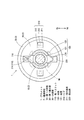
図1は、グロメット1を通過部位2の側からみた斜視図を示し、図2は、グロメット1を非通過部位3の側からみた斜視図を示し、図3は、図1中のA−A矢視断面図を示し、図4は、図1中のB−B矢視断面図を示している。
図5は、第1仮装着工程完了後の断面図を示し、図6は、第2仮装着工程完了後の断面図を示し、図7は、仮装着解除工程完了後の断面図を示し、図8は、装着工程完了の断面図を示している。
An embodiment of the present invention will be described with reference to FIGS.
1 shows a perspective view of the grommet 1 as viewed from the
FIG. 5 shows a cross-sectional view after completion of the first temporary mounting step, FIG. 6 shows a cross-sectional view after completion of the second temporary mounting step, FIG. 7 shows a cross-sectional view after completion of the temporary mounting release step, FIG. 8 shows a cross-sectional view of the completion of the mounting process.
なお、図1から図4においては、グロメット1の内部に挿通したワイヤハーネスWHを透過状態で図示し、図5から図8においては、ワイヤハーネスWHを省略してグロメット1及びダッシュパネル60のみを図示している。
1 to 4, the wire harness WH inserted through the grommet 1 is shown in a transparent state. In FIGS. 5 to 8, the wire harness WH is omitted and only the grommet 1 and the
グロメット1は、自動車のエンジンルームと車室内とを隔てるダッシュパネル60を貫通して配索するワイヤハーネスWHを保護するものであって、ゴムで略円筒状に構成されており、図1から図4に示すように、ワイヤハーネスWHを囲繞しながら、ダッシュパネル60のパネル孔61に対して装着して、ダッシュパネル60のエッジからワイヤハーネスWHを保護するとともに、パネル孔61を通って車室内に水分が浸入することを防止している。
The grommet 1 protects the wire harness WH routed through the
このグロメット1は、図1及び図2に示すように、ワイヤハーネスWHを囲繞可能に軸方向Xに連続する筒状に形成されており、パネル孔61に装着する際に、パネル孔61を通過する通過部位2と、パネル孔61を通過しない非通過部位3と、パネル孔61に装着した状態において、パネル孔61に配置される凹状の溝部4とで構成している。
As shown in FIGS. 1 and 2, the grommet 1 is formed in a cylindrical shape that is continuous in the axial direction X so as to surround the wire harness WH, and passes through the
ここで、理解を容易にするために、軸方向Xのうち、通過部位2側を先端Xaとし、非通過部位3側を基端Xbとする。さらに、グロメット1をパネル孔61に装着した状態における車両の上下方向における上側を車両上側Huとし、車両の下側を車両下側Hdとする(図3から図8を参照)。
Here, in order to facilitate understanding, in the axial direction X, the passing
通過部位2は、図3に示すように、先端Xaから順に、パネル孔61よりも小径に形成した円筒状の第1小径部10と、基端Xbに向けて徐々に拡径する円錐台状の第1錐台部20とで構成している。
As shown in FIG. 3, the
非通過部位3は、先端Xaから順に、パネル孔61よりも大径に形成した円盤状の大径部30と、基端Xbに向けて徐々に縮径する円錐台状の第2錐台部40と、及びパネル孔61よりも小径に形成した円筒状の第2小径部50とで構成している。
溝部4は、パネル孔61と同程度の径の凹状に形成されている。
The
The
換言すると、グロメット1は、先端Xaから順に、通過部位2を構成する第1小径部10及び第1錐台部20と、溝部4と、非通過部位3を構成する大径部30、第2錐台部40、及び第2小径部50とを、軸方向Xに沿って配置している。
In other words, the grommet 1 includes, in order from the tip Xa, the first
通過部位2を構成する第1小径部10は、図1に示すように、先端Xaから基端Xbまで凹状に切り欠いた第1スリット110と、外面を凹状に形成した凹部120とを備えている。
第1スリット110は、周方向において、第1小径部10の対向する部分に2つ備えられている。
As shown in FIG. 1, the first small-
Two
凹部120は、図3及び図4に示すように、第1スリット110の基端Xb付近において、第1錐台部20との境界を跨いで、外面が凹状となるように形成されている。
この凹部120は、軸方向Xに平行な平面状に形成した底面121と、軸方向Xに直交する平面に沿って形成した側面である先端Xa側の第1側面122及び基端Xb側の第2側面123とで構成しており、第2側面123と第1スリット110との境界に、先端Xaに向けて突出する境界突出部124を備えている。
As shown in FIGS. 3 and 4, the
The
また、通過部位2を構成する第1錐台部20は、外面から径方向外側に突出するリブ210と、周方向に沿ってリブ210の径外側面211から径方向外側に突出する突出部220とを備えている。
In addition, the
リブ210は、図3に示すように、グロメット1の中心軸Xlから径外側面211までの距離がパネル孔61の半径の約4分の3となるように突出するとともに、リブ210の先端Xa側の先端側面212と径外側面211とで構成する角部を先端Xaに向けて縮径したテーパ面213を備えている。
As shown in FIG. 3, the
上述のように構成したリブ210は、図1、図3及び図4に示すように、先端側面212と凹部120の第2側面123とが略同一平面となるように、第1錐台部20の周方向に沿って等間隔に4つ配置されている。
As shown in FIGS. 1, 3, and 4, the
詳述すると、これら4つのリブ210のうち2つのリブ210は、図4に示すように、周方向において凹部120と同じ位置に配置されている。つまり、2つのリブ210は、凹部120を基準とした周方向において、それぞれ180度の位置に配置されている。
Specifically, two of the four
残る2つのリブ210は、周方向において凹部120の中間に配置されている。つまり、残る2つのリブ210は、凹部120を基準とした周方向において、それぞれ90度の位置に配置されている。
The remaining two
さらに、周方向において凹部120と同じ位置に配置したリブ210の一方に、先端Xaに向けて突出する凸状部214を備えている。
突出部220は、図1に示すように、周方向に沿って、リブ210の径外側面211からわずかに径方向外側に突出するように形成されている。
Furthermore, a
As shown in FIG. 1, the protruding
非通過部位3を構成する大径部30は、図2に示すように、大径部30の基端Xb側の面から基端Xbに向けて突出する内部中空状で円柱状の円柱突部310を備えている。
この円柱突部310は、周方向において凸状部214と同じ位置に配置されている。
As shown in FIG. 2, the large-
The
また、非通過部位3を構成する第2小径部50は、第2小径部50の基端Xbから先端Xaに向けて凹状に切り欠いた第2スリット510を備えている。
第2スリット510は、周方向において、第2小径部50の対向する部分に2つ備えられており、これら第2スリット510は、周方向において第1スリット110と同じ位置に配置されている。
Further, the second
In the circumferential direction, two
上述のように構成したグロメット1を、ダッシュパネル60のパネル孔61に対する装着方法は、エンジンルーム側から車室内側にワイヤハーネスWHを挿通して、パネル孔61に対してグロメット1を仮装着するエンジンルーム側作業工程と、仮装着したグロメット1を車室内側から引っ張って、パネル孔61に対してグロメット1を装着する車室内側作業工程とをこの順に行う。
The grommet 1 configured as described above is attached to the
エンジンルーム側作業工程は、第2側面123がダッシュパネル60に突き当たるまでグロメット1を挿通して仮装着する第1仮装着工程と、突出部220をパネル孔61に係止して仮装着する第2仮装着工程とを行う。
The engine room side work process includes a first temporary mounting process in which the grommet 1 is inserted and temporarily mounted until the
車室内側作業工程は、全てのリブ210をパネル孔61の内部に配置するようにグロメット1を引っ張って仮装着状態を解除する仮装着解除工程と、パネル孔61に対して溝部4を装着する装着工程とを行う。
The vehicle interior side work process includes a temporary mounting release process of releasing the temporary mounting state by pulling the grommet 1 so that all the
詳述すると、第1仮装着工程は、図5に示すように、エンジンルーム側からワイヤハーネスWHをパネル孔61に挿通して、凸状部214が車両上側Huとなるようにグロメット1を配置する。
そして、凹部12の第2側面123が、パネル孔61を形成するダッシュパネル60の縁に突き当たるまで、グロメット1を先端Xa側に移動して行う。そうすると、車両下側Hdの凹部120の底面121がパネル孔61を構成するダッシュパネル60の縁に載置した状態となる。
Specifically, in the first temporary mounting step, as shown in FIG. 5, the wire harness WH is inserted into the
Then, the grommet 1 is moved to the tip Xa side until the
第2仮装着工程は、図6に示すように、車両上側Huの凹部120を中心に、車両下側Hdの突出部220がダッシュパネル60よりも車室内側に配置されるまで、車両下側Hdの凹部120を先端Xa側に回動して行う。このとき、グロメット1の先端Xa側が車両上側Huを向くように、車両下側Hdの突出部220は、パネル孔61を形成するダッシュパネル60の車室内側の縁に係止している。
As shown in FIG. 6, the second temporary mounting step is performed on the vehicle lower side until the protruding
仮装着解除工程は、図7に示すように、パネル孔61に係止した車両下側Hdの突出部220を中心に、車両上側Huの凹部120を先端Xa側に回動して行う。そうすると、パネル孔61の内側に全てのリブ210が配置され、パネル孔61の中心と、グロメット1の中心軸Xlとが近接する態様となる。
As shown in FIG. 7, the temporary mounting release step is performed by turning the
装着工程は、図8に示すように、車室内側からグロメット1を引っ張り、パネル孔61に対して溝部4を装着して行う。このとき、通過部位2は、パネル孔61を通過して車室内側に配置されている。
As shown in FIG. 8, the mounting step is performed by pulling the grommet 1 from the vehicle interior side and mounting the
上述のように構成するとともに装着するグロメット1に、第1スリット110の基端Xb側、つまり、第1小径部10の基端Xb側に、軸方向Xに沿った平面状の底面121を備えたことにより、仮装着状態において不用意に転動することを確実に抑制できる。
The grommet 1 configured and mounted as described above includes a
詳述すると、平面状の底面121は、仮装着状態において、ダッシュパネル60に設けたパネル孔61に2点で点接触するため、ワイヤハーネスWHの重さなどでグロメット1が不用意に転動することを確実に抑制して、パネル孔61への装着作業性を向上させることができる。
More specifically, since the
また、グロメット1に、外面を凹状に形成した凹部120を備えているため、パネル孔61への装着作業性を確実に向上させることができる。
詳述すると、凹部120を、軸方向Xに沿った平面状の底面121で構成したことにより、グロメット1が不用意に転動することを抑制できる。
Moreover, since the grommet 1 is provided with the recessed
More specifically, since the
さらに、ワイヤハーネスWHの重さなどによって、抜け出し方向である基端Xbへの外力がグロメット1に作用したとしても、凹部120の第1側面122がパネル孔61を構成するダッシュパネル60に引っ掛かり、グロメット1がパネル孔61から抜け出ることを防止できる。
Furthermore, even if an external force to the base end Xb that is in the pull-out direction acts on the grommet 1 due to the weight of the wire harness WH, the
従って、安定したグロメット1の仮装着状態を確実に保持することができ、グロメット1が不用意に転動することや、グロメット1が基端Xb側へ抜け出すことを防止して、装着作業性を確実に向上させることができる。 Accordingly, the stable temporary mounting state of the grommet 1 can be reliably maintained, and the grommet 1 can be prevented from rolling carelessly or the grommet 1 can be prevented from slipping out to the base end Xb side. It can certainly be improved.
また、第1小径部10と第1錐台部20とに跨いで凹部120を形成しているため、グロメット1をパネル孔61に対して容易に案内できるとともに、グロメット1の安定状態でグロメット1を仮装着できる。
Moreover, since the recessed
詳述すると、凹部120を、第1小径部10よりも徐々に拡径する第1錐台部20と、第1小径部10とに跨いで形成したことにより、凹部120の第2側面123は、第1小径部10よりも大径となるため、第1仮装着工程において、第2側面123を、パネル孔61を形成するダッシュパネル60の縁に突き当てるだけで、パネル孔61に凹部120を案内することができる。
これにより、仮装着状態のグロメット1が、不用意に転動することを抑制できる。
More specifically, the
Thereby, it can suppress that the grommet 1 of a temporary mounting state rolls carelessly.
さらに、大径に形成した凹部120の第2側面123により、グロメット1の基端Xb側への抜け出しを防止できる。
従って、グロメット1の装着作業性をより向上させることができる。
Furthermore, the
Therefore, the mounting workability of the grommet 1 can be further improved.
また、グロメット1の第1小径部10に、先端Xaから基端Xbに向けて凹状に形成した第1スリット110を備え、第1スリット110の基端Xb付近に凹部120を配置しているため、グロメット1の損傷を防止できる。
In addition, the first small-
詳述すると、ワイヤハーネスWHは、仕様などによってワイヤハーネス径が異なるが、グロメット1に第1スリット110を備えたことで、第1小径部10の内径よりも大径のワイヤハーネスWHに対しては、第1小径部10を広げてワイヤハーネスWHを挿通することができ、第1小径部10の内径よりも小径のワイヤハーネスWHに対しては、挿通したワイヤハーネスWHに密着するように第1小径部10を狭めて固定することができる。
More specifically, the wire harness WH has a different wire harness diameter depending on specifications and the like, but the grommet 1 is provided with the
さらに、凹部120を第1スリット110の基端Xb付近に配置したことにより、凹部120は、上述のように、第1小径部10の内径よりも大径のワイヤハーネスWHをグロメット1に挿通する場合に、第1スリット110の基端Xb側が裂けてグロメット1が損傷することを防止できる。
なお、凹部120において第1スリット110に沿う境界突出部124を備えたことにより、第1スリット110の基端Xb側が裂けてグロメット1が損傷することを確実に防止できる。
Furthermore, since the
In addition, by providing the
さらにまた、第1スリット110とは異なる周方向の位置に凹部120を形成した場合における形成箇所の薄肉化を防止できるため、パネル孔61に装着する際の挿入力が作用してもグロメット1が損傷することを防止できる。
Furthermore, since the
また、グロメット1の第1錐台部20に、周方向に等間隔に配置した4つのリブ210を備えるとともに、リブ210の径外側面211に、突出部220を備え、2つのリブ210を、周方向における凹部120と同じ位置に配置したことにより、グロメット1が不用意に転動する、或いはグロメット1がパネル孔61から抜け出ることをより確実に防止できる。
In addition, the
詳述すると、4つのリブ210のうち2つのリブ210を、周方向における凹部120の同じに配置したことにより、車両上側Huの凹部120を中心に、グロメット1の車両下側Hdをパネル孔61にさらに押し込むことで、突出部220を、パネル孔61を形成するダッシュパネル60の縁に係止できる。
これにより、グロメット1が不用意に転動する、或いはパネル孔61から抜け出ることを防止しつつ、仮装着状態をより確実に保持し、装着作業性を向上させることができる。
More specifically, by arranging two of the four
Accordingly, the temporary mounting state can be more reliably held and the mounting workability can be improved while preventing the grommet 1 from rolling carelessly or coming out of the
また、グロメット1の通過部位2の中心軸Xlからリブ210の径外側面203dまでの距離を、パネル孔61の半径の約4分の3としたことにより、グロメット1を、パネル孔61の中心とグロメット1の中心軸Xlとが近接した状態で先端Xa側に引っ張り込んで、パネル孔61に装着することができる。
Further, by setting the distance from the central axis X1 of the
詳述すると、リブ210は凹部120よりも基端Xb側に配置しているため、仮装着状態のグロメット1を、パネル孔61に対してリブ210を通過したあとに溝部4を装着することとなるが、パネル孔61の中心とグロメット1の中心軸Xlとが近接した状態で、グロメット1を先端Xa側に引っ張り込むことができる。
これにより、パネル孔61に挿着する際の挿入力が局所的にグロメット1に作用することなく装着できるため、グロメット1が損傷することを防止できる。
More specifically, since the
Thereby, since it can mount | wear without the insertion force at the time of inserting in the
この発明の構成と、上述の実施形態との対応において、
この発明の装着対象箇所は、実施形態のダッシュパネル60に対応し、
以下同様に、
貫通孔は、パネル孔61に対応し、
小径部は、第1小径部10及び第2小径部50に対応し、
錐台部は、第1錐台部20及び第2錐台部40に対応し、
スリットは、第1スリット110及び第2スリット510に対応し、
仮装着部及び凹部は、凹部120に対応し、
転動抑制形状及び底面は、底面121に対応するが、
この発明は、上述の実施形態の構成のみに限定されるものではなく、多くの実施の形態を得ることができる。
In correspondence between the configuration of the present invention and the above-described embodiment,
The mounting target location of this invention corresponds to the
Similarly,
The through hole corresponds to the
The small diameter portion corresponds to the first
The frustum portion corresponds to the
The slits correspond to the
The temporary mounting portion and the recess correspond to the
The rolling suppression shape and the bottom surface correspond to the
The present invention is not limited only to the configuration of the above-described embodiment, and many embodiments can be obtained.
例えば、上述の説明において、第2仮装着工程は、図6に示すように、車両上側Huの凹部120を中心に、車両下側Hdの凹部120を先端Xa側に回動させたが、ワイヤハーネスWHの長さや配索経路に応じて、図9に示すように、車両下側Hdの凹部120を中心に、車両上側Huの凹部120を先端Xa側に回動して行ってもよい。なお、このとき、グロメット1の先端Xa側は、車両下側Hdを向いた態様となる。
For example, in the above description, in the second temporary mounting step, as shown in FIG. 6, the
また、上述の説明において、中心軸Xlからリブ210の径外側面211までの距離を、パネル孔61の半径の約4分の3となるように形成したが、中心軸Xlから径外側面までの距離を、パネル孔61の半径の約4分の3よりも長く設定してもよいし、短く設定してもよい。
Further, in the above description, the distance from the central axis Xl to the radially
なお、好ましくは、中心軸Xlから径外側面までの距離を、パネル孔61の半径の3分の2以上5分の4以下とするとよく、これにより、パネル孔61の中心とグロメット1の中心軸Xlとが近接した状態で装着作業を行うことができ、グロメット1が損傷することを確実に防止できる。
Preferably, the distance from the central axis X1 to the outer surface of the diameter is set to be not less than 2/3 and not more than 4/5 of the radius of the
また、上述の説明において、パネル孔61に対してグロメット1を仮装着する凹部120を、パネル孔61に対して仮装着する仮装着部として、第1スリット110の基端Xb付近において、第1小径部10の外面を凹状に形成したが、例えば、仮装着部でとして第1小径部10の外面から突出するように形成してもよい。
In the above description, the
また、上述の説明において、凹部120の底面121を、軸方向Xに平行な平面状に形成したが、例えば、車両の上下方向及び軸方向Xに直交する幅方向に対して平行かつ軸方向Xに対して交差する交差方向に沿った底面であってもよいし、パネル孔61と同程度の径の円弧状に形成した曲面状の底面であってもよく、これにより、上述の底面121と同様の効果を奏することができる。
In the above description, the
また、上述の説明において、第1仮装着工程において、凸状部214が車両上側Huとなるようにグロメット1を配置して行ったが、例えば、凸状部214が車両下側Hdとなるようにグロメット1を配置して第1仮装着工程を行ってもよい。
In the above description, in the first temporary mounting step, the grommet 1 is arranged so that the
また、上述の説明において、グロメット1を、ダッシュパネル60を貫通するワイヤハーネスWHに用いる以外に、例えば、ドアパネルなどの各種パネルを貫通するワイヤハーネスWHに用いてもよい。
さらには、グロメット1をゴムで構成する以外に、例えば、エラストマーなどで構成してもよい。
In the above description, the grommet 1 may be used for the wire harness WH that penetrates various panels such as a door panel, for example, in addition to the wire harness WH that penetrates the
Furthermore, in addition to the grommet 1 being made of rubber, it may be made of an elastomer, for example.
1…グロメット
2…通過部位
3…非通過部位
4…溝部
10…第1小径部
110…第1スリット
120…凹部
121…底面
122…第1側面
123…第2側面
124…境界突出部
20…第1錐台部
210…リブ
211…径外側面
212…先端側側面
213…テーパ面
214…凸状部
220…突出部
30…大径部
310…円柱突部
40…第2錐台部
50…第2小径部
510…第2スリット
60…ダッシュパネル
61…パネル孔
WH…ワイヤハーネス
X…軸方向
Xa…先端
Xb…基端
Xl…中心軸
Hu…車両上側
Hd…車両下側
DESCRIPTION OF SYMBOLS 1 ...
Claims (6)
前記貫通孔よりも小径の小径部と、
前記大径部及び前記小径部の間に配置した錐台状の錐台部と、
前記大径部及び前記錐台部の間に配置し、前記貫通孔と同程度の径の溝状の溝部とを、軸方向に沿って配置した筒状のグロメットであって、
装着状態における前記小径部及び前記錐台部を、前記貫通孔を通過して装着される通過部位とし、
前記小径部の前記錐台部側に、前記貫通孔に対して前記通過部位を仮装着するとともに、前記軸方向まわりの転動を抑制する転動抑制形状の仮装着部を備えた
グロメット。 A large-diameter portion larger than the through-hole of the mounting target location;
A small diameter portion having a smaller diameter than the through hole;
A truncated cone-shaped frustum portion disposed between the large diameter portion and the small diameter portion;
A cylindrical grommet disposed between the large-diameter portion and the frustum portion, and a groove-shaped groove portion having the same diameter as the through hole, and disposed along the axial direction,
The small-diameter portion and the frustum portion in the mounting state are set as passing portions to be mounted through the through hole,
A grommet provided with a temporary mounting portion having a rolling restraining shape that temporarily mounts the passage portion with respect to the through hole and suppresses rolling about the axial direction on the frustum portion side of the small diameter portion.
請求項1に記載のグロメット。 The grommet according to claim 1, wherein the temporary mounting portion is configured by a flat flat surface along the axial direction.
請求項1又は2に記載のグロメット。 The grommet according to claim 1, wherein the temporary mounting portion is constituted by a concave portion in which an outer surface of the passage site is formed in a concave shape.
請求項1から3のうちいずれか一項に記載のグロメット。 The grommet as described in any one of Claim 1 to 3 which formed the said temporary mounting part ranging over the said small diameter part and the said frustum part.
前記仮装着部を、前記スリットの基端部に配置した
請求項1から4のうちいずれか一項に記載のグロメット。 The small diameter portion is provided with a slit formed in a concave shape from the tip toward the frustum portion,
The grommet as described in any one of Claim 1 to 4 which has arrange | positioned the said temporary mounting part in the base end part of the said slit.
前記リブの径外側面に、前記周方向に沿って形成するとともに、前記径方向に突出する突出部を備え、
少なくとも1つの前記リブを、前記周方向における前記仮装着部の反対側に配置した
請求項1から5のうちいずれか一項に記載のグロメット。
The frustum portion is provided with a plurality of ribs that are smaller in diameter than the groove portion and project outward in the radial direction and arranged at predetermined intervals in the circumferential direction,
On the radially outer surface of the rib, it is formed along the circumferential direction, and includes a protruding portion protruding in the radial direction,
The grommet according to any one of claims 1 to 5, wherein at least one of the ribs is disposed on an opposite side of the temporary mounting portion in the circumferential direction.
Priority Applications (1)
| Application Number | Priority Date | Filing Date | Title |
|---|---|---|---|
| JP2015037737A JP6490448B2 (en) | 2015-02-27 | 2015-02-27 | Grommet |
Applications Claiming Priority (1)
| Application Number | Priority Date | Filing Date | Title |
|---|---|---|---|
| JP2015037737A JP6490448B2 (en) | 2015-02-27 | 2015-02-27 | Grommet |
Publications (2)
| Publication Number | Publication Date |
|---|---|
| JP2016162520A JP2016162520A (en) | 2016-09-05 |
| JP6490448B2 true JP6490448B2 (en) | 2019-03-27 |
Family
ID=56847120
Family Applications (1)
| Application Number | Title | Priority Date | Filing Date |
|---|---|---|---|
| JP2015037737A Active JP6490448B2 (en) | 2015-02-27 | 2015-02-27 | Grommet |
Country Status (1)
| Country | Link |
|---|---|
| JP (1) | JP6490448B2 (en) |
Family Cites Families (14)
| Publication number | Priority date | Publication date | Assignee | Title |
|---|---|---|---|---|
| JPS5828516U (en) * | 1981-08-14 | 1983-02-24 | 富士重工業株式会社 | grommet |
| JP2509562Y2 (en) * | 1989-12-01 | 1996-09-04 | マツダ株式会社 | Vehicle harness grommet |
| JPH0672127U (en) * | 1993-03-23 | 1994-10-07 | 矢崎総業株式会社 | Grommet |
| JPH0969320A (en) * | 1995-08-31 | 1997-03-11 | Yazaki Corp | Grommet |
| JP3298414B2 (en) * | 1996-06-27 | 2002-07-02 | 住友電装株式会社 | Grommet |
| JP3175647B2 (en) * | 1997-07-04 | 2001-06-11 | 住友電装株式会社 | Grommet |
| JPH11266517A (en) * | 1998-03-17 | 1999-09-28 | Sumitomo Wiring Syst Ltd | Grommet |
| JP3293550B2 (en) * | 1998-03-23 | 2002-06-17 | 住友電装株式会社 | Grommet |
| JP3695636B2 (en) * | 1999-06-02 | 2005-09-14 | 矢崎総業株式会社 | Grommet |
| JP2004187356A (en) * | 2002-11-29 | 2004-07-02 | Sumitomo Wiring Syst Ltd | Grommet |
| JP4383396B2 (en) * | 2004-08-20 | 2009-12-16 | 古河電気工業株式会社 | Grommet |
| JP5200427B2 (en) * | 2007-06-12 | 2013-06-05 | 住友電装株式会社 | Grommet |
| JP5266669B2 (en) * | 2007-06-13 | 2013-08-21 | 住友電装株式会社 | Grommet |
| JP2011223770A (en) * | 2010-04-12 | 2011-11-04 | Sumitomo Wiring Syst Ltd | Grommet |
-
2015
- 2015-02-27 JP JP2015037737A patent/JP6490448B2/en active Active
Also Published As
| Publication number | Publication date |
|---|---|
| JP2016162520A (en) | 2016-09-05 |
Similar Documents
| Publication | Publication Date | Title |
|---|---|---|
| US10243336B2 (en) | Electric wire insertion member | |
| WO2010070765A1 (en) | Grommet | |
| JP2011151894A (en) | Grommet with silencer | |
| US9505362B2 (en) | Shock-absorbing member | |
| JP5957286B2 (en) | Wire harness water stop structure | |
| JP2009016182A (en) | Grommet | |
| JP2016207358A (en) | Grommet | |
| US10651640B2 (en) | Grommet and wire harness using the same | |
| JP2009093903A (en) | Grommet | |
| JP6490448B2 (en) | Grommet | |
| JP2017081396A (en) | Vehicle body side part structure | |
| JP4383396B2 (en) | Grommet | |
| JP5446953B2 (en) | Grommet | |
| JP2008307945A (en) | Grommet | |
| JP2019180106A (en) | Grommet | |
| JP2002171646A (en) | Grommet | |
| US11199213B2 (en) | Mounting structure and clip | |
| JP5089207B2 (en) | Grommet | |
| JP2018043622A (en) | Luggage board | |
| JP2009101903A (en) | Automobile trim part structure | |
| JP2015080366A (en) | Grommet | |
| JP6393150B2 (en) | Soundproof cover | |
| JP2017021891A (en) | Grommet and wire harness | |
| JP2015096362A (en) | Vehicle door trim | |
| JP7041112B2 (en) | Grommet |
Legal Events
| Date | Code | Title | Description |
|---|---|---|---|
| A621 | Written request for application examination |
Free format text: JAPANESE INTERMEDIATE CODE: A621 Effective date: 20171206 |
|
| A977 | Report on retrieval |
Free format text: JAPANESE INTERMEDIATE CODE: A971007 Effective date: 20190125 |
|
| TRDD | Decision of grant or rejection written | ||
| A01 | Written decision to grant a patent or to grant a registration (utility model) |
Free format text: JAPANESE INTERMEDIATE CODE: A01 Effective date: 20190212 |
|
| A61 | First payment of annual fees (during grant procedure) |
Free format text: JAPANESE INTERMEDIATE CODE: A61 Effective date: 20190227 |
|
| R151 | Written notification of patent or utility model registration |
Ref document number: 6490448 Country of ref document: JP Free format text: JAPANESE INTERMEDIATE CODE: R151 |
|
| S531 | Written request for registration of change of domicile |
Free format text: JAPANESE INTERMEDIATE CODE: R313531 |
|
| R350 | Written notification of registration of transfer |
Free format text: JAPANESE INTERMEDIATE CODE: R350 |
|
| R250 | Receipt of annual fees |
Free format text: JAPANESE INTERMEDIATE CODE: R250 |
|
| R250 | Receipt of annual fees |
Free format text: JAPANESE INTERMEDIATE CODE: R250 |
|
| R250 | Receipt of annual fees |
Free format text: JAPANESE INTERMEDIATE CODE: R250 |