JP6487403B2 - Game machine - Google Patents

Game machine Download PDF

Info

Publication number
JP6487403B2
JP6487403B2 JP2016199949A JP2016199949A JP6487403B2 JP 6487403 B2 JP6487403 B2 JP 6487403B2 JP 2016199949 A JP2016199949 A JP 2016199949A JP 2016199949 A JP2016199949 A JP 2016199949A JP 6487403 B2 JP6487403 B2 JP 6487403B2
Authority
JP
Japan
Prior art keywords
effect
image
special symbol
cpu
hold
Prior art date
Legal status (The legal status is an assumption and is not a legal conclusion. Google has not performed a legal analysis and makes no representation as to the accuracy of the status listed.)
Active
Application number
JP2016199949A
Other languages
Japanese (ja)
Other versions
JP2017086883A (en
JP2017086883A5 (en
Inventor
直幸 渡辺
直幸 渡辺
Current Assignee (The listed assignees may be inaccurate. Google has not performed a legal analysis and makes no representation or warranty as to the accuracy of the list.)
Kyoraku Industrial Co Ltd
Original Assignee
Kyoraku Industrial Co Ltd
Priority date (The priority date is an assumption and is not a legal conclusion. Google has not performed a legal analysis and makes no representation as to the accuracy of the date listed.)
Filing date
Publication date
Application filed by Kyoraku Industrial Co Ltd filed Critical Kyoraku Industrial Co Ltd
Priority to JP2016199949A priority Critical patent/JP6487403B2/en
Publication of JP2017086883A publication Critical patent/JP2017086883A/en
Publication of JP2017086883A5 publication Critical patent/JP2017086883A5/ja
Application granted granted Critical
Publication of JP6487403B2 publication Critical patent/JP6487403B2/en
Active legal-status Critical Current
Anticipated expiration legal-status Critical

Links

Images

Description

本発明は、遊技者によって遊技されるパチンコ遊技機等の遊技機に関する。   The present invention relates to a gaming machine such as a pachinko gaming machine played by a player.

従来、特別図柄抽選で大当りする可能性を示唆する演出を行う遊技機がある(例えば、非特許文献1参照)。   Conventionally, there is a gaming machine that performs an effect that suggests the possibility of a big hit in a special symbol lottery (see, for example, Non-Patent Document 1).

「パチンコ必勝ガイド」、株式会社白夜書房、2011年5月7日発行、2011年5月7日号、ページ14、CRぱちんこ銭形平次withチームZ、「保留変化予告」"Pachinko victory guide", Hakuyo Shobo Co., Ltd., issued on May 7, 2011, May 7, 2011 issue, page 14, CR Pachinko Zenjigata Hiji with team Z, "Pending change notice"

上記のように、現在、遊技機には、遊技媒体(遊技機、メダル等)を獲得する楽しみの提供ばかりではなく、様々な価値(例えば、興趣性の高い演出)の提供が求められている。このため、遊技機には、遊技者の興味を惹きつけることが常に求められている。   As described above, at present, gaming machines are required not only to provide fun to acquire gaming media (gaming machines, medals, etc.) but also to provide various values (for example, highly interesting effects). . For this reason, the gaming machine is always required to attract the player's interest.

本発明は、上記事情に鑑みてなされたものであって、その主たる目的は、遊技者の興味を惹きつけることができる遊技機を提供することである。   The present invention has been made in view of the above circumstances, and its main purpose is to provide a gaming machine that can attract the interest of the player.

上記の目的を達成するために、本発明の一局面は以下の構成を採用した。なお、括弧内の参照符号、説明文言等は、本発明の一局面の理解を助けるために後述する実施形態との対応関係を示したものであって、本発明の一局面の範囲を何ら限定するものではない。   In order to achieve the above object, one aspect of the present invention employs the following configuration. Note that reference numerals, explanatory words, and the like in parentheses indicate correspondence with embodiments described later in order to help understanding of one aspect of the present invention, and limit the scope of one aspect of the present invention. Not what you want.

本発明の一局面に係る遊技機(1)は、
始動条件の成立により取得された遊技情報に基づいて、特別遊技(大当り遊技)を実行するか否かの特別遊技判定を行う特別遊技判定手段(100)と、
前記遊技情報を記憶可能な記憶手段(100)と、
前記記憶手段に記憶された遊技情報に基づく前記特別遊技判定が行われる前に、特別遊技を行うか否かの事前判定を行う事前判定手段(100)と、
表示手段(6)と音を出力する音響出力手段(35)とを用いた演出を実行する演出制御手段(400、500)とを備え、
前記演出制御手段は、
前記記憶手段に記憶された遊技情報に対応する保留図柄(保留画像)を、特別遊技が行われる可能性を示唆しない通常表示態様(デフォルト表示態様)で前記表示手段に表示可能であり、
前記事前判定の結果に基づいて、前記保留図柄を前記通常表示態様で表示されたときよりも特別遊技が行われる可能性が高いことを示唆する特別表示態様(色表示の態様)で前記表示手段に表示可能であり(例えば、図35(1)のRI2参照)、
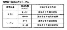
前記事前判定の結果に基づいて、特別遊技が行われることを期待させる第1の音(ズバーン(激熱音):図36(1)参照)または前記第1の音とは異なる第2の音(チロン:図35(1)参照)を前記音響出力手段から出力可能であり、
前記第1の音を出力する際に、前記保留図柄を前記通常表示態様で表示可能であり(図36(1)参照)、
前記第2の音を出力する際に、前記保留図柄を前記特別表示態様で表示可能であり(図35(1)参照)、
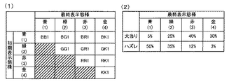
前記特別表示態様には、第1特別表示態様(例えば、青、緑)と当該第1特別表示態様よりも前記特別遊技が行われる可能性が高いことを示唆する第2特別表示態様(例えば、赤、金)が含まれ、
前記保留図柄が前記通常表示態様で表示されて前記第1の音が出力されたとき、当該保留図柄に対応される遊技情報に基づく前記特別遊技判定が行われた後に、当該保留図柄を、最終的な表示態様として、前記第1特別表示態様よりも前記第2特別表示態様で表示し易く図26、図36(7)参照)、
前記第2の音よりも前記第1の音の方が、特別遊技が行われることを強く期待させる。
A gaming machine (1) according to one aspect of the present invention includes:
Special game determination means (100) for performing a special game determination as to whether or not to execute a special game (big hit game) based on the game information acquired by establishing the start condition;
Storage means (100) capable of storing the game information;
Prior determination means (100) for performing a prior determination as to whether or not to perform a special game before the special game determination based on the game information stored in the storage means is performed;
Production control means (400, 500) for performing production using display means (6) and sound output means (35) for outputting sound,
The production control means includes
The holding symbol (holding image) corresponding to the game information stored in the storage unit can be displayed on the display unit in a normal display mode (default display mode) that does not suggest the possibility of a special game being performed,
Based on the result of the prior determination, the display in a special display mode (color display mode) suggesting that there is a higher possibility that a special game will be performed than when the reserved symbols are displayed in the normal display mode. Can be displayed on the means (see, for example, RI2 in FIG. 35 (1)),
Based on the result of the prior determination, a first sound that expects a special game to be played (Zuburn (super hot sound): see FIG. 36 (1)) or a second sound different from the first sound. Sound (Chillon: see FIG. 35 (1)) can be output from the sound output means,
When outputting the first sound, the reserved symbol can be displayed in the normal display mode (see FIG. 36 (1)),
When outputting the second sound, the reserved symbol can be displayed in the special display mode (see FIG. 35 (1)),
The special display mode includes a first special display mode (e.g., blue, green) and a second special display mode (e.g., suggesting that the special game is more likely to be performed than the first special display mode). Red, gold)
When the reserved symbol is displayed in the normal display mode and the first sound is output, after the special game determination based on the game information corresponding to the reserved symbol is performed, the reserved symbol is As a typical display mode, it is easier to display in the second special display mode than in the first special display mode ( see FIGS . 26 and 36 ( 7)),
The first sound is more strongly expected to play a special game than the second sound.

本発明によれば、遊技者の興味を惹きつけることができる遊技機を提供することができる。   ADVANTAGE OF THE INVENTION According to this invention, the gaming machine which can attract a player's interest can be provided.

本発明の第1の実施形態に係るパチンコ遊技機1の一例を示す概略正面図Schematic front view showing an example of a pachinko gaming machine 1 according to the first embodiment of the present invention 図1のパチンコ遊技機1に設けられた表示器4の一例を示す拡大図The enlarged view which shows an example of the indicator 4 provided in the pachinko machine 1 of FIG. 図1のパチンコ遊技機1の部分平面図Partial plan view of the pachinko gaming machine 1 of FIG. パチンコ遊技機1に設けられた制御装置の構成の一例を示すブロック図The block diagram which shows an example of a structure of the control apparatus provided in the pachinko gaming machine 1 第1の実施形態に特有の遊技球通過判定処理の一例について説明するための図The figure for demonstrating an example of the game ball passage determination process peculiar to 1st Embodiment. メイン制御部100によって実行されるメイン処理を示すフローチャートの一例An example of a flowchart showing main processing executed by the main control unit 100 図6のステップS911における電源遮断監視処理の詳細フローチャートの一例An example of a detailed flowchart of the power-off monitoring process in step S911 in FIG. 図6のステップS909における復旧処理の詳細フローチャートの一例An example of a detailed flowchart of the recovery process in step S909 of FIG. メイン制御部100によって行われるタイマ割込み処理を示すフローチャートの一例An example of a flowchart showing timer interrupt processing performed by the main control unit 100 特図ゲームカウント処理および普図ゲームカウント処理を実行する際に使用されるデータ、および、メイン制御部100のRAM103の記憶エリア(作業エリア)について説明するための図The figure for demonstrating the data used when performing a special figure game count process and a usual figure game count process, and the storage area (working area) of RAM103 of the main control part 100 特別図柄変動表示の時間をエリア11Aに設定するために用いられる変動時間テーブルの概念図の一例An example of a conceptual diagram of a variation time table used for setting the special symbol variation display time in the area 11A 図9のステップS2における始動口スイッチ処理の詳細フローチャートの一例An example of a detailed flowchart of the start port switch process in step S2 of FIG. 図9のステップS4における特別図柄処理の詳細フローチャートの一例An example of a detailed flowchart of the special symbol process in step S4 of FIG. 変動パターン決定テーブルの一例を説明するための図The figure for demonstrating an example of a fluctuation pattern determination table 変動パターン決定テーブルの一例を説明するための図The figure for demonstrating an example of a fluctuation pattern determination table 変動パターン決定テーブルの一例を説明するための図The figure for demonstrating an example of a fluctuation pattern determination table 変動パターン決定テーブルの一例を説明するための図The figure for demonstrating an example of a fluctuation pattern determination table 図9のステップS6における大入賞口処理の詳細フローチャートの一例An example of a detailed flowchart of the big prize opening process in step S6 of FIG. 図9のステップS6における大入賞口処理の詳細フローチャートの一例An example of a detailed flowchart of the big prize opening process in step S6 of FIG. 演出制御部400によって行われるタイマ割込み処理を示すフローチャートの一例An example of a flowchart showing timer interrupt processing performed by the effect control unit 400 図20のステップS11におけるコマンド受信処理を示す詳細フローチャートの一例An example of a detailed flowchart showing command reception processing in step S11 of FIG. 図20のステップS11におけるコマンド受信処理を示す詳細フローチャートの一例An example of a detailed flowchart showing command reception processing in step S11 of FIG. 図21のステップS112における先読み予告設定処理を示す詳細フローチャートの一例An example of a detailed flowchart showing the prefetch notice setting process in step S112 in FIG. 第1の実施形態に係る先読み予告演出決定テーブルの一例An example of a prefetch notice effect determination table according to the first embodiment 第1の実施形態に係る激熱音予告演出決定テーブルの一例An example of the intense heat sound notice effect determination table according to the first embodiment 第1の実施形態に係る激熱音予告演出実行対象保留画像の最終表示態様決定テーブルの一例An example of the final display mode determination table for the intense heat sound announcement effect execution target reserved image according to the first embodiment 第1の実施形態に係る激熱音予告演出実行対象保留画像の変化パターンの一例An example of a change pattern of a reserved image to be subjected to the intense heat sound announcement effect according to the first embodiment 第1の実施形態に係る激熱音予告演出非実行の保留変化予告演出実行対象保留画像の初期表示態様及び最終表示態様決定する際に参照される保留変化テーブルの一例An example of a hold change table that is referred to when determining an initial display mode and a final display mode of a hold change notice effect execution target hold image that is not executed according to the first embodiment. 第1の実施形態に係る激熱音予告演出非実行の保留変化予告演出実行対象保留画像の変化パターンの一例An example of a change pattern of a hold change notice effect execution target hold image for non-execution of intense heat sound notice effect according to the first embodiment 図21のステップS115における報知演出設定処理を示す詳細フローチャートの一例An example of a detailed flowchart showing the notification effect setting process in step S115 of FIG. 図30のステップS1153における保留画像表示態様変化設定処理を示す詳細フローチャートの一例30 is an example of a detailed flowchart showing the hold image display mode change setting process in step S1153 of FIG. 第1の実施形態において画像音響制御部500によって行われるタイマ割込み処理の一部を示すフローチャートの一例An example of a flowchart showing a part of timer interruption processing performed by the image sound control unit 500 in the first embodiment 第1の実施形態において画像音響制御部500によって行われるタイマ割込み処理の一部を示すフローチャートの一例An example of a flowchart showing a part of timer interruption processing performed by the image sound control unit 500 in the first embodiment 保留画像および消化保留画像について説明するための図The figure for demonstrating a hold image and a digestion hold image 第1の実施形態に係る画像表示部6において表示される演出画像の一例について説明するための図The figure for demonstrating an example of the production image displayed in the image display part 6 which concerns on 1st Embodiment. 第1の実施形態に係る画像表示部6において表示される演出画像の一例について説明するための図The figure for demonstrating an example of the production image displayed in the image display part 6 which concerns on 1st Embodiment. 第2の実施形態に係る激熱音予告演出実行対象保留画像の変化パターンの一例An example of a change pattern of a reserved image to be subjected to the intense heat sound announcement effect according to the second embodiment 第2の実施形態において画像音響制御部500によって行われるタイマ割込み処理の一部を示すフローチャートの一例An example of a flowchart showing a part of timer interruption processing performed by the image sound control unit 500 in the second embodiment 第2の実施形態において画像音響制御部500によって行われるタイマ割込み処理の一部を示すフローチャートの一例An example of a flowchart showing a part of timer interruption processing performed by the image sound control unit 500 in the second embodiment 第2の実施形態に係る画像表示部6において表示される演出画像の一例について説明するための図The figure for demonstrating an example of the production image displayed in the image display part 6 which concerns on 2nd Embodiment.

[第1の実施形態]
以下、適宜図面を参照しつつ、本発明の第1の実施形態に係るパチンコ遊技機1について説明する。なお、以下では、パチンコ遊技機1を、単に、遊技機1という場合がある。
[First Embodiment]
Hereinafter, the pachinko gaming machine 1 according to the first embodiment of the present invention will be described with reference to the drawings as appropriate. Hereinafter, the pachinko gaming machine 1 may be simply referred to as a gaming machine 1.

[パチンコ遊技機1の概略構成]
以下、図1〜図3を参照して、本発明の第1の実施形態に係るパチンコ遊技機1の概略構成について説明する。なお、図1は、本発明の第1の実施形態に係る遊技機1の一例を示す概略正面図である。図2は、遊技機1に設けられた表示器4の一例を示す拡大図である。図3は、遊技機1の部分平面図である。
[Schematic configuration of pachinko gaming machine 1]
Hereinafter, a schematic configuration of the pachinko gaming machine 1 according to the first embodiment of the present invention will be described with reference to FIGS. FIG. 1 is a schematic front view showing an example of the gaming machine 1 according to the first embodiment of the present invention. FIG. 2 is an enlarged view showing an example of the display 4 provided in the gaming machine 1. FIG. 3 is a partial plan view of the gaming machine 1.

図1において、遊技機1は、例えば遊技者の操作により打ち出された遊技球が入賞すると賞球を払い出すように構成されたパチンコ遊技機である。この遊技機1は、遊技球が打ち出される遊技盤2と、遊技盤2を囲む枠部材5とを備えている。枠部材5は、軸支側に設けられた蝶番を中心に、遊技機1の主部に対して開閉可能に構成されている。そして、枠部材5の前面側となる所定位置(例えば、軸支側とは反対側となる端部)には錠部43が設けられており、錠部43を開錠することによって枠部材5を開くことが可能となる。   In FIG. 1, a gaming machine 1 is a pachinko gaming machine configured to pay out a winning ball when a gaming ball launched by a player's operation wins a prize, for example. This gaming machine 1 includes a game board 2 on which game balls are launched, and a frame member 5 surrounding the game board 2. The frame member 5 is configured to be openable and closable with respect to the main part of the gaming machine 1 around a hinge provided on the shaft support side. And the lock part 43 is provided in the predetermined position (for example, edge part on the opposite side to a shaft support side) which becomes the front side of the frame member 5, and the frame member 5 is unlocked by unlocking the lock part 43. Can be opened.

遊技盤2は、その前面に、遊技球により遊技を行うための遊技領域20が形成されている。遊技領域20には、下方(発射装置211;図4参照)から発射された遊技球が遊技盤2の主面に沿って上昇して遊技領域20の上部位置へ向かう通路を形成するレール部材(図示せず)と、上昇した遊技球を遊技領域20の右側に案内する案内部材(図示せず)とが備えられている。   A game area 20 for playing a game with a game ball is formed on the front surface of the game board 2. In the gaming area 20, a rail member (from which a game ball launched from below (the launching device 211; see FIG. 4) rises along the main surface of the game board 2 and forms a path toward the upper position of the gaming area 20 ( (Not shown) and a guide member (not shown) for guiding the raised game ball to the right side of the game area 20.

また、遊技盤2には、遊技者により視認され易い位置に、各種演出のための画像を表示する画像表示部6が配設されている。画像表示部6は、遊技者による遊技の進行に応じて、例えば、装飾図柄を表示することによって特別図柄抽選(大当り抽選)の結果を遊技者に報知したり、キャラクタの登場やアイテムの出現等による予告演出を表示したり、特別図柄抽選が保留されている回数を示す保留画像を表示したりする。なお、画像表示部6は、液晶表示装置やEL(Electro Luminescence:電界発光)表示装置等によって構成されるが、他の任意の表示装置を利用してもよい。さらに、遊技盤2の前面には、各種の演出に用いられる可動役物7および盤ランプ8が設けられている。可動役物7は、遊技盤2に対して可動に構成され、遊技の進行に応じて又は遊技者の操作に応じて、所定の動作を行うことによって演出を行う。また、盤ランプ8は、遊技の進行に応じて発光することによって光による各種の演出を行う。   In addition, the game board 2 is provided with an image display unit 6 that displays images for various effects at positions that are easily visible to the player. The image display unit 6 notifies the player of the result of the special symbol lottery (big hit lottery), for example, by displaying a decorative symbol according to the progress of the game by the player, the appearance of a character, the appearance of an item, etc. Or a reserved image showing the number of times the special symbol lottery is held. The image display unit 6 is configured by a liquid crystal display device, an EL (Electro Luminescence) display device, or the like, but any other display device may be used. Furthermore, a movable accessory 7 and a board lamp 8 used for various effects are provided on the front surface of the game board 2. The movable accessory 7 is configured to be movable with respect to the game board 2, and produces an effect by performing a predetermined operation in accordance with the progress of the game or in accordance with the operation of the player. The board lamp 8 emits light according to the progress of the game, thereby performing various effects by light.

遊技領域20には、遊技球の落下方向を変化させる遊技くぎ及び風車(共に図示せず)等が配設されている。また、遊技領域20には、入賞や抽選に関する種々の役物が所定の位置に配設されている。なお、図1においては、入賞や抽選に関する種々の役物の一例として、第1始動口21、第2始動口22、ゲート25、大入賞口23、および普通入賞口24が遊技盤2に配設されている。さらに、遊技領域20には、遊技領域20に打ち出された遊技球のうち何れの入賞口にも入賞しなかった遊技球を、遊技領域20の外に排出する排出口26が配設されている。   In the game area 20, a game nail and a windmill (both not shown) that change the falling direction of the game ball are arranged. Further, in the game area 20, various bonuses related to winning and lottery are arranged at predetermined positions. In FIG. 1, the first start port 21, the second start port 22, the gate 25, the big winning port 23, and the normal winning port 24 are arranged on the game board 2 as an example of various prizes related to winning and lottery. It is installed. In addition, the game area 20 is provided with a discharge port 26 through which game balls that have not been won in any of the game areas of the game balls launched into the game area 20 are discharged out of the game area 20. .

第1始動口21および第2始動口22は、それぞれ遊技球が入ると入賞して特別図柄抽選(大当り抽選)が始動する。第1始動口21は、予め定められた特別電動役物(大入賞口23)および/または予め定められた特別図柄表示器(後述する第1特別図柄表示器4a)を作動させることとなる、遊技球の入賞に係る入賞口である。また、第2始動口22は、上記特別電動役物および/または予め定められた特別図柄表示器(後述する第2特別図柄表示器4b)を作動させることとなる、遊技球の入賞に係る入賞口である。ゲート25を遊技球が通過すると普通図柄抽選(下記の電動チューリップ27の開閉抽選)が始動する。なお、普通入賞口24に遊技球が入賞しても抽選は始動しない。   The first start port 21 and the second start port 22 are awarded when a game ball enters, respectively, and a special symbol lottery (big hit lottery) is started. The first start port 21 operates a predetermined special electric accessory (large winning port 23) and / or a predetermined special symbol display (first special symbol display 4a described later). It is a winning opening related to winning a game ball. Further, the second start opening 22 operates the special electric accessory and / or a predetermined special symbol display device (second special symbol display device 4b described later), and wins related to winning a game ball. The mouth. When the game ball passes through the gate 25, the normal symbol lottery (the open / close lottery of the electric tulip 27 described below) starts. The lottery is not started even if a game ball wins the normal winning opening 24.

第2始動口22は、第1始動口21の下部に設けられ、普通電動役物の一例として、遊技球の入口近傍に電動チューリップ27を備えている。電動チューリップ27は、チューリップの花を模した一対の羽根部を有しており、後述する電動チューリップ開閉部112(例えば、電動ソレノイド)の駆動によって当該一対の羽根部が左右に開閉する。電動チューリップ27は、一対の羽根部が閉じていると、第2始動口22の入口へ案内される開口幅が極めて狭いため、遊技球が第2始動口22へ入らない閉状態となる。一方、電動チューリップ27は、一対の羽根部が左右に開くと、第2始動口22の入口へ案内される開口幅が拡大するため、遊技球が第2始動口22へ入り易い開状態となる。そして、電動チューリップ27は、ゲート25を遊技球が通過して普通図柄抽選に当選すると、一対の羽根部が規定時間(例えば、0.10秒間)開き、規定回数(例えば、1回)だけ開閉する。   The 2nd starting port 22 is provided in the lower part of the 1st starting port 21, and is equipped with the electric tulip 27 in the vicinity of the entrance of a game ball as an example of a normal electric accessory. The electric tulip 27 has a pair of wings imitating tulip flowers, and the pair of wings opens and closes left and right by driving an electric tulip opening / closing unit 112 (for example, an electric solenoid) described later. When the pair of blade portions are closed, the electric tulip 27 is in a closed state in which the game ball does not enter the second start port 22 because the opening width guided to the entrance of the second start port 22 is extremely narrow. On the other hand, the electric tulip 27 is in an open state in which the game ball can easily enter the second starting port 22 because the opening width guided to the inlet of the second starting port 22 increases when the pair of wings open to the left and right. . When the electric tulip 27 passes through the gate 25 and the normal symbol lottery is won, the pair of blades opens for a specified time (for example, 0.10 seconds) and opens and closes for a specified number of times (for example, once). To do.

大入賞口23は、第2始動口22の下側中央に位置し、特別図柄抽選の結果に応じて開放する。大入賞口23は、通常は閉状態であり遊技球が入ることがない状態となっているが、特別図柄抽選の結果に応じて遊技盤2の主面から突出傾斜して開状態となって遊技球が入り易い状態となる。例えば、大入賞口23は、所定条件(例えば、29.5秒経過または遊技球10個の入賞)を満たすまで開状態となるラウンドを、所定回数(例えば、16回)だけ繰り返す。   The big winning opening 23 is located at the lower center of the second starting opening 22 and is opened according to the result of the special symbol lottery. The big prize opening 23 is normally in a closed state so that no game balls can enter, but depending on the result of the special symbol lottery, it protrudes from the main surface of the game board 2 and is in an open state. The game ball is easy to enter. For example, the special winning opening 23 repeats a round that is in an open state until a predetermined condition (for example, 29.5 seconds elapses or a winning of 10 game balls) is satisfied a predetermined number of times (for example, 16 times).

また、遊技盤2の右下には、上述した特別図柄抽選や普通図柄抽選の結果や保留数に関する表示を行う表示器4が配設されている。表示器4の詳細については後述する。   Further, on the lower right side of the game board 2, a display 4 for displaying the results of the special symbol lottery and the normal symbol lottery described above and the number of reserved items is arranged. Details of the display 4 will be described later.

ここで、賞球の払い出しについて説明する。第1始動口21、第2始動口22、大入賞口23、および普通入賞口24に遊技球が入る(入賞する)と、遊技球が入賞した場所に応じて、1つの遊技球当たり規定個数の賞球が払い出される。例えば、第1始動口21および第2始動口22に遊技球が1個入賞すると3個の賞球、大入賞口23に遊技球が1個入賞すると13個の賞球、普通入賞口24に遊技球が1個入賞すると10個の賞球がそれぞれ払い出される。なお、ゲート25を遊技球が通過したことを検出しても、それに連動した賞球の払い出しは無い。   Here, the payout of prize balls will be described. When a game ball enters (wins) the first start port 21, the second start port 22, the big winning port 23, and the normal winning port 24, a predetermined number per game ball is determined according to the place where the game ball has won. The prize ball is paid out. For example, when one game ball is won at the first start port 21 and the second start port 22, three prize balls are awarded, and when one game ball is won at the big prize port 23, thirteen prize balls are given to the normal prize slot 24. When one game ball is won, ten prize balls are paid out. Even if it is detected that the game ball has passed through the gate 25, there is no payout of the prize ball in conjunction with it.

遊技機1の前面となる枠部材5には、ハンドル31、レバー32、停止ボタン33、取り出しボタン34、スピーカ35、枠ランプ36、演出ボタン37、演出キー38、および皿39等が設けられている。   The frame member 5 on the front surface of the gaming machine 1 is provided with a handle 31, a lever 32, a stop button 33, a take-out button 34, a speaker 35, a frame lamp 36, an effect button 37, an effect key 38, a dish 39, and the like. Yes.

遊技者がハンドル31に触れてレバー32を時計回りに回転させる操作を行うと、その操作角度に応じた打球力にて所定の時間間隔(例えば、1分間に100個)で、発射装置211(図4参照)が遊技球を電動発射する。皿39(図3参照)は、遊技機1の前方に突出して設けられ、発射装置211に供給される遊技球を一時的に溜めておく。また、皿39には、上述した賞球が払い出される。そして、皿39に溜められた遊技球は、遊技者のレバー32による操作と連動したタイミングで、供給装置(図示せず)によって1つずつ発射装置211に供給される。   When the player touches the handle 31 and performs an operation to rotate the lever 32 clockwise, the launching device 211 (100 per minute) with a hitting force according to the operation angle (for example, 100 per minute). 4) electrically fires the game ball. The tray 39 (see FIG. 3) is provided so as to protrude in front of the gaming machine 1 and temporarily stores game balls supplied to the launching device 211. In addition, the above-described prize balls are paid out to the plate 39. The game balls stored in the tray 39 are supplied to the launching device 211 one by one by a supply device (not shown) at a timing linked with the operation by the player's lever 32.

停止ボタン33は、ハンドル31の下部側面に設けられ、ハンドル31に遊技者が触れてレバー32を時計回りに回転させている状態であっても、遊技者に押下されることによって遊技球の発射を一時的に停止させる。取り出しボタン34は、皿39が設けられた位置近傍の前面に設けられ、遊技者に押下されることによって皿39に溜まっている遊技球を箱(図示せず)に落下させる。   The stop button 33 is provided on the lower side surface of the handle 31, and even when the player touches the handle 31 and rotates the lever 32 in the clockwise direction, the game ball is released by being pressed by the player. Is temporarily stopped. The take-out button 34 is provided on the front surface in the vicinity of the position where the tray 39 is provided, and when the player presses it, the game balls accumulated in the tray 39 are dropped into a box (not shown).

スピーカ35および枠ランプ36は、それぞれ遊技機1の遊技状態や状況を告知したり各種の演出を行ったりする。スピーカ35は、楽曲や音声、効果音による各種の演出を行う。また、枠ランプ36は、点灯/点滅によるパターンや発光色の違い等によって光による各種の演出を行う。   The speaker 35 and the frame lamp 36 respectively notify the gaming state and situation of the gaming machine 1 and perform various effects. The speaker 35 performs various effects using music, voice, and sound effects. In addition, the frame lamp 36 performs various effects by light depending on a pattern by lighting / flashing or a difference in emission color.

次に、図2を参照して、遊技機1に設けられる表示器4について説明する。図2において、表示器4は、第1特別図柄表示器4a、第2特別図柄表示器4b、第1特別図柄保留表示器4c、第2特別図柄保留表示器4d、普通図柄表示器4e、普通図柄保留表示器4f、および遊技状態表示器4gを備えている。   Next, the display 4 provided in the gaming machine 1 will be described with reference to FIG. In FIG. 2, the display 4 includes a first special symbol display 4a, a second special symbol display 4b, a first special symbol hold indicator 4c, a second special symbol hold indicator 4d, a normal symbol indicator 4e, and a normal symbol indicator 4e. A symbol hold display 4f and a game status display 4g are provided.

第1特別図柄表示器4aは、第1始動口21に遊技球が入賞することに対応して表示図柄が変動して表示される。例えば、第1特別図柄表示器4aは、7セグ表示装置で構成され、第1始動口21に遊技球が入賞した場合、特別図柄を変動表示した後に停止表示してその抽選結果を表示する。また、第2特別図柄表示器4bは、第2始動口22に遊技球が入賞することに対応して表示図柄が変動して表示される。例えば、第2特別図柄表示器4bも同様に、7セグ表示装置で構成され、第2始動口22に遊技球が入賞した場合、特別図柄を変動表示した後に停止表示してその抽選結果を表示する。普通図柄表示器4eは、ゲート25を遊技球が通過することに対応して表示図柄が変動して表示される。例えば、普通図柄表示器4eは、LED表示装置で構成され、遊技球がゲート25を通過した場合、普通図柄を変動表示した後に停止表示してその抽選結果を表示する。   The first special symbol display 4a is displayed with the display symbol varying corresponding to the winning of the game ball at the first starting port 21. For example, the first special symbol display 4a is composed of a 7-segment display device, and when a game ball is won at the first starting port 21, the special symbol is displayed in a variable manner, and then the lottery result is displayed. Further, the second special symbol display 4b is displayed with the display symbols varying corresponding to the winning of the game ball at the second starting port 22. For example, the second special symbol display 4b is similarly composed of a 7-segment display device, and when a game ball wins at the second starting port 22, the special symbol is displayed in a variable manner and then stopped and the lottery result is displayed. To do. In the normal symbol display 4e, the display symbol is changed and displayed in response to the game ball passing through the gate 25. For example, the normal symbol display 4e is constituted by an LED display device, and when a game ball passes through the gate 25, the normal symbol is variably displayed and then stopped and displayed.

第1特別図柄保留表示器4cは、第1始動口21に遊技球が入賞した場合の特別図柄抽選を保留している回数を表示する。第2特別図柄保留表示器4dは、第2始動口22に遊技球が入賞した場合の特別図柄抽選を保留している回数を表示する。普通図柄保留表示器4fは、普通図柄抽選を保留している回数を表示する。例えば、第1特別図柄保留表示器4c、第2特別図柄保留表示器4d、および普通図柄保留表示器4fは、それぞれ列設されたLED表示装置で構成され、その点灯態様によって保留回数が表示される。   The first special symbol hold indicator 4c displays the number of times that the special symbol lottery is held when a game ball wins at the first start port 21. The second special symbol hold indicator 4d displays the number of times that the special symbol lottery is held when the game ball wins at the second start port 22. The normal symbol hold display 4f displays the number of times the normal symbol lottery is held. For example, the first special symbol hold indicator 4c, the second special symbol hold indicator 4d, and the normal symbol hold indicator 4f are each composed of LED display devices arranged in a row, and the number of times of hold is displayed according to the lighting mode. The

遊技状態表示器4gは、遊技機1の電源投入時点における遊技状態(時短状態等)を表示する。   The game state display 4g displays a game state (such as a short time state) when the gaming machine 1 is powered on.

次に、図3を参照して、遊技機1に設けられる入力装置について説明する。図3において、遊技機1には、入力装置の一例として、演出ボタン37および演出キー38が設けられている。   Next, an input device provided in the gaming machine 1 will be described with reference to FIG. In FIG. 3, the gaming machine 1 is provided with an effect button 37 and an effect key 38 as an example of an input device.

演出ボタン37および演出キー38は、それぞれ遊技者が演出に対する入力を行うために設けられている。演出ボタン37は、遊技機1の前方に突出した皿39の上面脇部に設けられる。演出キー38は、中央キーと略十字に配列された4つの方向キーとを有し、演出ボタン37に隣接して皿39の上面脇部に設けられる。演出ボタン37および演出キー38は、それぞれ遊技者に押下されることによって所定の演出が行われる。例えば、遊技者は、所定のタイミングで演出ボタン37を押下することによって所定の演出を楽しむことができる。また、遊技者は、演出キー38の4つの方向キーを操作することにより、画像表示部6に表示されている複数の画像のいずれかを選ぶこと等が可能である。また、遊技者は、演出キー38の中央キーを操作することにより、選んだ画像を情報として入力することが可能である。   The effect button 37 and the effect key 38 are provided for the player to input the effect. The effect button 37 is provided on the side of the upper surface of the tray 39 protruding forward of the gaming machine 1. The production key 38 has a center key and four direction keys arranged in a substantially cross shape, and is provided on the upper side of the plate 39 adjacent to the production button 37. The effect button 37 and the effect key 38 are each pressed by the player to perform a predetermined effect. For example, the player can enjoy a predetermined effect by pressing the effect button 37 at a predetermined timing. Further, the player can select one of a plurality of images displayed on the image display unit 6 by operating the four direction keys of the effect key 38. Further, the player can input the selected image as information by operating the center key of the effect key 38.

また、遊技機1の背面側には、払出用の遊技球を溜めておく球タンクや遊技球を皿39に払い出す払出装置(払出駆動部311)が設けられ、各種の基板等が取り付けられている。例えば、遊技盤2の後面には、メイン基板およびサブ基板等が配設されている。具体的には、メイン基板には、内部抽選および当選の判定等を行うメイン制御部100(図4参照)が構成されたメイン制御基板が配設されている。サブ基板には、遊技球を遊技領域20の上部へ発射する発射装置211を制御する発射制御部200(図4参照)が構成された発射制御基板、賞球の払出を制御する払出制御部300が構成された払出制御基板、演出を統括的に制御する演出制御部400が構成された演出制御基板、画像および音による演出を制御する画像音響制御部500が構成された画像制御基板、および各種のランプ(枠ランプ36、盤ランプ8)や可動役物7による演出を制御するランプ制御部600が構成されたランプ制御基板等が配設されている。また、遊技盤2の後面には、遊技機1の電源オン/オフを切り替えるとともに、遊技機1に供給された24V(ボルト)の交流電力を各種電圧の直流電力に変換して、それぞれの電圧の直流電力を上述した各種の基板等に出力するスイッチング電源が配設されている。   In addition, on the back side of the gaming machine 1, a ball tank for storing game balls for payout and a payout device (payout drive unit 311) for paying out the game balls to the tray 39 are provided, and various substrates are attached. ing. For example, a main board, a sub board, and the like are disposed on the rear surface of the game board 2. Specifically, a main control board on which a main control unit 100 (see FIG. 4) that performs internal lottery and determination of winning is configured is disposed on the main board. The sub-board includes a firing control board 200 (see FIG. 4) configured to control a launching device 211 that launches a game ball to the upper part of the game area 20, and a payout control unit 300 that controls the payout of a prize ball. A payout control board configured with an effect control board configured with an effect control section 400 for overall control of effects, an image control board configured with an image acoustic control section 500 for controlling effects with images and sounds, and various types The lamp control board etc. in which the lamp control part 600 which controls the effect by the lamp (frame lamp 36, panel lamp 8) and the movable accessory 7 are arranged. In addition, on the rear surface of the gaming board 2, the power source of the gaming machine 1 is switched on / off, and 24V (volt) AC power supplied to the gaming machine 1 is converted into DC power of various voltages. A switching power supply is provided for outputting the direct current power to the various substrates described above.

[パチンコ遊技機1の制御装置の構成]
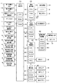
次に、図4を参照して、遊技機1における動作制御や信号処理を行う制御装置について説明する。なお、図4は、遊技機1に設けられた制御装置の構成の一例を示すブロック図である。
[Configuration of control device of pachinko gaming machine 1]
Next, with reference to FIG. 4, a control device that performs operation control and signal processing in the gaming machine 1 will be described. FIG. 4 is a block diagram showing an example of the configuration of the control device provided in the gaming machine 1.

図4において、遊技機1の制御装置は、メイン制御部100、発射制御部200、払出制御部300、演出制御部400、画像音響制御部500、およびランプ制御部600等を備えている。   4, the control device of the gaming machine 1 includes a main control unit 100, a launch control unit 200, a payout control unit 300, an effect control unit 400, an image sound control unit 500, a lamp control unit 600, and the like.

メイン制御部100は、CPU(Central Processing Unit;中央処理装置)101、ROM(Read Only Memory)102、およびRAM(Random Access Memory)103を備えている。CPU101は、内部抽選および当選の判定等の払い出し賞球数に関連する各種制御を行う際の演算処理を行う。ROM102には、CPU101により実行されるプログラムや各種データ等が記憶されている。RAM103は、CPU101の作業用メモリ等として用いられる。以下、メイン制御部100の主な機能について説明する。   The main control unit 100 includes a CPU (Central Processing Unit) 101, a ROM (Read Only Memory) 102, and a RAM (Random Access Memory) 103. The CPU 101 performs arithmetic processing when performing various controls related to the number of payout prize balls, such as internal lottery and determination of winning. The ROM 102 stores programs executed by the CPU 101 and various data. The RAM 103 is used as a working memory for the CPU 101. Hereinafter, main functions of the main control unit 100 will be described.

メイン制御部100は、第1始動口21または第2始動口22に遊技球が入賞すると特別図柄抽選(大当り抽選)を行い、特別図柄抽選で当選したか否かを示す判定結果データを演出制御部400に送る。   The main control unit 100 performs a special symbol lottery (big hit lottery) when a game ball wins at the first starting port 21 or the second starting port 22, and effects control is performed on determination result data indicating whether or not the special symbol lottery is won. Send to part 400.

メイン制御部100は、電動チューリップ27の羽根部が開状態となる開時間や羽根部が開閉する回数、さらには羽根部が開閉する開閉時間間隔を制御する。また、メイン制御部100は、遊技球が第1始動口21へ入賞したときの特別図柄抽選の実行保留回数、遊技球が第2始動口22へ入賞したときの特別図柄抽選の実行保留回数、および遊技球がゲート25を通過したときの普通図柄抽選の実行保留回数をそれぞれ管理し、これらの保留回数に関連するデータを演出制御部400に送る。   The main control unit 100 controls the opening time when the blade portion of the electric tulip 27 is opened, the number of times the blade portion is opened and closed, and the opening / closing time interval at which the blade portion is opened and closed. Further, the main control unit 100 executes the special symbol lottery execution suspension number when the game ball wins the first start port 21, the special symbol lottery execution suspension number when the game ball wins the second start port 22, In addition, the number of execution suspensions of the normal symbol lottery when the game ball passes through the gate 25 is managed, and data related to the number of suspensions is sent to the effect control unit 400.

メイン制御部100は、特別図柄抽選の結果に応じて、大入賞口23の開閉動作を制御する。例えば、メイン制御部100は、所定条件(例えば、29.5秒経過または遊技球10個の入賞)を満たすまで、大入賞口23が突出傾斜して開状態となるラウンドを所定回数(例えば、16回)だけ繰り返すように制御する。また、メイン制御部100は、大入賞口23が開閉する開閉時間間隔を制御する。   The main control unit 100 controls the opening / closing operation of the special winning opening 23 according to the result of the special symbol lottery. For example, the main controller 100 repeats a predetermined number of rounds (for example, 29.5 seconds have passed or 10 game balls have been won) in which the big winning opening 23 projects and inclines and opens. (16 times). Further, the main control unit 100 controls the opening / closing time interval at which the special winning opening 23 opens and closes.

メイン制御部100は、遊技の進行に応じて遊技状態を変化させ、又、遊技の進行に応じて、特別図柄抽選の当選確率、特別図柄抽選の実行間隔(特別図柄が表示器4に変動表示されて停止表示される時間と言ってもよい)、電動チューリップ27の開閉動作等を変化させる。   The main control unit 100 changes the game state in accordance with the progress of the game, and according to the progress of the game, the winning probability of the special symbol lottery, the execution interval of the special symbol lottery (the special symbol is variably displayed on the display 4) In other words, it may be said that it is a time to stop and display), and the opening / closing operation of the electric tulip 27 is changed.

メイン制御部100は、第1始動口21、第2始動口22、大入賞口23、および普通入賞口24に遊技球が入賞すると、遊技球が入賞した場所に応じて1つの遊技球当たり所定数の賞球を払い出すように払出制御部300に対して指示する。なお、メイン制御部100は、ゲート25を遊技球が通過したことを検出しても、それに連動した賞球の払い出しを払出制御部300に指示しない。払出制御部300がメイン制御部100の指示に応じて賞球の払い出しを行った場合、払出制御部300から払い出した賞球の個数に関する情報がメイン制御部100へ送られる。そして、メイン制御部100は、払出制御部300から取得した情報に基づいて、払い出した賞球の個数を管理する。   When a game ball wins the first start port 21, the second start port 22, the big winning port 23, and the normal winning port 24, the main control unit 100 determines a predetermined amount per game ball according to the place where the game ball has won. The payout control unit 300 is instructed to pay out a number of prize balls. Even if the main control unit 100 detects that the game ball has passed through the gate 25, the main control unit 100 does not instruct the payout control unit 300 to pay out the prize ball in conjunction therewith. When the payout control unit 300 pays out a prize ball according to an instruction from the main control unit 100, information on the number of prize balls paid out from the payout control unit 300 is sent to the main control unit 100. Then, the main control unit 100 manages the number of paid-out prize balls based on the information acquired from the payout control unit 300.

上述した機能を実現するために、メイン制御部100には、第1始動口スイッチ111a、第2始動口スイッチ111b、電動チューリップ開閉部112、ゲートスイッチ113、大入賞口スイッチ114、大入賞口開閉部115、普通入賞口スイッチ116、表示器4(第1特別図柄表示器4a、第2特別図柄表示器4b、第1特別図柄保留表示器4c、第2特別図柄保留表示器4d、普通図柄表示器4e、普通図柄保留表示器4f、および遊技状態表示器4g)が接続されている。   In order to realize the above-described functions, the main control unit 100 includes a first start port switch 111a, a second start port switch 111b, an electric tulip opening / closing unit 112, a gate switch 113, a big prize opening switch 114, a big prize opening opening / closing. 115, normal winning opening switch 116, display 4 (first special symbol display 4a, second special symbol display 4b, first special symbol hold indicator 4c, second special symbol hold indicator 4d, normal symbol display 4e, a normal symbol hold display 4f, and a game status display 4g) are connected.

第1始動口スイッチ111aは、第1始動口21へ遊技球が入賞したことに応じた信号をメイン制御部100へ送る。第2始動口スイッチ111bは、第2始動口22へ遊技球が入賞したことに応じた信号をメイン制御部100へ送る。電動チューリップ開閉部112は、メイン制御部100から送られる制御信号に応じて、電動チューリップ27の一対の羽根部を開閉する。ゲートスイッチ113は、ゲート25を遊技球が通過したことに応じた信号をメイン制御部100へ送る。大入賞口スイッチ114は、大入賞口23へ遊技球が入賞したことに応じた信号をメイン制御部100へ送る。大入賞口開閉部115は、メイン制御部100から送られる制御信号に応じて、大入賞口23を開閉する。普通入賞口スイッチ116は、普通入賞口24へ遊技球が入賞したことに応じた信号をメイン制御部100へ送る。   The first start port switch 111 a sends a signal to the main control unit 100 in response to the winning of the game ball to the first start port 21. The second start port switch 111 b sends a signal corresponding to the winning of the game ball to the second start port 22 to the main control unit 100. The electric tulip opening / closing unit 112 opens and closes the pair of blade portions of the electric tulip 27 in accordance with a control signal sent from the main control unit 100. The gate switch 113 sends a signal corresponding to the game ball passing through the gate 25 to the main control unit 100. The big winning opening switch 114 sends a signal corresponding to the winning of the game ball to the big winning opening 23 to the main control unit 100. The special prize opening / closing unit 115 opens and closes the special prize opening 23 in accordance with a control signal sent from the main control unit 100. The normal winning port switch 116 sends a signal to the main control unit 100 in response to the winning of the game ball to the normal winning port 24.

[第1の実施形態のスイッチ処理について]
以下では、第1の実施形態のスイッチ処理(遊技球通過判定処理)について、具体的に説明する。なお、この遊技球通過判定処理は、上記した第1始動口21、第2始動口22、ゲート25、大入賞口23等に遊技球が入球(又は通過)したことを判定する場合に限らず、例えば、払い出した賞球(賞球数)を払出制御部300が判定(カウント)する場合等にも実行される。
[Switch processing of the first embodiment]
Below, the switch process (game ball passage determination process) of the first embodiment will be specifically described. Note that this game ball passage determination process is limited to the case where it is determined that a game ball has entered (or passed) the first start port 21, the second start port 22, the gate 25, the big winning port 23, or the like. For example, it is also executed when the payout control unit 300 determines (counts) the paid-out prize balls (number of prize balls).

図5は、上記した第1始動口21等への遊技球入賞(通過)を検出するための第1始動口スイッチ111a等として設置される近接スイッチの出力信号の例、および、この出力信号を通過判定閾値(5V)を用いてONレベルとOFFレベルとに2値化した2値化信号の例について説明するための図である。なお、近接スイッチは、一例として、長方形のプレートに遊技球が通過する円形の貫通孔を有しており、この貫通孔を遊技球が通過する際の磁束の変化に対応した電圧の出力信号を出力する直流2線式電子スイッチである。図5の点線で示すように、近接スイッチの出力信号の電圧レベルは、遊技球が貫通孔の中心に近づくにつれて降下していき、遊技球が貫通孔の中心に達する辺りで最小(極小)となり、遊技球が貫通孔の中心を通り過ぎて離れるにつれて上昇していく。また、図5に示すように、近接スイッチの出力信号は、コンパレータ(図示なし)によって、電圧レベルが通過判定閾値(5V)よりも大きいときには2値化信号のOFFレベルに変換され、電圧レベルが通過判定閾値(5V)以下のときには2値化信号のONレベルに変換される。なお、図5の例では、判定に用いる通過判定閾値を1つの通過判定閾値(5V)として説明したが、例えば、OFFレベルからONレベルに切り替わる際には第1の通過判定閾値(5V)を用いる一方で、ONレベルからOFFレベルに切り替わる際には第2の通過判定閾値(6V)を用いる構成としてもよい。これにより、ノイズの影響等で通過判定閾値を跨いで近接スイッチの出力信号が上下することによって2値化信号が不適切にON/OFF間で行き来することを防止できる。   FIG. 5 shows an example of the output signal of the proximity switch installed as the first start port switch 111a for detecting the game ball winning (passing) to the first start port 21 and the like, and the output signal. It is a figure for demonstrating the example of the binarization signal binarized into the ON level and the OFF level using the passage determination threshold value (5V). As an example, the proximity switch has a circular through hole through which a game ball passes through a rectangular plate, and outputs an output signal of a voltage corresponding to a change in magnetic flux when the game ball passes through the through hole. This is a direct current 2-wire electronic switch for output. As shown by the dotted line in FIG. 5, the voltage level of the output signal of the proximity switch decreases as the game ball approaches the center of the through hole, and becomes the minimum (minimum) when the game ball reaches the center of the through hole. The game ball rises as it passes through the center of the through hole and leaves. Further, as shown in FIG. 5, the output signal of the proximity switch is converted to an OFF level of the binarized signal when the voltage level is larger than the passage determination threshold (5V) by a comparator (not shown), and the voltage level is When it is below the passage determination threshold value (5 V), it is converted into an ON level of the binarized signal. In the example of FIG. 5, the passage determination threshold used for the determination is described as one passage determination threshold (5V). However, for example, when switching from the OFF level to the ON level, the first passage determination threshold (5V) is used. On the other hand, the second passage determination threshold (6V) may be used when switching from the ON level to the OFF level. Thereby, it is possible to prevent the binarized signal from improperly switching between ON / OFF due to the output signal of the proximity switch going up and down across the passage determination threshold due to the influence of noise or the like.

そして、図9を用いて後述するメイン制御部100により4ミリ秒(4ms)間隔で実行されるタイマ割り込み処理における各処理の一部として、図5に示す2値化信号を4ミリ秒間隔でON/OFF判定することによって、遊技球の通過判定を行う。以下、具体的に説明する。   Then, as part of each process in the timer interrupt process executed at intervals of 4 milliseconds (4 ms) by the main control unit 100 described later with reference to FIG. 9, the binarized signal shown in FIG. By determining ON / OFF, the game ball is determined to pass. This will be specifically described below.

図5に示すように、2値化信号に対して、ONレベルであるのかOFFレベルであるのかが4ミリ秒間隔で判定(ON/OFF判定)される。図5では、自然数nを用いて、ON/OFF判定の順番を表している。また、図5では、n−2回目からn回目のON/OFF判定によってOFFレベルと判定され、その後、n+1回目のON/OFF判定によってONレベルと判定されている。ここで、第1の実施形態では、ONレベルと判定された場合には、このONレベルと判定したON/OFF判定の処理において、4ミリ秒間隔よりも短い所定の微小時間(例えば4マイクロ秒)が経過したタイミングで2回目のON/OFF判定を実行する。図5では、n+1回目のタイマ割り込み処理におけるON/OFF判定で2回ともONレベルと判定されている。その後、n+2回目からn+4回目のON/OFF判定によってOFFレベルと判定されている。なお、2値化信号のONレベルの期間(ON期間という)が図5の場合よりも長く(つまり、遊技球が図5の場合よりも遅い速度で通過して)例えばn+2回目のON/OFF判定もON期間に実行される場合には、n+2回目のON/OFF判定においても2回の判定を実行する。   As shown in FIG. 5, it is determined at intervals of 4 milliseconds (ON / OFF determination) whether the binary signal is at the ON level or the OFF level. In FIG. 5, the natural number n is used to represent the order of ON / OFF determination. In FIG. 5, the OFF level is determined by the (n−2) -th to n-th ON / OFF determinations, and then the ON level is determined by the (n + 1) th ON / OFF determination. Here, in the first embodiment, when the ON level is determined, in the ON / OFF determination processing determined to be the ON level, a predetermined minute time shorter than the 4 millisecond interval (for example, 4 microseconds). The second ON / OFF determination is executed at the timing when) elapses. In FIG. 5, the ON / OFF determination in the (n + 1) th timer interrupt process is determined to be the ON level both times. Thereafter, it is determined to be the OFF level by the ON / OFF determination from the (n + 2) th time to the (n + 4) th time. Note that the ON level period of the binarized signal (referred to as the ON period) is longer than in the case of FIG. 5 (that is, the game ball passes at a slower speed than in the case of FIG. 5). When the determination is also executed during the ON period, the determination is executed twice in the (n + 2) th ON / OFF determination.

第1の実施形態では、図5に示すように、n回目のON/OFF判定によってOFFレベルと判定されて、n+1回目のON/OFF判定によって2回ONレベルと判定されると、近接スイッチの貫通孔を遊技球が1つ通過したと判定する。なお、これらのON/OFF判定は、例えば第1始動口スイッチ111aとして設置された近接スイッチに対しては、メイン制御部100(より正確にはCPU101)が実行し、例えば払出制御部300に接続された遊技球の払い出し数を検出するための近接スイッチに対しては、払出制御部300(より正確にはCPU301)が実行する(図4参照)。   In the first embodiment, as shown in FIG. 5, when the ON level is determined by the nth ON / OFF determination and the ON level is determined twice by the (n + 1) th ON / OFF determination, the proximity switch It is determined that one game ball has passed through the through hole. The ON / OFF determination is performed by the main control unit 100 (more precisely, the CPU 101) for the proximity switch installed as the first start port switch 111a, for example, and connected to the payout control unit 300, for example. The payout control unit 300 (more precisely, the CPU 301) executes the proximity switch for detecting the payout number of the game balls that have been played (see FIG. 4).

ここで、図5に示すn+1回目のON/OFF判定における上記した所定の微小時間(例えば4マイクロ秒)は、遊技球通過判定の演算処理を実行するためのソフトウエアのプログラミング内容によって予め設定される。つまり、上記した所定の微小時間は、このプログラミング内容によって任意な時間に設定できる可変時間である。遊技機1には微細周期のノイズ(例えば3〜15マイクロ秒周期のノイズ)が発生する場合があり、このノイズの周期は、遊技機の機種に或る程度依存している。例えば、或る機種の遊技機には5マイクロ秒周期のノイズが発生し易く、或る機種の遊技機には9マイクロ秒周期のノイズが発生し易い。そこで、第1の実施形態では、上記した所定の微小時間をプログラミング内容によって任意な時間に設定できる構成とすることによって、微細周期のノイズによる誤判定を有効に回避することができる。なお、上記した所定の微小時間を設けるための演算処理は、遊技進行には関係しない処理であって時間を稼ぐためだけの処理である。例えば、1マイクロ秒の時間を要する処理を4回繰り返すことによって、上記した所定の微小時間として4マイクロ秒をソフト的に設けることができる。   Here, the predetermined minute time (for example, 4 microseconds) in the (n + 1) th ON / OFF determination shown in FIG. 5 is set in advance according to the software programming content for executing the calculation process of the game ball passage determination. The That is, the predetermined minute time described above is a variable time that can be set to an arbitrary time depending on the programming content. The gaming machine 1 may generate fine period noise (for example, noise of 3 to 15 microsecond period), and this noise period depends to some extent on the type of gaming machine. For example, a certain type of gaming machine is likely to generate noise with a period of 5 microseconds, and a certain type of gaming machine is likely to generate noise with a period of 9 microseconds. Therefore, in the first embodiment, by adopting a configuration in which the predetermined minute time described above can be set to an arbitrary time depending on the programming content, it is possible to effectively avoid erroneous determination due to noise of a fine cycle. Note that the arithmetic processing for providing the predetermined minute time described above is processing that is not related to the progress of the game and is only for earning time. For example, by repeating a process requiring a time of 1 microsecond four times, 4 microseconds can be provided as the above-mentioned predetermined minute time in software.

ところで、近年の遊技機では、演算処理内容の増大により演算処理の負荷が増大したために、以前の遊技機では2ミリ秒であったタイマ割り込み処理の実行間隔は4ミリ秒に延長され、このため、図5を用いて説明したように、近接スイッチを用いたON/OFF判定も2ミリ秒間隔から延長されて4ミリ秒間隔で実行される。   By the way, in recent gaming machines, the processing load has increased due to an increase in the contents of arithmetic processing, so the execution interval of timer interrupt processing, which was 2 milliseconds in the previous gaming machine, has been extended to 4 milliseconds. As described with reference to FIG. 5, the ON / OFF determination using the proximity switch is also extended from the 2 millisecond interval and executed at an interval of 4 millisecond.

ここで、以前の遊技機は、n回目のON/OFF判定でOFFレベルと判定してn+1回目のON/OFF判定でONレベルと判定してn+2回目のON/OFF判定でONレベルと判定したことをもって1つの遊技球が通過したと判定していた(以下、「以前の判定方法」という)。つまり、3回のタイマ割り込み処理による3回のON/OFF判定によって遊技球通過を判定していた。なお、このようにn+1回目およびn+2回目でONレベルと判定するのは、ノイズにより偶然ONレベルと1回判定されたことによって遊技球が通過したと誤判定することを回避するためである。しかしながら、ON/OFF判定の間隔が4ミリ秒間隔に延長された近年の遊技機においては、上記した以前の判定方法では、速い速度で通過する遊技球の通過を判定することはできない。例えば、図5に示すような2値化信号のONレベルの期間(ON期間)が非常に短くなる(例えば7ミリ秒前後)ほど、速い速度で通過する遊技球の通過を判定することは困難となってしまう。そこで、第1の実施形態では、図5を用いて説明した判定方法により、1つの遊技球が通過したと判定する。このことから、第1の実施形態によれば、2回のタイマ割り込み処理によるON/OFF判定によって、ノイズによる誤判定を防止しつつ確実に遊技球通過を判定することができる。   Here, the previous gaming machine is determined to be the OFF level by the nth ON / OFF determination, is determined to be the ON level by the (n + 1) th ON / OFF determination, and is determined to be the ON level by the (n + 2) th ON / OFF determination. As a result, it was determined that one game ball passed (hereinafter referred to as “previous determination method”). That is, the game ball passage is determined by three ON / OFF determinations by three timer interruption processes. The reason for determining the ON level at the (n + 1) th time and the (n + 2) th time as described above is to avoid erroneous determination that the game ball has passed due to the accidental determination of the ON level once due to noise. However, in a recent gaming machine in which the ON / OFF determination interval is extended to an interval of 4 milliseconds, the previous determination method described above cannot determine the passage of a game ball passing at a high speed. For example, as the binarized signal ON level period (ON period) shown in FIG. 5 becomes very short (for example, around 7 milliseconds), it is difficult to determine the passing of the game ball passing at a higher speed. End up. Therefore, in the first embodiment, it is determined that one game ball has passed by the determination method described with reference to FIG. Therefore, according to the first embodiment, it is possible to reliably determine the passing of the game ball while preventing erroneous determination due to noise by the ON / OFF determination by the two timer interruption processes.

ところで、遊技機1には、遊技機1への電源供給が遮断されたことを検知するための電源監視回路、近接スイッチの配線が断線したことを検知するための断線検知回路、および近接スイッチの配線が短絡(ショート)したことを検知するための短絡検知回路等の異常検知回路(何れも図示なし)が設けられている。これらの異常検知回路は、異常発生を判定するための閾値(異常判定レベル)を、図5に示した通過判定閾値(5V)よりも高い電圧レベルに設けることによって、断線、電源遮断、又は短絡により近接スイッチの出力信号の電圧が低下した場合に、この出力信号の電圧が通過判定閾値まで降下する前に異常を判定して、遊技球が通過したと誤判定することを防止している。このように、通過判定閾値よりも高い電圧レベルに異常判定レベルを設けているため、通過判定閾値を高い値(例えば10V)にすることによってON期間を長く取ることは困難である(図5参照)。この結果として、遊技機1において、出力信号のON期間を長く取って、上記した以前の判定方法を用いて遊技球通過を判定することは、現実的ではない。   By the way, the gaming machine 1 includes a power monitoring circuit for detecting that the power supply to the gaming machine 1 is cut off, a disconnection detection circuit for detecting that the wiring of the proximity switch is disconnected, and a proximity switch. An abnormality detection circuit (not shown) such as a short circuit detection circuit for detecting that the wiring is short-circuited (short circuit) is provided. These abnormality detection circuits provide a threshold (abnormality determination level) for determining the occurrence of an abnormality at a voltage level higher than the passage determination threshold (5 V) shown in FIG. Therefore, when the voltage of the output signal of the proximity switch decreases, an abnormality is determined before the voltage of the output signal drops to the passage determination threshold, thereby preventing erroneous determination that the game ball has passed. Thus, since the abnormality determination level is provided at a voltage level higher than the passage determination threshold, it is difficult to take a long ON period by setting the passage determination threshold to a high value (for example, 10 V) (see FIG. 5). ). As a result, in the gaming machine 1, it is not realistic to determine the passage of the game ball using the previous determination method by taking a long ON period of the output signal.

なお、以上に説明したスイッチ処理において、ON判定されたタイマ割り込み処理の後に実行されるON判定されるタイマ割り込み処理においては、2回目のON/OFF判定は行わない構成としてもよい。   In the switch processing described above, the second ON / OFF determination may not be performed in the timer interrupt processing determined to be ON that is executed after the timer interrupt processing determined to be ON.

また、以上に説明したスイッチ処理において、2値化信号がONからOFFに切り替わるところを検出して遊技球の通過を判定する構成としてもよい。つまり、図5において、n+1回目のタイマ割り込み処理で2回ON判定してn+2回目のタイマ割り込み処理でOFF判定したことを持って1つの遊技球が通過したと判定してもよい。   Further, in the switch processing described above, it may be configured to detect the passage of the game ball by detecting the place where the binarized signal is switched from ON to OFF. That is, in FIG. 5, it may be determined that one game ball has passed with the determination that the n + 1 time timer interrupt process is turned on twice and the n + 2 time timer interrupt process is turned off.

また、以上に説明したスイッチ処理において、1回のタイマ割り込み処理(ON検出)において、3回以上ON/OFF判定を行ってもよいし、又、1回のタイマ割り込み処理(OFF検出)において、2回以上ON/OFF判定を行ってもよい。   Further, in the switch processing described above, in one timer interrupt process (ON detection), ON / OFF determination may be performed three times or more. In one timer interrupt process (OFF detection), You may perform ON / OFF determination twice or more.

また、以上に説明したスイッチ処理において、近接スイッチの出力信号(アナログ信号)を2値化信号(デジタル信号)に変換することなく遊技球通過判定を行う構成としてもよい。つまり、近接スイッチの出力信号(アナログ信号)に対して通過判定閾値(5V)以下か否かを判定することによって、遊技球通過判定を行ってもよい。   In addition, in the switch processing described above, a configuration may be adopted in which the game ball passage determination is performed without converting the output signal (analog signal) of the proximity switch into a binary signal (digital signal). In other words, the game ball passage determination may be performed by determining whether or not the output signal (analog signal) of the proximity switch is equal to or less than the passage determination threshold (5 V).

また、以上に説明したスイッチ処理において、近接スイッチの出力信号は、遊技球非検出時には低電圧レベルであり遊技球検出時に高電圧レベルになる出力信号であり、この出力信号を反転させる信号反転手段によりこの出力信号を反転させて図5の点線で示すような信号に変換する構成としてもよい。   In the switch processing described above, the output signal of the proximity switch is an output signal that is at a low voltage level when the game ball is not detected and becomes a high voltage level when the game ball is detected, and a signal inversion means for inverting the output signal Thus, the output signal may be inverted and converted into a signal as indicated by a dotted line in FIG.

また、以上に説明したスイッチ処理において、近接スイッチ自身がアナログ信号を2値化信号に変換して出力する構成を備えて、近接スイッチから2値化信号が出力される構成としてもよい。   Further, the switch processing described above may be configured such that the proximity switch itself converts the analog signal into a binarized signal and outputs it, and the binarized signal is output from the proximity switch.

以上で、第1の実施形態のスイッチ処理(遊技球通過判定処理)についての説明を終了し、説明は図4に戻る。   This is the end of the description of the switch processing (game ball passage determination processing) of the first embodiment, and the description returns to FIG. 4.

また、メイン制御部100は、第1始動口21への遊技球の入賞により始動した特別図柄抽選(以下、第1特別図柄抽選という場合がある)の結果を、第1特別図柄表示器4aに表示する。メイン制御部100は、第2始動口22への遊技球の入賞により始動した特別図柄抽選(以下、第2特別図柄抽選という場合がある)の結果を、第2特別図柄表示器4bに表示する。メイン制御部100は、第1特別図柄抽選を保留している保留回数を、第1特別図柄保留表示器4cに表示する。メイン制御部100は、第2特別図柄抽選を保留している保留回数を、第2特別図柄保留表示器4dに表示する。メイン制御部100は、ゲート25への遊技球の通過により始動した普通図柄抽選の結果を、普通図柄表示器4eに表示する。メイン制御部100は、普通図柄抽選を保留している保留回数を、普通図柄保留表示器4fに表示する。また、メイン制御部100は、遊技機1の電源投入時にその時点の遊技状態を遊技状態表示器4gに表示する。   In addition, the main control unit 100 displays the result of a special symbol lottery started by winning a game ball at the first starting port 21 (hereinafter sometimes referred to as a first special symbol lottery) on the first special symbol display 4a. indicate. The main control unit 100 displays on the second special symbol display 4b the result of the special symbol lottery started by the winning of the game ball to the second starting port 22 (hereinafter sometimes referred to as the second special symbol lottery). . The main control unit 100 displays the number of times the first special symbol lottery is on hold on the first special symbol hold display 4c. The main control unit 100 displays the number of holdings for which the second special symbol lottery is held on the second special symbol holding display 4d. The main control unit 100 displays the result of the normal symbol lottery started by passing the game ball to the gate 25 on the normal symbol display 4e. The main control unit 100 displays the number of times of holding the normal symbol lottery on the normal symbol hold display 4f. Further, the main control unit 100 displays the gaming state at that time on the gaming state display 4g when the gaming machine 1 is turned on.

発射制御部200は、CPU201、ROM202、およびRAM203を備えている。CPU201は、発射装置211に関連する各種制御を行う際の演算処理を行う。ROM202は、CPU201にて実行されるプログラムや各種データ等を記憶している。RAM203は、CPU201の作業用メモリ等として用いられる。   The launch control unit 200 includes a CPU 201, a ROM 202, and a RAM 203. The CPU 201 performs arithmetic processing when performing various controls related to the launching device 211. The ROM 202 stores programs executed by the CPU 201 and various data. The RAM 203 is used as a working memory for the CPU 201.

レバー32は、その位置が中立位置にある場合、信号を出力せずに発射停止状態となる。そして、レバー32は、遊技者によって時計回りに回転操作されると、その回転角度に応じた信号を打球発射指令信号として発射制御部200に出力する。発射制御部200は、打球発射指令信号に基づいて、発射装置211の発射動作を制御する。例えば、発射制御部200は、レバー32の回転角度が増すほど、遊技球が発射される速度が速くなるように、発射装置211の動作を制御する。発射制御部200は、停止ボタン33が押下された信号が出力された場合、発射装置211が遊技球を発射する動作を停止させる。   When the lever 32 is in the neutral position, the lever 32 is in a firing stop state without outputting a signal. When the player is rotated clockwise by the player, the lever 32 outputs a signal corresponding to the rotation angle to the firing control unit 200 as a hitting ball firing command signal. The launch control unit 200 controls the launch operation of the launch device 211 based on the hit ball launch command signal. For example, the launch control unit 200 controls the operation of the launch device 211 so that the speed at which the game ball is launched increases as the rotation angle of the lever 32 increases. When the signal indicating that the stop button 33 is pressed is output, the launch control unit 200 stops the operation of the launch device 211 firing the game ball.

払出制御部300は、CPU301、ROM302、およびRAM303を備えている。CPU301は、払出球の払い出しを制御する際の演算処理を行う。ROM302は、CPU301にて実行されるプログラムや各種データ等を記憶している。RAM303は、CPU301の作業用メモリ等として用いられる。   The payout control unit 300 includes a CPU 301, a ROM 302, and a RAM 303. The CPU 301 performs a calculation process when controlling the payout of the payout ball. The ROM 302 stores programs executed by the CPU 301 and various data. A RAM 303 is used as a working memory for the CPU 301.

払出制御部300は、メイン制御部100から送られたコマンドに基づいて、払出球の払い出しを制御する。具体的には、払出制御部300は、メイン制御部100から、遊技球が入賞した場所に応じた所定数の賞球を払い出すコマンドを取得する。そして、コマンドに指定された数だけの賞球を払い出すように払出駆動部311を制御する。ここで、払出駆動部311は、遊技球の貯留部(球タンク)から遊技球を送り出す駆動モータ等で構成される。   The payout control unit 300 controls payout of the payout ball based on the command sent from the main control unit 100. Specifically, the payout control unit 300 acquires from the main control unit 100 a command for paying out a predetermined number of prize balls according to the place where the game ball has won. Then, the payout driving unit 311 is controlled so as to pay out the number of prize balls specified by the command. Here, the payout drive unit 311 is configured by a drive motor or the like that sends out a game ball from a game ball storage unit (ball tank).

演出制御部400は、CPU401、ROM402、RAM403、およびRTC(リアルタイムクロック)404を備えている。また、演出制御部400には、遊技者によって操作される演出キー38が接続され、演出制御部400は、遊技者による演出キー38の操作に応じて演出キー38から出力される操作データを取得する。また、演出制御部400は、ランプ制御部600を介して演出ボタン37から出力される操作データを取得する。CPU401は、演出を制御する際の演算処理を行う。ROM402は、CPU401にて実行されるプログラムや各種データ等を記憶している。RAM403は、CPU401の作業用メモリ等として用いられる。RTC404は、現時点の日時を計測する。   The effect control unit 400 includes a CPU 401, a ROM 402, a RAM 403, and an RTC (real time clock) 404. The effect control unit 400 is connected to the effect key 38 operated by the player, and the effect control unit 400 acquires operation data output from the effect key 38 in accordance with the operation of the effect key 38 by the player. To do. Further, the effect control unit 400 acquires operation data output from the effect button 37 via the lamp control unit 600. The CPU 401 performs a calculation process when controlling the effect. The ROM 402 stores programs executed by the CPU 401 and various data. The RAM 403 is used as a working memory for the CPU 401. The RTC 404 measures the current date and time.

演出制御部400は、メイン制御部100から送られる特別図柄抽選結果等を示すデータに基づいて、演出内容を設定する。また、演出制御部400は、遊技者によって演出ボタン37または演出キー38が押下操作された場合、当該操作入力や検出結果に応じて演出内容を設定する場合もある。   The production control unit 400 sets production contents based on data indicating the special symbol lottery result and the like sent from the main control unit 100. In addition, when the effect button 37 or the effect key 38 is pressed by the player, the effect control unit 400 may set the effect content according to the operation input or the detection result.

画像音響制御部500は、CPU501、ROM502、RAM503を備えている。CPU501は、演出内容を表現する画像および音響を制御する際の演算処理を行う。ROM502は、CPU501にて実行されるプログラムや各種データ等を記憶している。RAM503は、CPU501の作業用メモリ等として用いられる。   The image sound control unit 500 includes a CPU 501, a ROM 502, and a RAM 503. The CPU 501 performs arithmetic processing when controlling the image and sound expressing the content of the effect. The ROM 502 stores programs executed by the CPU 501 and various data. The RAM 503 is used as a working memory for the CPU 501.

画像音響制御部500は、演出制御部400から送られたコマンドに基づいて、画像表示部6に表示する画像およびスピーカ35から出力する音響を制御する。具体的には、画像音響制御部500のROM502には、特別図柄抽選結果を報知等するための装飾図柄画像、予告演出や先読み予告演出を表示するためのキャラクタやアイテム等の画像、特別図柄抽選が保留されていることを示す保留画像、および各種背景画像等を、画像表示部6に表示するための画像データが記憶されている。また、画像音響制御部500のROM502には、画像表示部6に表示される画像と同期させて、または表示される画像とは独立に、スピーカ35から出力させる楽曲や音声等の各種音響データが記憶されている。画像音響制御部500のCPU501は、ROM502に記憶された画像データや音響データの中から、演出制御部400から送られたコマンドに対応したものを選択して読み出す。そして、CPU501は、読み出した画像データを用いて、背景画像表示、装飾図柄画像表示、およびキャラクタ/アイテム表示等のための画像処理を行って、演出制御部400から送られたコマンドに対応した各種演出表示を行う。そして、CPU501は、画像処理された画像データが示す画像を画像表示部6に表示する。また、CPU501は、読み出した音響データを用いて音声処理を行い、音声処理された音響データが示す音響をスピーカ35から出力する。   The image sound control unit 500 controls the image displayed on the image display unit 6 and the sound output from the speaker 35 based on the command sent from the effect control unit 400. Specifically, in the ROM 502 of the image sound control unit 500, a decorative symbol image for notifying a special symbol lottery result, an image of a character or item for displaying a notice effect or a pre-read notice effect, a special symbol lottery The image data for displaying on the image display unit 6 a reserved image indicating that the image is held, various background images, and the like are stored. The ROM 502 of the image sound control unit 500 stores various types of sound data such as music and sound output from the speaker 35 in synchronization with the image displayed on the image display unit 6 or independently of the displayed image. It is remembered. The CPU 501 of the image sound control unit 500 selects and reads out the data corresponding to the command sent from the effect control unit 400 from the image data and sound data stored in the ROM 502. The CPU 501 performs image processing for background image display, decorative symbol image display, character / item display, and the like using the read image data, and performs various processes corresponding to commands sent from the effect control unit 400. Perform production display. Then, the CPU 501 displays the image indicated by the image processed image data on the image display unit 6. In addition, the CPU 501 performs sound processing using the read sound data, and outputs the sound indicated by the sound processing sound data from the speaker 35.

ランプ制御部600は、CPU601、ROM602、およびRAM603を備えている。CPU601は、盤ランプ8や枠ランプ36の発光、および可動役物7の動作を制御する際の演算処理を行う。ROM602は、CPU601にて実行されるプログラムや各種データ等を記憶している。RAM603は、CPU601の作業用メモリ等として用いられる。   The lamp control unit 600 includes a CPU 601, a ROM 602, and a RAM 603. The CPU 601 performs arithmetic processing when controlling the light emission of the panel lamp 8 and the frame lamp 36 and the operation of the movable accessory 7. The ROM 602 stores programs executed by the CPU 601 and various data. The RAM 603 is used as a working memory for the CPU 601.

ランプ制御部600は、演出制御部400から送られたコマンドに基づいて、盤ランプ8や枠ランプ36の点灯/点滅や発光色等を制御する。また、ランプ制御部600は、演出制御部400から送られたコマンドに基づいて、可動役物7の動作を制御する。具体的には、ランプ制御部600のROM602には、演出制御部400により設定される演出内容に応じた盤ランプ8や枠ランプ36での点灯/点滅パターンデータおよび発光色パターンデータ(発光パターンデータ)が記憶されている。CPU601は、ROM602に記憶された発光パターンデータの中から、演出制御部400から送られたコマンドに対応したものを選択して読み出す。そして、CPU601は、読み出した発光パターンデータに基づいて、盤ランプ8や枠ランプ36の発光を制御する。また、ROM602には、演出制御部400により設定される演出内容に応じた可動役物7の動作パターンデータが記憶されている。CPU601は、ROM602に記憶された動作パターンデータの中から、演出制御部400から送られたコマンドに対応したものを選択して読み出す。そして、CPU601は、読み出した動作パターンデータに基づいて、可動役物7の動作を制御する。   The lamp control unit 600 controls the lighting / flashing of the panel lamp 8 and the frame lamp 36 and the emission color based on the command sent from the effect control unit 400. The lamp controller 600 controls the operation of the movable accessory 7 based on the command sent from the effect controller 400. Specifically, the ROM 602 of the lamp control unit 600 stores lighting / flashing pattern data and emission color pattern data (emission pattern data) for the panel lamp 8 and the frame lamp 36 according to the production contents set by the production control unit 400. ) Is stored. The CPU 601 selects and reads out the light emission pattern data stored in the ROM 602 corresponding to the command sent from the effect control unit 400. Then, the CPU 601 controls the light emission of the panel lamp 8 and the frame lamp 36 based on the read light emission pattern data. In addition, the ROM 602 stores operation pattern data of the movable accessory 7 corresponding to the effect contents set by the effect control unit 400. The CPU 601 selects and reads out the operation pattern data stored in the ROM 602 corresponding to the command sent from the effect control unit 400. Then, the CPU 601 controls the operation of the movable accessory 7 based on the read operation pattern data.

また、ランプ制御部600には、遊技者によって操作される演出ボタン37が接続され、ランプ制御部600は、遊技者による演出ボタン37の操作に応じて演出ボタン37から出力される操作データを取得して、当該操作データを演出制御部400に伝達する。   The lamp control unit 600 is connected to an effect button 37 operated by the player, and the lamp control unit 600 acquires operation data output from the effect button 37 in response to the operation of the effect button 37 by the player. Then, the operation data is transmitted to the effect control unit 400.

なお、演出制御部400は、ランプ制御部600から伝達される演出ボタン37および演出キー38から出力された操作データに基づいて、画像音響制御部500に対して、演出ボタン37および演出キー38の操作状態を通知する。ここで、演出ボタン37および演出キー38の操作状態とは、操作が行われているか否かや、どのような操作が行われているか(例えば、演出ボタン37の長押しや、演出キー38左方向キーの押下)等を含む情報である。したがって、例えば演出ボタン37が遊技者によって操作された場合、ランプ制御部600によって検出された演出ボタン37の操作状態が、演出制御部400を介して画像音響制御部500に伝達される。このため、画像音響制御部500は、演出制御部400から伝達される演出ボタン37の操作状態に基づいて、演出内容を変化させることもできる。   It should be noted that the effect control unit 400 uses the effect button 37 and the effect key 38 for the image sound control unit 500 based on the operation data output from the effect button 37 and the effect key 38 transmitted from the lamp control unit 600. Notify the operation status. Here, the operation state of the effect button 37 and the effect key 38 is whether or not the operation is being performed and what kind of operation is being performed (for example, long press of the effect button 37 or the left of the effect key 38). Information including pressing of a direction key). Therefore, for example, when the effect button 37 is operated by the player, the operation state of the effect button 37 detected by the lamp control unit 600 is transmitted to the image sound control unit 500 via the effect control unit 400. For this reason, the image sound control unit 500 can change the content of the effect based on the operation state of the effect button 37 transmitted from the effect control unit 400.

[第1の実施形態における遊技状態の概要]
次に、第1の実施形態における遊技機1の遊技状態について説明する。遊技機1の遊技状態としては、高確状態、低確状態、電サポ状態、非電サポ状態、時短状態、非時短状態、大当り遊技状態が少なくとも存在する。低確状態は、特別図柄抽選の当選確率が通常の低確率(例えば1/300)に設定されている遊技状態であり、高確状態は、特別図柄抽選の当選確率が、低確状態よりも高確率(例えば1/50)に設定されている遊技状態である。非電サポ状態は、普通図柄抽選の当選確率が通常の低確率(例えば1/10)であり、かつ普通図柄抽選に当選した場合であっても電動チューリップ27が短時間(例えば0.10秒間を1回)しか開放制御されない遊技状態であり、このため、第2始動口22に遊技球が入球し難い遊技状態である。電サポ状態は、普通図柄抽選の当選確率が非電サポ状態よりも高確率(例えば10/10)であり、かつ普通図柄抽選に当選した場合に電動チューリップ27が長時間(例えば2.00秒間を3回)開放されるように制御される遊技状態であり、このため、電動チューリップ27が頻繁に長時間開放されて第2始動口22に遊技球が頻繁に入球(入賞)し易くなる遊技状態である。非時短状態とは、特別図柄抽選の実行時間が通常の所定時間である遊技状態であり、時短状態とは、特別図柄抽選の実行時間が、非時短状態よりも短縮される遊技状態である。大当り遊技状態とは、特別図柄抽選に当選して(大当りして)大入賞口23が開放される大当り遊技が実行されている遊技状態である。なお、第1の実施形態においては、電サポ状態と時短状態とは同時に制御されるものとするが、この遊技状態においては、第2始動口22へ遊技球が入賞し易くなることにより遊技球が殆ど減ることなく、かつ短時間で多数の特別図柄抽選を実行できることとなる。また、以下では、低確状態かつ非電サポ状態かつ非時短状態に制御される遊技状態を通常遊技状態といい、低確状態かつ電サポ状態かつ時短状態に制御される遊技状態を時短遊技状態といい、高確状態かつ電サポ状態かつ時短状態に制御される遊技状態を確変遊技状態という。なお、第1の実施形態では、高確状態かつ非電サポ状態かつ非時短状態に制御される遊技状態である潜伏遊技状態は設けておらず、特別図柄抽選に当選すると、大当り遊技が終了してから、遊技状態は確変遊技状態または通常遊技状態で制御される。
[Outline of gaming state in the first embodiment]
Next, the gaming state of the gaming machine 1 in the first embodiment will be described. The gaming state of the gaming machine 1 includes at least a high probability state, a low probability state, an electric support state, a non-electric support state, a short-time state, a non-short-time state, and a big hit gaming state. The low probability state is a gaming state in which the winning probability of the special symbol lottery is set to a normal low probability (for example, 1/300), and the high probability state is that the winning probability of the special symbol lottery is lower than the low probability state. The gaming state is set to a high probability (for example, 1/50). In the non-electric support state, the winning probability of the normal symbol lottery is a normal low probability (for example, 1/10), and even if the normal symbol lottery is won, the electric tulip 27 is short (for example, 0.10 seconds). Is a game state in which the release control is performed only once), and therefore, it is a game state in which it is difficult for a game ball to enter the second start port 22. In the electric support state, the winning probability of the normal symbol lottery is higher than the non-electric support state (for example, 10/10), and when the normal symbol lottery is won, the electric tulip 27 is long (for example, 2.00 seconds). 3), the electric tulip 27 is frequently opened for a long period of time, and it is easy for the game balls to enter the second start port 22 frequently (winning). A gaming state. The non-short-time state is a gaming state in which the execution time of the special symbol lottery is a normal predetermined time, and the short-time state is a gaming state in which the execution time of the special symbol lottery is shortened compared to the non-short-time state. The jackpot game state is a game state in which a jackpot game is executed in which a special symbol lottery is won (winning) and the jackpot 23 is opened. In the first embodiment, the electric support state and the short-time state are controlled at the same time. In this gaming state, the gaming ball can easily win the second starting port 22, thereby playing the gaming ball. Thus, a lot of special symbol lotteries can be executed in a short time. In the following, a gaming state that is controlled to a low probability state, a non-electric support state, and a non-short time state is referred to as a normal gaming state, and a gaming state that is controlled to a low probability state, an electric support state, and a short time state is referred to as a short time gaming state. A gaming state controlled in a highly accurate state, an electric support state, and a short time state is referred to as a probability variation gaming state. In the first embodiment, there is no latent game state, which is a game state controlled to a high-accuracy state, a non-electric support state, and a non-time-saving state, and if a special symbol lottery is won, the big hit game is terminated. Then, the gaming state is controlled in the probability variation gaming state or the normal gaming state.

次に、パチンコ遊技機1が実行する処理フローについて説明する。   Next, a processing flow executed by the pachinko gaming machine 1 will be described.

[メイン制御部100によるメイン処理]
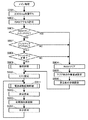
まず、図6を参照しつつ、メイン制御部100によって実行されるメイン処理について説明する。なお、このメイン処理は、パチンコ遊技機1の電源が投入されると開始され、メイン制御部100が起動している間、継続的に実行される。
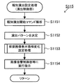
[Main processing by main control unit 100]
First, the main process executed by the main control unit 100 will be described with reference to FIG. This main process is started when the power of the pachinko gaming machine 1 is turned on, and is continuously executed while the main control unit 100 is activated.

図6のステップS901において、まず、CPU101は、例えば2000ms待機して、処理はステップS902に移る。なお、図示はしていないが、演出制御部400のCPU401は、パチンコ遊技機1の電源が投入されると、待機処理を行うことなく、メイン制御部100からの信号を受信可能な状態となる。すなわち、演出制御部400のCPU401は、メイン制御部100のCPU101よりも先に、処理を開始できる状態となる。   In step S901 in FIG. 6, first, the CPU 101 waits, for example, 2000 ms, and the process proceeds to step S902. Although not shown, when the power of the pachinko gaming machine 1 is turned on, the CPU 401 of the effect control unit 400 can receive a signal from the main control unit 100 without performing standby processing. . That is, the CPU 401 of the effect control unit 400 is in a state where processing can be started before the CPU 101 of the main control unit 100.

ステップS902において、CPU101は、RAM103へのアクセスが可能となり、処理はステップS903に移る。   In step S902, the CPU 101 can access the RAM 103, and the process proceeds to step S903.

ステップS903において、CPU101は、不図示のRAMクリアスイッチが「ON」であるか否かを判定する。ステップS903での判定がYESの場合、処理はステップS904に移り、この判定がNOの場合、処理はステップS907に移る。   In step S903, the CPU 101 determines whether or not a RAM clear switch (not shown) is “ON”. If the determination in step S903 is YES, the process proceeds to step S904. If the determination is NO, the process proceeds to step S907.

ステップS904において、CPU101は、RAMクリアを行う。ここで、RAMクリアは、公知の技術であるため詳細な説明は省略するが、RAM103に格納されている各種情報(例えば遊技状態を示す情報)を所定の初期状態とすることである。その後、処理はステップS905に移る。   In step S904, the CPU 101 clears the RAM. Here, the RAM clear is a well-known technique and will not be described in detail, but various information (for example, information indicating the gaming state) stored in the RAM 103 is set to a predetermined initial state. Thereafter, the process proceeds to step S905.

ステップS905において、CPU101は、RAMクリア時の作業領域を設定し、処理はステップS906に移る。   In step S905, the CPU 101 sets a work area when the RAM is cleared, and the process proceeds to step S906.

ステップS906において、CPU101は、周辺部の初期設定を行う。ここで、周辺部とは、演出制御部400や払出制御部300等である。周辺部の初期設定は、それぞれの制御部に対して、初期設定の実行を指示する初期設定コマンドを送信することによって行われる。その後、処理はステップS910に移る。   In step S906, the CPU 101 performs initial setting of the peripheral portion. Here, the peripheral portion is the effect control unit 400, the payout control unit 300, or the like. Initial setting of the peripheral unit is performed by transmitting an initial setting command for instructing execution of the initial setting to each control unit. Thereafter, the process proceeds to step S910.

ステップS907において、CPU101は、バックアップフラグが「ON」であるか否かを判定する。なお、バックアップフラグとは、電源遮断時にバックアップデータの生成が正常に完了した場合、オンになるフラグであり、生成したバックアップデータに関連付けて、当該バックアップデータが有効であることを示すフラグである。ステップS907での判定がYESの場合、処理はステップS908に移り、この判定がNOの場合、処理はステップS904に移る。   In step S907, the CPU 101 determines whether or not the backup flag is “ON”. Note that the backup flag is a flag that is turned on when the generation of backup data is normally completed when the power is turned off, and is a flag indicating that the backup data is valid in association with the generated backup data. If the determination in step S907 is YES, the process moves to step S908. If the determination is NO, the process moves to step S904.

ステップS908において、CPU101は、チェックサムが正常であるか否かを判定する。ステップS908での判定がYESの場合、処理はステップS909に移り、この判定がNOの場合、処理はステップS904に移る。   In step S908, the CPU 101 determines whether the checksum is normal. If the determination in step S908 is YES, the process proceeds to step S909. If the determination is NO, the process proceeds to step S904.

ステップS909において、CPU101は、後述する復旧処理(図8参照)を実行し、処理はステップS910に移る。   In step S909, the CPU 101 executes a recovery process (see FIG. 8) described later, and the process proceeds to step S910.

ステップS910において、CPU101は、内蔵されているCTC(タイマカウンタ)の周期(4ms)を設定する。なお、CPU101は、ここで設定された周期を用いて後述するタイマ割込処理(図9参照)を実行する。その後、処理はステップS911に移る。   In step S910, the CPU 101 sets a cycle (4 ms) of a built-in CTC (timer counter). Note that the CPU 101 executes a timer interrupt process (see FIG. 9), which will be described later, using the period set here. Thereafter, the process proceeds to step S911.

ステップS911において、CPU101は、後述する電源遮断監視処理(図7参照)を実行し、処理はステップS912に移る。   In step S911, the CPU 101 executes a power shutdown monitoring process (see FIG. 7) described later, and the process proceeds to step S912.

ステップS912において、CPU101は、タイマ割込処理の割り込みを禁止する設定を行い、処理はステップS913に移る。   In step S912, the CPU 101 performs setting to prohibit interruption of the timer interrupt process, and the process proceeds to step S913.

ステップS913において、CPU101は、各種の初期値乱数を更新し(カウントアップし)、処理はステップS914に移る。ここで、初期値乱数とは、後述するタイマ割り込み処理(図9参照)においてカウントアップ更新される各種の乱数(大当り乱数、図柄乱数、リーチ乱数、変動パターン乱数)の開始値を決定するための乱数であり、各種の乱数に対応して複数の初期値乱数が用意されている。なお、初期値乱数は、所定のCTCの周期(4ms)ごとに発生するタイマ割込み処理(図9参照)と、その残余時間(すなわち、この所定のCTCの周期からタイマ割込み処理に要する処理時間を減じた時間)に処理されるメイン処理(図6参照)の両方でカウントアップ更新され、設定されている乱数の最大値(例えば299)に達した後は再び最小値(例えば0)に戻る。また、この残余時間は、CPU101の処理状況に応じて異なるので、ランダムな時間となっており、残余時間で更新される初期値乱数の更新回数もランダムとなる。一方、詳細は後述するが、他の各種乱数(大当り乱数、図柄乱数、リーチ乱数、変動パターン乱数)は、タイマ割込み処理(図9参照)でしか更新されないため、初期値乱数とは乱数更新処理の処理周期が相違する。このように、処理周期が相違することにより、例えば、初期値乱数と大当り乱数の乱数範囲が同じ(例えば0〜299)であったとしても、大当り乱数の開始値として取得される初期値乱数の値は毎回ランダムとなる。そのため、大当りを発生させる大当り乱数値が取得されるタイミングを予測することを困難にすることができる。   In step S913, the CPU 101 updates (counts up) various initial value random numbers, and the process proceeds to step S914. Here, the initial value random number is used to determine the start value of various random numbers (hit random number, symbol random number, reach random number, variation pattern random number) that are counted up and updated in timer interrupt processing (see FIG. 9) described later. A plurality of initial value random numbers corresponding to various random numbers are prepared. The initial value random number includes a timer interrupt process (see FIG. 9) that occurs every predetermined CTC period (4 ms) and the remaining time (that is, the processing time required for the timer interrupt process from the predetermined CTC period). It is counted up and updated both in the main process (see FIG. 6) processed during the subtracted time and returns to the minimum value (for example, 0) again after reaching the maximum value (for example, 299) of the set random number. Further, since this remaining time varies depending on the processing status of the CPU 101, it is a random time, and the number of updates of the initial random number that is updated with the remaining time is also random. On the other hand, although details will be described later, other random numbers (big hit random numbers, design random numbers, reach random numbers, fluctuation pattern random numbers) are updated only by timer interrupt processing (see FIG. 9). The processing cycle is different. In this way, due to the difference in processing cycle, for example, even if the random number range of the initial value random number and the big hit random number is the same (for example, 0 to 299), the initial value random number acquired as the start value of the big hit random number The value is random every time. Therefore, it is possible to make it difficult to predict the timing at which the big hit random number value that generates the big hit is acquired.

ステップS914において、CPU101は、タイマ割込処理の割り込みを許可する設定を行い、処理がステップS911に戻される。すなわち、CPU101は、ステップS911〜S914の処理を繰り返し実行する。   In step S914, the CPU 101 performs setting to permit interruption of the timer interrupt process, and the process returns to step S911. That is, the CPU 101 repeatedly executes the processes of steps S911 to S914.

[メイン制御部100による電源遮断監視処理]
図7は、図6のステップS911における電源遮断監視処理の詳細フローチャートである。図7のステップS9111において、CPU101は、割込処理を禁止し、処理はステップS9112に移る。
[Power-off monitoring process by the main control unit 100]
FIG. 7 is a detailed flowchart of the power-off monitoring process in step S911 in FIG. In step S9111, the CPU 101 prohibits the interrupt process, and the process proceeds to step S9112.

ステップS9112において、CPU101は、不図示の電源部から電源遮断信号が入力されたか否かに基づいて、パチンコ遊技機1に対する電源供給が遮断されたか否かを判定する。ステップS9112での判定がYESの場合、処理はステップS9114に移り、この判定がNOの場合、処理はステップS9113に移る。   In step S9112, the CPU 101 determines whether the power supply to the pachinko gaming machine 1 is cut off based on whether a power cut-off signal is input from a power supply unit (not shown). If the determination in step S9112 is YES, the process moves to step S9114. If the determination is NO, the process moves to step S9113.

ステップS9113において、CPU101は、割込処理を許可し、電源遮断監視処理を終了する(処理は図6のステップS912に移る)。   In step S9113, the CPU 101 permits the interrupt process and ends the power shutdown monitoring process (the process moves to step S912 in FIG. 6).

一方、ステップS9114において、CPU101は、CPU101に対して各種情報が入出力される出力ポートをクリアし、処理はステップS9115に移る。   On the other hand, in step S9114, the CPU 101 clears the output port through which various information is input / output to / from the CPU 101, and the process proceeds to step S9115.

ステップS9115において、CPU101は、現在の遊技機1の遊技状態等に基づいて、バックアップデータをRAM103に作成後、RAM103の内容からチェックサムを作成してRAM103に格納する。なお、この処理は、メイン制御部100に供給される電源の電源遮断により電源電圧が低下し始めたことを検出してから(ステップS9112で「YES」と判定されてから)電源電圧が「0」になるまでの期間に行われる。この処理によって、電源が遮断される直前の遊技状態情報等がRAM103に記憶される。その後、処理はステップS9116に移る。   In step S 9115, the CPU 101 creates backup data in the RAM 103 based on the current gaming state of the gaming machine 1, creates a checksum from the contents of the RAM 103, and stores the checksum in the RAM 103. In this process, the power supply voltage is set to “0” after detecting that the power supply voltage has started to decrease due to the power supply cutoff of the power supplied to the main control unit 100 (after “YES” is determined in step S9112). It is done during the period until it becomes. Through this process, game state information and the like immediately before the power is turned off are stored in the RAM 103. Thereafter, the process proceeds to step S9116.

ステップS9116において、CPU101は、バックアップフラグを「ON」に設定し、処理はステップS9117に移る。   In step S9116, the CPU 101 sets the backup flag to “ON”, and the process proceeds to step S9117.

ステップS9117において、CPU101は、RAM103へのアクセスを禁止し、電源遮断監視処理を終了する(処理は図6のステップS912に移る)。   In step S 9117, the CPU 101 prohibits access to the RAM 103 and ends the power shutdown monitoring process (the process moves to step S 912 in FIG. 6).

[メイン制御部100による復旧処理]
図8は、図6のステップS909における復旧処理の詳細フローチャートである。まず、図9のステップS9091において、CPU101は、復旧時におけるRAM103の作業領域を設定し、処理はステップS9092に移る。
[Restoration process by main control unit 100]
FIG. 8 is a detailed flowchart of the recovery process in step S909 of FIG. First, in step S9091 of FIG. 9, the CPU 101 sets a work area of the RAM 103 at the time of restoration, and the process proceeds to step S9092.

ステップS9092において、CPU101は、RAM103の情報を参照して、電源遮断時における遊技状態や特別図柄抽選の保留数に関する情報を確認し、当該情報を含めた復旧通知コマンドを演出制御部400に対して送信する。このように、CPU101は、パチンコ遊技機1に対する電源供給が復旧したことを通知するために、電源遮断時の状態を示す復旧通知コマンドを演出制御部400へ送信する。このステップS9092の処理により、演出制御部400は、電源遮断前の遊技状態等を確認することができる。   In step S9092, the CPU 101 refers to the information in the RAM 103, confirms information regarding the gaming state at the time of power-off and the number of special symbol lotteries held, and sends a recovery notification command including the information to the effect control unit 400. Send. As described above, the CPU 101 transmits a recovery notification command indicating the power-off state to the effect control unit 400 in order to notify that the power supply to the pachinko gaming machine 1 has been recovered. By the processing in step S9092, the effect control unit 400 can check the gaming state before power-off and the like.

ステップS9093において、CPU101は、周辺部の設定を行い、処理はステップS9094に移る。   In step S9093, the CPU 101 sets a peripheral part, and the process proceeds to step S9094.

ステップS9094において、CPU101は、バックアップフラグを「OFF」に設定し、復旧処理を終了する(処理は図6のステップS910に移る)。   In step S9094, the CPU 101 sets the backup flag to “OFF” and ends the recovery process (the process moves to step S910 in FIG. 6).

[メイン制御部のタイマ割り込み処理]
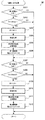
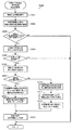
次に、メイン制御部100において実行されるタイマ割込処理について説明する。図9は、メイン制御部100によって行われるタイマ割込み処理の一例を示すフローチャートである。以下に、図9を参照して、メイン制御部100において行われるタイマ割込み処理について説明する。メイン制御部100は、電源投入時や電源断時等の特殊な場合を除く通常の動作時において、図9に示す一連の処理を一定時間(4ミリ秒)毎に繰り返し実行する。なお、図9以降のフローチャートに基づいて説明するメイン制御部100で行われる処理は、ROM102に記憶されているプログラムに基づいて実行される。
[Timer interrupt processing of main control unit]
Next, a timer interrupt process executed in the main control unit 100 will be described. FIG. 9 is a flowchart illustrating an example of timer interrupt processing performed by the main control unit 100. The timer interrupt process performed in the main control unit 100 will be described below with reference to FIG. The main control unit 100 repeatedly executes a series of processes shown in FIG. 9 at regular time intervals (4 milliseconds) during normal operation except for special cases such as when the power is turned on or when the power is turned off. Note that the processing performed by the main control unit 100 described based on the flowcharts of FIG. 9 and subsequent figures is executed based on a program stored in the ROM 102.

まず、ステップS1において、メイン制御部100のCPU101は、大当り乱数、図柄乱数、リーチ乱数、及び変動パターン乱数等の各種の乱数の更新、および各乱数がカウントアップ更新される際の開始値となるそれぞれの初期値乱数の更新を行う乱数更新処理を実行する。ここで、大当り乱数は、特別図柄抽選の当選又は落選を判定する(つまり、特別図柄抽選を行う)ための乱数である。図柄乱数は、特別図柄抽選に当選した場合に大当りの種類を決定するための乱数である。大当り乱数及び図柄乱数は、後に説明する図13のステップS407の処理で使用される乱数である。リーチ乱数は、特別図柄抽選に落選した場合にリーチ演出を行うか否かを決定するための乱数である。変動パターン乱数は、特別図柄の変動時間(変動パターン)を決定するための乱数である。ここで、特別図柄の変動時間は、この特別図柄の変動に同期して実行される報知演出(変動演出)の実行時間と等しい。リーチ乱数及び変動パターン乱数は、後に説明する図13のステップS408の処理で使用される。ステップS1の乱数更新処理において、大当り乱数、図柄乱数、リーチ乱数、及び変動パターン乱数等は、それぞれ、1ずつ加算されて更新される。つまり、カウントアップされる。そして、ステップS2の始動口スイッチ(SW)処理やステップS3のゲートスイッチ(SW)処理において各乱数が取得されて、後述するステップS4の特別図柄処理やステップS5の普通図柄処理で使用される。なお、このステップS1の処理を行うカウンタは、典型的にはループカウンタであり、設定されている乱数の最大値(例えば変動パターン乱数では299)に達した後は再び0に戻る(つまり、循環する)。また、ステップS1の乱数更新処理において、大当り乱数、図柄乱数、リーチ乱数、及び変動パターン乱数等の各カウンタは、それぞれ、ループカウンタのカウントが一巡すると、その時点での各乱数に対応する初期値乱数を取得して、当該初期値乱数の値を開始値として、新たにループカウンタのカウントを開始する。なお、大当り乱数、図柄乱数、リーチ乱数、及び変動パターン乱数等の乱数範囲は、任意に設定すればよいが、それぞれを異なる範囲に設定することで、これらの乱数の間でカウンタの値(カウント値)が同期しないように設定することが好ましい。   First, in step S1, the CPU 101 of the main control unit 100 serves as a starting value for updating various random numbers such as jackpot random numbers, symbol random numbers, reach random numbers, and variation pattern random numbers, and counting up each random number. Random number update processing for updating each initial value random number is executed. Here, the big hit random number is a random number for determining whether or not a special symbol lottery is won or lost (that is, performing a special symbol lottery). The symbol random number is a random number for determining the type of jackpot when the special symbol lottery is won. The jackpot random number and the design random number are random numbers used in the process of step S407 in FIG. The reach random number is a random number for determining whether or not a reach effect is performed when a special symbol lottery is lost. The variation pattern random number is a random number for determining the variation time (variation pattern) of the special symbol. Here, the variation time of the special symbol is equal to the execution time of the notification effect (variation effect) executed in synchronization with the variation of the special symbol. The reach random number and the fluctuation pattern random number are used in the process of step S408 in FIG. 13 described later. In the random number update process of step S1, the big hit random number, the design random number, the reach random number, the variation pattern random number, etc. are each added and updated by one. That is, it is counted up. Each random number is acquired in the start port switch (SW) process in step S2 and the gate switch (SW) process in step S3, and is used in the special symbol process in step S4 and the normal symbol process in step S5 described later. Note that the counter that performs the processing of step S1 is typically a loop counter, and returns to 0 again after reaching the maximum value of the set random number (for example, 299 for the variation pattern random number) (that is, the circulation counter). To do). In addition, in the random number update process of step S1, each counter such as a big hit random number, a design random number, a reach random number, and a variation pattern random number is initialized to an initial value corresponding to each random number at that time when the loop counter counts once. A random number is acquired, and the loop counter is newly started using the initial random number as a start value. The random number ranges such as jackpot random numbers, design random numbers, reach random numbers, and fluctuation pattern random numbers may be set arbitrarily, but by setting each to a different range, the counter value (count) (Value) is preferably set so as not to synchronize.

次に、ステップS2において、CPU101は、第1始動口スイッチ111a及び第2始動口スイッチ111bの状態を監視し、第1始動口21又は第2始動口22に遊技球が入賞したと判定した時点で、第1特別図柄抽選の保留数U1や第2特別図柄抽選の保留数U2に関する処理や各種乱数を取得する処理を行う始動口スイッチ処理を実行する。この始動口スイッチ処理の詳細については、図12を参照して後に詳述する。   Next, in step S2, the CPU 101 monitors the state of the first start port switch 111a and the second start port switch 111b, and determines that a game ball has won the first start port 21 or the second start port 22. Thus, the start port switch process is executed to perform processing related to the number of holdings U1 for the first special symbol lottery, the number of holdings U2 for the second special symbol lottery, and processing for obtaining various random numbers. Details of the start port switch process will be described later with reference to FIG.

次に、ステップS3において、CPU101は、ゲートスイッチ113の状態を監視し、ゲートスイッチ113からの出力信号に基づいて、ゲート25を遊技球が通過したと判定された時点で普通図柄抽選の保留数が上限値(例えば4)未満か否かを判断し、保留数が上限値未満であると判断した場合、後述するステップS5の普通図柄処理に使用される乱数を取得するゲートスイッチ処理を実行する。   Next, in step S3, the CPU 101 monitors the state of the gate switch 113 and, based on the output signal from the gate switch 113, determines that the game ball has passed through the gate 25. Is determined to be less than the upper limit value (for example, 4), and if it is determined that the number of holds is less than the upper limit value, a gate switch process for acquiring a random number used in the normal symbol process in step S5 described later is executed. .

次に、ステップS4において、CPU101は、第1特別図柄抽選又は第2特別図柄抽選を実行し、第1特別図柄表示器4a又は第2特別図柄表示器4bに特別図柄を変動表示させた後にこれらの抽選結果を示す停止図柄の表示処理や、演出制御部400へ各種コマンドを送信等するための特別図柄処理を実行する。この特別図柄処理については、図13を参照して後に詳述する。   Next, in step S4, the CPU 101 executes the first special symbol lottery or the second special symbol lottery, and after the special symbols are variably displayed on the first special symbol display 4a or the second special symbol display 4b, these are displayed. The stop symbol display process showing the lottery result of the above and the special symbol process for transmitting various commands to the effect control unit 400 are executed. This special symbol process will be described in detail later with reference to FIG.

次に、ステップS5において、CPU101は、ステップS3のゲートスイッチ処理で取得された乱数が所定の当り乱数と一致するか否かを判定する普通図柄処理を実行する。そして、CPU101は、普通図柄表示器4eに普通図柄を変動表示させた後に判定結果を示す普通図柄を停止表示させる。具体的には、CPU101は、普通図柄を変動表示させた後に停止表示させる普通図柄変動時間を、非時短状態では10秒に設定し、時短状態では0.5秒に短縮する。また、CPU101は、普通図柄表示器4eに表示された普通図柄が所定の当り図柄となる確率(つまり、普通図柄抽選の当選確率)を、非電サポ状態では低確率(1/10)に設定し、電サポ状態では高確率(10/10)に上昇させる。   Next, in step S5, the CPU 101 executes a normal symbol process for determining whether or not the random number acquired in the gate switch process in step S3 matches a predetermined hit random number. Then, the CPU 101 stops and displays the normal symbol indicating the determination result after the normal symbol is variably displayed on the normal symbol display 4e. Specifically, the CPU 101 sets the normal symbol change time to be stopped and displayed after the normal symbol is variably displayed to 10 seconds in the non-time-short state and to 0.5 seconds in the time-short state. In addition, the CPU 101 sets the probability that the normal symbol displayed on the normal symbol display 4e becomes a predetermined winning symbol (that is, the winning probability of the normal symbol lottery) at a low probability (1/10) in the non-electric support state. However, in the electric support state, it is raised with a high probability (10/10).

次に、ステップS6において、CPU101は、ステップS4の特別図柄処理で特別図柄抽選に当選したと判定された場合(大当りした場合)に、大入賞口開閉部115を制御して大入賞口23に所定の開閉動作を行わせ、また、いわゆる大当り遊技演出等に関する各種コマンドを演出制御部400に対して送信等するための大入賞口処理を実行する。この処理によって、大当り遊技(特別遊技)が進行され、遊技者は多量の賞球を獲得可能となる。この大入賞口処理については、図18及び図19を参照して後に詳述する。   Next, in step S6, when it is determined that the special symbol lottery is won in the special symbol processing in step S4 (when a big hit is made), the CPU 101 controls the big prize opening / closing unit 115 to the special prize lot 23. A predetermined opening / closing operation is performed, and a big prize opening process for transmitting various commands related to a so-called jackpot game effect or the like to the effect control unit 400 is executed. By this processing, the big hit game (special game) is progressed, and the player can acquire a large amount of prize balls. This special winning opening process will be described in detail later with reference to FIGS.

次に、ステップS7において、CPU101は、ステップS5の普通図柄処理によって普通図柄表示器4eに表示された普通図柄が所定の当り図柄である場合(つまり、普通図柄抽選に当選した場合)に、電動チューリップ27を作動させる電動チューリップ処理を実行する。その際、CPU101は、非電サポ状態では電動チューリップ27を極短期間(0.10秒間を1回)開放制御し、電サポ状態では電動チューリップ27を長期間(2.00秒間を3回)開放制御する。なお、電動チューリップ27が開放状態に制御されることによって第2始動口22に遊技球が入賞可能な状態となり、第2始動口22に遊技球が入賞することで、第2特別図柄抽選が行われることとなる。   Next, in step S7, the CPU 101 performs electric driving when the normal symbol displayed on the normal symbol display 4e by the normal symbol processing in step S5 is a predetermined winning symbol (that is, when the normal symbol lottery is won). An electric tulip process for operating the tulip 27 is executed. At that time, the CPU 101 controls the opening of the electric tulip 27 for a very short period (once for 0.10 seconds) in the non-electric support state, and the electric tulip 27 for a long period (three times for 2.00 seconds) in the electric support state. Open control. In addition, when the electric tulip 27 is controlled to be in the open state, a game ball can be won at the second start port 22, and when the game ball wins at the second start port 22, a second special symbol lottery is performed. Will be.

次に、ステップS8において、CPU101は、遊技球の入賞個数の管理及び入賞に応じた賞球の払出しを制御する賞球処理を実行する。   Next, in step S <b> 8, the CPU 101 executes prize ball processing for managing the number of winning game balls and controlling the payout of prize balls according to the prize.

次に、ステップS9において、CPU101は、ステップS2の始動口スイッチ処理、ステップS4の特別図柄処理、ステップS6の大入賞口処理、ステップS8の賞球処理等でRAM103にセットされた各種コマンドや演出に必要な情報を演出制御部400又は払出制御部300へ出力する出力処理を実行する。なお、CPU101は、第1始動口21、第2始動口22、大入賞口23、普通入賞口24に遊技球が入賞する毎に、それぞれの入賞口に遊技球が入賞したことを通知するための入賞コマンドをRAM103にセットして、当該入賞コマンドを演出制御部400又は払出制御部300へ出力する。   Next, in step S9, the CPU 101 executes various commands and effects set in the RAM 103 by the start opening switch process in step S2, the special symbol process in step S4, the big winning opening process in step S6, the prize ball process in step S8, and the like. Output processing for outputting information necessary for the production control unit 400 or the payout control unit 300 is executed. The CPU 101 notifies each winning opening that a gaming ball has won each time the gaming ball wins the first starting opening 21, the second starting opening 22, the big winning opening 23, and the normal winning opening 24. Are set in the RAM 103, and the winning command is output to the effect control unit 400 or the payout control unit 300.

[制御時間カウント処理について]
ここで、図9を用いて上述したタイマ割り込み処理では説明を省略したが、このタイマ割り込み処理において、CPU101は、特別図柄ゲーム側の一連の制御時間を1つのタイマ機能を用いて計測する特別図柄ゲーム側の制御時間カウント処理(「特図ゲームカウント処理」という)、および、普通図柄ゲーム側の一連の制御時間を1つのタイマ機能を用いて計測する普通図柄ゲーム側の制御時間カウント処理(「普図ゲームカウント処理」という)を実行する。特図ゲームカウント処理および普図ゲームカウント処理は、例えば、図9のステップS7の処理とステップS8の処理との間に、順番に実行される。なお、特別図柄ゲームは、始動口(21又は22)への遊技球の入賞を待機し、遊技球が入賞したことに応じて特別図柄抽選を実行してその抽選結果を報知することを繰り返し、特別図柄抽選に当選した場合には大当り遊技を実行するゲームである。また、普通図柄ゲームは、ゲート25への遊技球の通過を待機し、遊技球が通過したことに応じて普通図柄抽選を実行してその抽選結果を報知することを繰り返し、普通図柄抽選に当選した場合には電動チューリップ27の開閉制御(電チューの開放遊技)を実行するゲームである。
[About control time count processing]
Here, the description of the timer interrupt process described above with reference to FIG. 9 is omitted, but in this timer interrupt process, the CPU 101 uses a single timer function to measure a series of control times on the special symbol game side. Control time count processing on the game side (referred to as “special game count processing”), and control time count processing on the normal symbol game side that measures a series of control times on the normal symbol game side using one timer function (“ The usual game count process ”is executed. For example, the special game count process and the normal game count process are executed in order between the process of step S7 and the process of step S8 in FIG. In addition, the special symbol game waits for the winning of the game ball to the start opening (21 or 22), repeatedly executes the special symbol lottery in response to the winning of the game ball, and notifies the lottery result, When the special symbol lottery is won, the game is a big hit game. The normal symbol game waits for the game ball to pass to the gate 25, repeats the normal symbol lottery according to the passing of the game ball and informs the lottery result, and wins the normal symbol lottery. In this case, the opening / closing control of the electric tulip 27 (electric chew opening game) is executed.

以下では、まず、特図ゲームカウント処理について説明する。図10は、特図ゲームカウント処理および普図ゲームカウント処理を実行する際に使用されるデータ、および、メイン制御部100のRAM103の記憶エリア(作業エリア)について説明するための図である。   In the following, first, the special game count process will be described. FIG. 10 is a diagram for explaining data used when executing the special game count process and the normal game count process, and the storage area (work area) of the RAM 103 of the main control unit 100.

図10(1)は、特別図柄ゲーム側のカウント対象の時間を設定(特定)するためのデータ(「特図側設定データ」という)の種類を示している。特図側設定データは、特別図柄ゲームの各期間(時間)のうち何れの期間を計測しているのかを設定するためのデータである。この特別図柄ゲームの各期間(時間)には、図10(1)に示すように、「始動口入賞待ち中」と、「特別図柄変動表示中」と、「特別図柄停止表示中」と、「オープニング表示中」と、「ラウンド中」と、「大入賞口有効期間中」と、「エンディング表示中」とが含まれる。   FIG. 10A shows the types of data (referred to as “special drawing side setting data”) for setting (specifying) the time to be counted on the special symbol game side. The special figure side setting data is data for setting which period of each period (time) of the special symbol game is measured. In each period (time) of this special symbol game, as shown in FIG. 10 (1), “Waiting for start opening prize”, “Displaying special symbol variation”, “Displaying special symbol stop”, "Opening display", "Rounding", "Large winning slot validity period", and "Ending display" are included.

「始動口入賞待ち中」は、始動口入賞が有ると即時にこの始動口入賞に係る特別図柄抽選を実行して特別図柄の変動表示を開始できる状態(期間)であり、典型的には、大当り遊技中ではなく、特別図柄の変動表示中でも規定時間の停止表示中でもない状態である。「特別図柄変動表示中」は、始動口入賞に応じて特別図柄抽選を実行して表示器4に特別図柄の変動表示を実行している状態(期間)である。「特別図柄停止表示中」は、表示器4に変動表示していた特別図柄を特別図柄抽選結果を報知する表示態様で規定時間(0.5秒間)完全に停止表示している状態(期間)である。「オープニング表示中」は、特別図柄抽選に当選して画像表示部6に大当り遊技が開始したことを報知するオープニング演出を表示している状態(期間)である。「ラウンド中」は、大当り遊技において大入賞口23が開放されるラウンド(ラウンド遊技)を実行している状態(期間)である。「大入賞口有効期間中」は、各ラウンドの直後に配置され、ラウンドが終了して大入賞口23が閉塞されたにも関わらず遊技球の大入賞口23への入賞を有効と認める期間であり、これによって、いわゆるオーバー入賞が認められることとなる(図18及び図19を用いて後に詳述する大入賞口処理では、説明の簡単のため、オーバー入賞の処理内容は省略している)。なお、ラウンド中の期間および大入賞口有効期間を除く期間においては、遊技球の大入賞口23への入賞は有効と認められない。「エンディング表示中」は、画像表示部6に大当り遊技が終了することを報知するエンディング演出を表示している状態(期間)である。   “Waiting for start entrance prize” is a state (period) in which a special symbol lottery related to the start entrance prize can be immediately executed to start displaying the variation of the special design when there is a start entrance prize. It is not a big hit game, and it is in a state where neither a special symbol change display nor a specified time stop display is displayed. “During special symbol variation display” is a state (period) in which special symbol lottery is executed according to the start opening winning and the special symbol variation display is performed on the display 4. “During special symbol stop display” is a state (period) in which the special symbol variably displayed on the display unit 4 is completely stopped and displayed for a specified time (0.5 seconds) in a display mode for notifying the special symbol lottery result. It is. “Opening display” is a state (period) in which an opening effect is displayed on the image display unit 6 informing that the special symbol lottery is won and that the big hit game has started. “During round” is a state (period) in which a round (round game) in which the big winning opening 23 is opened in the big hit game is being executed. “During the grand prize winning period” is a period of time that is arranged immediately after each round, and that the winning of the game ball to the big prize opening 23 is recognized as being valid despite the end of the round and the closing of the big prize opening 23 Thus, a so-called over-winning is recognized (in the big winning opening process described in detail later with reference to FIG. 18 and FIG. 19, the processing content of the over-winning is omitted for the sake of simplicity). ). In addition, in the period excluding the period during the round and the grand prize winning period, the winning of the game ball to the big prize opening 23 is not recognized as valid. “During ending display” is a state (period) in which an ending effect is displayed on the image display unit 6 to notify the end of the big hit game.

図10(1)に示すように、例えば、特図側設定データ「00H」は「始動口入賞待ち中」であることを設定するデータであり、例えば、特図側設定データ「01H」は「特別図柄変動表示中」であることを設定するデータである。なお、これらの特図側設定データは、ROM102に記憶されている。   As shown in FIG. 10 (1), for example, the special figure side setting data “00H” is data for setting “waiting for start opening prize”, for example, the special figure side setting data “01H” is “ This is data for setting “special symbol variation display”. These special figure side setting data are stored in the ROM 102.

図10(3)は、RAM103の記憶エリア(作業エリア)の模式図である。図10(3)に示すように、RAM103の記憶エリアには、カウント対象時間設定エリア10と、時間カウントエリア11と、単純変動表示用時間カウントエリア12とが含まれている。カウント対象時間設定エリア10は、特別図柄ゲーム側のカウント対象時間設定エリア10A(「エリア10A」という)と、普通図柄ゲーム側のカウント対象時間設定エリア10B(「エリア10B」という)とから成る。時間カウントエリア11は、特別図柄ゲーム側の時間カウントエリア11A(「エリア11A」という)と、普通図柄ゲーム側の時間カウントエリア11B(「エリア11B」という)とから成る。単純変動表示用時間カウントエリア12は、特別図柄ゲーム側の単純変動表示用時間カウントエリア12A(「エリア12A」という)と、普通図柄ゲーム側の単純変動表示用時間カウントエリア12B(「エリア12B」という)とから成る。   FIG. 10 (3) is a schematic diagram of a storage area (work area) of the RAM 103. As shown in FIG. 10 (3), the storage area of the RAM 103 includes a count target time setting area 10, a time count area 11, and a simple variation display time count area 12. The count target time setting area 10 includes a count target time setting area 10A (referred to as “area 10A”) on the special symbol game side and a count target time setting area 10B (referred to as “area 10B”) on the normal symbol game side. The time count area 11 includes a time count area 11A (referred to as “area 11A”) on the special symbol game side and a time count area 11B (referred to as “area 11B”) on the normal symbol game side. The simple variation display time count area 12 includes a special symbol display time count area 12A (referred to as "Area 12A") on the special symbol game side and a simple variation display time count area 12B ("Area 12B") on the normal symbol game side. Said).

エリア11Aは、上記した特別図柄ゲームの各期間(「特別図柄変動表示中」等)についての時間経過を計測するためのタイマエリアであり、1つの時間データを書き込んで1つの時間経過について計測するためのタイマエリアである。エリア10Aは、図10(1)を用いて説明した特図側設定データの何れか1つが書き込まれることによって、エリア11Aで計測する時間の種類を設定するためのエリアである。エリア12Aは、第1特別図柄表示器4a(又は第2特別図柄表示器4b)に特別図柄が7セグ表示で変動表示される際に、この7セグ表示の3つの表示態様を48ミリ秒毎に順番に切替えて循環表示させる制御を実行するにあたって、この48ミリ秒の時間経過を計測するためのタイマエリアであり、1つの時間データを書き込んで1つの時間経過について計測するためのタイマエリアである。なお、上記の7セグ表示の3つの表示態様は、例えば、数字の0を示す表示態様と、数字の7を示す表示態様と、7つのセグ全てが消灯した表示態様である。   Area 11A is a timer area for measuring the passage of time for each period of the above-described special symbol game (such as “special symbol variation display”), and measures one passage of time by writing one piece of time data. This is a timer area. The area 10A is an area for setting the type of time to be measured in the area 11A by writing any one of the special drawing side setting data described with reference to FIG. When the special symbol is variably displayed in the 7-segment display on the first special symbol display 4a (or the second special symbol display 4b), the area 12A displays the three display modes of the 7-segment display every 48 milliseconds. This is a timer area for measuring the time lapse of 48 milliseconds when executing the control for switching and displaying in order, and a timer area for measuring one lapse of time by writing one time data. is there. Note that the three display modes of the 7-segment display are, for example, a display mode that indicates the number 0, a display mode that indicates the number 7, and a display mode in which all seven segments are turned off.

CPU101は、エリア10Aに特図側設定データを書き込むことでエリア11Aによる計測対象の期間(時間)の種類を設定すると共に、エリア11Aに計測する時間データを書き込み、図9のタイマ割込み処理において4ミリ秒毎に実行される特図ゲームカウント処理によってエリア11Aの時間データの値を1ずつ減算することで、1つのタイマ領域(エリア11A)を順番に用いて特別図柄ゲームの各期間の経過を順番に計測する。   The CPU 101 sets the type of period (time) to be measured by the area 11A by writing the special setting side setting data in the area 10A, and writes the time data to be measured in the area 11A. In the timer interrupt process of FIG. By subtracting the time data value of the area 11A by 1 by the special figure game count process executed every millisecond, the progress of each period of the special symbol game is sequentially performed using one timer area (area 11A). Measure in order.

また、CPU101は、エリア11Aで特別図柄変動表示の時間が計測されているときには、エリア12Aに所定の時間データ(「12」)を書き込んで、図9のタイマ割込み処理において4ミリ秒毎に実行される特図ゲームカウント処理によってエリア12Aの時間データの値を1ずつ減算して0になると再び所定の時間データ(「12」)を書き込むと共に特別図柄の表示態様を切替える。これにより、第1特別図柄表示器4a(又は第2特別図柄表示器4b)に特別図柄が7セグ表示で変動表示される際に、この7セグ表示の3つの表示態様が48ミリ秒毎に順番に切替わって循環表示されることとなる。   In addition, when the special symbol variation display time is measured in the area 11A, the CPU 101 writes predetermined time data ("12") in the area 12A and executes it every 4 milliseconds in the timer interrupt processing of FIG. When the value of the time data in the area 12A is subtracted by 1 by the special figure game count process to be 0, the predetermined time data ("12") is written again and the display mode of the special symbol is switched. As a result, when the special symbol is variably displayed in the 7-segment display on the first special symbol display 4a (or the second special symbol display 4b), the three display modes of the 7-segment display are changed every 48 milliseconds. It will be switched in order and displayed cyclically.

なお、図10(3)では、一例として、エリア10Aに「01H」が書き込まれていることによって、エリア11Aにおいて特別図柄変動表示の時間経過が計測されることを設定している。また、図10(3)のエリア11Aには、一例として、時間を示す値「2500」が書き込まれているが、この値は図9のタイマ割り込み処理によって4ミリ秒毎に1減算されて更新されるので、この値「2500」は10.000秒を示している。また、図10(3)のエリア12Aには、一例として、時間を示す値「12」が書き込まれているが、この値も同様に図9のタイマ割り込み処理によって4ミリ秒毎に1減算されて更新されるので、この値「12」は48ミリ秒を示している。   In FIG. 10 (3), as an example, it is set that “01H” is written in the area 10A, whereby the elapsed time of the special symbol variation display is measured in the area 11A. In addition, as an example, a value “2500” indicating time is written in the area 11A of FIG. 10 (3). This value is updated by subtracting 1 every 4 milliseconds by the timer interrupt processing of FIG. Therefore, this value “2500” indicates 10.000 seconds. In addition, as an example, a value “12” indicating time is written in the area 12A of FIG. 10 (3). This value is also subtracted by 1 every 4 milliseconds by the timer interrupt processing of FIG. Therefore, this value “12” indicates 48 milliseconds.

以上のように、第1の実施形態によれば、特別図柄ゲームの一連の制御時間を1つのタイマ機能(図10(3)の11A参照)を用いて計測する。ここで、従来の遊技機においては、特別図柄ゲームを構成する各制御時間(特別図柄変動表示の制御時間、ラウンド実行の制御時間等)をそれぞれ個別のタイマ機能を用いて計測していたので、メイン制御部のRAMの記憶エリアに特別図柄ゲームを構成する制御時間毎に個別の時間カウントエリアを設けていた。一方、第1の実施形態では、上記のように特別図柄ゲームの一連の制御時間を1つのタイマ機能を用いて計測するので、演算負荷を効果的に低減することができる。また、第1の実施形態によれば、特別図柄変動表示の実行期間において特別図柄表示器4a(又は4b)に7セグ表示の3つの表示態様を48ミリ秒毎に順番に切替えて循環表示させる際の切替え時間の計測には、上記したタイマ機能(図10(3)の11A参照)とは別のタイマ機能(図10(3)の12A参照)を用いる。このことから、第1の実施形態によれば、演算処理の複雑化を効果的に抑制できる。   As described above, according to the first embodiment, a series of control times of a special symbol game is measured using one timer function (see 11A in FIG. 10 (3)). Here, in the conventional gaming machine, each control time (control time for special symbol variation display, control time for round execution, etc.) constituting the special symbol game was measured using an individual timer function. A separate time count area was provided for each control time constituting the special symbol game in the RAM storage area of the main control unit. On the other hand, in the first embodiment, as described above, the series of control times of the special symbol game is measured using one timer function, so that the calculation load can be effectively reduced. Further, according to the first embodiment, during the execution period of the special symbol variation display, the special symbol display 4a (or 4b) switches the three display modes of the 7-segment display in turn every 48 milliseconds and displays them cyclically. In order to measure the switching time, a timer function (see 12A in FIG. 10 (3)) different from the timer function (see 11A in FIG. 10 (3)) is used. From this, according to 1st Embodiment, the complexity of arithmetic processing can be suppressed effectively.

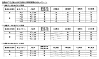
図11は、特別図柄変動表示の時間をエリア11Aに設定するために用いられる変動時間テーブルの概念図の一例である。この変動時間テーブルは、ROM102に記憶されており、RAM103に読み出されて使用される。図11に示すように、変動時間テーブルは、変動パターンの識別番号と、基本変動時間(秒)を示すデータと、加算変動時間(秒)を示すデータとから成る。変動パターンの識別番号は、図14〜図17を用いて後述する変動パターン決定テーブルHT1−1、HT1−2、HT2−1およびHT2−2に含まれる変動パターンを識別するための番号である。基本変動時間は、変動パターン(つまり、特別図柄変動時間)を構成する基本の変動時間である。加算変動時間は、変動パターンを構成する加算される変動時間である。基本変動時間と加算変動時間とを加算した時間が、変動パターン(図14〜図17参照)である。例えば、識別番号1に対応する変動パターンは、基本変動時間90秒に加算変動時間0.10秒を加算した90.10秒であり、例えば、識別番号21に対応する変動パターンは、基本変動時間8秒である。   FIG. 11 is an example of a conceptual diagram of a variation time table used for setting the special symbol variation display time in the area 11A. This variation time table is stored in the ROM 102 and read out to the RAM 103 for use. As shown in FIG. 11, the variation time table includes a variation pattern identification number, data indicating basic variation time (seconds), and data indicating addition variation time (seconds). The identification number of the variation pattern is a number for identifying the variation pattern included in the variation pattern determination tables HT1-1, HT1-2, HT2-1, and HT2-2, which will be described later with reference to FIGS. The basic variation time is a basic variation time constituting a variation pattern (that is, a special symbol variation time). The added fluctuation time is an added fluctuation time constituting a fluctuation pattern. A time obtained by adding the basic fluctuation time and the addition fluctuation time is a fluctuation pattern (see FIGS. 14 to 17). For example, the variation pattern corresponding to the identification number 1 is 90.10 seconds obtained by adding the addition variation time 0.10 seconds to the basic variation time 90 seconds. For example, the variation pattern corresponding to the identification number 21 is the basic variation time. 8 seconds.

CPU101は、図10(3)のエリア11Aで特別図柄変動表示の時間を計測する場合には、後述する図13のステップS408の処理で決定された変動パターンに対応する時間データ(「秒」の時間を示すデータ)を、RAM103の変動時間テーブル(図11)から読み出して、読み出した時間データに250を乗算して4ミリ秒周期で実行される時間計測処理に適応する時間データに変換し、変換した時間データをRAM103のエリア11Aに書き込む。例えば、識別番号1に対応する変動パターン「90.10秒」を示す時間データの値をエリア11Aに設定する場合には、RAM103の変動時間テーブルから基本変動時間90秒および加算変動時間0.10秒を示す時間データを読み出して加算し、この加算した時間データに250を乗算して4ミリ秒周期の演算処理に適応する時間データ「22525」に変換し、変換した時間データ「22525」をRAM103のエリア11Aに書き込む。なお、図11の変動時間テーブルの横には、参考のために、250を乗算して4ミリ秒周期の演算処理に適応させた時間データを記載しているが、250を乗算すると自然数ではなくなるものは(括弧書きの値を参照)、四捨五入により自然数に調整して処理している。   When measuring the special symbol variation display time in the area 11A of FIG. 10 (3), the CPU 101 determines the time data ("seconds") corresponding to the variation pattern determined in step S408 of FIG. (Time indicating data) is read from the fluctuation time table (FIG. 11) of the RAM 103, and the read time data is multiplied by 250 to be converted into time data adapted to time measurement processing executed in a cycle of 4 milliseconds, The converted time data is written in the area 11A of the RAM 103. For example, when the value of the time data indicating the variation pattern “90.10 seconds” corresponding to the identification number 1 is set in the area 11A, the basic variation time 90 seconds and the addition variation time 0.10 from the variation time table of the RAM 103. The time data indicating the second is read and added, and the added time data is multiplied by 250 to be converted into time data “22525” adapted to the arithmetic processing of a cycle of 4 milliseconds, and the converted time data “22525” is converted into the RAM 103. Is written in the area 11A. In addition, for reference, time data that is multiplied by 250 and adapted to a calculation process with a period of 4 milliseconds is described on the side of the variation time table in FIG. Things (see values in parentheses) are adjusted to natural numbers by rounding off.

以上のように、第1の実施形態によれば、ROM102に記憶されRAM103に読み出される変動時間テーブルの変動パターン(特別図柄変動時間)を示す時間データを「秒」の時間を示すデータ(つまり、除算値の時間データ;図11の基本変動時間の部分を参照)とし、特別図柄変動時間を設定する際に250を乗算して4ミリ秒周期の演算処理に適応する時間データ(つまり、乗算値の時間データ;図11の変動時間テーブルの右横の部分を参照)に変換する。このことから、第1の実施形態によれば、変動時間テーブルの特別図柄変動時間を示すデータを1バイト以下のデータ量に押さえられる場合があるので(図11の識別番号20〜24参照)、ROM102およびRAM103の使用メモリ領域を効果的に抑制することができる。また、第1の実施形態によれば、例えば特別図柄変動時間90.10秒のように、除算値の時間データで示してもデータ量が1バイトを超える特別図柄変動時間については、加算変動時間の時間データ(小数点以下の時間を示す時間データ)として分割して変動時間テーブルを構成させている(図11参照)。ここで、図11では、加算変動時間の部分のテーブルにおいて、説明の便宜上、同じ時間データ値を変動パターン毎にそれぞれ記載しているが、実際にはこのテーブルにおいて同じ時間データ値は、重複して記憶されず、1つだけ記憶されている。例えば、加算変動時間の部分のテーブルにおいて、0.01秒の時間データ値は、図11では説明の便宜上3つ記載しているが、実際は1つだけ記憶されている。このことから、第1の実施形態によれば、ROM102およびRAM103の使用メモリ領域を効果的に抑制することができる。ここで、第1の実施形態では、説明の簡単のために、変動パターンを24個とした(図11参照)。しかし、実際の遊技機では、変動パターンは1000個〜10000個と膨大である。このことから、第1の実施形態による上記した使用メモリ領域抑制の効果は、実際の遊技機において絶大となる。   As described above, according to the first embodiment, the time data indicating the change pattern (special symbol change time) of the change time table stored in the ROM 102 and read out to the RAM 103 is changed to the data indicating the time of “second” (that is, Time data of division value (refer to the basic fluctuation time portion in FIG. 11), and time data (ie, multiplication value) that is multiplied by 250 when setting the special symbol fluctuation time and is adapted to arithmetic processing of a period of 4 milliseconds. Time data; refer to the portion on the right side of the variable time table in FIG. 11). From this, according to the first embodiment, the data indicating the special symbol variation time in the variation time table may be suppressed to a data amount of 1 byte or less (see identification numbers 20 to 24 in FIG. 11). The used memory area of the ROM 102 and the RAM 103 can be effectively suppressed. Further, according to the first embodiment, for example, a special symbol variation time of 90.10 seconds, a special symbol variation time in which the data amount exceeds 1 byte even if indicated by the time data of the division value is an addition variation time. The time variation data (time data indicating the time after the decimal point) is divided into a variable time table (see FIG. 11). Here, in FIG. 11, the same time data value is described for each variation pattern in the table of the added variation time portion for convenience of explanation, but actually the same time data value is duplicated in this table. Only one is stored. For example, in the table of the added fluctuation time part, three time data values of 0.01 seconds are shown for convenience of explanation in FIG. 11, but only one is actually stored. From this, according to 1st Embodiment, the use memory area of ROM102 and RAM103 can be suppressed effectively. Here, in the first embodiment, for ease of explanation, 24 variation patterns are used (see FIG. 11). However, in an actual gaming machine, the variation pattern is enormous, 1000 to 10,000. Therefore, the effect of suppressing the used memory area according to the first embodiment is great in an actual gaming machine.

次に、普通図柄ゲーム側の一連の制御時間を1つのタイマ機能を用いて計測する普図ゲームカウント処理について、図10を用いて説明する。   Next, a general game count process for measuring a series of control times on the normal symbol game side using one timer function will be described with reference to FIG.

図10(2)は、普通図柄ゲーム側のカウント対象の時間を設定(特定)するためのデータ(以下、「普図側設定データ」という)の種類を示している。普図側設定データは、普通図柄ゲームの各期間(時間)のうち何れの期間を計測しているのかを設定するためのデータである。この普通図柄ゲームの各期間(時間)には、図10(2)に示すように、「ゲート通過待ち中」と、「普通図柄変動表示中」と、「普通図柄停止表示中」と、「電チュー開閉制御中」と、「第2始動口有効期間中」とが含まれる。   FIG. 10 (2) shows the types of data (hereinafter referred to as “normal map side setting data”) for setting (specifying) the time to be counted on the normal symbol game side. The normal-side setting data is data for setting which period of each period (time) of the normal symbol game is measured. In each period (time) of this normal symbol game, as shown in FIG. 10 (2), “Waiting for passing the gate”, “Displaying normal symbol change”, “Displaying normal symbol stop”, “ “During electric Chu open / close control” and “during the second start port effective period” are included.

「ゲート通過待ち中」は、ゲート25を遊技球が通過すると即時にこの通過に係る普通図柄抽選を実行して普通図柄の変動表示を開始できる状態(期間)であり、典型的には、電動チューリップ27の開閉制御中(電チューの開放遊技中)ではなく、後述する第2始動口有効期間中ではなく、普通図柄の変動表示中でも規定時間の停止表示中でもない状態である。「普通図柄変動表示中」は、遊技球のゲート25通過に応じて普通図柄抽選を実行して表示器4に普通図柄の変動表示を実行している状態(期間)である。「普通図柄停止表示中」は、表示器4に変動表示していた普通図柄を普通図柄抽選結果を報知する表示態様で規定時間(0.5秒間)完全に停止表示している状態(期間)である。「電チュー開閉制御中」は、普通図柄抽選に当選して電動チューリップ27の開閉制御(電チューの開放遊技)が実行されている状態(期間)である。「第2始動口有効期間中」は、電動チューリップ27の開閉制御が終了した直後の所定期間について例外的に第2始動口22への遊技球入賞を有効と認める期間である。なお、電動チューリップ27の開閉制御中は、一律に(つまり、電動チューリップ27が閉塞状態であっても)第2始動口22への遊技球入賞は有効と認められ、電動チューリップ27の開閉制御中および第2始動口有効期間を除く期間には、第2始動口22への遊技球入賞は有効と認められない。   “Waiting for gate passage” is a state (period) in which a normal symbol lottery related to this passage can be executed immediately when a game ball passes through the gate 25 to start display of fluctuation of the normal symbol. It is not during the opening / closing control of the tulip 27 (during the opening of the electric chew), it is not during the second starting port effective period, which will be described later, and it is in a state where neither the normal symbol variation display nor the specified time stop display is performed. “Normal symbol change display” is a state (period) in which a normal symbol lottery is executed in accordance with the passage of the game ball through the gate 25 and the normal symbol change display is executed on the display 4. “Normal symbol stop display” is a state (period) in which the normal symbol that has been variably displayed on the display unit 4 is completely stopped and displayed for a specified time (0.5 seconds) in a display mode for notifying the normal symbol lottery result. It is. “During electric Chu open / close control” is a state (period) in which the normal symbol lottery is won and the electric tulip 27 open / close control (electric Chu open game) is being executed. “During the second start port effective period” is a period during which a game ball winning to the second start port 22 is exceptionally recognized for a predetermined period immediately after the opening / closing control of the electric tulip 27 ends. During the opening / closing control of the electric tulip 27 (that is, even when the electric tulip 27 is closed), the game ball winning at the second starting port 22 is recognized as being effective, and the opening / closing control of the electric tulip 27 is being performed. During the period excluding the second start port effective period, the game ball winning to the second start port 22 is not recognized as effective.

図10(2)に示すように、例えば普図側設定データ「00K」は「ゲート通過待ち中」であることを設定するデータである。また、普図側設定データはROM102に記憶されている。   As shown in FIG. 10 (2), for example, the normal setting data “00K” is data for setting that “waiting to pass through the gate”. Further, the normal setting data is stored in the ROM 102.

以下、図10(3)を参照して説明する。エリア11Bは、上記した普通図柄ゲームの各期間(「普通図柄変動表示中」等)についての時間経過を計測するためのタイマエリアであり、1つの時間データを書き込んで1つの時間経過について計測するためのタイマエリアである。エリア10Bは、図10(2)を用いて説明した普図側設定データの何れか1つが書き込まれることによって、エリア11Bで計測する時間の種類を設定するためのエリアである。エリア12Bは、普通図柄表示器4e(図2参照)に普通図柄がマルバツで変動表示される際に、このマルバツ表示の2つの表示態様(マルのみが点灯する表示態様とバツのみが点灯する表示態様)を48ミリ秒毎に切替えて交互表示させる制御を実行するにあたって、この48ミリ秒の時間経過を計測するためのタイマエリアであり、1つの時間データを書き込んで1つの時間経過について計測するためのタイマエリアである。   Hereinafter, a description will be given with reference to FIG. The area 11B is a timer area for measuring the passage of time for each period of the above-described ordinary symbol game (such as “ordinary symbol variation display”), and measures one passage of time by writing one piece of time data. This is a timer area. The area 10B is an area for setting the type of time to be measured in the area 11B by writing any one of the common map side setting data described with reference to FIG. In the area 12B, when the normal symbol is variably displayed on the normal symbol display 4e (see FIG. 2), two display modes of the malvaz display (the display mode in which only the circle is lit and the display in which only the symbol is lit) This is a timer area for measuring the time lapse of 48 milliseconds when executing the control of switching the display every 48 milliseconds and alternately displaying them, and writing one time data and measuring one time lapse. This is a timer area.

CPU101は、エリア10Bに普図側設定データを書き込むことでエリア11Bによる計測対象の期間の種類を設定すると共に、エリア11Bに計測する時間データを書き込み、図9のタイマ割込み処理において4ミリ秒毎に実行される普図ゲームカウント処理によってエリア11Bの時間データの値を1ずつ減算することで、1つのタイマ領域(エリア11B)を順番に用いて普通図柄ゲームの各期間の経過を順番に計測する。   The CPU 101 sets the type of period to be measured in the area 11B by writing the normal setting data in the area 10B, writes the time data to be measured in the area 11B, and every 4 milliseconds in the timer interrupt process of FIG. By subtracting the value of the time data of the area 11B by 1 by the normal game count process executed at the same time, the progress of each period of the normal symbol game is sequentially measured using one timer area (area 11B) in order. To do.

また、CPU101は、エリア11Bで普通図柄変動表示の時間が計測されているときには、エリア12Bに所定の時間データ(「12」)を書き込んで、図9のタイマ割込み処理において4ミリ秒毎に実行される普図ゲームカウント処理によってエリア12Bの時間データの値を1ずつ減算して0になると再び所定の時間データ(「12」)を書き込むと共に普通図柄の表示態様を切替える。これにより、普通図柄表示器4eに普通図柄がマルバツで変動表示される際に、このマルバツ表示の2つの表示態様が48ミリ秒毎に切替わって交互表示されることとなる。   In addition, when the normal symbol variation display time is measured in the area 11B, the CPU 101 writes predetermined time data ("12") in the area 12B and executes it every 4 milliseconds in the timer interrupt processing of FIG. When the value of the time data of the area 12B is subtracted by 1 by the usual game count process, the predetermined time data ("12") is written again and the display mode of the normal symbol is switched. As a result, when the normal symbol is variably displayed on the normal symbol display 4e, the two display modes of the malvaz display are switched every 48 milliseconds and alternately displayed.

以上のことから、第1の実施形態によれば、既に説明した特図ゲームカウント処理と同様の効果を、普図ゲームカウント処理においても実現できる。   From the above, according to the first embodiment, the same effect as the special figure game count process already described can be realized also in the common figure game count process.

なお、以上に説明した特別図柄ゲームの一連の制御時間を1つのタイマ機能を用いて計測する構成において、大当り遊技の制御において大入賞口有効期間の直後に大入賞口23への入賞を有効とみなさない大入賞口休止期間を設けてもよい。   In the configuration in which the series of control times of the special symbol game described above is measured using one timer function, winning in the big winning opening 23 is effective immediately after the big winning opening effective period in the control of the big hit game. There may be a period of suspension of the extra prize opening that is not considered.

また、第1特別図柄抽選による特別図柄変動表示および特別図柄停止表示と、第2特別図柄抽選による特別図柄変動表示および特別図柄停止表示とを並行して実行可能な制御構成にして、例えば、第1特別図柄抽選による特別図柄変動表示および特別図柄停止表示の制御時間と、第1特別図柄抽選の当選による大当り遊技に関する制御時間とを、1つのタイマ機能を用いて計測し、一方で、第2特別図柄抽選による特別図柄変動表示および特別図柄停止表示の制御時間と、第2特別図柄抽選の当選による大当り遊技に関する制御時間とを、1つの他のタイマ機能を用いて計測してもよい。   In addition, a control configuration capable of executing the special symbol variation display and special symbol stop display by the first special symbol lottery and the special symbol variation display and special symbol stop display by the second special symbol lottery in parallel, for example, The control time for special symbol variation display and special symbol stop display by one special symbol lottery and the control time for jackpot game by winning the first special symbol lottery are measured using one timer function, while the second The control time for the special symbol variation display and special symbol stop display by the special symbol lottery and the control time for the big hit game by the winning of the second special symbol lottery may be measured using one other timer function.

また、特別図柄ゲームおよび普通図柄ゲームの一連の制御時間をそれぞれ1つのタイマ機能を用いて計測する際に、計測対象時間の経過を、「減算」処理ではなく、「加算」処理によって計測する構成としてもよい。この場合、例えば、特別図柄ゲーム側のタイマ(11A)の値が、計測対象時間(例えば、特別図柄停止表示の時間0.5秒)を示す時間データの値「125」に到達したか否かを判定する制御となる。   In addition, when measuring a series of control times of a special symbol game and a normal symbol game using one timer function, the elapsed time to be measured is measured by “addition” processing instead of “subtraction” processing. It is good. In this case, for example, whether or not the value of the timer (11A) on the special symbol game side has reached the time data value “125” indicating the measurement target time (for example, the special symbol stop display time of 0.5 seconds). It becomes control which judges.

また、上記したように図11の加算変動時間の部分のテーブルにおいて同じ時間データ値を重複して記憶せずに1つだけ記憶することに加えて、図11の基本変動時間の部分のテーブルにおいても同じ時間データ値を重複して記憶せずに1つだけ記憶する構成にして、使用メモリ領域抑制の効果を更に高めてもよい。   Further, as described above, in addition to storing the same time data value in the addition variation time portion table of FIG. 11 without storing them in duplicate, in the basic variation time portion table of FIG. However, the same time data value may not be stored redundantly, but only one may be stored, and the effect of suppressing the used memory area may be further enhanced.

また、以上に説明した方法により、演出制御部400等によって実行される各種演出の実行時間を計測してもよい。   Moreover, you may measure the execution time of the various effects performed by the effect control part 400 grade | etc., By the method demonstrated above.

以上で、制御時間カウント処理についての説明を終わる。   This is the end of the description of the control time counting process.

[始動口スイッチ処理]
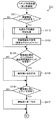
図12は、図9のステップS2における始動口スイッチ処理の詳細フローチャートの一例である。以下に、図9のステップS2における始動口スイッチ処理について、図12を参照して説明する。
[Start-up switch processing]
FIG. 12 is an example of a detailed flowchart of the start port switch process in step S2 of FIG. Hereinafter, the start port switch process in step S2 of FIG. 9 will be described with reference to FIG.

まず、ステップS201において、メイン制御部100のCPU101は、第1始動口スイッチ111aからの出力信号に基づいて、第1始動口21に遊技球が入賞したか否かを判定する。ステップS201での判定がYESの場合、処理はステップS202に移り、この判定がNOの場合、処理はステップS207に移る。   First, in step S201, the CPU 101 of the main control unit 100 determines whether or not a game ball has won a prize at the first start port 21 based on an output signal from the first start port switch 111a. If the determination in step S201 is YES, the process proceeds to step S202. If the determination is NO, the process proceeds to step S207.

ステップS202において、CPU101は、ROM102から第1特別図柄抽選の保留数の上限値Umax1(第1の実施形態では「4」)を読み出し、RAM103に記憶されている第1特別図柄抽選の保留数U1が上限値Umax1未満であるか否かを判定する。ステップS202での判定がYESの場合、処理はステップS203に移り、この判定がNOの場合、処理はステップS207に移る。   In step S 202, the CPU 101 reads the upper limit value Umax 1 (“4” in the first embodiment) of the number of first special symbol lotteries held from the ROM 102, and the number of first special symbol lottery held U 1 stored in the RAM 103. Is less than the upper limit value Umax1. If the determination in step S202 is YES, the process proceeds to step S203, and if this determination is NO, the process proceeds to step S207.

ステップS203において、CPU101は、RAM103に記憶されている保留数U1の値を、1加算した値に更新する。また、CPU101は、第1始動口21に遊技球が入賞したことを演出制御部400に対して通知するための入賞コマンドをRAM103にセットする。この入賞コマンドは、図9のステップS9の出力処理によって演出制御部400へ送信される。その後、処理はステップS204に移る。   In step S <b> 203, the CPU 101 updates the value of the holding number U <b> 1 stored in the RAM 103 to a value obtained by adding one. Further, the CPU 101 sets a winning command in the RAM 103 for notifying the effect control unit 400 that a game ball has won the first starting port 21. This winning command is transmitted to the effect control unit 400 by the output process in step S9 of FIG. Thereafter, the process proceeds to step S204.

ステップS204において、CPU101は、第1特別図柄抽選等に使用される乱数のセット(大当り乱数、図柄乱数、リーチ乱数、及び変動パターン乱数)を取得する。その後、処理はステップS205に移る。   In step S204, the CPU 101 obtains a set of random numbers (big hit random number, symbol random number, reach random number, and variation pattern random number) used for the first special symbol lottery or the like. Thereafter, the process proceeds to step S205.

ステップS205において、CPU101は、事前判定処理を行い、ステップS204で取得した乱数の各セット(遊技情報)を時系列順でRAM103に格納する。具体的には、CPU101は、直近のステップS204の処理で取得された大当り乱数等の乱数セットの大当り乱数等がROM102に記憶されている所定値等と一致するか否かに基づいて、この大当り乱数を用いる第1特別図柄抽選の結果が大当りであるか否かや、リーチ演出を実行するか否か等を事前判定する。つまり、先読み予告演出や保留変化予告演出を実行するために必要な判定を、後述する図13のステップS407及びS408の処理に先立って事前判定する。その後、事前判定に用いた乱数の各セットを時系列順でRAM103に格納する。なお、後述する図13のステップS409の処理によって第1特別図柄抽選の保留数U1の値が1減算される度に、RAM103に格納された上記乱数セットは、格納時期が早いものから順に1セットずつ削除される。このことから、例えば第1特別図柄抽選の保留数U1の値が「3」の場合、直近3回のステップS204の処理によって取得された直近3回の上記乱数セットが、時系列順でRAM103に格納されていることとなる。その後、処理はステップS206に移る。   In step S205, the CPU 101 performs pre-determination processing, and stores each set of random numbers (game information) acquired in step S204 in the RAM 103 in chronological order. Specifically, the CPU 101 determines whether or not the jackpot random number of the random number set such as the jackpot random number acquired in the processing of the latest step S204 matches a predetermined value or the like stored in the ROM 102. It is determined in advance whether or not the result of the first special symbol lottery using random numbers is a big hit, whether or not a reach effect is executed, and the like. That is, the determination necessary for executing the pre-reading notice effect and the hold change notice effect is made in advance prior to the processing of steps S407 and S408 in FIG. Thereafter, each set of random numbers used for prior determination is stored in the RAM 103 in time series order. Each time the value of the holding number U1 of the first special symbol lottery is subtracted by 1 in the process of step S409 in FIG. 13 to be described later, the random number set stored in the RAM 103 is one set in order from the earliest storage time. Deleted one by one. From this, for example, when the value of the number of holdings U1 of the first special symbol lottery is “3”, the last three random number sets acquired by the process of the last three steps S204 are stored in the RAM 103 in time series order. It will be stored. Thereafter, the process proceeds to step S206.

ステップS206において、CPU101は、第1特別図柄抽選の保留数が1増加したことを通知する第1保留数増加コマンドをRAM103にセットする。ここで、この第1保留数増加コマンドには、ステップS205の処理で行われた事前判定の結果を示す情報(以下、「事前判定情報」という)が含められている。なお、この事前判定情報を含む第1保留数増加コマンドが、図9のステップS9の出力処理によって出力されることにより、第1特別図柄抽選の保留に対する抽選結果が、第1特別図柄抽選における図柄変動が開始されるよりも前にメイン制御部100から演出制御部400に通知される。その後、処理はステップS207に移る。   In step S <b> 206, the CPU 101 sets a first hold number increase command for notifying that the hold number of the first special symbol lottery has increased by 1 in the RAM 103. Here, the first pending number increase command includes information (hereinafter referred to as “preliminary determination information”) indicating the result of the preliminary determination performed in the process of step S205. In addition, the 1st reservation number increase command containing this prior determination information is output by the output process of step S9 of FIG. The main control unit 100 notifies the effect control unit 400 before the change starts. Thereafter, the process proceeds to step S207.

ステップS207において、CPU101は、第2始動口スイッチ111bからの出力信号に基づいて、第2始動口22に遊技球が入賞したか否かを判定する。ステップS207での判定がYESの場合、処理はステップS208に移り、この判定がNOの場合、処理は図9のステップS3(ゲートスイッチ処理)に移る。   In step S207, the CPU 101 determines whether or not a game ball has won the second start port 22 based on an output signal from the second start port switch 111b. If the determination in step S207 is YES, the process proceeds to step S208. If this determination is NO, the process proceeds to step S3 (gate switch process) in FIG.

ステップS208において、CPU101は、ROM102から第2特別図柄抽選の保留数の上限値Umax2(第1の実施形態では「4」)を読み出し、RAM103に記憶されている第2特別図柄抽選の保留数U2が上限値Umax2未満であるか否かを判定する。ステップS208での判定がYESの場合、処理はステップS209に移り、この判定がNOの場合、処理は図9のステップS3(ゲートスイッチ処理)に移る。   In step S 208, the CPU 101 reads the upper limit value Umax 2 (“4” in the first embodiment) of the number of second special symbol lotteries held from the ROM 102, and the number of second special symbol lottery held U 2 stored in the RAM 103. Is less than the upper limit value Umax2. If the determination in step S208 is YES, the process proceeds to step S209, and if this determination is NO, the process proceeds to step S3 (gate switch process) in FIG.

ステップS209において、CPU101は、RAM103に格納されている保留数U2の値を、1加算した値に更新する。また、CPU101は、第2始動口22に遊技球が入賞したことを演出制御部400に対して通知するための入賞コマンドをRAM103にセットする。この入賞コマンドは、図9のステップS9の出力処理によって演出制御部400へ送信される。その後、処理はステップS210に移る。   In step S209, the CPU 101 updates the value of the holding number U2 stored in the RAM 103 to a value obtained by adding 1. Further, the CPU 101 sets a winning command in the RAM 103 for notifying the effect control unit 400 that a game ball has won the second starting port 22. This winning command is transmitted to the effect control unit 400 by the output process in step S9 of FIG. Thereafter, the process proceeds to step S210.

ステップS210において、CPU101は、第2特別図柄抽選等に使用される乱数のセット(大当り乱数、図柄乱数、リーチ乱数、及び変動パターン乱数)を取得する。その後、処理はステップS211に移る。   In step S210, the CPU 101 acquires a set of random numbers (big hit random number, symbol random number, reach random number, and variation pattern random number) used for the second special symbol lottery or the like. Thereafter, the process proceeds to step S211.

ステップS211において、CPU101は、事前判定処理を行い、ステップS210で取得した乱数の各セット(遊技情報)を時系列順でRAM103に格納する。具体的には、CPU101は、直近のステップS210の処理で取得された大当り乱数等の乱数セットの大当り乱数等がROM102に記憶されている所定値等と一致するか否かに基づいて、この大当り乱数を用いる第2特別図柄抽選の結果が大当りであるか否かや、リーチ演出を実行するか否か等を事前判定する。つまり、先読み予告演出や保留変化予告演出を実行するために必要な判定を、後述する図13のステップS407及びS408の処理に先立って事前判定する。その後、事前判定に用いた乱数の各セットを時系列順でRAM103に格納する。なお、後述する図13のステップS409の処理によって第2特別図柄抽選の保留数U2の値が1減算される度に、RAM103に格納された上記乱数セットは、格納時期が早いものから順に1セットずつ削除される。このことから、例えば第2特別図柄抽選の保留数U2の値が「3」の場合、直近3回のステップS210の処理によって取得された直近3回の上記乱数セットが、時系列順でRAM103に格納されていることとなる。その後、処理はステップS212に移る。   In step S211, the CPU 101 performs pre-determination processing, and stores each set of random numbers (game information) acquired in step S210 in the RAM 103 in chronological order. Specifically, the CPU 101 determines the jackpot based on whether or not the jackpot random number of the random number set such as the jackpot random number acquired in the processing of the latest step S210 matches a predetermined value or the like stored in the ROM 102. It is determined in advance whether or not the result of the second special symbol lottery using a random number is a big hit, whether or not to execute a reach effect. That is, the determination necessary for executing the pre-reading notice effect and the hold change notice effect is made in advance prior to the processing of steps S407 and S408 in FIG. Thereafter, each set of random numbers used for prior determination is stored in the RAM 103 in time series order. Note that each time the value of the second special symbol lottery holding number U2 is decremented by 1 in the process of step S409 of FIG. 13 to be described later, the random number set stored in the RAM 103 is one set in order from the earliest storage time. Deleted one by one. For this reason, for example, when the value of the holding number U2 of the second special symbol lottery is “3”, the last three random number sets acquired by the processing of the last three steps S210 are stored in the RAM 103 in time series order. It will be stored. Thereafter, the process proceeds to step S212.

ステップS212において、CPU101は、第2特別図柄抽選の保留数が1増加したことを通知する第2保留数増加コマンドをRAM103にセットする。ここで、この第2保留数増加コマンドには、ステップS211の処理で行われた事前判定の結果を示す情報(事前判定情報)が含められている。なお、この事前判定情報を含む第2保留数増加コマンドが、図9のステップS9の出力処理によって出力されることにより、第2特別図柄抽選の保留に対する抽選結果が、第2特別図柄抽選における図柄変動が開始されるよりも前にメイン制御部100から演出制御部400に通知される。その後、処理は図9のステップS3(ゲートスイッチ処理)に移る。   In step S <b> 212, the CPU 101 sets a second hold number increase command for notifying that the hold number of the second special symbol lottery has increased by 1 in the RAM 103. Here, the second pending number increase command includes information (preliminary determination information) indicating the result of the preliminary determination performed in the process of step S211. In addition, the 2nd reservation number increase command containing this prior determination information is output by the output process of step S9 of FIG. The main control unit 100 notifies the effect control unit 400 before the change starts. Thereafter, the process proceeds to step S3 (gate switch process) in FIG.

[特別図柄処理]
図13は、図9のステップS4における特別図柄処理の詳細フローチャートの一例である。以下に、図13を参照して、図9のステップS4における特別図柄処理について説明する。
[Special symbol processing]
FIG. 13 is an example of a detailed flowchart of the special symbol process in step S4 of FIG. Below, with reference to FIG. 13, the special symbol process in step S4 of FIG. 9 is demonstrated.

まず、ステップS401において、メイン制御部100のCPU101は、RAM103に記憶されている情報(典型的にはフラグによる情報)に基づいて、遊技機1の現在の状態が大当り遊技中(大当り遊技状態)であるか否かを判定する。つまり、特別図柄抽選に当選した場合に実行される大当り遊技(特別遊技)の実行中であるか否かを判定する。ステップS401での判定がYESの場合、処理は図9のステップS5(普通図柄処理)に移り、この判定がNOの場合、処理はステップS402に移る。   First, in step S401, the CPU 101 of the main control unit 100 determines that the current state of the gaming machine 1 is a big hit game (a big hit game state) based on information stored in the RAM 103 (typically information by a flag). It is determined whether or not. That is, it is determined whether or not the big hit game (special game) that is executed when the special symbol lottery is won. If the determination in step S401 is YES, the process proceeds to step S5 (normal symbol process) in FIG. 9, and if this determination is NO, the process proceeds to step S402.

ステップS402において、CPU101は、第1特別図柄表示器4a又は第2特別図柄表示器4bによる特別図柄の変動表示期間中であるか否かを判定する。なお、ここでの特別図柄の変動表示期間は、図10を用いて説明した特別図柄停止表示中の期間(規定時間;0.5秒間)を含んだものである。ステップS402での判定がYESの場合、処理はステップS411に移り、この判定がNOの場合、処理はステップS403に移る。   In step S402, the CPU 101 determines whether or not it is during the special symbol variable display period by the first special symbol display 4a or the second special symbol display 4b. The special symbol variation display period here includes the special symbol stop display period (specified time; 0.5 seconds) described with reference to FIG. If the determination in step S402 is yes, the process proceeds to step S411. If the determination is no, the process proceeds to step S403.

ステップS403において、CPU101は、RAM103に記憶されている保留数U2が1以上であるか否か(つまり第2特別図柄抽選が保留されているか否か)を判定する。ステップS403での判定がYESの場合、処理はステップS404に移り、この判定がNOの場合、処理はステップS405に移る。   In step S403, the CPU 101 determines whether or not the holding number U2 stored in the RAM 103 is 1 or more (that is, whether or not the second special symbol lottery is held). If the determination in step S403 is YES, the process proceeds to step S404. If the determination is NO, the process proceeds to step S405.

ステップS404において、CPU101は、図12のステップS210およびステップS211によって取得されてRAM103に格納された乱数セットのうち格納時期が最も早いものを読み出す。その後、処理はステップS407に移る。   In step S404, the CPU 101 reads the random number set acquired in steps S210 and S211 in FIG. Thereafter, the process proceeds to step S407.

一方、ステップS405において、CPU101は、RAM103に記憶されている保留数U1が1以上であるか否か(つまり第1特別図柄抽選が保留されているか否か)を判定する。ステップS405での判定がYESの場合、処理はステップS406に移り、この判定がNOの場合、実行されるべき特別図柄抽選は無いとみなして、処理はステップS415に移る。   On the other hand, in step S405, the CPU 101 determines whether or not the holding number U1 stored in the RAM 103 is 1 or more (that is, whether or not the first special symbol lottery is held). If the determination in step S405 is YES, the process proceeds to step S406. If this determination is NO, the process proceeds to step S415 assuming that there is no special symbol lottery to be executed.

ステップS406において、CPU101は、RAM103に格納されている図12のステップS204およびステップS205によって取得されてRAM103に格納された乱数セットのうち格納時期が最も早いものを読み出す。その後、処理はステップS407に移る。   In step S406, the CPU 101 reads out the random number set stored in the RAM 103 in steps S204 and S205 in FIG. Thereafter, the process proceeds to step S407.

以上のステップS403〜S406の処理によって、第2特別図柄抽選が、第1特別図柄抽選よりも優先して実行されることとなる。   The second special symbol lottery is executed in preference to the first special symbol lottery by the processing of steps S403 to S406 described above.

ステップS407において、CPU101は、特別図柄抽選の結果が大当りであるかハズレであるかを判定する大当り判定処理を実行する。具体的には、ステップS404の処理に続いてステップS407の処理を実行する場合、CPU101は、このステップS404の処理でRAM103から読み出した大当り乱数が、ROM102に記憶されている大当りの当選値と一致するか否かに基づいて、第2特別図柄抽選の結果が大当りであるかハズレであるかを判定する。一方、ステップS406の処理に続いてステップS407の処理を実行する場合、CPU101は、このステップS406の処理でRAM103から読み出した大当り乱数が、ROM102に記憶されている大当りの当選値と一致するか否かに基づいて、第1特別図柄抽選の結果が大当りであるかハズレであるかを判定する。そして、CPU101は、特別図柄抽選の結果がハズレと判定した場合、特別図柄抽選にハズレたことを表すハズレ図柄を、設定情報における特別図柄の停止図柄としてRAM103にセットする。一方、CPU101は、特別図柄抽選の結果が大当りであると判定した場合、この判定に使用した大当り乱数と共にRAM103から読み出された図柄乱数がROM102に記憶されている所定値の何れと一致するかに基づいて、今回の大当りの種類を判定する。なお、第1の実施形態では、一例として、大当り遊技後に次回大当りするまで確変遊技状態に設定される確変大当りと、大当り遊技後に次回大当りするまで通常遊技状態に設定される通常大当りとがある。また、第1の実施形態では、第2特別図柄抽選の方が、第1特別図柄抽選よりも、遊技者の利益が比較的大きい確変大当りの当選割合が多いものとする。具体的には、第2特別図柄抽選では7割が確変大当りであり3割が通常大当りであり、一方、第1特別図柄抽選では4割が確変大当りであり6割が通常大当りである。そして、
CPU101は、大当りしたこと及び大当りの種類を表す大当り図柄の情報を、設定情報における特別図柄の停止図柄の情報としてRAM103にセットする。その後、処理はステップS408に移る。
In step S407, the CPU 101 executes a big hit determination process for determining whether the result of the special symbol lottery is a big hit or a loss. Specifically, when executing the process of step S407 following the process of step S404, the CPU 101 matches the jackpot random number read from the RAM 103 in the process of step S404 with the jackpot winning value stored in the ROM 102. Whether the result of the second special symbol lottery is a big hit or a loss is determined based on whether or not to do so. On the other hand, when executing the process of step S407 following the process of step S406, the CPU 101 determines whether or not the jackpot random number read from the RAM 103 in the process of step S406 matches the jackpot winning value stored in the ROM 102. Based on this, it is determined whether the result of the first special symbol lottery is a big hit or a loss. When the result of the special symbol lottery is determined to be lost, the CPU 101 sets a lost symbol indicating that the special symbol lottery has been lost in the RAM 103 as a special symbol stop symbol in the setting information. On the other hand, when the CPU 101 determines that the result of the special symbol lottery is a big hit, which of the predetermined values stored in the ROM 102 matches the symbol random number read from the RAM 103 together with the big hit random number used for this determination? Based on this, the type of jackpot of this time is determined. In the first embodiment, as an example, there are a probabilistic big hit that is set to a probable change game state until the next big hit after the big hit game, and a normal big hit that is set to a normal game state until the next big hit after the big hit game. In the first embodiment, it is assumed that the second special symbol lottery has a higher probability of winning the odds of having a relatively large profit for the player than the first special symbol lottery. Specifically, in the second special symbol lottery, 70% is a promising big hit and 30% is a normal big hit, while in the first special symbol lottery, 40% is a promising big hit and 60% is a normal big hit. And
The CPU 101 sets, in the RAM 103, information on the jackpot symbol representing the jackpot and the type of jackpot as information on the stop symbol of the special symbol in the setting information. Thereafter, the process proceeds to step S408.

[変動パターン選択処理]
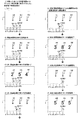
ステップS408において、CPU101は、変動パターン選択処理を実行する。具体的には、ステップS408において、CPU101は、通常遊技状態(非時短状態)のときには、図14及び図15に示す変動パターン決定テーブルHT1−1及びHT1−2を使用し、確変遊技状態(時短状態)のときには、図16及び図17に示す変動パターン決定テーブルHT2−1及びHT2−2を使用して、特別図柄抽選毎に変動パターンを決定(選択)する。ここで、この変動パターンは、表示器4に特別図柄が変動表示されてから停止表示されるまでの時間である特別図柄変動時間であり、この特別図柄変動時間は、報知演出の実行時間と同期しており報知演出の実行時間と同じ時間である。なお、以下では、変動パターン決定テーブルHT1−1、HT1−2、HT2−1およびHT2−2を、単に、HT1−1、HT1−2、HT2−1およびHT2−2いう場合がある。
[Variation pattern selection processing]
In step S408, the CPU 101 executes variation pattern selection processing. Specifically, in step S408, in the normal gaming state (non-time saving state), the CPU 101 uses the variation pattern determination tables HT1-1 and HT1-2 shown in FIGS. State), the fluctuation pattern is determined (selected) for each special symbol lottery using the fluctuation pattern determination tables HT2-1 and HT2-2 shown in FIGS. Here, this variation pattern is a special symbol variation time which is a time from when the special symbol is variably displayed on the display 4 until it is stopped and displayed, and this special symbol variation time is synchronized with the execution time of the notification effect. It is the same time as the execution time of the notification effect. Hereinafter, the variation pattern determination tables HT1-1, HT1-2, HT2-1, and HT2-2 may be simply referred to as HT1-1, HT1-2, HT2-1, and HT2-2.

まず、通常遊技状態(非時短状態)のときに、図14及び図15に示すHT1−1及びHT1−2を使用して変動パターンを選択する場合について、説明する。図14は、通常遊技状態(非時短状態)においてステップS407の処理で第1特別図柄抽選が実行された場合に、変動パターン決定に使用されるテーブルである。図15は、通常遊技状態(非時短状態)においてステップS407の処理で第2特別図柄抽選が実行された場合に、変動パターン決定に使用されるテーブルである。   First, a case where a variation pattern is selected using HT1-1 and HT1-2 shown in FIGS. 14 and 15 in the normal gaming state (non-time-short state) will be described. FIG. 14 is a table used for determining a variation pattern when the first special symbol lottery is executed in the process of step S407 in the normal gaming state (non-time saving state). FIG. 15 is a table used for determining the variation pattern when the second special symbol lottery is executed in the process of step S407 in the normal gaming state (non-time saving state).

[非時短状態/第1特別図柄抽選での変動パターン選択処理]
以下に、図14を用いて、通常遊技状態(非時短状態)においてステップS407の処理で第1特別図柄抽選が実行された場合における変動パターンの決定について、説明する。
[Non-time-short state / variation pattern selection process in the first special symbol lottery]
Hereinafter, the determination of the variation pattern when the first special symbol lottery is executed in the process of step S407 in the normal gaming state (non-time-short state) will be described with reference to FIG.

ステップS408において、CPU101は、ステップS407の大当り判定処理で第1特別図柄抽選で大当りしたと判定した場合、変動パターン乱数に基づいて変動パターン(特別図柄変動時間)を決定する。具体的には、CPU101は、ステップS407の大当り判定処理で使用した大当り乱数と共にRAM103から読み出された変動パターン乱数(0〜299のうちの何れか1つ)が、HT1−1の「大当り」の部分の各変動パターンに割り振られた乱数値の何れと一致するかに基づいて、変動パターン(特別図柄変動時間)を決定する。例えば、CPU101は、ステップS407の大当り判定処理で使用した大当り乱数と共にRAM103から読み出された変動パターン乱数が「78」である場合、HT1−1の「大当り」の部分の変動パターン「90.03秒」に割り振られた乱数値「75〜124」に含まれるので、変動パターンとして「90.03秒」を決定する。ここで、HT1−1に示すように、「大当り」の部分の変動パターン「15.01秒」、「40.01秒」、「40.02秒」、「40.03秒」、「90.01秒」、「90.02秒」、「90.03秒」、「90.04秒」及び「90.05秒」は、それぞれ、報知演出の演出パターンのタイプ「リーチ当り」、「第3SP当り」、「第2SP当り」、「第1SP当り」、「第5SPSP当り」、「第4SPSP当り」、「第3SPSP当り」、「第2SPSP当り」及び「第1SPSP当り」に対応する。また、「リーチ当り」はリーチ成立した後に大当りするタイプであり、「第1SP当り」〜「第3SP当り」は最終的にSPリーチに発展した後に大当りするタイプであり、「第1SPSP当り」〜「第5SPSP当り」は最終的にSPSPリーチに発展した後に大当りするタイプである。   In step S408, if the CPU 101 determines in the jackpot determination process of step S407 that the first special symbol lottery has been won, the CPU 101 determines a variation pattern (special symbol variation time) based on the variation pattern random number. Specifically, the CPU 101 determines that the variation pattern random number (any one of 0 to 299) read from the RAM 103 together with the big hit random number used in the big hit determination process in step S407 is the “big hit” of HT1-1. The variation pattern (special symbol variation time) is determined based on which of the random number values assigned to each variation pattern of the portion of (). For example, when the variation pattern random number read from the RAM 103 together with the big hit random number used in the big hit determination process in step S407 is “78”, the CPU 101 sets the fluctuation pattern “90.03” of the “big hit” portion of HT1-1. Since it is included in the random number values “75 to 124” assigned to “second”, “90.03 seconds” is determined as the variation pattern. Here, as indicated by HT1-1, the fluctuation pattern “15.01 seconds”, “40.01 seconds”, “40.02 seconds”, “40.03 seconds”, “90. “01 seconds”, “90.02 seconds”, “90.03 seconds”, “90.04 seconds”, and “90.05 seconds” indicate the types of effect patterns of the notification effect “per reach” and “third SP”, respectively. "Per hit", "per second SP", "per first SP", "per fifth SPSP", "per fourth SPSP", "per third SPSP", "per second SPSP", and "per first SPSP". In addition, “per reach” is a type that hits big after reaching reach, “per first SP” to “per third SP” is a type that hits big after finally developing to SP reach, “per first SPSP” The “per 5th SPSP” is a type that hits big after finally developing to SPSP reach.

なお、リーチ(リーチ演出)とは、報知演出において例えば複数の装飾図柄のうち最後に停止される変動中の装飾図柄が、特定の図柄で停止表示された場合には、既に停止中の他の図柄と合わせて大当りの図柄パターンとなることを期待させる演出であり、典型的には、右側と左側の装飾図柄が同じ図柄(例えば7)で停止しており、最後に停止される中央の装飾図柄が、同じ図柄(例えば7)で停止する(つまり、ゾロ目777となる)ことを期待させて変動表示される演出である。また、SPリーチとは、一般にスーパーリーチやスペシャルリーチと呼ばれ、リーチよりも大当りすることを更に期待させる演出であり、例えば主人公のキャラクタがミニゲームを行う動画像の演出である。また、SPSPリーチとは、一般にスーパースーパーリーチやスペシャルスペシャルリーチと呼ばれ、SPリーチ演出よりも大当りすることを更に期待させる演出であり、例えば主人公のキャラクタが敵のキャラクタと戦う動画像の演出である。   Note that the reach (reach effect) is, for example, when a changing decorative symbol that is stopped last among a plurality of decorative symbols in a notification effect is stopped and displayed with a specific symbol. It is an effect that expects to be a big hit symbol pattern together with the symbol. Typically, the right and left decorative symbols are stopped at the same symbol (for example, 7), and the central ornament that stops at the end This is an effect that is variably displayed in the expectation that the symbol stops at the same symbol (for example, 7) (that is, it becomes a doublet 777). The SP reach is generally referred to as super reach or special reach, and is an effect that further expects to win more than reach, for example, an effect of a moving image in which a hero character plays a mini game. In addition, SPSP reach is generally called super super reach or special special reach, and is an effect that further expects a big hit than SP reach production. For example, it is a production of a moving image in which a hero character fights against an enemy character. is there.

また、ステップS408において、CPU101は、ステップS407の大当り判定処理で第1特別図柄抽選でハズレと判定した場合、第1特別図柄抽選の保留数(U1)、リーチ乱数、及び変動パターン乱数に基づいて変動パターン(特別図柄変動時間)を決定する。   In step S408, when the CPU 101 determines that the first special symbol lottery is lost in the big hit determination process in step S407, the CPU 101 determines based on the hold number (U1) of the first special symbol lottery, the reach random number, and the fluctuation pattern random number. The variation pattern (special symbol variation time) is determined.

具体的には、CPU101は、第1特別図柄抽選の保留数が「1」又は「2」である場合、ステップS407の大当り判定処理で使用した大当り乱数と共にRAM103から読み出されたリーチ乱数(0〜99のうちの何れか1つ)が、HT1−1の「ハズレ」の保留数「1、2」の部分のリーチ乱数値範囲「0〜69」に含まれるのかリーチ乱数値範囲「70〜99」に含まれるのかを判定する。   Specifically, the CPU 101 determines the reach random number (0) read from the RAM 103 together with the jackpot random number used in the jackpot determination process in step S407 when the number of the first special symbol lottery is “1” or “2”. Or any one of 99 to 99) is included in the reach random number value range “0 to 69” of the retained number “1, 2” of the “losing” of HT1-1. 99 ”is determined.

そして、CPU101は、この読み出されたリーチ乱数がリーチ乱数値範囲「0〜69」に含まれる場合、ステップS407の大当り判定処理で使用した大当り乱数と共にRAM103から読み出された変動パターン乱数(0〜299のうちの何れか1つ)が、変動パターン乱数値範囲「0〜59」に含まれるのか変動パターン乱数値範囲「60〜299」に含まれるのかを判定する。そして、CPU101は、この変動パターン乱数が変動パターン乱数値範囲「0〜59」に含まれる場合には変動パターンとして「8.00秒」を決定し、この変動パターン乱数が変動パターン乱数値範囲「60〜299」に含まれる場合には変動パターンとして「13.50秒」を決定する。ここで、HT1−1に示すように、変動パターン「8.00秒」及び「13.50秒」は、何れも、報知演出の演出パターンのタイプ「即ハズレ」に対応する。なお、「即ハズレ」は、リーチ成立もなく即ハズレる演出パターンのタイプである。   Then, when the read reach random number is included in the reach random number value range “0 to 69”, the CPU 101 reads the fluctuation pattern random number (0) read from the RAM 103 together with the big hit random number used in the big hit determination process in step S407. ˜299) is included in the fluctuation pattern random value range “0-59” or in the fluctuation pattern random value range “60-299”. Then, when the fluctuation pattern random number is included in the fluctuation pattern random value range “0 to 59”, the CPU 101 determines “8.00 seconds” as the fluctuation pattern, and the fluctuation pattern random number is changed to the fluctuation pattern random value range “ In the case of “60 to 299”, “13.50 seconds” is determined as the variation pattern. Here, as indicated by HT1-1, the variation patterns “8.00 seconds” and “13.50 seconds” both correspond to the effect pattern type “immediately lost”. “Immediately lost” is a type of production pattern that immediately loses without reaching reach.

一方、CPU101は、この読み出されたリーチ乱数がリーチ乱数値範囲「70〜99」に含まれる場合、ステップS407の大当り判定処理で使用した大当り乱数と共にRAM103から読み出された変動パターン乱数(0〜299のうちの何れか1つ)が、HT1−1の上記したリーチ乱数値範囲「70〜99」の部分の各変動パターンに割り振られた変動パターン乱数値範囲の何れに含まれるかに基づいて、変動パターン(特別図柄変動時間)を決定する。例えば、CPU101は、ステップS407の大当り判定処理で使用した大当り乱数と共にRAM103から読み出された変動パターン乱数が「260」である場合、変動パターン「40.05秒」に割り振られた変動パターン乱数値範囲「256〜271」に含まれるので、変動パターンとして「40.05秒」を決定する。ここで、HT1−1に示すように、HT1−1の上記したリーチ乱数値範囲「70〜99」の部分の変動パターン「15.02秒」、「40.04秒」、「40.05秒」、「40.06秒」、「90.06秒」、「90.07秒」、「90.08秒」、「90.09秒」及び「90.10秒」は、それぞれ、報知演出の演出パターンのタイプ「リーチハズレ」、「第3SPハズレ」、「第2SPハズレ」、「第1SPハズレ」、「第5SPSPハズレ」、「第4SPSPハズレ」、「第3SPSPハズレ」、「第2SPSPハズレ」及び「第1SPSPハズレ」に対応する。また、「リーチハズレ」はリーチ成立した後にハズレるタイプであり、「第1SPハズレ」〜「第3SPハズレ」は最終的にSPリーチに発展した後にハズレるタイプであり、「第1SPSPハズレ」〜「第5SPSPハズレ」は最終的にSPSPリーチに発展した後にハズレるタイプである。   On the other hand, when the read reach random number is included in the reach random number value range “70 to 99”, the CPU 101 reads the variation pattern random number (0) read from the RAM 103 together with the big hit random number used in the big hit determination process in step S407. ˜299) is included in the variation pattern random value range assigned to each variation pattern in the above reach random value range “70 to 99” of HT1-1. Then, the variation pattern (special symbol variation time) is determined. For example, when the variation pattern random number read from the RAM 103 together with the jackpot random number used in the jackpot determination process in step S407 is “260”, the CPU 101 determines the variation pattern random value assigned to the variation pattern “40.05 seconds”. Since it is included in the range “256 to 271”, “40.05 seconds” is determined as the variation pattern. Here, as indicated by HT1-1, the fluctuation patterns “15.02 seconds”, “40.04 seconds”, “40.05 seconds” of the above-described reach random number value range “70 to 99” of HT1-1. ”,“ 40.06 seconds ”,“ 90.06 seconds ”,“ 90.07 seconds ”,“ 90.08 seconds ”,“ 90.09 seconds ”, and“ 90.10 seconds ” Production pattern types “Leach Loss”, “3rd SP Loss”, “2nd SP Loss”, “1st SP Loss”, “5th SPSP Loss”, “4th SPSP Loss”, “3rd SPSP Loss”, “2nd SPSP Loss” and This corresponds to “first SPSP loss”. Further, “Leach Loss” is a type that loses after the reach is established, and “First SP Loss” to “3rd SP Loss” are types that finally lose after being developed into SP Reach, and “First SPSP Loss” to “ “Fifth SPSP Loss” is a type that loses after finally developing into SPSP reach.

また、CPU101は、第1特別図柄抽選の保留数が「3」の場合、上記した第1特別図柄抽選の保留数が「1」又は「2」の場合と基本的に同様にして、変動パターンを決定する。但し、第1特別図柄抽選の保留数が「3」の場合には、CPU101は、HT1−1に示すように、上記した第1特別図柄抽選の保留数が「1」又は「2」の場合に対して、リーチ乱数値範囲「0〜69」を「0〜79」に置き換え、リーチ乱数値範囲「70〜99」を「80〜99」に置き換え、又、変動パターン「8.00秒」に割り振られた変動パターン乱数値範囲「0〜59」を「0〜209」に置き換え、変動パターン「13.50秒」に割り振られた変動パターン乱数値範囲「60〜299」を「210〜299」に置き換えた乱数値範囲によって、変動パターンを決定する。   In addition, when the number of the first special symbol lottery is “3”, the CPU 101 basically performs the variation pattern in the same manner as when the number of the first special symbol lottery is “1” or “2”. To decide. However, when the number of holdings of the first special symbol lottery is “3”, as shown in HT1-1, the CPU 101 has the number of holdings of the first special symbol lottery being “1” or “2”. On the other hand, the reach random value range “0-69” is replaced with “0-79”, the reach random value range “70-99” is replaced with “80-99”, and the fluctuation pattern “8.00 seconds”. The variable pattern random value range “0 to 59” assigned to “0” to “209” is replaced with “0 to 209”, and the fluctuation pattern random value range “60 to 299” assigned to the fluctuation pattern “13.50 seconds” is changed to “210 to 299”. The variation pattern is determined by the random value range replaced with “”.

また、CPU101は、第1特別図柄抽選の保留数が「4」の場合、上記した第1特別図柄抽選の保留数が「1」又は「2」の場合と基本的に同様にして、変動パターンを決定する。但し、第1特別図柄抽選の保留数が「4」の場合には、CPU101は、HT1−1に示すように、上記した第1特別図柄抽選の保留数が「1」又は「2」の場合に対して、リーチ乱数値範囲「0〜69」を「0〜84」に置き換え、リーチ乱数値範囲「70〜99」を「85〜99」に置き換え、又、変動パターン「8.00秒」に割り振られた変動パターン乱数値範囲「0〜59」を「210〜269」に置き換え、変動パターン「13.50秒」に割り振られた変動パターン乱数値範囲「60〜299」を「270〜299」に置き換え、更に、演出パターンのタイプ「即ハズレ」に対応し変動パターン乱数値範囲「0〜209」が割り振られた変動パターン「3.00秒」が加えられた内容の乱数値範囲によって、変動パターンを決定する。   In addition, when the number of holds for the first special symbol lottery is “4”, the CPU 101 basically performs the variation pattern similarly to the case where the number of holds for the first special symbol lottery is “1” or “2”. To decide. However, when the number of the first special symbol lottery is “4”, the CPU 101, as shown in HT1-1, when the number of the first special symbol lottery is “1” or “2”. On the other hand, the reach random value range “0-69” is replaced with “0-84”, the reach random value range “70-99” is replaced with “85-99”, and the fluctuation pattern “8.00 seconds” The variable pattern random value range “0 to 59” allocated to the variable pattern is replaced with “210 to 269”, and the random pattern value range “60 to 299” allocated to the variable pattern “13.50 seconds” is converted to “270 to 299”. In addition, according to the random value range of the content to which the variation pattern “3.00 seconds” to which the variation pattern random value range “0 to 209” is assigned in correspondence with the production pattern type “immediately lost” is added, Deciding the fluctuation pattern To.

以上に図14に示す変動パターン決定テーブルHT1−1を用いて説明したように、通常遊技状態(非時短状態)において第1特別図柄抽選でハズレた場合には、第1特別図柄抽選の保留数が少ないほど、リーチありの変動パターンが選択され易く、又、リーチなしの変動パターンが選択された場合には第1特別図柄抽選の保留数が少ないほど長い変動パターンが選択され易い。   As described above with reference to the variation pattern determination table HT1-1 shown in FIG. 14, when the first special symbol lottery is lost in the normal gaming state (non-time-short state), the number of first special symbol lottery holds The smaller the variation is, the easier it is to select the variation pattern with reach, and when the variation pattern without reach is selected, the smaller the number of the first special symbol lottery is, the easier the variation pattern is selected.

[大当り信頼度]
ここで、大当り信頼度(大当り期待度)について説明する。大当り信頼度が高い演出とは、その演出が実行された場合において大当りが報知される可能性が高い演出であり、大当り信頼度が低い演出とは、その演出が実行された場合において大当りが報知される可能性が低い演出である。以下、図15に示すHT1−1を用いて具体的に説明する。HT1−1の「大当り」の部分から分かるように、大当りの場合には、「リーチ当り」、「第3SP当り」、「第2SP当り」、「第1SP当り」、「第5SPSP当り」、「第4SPSP当り」、「第3SPSP当り」、「第2SPSP当り」、「第1SPSP当り」の順で、変動パターン乱数値範囲が大きくなっている(一部同一あり)。一方で、HT1−1の「ハズレ」の部分から分かるように、ハズレの場合には、「リーチハズレ」、「第3SPハズレ」、「第2SPハズレ」、「第1SPハズレ」、「第5SPSPハズレ」、「第4SPSPハズレ」、「第3SPSPハズレ」、「第2SPSPハズレ」、「第1SPSPハズレ」の順で、変動パターン乱数値範囲が小さくなっている(一部同一あり)。以上から分かるように、大当りの場合に実行され易くハズレの場合に実行され難い演出は大当り信頼度が高い一方で、大当りの場合に実行され難くハズレの場合に実行され易い演出は大当り信頼度が低い。つまり、「リーチ演出」、「第3SPリーチ演出」、「第2SPリーチ演出」、「第1SPリーチ演出」、「第5SPSPリーチ演出」、「第4SPSPリーチ演出」、「第3SPSPリーチ演出」、「第2SPSPリーチ演出」、「第1SPSPリーチ演出」の順で大当り信頼度が高くなる。
[Big hit reliability]
Here, the jackpot reliability (expectation for jackpot) will be described. An effect with a high jackpot reliability is an effect that is highly likely to be notified of a big hit when the effect is executed, and an effect with a low jackpot reliability is a notification of a big hit when the effect is executed. It is a production that is unlikely to be performed. Hereinafter, it demonstrates concretely using HT1-1 shown in FIG. As can be seen from the “big hit” portion of HT1-1, in the case of big hit, “per reach”, “per third SP”, “per second SP”, “per first SP”, “per fifth SPSP”, “ The variation pattern random value range increases in the order of “per fourth SPSP”, “per third SPSP”, “per second SPSP”, and “per first SPSP” (partially the same). On the other hand, as can be seen from the “losing” portion of HT1-1, in the case of losing, “reach losing”, “third SP losing”, “second SP losing”, “first SP losing”, “fifth SPSP losing”. , The variation pattern random value range becomes smaller in the order of “fourth SPSP loss”, “third SPSP loss”, “second SPSP loss”, “first SPSP loss” (partially the same). As can be seen from the above, the performance that is easy to execute in the case of a big hit and difficult to execute in the case of a loss is high in the reliability of the big hit, while the effect that is difficult to execute in the case of big hit and is easy to be executed in the case of a loss has a big hit reliability Low. That is, “reach effect”, “third SP reach effect”, “second SP reach effect”, “first SP reach effect”, “fifth SPSP reach effect”, “fourth SPSP reach effect”, “third SPSP reach effect”, “ The jackpot reliability increases in the order of “second SPSP reach production” and “first SPSP reach production”.

[非時短状態/第2特別図柄抽選での変動パターン選択処理]
以下に、図15を用いて、通常遊技状態(非時短状態)においてステップS407の処理で第2特別図柄抽選が実行された場合における変動パターンの決定について、説明する。ステップS408において、CPU101は、図14を用いて説明した変動パターン決定の処理と基本的に同様の処理を行って、変動パターンを決定する。但し、CPU101は、図14を用いて説明した変動パターン決定の処理ではHT1−1を用いて第1特別図柄抽選に対して処理を行ったのに対して、この変動パターン決定の処理では図15に示すHT1−2を用いて第2特別図柄抽選に対して処理を行う点で異なる。ここで、図15に示すHT1−2は、図14に示したHT1−1に対して、「第1特別図柄抽選の保留数」が「第2特別図柄抽選の保留数」に置き換わった点で異なるのみである。つまり、図14を用いて説明した変動パターン決定の処理では第1特別図柄抽選の保留数が考慮されたのに対して、この変動パターン決定の処理では第2特別図柄抽選の保留数が考慮される。
[Non-time-short state / variation pattern selection process in the second special symbol lottery]
The determination of the variation pattern when the second special symbol lottery is executed in the process of step S407 in the normal gaming state (non-short-time state) will be described below with reference to FIG. In step S408, the CPU 101 determines a variation pattern by performing basically the same processing as the variation pattern determination processing described with reference to FIG. However, the CPU 101 performs processing for the first special symbol lottery using HT1-1 in the variation pattern determination processing described with reference to FIG. 14, whereas in the variation pattern determination processing illustrated in FIG. It is different in that processing is performed on the second special symbol lottery using HT1-2 shown in FIG. Here, HT1-2 shown in FIG. 15 is different from HT1-1 shown in FIG. 14 in that “the number of holdings of the first special symbol lottery” is replaced with “the number of holdings of the second special symbol lottery”. Only different. In other words, while the variation pattern determination process described with reference to FIG. 14 takes into account the number of first special symbol lottery holds, the variation pattern determination process takes into account the number of second special symbol lottery holds. The

[時短状態/第1特別図柄抽選での変動パターン選択処理]
以下に、図16を用いて、確変遊技状態(時短状態)においてステップS407の処理で第1特別図柄抽選が実行された場合における変動パターンの決定について、説明する。ステップS408において、CPU101は、図14を用いて説明した変動パターン決定の処理と基本的に同様の処理を行って、変動パターンを決定する。但し、CPU101は、図14を用いて説明した変動パターン決定の処理ではHT1−1を用いて第1特別図柄抽選に対して処理を行ったのに対して、この変動パターン決定の処理では図16に示すHT2−1を用いて第1特別図柄抽選に対して処理を行う点で異なる。ここで、図16に示すHT2−1は、図14に示したHT1−1に対して、「ハズレ」においてリーチ乱数によってリーチなしが選択された場合において、第1特別図柄抽選の保留数に関わらず一律に変動パターン「13.50秒」(即ハズレに対応)が選択される点で異なる。
[Time-short state / variation pattern selection process in the first special symbol lottery]
The determination of the variation pattern when the first special symbol lottery is executed in the process of step S407 in the probability variation gaming state (short time state) will be described below with reference to FIG. In step S408, the CPU 101 determines a variation pattern by performing basically the same processing as the variation pattern determination processing described with reference to FIG. However, the CPU 101 performs processing for the first special symbol lottery using the HT1-1 in the variation pattern determination processing described with reference to FIG. 14, whereas in the variation pattern determination processing illustrated in FIG. It differs by the point which processes with respect to a 1st special symbol lottery using HT2-1 shown. Here, HT2-1 shown in FIG. 16 is different from HT1-1 shown in FIG. 14 in relation to the number of holdings of the first special symbol lottery when “no reach” is selected by “reach random number” in “losing”. The difference is that the variation pattern “13.50 seconds” (corresponding to immediate loss) is selected.

[時短状態/第2特別図柄抽選での変動パターン選択処理]
以下に、図17を用いて、確変遊技状態(時短状態)においてステップS407の処理で第2特別図柄抽選が実行された場合における変動パターンの決定について、説明する。ステップS408において、CPU101は、図14を用いて説明した変動パターン決定の処理と基本的に同様の処理を行って、変動パターンを決定する。但し、CPU101は、図14を用いて説明した変動パターン決定の処理ではHT1−1を用いて第1特別図柄抽選に対して処理を行ったのに対して、この変動パターン決定の処理では図17に示すHT2−2を用いて第2特別図柄抽選に対して処理を行う点で異なる。ここで、図17に示すように、HT2−2は、図14に示したHT1−1に対して、「第1特別図柄抽選の保留数」が「第2特別図柄抽選の保留数」に置き換わっている。つまり、図14を用いて説明した変動パターン決定の処理では第1特別図柄抽選の保留数が考慮されたのに対して、この変動パターン決定の処理では第2特別図柄抽選の保留数が考慮される。また、図17に示すように、HT2−2では、「ハズレ」における第2特別図柄抽選の保留数「1」の場合においてリーチ乱数によってリーチなしが選択された場合に、一律に変動パターン「13.50秒」が決定される。また、図17に示すように、HT2−2では、「ハズレ」における第2特別図柄抽選の保留数「2〜4」の場合においてリーチ乱数によってリーチなしが選択された場合に、変動パターン乱数値範囲「0〜239」において変動パターン「2.00秒」が決定され、変動パターン乱数値範囲「240〜269」において変動パターン「4.00秒」が決定され、変動パターン乱数値範囲「270〜299」において変動パターン「10.00秒」が決定される。
[Time-short state / variation pattern selection process in the second special symbol lottery]
Hereinafter, the determination of the variation pattern when the second special symbol lottery is executed in the process of step S407 in the probability variation gaming state (short time state) will be described with reference to FIG. In step S408, the CPU 101 determines a variation pattern by performing basically the same processing as the variation pattern determination processing described with reference to FIG. However, the CPU 101 performs processing for the first special symbol lottery using HT1-1 in the variation pattern determination processing described with reference to FIG. 14, whereas in the variation pattern determination processing illustrated in FIG. It is different in that processing is performed for the second special symbol lottery using HT2-2 shown in FIG. Here, as shown in FIG. 17, HT2-2 replaces “Holding number of first special symbol lottery” with “Holding number of second special symbol lottery” with respect to HT1-1 shown in FIG. ing. In other words, while the variation pattern determination process described with reference to FIG. 14 takes into account the number of first special symbol lottery holds, the variation pattern determination process takes into account the number of second special symbol lottery holds. The Also, as shown in FIG. 17, in HT2-2, when the number of holds in the second special symbol lottery “1” in “losing” is “1” and no reach is selected by the reach random number, the variation pattern “13” is uniform. .50 seconds "is determined. Also, as shown in FIG. 17, in HT2-2, when no reach is selected by the reach random number in the case of the holding number “2-4” of the second special symbol lottery in “losing”, the fluctuation pattern random value The variation pattern “2.00 seconds” is determined in the range “0 to 239”, the variation pattern “4.00 seconds” is determined in the variation pattern random value range “240 to 269”, and the variation pattern random value range “270 to 270”. In “299”, the fluctuation pattern “10.00 seconds” is determined.

ここで、ステップS403〜S406での処理で説明したように、第1の実施形態では、第2特別図柄抽選の保留が、第1特別図柄抽選の保留よりも優先して消化される。また、確変遊技状態(時短状態)では、図9のステップS5及びS7での処理で説明したように、電動チューリップ27が頻繁に長期間開放して第2始動口22に遊技球が頻繁に入賞するので、第2特別図柄抽選が頻繁に連続して実行される。また、ステップS407での処理で説明したように、第2始動口22への遊技球入賞による第2特別図柄抽選の方が、第1始動口21への遊技球入賞による第1特別図柄抽選よりも、次回大当りするまで確変遊技状態(時短状態)に制御される確変大当り(遊技者の利益が大きい大当り)の当選割合が大きい。このことから、逆に言えば、確変遊技状態(時短状態)において、第1特別図柄抽選が実行されると、通常遊技状態に制御されることになる通常当たり(遊技者の利益が小さい大当り)に当選してしまう可能性が高くなってしまうと言える。第1の実施形態では、以上に図17のHT2−2を用いて説明したように、確変遊技状態(時短状態)においては、第2特別図柄抽選の保留数が2〜4でリーチなしの場合には短時間の変動パターン(2.00秒、4.00秒)を選択し易くして第2特別図柄抽選の保留が高速で消化されるようにしてスピード感のある遊技を実行する一方で、第2特別図柄抽選の保留数が1でリーチなしの場合には長時間の変動パターン(13.50秒)を必ず選択して遊技者に比較的不利な第1特別図柄抽選が実行され難く制御している。更に、第1の実施形態では、以上に図17のHT2−1を用いて説明したように、確変遊技状態(時短状態)においては、遊技者に比較的不利な第1特別図柄抽選が実行されたとしても、第1特別図柄抽選の保留数が1〜4の全てにおいて、リーチなしの場合には長時間の変動パターン(13.50秒)を必ず選択して、第2始動口22に遊技球が入賞して遊技者に比較的有利な第2特別図柄抽選が実行されるための時間を稼ぐように制御している。   Here, as described in the processing in steps S403 to S406, in the first embodiment, the second special symbol lottery hold is digested in preference to the first special symbol lottery hold. Further, in the probability variation gaming state (short time state), as described in the processing in steps S5 and S7 in FIG. 9, the electric tulip 27 is frequently opened for a long period of time, and the game balls are frequently won at the second starting port 22. Therefore, the second special symbol lottery is executed frequently and continuously. Further, as described in the processing in step S407, the second special symbol lottery by winning the game ball to the second starting port 22 is more than the first special symbol lottery by winning the game ball to the first starting port 21. However, the winning ratio of probability variation big hits (big hits where the player's profit is large), which is controlled to the probability variation gaming state (short time state) until the next big hit, is large. Therefore, conversely, in the probability variation gaming state (short time state), when the first special symbol lottery is executed, it is controlled to the normal gaming state (a big hit with a small profit for the player) It can be said that there is a high possibility of winning. In the first embodiment, as described above with reference to HT2-2 in FIG. 17, in the probability variation gaming state (short-time state), the number of the second special symbol lottery hold is 2 to 4 and there is no reach On the other hand, it is easy to select a short-time variation pattern (2.00 seconds, 4.00 seconds), and the second special symbol lottery hold is digested at high speed while executing a game with a sense of speed. When the number of the second special symbol lottery is 1 and there is no reach, it is difficult to execute the first special symbol lottery which is relatively disadvantageous to the player by always selecting a long time fluctuation pattern (13.50 seconds). I have control. Furthermore, in the first embodiment, as described above with reference to HT2-1 in FIG. 17, in the probability variation gaming state (time-short state), the first special symbol lottery that is relatively disadvantageous to the player is executed. Even if the number of the first special symbol lottery is 1 to 4, the long-term fluctuation pattern (13.50 seconds) must be selected in the absence of reach, and the game will be played at the second start port 22 Control is performed so as to earn time for the ball to win and the second special symbol lottery that is relatively advantageous to the player to be executed.

以上のようにしてステップS408において決定された変動パターンの情報(つまり、報知演出の実行時間:報知演出の演出パターンのタイプの情報とも言える)は、設定情報としてRAM103にセットされる。その後、処理はステップS409に移る。   Information on the variation pattern determined in step S408 as described above (that is, it can be said that the execution time of the notification effect: the information about the type of the effect pattern of the notification effect) is set in the RAM 103 as setting information. Thereafter, the process proceeds to step S409.

ステップS409において、CPU101は、ステップS407の大当り判定処理によってセットされた設定情報、及びステップS408の変動パターン選択処理によってセットされた設定情報を含む報知演出開始コマンドを生成して、RAM103にセットする。ここで、報知演出開始コマンドは、演出制御部400に対して、画像表示部6及びスピーカ35等による報知演出の開始を指示するコマンドである。また、報知演出開始コマンドに含まれる設定情報には、第1特別図柄抽選及び第2特別図柄抽選の何れが実行されたかを示す情報も含まれる。また、CPU101は、現在の遊技状態(例えば、確変遊技状態)を示す遊技状態通知コマンドをRAM103にセットする。また、その際、ステップS404の処理に続いてステップS407、ステップS408の処理を実行した場合には、CPU101は、RAM103に記憶されている保留数U2を1減算した値に更新するとともに、ステップS404で読み出した乱数セットをRAM103から削除する。一方、ステップS406の処理に続いてステップS407、ステップS408の処理を実行した場合には、CPU101は、RAM103に記憶されている保留数U1を1減算した値に更新するとともに、ステップS406で読み出した乱数セットをRAM103から削除する。また、上記した報知演出開始コマンドおよび遊技状態通知コマンドは、図9のステップS9における出力処理によって、演出制御部400へ送信される。その後、処理はステップS410に移る。   In step S409, the CPU 101 generates a notification effect start command including the setting information set by the jackpot determination process in step S407 and the setting information set by the variation pattern selection process in step S408, and sets the notification effect start command in the RAM 103. Here, the notification effect start command is a command for instructing the effect control unit 400 to start the notification effect by the image display unit 6, the speaker 35, and the like. The setting information included in the notification effect start command includes information indicating which of the first special symbol lottery and the second special symbol lottery has been executed. Further, the CPU 101 sets a gaming state notification command indicating the current gaming state (for example, a probable variation gaming state) in the RAM 103. At that time, when the processing of step S407 and step S408 is executed following the processing of step S404, the CPU 101 updates the number of holdings U2 stored in the RAM 103 to a value obtained by subtracting 1 and also executes step S404. The random number set read out in (1) is deleted from the RAM 103. On the other hand, when the processing of step S407 and step S408 is executed subsequent to the processing of step S406, the CPU 101 updates the holding number U1 stored in the RAM 103 to a value obtained by subtracting 1 and reads it in step S406. The random number set is deleted from the RAM 103. Further, the notification effect start command and the game state notification command described above are transmitted to the effect control unit 400 by the output process in step S9 of FIG. Thereafter, the process proceeds to step S410.

ステップS410において、CPU101は、ステップS409の処理でセットされた報知演出開始コマンドに含まれている設定情報に基づいて、第1特別図柄表示器4a又は第2特別図柄表示器4bによる特別図柄の変動表示を開始する。その後、処理はステップS411に移る。   In step S410, the CPU 101 changes the special symbol by the first special symbol display 4a or the second special symbol display 4b based on the setting information included in the notification effect start command set in the process of step S409. Start displaying. Thereafter, the process proceeds to step S411.

ステップS411において、CPU101は、ステップS410における特別図柄の変動表示の開始時点から、ステップS408の変動パターン選択処理で設定された変動パターンが示す特別図柄変動時間が経過したか否かを判定する。ステップS411での判定がYESの場合、処理はステップS412に移り、この判定がNOの場合、処理は図9のステップS5(普通図柄処理)に移る。   In step S411, the CPU 101 determines whether or not the special symbol variation time indicated by the variation pattern set in the variation pattern selection process in step S408 has elapsed since the start of the special symbol variation display in step S410. If the determination in step S411 is YES, the process proceeds to step S412. If the determination is NO, the process proceeds to step S5 (ordinary symbol process) in FIG.

ステップS412において、CPU101は、画像表示部6等による報知演出の終了を指示する報知演出停止コマンドをRAM103にセットする。その後、処理はステップS413に移る。なお、ステップS412でセットされた報知演出停止コマンドは、図9のステップS9の出力処理によって演出制御部400へ送信される。   In step S <b> 412, the CPU 101 sets a notification effect stop command instructing the end of the notification effect by the image display unit 6 or the like in the RAM 103. Thereafter, the process proceeds to step S413. Note that the notification effect stop command set in step S412 is transmitted to the effect control unit 400 by the output process in step S9 of FIG.

ステップS413において、CPU101は、ステップS410の処理で開始した第1特別図柄表示器4a又は第2特別図柄表示器4bによる特別図柄の変動表示を終了し、第1特別図柄表示器4a又は第2特別図柄表示器4bに、特別図柄抽選結果を報知する図柄を停止した状態で所定時間(0.5秒間)表示させる。なお、このとき、CPU101は、図柄確定コマンドをRAM103にセットする。その後、処理はステップS414に移る。   In step S413, the CPU 101 ends the special symbol variation display by the first special symbol display 4a or the second special symbol display 4b started in the process of step S410, and the first special symbol display 4a or the second special symbol display 4b. The symbol display 4b is displayed for a predetermined time (0.5 seconds) in a state where the symbol for notifying the special symbol lottery result is stopped. At this time, the CPU 101 sets a symbol determination command in the RAM 103. Thereafter, the process proceeds to step S414.

ステップS414において、CPU101は、停止中処理を実行する。具体的には、CPU101は、ステップS407の大当り判定処理で大当りしたと判定した場合、RAM103に記憶されている情報(典型的にはフラグによる情報)を大当り遊技中(大当り遊技状態)であることを示すものに変更し、大当り遊技演出の開始を指示するオープニングコマンドをRAM103にセットする。なお、このオープニングコマンドは、ステップS413の処理で特別図柄の停止表示が開始された時点から所定時間(0.5秒間)経過時に、図9のステップS9の出力処理によって演出制御部400へ送信され、大当り遊技演出が開始される。   In step S414, the CPU 101 executes a stop process. Specifically, when the CPU 101 determines that the big hit is determined in step S407, the information stored in the RAM 103 (typically information based on a flag) is in the big hit game (the big hit game state). And an opening command for instructing the start of the big hit game effect is set in the RAM 103. This opening command is transmitted to the effect control unit 400 by the output process of step S9 in FIG. 9 when a predetermined time (0.5 seconds) has elapsed since the stop display of the special symbol was started in the process of step S413. The jackpot game production is started.

ステップS415おいて、CPU101は、客待ちコマンドおよび現在の遊技状態を示す遊技状態通知コマンドを、ステップS416の処理(後述)で既に送信済みであるか否かを判定する。ここで、客待ちコマンドとは、特別図柄の停止表示が終了した時点において、特別図柄抽選の保留が存在しない場合に送信されるコマンドであり、特別図柄抽選の抽選結果を報知する報知演出が実行されていない状態(いわゆる客待ち状態)になったことを通知するコマンドである。ステップS415での判定がYESの場合、処理は図9のステップS5(普通図柄処理)に移り、この判定がNOの場合、処理はステップS416に移る。   In step S415, the CPU 101 determines whether a customer waiting command and a gaming state notification command indicating the current gaming state have already been transmitted in the process of step S416 (described later). Here, the customer waiting command is a command that is transmitted when there is no special symbol lottery hold at the time when the special symbol stop display is completed, and a notification effect for informing the lottery result of the special symbol lottery is executed. This is a command for notifying that it has not been made (so-called customer waiting state). If the determination in step S415 is YES, the process proceeds to step S5 (ordinary symbol process) in FIG. 9, and if this determination is NO, the process proceeds to step S416.

ステップS416おいて、CPU101は、客待ちコマンドおよび遊技状態通知コマンドをRAM103にセットする。この客待ちコマンドおよび遊技状態通知コマンドは図9のステップS9の出力処理によって演出制御部400へ送信され、当該客待ちコマンドに基づいて、所定の停止演出(例えば装飾図柄停止表示の演出)が開始される。なお、上記した停止演出が開始されてから所定時間(例えば90秒)が経過すると、客待ち演出が開始される。ここで、客待ち演出は、例えば、遊技機1の題材となったコンテンツ(アニメや物語等)に関する映像を画像表示部6に表示させる演出や、例えば、遊技中に実行される所定の演出(例えばリーチ演出)の一部を画像表示部6に表示させる演出である。その後、処理は図9のステップS5(普通図柄処理)に移る。   In step S <b> 416, the CPU 101 sets a customer waiting command and a gaming state notification command in the RAM 103. The customer waiting command and the gaming state notification command are transmitted to the effect control unit 400 by the output process of step S9 in FIG. 9, and a predetermined stop effect (for example, an effect of displaying a decorative symbol stop) is started based on the customer waiting command. Is done. When a predetermined time (for example, 90 seconds) elapses after the stop effect described above is started, the customer waiting effect is started. Here, the customer waiting effect is, for example, an effect in which a video related to the content (animation, story, etc.) that is the subject of the gaming machine 1 is displayed on the image display unit 6, for example, a predetermined effect ( For example, the image display unit 6 displays a part of the reach effect). Thereafter, the processing moves to step S5 (normal symbol processing) in FIG.

[大入賞口処理]
図18及び図19は、図9のステップS6における大入賞口処理の詳細フローチャートの一例である。以下に、図9のステップS6における大入賞口処理について、図18及び図19を参照して説明する。
[Large winning prize processing]
18 and 19 are an example of a detailed flowchart of the big prize opening process in step S6 of FIG. Hereinafter, the special winning opening process in step S6 of FIG. 9 will be described with reference to FIGS.

まず、ステップS601において、メイン制御部100のCPU101は、RAM103に格納されている情報(典型的には、フラグによる情報)に基づいて、遊技機1の状態が大当り遊技中であるか否かを判定する。ステップS601での判定がYESの場合、処理はステップS602に移り、この判定がNOの場合、処理は図9のステップS7(電動チューリップ処理)に移る。   First, in step S601, the CPU 101 of the main control unit 100 determines whether or not the state of the gaming machine 1 is a big hit game based on information stored in the RAM 103 (typically, information based on a flag). judge. If the determination in step S601 is YES, the process proceeds to step S602. If the determination is NO, the process proceeds to step S7 (electric tulip process) in FIG.

ステップS602において、CPU101は、RAM103に格納されている情報に基づいて、遊技機1の状態が大当り遊技のオープニング演出中であるか否かを判定する。ステップS602での判定がYESの場合、処理はステップS603に移り、この判定がNOの場合、処理はステップS609に移る。   In step S <b> 602, the CPU 101 determines based on the information stored in the RAM 103 whether or not the state of the gaming machine 1 is a jackpot game opening effect. If the determination in step S602 is YES, the process proceeds to step S603, and if this determination is NO, the process proceeds to step S609.

ステップS603において、CPU101は、オープニング演出の実行時間を規定する設定オープニング時間が経過したか否かを判定する。ステップS603での判定がYESの場合、処理はステップS604に移り、この判定がNOの場合、オープニング演出は終了していないので、処理は図9のステップS7(電動チューリップ処理)に移る。   In step S <b> 603, the CPU 101 determines whether or not a set opening time that defines the execution time of the opening effect has elapsed. If the determination in step S603 is YES, the process proceeds to step S604. If the determination is NO, the opening effect has not ended, and the process proceeds to step S7 (electric tulip process) in FIG.

ステップS604において、CPU101は、大当り遊技の全ラウンド数Rmaxと大当り遊技の大入賞口23の動作パターンとを設定し、その設定情報をRAM103にセットする。具体的には、CPU101は、大当り遊技に含まれるラウンドの数量(Rmax:第1の実施形態では「4」又は「16」)と大当り遊技中の大入賞口23の動作パターンを設定し、その設定情報をRAM103にセットする。ステップS604の処理によって、大当り遊技の全ラウンド数Rmax、大当り遊技中のラウンドとラウンドとの間のインターバル時間、大当り遊技の最後にエンディング演出を行う時間である設定エンディング時間等が設定される。その後、処理はステップS605に移る。   In step S <b> 604, the CPU 101 sets the total number of rounds Rmax for the jackpot game and the operation pattern of the jackpot 23 for the jackpot game, and sets the setting information in the RAM 103. Specifically, the CPU 101 sets the number of rounds included in the jackpot game (Rmax: “4” or “16” in the first embodiment) and the operation pattern of the jackpot 23 during the jackpot game, Setting information is set in the RAM 103. By the process of step S604, the total number of rounds Rmax of the jackpot game, the interval time between rounds in the jackpot game, the set ending time that is the time for performing the ending effect at the end of the jackpot game, and the like are set. Thereafter, the process proceeds to step S605.

ステップS605において、CPU101は、RAM103に格納されている大入賞口23への遊技球の入賞数Cを「0」にリセットする。その後、処理はステップS606に移る。   In step S <b> 605, the CPU 101 resets the winning number C of game balls to the big winning opening 23 stored in the RAM 103 to “0”. Thereafter, the process proceeds to step S606.

ステップS606において、CPU101は、RAM103に格納されている大当り遊技のラウンド数Rを、1加算した値に更新する。その後、処理はステップS607に移る。   In step S <b> 606, the CPU 101 updates the round number R of the big hit game stored in the RAM 103 to a value obtained by adding one. Thereafter, the process proceeds to step S607.

ステップS607において、CPU101は、大入賞口開閉部115を制御して大入賞口23の開放制御を開始する。この処理によって、大当り遊技のラウンド(ラウンド遊技)が開始されて大入賞口23の開放動作(1回の開放動作)が開始される。その後、処理はステップS608に移る。   In step S <b> 607, the CPU 101 controls the special winning opening / closing unit 115 to start the opening control of the special winning opening 23. By this processing, a big hit game round (round game) is started and the opening operation (one opening operation) of the big winning opening 23 is started. Thereafter, the process proceeds to step S608.

ステップS608において、CPU101は、ラウンド開始(ラウンド遊技開始)を通知するラウンド開始通知コマンドをRAM103にセットする。このラウンド開始通知コマンドは図9のステップS9の出力処理によって演出制御部400へ送信され、ラウンド演出が開始されることとなる。なお、このラウンド開始通知コマンドには、ステップS604で設定された全ラウンド数Rmaxを示す情報およびステップS606の処理により更新された現在のラウンド数Rを示す情報が含まれている。その後、処理はステップS612に移る。   In step S <b> 608, the CPU 101 sets a round start notification command for notifying a round start (round game start) in the RAM 103. The round start notification command is transmitted to the effect control unit 400 by the output process in step S9 of FIG. 9, and the round effect is started. The round start notification command includes information indicating the total number of rounds Rmax set in step S604 and information indicating the current number of rounds R updated by the process in step S606. Thereafter, the process proceeds to step S612.

ステップS609において、CPU101は、RAM103に格納された情報に基づいて、遊技機1の状態が大当り遊技のインターバル中であるか否かを判定する。ステップS609での判定がYESの場合、処理はステップS610に移り、この判定がNOの場合、処理はステップS611に移る。   In step S609, the CPU 101 determines based on the information stored in the RAM 103 whether or not the gaming machine 1 is in the big hit game interval. If the determination in step S609 is yes, the process proceeds to step S610. If the determination is no, the process proceeds to step S611.

ステップS610において、CPU101は、大当り遊技中の前回のラウンド終了時に大入賞口23が閉塞された時点から、ステップS604の処理で設定された大当り遊技中の設定インターバル時間が経過したか否かを判定する。ステップS610での判定がYESの場合、大当り遊技中の次のラウンドを開始するタイミングになっているので処理はステップS605に移り、この判定がNOの場合、大当り遊技中の次のラウンドを開始するタイミングになっていないので、処理は図9のステップS7(電動チューリップ処理)に移る。   In step S610, the CPU 101 determines whether or not the set interval time in the jackpot game set in the process in step S604 has elapsed since the big winning opening 23 was closed at the end of the previous round in the jackpot game. To do. If the determination in step S610 is YES, it is time to start the next round in the jackpot game, so the process moves to step S605. If this determination is NO, the next round in the jackpot game is started. Since the timing is not reached, the process proceeds to step S7 (electric tulip process) in FIG.

ステップS611において、CPU101は、RAM103に格納された情報に基づいて、遊技機1の状態が大当り遊技のエンディング演出の実行中であるか否かを判定する。ステップS611での判定がYESの場合、処理は図19のステップS621に移り、この判定がNOの場合、処理はステップS612に移る。   In step S <b> 611, the CPU 101 determines whether the state of the gaming machine 1 is executing the jackpot game ending effect based on the information stored in the RAM 103. If the determination in step S611 is YES, the process proceeds to step S621 in FIG. 19, and if this determination is NO, the process proceeds to step S612.

ステップS612において、CPU101は、遊技機1の状態が大当り遊技のラウンド中であると判断して、大入賞口スイッチ114からの出力信号に基づいて、大入賞口23に遊技球が入賞したか否かを判定する。ステップS612での判定がYESの場合、処理はステップS613に移り、この判定がNOの場合、処理はステップS614に移る。   In step S612, the CPU 101 determines that the state of the gaming machine 1 is in the big win game round, and based on the output signal from the big prize opening switch 114, whether or not the game ball has won the big prize opening 23. Determine whether. If the determination in step S612 is YES, the process moves to step S613. If the determination is NO, the process moves to step S614.

ステップS613において、CPU101は、大入賞口23への遊技球の入賞を検出したと判断して、RAM103に格納されている遊技球の入賞数Cを、1加算した値に更新する。ステップS613の処理が大入賞口23に遊技球が入賞する毎に実行されることで、1つのラウンド中に大入賞口23に入賞した遊技球の総数(入賞数C)がRAM103に累積記憶されていく。また、CPU101は、大入賞口23に遊技球が入賞したことを演出制御部400に対して通知するための入賞コマンドをRAM103にセットする。この入賞コマンドは、図9のステップS9の出力処理によって演出制御部400へ送信され、図22のステップS125の入賞処理指示が実行されることとなる。その後、処理はステップS614に移る。   In step S <b> 613, the CPU 101 determines that a winning of game balls to the big winning opening 23 has been detected, and updates the winning number C of game balls stored in the RAM 103 to a value obtained by adding one. The processing in step S613 is executed each time a game ball wins the big winning opening 23, so that the total number of game balls (winning number C) won in the big winning opening 23 during one round is accumulated and stored in the RAM 103. To go. In addition, the CPU 101 sets a winning command for notifying the effect control unit 400 that a game ball has won the big winning opening 23 in the RAM 103. This winning command is transmitted to the effect control unit 400 by the output process in step S9 in FIG. 9, and the winning process instruction in step S125 in FIG. 22 is executed. Thereafter, the process proceeds to step S614.

ステップS614において、CPU101は、ステップS607の処理で大入賞口23の開放制御が開始された時点から規定の開放制御時間(第1の実施形態では29.5秒間)が経過したか否かを判定する。ステップS614での判定がYESの場合、処理はステップS616に移り、この判定がNOの場合、処理はステップS615に移る。   In step S614, the CPU 101 determines whether or not a specified opening control time (29.5 seconds in the first embodiment) has elapsed since the opening control of the special winning opening 23 was started in the process of step S607. To do. If the determination in step S614 is yes, the process moves to step S616. If the determination is no, the process moves to step S615.

ステップS615において、CPU101は、今回のラウンドにおける遊技球の入賞数Cが、大入賞口23が閉塞されるタイミングを規定する上限遊技球数Cmax(第1の実施形態では「10」)となったか否かを判定する。ステップS615での判定がYESの場合、処理はステップS616に移り、この判定がNOの場合、処理は図9のステップS7(電動チューリップ処理)に移る。   In step S615, the CPU 101 determines whether the number C of winning game balls in the current round has reached the upper limit number Cmax (“10” in the first embodiment) that defines the timing at which the big winning opening 23 is closed. Determine whether or not. If the determination in step S615 is yes, the process proceeds to step S616. If the determination is no, the process proceeds to step S7 (electric tulip process) in FIG.

ステップS616において、CPU101は、大入賞口開閉部115を制御して、ステップS607で開始した大入賞口23の開放制御を終了する。このように、CPU101は、大当り遊技中の各ラウンドにおいて、大入賞口23を開放してから29.5秒が経過するまでに大入賞口スイッチ114によって検出された遊技球の総数(入賞数C)が10個(Cmax)に達したこと、又は大入賞口23を開放してから10個の遊技球が入賞することなく29.5秒が経過したことを条件として大入賞口23を閉塞する。その後、処理はステップS617に移る。   In step S616, the CPU 101 controls the special winning opening / closing unit 115 to end the opening control of the special winning opening 23 started in step S607. In this way, the CPU 101 counts the total number of game balls (winning number C) detected by the big prize opening switch 114 until 29.5 seconds elapse after the big prize opening 23 is opened in each round during the big hit game. ) Has reached 10 (Cmax), or 29.5 seconds have passed without winning 10 game balls since opening the grand prize opening 23, and the big prize opening 23 is closed. . Thereafter, the process proceeds to step S617.

ステップS617において、CPU101は、ラウンド終了(ラウンド遊技終了)を通知するラウンド終了通知コマンドをRAM103にセットする。このラウンド開始通知コマンドは図9のステップS9の出力処理によって演出制御部400へ送信され、ラウンド演出が終了されることとなる。その後、処理はステップS618に移る。   In step S617, the CPU 101 sets a round end notification command for notifying the end of round (round game end) in the RAM 103. This round start notification command is transmitted to the effect control unit 400 by the output process in step S9 of FIG. 9, and the round effect is ended. Thereafter, the process proceeds to step S618.

ステップS618において、CPU101は、RAM103に格納されている現在のラウンド数Rが、ステップS604の処理で設定された大当り遊技の最大ラウンド数Rmaxに達したか否かを判定する。ステップS618での判定がYESの場合、処理は図19のステップS619に移り、この判定がNOの場合、処理は図9のステップS7(電動チューリップ処理)に移る。   In step S618, the CPU 101 determines whether or not the current round number R stored in the RAM 103 has reached the maximum round number Rmax of the big hit game set in the process of step S604. If the determination in step S618 is YES, the process proceeds to step S619 in FIG. 19, and if this determination is NO, the process proceeds to step S7 (electric tulip process) in FIG.

図19のステップS619において、CPU101は、RAM103に格納されているラウンド数Rを「0」にリセットする。その後、処理はステップS620に移る。   In step S619 in FIG. 19, the CPU 101 resets the round number R stored in the RAM 103 to “0”. Thereafter, the process proceeds to step S620.

ステップS620において、CPU101は、演出制御部400に対して大当り遊技のエンディング演出の実行を指示するエンディングコマンドを、RAM103にセットする。この処理でセットされたエンディングコマンドは、図9のステップS9(出力処理)によって演出制御部400へ送信される。なお、このエンディングコマンドとしては、大当り図柄(つまり、大当りの種類)及び大当り遊技終了後に制御される遊技状態に対応したコマンドが送信され、演出制御部400は、このエンディングコマンドに基づいて、エンディング演出終了後(大当り遊技演出終了後)の演出を制御する。具体的には、確変大当りを示す大当り図柄に対応したエンディングコマンドが送信された場合、演出制御部400は、当該エンディングコマンドに基づいて大当り遊技演出の終了後、確変遊技状態を示す演出モードの演出を実行する。その後、処理はステップS621に移る。   In step S620, the CPU 101 sets an ending command for instructing the effect control unit 400 to execute the ending effect of the big hit game in the RAM 103. The ending command set in this process is transmitted to the effect control unit 400 in step S9 (output process) in FIG. As this ending command, a command corresponding to the jackpot symbol (that is, the type of jackpot) and the game state controlled after the jackpot game is finished is transmitted, and the effect control unit 400 performs the ending effect based on this ending command. The effect after the end (after the end of the big hit game effect) is controlled. Specifically, when the ending command corresponding to the jackpot symbol indicating the probability variation jackpot is transmitted, the rendering control unit 400 performs the rendering in the rendering mode indicating the probability variation gaming state after the jackpot gaming performance is ended based on the ending command. Execute. Thereafter, the process proceeds to step S621.

ステップS621において、CPU101は、ステップS620でエンディングコマンドをRAM103にセットした時点から図18のステップS604の処理で設定された設定エンディング時間が経過したか否かを判定する。ステップS621での判定がYESの場合、処理はステップS622に移り、この判定がNOの場合、処理は図9のステップS7(電動チューリップ処理)に移る。   In step S621, the CPU 101 determines whether or not the set ending time set in step S604 in FIG. 18 has elapsed since the ending command was set in the RAM 103 in step S620. If the determination in step S621 is YES, the process moves to step S622. If the determination is NO, the process moves to step S7 (electric tulip process) in FIG.

ステップS622において、CPU101は、実行していた大当り遊技を終了する。具体的には、CPU101は、RAM103に格納されている大当り遊技中であることを示す設定情報(典型的には、フラグによる情報)を解除して、大当り遊技を終了する。その後、処理はステップS623に移る。   In step S622, the CPU 101 ends the jackpot game being executed. Specifically, the CPU 101 cancels the setting information (typically, information based on a flag) indicating that a big hit game stored in the RAM 103 is in progress, and ends the big hit game. Thereafter, the process proceeds to step S623.

ステップS623において、CPU101は、遊技状態設定処理を実行する。具体的には、CPU101は、ステップS622で大当り遊技を終了した場合に、今回の大当りの種類(大当り図柄)に応じて遊技状態を切り替える(つまり、特別図柄抽選の当選確率設定および電動チューリップ27の開放設定を切り替える)。その後、処理は図9のステップS7(電動チューリップ処理)に移る。   In step S623, the CPU 101 executes a game state setting process. Specifically, when the jackpot game is ended in step S622, the CPU 101 switches the gaming state according to the type of jackpot (hit symbol) of this time (that is, the winning probability setting of the special symbol lottery and the electric tulip 27). Switch open settings). Thereafter, the process proceeds to step S7 (electric tulip process) in FIG.

[演出制御部によるタイマ割込み処理]
図20は、演出制御部400によって行われるタイマ割込み処理の一例を示すフローチャートである。以下に、図20を参照して、演出制御部400において行われるタイマ割込み処理について説明する。演出制御部400は、電源投入時や電源断時等の特殊な場合を除く通常の動作時において、図20に示す一連の処理を一定時間(4ミリ秒)毎に繰り返し実行する。なお、図20以降のフローチャートに基づいて説明する演出制御部400で行われる処理は、ROM402に記憶されているプログラムに基づいて実行される。
[Timer interrupt processing by production control unit]
FIG. 20 is a flowchart illustrating an example of timer interrupt processing performed by the effect control unit 400. Below, with reference to FIG. 20, the timer interruption process performed in the production | presentation control part 400 is demonstrated. The effect control unit 400 repeatedly executes a series of processes shown in FIG. 20 at regular time intervals (4 milliseconds) during a normal operation except for special cases such as when the power is turned on or when the power is turned off. In addition, the process performed in the production | presentation control part 400 demonstrated based on the flowchart after FIG. 20 is performed based on the program memorize | stored in ROM402.

まず、ステップS11において、演出制御部400のCPU401は、メイン制御部100から図9のステップS9の出力処理により出力された各種コマンドを受信して、受信したコマンドに応じて演出内容を設定し、設定した演出内容の演出を画像音響制御部500等に実行指示するための各種コマンドをRAM403にセットするコマンド受信処理を実行する。このコマンド受信処理については、図21及び図22を参照して後に詳述する。   First, in step S11, the CPU 401 of the effect control unit 400 receives various commands output from the main control unit 100 by the output process of step S9 in FIG. 9, sets the effect contents according to the received command, A command reception process for setting various commands in the RAM 403 for instructing the image sound control unit 500 or the like to execute the effect of the set effect content is executed. This command reception process will be described in detail later with reference to FIGS.

次に、ステップS12において、CPU401は、ステップS11の処理でRAM403にセットされた各種コマンドを画像音響制御部500等に出力する出力処理を実行する。この処理によって、ステップS11の処理で実行決定された各種演出が、画像音響制御部500等の実行制御により、画像表示部6、スピーカ35および盤ランプ8等で実行されることとなる。   Next, in step S12, the CPU 401 executes an output process for outputting various commands set in the RAM 403 in the process of step S11 to the image sound control unit 500 or the like. By this process, various effects determined to be executed in the process of step S11 are executed by the image display unit 6, the speaker 35, the panel lamp 8, and the like by the execution control of the image sound control unit 500 and the like.

なお、上記したタイマ割り込み処理の実行毎に、CPU401は、演出の決定に使用する各種演出乱数を更新する乱数更新処理を行う。この乱数更新処理においても、図9のステップS1の乱数更新処理と同様に、典型的にはループカウンタが用いられ、そのカウント値(更新された乱数値)は、最大値(例えば、99)に達した後は再び0に戻る(つまり、循環する)。また、この乱数更新処理において、各演出乱数のカウンタは、それぞれ、1回循環するとランダムに初期値(循環の起点となる値)を更新する。このことによって、これらの演出乱数の間でカウンタの値(カウント値)が同期することを回避できる。   Note that each time the timer interrupt process described above is executed, the CPU 401 performs a random number update process for updating various effect random numbers used to determine the effect. Also in this random number update process, a loop counter is typically used as in the random number update process in step S1 in FIG. After reaching, it returns to 0 again (that is, it circulates). Also, in this random number update process, each effect random number counter updates the initial value (the value that is the starting point of circulation) at random once it circulates. As a result, the counter value (count value) can be prevented from synchronizing between these effect random numbers.

[コマンド受信処理]
図21および図22は、図20のステップS11のコマンド受信処理の詳細フローチャートの一例である。以下に、図21および図22を参照して、図20のステップS11のコマンド受信処理について説明する。
[Command reception processing]
21 and 22 are examples of detailed flowcharts of the command reception process in step S11 of FIG. Hereinafter, the command reception process in step S11 of FIG. 20 will be described with reference to FIG. 21 and FIG.

まず、図21のステップS111において、演出制御部400のCPU401は、メイン制御部100から保留増加コマンド(第1保留数増加コマンド又は第2保留数増加コマンド)を受信したか否かを判定する(図12のステップS206及びS212参照)。ステップS111での判定がYESの場合、処理はステップS112に移り、この判定がNOの場合、処理はステップS114に移る。   First, in step S111 in FIG. 21, the CPU 401 of the effect control unit 400 determines whether or not a hold increase command (first hold number increase command or second hold number increase command) is received from the main control unit 100 ( (See steps S206 and S212 in FIG. 12). If the determination in step S111 is YES, the process proceeds to step S112. If the determination is NO, the process proceeds to step S114.

また、ステップS111において、CPU401は、第1保留増加コマンドを受信した場合、RAM403に、第1特別図柄抽選の保留を示すデータ(第1保留データ)を時系列順で1つ累積記憶させ、一方、第2保留数増加コマンドを受信した場合、RAM403に、第2特別図柄抽選の保留を示すデータ(第2保留データ)を時系列順で1つ累積記憶させる。また、その際に、CPU401は、保留増加コマンドに含まれる事前判定情報を抽出して上記した各保留データに含めて、RAM403に記憶する。なお、後述するステップS115の処理において、第1特別図柄抽選結果を報知する報知演出の実行が指示された際に最先に記憶された第1保留データがRAM403から削除され、第2特別図柄抽選結果を報知する報知演出の実行が指示された際に最先に記憶された第2保留データがRAM403から削除される。   In step S111, when the CPU 401 receives the first hold increase command, the CPU 403 causes the RAM 403 to store one piece of data indicating the hold of the first special symbol lottery (first hold data) in chronological order, When the second hold number increase command is received, the RAM 403 accumulates and stores one piece of data indicating the hold of the second special symbol lottery (second hold data) in chronological order. At that time, the CPU 401 extracts pre-determination information included in the hold increase command, includes it in the above-described hold data, and stores it in the RAM 403. In the process of step S115, which will be described later, the first reserved data stored first when the notification effect informing the first special symbol lottery result is instructed is deleted from the RAM 403, and the second special symbol lottery is performed. When the execution of the notification effect for informing the result is instructed, the second reserved data stored first is deleted from the RAM 403.

ステップS112において、CPU401は、先読み予告演出を実行するか否かを決定し、実行する場合には先読み予告演出の内容を設定する処理を行う。具体的には、CPU401は、先読み予告演出として、激熱音予告演出、保留変化予告演出を実行するか否かを決定し、実行する場合には激熱音予告演出、保留変化予告演出の内容を設定する処理を行う。ここで、激熱音演出は、図36を用いて後に具体的に説明するが、事前判定情報に基づいて、特別図柄抽選が保留されていることを示す保留画像を大当り信頼度を示唆しない表示態様で表示させると同時に、激熱音(例えば、「ズバーン」という効果音)をスピーカ35から出力して大当りの可能性(信頼度)が高いことを示唆する演出である。また、保留変化予告演出は、図35および図36を用いて後に具体的に説明するが、事前判定情報に基づいて、保留画像および変動が行われていることを示す消化保留画像(現在の変動に係る特別図柄抽選が保留されていることを示していた保留画像と同じまたは一部異なる画像)の表示態様を大当り信頼度を示唆する表示態様に変化させて大当り信頼度を示唆する演出である。先読み予告演出設定処理については、図23等を用いて後に詳述する。その後、処理はステップS113に移る。   In step S <b> 112, the CPU 401 determines whether or not to execute the prefetching notice effect, and if so, performs processing for setting the content of the prefetching notice effect. Specifically, the CPU 401 determines whether or not to execute the intensely hot sound notice effect and the hold change notice effect as the pre-reading notice effect, and if so, the contents of the intense heat sound notice effect and the hold change notice effect Process to set. Here, although the intense heat sound production will be described in detail later with reference to FIG. 36, a reserved image indicating that the special symbol lottery is reserved is displayed based on the prior determination information without suggesting the big hit reliability. At the same time as the display in the form, an intense heat sound (for example, a sound effect of “Zuban”) is output from the speaker 35 to suggest that there is a high probability of winning (reliability). Further, the hold change notice effect will be described in detail later with reference to FIGS. 35 and 36, but based on the preliminary determination information, the hold image and the digestion hold image indicating that the change is being performed (current change is shown). It is an effect that suggests the jackpot reliability by changing the display mode of the image that is the same as or partially different from the held image that indicates that the special symbol lottery related to is held to a display mode that suggests the jackpot reliability . The pre-reading notice effect setting process will be described in detail later using FIG. Thereafter, the process proceeds to step S113.

ステップS113において、CPU401は、ステップS111の処理で受信した保留増加コマンドに応じて、画像音響制御部500に対して、特別図柄抽選の保留を示す保留画像を画像表示部6に表示(追加表示)させる指示を画像音響制御部500に行う。この画像音響制御部500への指示は、保留表示コマンドをRAM403にセットすることで行われる。ここで、ステップS112おいて先読み予告演出(保留変化予告演出、激熱音予告演出)を実行すると決定されて先読み予告演出の内容が設定された場合には、その設定内容を示す情報(指示情報)が保留表示コマンドに含められる。その後、処理はステップS114に移る。   In step S113, the CPU 401 displays a hold image indicating the special symbol lottery hold on the image display unit 6 (additional display) to the image sound control unit 500 in response to the hold increase command received in the process of step S111. The image sound control unit 500 is instructed to do so. The instruction to the image sound control unit 500 is performed by setting a hold display command in the RAM 403. Here, when it is determined in step S112 that the prefetching notice effect (holding change notice effect, intense hot sound notice effect) is executed and the content of the prefetch notice effect is set, information indicating the setting contents (instruction information) ) Is included in the pending display command. Thereafter, the process proceeds to step S114.

ステップS114において、CPU401は、図13のステップS409でセットされた報知演出開始コマンドおよび遊技状態通知コマンドを受信したか否かを判定する。ステップS114での判定がYESの場合、処理はステップS115に移り、この判定がNOの場合、処理はステップS116に移る。   In step S114, the CPU 401 determines whether or not the notification effect start command and the gaming state notification command set in step S409 of FIG. 13 have been received. If the determination in step S114 is YES, the process proceeds to step S115, and if this determination is NO, the process proceeds to step S116.

ステップS115において、CPU401は、ステップS114の処理で受信した報知演出開始コマンド等に応じて、画像表示部6等による報知演出の演出内容を設定し、設定した内容の報知演出の実行を画像音響制御部500等に指示して開始させる報知演出設定処理を行う。ここで、報知演出(変動演出)は、特別図柄の変動表示に応じて画像表示部6等において実行されて特別図柄抽選の結果を報知する演出であり、例えば、装飾図柄DIが変動表示され、当該変動表示された装飾図柄が停止表示(確定停止表示)されることにより特別図柄抽選の結果が報知される演出である。なお、この画像音響制御部500等への指示は、コマンドをRAM403にセットすることで行われる。この報知演出設定処理については、図30を用いて後に詳述する。その後、処理はステップS116に移る。   In step S115, the CPU 401 sets the effect content of the notification effect by the image display unit 6 or the like in accordance with the notification effect start command received in the process of step S114, and performs image sound control to execute the notification effect of the set content. A notification effect setting process for instructing and starting the unit 500 or the like is performed. Here, the notification effect (variation effect) is an effect that is executed in the image display unit 6 or the like in accordance with the variation display of the special symbol and notifies the result of the special symbol lottery, for example, the decorative symbol DI is variably displayed, This is an effect in which the result of the special symbol lottery is notified when the decorative symbol that has been variably displayed is stopped (definite stop display). Note that an instruction to the image sound control unit 500 or the like is performed by setting a command in the RAM 403. This notification effect setting process will be described in detail later with reference to FIG. Thereafter, the process proceeds to step S116.

ステップS116において、CPU401は、図13のステップS412の処理でセットされた報知演出停止コマンドを受信したか否かを判定する。ステップS116での判定がYESの場合、処理はステップS117に移り、この判定がNOの場合、処理は図22のステップS120に移る。   In step S116, the CPU 401 determines whether or not the notification effect stop command set in the process of step S412 in FIG. 13 has been received. If the determination in step S116 is YES, the process proceeds to step S117, and if this determination is NO, the process proceeds to step S120 in FIG.

ステップS117において、CPU401は、画像音響制御部500等に対して、ステップS115の処理で実行開始した報知演出を終了して、変動表示させていた装飾図柄を最終的に全て停止させて(規定時間(0.5秒間)確定停止表示させて)特別図柄抽選の結果を演出的に報知する指示を行う。なお、この画像音響制御部500等への指示は、コマンドをRAM403にセットすることで行われる。その後、処理は図22のステップS120に移る。   In step S117, the CPU 401 ends the notification effect started to be executed in the process of step S115 with respect to the image sound control unit 500 and the like, and finally stops all the decorative symbols that have been variably displayed (specified time). An instruction to produce a notice of the result of the special symbol lottery is given (with a fixed stop display (for 0.5 seconds)). Note that an instruction to the image sound control unit 500 or the like is performed by setting a command in the RAM 403. Thereafter, the process proceeds to step S120 in FIG.

図22のステップS120において、CPU401は、図13のステップS414の停止中処理でセットされたオープニングコマンドを受信したか否かを判定する。ステップS120での判定がYESの場合、処理はステップS121に移り、この判定がNOの場合、処理はステップS122に移る。   In step S120 of FIG. 22, the CPU 401 determines whether or not the opening command set in the stopping process of step S414 of FIG. 13 has been received. If the determination in step S120 is yes, the process proceeds to step S121. If the determination is no, the process proceeds to step S122.

ステップS121において、CPU401は、画像音響制御部500等に対して、大当り遊技演出のオープニング演出を開始する指示を行う。つまり、大当り遊技演出を開始させる。ここで、大当り遊技演出のオープニング演出は、大当り遊技の開始を報知する演出であり、典型的には、大入賞口23に向けて遊技球を発射するように遊技者に促す画像演出である。この画像音響制御部500等への指示は、コマンドをRAM403にセットすることで行われる。その後、処理はステップS122に移る。   In step S121, the CPU 401 instructs the image sound control unit 500 or the like to start the opening effect of the big hit game effect. That is, the big hit game effect is started. Here, the opening effect of the jackpot game effect is an effect of informing the start of the jackpot game, and is typically an image effect that prompts the player to fire a game ball toward the big prize opening 23. The instruction to the image sound control unit 500 or the like is performed by setting a command in the RAM 403. Thereafter, the process proceeds to step S122.

ステップS122において、CPU401は、図18のステップS608の処理でセットされたラウンド開始通知コマンドを受信したか否かを判定する。ステップS122での判定がYESの場合、処理はステップS123に移り、この判定がNOの場合、処理はステップS124に移る。   In step S122, the CPU 401 determines whether or not the round start notification command set in the process of step S608 in FIG. 18 has been received. If the determination in step S122 is YES, the process proceeds to step S123, and if this determination is NO, the process proceeds to step S124.

ステップS123において、CPU401は、画像音響制御部500等に対して、大当り遊技演出のラウンド演出の開始を指示する。ここで、ラウンド演出は、大当り遊技のラウンド遊技中に実行される演出であり、例えば、主人公のキャラクタが敵のキャラクタと戦っている画像等による演出である。なお、この画像音響制御部500等への指示は、コマンドをRAM403にセットすることで行われる。その後、処理はステップS124に移る。   In step S123, the CPU 401 instructs the image sound control unit 500 or the like to start a round effect of the big hit game effect. Here, the round effect is an effect executed during a round game of the big hit game, for example, an effect by an image or the like in which the main character is fighting an enemy character. Note that an instruction to the image sound control unit 500 or the like is performed by setting a command in the RAM 403. Thereafter, the process proceeds to step S124.

ステップS124において、CPU401は、図18のステップS613等の処理でセットされ、図9のステップS9の出力処理によって出力された入賞コマンドを受信したか否かを判定する。ステップS124での判定がYESの場合、処理はステップS125に移り、この判定がNOの場合、処理はステップS126に移る。   In step S124, the CPU 401 determines whether or not a winning command set in the process of step S613 in FIG. 18 and output in the output process of step S9 in FIG. 9 has been received. If the determination in step S124 is YES, the process proceeds to step S125, and if this determination is NO, the process proceeds to step S126.

ステップS125において、CPU401は、画像音響制御部500に対して、入賞処理の開始を指示する。ここで、入賞処理は、例えば大当り遊技中(ラウンド中)に開放される大入賞口23に入賞した遊技球に基づいて払い出された賞球数をカウントする処理であり、入賞処理の開始を指示された画像音響制御部500のCPU501は、演出制御部400を介して受信した入賞コマンドのうち、大入賞口23への遊技球入賞に基づく入賞コマンドを受信する毎に(つまり、大入賞口23へ遊技球が1つ入賞する毎に)、大入賞口23入賞に対応する賞球数「13」を、RAM503に記憶された賞球総数に加算して更新し、更新された賞球総数を画像表示部6に表示する。なお、この画像音響制御部500等への指示は、コマンドをRAM403にセットすることで行われる。その後、処理はステップS126に移る。   In step S125, the CPU 401 instructs the image sound control unit 500 to start a winning process. Here, the winning process is, for example, a process of counting the number of winning balls paid out based on the game balls won in the big winning opening 23 that is opened during the big hit game (during the round). The CPU 501 of the instructed image sound control unit 500 receives a winning command based on the game ball winning to the big winning opening 23 among the winning commands received via the effect control unit 400 (that is, the big winning opening) 23, every time one game ball is won), the number of prize balls “13” corresponding to the 23 winning prizes is added to the total number of prize balls stored in the RAM 503 and updated to update the total number of prize balls. Is displayed on the image display unit 6. Note that an instruction to the image sound control unit 500 or the like is performed by setting a command in the RAM 403. Thereafter, the process proceeds to step S126.

ステップS126において、CPU401は、図18のステップS617の処理でセットされたラウンド終了通知コマンドを受信したか否かを判定する。ステップS126での判定がYESの場合、処理はステップS127に移り、この判定がNOの場合、処理はステップS128に移る。   In step S126, the CPU 401 determines whether or not the round end notification command set in the process of step S617 in FIG. 18 has been received. If the determination in step S126 is YES, the process proceeds to step S127, and if this determination is NO, the process proceeds to step S128.

ステップS127において、CPU401は、画像音響制御部500等に対して、大当り遊技演出のラウンド演出を終了する指示を行う。なお、この画像音響制御部500等への指示は、コマンドをRAM403にセットすることで行われる。その後、処理はステップS128に移る。   In step S127, the CPU 401 instructs the image sound control unit 500 or the like to end the round effect of the big hit game effect. Note that an instruction to the image sound control unit 500 or the like is performed by setting a command in the RAM 403. Thereafter, the process proceeds to step S128.

ステップS128において、CPU401は、図19のステップS620の処理でセットされたエンディングコマンドを受信したか否かを判定する。ステップS128での判定がYESの場合、処理はステップS129に移り、この判定がNOの場合、処理はステップS130に移る。   In step S128, the CPU 401 determines whether or not the ending command set in the process of step S620 in FIG. 19 has been received. If the determination in step S128 is YES, the process proceeds to step S129, and if this determination is NO, the process proceeds to step S130.

ステップS129において、CPU401は、画像音響制御部500等に対して、大当り遊技演出のエンディング演出の開始する指示を行う。つまり、大当り遊技演出を終了させる。ここで、エンディング演出は、大当り遊技の終了を報知する演出であり、典型的には、遊技機1のメーカーのマークを表示させる演出である。この画像音響制御部500等への指示は、コマンドをRAM403にセットすることで行われる。その後、処理はステップS130に移る。   In step S129, the CPU 401 instructs the image sound control unit 500 or the like to start the ending effect of the big hit game effect. That is, the jackpot game effect is ended. Here, the ending effect is an effect of notifying the end of the big hit game, and is typically an effect of displaying the mark of the manufacturer of the gaming machine 1. The instruction to the image sound control unit 500 or the like is performed by setting a command in the RAM 403. Thereafter, the process proceeds to step S130.

ステップS130において、CPU401は、図13のステップS416の処理でセットされた客待ちコマンドおよび遊技状態通知コマンドを受信したか否かを判定する。ステップS130での判定がYESの場合、処理はステップS131に移り、この判定がNOの場合、コマンド受信処理を終了し、処理は図20のステップS12に移る。   In step S130, the CPU 401 determines whether or not the customer waiting command and the gaming state notification command set in the process of step S416 in FIG. 13 have been received. If the determination in step S130 is YES, the process proceeds to step S131. If this determination is NO, the command reception process is terminated, and the process proceeds to step S12 in FIG.

ステップS131において、CPU401は、ステップS130で受信した客待ちコマンドおよび遊技状態通知コマンドに基づいて、画像音響制御部500に対して、停止状態処理を開始する指示を行う。ここで、停止状態処理は、いわゆる客待ち状態になることを契機に開始される処理であり、停止状態処理の開始を指示された画像音響制御部500のCPU501は、遊技状態に応じた所定の停止演出(例えば、装飾図柄の全てが停止表示された演出)を画像表示部6に表示する。なお、CPU501は、上記した所定の停止演出を開始してから、所定時間(例えば90秒)が経過したときに、CPU401から、他の演出の指示を受けない場合、客待ち演出を開始する。なお、客待ち演出は、例えば、遊技機1の題材となったコンテンツ(アニメや物語等)に関する映像を画像表示部6に表示させる演出や、遊技中において実行される所定の演出(例えばリーチ演出)の一部を画像表示部6に表示させる演出である。この画像音響制御部500への指示は、コマンドをRAM403にセットすることで行われる。ただし、CPU501は、ゲート25を遊技球が通過したことを示す情報や、普通入賞口に遊技球が入賞したことを示す情報を通知された場合には、停止状態処理を終了せずに継続する。そして、コマンド受信処理を終了し、処理は図20のステップS12に移る。   In step S131, the CPU 401 instructs the image sound control unit 500 to start the stop state process based on the customer waiting command and the gaming state notification command received in step S130. Here, the stop state process is a process that is started when a so-called customer waiting state is entered, and the CPU 501 of the image sound control unit 500 instructed to start the stop state process has a predetermined value corresponding to the game state. A stop effect (for example, an effect in which all decorative symbols are stopped and displayed) is displayed on the image display unit 6. When the CPU 501 does not receive an instruction for another effect from the CPU 401 when a predetermined time (for example, 90 seconds) has elapsed since the start of the predetermined stop effect, the CPU 501 starts the customer waiting effect. Note that the customer waiting effect is, for example, an effect of causing the image display unit 6 to display a video related to the content (animation, story, etc.) that is the subject of the gaming machine 1, or a predetermined effect (eg, reach effect) executed during the game. ) Is displayed on the image display unit 6. The instruction to the image sound control unit 500 is performed by setting a command in the RAM 403. However, if the CPU 501 is notified of the information indicating that the game ball has passed through the gate 25 or the information indicating that the game ball has won the normal winning opening, the CPU 501 continues without stopping the stop state process. . Then, the command reception process is terminated, and the process proceeds to step S12 in FIG.

[先読み予告演出設定処理]
次に、図23〜図27を参照して、演出制御部400による先読み予告演出設定処理について説明する。ここで、第1の実施形態の概略を説明すると、第1の実施形態に係る遊技機1は、先読み予告演出として、保留増加コマンド(保留データ)に含まれる事前判定情報に基づいて、保留変化予告演出、激熱音予告演出を実行可能である。ここで、保留変化予告演出とは、大当り信頼度を示唆する表示態様で、保留画像および保留画像と同じ画像または一部が異なる画像を用いて変動が行われていることを示す消化保留画像を表示することにより大当り信頼度を示唆する演出である。また、激熱音予告演出は、保留データの追加時(保留画像が画像表示部6に最初に表示される時)に、保留増加コマンド(保留データ)に含まれる事前判定情報に基づいて、大当り信頼度が極めて高いことを示唆する激熱音(例えば、「ズバーン」という効果音)を出力する演出である。また、激熱音予告演出の実行対象である保留データを示す保留画像を、当該保留データの追加時に行われている変動の次の変動が開始されるまで、大当り信頼度を示唆する表示態様で表示しないように制御する。また、激熱音予告演出の実行対象である保留データを示す保留画像を、当該保留データの変動が開始されるまでは、大当り信頼度を示唆する表示態様のうち、大当り信頼度が高いことを示唆する表示態様で表示しないように制御する。また、第1の実施形態に係る遊技機1は、保留画像の表示態様毎に異なり、激熱音とも異なる保留音が用意されており、保留変化予告演出の実行対象である保留データの追加時に当該保留データを示す保留画像を大当り信頼度を示唆する表示態様で表示する場合、当該保留画像の表示態様に紐づけられた保留音をスピーカ35から出力する保留音演出を実行可能である。
[Pre-reading notice effect setting process]
Next, with reference to FIGS. 23 to 27, the pre-reading notice effect setting process by the effect control unit 400 will be described. Here, the outline of the first embodiment will be described. The gaming machine 1 according to the first embodiment changes the hold based on the pre-determined information included in the hold increase command (hold data) as the pre-reading notice effect. The notice effect and the intense heat sound notice effect can be executed. Here, the hold change notice effect is a display mode that suggests the jackpot reliability, and is a digestion hold image indicating that the hold image and the same image as the hold image or a part of the hold image is changed. It is an effect that suggests the big hit reliability by displaying. In addition, the intense hot sound announcement effect is a big hit based on the prior determination information included in the hold increase command (hold data) when the hold data is added (when the hold image is first displayed on the image display unit 6). This is an effect that outputs a very hot sound (for example, a sound effect called “Zubarn”) that suggests that the reliability is extremely high. In addition, the hold image indicating the hold data that is the execution target of the intense heat sound announcement effect is displayed in a display mode that suggests the jackpot reliability until the next change of the change that is performed when the hold data is added is started. Control not to display. In addition, the hold image indicating the hold data that is the execution target of the intense heat sound announcement effect is that the big hit reliability is high in the display mode that suggests the big hit reliability until the change of the hold data is started. Control not to display in the suggested display mode. In addition, the gaming machine 1 according to the first embodiment is provided with a holding sound that is different for each display mode of the holding image and different from the intense heat sound, and when the holding data that is the execution target of the holding change notice effect is added. When the hold image indicating the hold data is displayed in a display mode that suggests the jackpot reliability, it is possible to execute a hold sound effect that outputs a hold sound associated with the display mode of the hold image from the speaker 35.

図23は、図21のステップS112の先読み予告演出設定処理の詳細フローチャートの一例である。以下に、図23を参照して、図21のステップS112の先読み予告演出設定処理について説明する。   FIG. 23 is an example of a detailed flowchart of the prefetch notice effect setting process in step S112 of FIG. Below, with reference to FIG. 23, the prefetching notice effect setting process of step S112 of FIG. 21 is demonstrated.

まず、ステップS301において、演出制御部400のCPU401は、図21のステップS111で受信判定した保留増加コマンドに含まれる事前判定情報(つまり、保留データ)を取得する。その後、処理はステップS302に移る。   First, in step S301, the CPU 401 of the effect control unit 400 acquires prior determination information (that is, hold data) included in the hold increase command determined to be received in step S111 in FIG. Thereafter, the process proceeds to step S302.

ステップS302において、CPU401は、ステップS301で解析した今回の保留データ(以下、最新保留ということがある)よりも先に記憶された保留データに含まれる事前判定情報を確認(参照)する。言い換えると、今回の保留データの発生時に既にRAM403に記憶されている保留データの事前判定情報を確認する。その後、処理はステップS303に移る。   In step S302, the CPU 401 confirms (refers to) pre-determination information included in the hold data stored earlier than the current hold data analyzed in step S301 (hereinafter sometimes referred to as the latest hold). In other words, the pre-determining information of the pending data already stored in the RAM 403 is confirmed when the current pending data is generated. Thereafter, the process proceeds to step S303.

ステップS303において、CPU401は、ステップS301で解析した今回の保留データの事前判定情報及びステップS302で確認した既に記憶されていた保留データの事前判定情報に基づいて、先読み予告演出を実行できる所定の条件を満たすか否かを判定する。ここで、図34を用いて後述するが、第1の実施形態では、第1特別図柄抽選が主に実行される通常遊技状態(非電サポ状態かつ非時短状態)では、第1特別図柄抽選の保留を示す保留画像だけを画像表示部6に表示する。一方、第2特別図柄抽選が主に実行される確変遊技状態(電サポ状態かつ時短状態)では、第2特別図柄抽選の保留を示す保留画像だけを画像表示部6に表示する。このため、第1の実施形態では、通常遊技状態においては第2特別図柄抽選の先読み予告演出は実行せず、確変遊技状態においては第1特別図柄抽選の先読み予告演出は実行しない。なお、第1の実施形態では、通常遊技状態において、第1特別図柄抽選の先読み予告演出を実行中に、第2特別図柄抽選が行われることとなった場合、背景画像を第2特別図柄抽選が行われることを示唆する画像に変更して表示すると共に保留画像の表示を非表示にして先読み予告演出を中断させて、第2特別図柄抽選の結果を報知する報知演出を実行する。そして、第2特別図柄抽選の結果を報知する報知演出を実行した後、背景画像を第2特別図柄抽選の結果を報知する報知演出を実行する前の画像の表示に戻すとともに、保留画像を表示させ先読み予告演出を再開させる。ステップS303において、具体的には、CPU401は、ステップS301で取得した今回の保留データの事前判定情報が示す特別図柄抽選の種類(つまり、第1特別図柄抽選であるか第2特別図柄抽選であるか)が現在の遊技状態において先読み予告演出を実行可能な特別図柄抽選の種類であり(条件1)、今回表示される保留画像を含めて2つ以上の保留画像が表示され(条件2)、保留変化予告演出の実行中ではない(条件3)という条件を全て満たしているか否かを判定する。ステップS303での判定がYESの場合、処理はステップS304に移り、この判定がNOの場合、処理は図21のステップS113に移る。   In step S303, the CPU 401 determines a predetermined condition for executing the pre-reading notice effect based on the pre-determined information of the current hold data analyzed in step S301 and the pre-determined information of the stored data that has already been confirmed in step S302. It is determined whether or not the above is satisfied. Here, as will be described later with reference to FIG. 34, in the first embodiment, in the normal gaming state in which the first special symbol lottery is mainly executed (non-electric support state and non-short-time state), the first special symbol lottery. Only the on-hold image indicating the on-hold is displayed on the image display unit 6. On the other hand, in the probability variation gaming state (electric support state and short time state) in which the second special symbol lottery is mainly executed, only the hold image indicating the suspension of the second special symbol lottery is displayed on the image display unit 6. Therefore, in the first embodiment, the pre-reading notice effect of the second special symbol lottery is not executed in the normal gaming state, and the pre-reading notice effect of the first special symbol lottery is not executed in the probability-changing gaming state. In the first embodiment, when the second special symbol lottery is performed during the pre-play notice effect of the first special symbol lottery in the normal gaming state, the background image is selected as the second special symbol lottery. The notification effect for informing the result of the second special symbol lottery is executed by changing the display to an image suggesting that the image is to be displayed and disabling the display of the hold image to interrupt the pre-reading notice effect. And after performing the notification effect which alert | reports the result of a 2nd special symbol lottery, while returning a background image to the display of the image before performing the alerting effect which alert | reports the result of a 2nd special symbol lottery, a hold image is displayed. Let the prefetch notice effect be resumed. In step S303, specifically, the CPU 401 is the special symbol lottery type (that is, the first special symbol lottery or the second special symbol lottery) indicated by the preliminary determination information of the current hold data acquired in step S301. Is a special symbol lottery type that can execute the pre-reading notice effect in the current gaming state (condition 1), and two or more hold images including the hold image displayed this time are displayed (condition 2), It is determined whether or not all the conditions that the pending change notice effect is not being executed (condition 3) are satisfied. If the determination in step S303 is YES, the process proceeds to step S304. If the determination is NO, the process proceeds to step S113 in FIG.

ステップS304において、CPU401は、先読み予告演出を実行するか否かを、図24に示す先読み予告演出決定テーブルを用いた演出乱数による抽選を行って決定する。例えば、CPU401は、ステップS301で解析した今回の保留データの事前判定情報が「大当り」を示すものである場合、0〜99の範囲を変動する演出乱数の値を1つ取得して、図24の「大当り」の行の乱数割り振りを用いて、取得した値が例えば「30」の場合には先読み予告演出を実行することを決定する。なお、第1の実施形態では、先読み予告演出を実行すると決定されると、先読み予告演出として保留変化予告演出を実行すると決定される。その後、処理はステップS305に移る。   In step S304, the CPU 401 determines whether or not to execute the pre-reading notice effect by performing a lottery with an effect random number using the prefetching notice effect determination table shown in FIG. For example, if the prior determination information of the current pending data analyzed in step S301 indicates “big hit”, the CPU 401 acquires one effect random number that fluctuates from 0 to 99, and FIG. If the acquired value is “30”, for example, it is determined that the pre-reading notice effect is to be executed. In the first embodiment, when it is decided to execute the prefetching notice effect, it is decided to execute the hold change notice effect as the prefetching notice effect. Thereafter, the process proceeds to step S305.

ステップS305において、CPU401は、ステップS304で先読み予告演出を実行すると決定されたか否かを判定する。ステップS305での判定がYESの場合、処理はステップS306に移り、この判定がNOの場合、処理は図21のステップS113に移る。   In step S305, the CPU 401 determines whether or not it is determined in step S304 to execute the prefetch notice effect. If the determination in step S305 is YES, the process proceeds to step S306, and if this determination is NO, the process proceeds to step S113 in FIG.

ステップS306において、CPU401は、激熱音予告演出を実行するか否かを、図25に示す激熱音予告演出決定テーブルを用いた演出乱数による抽選を行って決定する。例えば、CPU401は、ステップS301で解析した今回の保留データの事前判定情報が「大当り」を示すものである場合、0〜99の範囲を変動する演出乱数の値を1つ取得して、図25の「大当り」の行の乱数割り振りを用いて、取得した値が例えば「50」の場合には激熱音予告演出を実行することを決定する。その後、処理はステップS307に移る。   In step S306, the CPU 401 determines whether or not to execute the intense heat sound announcement effect by performing a lottery with an effect random number using the intense heat sound announcement effect determination table shown in FIG. For example, if the prior determination information of the current pending data analyzed in step S301 indicates “big hit”, the CPU 401 acquires one effect random number value that varies in the range of 0 to 99, and FIG. In the case where the acquired value is “50”, for example, it is determined that the intense heat sound notice effect is to be executed. Thereafter, the process proceeds to step S307.

ステップS307において、CPU401は、ステップS306で激熱音予告演出を実行すると決定されたか否かを判定する。ステップS307での判定がYESの場合、処理はステップS311に移り、この判定がNOの場合、処理はステップS308に移る。   In step S307, the CPU 401 determines whether or not it is determined in step S306 to execute the intense heat sound notice effect. If the determination in step S307 is YES, the process proceeds to step S311. If the determination is NO, the process proceeds to step S308.

ステップS308において、CPU401は、最新保留を示す保留画像の初期表示態様を、保留変化予告演出が実行されない場合における保留画像の表示態様(以下、デフォルト表示態様ということがある)に決定する。また、CPU401は、図27を用いて後述する保留画像の変化パターンを決定するために、図26に示す最終変化態様決定テーブルに基づいて、最新保留を示す保留画像の最終表示態様を決定する。具体的には、図26に示すように、ステップS301で解析した今回の保留データの事前判定情報が「大当り」を示すものであるか、「ハズレ」であるかに応じて、各最終表示態様が決定される抽選割合が決定されており、この抽選割合に基づいて最終表示態様が決定される。例えば、事前判定情報が「大当り」を示す場合には、最終表示態様として「青」及び「緑」が決定されることはなく、「赤」が決定される割合が60%であり、「金」が決定される割合が40%である。一方、事前判定情報が「ハズレ」を示す場合には、最終表示態様として「青」及び「緑」が決定されることはなく、「赤」が決定される割合が90%であり、「金」が決定される割合が10%である。したがって、激熱音予告演出の実行対象である保留画像の最終表示態様として大当り信頼度が相対的に低い「青」、「緑」が決定されることがなく、大当り信頼度が相対的に高い「赤」、「金」が決定されることとなる。その後、処理はステップS309に移る。   In step S308, the CPU 401 determines the initial display mode of the hold image indicating the latest hold as the display mode of the hold image when the hold change notice effect is not executed (hereinafter sometimes referred to as a default display mode). In addition, the CPU 401 determines the final display mode of the hold image indicating the latest hold based on the final change mode determination table shown in FIG. 26 in order to determine the change pattern of the hold image to be described later with reference to FIG. Specifically, as shown in FIG. 26, each final display mode depends on whether the prior determination information of the current pending data analyzed in step S301 indicates “big hit” or “losing”. The lottery ratio is determined, and the final display mode is determined based on the lottery ratio. For example, when the prior determination information indicates “big hit”, “blue” and “green” are not determined as the final display mode, and the ratio of “red” is 60%. "Is determined to be 40%. On the other hand, when the prior determination information indicates “losing”, “blue” and “green” are not determined as the final display mode, and the ratio of “red” is 90%, "Is determined to be 10%. Accordingly, “blue” and “green” having relatively low jackpot reliability are not determined as the final display mode of the reserved image that is the execution target of the intense hot sound announcement effect, and the jackpot reliability is relatively high. “Red” and “Gold” will be decided. Thereafter, the process proceeds to step S309.

ステップS309において、CPU401は、ステップS308で最終表示態様を決定した保留画像の変化パターンを決定する。具体的には、CPU401は、ステップS308で決定された保留画像の最終表示態様に基づき、第1特別図柄抽選の保留画像だけを表示する通常遊技状態では第1特別図柄抽選の保留数(第1保留データの数)に応じて、図27に示す、保留データの数毎に複数の変化パターンが定義された照会テーブルを参照して、演出乱数による抽選によって変化パターンを決定する。また、CPU401は、第2特別図柄抽選の保留画像だけを表示する確変遊技状態では第2特別図柄抽選の保留数(第2保留データの数)に応じて、図27に示す、保留データの数毎に複数の変化パターンが定義された照会テーブルを参照して、演出乱数による抽選によって変化パターンを決定する。例えば、CPU401は、保留データの数が4つであり、ステップS308で最終表示態様として「金」が決定されている場合、図27の(1)の変化パターン「PD9」〜「PD16」のうちの1つを決定する。この場合において、図27の(1)の変化パターン「PD13」が決定されると、保留画像は、保留画像の表示開始時(保留データ取得時)はデフォルト表示態様で表示され、次の変動(3変動前)で「青」に変化し、次の変動(2変動前)も「青」のまま表示され、その次の変動(1変動前)で「緑」に変化し、その後、消化変動で最終表示態様である「金」に変化して表示される。ここで、図27に示すように、激熱音予告演出の実行対象である保留画像の変化パターンは、保留画像の表示開始時に行われている変動から次の変動が開始されるまでは、保留画像をデフォルト表示態様で表示させる(大当り信頼度を示唆する表示態様で表示されない)ことを制御するように定義されている。また、図27に示すように、激熱音予告演出の実行対象である保留画像の変化パターンは、保留画像の表示開始時に行なわれている変動の次の変動が開始されてから激熱音予告演出の実行対象である保留データを用いた変動(消化変動)が開始されるまでは、大当り信頼度を示唆する表示態様のうち、大当り信頼度が相対的に高いことを示唆する「赤」、「金」の表示態様で保留画像を表示させない(保留画像の表示態様を「赤」、「金」に変化させない)ことを制御するように定義されている。なお、以下では、先読み予告演出の実行対象で保留データを用いた変動(報知演出)を消化変動という。その後、処理は、ステップS313に移る。   In step S309, the CPU 401 determines the change pattern of the reserved image whose final display mode has been determined in step S308. Specifically, based on the final display mode of the reserved image determined in step S308, the CPU 401 displays the number of the first special symbol lottery in the normal gaming state in which only the reserved image of the first special symbol lottery is displayed (first 27, the change pattern is determined by lottery with effect random numbers with reference to an inquiry table shown in FIG. 27 in which a plurality of change patterns are defined for each number of hold data. In addition, in the probability variation gaming state in which only the second special symbol lottery hold image is displayed, the CPU 401 determines the number of hold data shown in FIG. 27 according to the number of second special symbol lottery hold (number of second hold data). A change pattern is determined by lottery with a production random number with reference to a reference table in which a plurality of change patterns are defined for each. For example, when the number of pending data is four and “gold” is determined as the final display mode in step S308, the CPU 401 selects one of the change patterns “PD9” to “PD16” in (1) of FIG. Determine one of the following: In this case, when the change pattern “PD13” in (1) of FIG. 27 is determined, the hold image is displayed in the default display mode at the start of displaying the hold image (at the time of holding data acquisition), and the next variation ( It changes to “blue” after 3 changes), the next change (before 2 changes) is also displayed as “blue”, changes to “green” at the next change (before 1 change), and then digestion changes The display changes to “gold” which is the final display mode. Here, as shown in FIG. 27, the change pattern of the hold image that is the target of execution of the intense heat sound announcement effect is held until the next change is started from the change that is performed at the start of display of the hold image. It is defined to control that the image is displayed in the default display mode (not displayed in the display mode that suggests the big hit reliability). Further, as shown in FIG. 27, the change pattern of the reserved image that is the execution target of the intensely hot sound notice effect is the intensely hot sound notice after the start of the next change of the change that is performed at the start of displaying the reserved image. Until the change (digestion change) using the pending data that is the target of the production is started, among the display modes that suggest the jackpot reliability, “red”, which indicates that the jackpot reliability is relatively high, It is defined to control that the hold image is not displayed in the display mode of “gold” (the display mode of the hold image is not changed to “red” or “gold”). In the following, the fluctuation (notification effect) using the hold data as the execution target of the pre-reading notice effect is referred to as a digestion change. Thereafter, the process proceeds to step S313.

ステップS310において、CPU401は、図28に示す表示態様決定テーブルに基づいて、最新保留を示す保留画像の初期表示態様及び最終表示態様(以下、組合せ態様ということがある)を決定する。ここで、図28に示す表示態様決定テーブルについて説明する。図28の(1)に示すように、表示態様決定テーブルには、初期表示態様及び最終表示態様として、保留画像の色彩が変化する「青」、「緑」、「赤」、「金」の4つの表示態様が設定されている。そして、この表示態様決定テーブルに基づいて組合せ態様が決定される場合には、最新保留の事前判定情報に基づいて、まず最終表示態様が決定される。具体的には、図28の(2)に示すように、事前判定情報が「大当り」を示すものであるか、「ハズレ」を示すものであるかに応じて、各最終表示態様が決定される抽選割合が決定されており、この抽選割合に基づいて最終表示態様が決定される。例えば、事前判定情報が「大当り」を示す場合には、最終表示態様として「青」が決定される割合が5%であり、「緑」が決定される割合が25%であり、「赤」が決定される割合が40%であり、「金」が実行される割合が30%である。一方、事前判定情報が「ハズレ」を示す場合には、最終表示態様として「青」が決定される割合が50%であり、「緑」が決定される割合が35%であり、「赤」が決定される割合が12%であり、「金」が決定される割合が3%である。したがって、保留画像の最終表示態様として「青」が表示されると、「ハズレ」である可能性が高い。また、大当り時には、保留画像の最終表示態様として「赤」が決定される割合は高い(40%)が、ハズレ時には、「赤」が決定される割合は低い(12%)。このため、保留画像の最終表示態様として「赤」が表示されると「大当り」である可能性(大当り信頼度)が高い。反対に、ハズレ時には、「青」が決定される割合は高い(50%)が、大当り時には「青」が決定される割合は低い(5%)。このため、保留画像の最終表示態様として「青」が表示されると大当り信頼度が低い。このように、第1の実施形態では、図28の(2)に示す最終表示態様は、右に行くほど信頼度が高くなる。次に、決定された最終表示態様に基づいて、初期表示態様が決定される。具体的には、初期表示態様としては、大当たりの信頼度が最終表示態様以下となる表示態様が決定される。例えば、最終表示態様として「赤」が決定された場合には、初期表示態様としては大当りの信頼度が「赤」以下である「青」、「緑」、「赤」のいずれかが抽選によって決定される。また、この抽選割合はどのように設定されてもよいが、例えば、現在の保留数に応じて設定されるものとしてもよい。具体的には、保留数が多いほど、保留画像の初期表示態様としては信頼度の低い表示態様が選択され易いものとして、保留が消化される毎に最終表示態様に向けて段階的に保留画像が変化し易くするものとしてもよい。上記したように、図28の(1)に示す表示態様決定テーブルが参照されて保留画像の最終表示態様と初期表示態様が決定される場合には、例えば、最終表示態様「赤」、初期表示態様「青」の組み合わせ態様「BR1」が決定される。以上のようにして、ステップS308において、保留画像の組合せ態様が決定された後に、処理はステップS311に移る。   In step S310, the CPU 401 determines an initial display mode and a final display mode (hereinafter sometimes referred to as a combination mode) of the hold image indicating the latest hold based on the display mode determination table shown in FIG. Here, the display mode determination table shown in FIG. 28 will be described. As shown in (1) of FIG. 28, the display mode determination table includes “blue”, “green”, “red”, and “gold” in which the color of the reserved image changes as the initial display mode and the final display mode. Four display modes are set. When the combination mode is determined based on the display mode determination table, the final display mode is first determined based on the latest pending advance determination information. Specifically, as shown in (2) of FIG. 28, each final display mode is determined depending on whether the pre-determination information indicates “big hit” or “lost”. The lottery ratio is determined, and the final display mode is determined based on the lottery ratio. For example, when the prior determination information indicates “big hit”, the ratio that “blue” is determined as the final display mode is 5%, the ratio that “green” is determined is 25%, and “red”. Is 40%, and the rate at which “gold” is executed is 30%. On the other hand, when the prior determination information indicates “losing”, the ratio of determining “blue” as the final display mode is 50%, the ratio of determining “green” is 35%, and “red”. Is determined at 12%, and “gold” is determined at 3%. Therefore, if “blue” is displayed as the final display mode of the hold image, there is a high possibility of “losing”. Further, at the time of big hit, the rate at which “red” is determined as the final display mode of the reserved image is high (40%), but at the time of loss, the rate at which “red” is determined is low (12%). For this reason, when “red” is displayed as the final display mode of the reserved image, there is a high possibility of being a “big hit” (big hit reliability). On the other hand, at the time of losing, the ratio that “blue” is determined is high (50%), but at the time of big hit, the ratio that “blue” is determined is low (5%). For this reason, when “blue” is displayed as the final display mode of the reserved image, the big hit reliability is low. Thus, in the first embodiment, the reliability of the final display mode shown in (2) of FIG. 28 increases toward the right. Next, an initial display mode is determined based on the determined final display mode. Specifically, as the initial display mode, a display mode in which the jackpot reliability is equal to or lower than the final display mode is determined. For example, when “red” is determined as the final display mode, as the initial display mode, any one of “blue”, “green”, and “red” whose jackpot reliability is “red” or less is selected by lottery. It is determined. The lottery ratio may be set in any way, but may be set according to the current number of holds, for example. Specifically, as the number of holds increases, it is easier to select a display mode with low reliability as the initial display mode of the hold image, and the hold image is gradually stepped toward the final display mode every time the hold is digested. It is good also as what makes it easy to change. As described above, when the display mode determination table shown in (1) of FIG. 28 is referred to and the final display mode and the initial display mode of the hold image are determined, for example, the final display mode “red”, the initial display The combination aspect “BR1” of the aspect “blue” is determined. As described above, after the combination mode of the reserved image is determined in step S308, the process proceeds to step S311.

ステップS311において、CPU401は、ステップS310で決定された保留画像の初期表示態様に紐づけられた保留音をスピーカ35から出力する保留音演出を実行すると決定する。その後、処理は、ステップS312に移る。   In step S <b> 311, the CPU 401 determines to execute the hold sound effect that outputs the hold sound associated with the initial display mode of the hold image determined in step S <b> 310 from the speaker 35. Thereafter, the process proceeds to step S312.

ステップS312において、CPU401は、追加される保留画像の変化パターンを決定する。具体的には、CPU401は、ステップS310で決定された保留画像の組合せ態様に基づき、第1特別図柄抽選の保留画像だけを表示する通常遊技状態では第1特別図柄抽選の保留数(第1保留データの数)に応じて、図29に示す、保留データの数毎に複数の変化パターンが定義された照会テーブルを参照して、演出乱数による抽選によって変化パターンを決定する。また、CPU401は、ステップS308で決定された保留画像の組合せ態様に基づき、第2特別図柄抽選の保留画像だけを表示する確変遊技状態では第2特別図柄抽選の保留数(第2保留データの数)に応じて、図29に示す、保留データの数毎に複数の変化パターンが定義された照会テーブルを参照して、演出乱数による抽選によって変化パターンを決定する。例えば、CPU401は、保留データの数が3つであり、ステップS310で組合せ態様「BK1」が決定されている場合、図29の(2)の変化パターン「PB7」〜「PB9」のうちの1つを決定する。この場合において、図29の(2)の変化パターン「PB9」が決定されると、保留画像は、保留画像の表示開始時(保留データ取得時)の変動から「青」(初期表示態様)で表示され、次の変動(2変動前)で「緑」に変化し、その次の変動(1変動前)で「赤」に変化し、その後、当該保留画像が示す保留データを用いた変動(消化変動)で最終表示態様である「金」に変化して表示される。このように、保留画像の表示態様は、大当り信頼度が低下しないように変化する。なお、他の実施形態では、大当り信頼度が低下するように変化する場合があるものとしてもよい。その後、処理はステップS313に移る。   In step S312, the CPU 401 determines a change pattern of the reserved image to be added. Specifically, based on the combination mode of the reserved images determined in step S310, the CPU 401 displays the number of the first special symbol lottery (the first reserved symbol) in the normal gaming state in which only the reserved image of the first special symbol lottery is displayed. In accordance with the number of data), the change pattern is determined by lottery with effect random numbers with reference to the inquiry table shown in FIG. 29 in which a plurality of change patterns are defined for each number of pending data. In addition, the CPU 401 displays the number of second special symbol lotteries (the number of second reserved data) in the probability variation gaming state in which only the reserved images of the second special symbol lottery are displayed based on the combination mode of the reserved images determined in step S308. ), The change pattern is determined by lottery with effect random numbers with reference to the reference table shown in FIG. 29 in which a plurality of change patterns are defined for each number of pending data. For example, when the number of pending data is three and the combination mode “BK1” is determined in step S310, the CPU 401 selects one of the change patterns “PB7” to “PB9” in (2) of FIG. Determine one. In this case, when the change pattern “PB9” in (2) of FIG. 29 is determined, the hold image is displayed in “blue” (initial display mode) from the fluctuation at the start of displaying the hold image (at the time of holding data acquisition). Displayed, changes to “green” at the next change (before two changes), changes to “red” at the next change (before one change), and then changes using the hold data indicated by the hold image ( (Digestion variation) and changed to “gold” which is the final display mode. In this way, the display mode of the hold image changes so that the big hit reliability does not decrease. In other embodiments, the jackpot reliability may change so as to decrease. Thereafter, the process proceeds to step S313.

ステップS313において、CPU401は、ステップS321で決定した変化パターンを、画像音響制御部500に対する指示情報として設定する。その後、処理は図21のステップS113に移り、この指示情報が保留表示コマンドに含められることとなる。   In step S313, the CPU 401 sets the change pattern determined in step S321 as instruction information for the image sound control unit 500. Thereafter, the process proceeds to step S113 in FIG. 21, and this instruction information is included in the hold display command.

[第1の実施形態における報知演出設定処理]
次に、図30を参照して、演出制御部400による報知演出設定処理について説明する。図30は、図21のステップS115の報知演出設定処理の一例を示す詳細フローチャートである。
[Notification effect setting processing in the first embodiment]
Next, the notification effect setting process by the effect control unit 400 will be described with reference to FIG. FIG. 30 is a detailed flowchart showing an example of the notification effect setting process in step S115 of FIG.

まず、図30のステップS1151において、演出制御部400のCPU401は、図21のステップS114で受信した報知演出開始コマンドを解析して、報知演出開始コマンドに含まれている設定情報を取得する。その後、処理はステップS1152に移る。   First, in step S1151 of FIG. 30, the CPU 401 of the effect control unit 400 analyzes the notification effect start command received in step S114 of FIG. 21, and acquires setting information included in the notification effect start command. Thereafter, the process proceeds to step S1152.

ステップS1152において、CPU401は、ステップS1151で取得した設定情報に基づいて、報知演出の演出パターンを決定する。具体的には、CPU401は、この設定情報の条件(大当りしたか否かの条件、報知演出時間の条件等)を満たす多数の報知演出の演出パターンから抽選等によって、実行する報知演出の演出パターンを決定する。例えば、取得した設定情報に含まれている変動パターン(特別図柄変動時間)が90.05秒である場合、CPU401は、複数あるSPSPリーチ演出のうち第1SPSPリーチ演出まで実行し、特別図柄抽選に当選したことを報知する演出パターン(図14〜図17参照)を選択する。その後、処理はステップS1153に移る。   In step S1152, the CPU 401 determines the effect pattern of the notification effect based on the setting information acquired in step S1151. Specifically, the CPU 401 performs a notification effect effect pattern to be executed by lottery or the like from a lot of notification effect effect patterns that satisfy the conditions of the setting information (whether or not a big hit, a notification effect time condition, etc.). To decide. For example, when the variation pattern (special symbol variation time) included in the acquired setting information is 90.05 seconds, the CPU 401 executes up to the first SPSP reach effect among a plurality of SPSP reach effects, and performs the special symbol lottery. An effect pattern (see FIGS. 14 to 17) for notifying that the player has been won is selected. Thereafter, the process proceeds to step S1153.

ステップS1153において、CPU401は、保留画像表示態様変化設定処理を行う。なお、この保留画像表示態様変化設定処理の詳細については、図31を参照して後述する。その後、処理はステップS1154に移る。   In step S1153, the CPU 401 performs a hold image display mode change setting process. Details of the hold image display mode change setting process will be described later with reference to FIG. Thereafter, the process proceeds to step S1154.

ステップS1154において、CPU401は、画像音響制御部500等に対して、ステップS1152およびステップS1153で決定(設定)された内容で報知演出を実行するように指示を行う。この指示は、変動開始コマンドをRAM403にセットすることで行われる。   In step S1154, the CPU 401 instructs the image sound control unit 500 or the like to execute the notification effect with the contents determined (set) in step S1152 and step S1153. This instruction is performed by setting a change start command in the RAM 403.

以上のように、演出制御部400による図21及び図22に示すコマンド受信処理において、メイン制御部100から受信した各コマンドに基づいて演出内容が決定され、その決定内容が図20のステップS12の出力処理によって画像音響制御部500等に通知される。これにより、画像音響制御部500等によって画像表示部6等を用いた演出が実行制御されることとなる。   As described above, in the command reception process shown in FIG. 21 and FIG. 22 by the effect control unit 400, the effect content is determined based on each command received from the main control unit 100, and the determined content is determined in step S12 of FIG. The image sound control unit 500 is notified by the output process. As a result, an effect using the image display unit 6 or the like is executed and controlled by the image sound control unit 500 or the like.

[第1実施形態における保留画像表示態様変化設定処理]
図31は、図30のステップS1153の保留画像表示態様変化設定処理の詳細フローチャートの一例である。以下に、図31を参照して、図30のステップS1153の保留画像表示態様変化設定処理について説明する。
[Holding image display mode change setting process in the first embodiment]
FIG. 31 is an example of a detailed flowchart of the hold image display mode change setting process in step S1153 of FIG. Below, with reference to FIG. 31, the hold image display mode change setting process of step S1153 of FIG. 30 will be described.

まず、図31のステップS701において、演出制御部400のCPU401は、現在保留されている保留データの中に先読み予告対象の保留(激熱音予告演出非実行の保留変化予告演出の実行対象である保留、または、激熱音予告演出の実行対象である保留)が含まれているか否かを判定する。ステップS701での判定がYESの場合、処理はステップS702に移り、この判定がNOの場合、処理はステップS704に移る。   First, in step S701 in FIG. 31, the CPU 401 of the effect control unit 400 is a target of execution of a pre-reading notice target hold (non-execution hold change notice effect without executing a hot sound sound notice effect) in the currently held data. It is determined whether or not the hold or the hold that is the execution target of the intense heat sound announcement effect is included. If the determination in step S701 is YES, the process proceeds to step S702. If the determination is NO, the process proceeds to step S704.

ステップS702において、CPU401は、今回実行する報知演出において先読み予告対象の保留に対する保留画像の表示態様を変化させるか否かを判定する。具体的には、CPU401は、図23のステップS310またはステップS312で設定された変化パターンに基づいて、保留変化予告対象の保留に対する保留画像の表示態様を変化させるか否かを判定する。ステップS702での判定がYESの場合、処理はステップS703に移り、この判定がNOの場合、処理は図30のステップS1154に移る。   In step S <b> 702, the CPU 401 determines whether or not to change the display mode of the hold image with respect to the hold of the prefetch notice target in the notification effect executed this time. Specifically, the CPU 401 determines whether or not to change the display mode of the hold image for the hold of the hold change notice target based on the change pattern set in step S310 or step S312 of FIG. If the determination in step S702 is YES, the process proceeds to step S703. If this determination is NO, the process proceeds to step S1154 in FIG.

ステップS703において、CPU401は、先読み予告対象の保留データを用いた報知演出より先に実行される報知演出中に先読み予告対象の保留に対する保留画像の表示態様を変化させる複数種類の保留画像変化演出のうちいずれを実行するかを決定する。具体的には、図30のステップS1152で決定された演出パターンに基づいて、抽選等により実行する保留画像変化演出を決定する。ここで、この保留画像変化演出としては、例えば、キャラクタ画像のアクションにより保留画像の表示態様を変化させる演出、可動役物7の動作を契機に保留画像の表示態様を変化させる演出および変動演出の開始タイミングで保留画像の表示態様を変化させる演出などがある。その後、処理は図30のステップS1154に移る。   In step S <b> 703, the CPU 401 performs a plurality of types of hold image change effects that change the display mode of the hold image for the hold of the prefetch notice target during the notice effect that is executed before the notice effect using the hold data of the prefetch notice target. Decide which one to execute. Specifically, a reserved image change effect to be executed by lottery or the like is determined based on the effect pattern determined in step S1152 of FIG. Here, as the reserved image change effect, for example, an effect of changing the display mode of the reserved image by the action of the character image, an effect of changing the display mode of the reserved image triggered by the operation of the movable accessory 7, and a variation effect There is an effect of changing the display mode of the hold image at the start timing. Thereafter, the process proceeds to step S1154 in FIG.

ステップS704において、CPU401は、今回実行する報知演出(変動)が、先読み予告対象の保留データを用いて実行する報知演出(消化変動)であるか否かを判定する。ステップS704での判定がYESの場合、処理はステップS705に移り、この判定がNOの場合、処理は図30のステップS1154に移る。   In step S <b> 704, the CPU 401 determines whether or not the notification effect (variation) executed this time is the notification effect (digestion change) executed using the hold data subject to the pre-reading notice. If the determination in step S704 is yes, the process moves to step S705. If the determination is no, the process moves to step S1154 in FIG.

ステップS705において、CPU401は、今回実行する報知演出の実行対象である保留画像の表示態様が、当該報知演出実行前に最終表示態様となっているか否かを判定する。具体的には、CPU401は、図23のステップS310またはステップS312で設定された変化パターンの内容に基づいて、今回実行する報知演出の実行対象である保留画像が示す保留データを用いた変動(消化変動)より1変動前での表示態様と、消化変動での表示態様とが同じであるか否かを判定する。ステップS705での判定がYESの場合、処理はステップS707に移り、この判定がNOの場合、処理はステップS706に移る。   In step S <b> 705, the CPU 401 determines whether or not the display mode of the reserved image that is the execution target of the notification effect to be executed this time is the final display mode before the notification effect is executed. Specifically, based on the content of the change pattern set in step S310 or step S312 of FIG. 23, the CPU 401 uses the hold data indicated by the hold image that is the execution target of the notification effect to be executed this time (digestion). It is determined whether or not the display mode one change before the change and the display mode in the digestion variation are the same. If the determination in step S705 is YES, the process proceeds to step S707, and if this determination is NO, the process proceeds to step S706.

ステップS706において、CPU401は、消化保留画像変化演出を実行することと複数種類の消化保留画像変化演出のうちいずれを実行するかを決定する。ここで、消化保留画像変化演出とは、消化変動において、先読み予告演出実行対象の保留を示していた保留画像と同じまたは一部異なる画像を用いて、先読み予告演出実行対象の保留データを用いた変動が行われていることを示す消化保留画像の表示態様を変化させる演出である。また、この消化保留画像変化演出によって、消化保留画像の表示態様が、図23のステップS311で決定した最終表示態様に変化される。また、CPU401は、消化保留画像変化演出を実行すると決定した場合、複数の消化保留画像変化演出のうちいずれを実行するかを決定する。ここで、この消化保留画像変化演出としては、例えば、キャラクタ画像のアクションにより保留画像の表示態様を変化させる演出、可動役物7の動作を契機に保留画像の表示態様を変化させる演出および変動演出の開始直後に保留画像の表示態様を変化させる演出などがある。その後、処理は図30のステップS1154に移る。   In step S706, the CPU 401 determines which of the digestion pending image change effects is to be executed and which of the multiple types of digestion pending image change effects is to be executed. Here, with the digestion pending image change effect, in the digestion variation, the hold data of the prefetching notice effect execution target is used using an image that is the same as or partly different from the reserved image that indicates the hold of the prefetching notice effect execution target. This is an effect of changing the display mode of the digestion pending image indicating that the change is being performed. Further, the digestion pending image change effect changes the display mode of the digestion pending image to the final display mode determined in step S311 of FIG. Further, when the CPU 401 determines to execute the digestion pending image change effect, the CPU 401 determines which of the plurality of digestion pending image change effects is to be executed. Here, as the digestion pending image change effect, for example, an effect of changing the display mode of the hold image by the action of the character image, an effect of changing the display mode of the hold image triggered by the action of the movable accessory 7, and a change effect There is an effect of changing the display mode of the hold image immediately after the start. Thereafter, the process proceeds to step S1154 in FIG.

ステップS707において、CPU401は、抽選等により、消化保留画像変化煽り演出を実行するか否かを決定する。また、CPU401は、消化保留画像変化煽り演出を実行すると決定した場合、複数の消化保留画像変化煽り演出のうちいずれを実行するかを決定する。ここで、この消化保留画像変化煽り演出としては、例えば、キャラクタ画像が所定のガセ動作を行うことにより消化保留画像の表示態様を変化させることを煽るが実際には変化させない演出、可動役物7の動作を契機に消化保留画像の表示態様を変化させることを煽るが実際には変化させない演出などがある。なお、消化保留画像変化煽り演出は、実際には消化保留画像の表示態様を変化させないガセ演出である。その後、処理は図30のステップS1154に移る。   In step S <b> 707, the CPU 401 determines whether to execute the digestion suspended image change effect by lottery or the like. Further, when the CPU 401 determines to execute the digestion pending image change effect, it determines which of the plurality of digestion pending image change effect is to be executed. Here, as the digestion suspended image change production effect, for example, an effect that the character image performs a predetermined gassing action to change the display mode of the digestion suspended image but does not actually change, the movable accessory 7 There is an effect that does not actually change the display mode of the digestion-pending image, although it is hesitant to change the display mode of the digestion pending image. Note that the digestion suspended image change effect is a gase effect that does not actually change the display mode of the digestion suspended image. Thereafter, the process proceeds to step S1154 in FIG.

[第1の実施形態における画像音響制御部による演出制御処理]
図32及び図33は、画像音響制御部500によって行われるタイマ割込み処理の一部を示すフローチャートの一例である。以下に、図32及び図33を参照して、画像音響制御部500において行われるタイマ割込み処理の一部について説明する。なお、以下では、大当り遊技演出等についての処理の説明は省略する。画像音響制御部500は、電源投入時や電源断時等の特殊な場合を除く通常の動作時において、図32及び図33に示す一連の処理を一定時間(例えば4ミリ秒)毎に繰り返し実行する。なお、図32以降のフローチャートに基づいて説明する画像音響制御部500で行われる処理は、ROM502に記憶されているプログラムに基づいて実行される。
[Production control processing by the image sound control unit in the first embodiment]
32 and 33 are an example of a flowchart illustrating a part of the timer interrupt process performed by the image sound control unit 500. FIG. Hereinafter, a part of the timer interruption process performed in the image sound control unit 500 will be described with reference to FIGS. 32 and 33. In the following, the description of the process for the big hit game effect and the like is omitted. The image sound control unit 500 repeatedly executes a series of processes shown in FIGS. 32 and 33 at regular intervals (for example, 4 milliseconds) during normal operation except for special cases such as when the power is turned on and when the power is turned off. To do. Note that the processing performed by the image sound control unit 500 described based on the flowcharts of FIG. 32 and the subsequent steps is executed based on a program stored in the ROM 502.

まず、図32のステップS801において、画像音響制御部500のCPU501は、図30のステップS1154でセットされた変動開始コマンドを受信したか否かを判定する。ステップS801での判定がYESの場合、処理はステップS802に移り、この判定がNOの場合、処理はステップS804に移る。   First, in step S801 in FIG. 32, the CPU 501 of the image sound control unit 500 determines whether or not the variation start command set in step S1154 in FIG. 30 has been received. If the determination in step S801 is YES, the process proceeds to step S802. If this determination is NO, the process proceeds to step S804.

ステップS802において、CPU501は、ステップS801で受信した変動開始コマンドの内容に基づいて、報知演出をスケジューリングして開始する。例えば、変動開始コマンドの内容がノーマルリーチを成立させてから第1SPリーチ演出を実行して最終的に大当りを報知する内容の場合、これらの演出をスケジューリングしてから報知演出を開始する。ここで、変動開始コマンドの内容が保留画像変化演出、消化保留画像変化演出及び消化保留画像変化煽り演出を実行するものである場合、CPU501は、これらの演出の実行タイミングについてもスケジューリングする。その後、処理はステップS803に移る。なお、CPU501は、ステップS802で報知演出を開始した後には、ステップS802でのスケジューリングに従って、報知演出を進行制御する。   In step S802, the CPU 501 schedules and starts a notification effect based on the content of the change start command received in step S801. For example, in the case where the content of the change start command is such that the first SP reach effect is executed after the normal reach is established and finally the big hit is notified, the notification effect is started after scheduling these effects. Here, when the content of the change start command is to execute the hold image change effect, the digestion hold image change effect, and the digestion hold image change effect, the CPU 501 also schedules the execution timing of these effects. Thereafter, the process proceeds to step S803. Note that after starting the notification effect in step S802, the CPU 501 controls the progress of the notification effect according to the scheduling in step S802.

ステップS803において、CPU501は、保留画像移動処理を実行する。具体的には、図34を用いて後述するが、報知演出を開始(変動開始)と共に、保留画像を移動(消化)させて、保留画像と同じまたは一部が異なる画像を用いて変動していることを示す消化保留画像を表示したり、他の保留画像を移動させて表示したりする。その後、処理はステップS804に移る。   In step S803, the CPU 501 executes a hold image movement process. Specifically, as will be described later with reference to FIG. 34, the notification image is started (change start) and the hold image is moved (digested) to change using an image that is the same as or partially different from the hold image. The digestion hold image indicating that the image is stored is displayed, or other hold images are moved and displayed. Thereafter, the process proceeds to step S804.

ステップS804において、CPU501は、ステップS802においてスケジュールされた保留画像変化演出の開始タイミングが到来したか否かを判定する。ここで、第1の実施形態における保留画像変化演出とは、表示されている保留画像の表示態様を変化させる演出であり、例えば、ステップS803での保留画像移動処理で保留画像が移動された直後に、保留画像の表示態様を変化させる演出(例えば、後述する図35の(4)参照)である。ステップS804での判定がYESの場合、処理はステップS805に移り、この判定がNOの場合、処理はステップS806に移る。   In step S804, the CPU 501 determines whether the start timing of the reserved image change effect scheduled in step S802 has arrived. Here, the reserved image change effect in the first embodiment is an effect that changes the display mode of the displayed reserved image. For example, immediately after the reserved image is moved in the reserved image moving process in step S803. The effect of changing the display mode of the hold image (for example, see (4) in FIG. 35 described later). If the determination in step S804 is YES, the process proceeds to step S805. If this determination is NO, the process proceeds to step S806.

ステップS805において、CPU501は、保留画像変化演出を実行する。その後、処理はステップS806に移る。   In step S805, the CPU 501 executes a reserved image change effect. Thereafter, the process proceeds to step S806.

ステップS806において、CPU501は、ステップS802においてスケジュールされた消化保留画像変化演出の開始タイミングが到来したか否かを判定する。ここで、第1の実施形態における消化保留画像変化演出とは、表示されている消化保留画像の表示態様を変化させる演出であり、例えば、キャラクタ画像が表示され、当該キャラクタ画像が所定の動作を行うことにより消化保留画像の表示態様を変化させる演出(例えば、後述する図36の(6)、(7)参照)である。ステップS806での判定がYESの場合、処理はステップS807に移り、この判定がNOの場合、処理はステップS808に移る。   In step S806, the CPU 501 determines whether the start timing of the digestion suspended image change effect scheduled in step S802 has arrived. Here, the digestion suspension image change effect in the first embodiment is an effect of changing the display mode of the displayed digestion suspension image. For example, a character image is displayed, and the character image performs a predetermined operation. This is an effect (for example, see (6) and (7) in FIG. 36 described later) that changes the display mode of the digestion pending image. If the determination in step S806 is yes, the process proceeds to step S807. If the determination is no, the process proceeds to step S808.

ステップS807において、CPU501は、消化保留画像変化演出を実行する。その後、処理はステップS808に移る。   In step S807, the CPU 501 executes the digestion suspended image change effect. Thereafter, the process proceeds to step S808.

ステップS808において、CPU501は、ステップS802においてスケジュールされた消化保留画像変化煽り演出の開始タイミングが到来したか否かを判定する。ここで、第1の実施形態における消化保留画像変化煽り演出とは、表示されている消化保留画像の表示態様を変化させることを煽るガセ演出であり、例えば、キャラクタ画像が表示され、当該キャラクタ画像が所定のガセ動作を行うことにより消化保留画像の表示態様を変化させることを煽るが実際には変化させないガセ演出(例えば、後述する図35の(7)参照)である。ステップS808での判定がYESの場合、処理はステップS809に移り、この判定がNOの場合、処理はステップS810に移る。   In step S808, the CPU 501 determines whether or not the start timing of the digestion pending image change production effect scheduled in step S802 has come. Here, the digestion suspension image change rolling effect in the first embodiment is a gassing effect that encourages changing the display mode of the displayed digestion suspension image. For example, a character image is displayed and the character image is displayed. This is a gassing effect (for example, refer to (7) of FIG. 35 described later) that hesitates to change the display mode of the digestion suspended image by performing a predetermined gassing operation but does not actually change it. If the determination in step S808 is YES, the process proceeds to step S809, and if this determination is NO, the process proceeds to step S810.

ステップS809において、CPU501は、消化保留画像変化煽り演出を実行する。その後、処理はステップS810に移る。   In step S809, the CPU 501 executes a digestion suspended image change effect. Thereafter, the process proceeds to step S810.

ステップS810において、CPU501は、演出制御部400から報知演出の終了を指示するコマンドを受信したか否かを判定する(図21のステップS117参照)。ステップS810での判定がYESの場合、処理はステップS811に移り、この判定がNOの場合、処理は図33のステップS812に移る。   In step S810, CPU 501 determines whether or not a command instructing the end of the notification effect has been received from effect control unit 400 (see step S117 in FIG. 21). If the determination in step S810 is YES, the process proceeds to step S811, and if this determination is NO, the process proceeds to step S812 in FIG.

ステップS811において、CPU501は、実行中の報知演出において装飾図柄を確定停止させて報知演出を終了させる。なお、この確定停止の表示は規定時間(0.5秒)実行される。その後、処理は図33のステップS812に移る。   In step S <b> 811, the CPU 501 determines and stops the decorative symbol in the notification effect being executed, and ends the notification effect. The display of the fixed stop is executed for a specified time (0.5 seconds). Thereafter, the process proceeds to step S812 in FIG.

図33のステップS812において、CPU501は、図21のステップS113でセットされた保留表示コマンドを受信したか否かを判定する。ステップS812での判定がYESの場合、処理はステップS813に移り、この判定がNOの場合、CPU501は、タイマ割込み処理を終了する。   In step S812 in FIG. 33, the CPU 501 determines whether or not the hold display command set in step S113 in FIG. 21 has been received. If the determination in step S812 is YES, the process proceeds to step S813. If this determination is NO, the CPU 501 ends the timer interrupt process.

ステップS813において、CPU501は、ステップS812で受信判定した保留表示コマンドに基づいて、保留変化予告演出を実行するか否かを判定する。具体的には、CPU501は、ステップS812で受信判定した保留表示コマンドに図23のステップS308〜S310またはステップS311、S312の処理で設定された保留変化予告演出の設定内容を示す指示情報が含まれている場合には、保留変化予告演出を実行すると判定する。ステップS813での判定がYESの場合、処理はステップS814に移り、この判定がNOの場合、処理はステップS817に移る。   In step S813, the CPU 501 determines whether or not to execute a hold change notice effect based on the hold display command received and determined in step S812. Specifically, the CPU 501 includes instruction information indicating the setting contents of the hold change notice effect set in the processing of steps S308 to S310 or steps S311 and S312 of FIG. 23 in the hold display command determined to be received in step S812. If so, it is determined to execute the hold change notice effect. If the determination in step S813 is YES, the process moves to step S814. If the determination is NO, the process moves to step S817.

ステップS814において、CPU501は、ステップS812で受信判定した保留表示コマンドに基づいて、激熱音予告演出を実行するか否かを判定する。具体的には、CPU501は、ステップS812で受信判定した保留表示コマンドに図23のS306の処理で決定された激熱音予告演出の実行を示す指示情報が含まれている場合には、激熱音予告演出を実行すると判定する。ステップS814での判定がYESの場合、処理はステップS815に移り、この判定がNOの場合、処理はステップS816に移る。   In step S814, the CPU 501 determines whether or not to execute the intense heat sound notice effect based on the hold display command determined to be received in step S812. Specifically, if the hold display command determined to be received in step S812 includes instruction information indicating execution of the intense heat sound announcement effect determined in step S306 in FIG. It is determined that the sound notice effect is executed. If the determination in step S814 is yes, the process moves to step S815. If the determination is no, the process moves to step S816.

ステップS815において、CPU501は、デフォルト表示態様で保留画像を表示すると共に、激熱音予告演出を実行する(後述する、図36の(1)参照)。そして、CPU501は、タイマ割込み処理を終了する。   In step S815, the CPU 501 displays the hold image in the default display mode and executes the intense heat sound notice effect (see (1) in FIG. 36 described later). Then, the CPU 501 ends the timer interrupt process.

ステップS816において、CPU501は、ステップS812で受信判定した保留表示コマンドに基づいて、予め決定された初期表示態様で保留画像を表示するとともに、当該保留画像の初期表示態様に応じた保留音演出を実行する(後述する、図35の(1)参照)。そして、CPU501は、タイマ割込み処理を終了する。   In step S816, the CPU 501 displays the hold image in a predetermined initial display mode based on the hold display command determined to be received in step S812, and executes a hold sound effect according to the initial display mode of the hold image. (Refer to (1) in FIG. 35 described later). Then, the CPU 501 ends the timer interrupt process.

ステップS817において、CPU501は、デフォルト表示態様で保留画像を表示する。そして、CPU501は、タイマ割込み処理を終了する。   In step S817, the CPU 501 displays the hold image in the default display mode. Then, the CPU 501 ends the timer interrupt process.

なお、図示を省略しているが、図32のステップS802で作成したスケジュールに、操作演出、当落報知演出以外の演出(例えば、リーチ演出、SPリーチ演出、SPSPリーチ演出、カットイン予告演出、群予告演出など)の実行が含まれている場合は、CPU501は、ステップS802においてスケジュールされた各演出の実行タイミングが到来したときに各演出を実行する。   Although not shown, the schedule created in step S802 in FIG. 32 includes effects other than the operation effect and the winning notification effect (for example, reach effect, SP reach effect, SPSP reach effect, cut-in notice effect, group In the case where execution of a notice effect or the like is included, the CPU 501 executes each effect when the execution timing of each effect scheduled in step S802 arrives.

[装飾図柄および保留画像の表示の概要]
次に図34を用いて、第1の実施形態における装飾図柄及び保留画像の表示の要について説明する。図34は、装飾図柄及び保留画像の表示の概要について説明するための具体図である。まず、図34を用いて、特別図柄抽選が行われてその結果を報知するために装飾図柄DIが変動表示されてから停止表示される様子を説明する。装飾図柄DIは、特別図柄抽選の判定結果を演出的に報知するための図柄であり、第1の実施形態では3つの装飾図柄DI1〜DI3の列を用いて特別図柄抽選の結果等を演出的に報知する。このように、装飾図柄DIが変動表示されてから停止表示されることによって特別図柄抽選の結果を報知する演出を報知演出(「変動演出」または単に「変動」)という。また、報知演出は、様々な演出画像の表示や様々な演出音声の出力等を含む場合がある。なお、図34以降では、装飾図柄DIが上から下に変動している様子を矢印で表現している。また、説明の便宜上、図34以降に示した一例では、第1特別図柄抽選が保留されていることを示す保留画像RIのみを記載し、第2特別図柄の抽選が保留されていることを示す保留画像については表示しない。なお、図示しないが、第2特別図柄抽選が保留されて第2特別図柄抽選が行われるとなった場合、背景画像を第2特別図柄抽選が行われることを示唆する画像に変更して表示すると共に保留画像の表示を非表示にして第2特別図柄抽選の結果を報知する報知演出を実行する。また、以下では、第1特別図柄抽選が行われて、保留画像RIとして第1特別図柄が保留されていることを示す場合を例に説明するが、第2特別図柄抽選が行われて、保留画像RIとして第2特別図柄が保留されていることを表示する場合も同様である。
[Outline of display of decorative design and hold image]
Next, with reference to FIG. 34, the main points of display of the decorative symbol and the hold image in the first embodiment will be described. FIG. 34 is a specific diagram for explaining the outline of the display of the decorative design and the reserved image. First, with reference to FIG. 34, a state in which the special symbol lottery is performed and the decorative symbol DI is variably displayed in order to notify the result will be described. The decorative symbol DI is a symbol for informing the determination result of the special symbol lottery in an effect. In the first embodiment, the result of the special symbol lottery is produced using a sequence of three decorative symbols DI1 to DI3. To inform. In this way, the effect of notifying the result of the special symbol lottery when the decorative symbol DI is displayed after being variably displayed is referred to as a notification effect (“variable effect” or simply “variable”). The notification effect may include display of various effect images, output of various effect sounds, and the like. In FIG. 34 and subsequent figures, the state in which the decorative design DI varies from top to bottom is represented by arrows. Further, for convenience of explanation, in the example shown in FIG. 34 and subsequent figures, only the holding image RI indicating that the first special symbol lottery is held is described, and the lottery of the second special symbol is held. The reserved image is not displayed. Although not shown, when the second special symbol lottery is held and the second special symbol lottery is performed, the background image is changed to an image that suggests that the second special symbol lottery will be performed and displayed. At the same time, the display of the hold image is not displayed, and a notification effect for notifying the result of the second special symbol lottery is executed. In the following, a case where the first special symbol lottery is performed and the first special symbol is reserved as the reserved image RI will be described as an example. However, the second special symbol lottery is performed and the holding is performed. The same applies when displaying that the second special symbol is reserved as the image RI.

まず、図34の(1)に示すように、画像表示部6には、装飾図柄DI(DI1〜DI3)、保留画像RI(RI1〜RI4)、消化保留画像KI、ステージST(ST0〜ST4)が表示される。装飾図柄DIは、3つの(3列の)装飾図柄DI1〜DI3から構成されて画像表示部6に表示される。より具体的には、左側に左装飾図柄DI1が表示され、右側に右装飾図柄DI2が表示され、中央に中装飾図柄DI3が表示される。この左右中装飾図柄DI1〜DI3は、特別図柄の変動表示に応じて(変動表示に同期して)変動表示される。   First, as shown in (1) of FIG. 34, the image display unit 6 includes decorative symbols DI (DI1 to DI3), reserved images RI (RI1 to RI4), digestion reserved images KI, and stages ST (ST0 to ST4). Is displayed. The decorative symbol DI is composed of three (three columns) decorative symbols DI1 to DI3 and is displayed on the image display unit 6. More specifically, the left decorative design DI1 is displayed on the left side, the right decorative design DI2 is displayed on the right side, and the middle decorative design DI3 is displayed on the center. These left and right middle decorative symbols DI1 to DI3 are variably displayed according to the variation display of the special symbol (in synchronization with the variation display).

特別図柄の変動表示が表示器4により開始すると(つまり、報知演出が開始されると)、左右中装飾図柄DI1〜DI3が変動表示される。その後、図34の(1)に示すように、左装飾図柄DI1として、例えば数字「1」が描かれた図柄が仮停止する。その後、図34の(2)に示すように、右装飾図柄DI2として、例えば数字「6」が描かれた図柄が仮停止する。そして、図34の(3)に示すように、中装飾図柄DI3として、例えば数字「2」が描かれた図柄が仮停止した後、3つの装飾図柄DI1〜DI3が完全に停止する(確定停止表示される)。このタイミングで今回の特別図柄の変動表示が終了(つまり、今回の報知演出が終了)して、第1特別図柄抽選の結果が遊技者に報知される。具体的には、装飾図柄DIが、当り目となる特定の図柄パターン(典型的にはゾロ目「777」等)で揃うことで第1特別図柄抽選の結果が大当りであることが報知され、特定の図柄で揃わないこと(ハズレ目:典型的にはバラケ目「254」等)で、第1特別図柄抽選の結果がハズレであることが報知される。そして、図34の(4)に示すように、以降同様に次の特別図柄の変動表示に応じて装飾図柄DIの変動表示が開始される。   When the variation display of the special symbol is started by the display 4 (that is, when the notification effect is started), the left and right middle decorative symbols DI1 to DI3 are variably displayed. Thereafter, as shown in (1) of FIG. 34, as the left decorative symbol DI1, for example, a symbol on which a numeral “1” is drawn is temporarily stopped. Thereafter, as shown in (2) of FIG. 34, as the right decorative design DI2, for example, a design on which a numeral “6” is drawn is temporarily stopped. Then, as shown in (3) of FIG. 34, for example, after the symbol on which the numeral “2” is drawn is temporarily stopped as the middle decorative symbol DI3, the three decorative symbols DI1 to DI3 are completely stopped (confirmation stop). Is displayed). At this timing, the current special symbol variation display ends (that is, the current notification effect ends), and the player is notified of the result of the first special symbol lottery. Specifically, it is informed that the result of the first special symbol lottery is a big hit by aligning the decorative symbols DI with a specific symbol pattern (typically a doublet “777” or the like) as a hit, It is informed that the result of the first special symbol lottery is a loss due to the lack of specific symbols (losing eyes: typically “254”). Then, as shown in (4) of FIG. 34, thereafter, the variation display of the decorative symbol DI is similarly started in accordance with the variation display of the next special symbol.

保留画像RIは、遊技者に第1特別図柄抽選が保留されている数を示すための画像である。また、画像表示部6には、保留画像RIがそれぞれ表示される位置となる複数のステージST1〜ST4が表示される。図34に示した一例では、画像表示部6の下部領域に左右方向にそれぞれ列設された複数のステージST1〜ST4の上方となる位置に、第1特別図柄抽選が保留されている回数それぞれに対応する保留画像RI(RI1〜RI4)が表示される。   The reserved image RI is an image for indicating the number of the first special symbol lottery held by the player. The image display unit 6 displays a plurality of stages ST1 to ST4 that are positions where the reserved images RI are displayed. In the example shown in FIG. 34, the number of times that the first special symbol lottery is held at a position above a plurality of stages ST1 to ST4 arranged in the left and right direction in the lower region of the image display unit 6 respectively. Corresponding reserved images RI (RI1 to RI4) are displayed.

消化保留画像KIは、保留画像と同じまたは一部が異なる画像を用いて特別図柄抽選の保留が消化されて、この消化された保留の特別図柄抽選が実行されてその抽選結果を報知する報知演出(装飾図柄の変動表示)が行われていることを示すための画像である。また、画像表示部6には、ステージST1の右側に、消化保留画像KIが表示される位置となるステージST0が表示される。消化保留画像KIは、第1特別図柄抽選における特別図柄の変動が開始されてから少なくとも所定時間が経過するまでは表示される。また、上述したように保留画像RI及び消化保留画像KIの表示態様として、デフォルト表示態様(大当り信頼度を示唆する表示態様とは異なる表示態様、例えば白色の表示態様)、青色、緑色、赤色及び金色の表示態様で表示されるが、図34以降では、図示都合上、「デ」の文字を付してデフォルト表示態様を表し、「青」の文字を付して青色の表示態様を表し、「緑」の文字を付して緑色の表示態様を表し、「赤」の文字を付して赤色の表示態様を表し、「金」の文字を付して金色の表示態様を表すこととする。   The digest hold image KI is a notification effect in which a special symbol lottery hold is digested using an image that is the same as or partly different from the hold image, and the digested hold special symbol lottery is executed to notify the lottery result. It is an image for showing that (decorative display of decorative symbols) is performed. Further, on the right side of the stage ST1, the stage ST0 that is the position where the digestion pending image KI is displayed is displayed on the image display unit 6. The digestion suspension image KI is displayed until at least a predetermined time has elapsed since the change of the special symbol in the first special symbol lottery was started. Further, as described above, as the display mode of the hold image RI and the digestion hold image KI, a default display mode (a display mode different from the display mode that suggests the jackpot reliability, for example, a white display mode), blue, green, red, and Although it is displayed in a golden display mode, in FIG. 34 and subsequent figures, for convenience of illustration, a character “de” is added to represent a default display mode, a character “blue” is added to represent a blue display mode, “Green” is added to indicate a green display mode, “Red” is added to indicate a red display mode, and “Gold” is added to indicate a gold display mode. .

図34の(1)に示すように、ステージST0には、現時点において第1特別図柄抽選における特別図柄の変動中(装飾図柄の変動中)となっていることを示す消化保留画像KIが表示される。また、ステージST0の左隣に配置されているステージST1には、第1特別図柄抽選が保留されており、次に第1特別図柄抽選が行われる予定となっている保留(第1保留)に対応する保留画像RI1が表示される。また、ステージST1の左隣に配置されているステージST2には、上記第1保留の次に第1特別図柄抽選が行われる予定となっている保留(第2保留)に対応する保留画像RI2が表示される。また、ステージST2の左隣に配置されているステージST3には、上記第2保留の次に第1特別図柄抽選が行われる予定となっている保留(第3保留)に対応する保留画像RI3が表示される。また、ステージST3の左隣に配置されているステージST4には、上記第3保留の次に第1特別図柄抽選が行われる予定となっている保留(第4保留)に対応する保留画像RI4が表示される。   As shown in (1) of FIG. 34, the stage ST0 displays a digestion pending image KI indicating that the special symbol in the first special symbol lottery is currently changing (decorating the decorative symbol). The In addition, the stage ST1 arranged on the left side of the stage ST0 holds the first special symbol lottery, and then holds the first special symbol lottery (the first hold). A corresponding reserved image RI1 is displayed. In addition, on stage ST2 arranged on the left side of stage ST1, there is a holding image RI2 corresponding to the holding (second holding) where the first special symbol lottery is scheduled to be performed next to the first holding. Is displayed. In addition, in the stage ST3 arranged on the left side of the stage ST2, a hold image RI3 corresponding to a hold (third hold) scheduled to be subjected to the first special symbol lottery next to the second hold is provided. Is displayed. On stage ST4 arranged on the left side of stage ST3, hold image RI4 corresponding to the hold (fourth hold) scheduled to be subjected to the first special symbol lottery after the third hold is provided. Is displayed.

ステージST1〜ST4にそれぞれ表示された保留画像RIは、第1特別図柄抽選が終了するごとに、順次表示位置を変更する(つまり、シフト移動する)。以下、具体的に説明する。まず、図34の(1)〜(3)に示す装飾図柄DIの変動表示(報知演出)において、この変動表示に対応する消化保留画像KIがステージST0上に表示されている。そして、図34の(1)〜(3)に示す装飾図柄DIの変動表示が終了すると、この変動表示に対応する消化保留画像KIがステージST0上から消去される。そして、図34の(4)に示すように、装飾図柄DIの次の変動表示(次の報知演出)が開始されると共に、ステージST1に表示されていた保留画像RI1は消去して、消化保留画像KIとしてステージST0へ移動して表示される。より正確には、報知演出の開始に応じて保留画像RI1が消化すると共に、この報知演出の変動表示が行われていることを示す消化保留画像KIがステージST0上に表示される。同様に、ステージST2〜ST4に表示されていた保留画像RI2〜RI4は、それぞれ、ステージST2〜ST4からステージST1〜ST3へ移動する。このように、保留画像RIは、第1特別図柄抽選の保留が消化されるごとに、順次ステージSTを移動して表示される。   The held images RI displayed on the stages ST1 to ST4 change their display positions sequentially (that is, shift) each time the first special symbol lottery is completed. This will be specifically described below. First, in the variation display (notification effect) of the decorative design DI shown in (1) to (3) of FIG. 34, the digestion suspension image KI corresponding to this variation display is displayed on the stage ST0. When the fluctuating display of the decorative symbols DI shown in (1) to (3) of FIG. 34 is finished, the digestion pending image KI corresponding to the fluctuating display is erased from the stage ST0. Then, as shown in (4) of FIG. 34, the next variation display (next notification effect) of the decorative symbol DI is started, and the hold image RI1 displayed on the stage ST1 is erased to stop the digestion. The image KI is moved to the stage ST0 and displayed. More precisely, the reserved image RI1 is digested in response to the start of the notification effect, and the digestion reserved image KI indicating that the notification effect is displayed in a variable manner is displayed on the stage ST0. Similarly, the reserved images RI2 to RI4 displayed on the stages ST2 to ST4 move from the stages ST2 to ST4 to the stages ST1 to ST3, respectively. In this way, the hold image RI is displayed by sequentially moving the stage ST every time the hold of the first special symbol lottery is digested.

ここで、図34の(4)の消化保留画像KIは、保留画像RI1に対応する保留データが消化されて実行される特別図柄抽選の結果を報知する報知演出が実行されていることを示す消化保留画像であるため、消化保留画像KI(RI1)と呼んでもよい。以下では、この様な呼び方で消化保留画像KIを区別して呼ぶ場合がある。   Here, the digestion pending image KI of (4) in FIG. 34 indicates that a notification effect for notifying the result of the special symbol lottery executed by digesting the pending data corresponding to the pending image RI1 is being executed. Since it is a reserved image, it may be called a digestion-held image KI (RI1). Hereinafter, the digestion pending image KI may be distinguished and called in this way.

[第1の実施形態による特徴的動作]
次に、以上のフローチャートを用いて説明した制御により実行される第1の実施形態により実行される演出例について、図35および図36を用いて具体的に説明する。上述したように、第1の実施形態に係る遊技機1では、先読み予告演出として、保留増加コマンド(保留データ)に含まれる事前判定情報に基づいて、大当り信頼度を示唆する表示態様で保留画像を表示する保留変化予告演出を実行可能であり、保留データの取得時(保留画像が画像表示部6に最初に表示される時)に、保留増加コマンド(保留データ)に含まれる事前判定情報に基づいて、大当り信頼度が極めて高いことを示唆する激熱音を出力する激熱音予告演出と大当り信頼度を示唆する表示態様で保留画像を表示する保留変化予告演出とを組み合わせて実行する場合と、大当り信頼度を示唆する表示態様で保留画像を表示する保留変化予告演出と保留変化予告演出実行対象保留画像の表示態様(初期表示態様)に対応する保留音を出力する保留音演出とを組み合わせて実行する場合とがある。図35および図36を用いて、これらの場合において、実行される演出及び保留画像の表示の例を説明する。
[Characteristic Operation According to First Embodiment]
Next, an example of an effect executed by the first embodiment executed by the control described using the above flowchart will be specifically described with reference to FIGS. 35 and 36. As described above, in the gaming machine 1 according to the first embodiment, as a pre-reading notice effect, the hold image is displayed in a display mode that suggests the jackpot reliability based on the advance determination information included in the hold increase command (hold data). Can be executed, and when the hold data is acquired (when the hold image is first displayed on the image display unit 6), the advance determination information included in the hold increase command (hold data) is displayed. Based on the above, a combination of a hot sound sound announcement effect that outputs a hot heat sound that suggests that the jackpot reliability is extremely high and a hold change notice effect that displays a hold image in a display mode that suggests the jackpot reliability And a hold change notice effect that displays the hold image in a display mode that suggests the jackpot reliability and a hold sound that corresponds to the display mode (initial display mode) of the hold image that is subject to the hold change notice effect execution. There is a case to be executed by a combination of a hold sound arrangement to be. An example of the effect executed and the display of the hold image in these cases will be described with reference to FIGS. 35 and 36.

次に、図35は、保留変化予告演出と保留音演出とが行われ、激熱音予告演出が行われない場合の一例について説明するための図である。まず、保留が1つある状態で、2つ目の保留が追加される。次に、この2つ目に追加された保留に対して先読み予告演出として図29に示す変化パターンPC3に基づいて保留変化予告演出を実行する。2つ目の保留が追加されたときに(2つ目の保留に対する保留画像を表示するときに)、大当り信頼度を示唆する表示態様で保留画像を表示される。またこのとき同時にこの表示態様に紐づいた保留音をスピーカ35から出力させる保留音演出が実行される。次に、2つ目の保留が追加されたときに行われていた変動の次の変動において、変動の開始直後に保留画像の表示態様を変化させる保留画像変化演出が行われ、2つ目の保留に対する保留画像の表示態様を変化させる。次に、2つ目の保留に対する変動中に、2つ目の保留に対する保留画像と同じまたは一部が異なる画像を用いて2つ目の保留に対する変動が行われていることを示す消化保留画像の表示態様を変化させることを煽るガセ演出が行われる。ガセ演出はキャラクタ画像が所定のガセ動作を行う演出が実行される。上述した一連の演出が実行される例について図35を用いて説明する。   Next, FIG. 35 is a diagram for explaining an example of the case where the hold change notice effect and the hold sound effect are performed and the intense heat sound notice effect is not performed. First, a second hold is added in a state where there is one hold. Next, the hold change notice effect is executed on the basis of the change pattern PC3 shown in FIG. When the second hold is added (when the hold image for the second hold is displayed), the hold image is displayed in a display mode that suggests the jackpot reliability. At the same time, a hold sound effect for outputting the hold sound associated with this display mode from the speaker 35 is executed. Next, in the next change of the change that was performed when the second hold was added, a hold image change effect that changes the display mode of the hold image immediately after the start of the change is performed, The display mode of the hold image with respect to the hold is changed. Next, during the change for the second hold, the digestion hold image indicating that the change for the second hold is performed using an image that is the same as or partly different from the hold image for the second hold. A gaze effect is sought to change the display mode. For the gaze effect, an effect is performed in which the character image performs a predetermined gaze action. An example in which the series of effects described above are executed will be described with reference to FIG.

まず、図35の(1)に示すように、画像表示部6において、消化保留画像KI(RI0)に対応する変動中(報知演出実行中)に、第1始動口21に遊技球が入賞して第1特別図柄抽選の保留画像RI2(先読み予告演出を実行すると決定され、保留画像の変化パターンとして図29に示す変化パターンPC3が選択された保留画像)が青色の表示態様でステージST2に表示される。また、画像表示部6に保留画像RI2が表示されると同時に、保留画像の表示態様毎に用意されている保留音の中から、保留画像RI2の表示態様(青色の表示態様)に紐づけられた保留音(第1の実施形態では、青色の表示態様に紐づけられた「チロン」という音)がスピーカ35から出力される(つまり、保留音演出が実行される)。   First, as shown in (1) of FIG. 35, in the image display unit 6, a game ball wins a prize at the first start port 21 during the fluctuation corresponding to the digestion pending image KI (RI0) (while the notification effect is being executed). The reserved image RI2 of the first special symbol lottery (the reserved image in which the change pattern PC3 shown in FIG. 29 is selected as the change pattern of the reserved image determined to execute the pre-reading notice effect) is displayed on the stage ST2 in a blue display mode. Is done. At the same time that the hold image RI2 is displayed on the image display unit 6, the hold sound prepared for each display mode of the hold image is associated with the display mode (blue display mode) of the hold image RI2. The holding sound (in the first embodiment, the sound “chiron” linked to the blue display mode) is output from the speaker 35 (that is, the holding sound effect is executed).

次に、図35の(2)に示すように、左右中装飾図柄DI1〜DI3がハズレであることを示す図柄の組み合わせ(いわゆるハズレ目)で停止表示される(例えば、「254」)ことにより、特別図柄抽選の結果が遊技者に確定報知され、消化保留画像KI(RI0)に対応する変動が終了される。   Next, as shown in (2) of FIG. 35, the left and right middle decorative symbols DI1 to DI3 are stopped and displayed with a combination of symbols (so-called losing eyes) indicating that they are lost (for example, “254”). The result of the special symbol lottery is notified to the player, and the fluctuation corresponding to the digestion hold image KI (RI0) is ended.

次に、図35の(3)に示すように、保留画像RI1に対する保留データが消化されて保留画像RI1を用いて表示される消化保留画像KI(RI1)に対応する変動が開始され、図35の(4)に示すように、消化保留画像KI(RI1)に対応する変動の開始直後に、保留画像変化演出が実行されて、保留画像RI2の表示態様が緑色の表示態様に変化される。   Next, as shown in (3) of FIG. 35, the data corresponding to the reserved image RI1 is digested and the change corresponding to the digested reserved image KI (RI1) displayed using the reserved image RI1 is started. As shown in (4), immediately after the start of the fluctuation corresponding to the digestion hold image KI (RI1), the hold image change effect is executed, and the display mode of the hold image RI2 is changed to the green display mode.

次に、図35の(5)に示すように、左右中装飾図柄DI1〜DI3がハズレであることを示す図柄の組み合わせで停止表示される(例えば、「382」)ことにより、特別図柄抽選の結果が遊技者に確定報知され、消化保留画像KI(RI1)に対応する変動が終了される。   Next, as shown in (5) of FIG. 35, a special symbol lottery is performed by stopping and displaying a combination of symbols indicating that the left and right middle decorative symbols DI1 to DI3 are lost (for example, “382”). The result is confirmed and notified to the player, and the fluctuation corresponding to the digestion suspension image KI (RI1) is terminated.

次に、図35の(6)に示すように、保留画像RI2に対する保留データが消化されて保留画像RI2を用いて表示される消化保留画像KI(RI2)に対応する変動が開始される。   Next, as shown in (6) of FIG. 35, the hold data for the hold image RI2 is digested and a change corresponding to the digest hold image KI (RI2) displayed using the hold image RI2 is started.

そして、図35の(7)に示すように、消化保留画像KI(RI2)付近にキャラクタ画像CIが表示され、消化保留画像KI(RI2)に対してキャラクタ画像CIが所定のガセ動作を行い、消化保留画像KI(RI2)の表示態様を変化させる煽りを行って実際には変化させない演出(消化保留画像変化煽り演出)が実行される。   Then, as shown in (7) of FIG. 35, the character image CI is displayed in the vicinity of the digestion pending image KI (RI2), the character image CI performs a predetermined gassing operation on the digestion pending image KI (RI2), An effect that changes the display mode of the digestion pending image KI (RI2) and does not actually change it (digestion pending image change effect) is executed.

次に、左装飾図柄DI1と右装飾図柄DI2が同じ数字図柄(例えば「4」)で仮停止表示されることによりリーチ状態となり(図示なし)、そして、図35の(8)に示すように、左右中装飾図柄DI1〜DI3がハズレであることを示す図柄の組み合わせで停止表示される(例えば、「454」)ことにより、特別図柄抽選の結果が遊技者に確定報知され、消化保留画像KI(RI2)に対応する変動が終了される。なお、上記において、リーチ状態となった後、SPリーチ、SPSPリーチに発展してもよい。   Next, the left decorative design DI1 and the right decorative design DI2 are temporarily stopped and displayed with the same numerical design (for example, “4”) to reach a reach state (not shown), and as shown in FIG. 35 (8). When the combination of symbols indicating that the left and right middle decorative symbols DI1 to DI3 are lost is stopped (for example, “454”), the result of the special symbol lottery is confirmed and notified to the player, and the digestion pending image KI is displayed. The variation corresponding to (RI2) is terminated. Note that, in the above, after reaching the reach state, the SP reach and the SPSP reach may be developed.

次に、図36は、保留変化予告演出及び激熱音予告演出が行われる場合の一例について説明するための図である。まず、保留が1つある状態で、2つ目の保留が追加される。次に、この2つ目に追加された保留に対する保留画像が表示されると同時に、先読み予告演出として激熱音予告演出を実行する。また、先読み予告演出として図27に示す保留画像の変化パターンPF4に基づいて、保留変化予告演出を実行する。つまり、保留画像の表示態様激熱音予告演出実行対象保留の変動が開始されるまで、保留画像の表示態様は変化されず、激熱音予告演出実行対象保留の変動において、消化保留画像変化演出が行われ、消化保留画像の表示態様を変化させる。また、消化保留画像変化演出としてキャラクタ画像が所定の動作を行うことにより保留画像の表示態様を変化させる演出が実行される。上述した一連の演出が実行される例について図36を用いて説明する。   Next, FIG. 36 is a diagram for explaining an example in the case where the hold change notice effect and the intense heat sound notice effect are performed. First, a second hold is added in a state where there is one hold. Next, the hold image for the hold added to the second is displayed, and at the same time, the intense heat sound notice effect is executed as the prefetch notice effect. Further, the hold change notice effect is executed based on the hold image change pattern PF4 shown in FIG. 27 as the prefetch notice effect. That is, the display mode of the hold image is not changed until the change of the hold image display mode intense heat sound announcement effect execution target hold is started, and the digestion hold image change effect is changed in the change of the hold image display target execution hold. Is performed, and the display mode of the digestion pending image is changed. Moreover, the effect which changes the display mode of a hold image is performed when a character image performs predetermined | prescribed operation | movement as a digestion hold image change effect. An example in which the series of effects described above are executed will be described with reference to FIG.

まず、図36の(1)に示すように、画像表示部6において、消化保留画像KI(RI0)に対応する変動中に、第1始動口21に遊技球が入賞して第1特別図柄抽選の保留画像RI2(激熱音予告演出を実行すると決定され、保留画像の変化パターンとして図27に示す変化パターンPF4が選択された保留画像)がデフォルト表示態様でステージST2に表示される。また、画像表示部6に保留画像RI2が表示されると同時に、大当り信頼度が高いことを示唆する激熱音(第1の実施形態では、「ズバーン」という効果音)がスピーカ35から1回出力される(つまり、激熱音予告演出が実行される)。   First, as shown in (1) of FIG. 36, during the fluctuation corresponding to the digestion pending image KI (RI0) in the image display unit 6, the game ball wins the first starting port 21 and the first special symbol lottery. Of the reserved image RI2 (the reserved image in which the change pattern PF4 shown in FIG. 27 is selected as the change pattern of the reserved image and determined to execute the intensely hot sound notice effect) is displayed on the stage ST2 in the default display mode. Further, at the same time that the reserved image RI2 is displayed on the image display unit 6, an intense heat sound (in the first embodiment, a sound effect “Zubarn”) suggesting that the reliability of the big hit is high once from the speaker 35. Is output (that is, the intense heat sound notice effect is executed).

次に、図36の(2)に示すように、左右中装飾図柄DI1〜DI3がハズレであることを示す図柄の組み合わせ(いわゆるハズレ目)で停止表示される(例えば、「254」)ことにより、特別図柄抽選の結果が遊技者に確定報知され、消化保留画像KI(RI0)に対応する変動が終了される。   Next, as shown in (2) of FIG. 36, the left and right middle decorative symbols DI1 to DI3 are stopped and displayed with a combination of symbols (so-called losing eyes) indicating that they are lost (for example, “254”). The result of the special symbol lottery is notified to the player, and the fluctuation corresponding to the digestion hold image KI (RI0) is ended.

次に、図36の(3)に示すように、保留画像RI1に対する保留データが消化されて保留画像RI1を用いて表示される消化保留画像KI(RI1)に対応する変動が開始され、その後、図36の(4)に示すように、左右中装飾図柄DI1〜DI3がハズレであることを示す図柄の組み合わせで停止表示される(例えば、「382」)ことにより、特別図柄抽選の結果が遊技者に確定報知され、消化保留画像KI(RI1)に対応する変動が終了される。   Next, as shown in (3) of FIG. 36, the hold data for the hold image RI1 is digested and a change corresponding to the digest hold image KI (RI1) displayed using the hold image RI1 is started. As shown in (4) of FIG. 36, the result of the special symbol lottery is displayed by stopping display with a combination of symbols indicating that the left and right middle decorative symbols DI1 to DI3 are lost (for example, “382”). The change notification corresponding to the digestion pending image KI (RI1) is terminated.

次に、図36の(5)に示すように、保留画像RI2に対する保留データが消化されて保留画像RI2を用いて表示される消化保留画像KI(RI2)に対応する変動が開始される。   Next, as shown in (5) of FIG. 36, the hold data for the hold image RI2 is digested, and the variation corresponding to the digest hold image KI (RI2) displayed using the hold image RI2 is started.

次に、図36の(6)、(7)に示すように、消化保留画像KI(RI2)付近にキャラクタ画像CIが表示され、消化保留画像KI(RI2)に対してキャラクタ画像CIが所定の動作を行い、消化保留画像KI(RI2)の表示態様を変化させる演出(消化保留画像変化演出)が実行され、消化保留画像KI(RI2)の表示態様が金色の表示態様に変化される。   Next, as shown in (6) and (7) of FIG. 36, the character image CI is displayed in the vicinity of the digestion pending image KI (RI2), and the character image CI is set to a predetermined value with respect to the digestion pending image KI (RI2). An operation is performed to change the display mode of the digestion pending image KI (RI2) (digestion pending image change effect), and the display mode of the digestion pending image KI (RI2) is changed to the gold display mode.

次に、左装飾図柄DI1と右装飾図柄DI2が同じ数字図柄(例えば「5」)で仮停止表示されることによりリーチ状態となり(図示なし)、そして、図36の(8)に示すように、左右中装飾図柄DI1〜DI3が大当りであることを示す図柄の組み合わせ(例えば、「555」のゾロ目)で停止表示されることにより、特別図柄抽選の結果が遊技者に確定報知され、消化保留画像KI(RI2)に対応する変動が終了される。なお、上記において、リーチ状態となった後、SPリーチ、SPSPリーチに発展してもよい。   Next, the left decorative design DI1 and the right decorative design DI2 are temporarily stopped and displayed with the same numerical design (for example, “5”) to reach a reach state (not shown), and as shown in (8) of FIG. When the combination of symbols indicating that the left and right middle decorative symbols DI1 to DI3 are big hits (for example, “555” doublet) is stopped and displayed, the result of the special symbol lottery is confirmed and notified to the player. The fluctuation corresponding to the reserved image KI (RI2) is terminated. Note that, in the above, after reaching the reach state, the SP reach and the SPSP reach may be developed.

なお、第1の実施形態では、激熱音予告演出は、激熱音(例えば、「ズバーン」との効果音)をスピーカ35から1回出力する演出であるとしたが、これに限られるものではなく、激熱音予告演出は、激熱音予告演出実行対象の保留に対する保留画像が表示開始されてから、激熱音予告演出実行対象の保留に対する変動中に消化保留画像変化演出が実行されるまで、激熱音をスピーカ35から出力する演出であってもよい。   In the first embodiment, the intense heat sound notice effect is an effect of outputting an intense heat sound (for example, a sound effect of “Zuban”) once from the speaker 35, but is not limited thereto. Rather, after the start of displaying the hold image for the hold of the target for execution of the intense heat sound announcement effect, the digestion hold image change effect is executed during the fluctuation for the hold of the target for execution of the intense heat sound announcement effect. Until then, an effect of outputting intense heat from the speaker 35 may be used.

[第2の実施形態]
以下、図37〜図40を用いて、第2の実施形態について、具体的に説明する。
[Second Embodiment]
Hereinafter, the second embodiment will be specifically described with reference to FIGS. 37 to 40.

[第2の実施形態における激熱音予告演出実行対象保留画像の変化パターン決定処理]
第2の実施形態に係る遊技機1は、激熱音予告演出の実行対象である保留に対する保留画像の表示を、激熱音演出が実行されてから所定時間経過するまでは大当り信頼度を示唆する表示態様で表示されないように制御する。また、激熱音予告演出が実行されてから所定時間経過後から、激熱音予告演出の実行対象である保留に対する変動が開始する前に、大当り信頼度が高いことを示唆する表示態様(最終表示態様)で保留画像を表示するように制御する。
[Change Pattern Determining Process of Hold Image for Execution of Intense Hot-Sound Notice Effect in Second Embodiment]
The gaming machine 1 according to the second embodiment suggests the display of the hold image for the hold that is the execution target of the intense heat sound announcement effect until the predetermined time elapses after the intense heat sound effect is executed. The display mode is controlled so as not to be displayed. In addition, after a predetermined time has elapsed since the execution of the intense heat sound announcement effect, a display mode (final) that suggests that the jackpot reliability is high before the start of the change to the hold that is the execution target of the intense heat sound notification effect starts. Control to display the hold image in the display mode).

第2の実施形態に係る演出制御部400による先読み予告演出設定処理は、図23のステップS312で激熱音予告演出実行対象保留画像の変化パターンを決定する際に、CPU401は、図27に示す、保留データの数毎に複数の変化パターンが定義された照会テーブルを参照する代わりに、図37に示す、保留データの数毎に複数の変化パターンが定義された照会テーブルを参照する以外は、第1の実施形態において、図23〜図27を参照して上記で説明した処理と同様の処理を行うため説明を省略する。以下、図39を参照して、第2の実施形態における、激熱音予告演出実行対象保留画像の変化パターン決定処理(図23のステップS312)について説明する。図39は、激熱音予告演出実行対象保留画像の変化パターンとして、保留データの数毎に複数の変化パターンが定義された照会テーブルを示す図である。   The pre-reading notice effect setting process by the effect control unit 400 according to the second embodiment is shown in FIG. 27 when the change pattern of the intense heat sound notice effect execution target reserved image is determined in step S312 of FIG. Instead of referring to a query table in which a plurality of change patterns are defined for each number of pending data, except for referring to a query table in which a plurality of change patterns are defined for each number of pending data shown in FIG. In the first embodiment, a process similar to the process described above with reference to FIGS. Hereinafter, with reference to FIG. 39, the change pattern determination process (step S312 in FIG. 23) of the intense heat sound announcement effect execution target reserved image in the second embodiment will be described. FIG. 39 is a diagram illustrating an inquiry table in which a plurality of change patterns are defined for each number of hold data as change patterns of the intense heat sound announcement effect execution target hold image.

第2の実施形態では、図23のステップS309において、CPU401は、ステップS308で決定された保留画像の最終表示態様に基づき、第1特別図柄抽選の保留画像だけを表示する通常遊技状態では第1特別図柄抽選の保留数(第1保留データの数)に応じて、図37に示す、保留データの数毎に複数の変化パターンが定義された照会テーブルを参照して、演出乱数による抽選によって変化パターンを決定する。また、CPU401は、第2特別図柄抽選の保留画像だけを表示する確変遊技状態では第2特別図柄抽選の保留数(第2保留データの数)に応じて、図37に示す、保留データの数毎に複数の変化パターンが定義された照会テーブルを参照して、演出乱数による抽選によって変化パターンを決定する。例えば、CPU401は、保留データの数が4つであり、ステップS311で最終表示態様として「金」が決定されている場合、図37の(1)の変化パターン「PG2」〜「PG5」のうちの1つを決定する。この場合において、図37の(1)の変化パターン「PG3」が決定されると、保留画像は、表示開始時(保留データ取得時)にはデフォルト表示態様で表示され、激熱音予告演出が実行されてから所定時間経過すると「赤」に変化し、次の変動(3変動前)で最終表示態様である「金」に変化して表示される。ここで、図37に示すように、激熱音予告演出の実行対象である保留画像の変化パターンは、表示開始時(保留データ取得時)から激熱音予告演出が実行後所定時間経過するまでは、保留画像をデフォルト表示態様で表示させる(大当り信頼度を示唆する表示態様で表示されない)ことを制御するように定義されている。また、図37に示すように、激熱音予告演出の実行対象である保留画像の変化パターンは、激熱音予告演出の実行対象である保留データを用いた変動が開始されるまでには、最終表示態様(つまり、大当り信頼度が相対的に高いことを示唆する表示態様である「赤」、「金」の表示態様;図26参照)で保留画像を表示させることを制御するように定義されている。その後、処理は、ステップS313に移る。   In the second embodiment, in step S309 of FIG. 23, the CPU 401 displays the first display in the normal gaming state in which only the reserved image of the first special symbol lottery is displayed based on the final display mode of the reserved image determined in step S308. Depending on the number of reserved special symbol lots (the number of first reserved data), refer to the inquiry table shown in FIG. 37 in which a plurality of change patterns are defined for each number of reserved data, and change by lottery with effect random numbers. Determine the pattern. Further, in the probability variation gaming state in which only the second special symbol lottery hold image is displayed, the CPU 401 determines the number of hold data shown in FIG. 37 according to the number of second special symbol lottery hold (number of second hold data). A change pattern is determined by lottery with a production random number with reference to a reference table in which a plurality of change patterns are defined for each. For example, if the number of pending data is four and “gold” is determined as the final display mode in step S311, the CPU 401 selects one of the change patterns “PG2” to “PG5” in (1) of FIG. Determine one of the following: In this case, when the change pattern “PG3” in (1) of FIG. 37 is determined, the hold image is displayed in the default display mode at the start of display (at the time of hold data acquisition), and the intense hot sound announcement effect is displayed. When a predetermined time elapses from the execution, the color changes to “red”, and the next change (before 3 changes) changes to “gold” as the final display mode. Here, as shown in FIG. 37, the change pattern of the reserved image, which is the execution target of the intense heat sound announcement effect, is from the start of display (at the time of holding data acquisition) until a predetermined time elapses after the intense heat sound announcement effect is executed. Is defined to control the display of the hold image in the default display mode (not displayed in the display mode that suggests the jackpot reliability). In addition, as shown in FIG. 37, the change pattern of the hold image that is the execution target of the intense heat sound announcement effect is changed until the change using the hold data that is the execution target of the intense heat sound announcement effect is started. It is defined to control the display of the hold image in the final display mode (that is, the display mode of “red” and “gold” which are display modes that suggest that the reliability of the big hit is relatively high; see FIG. 26). Has been. Thereafter, the process proceeds to step S313.

[第2の実施形態における画像音響制御部による演出制御処理]
図38及び図39、第2の実施形態における、画像音響制御部500によって行われるタイマ割込み処理の一部を示すフローチャートの一例である。以下に、図38及び図39を参照して、第2の実施形態における画像音響制御部500において行われるタイマ割込み処理の一部について説明する。なお、説明を簡略化するため、第1の実施形態で図32及び図33を用いて説明した処理と共通する点については説明を省略することがある。
[Production control processing by the image sound control unit in the second embodiment]
FIG. 38 and FIG. 39 are examples of flowcharts showing a part of the timer interrupt process performed by the image sound control unit 500 in the second embodiment. Hereinafter, with reference to FIGS. 38 and 39, a part of the timer interruption process performed in the image sound control unit 500 according to the second embodiment will be described. In order to simplify the description, the description of the points common to the processes described in the first embodiment with reference to FIGS. 32 and 33 may be omitted.

まず、図38のステップS8001において、画像音響制御部500のCPU501は、図32のステップS801と同様に、図30のステップS1154でセットされた変動開始コマンドを受信したか否かを判定する。ステップS8001での判定がYESの場合、処理はステップS8002に移り、この判定がNOの場合、処理はステップS8004に移る。   First, in step S8001 of FIG. 38, the CPU 501 of the image sound control unit 500 determines whether or not the variation start command set in step S1154 of FIG. 30 has been received, similarly to step S801 of FIG. If the determination in step S8001 is YES, the process moves to step S8002, and if this determination is NO, the process moves to step S8004.

ステップS8002において、CPU501は、ステップS8001で受信した変動開始コマンドの内容に基づいて、図32のステップS802と同様に、報知演出をスケジューリングして開始する。その後、処理はステップS8003に移る。   In step S8002, the CPU 501 schedules and starts a notification effect based on the contents of the change start command received in step S8001, similarly to step S802 in FIG. Thereafter, the process proceeds to step S8003.

ステップS8003において、CPU501は、図32のステップS803と同様に、保留画像移動処理を実行する。その後、処理はステップS8004に移る。   In step S8003, the CPU 501 executes the hold image movement process in the same manner as in step S803 in FIG. Thereafter, the process proceeds to step S8004.

ステップS8004において、CPU501は、ステップS8002においてスケジュールされた保留画像変化演出の開始タイミングが到来したか否かを判定する。ステップS8004での判定がYESの場合、処理はステップS8005に移り、この判定がNOの場合、処理はステップS8006に移る。   In step S8004, the CPU 501 determines whether the start timing of the reserved image change effect scheduled in step S8002 has arrived. If the determination in step S8004 is YES, the process moves to step S8005. If the determination is NO, the process moves to step S8006.

ステップS8005において、CPU501は、図32のステップS805と同様に、保留画像変化演出を実行する。その後、処理はステップS8006に移る。   In step S8005, the CPU 501 executes the reserved image change effect as in step S805 of FIG. Thereafter, processing proceeds to step S8006.

ステップS8006において、CPU501は、ステップS8002においてスケジュールされた消化保留画像変化演出の開始タイミングが到来したか否かを判定する。ステップS8006での判定がYESの場合、処理はステップS8007に移り、この判定がNOの場合、処理はステップS8008に移る。   In step S8006, the CPU 501 determines whether the start timing of the digestion suspended image change effect scheduled in step S8002 has arrived. If the determination in step S8006 is YES, the process moves to step S8007. If the determination is NO, the process moves to step S8008.

ステップS8007において、CPU501は、図32のステップS807と同様に、消化保留画像変化演出を実行する。その後、処理はステップS8008に移る。   In step S8007, the CPU 501 executes the digestion pending image change effect, similarly to step S807 in FIG. Thereafter, the process proceeds to step S8008.

ステップS8008において、CPU501は、ステップS802においてスケジュールされた消化保留画像変化煽り演出の開始タイミングが到来したか否かを判定する。ステップS8008での判定がYESの場合、処理はステップS8009に移り、この判定がNOの場合、処理はステップS8010に移る。   In step S8008, the CPU 501 determines whether or not the start timing of the digestion suspended image change production effect scheduled in step S802 has come. If the determination in step S8008 is YES, the process proceeds to step S8009, and if this determination is NO, the process proceeds to step S8010.

ステップS8009において、CPU501は、図32のステップS809と同様に、消化保留画像変化煽り演出を実行する。その後、処理はステップS8010に移る。   In step S8009, the CPU 501 executes the digestion suspended image change effect similar to step S809 in FIG. Thereafter, the process proceeds to step S8010.

ステップS8010において、CPU501は、図32のステップS810と同様に、演出制御部400から報知演出の終了を指示するコマンドを受信したか否かを判定する。ステップS8010での判定がYESの場合、処理はステップS8011に移り、この判定がNOの場合、処理は図39のステップS8012に移る。   In step S8010, CPU 501 determines whether a command instructing the end of the notification effect is received from effect control unit 400, as in step S810 of FIG. If the determination in step S8010 is YES, the process proceeds to step S8011, and if this determination is NO, the process proceeds to step S8012 in FIG.

ステップS8011において、CPU501は、図32のステップS811と同様に、実行中の報知演出において装飾図柄を確定停止させて報知演出を終了させる。その後、処理は図39のステップS8012に移る。   In step S8011, similarly to step S811 in FIG. 32, the CPU 501 determines and stops the decorative symbol in the notification effect being executed, and ends the notification effect. Thereafter, the processing moves to step S8012 in FIG.

図39のステップS8012において、CPU501は、図33のステップS812と同様に、図21のステップS113でセットされた保留表示コマンドを受信したか否かを判定する。ステップS8012での判定がYESの場合、処理はステップS8013に移り、この判定がNOの場合、処理はステップS8016に移る。   In step S8012 of FIG. 39, the CPU 501 determines whether or not the hold display command set in step S113 of FIG. 21 has been received, similarly to step S812 of FIG. If the determination in step S8012 is YES, the process moves to step S8013. If the determination is NO, the process moves to step S8016.

ステップS8013において、CPU501は、ステップS8012で受信判定した保留表示コマンドに基づいて、図33のステップS813と同様に、保留変化予告演出を実行するか否かを判定する。ステップS8013での判定がYESの場合、処理はステップS8014に移り、この判定がNOの場合、処理はステップS8019に移る。   In step S8013, the CPU 501 determines whether or not to execute the hold change notice effect, similarly to step S813 of FIG. 33, based on the hold display command received and determined in step S8012. If the determination in step S8013 is YES, the process proceeds to step S8014. If the determination is NO, the process proceeds to step S8019.

ステップS8014において、CPU501は、ステップS8012で受信判定した保留表示コマンドに基づいて、図33のステップS814と同様に、激熱音予告演出を実行するか否かを判定する。ステップS8014での判定がYESの場合、処理はステップS8015に移り、この判定がNOの場合、処理はステップS8018に移る。   In step S <b> 8014, the CPU 501 determines whether or not to execute the intense heat sound announcement effect, similar to step S <b> 814 in FIG. 33, based on the hold display command determined to be received in step S <b> 8012. If the determination in step S8014 is YES, the process moves to step S8015. If the determination is NO, the process moves to step S8018.

ステップS8015において、CPU501は、図33のステップS815と同様に、デフォルト表示態様で保留画像を表示すると共に、激熱音予告演出を実行する。その後、処理はステップS8016に移る。   In step S8015, the CPU 501 displays the reserved image in the default display mode and executes the intense heat sound notice effect as in step S815 of FIG. Thereafter, the process proceeds to step S8016.

ステップS8016において、CPU501は、図32のステップS8002でスケジュールされた保留画像変化タイミングが到来したか否か(ステップS8015で激熱音予告演出が実行されてから予め定められた所定時間が経過したか否か)を判定する。ステップS8016での判定がYESの場合、処理はステップS8017に移り、この判定がNOの場合、CPU501は、タイマ割込み処理を終了する。   In step S8016, the CPU 501 determines whether or not the on-hold image change timing scheduled in step S8002 of FIG. 32 has arrived (whether a predetermined time has elapsed since the intense hot sound notice effect was executed in step S8015). Or not). If the determination in step S8016 is YES, the process proceeds to step S8017. If this determination is NO, the CPU 501 ends the timer interrupt process.

ステップS8017において、CPU501は、ステップS8012で受信判定した保留表示コマンドに基づいて、予め決定された表示態様に保留画像の表示態様を変化させて表示する。そして、CPU501は、タイマ割込み処理を終了する。   In step S8017, the CPU 501 changes and displays the display mode of the hold image to a predetermined display mode based on the hold display command received in step S8012. Then, the CPU 501 ends the timer interrupt process.

ステップS8018において、CPU501は、ステップS8012で受信判定した保留表示コマンドに基づいて、図33のステップS8016と同様に、予め決定された初期表示態様で保留画像を表示するとともに、当該保留画像の初期表示態様に応じた保留音演出を実行する。そして、CPU501は、タイマ割込み処理を終了する。   In step S8018, the CPU 501 displays the hold image in a predetermined initial display mode based on the hold display command determined to be received in step S8012, similarly to step S8016 in FIG. The holding sound production according to the mode is executed. Then, the CPU 501 ends the timer interrupt process.

ステップS8019において、CPU501は、図33のステップS817と同様に、デフォルト表示態様で保留画像を表示する。そして、CPU501は、タイマ割込み処理を終了する。   In step S8019, the CPU 501 displays the hold image in the default display mode, similar to step S817 in FIG. Then, the CPU 501 ends the timer interrupt process.

なお、図示を省略しているが、図38のステップS802で作成したスケジュールに、操作演出、当落報知演出以外の演出(例えば、リーチ演出、SPリーチ演出、SPSPリーチ演出、カットイン予告演出、群予告演出など)の実行が含まれている場合は、CPU501は、ステップS8002においてスケジュールされた各演出の実行タイミングが到来したときに各演出を実行する。   Although not shown, the schedule created in step S802 in FIG. 38 includes effects other than the operation effect and the winning notification effect (for example, reach effect, SP reach effect, SPSP reach effect, cut-in notice effect, group In the case where execution of a notice effect or the like is included, the CPU 501 executes each effect when the execution timing of each effect scheduled in step S8002 arrives.

[第2の実施形態による特徴的動作]
次に、以上のフローチャートを用いて説明した制御により実行される第2の実施形態により実行される演出例について、図40を用いて具体的に説明する。図40は、保留変化予告演出及び激熱音予告演出が行われる場合の一例について説明するための図である。まず、保留が1つある状態で、2つ目の保留が追加される。次にこの2つ目に追加された保留に対する保留画像が表示されると同時に、先読み予告演出として激熱音予告演出を実行する。また、先読み予告演出として図37に示す変化パターンPI3に基づいて、保留変化予告演出を実行する。つまり、激熱音予告演出が実行されてから所定の時間経過後であり、2つ目の保留が追加されたときに実行されている変動が終了する前に保留画像の表示態様を赤色の表示態様に変化させる。次に、2つ目の保留が追加されたときに行われていた変動の次の変動において、変動演出の開始直後に保留画像の表示態様を変化させる保留画像変化演出が行われる。上述した一連の演出が実行される例について図40を用いて説明する。
[Characteristic Operation According to Second Embodiment]
Next, an effect example executed by the second embodiment executed by the control described using the above flowchart will be specifically described with reference to FIG. FIG. 40 is a diagram for describing an example in the case where the hold change notice effect and the intense heat sound notice effect are performed. First, a second hold is added in a state where there is one hold. Next, the hold image for the hold added to the second is displayed, and at the same time, the intense heat sound notice effect is executed as the prefetch notice effect. Further, the pending change notice effect is executed based on the change pattern PI3 shown in FIG. 37 as the prefetch notice effect. In other words, the display mode of the hold image is displayed in red after a predetermined time has elapsed since the intense heat sound announcement effect was executed and before the variation being executed when the second hold is added. Change to embodiment. Next, in the next fluctuation after the fluctuation that has been performed when the second hold is added, a hold image change effect that changes the display mode of the hold image immediately after the start of the change effect is performed. An example in which the series of effects described above are executed will be described with reference to FIG.

まず、図40の(1)に示すように、画像表示部6において、消化保留画像KI(RI0)に対応する変動中に、第1始動口21に遊技球が入賞して第1特別図柄抽選の保留画像RI2(激熱音予告演出を実行すると決定され、保留画像の変化パターンとして図37に示す変化パターンPI3が選択された保留画像)がデフォルト表示態様でステージST2に表示される。また、画像表示部6に保留画像RI2が表示されると同時に、大当り信頼度が高いことを示唆する激熱音(第2の実施形態では、「ズバーン」という効果音)がスピーカ35から1回出力される(つまり、激熱音予告演出が実行される)。   First, as shown in (1) of FIG. 40, during the fluctuation corresponding to the digestion pending image KI (RI0) in the image display unit 6, a game ball wins the first starting port 21 and the first special symbol lottery is performed. Is held on stage ST2 in the default display mode. The hold image RI2 (the hold image in which the change pattern PI3 shown in FIG. 37 is selected as the hold image change pattern). Further, at the same time as the hold image RI2 is displayed on the image display unit 6, a fierce heat sound (in the second embodiment, a sound effect “Zubarn”) suggesting that the big hit reliability is high once from the speaker 35. Is output (that is, the intense heat sound notice effect is executed).

次に、激熱音予告演出が行われてから所定時間経過すると、図40の(2)に示すように、保留画像RI2の表示態様が赤色の表示態様に変化される。   Next, when a predetermined time elapses after the intense heat sound announcement effect is performed, as shown in (2) of FIG. 40, the display mode of the reserved image RI2 is changed to a red display mode.

次に、図40の(3)に示すように、左右中装飾図柄DI1〜DI3がハズレであることを示す図柄の組み合わせ(いわゆるハズレ目)で停止表示される(例えば、「254」)ことにより、特別図柄抽選の結果が遊技者に確定報知され、保留画像RI0が消化した消化保留画像KIの変動が終了される。   Next, as shown in (3) of FIG. 40, the left and right middle decorative symbols DI1 to DI3 are stopped and displayed with a combination of symbols (so-called losing eyes) indicating that they are lost (for example, “254”). The result of the special symbol lottery is confirmed and notified to the player, and the fluctuation of the digestion suspended image KI digested by the retained image RI0 is terminated.

次に、図40の(4)に示すように、保留画像RI1に対する保留データが消化されて保留画像RI1を用いて表示される消化保留画像KI(RI1)に対応する変動が開始され、図40の(5)に示すように、消化保留画像KIに対応する変動が開始された直後に、保留画像RI2の表示態様が金色の表示態様に変化される(つまり、保留画像変化演出が実行される)。   Next, as shown in (4) of FIG. 40, the hold data for the hold image RI1 is digested, and a change corresponding to the digestion hold image KI (RI1) displayed using the hold image RI1 is started. As shown in (5), immediately after the change corresponding to the digestion hold image KI is started, the display mode of the hold image RI2 is changed to the gold display mode (that is, the hold image change effect is executed). ).

次に、図40の(6)に示すように、左右中装飾図柄DI1〜DI3がハズレであることを示す図柄の組み合わせで停止表示される(例えば、「382」)ことにより、特別図柄抽選の結果が遊技者に確定報知され、消化保留画像KI(RI1)に対応する変動が終了される。   Next, as shown in (6) of FIG. 40, a special symbol lottery is performed by stopping and displaying a combination of symbols indicating that the left and right middle decorative symbols DI1 to DI3 are lost (for example, “382”). The result is confirmed and notified to the player, and the fluctuation corresponding to the digestion suspension image KI (RI1) is terminated.

次に、図40の(7)に示すように、保留画像RI2に対する保留データが消化されて保留画像RI2を用いて表示される消化保留画像KI(RI2)に対応する変動が開始される。   Next, as shown in (7) of FIG. 40, the hold data for the hold image RI2 is digested and a change corresponding to the digest hold image KI (RI2) displayed using the hold image RI2 is started.

次に、左装飾図柄DI1と右装飾図柄DI2が同じ数字図柄(例えば「5」)で仮停止表示されることによりリーチ状態となり(図示なし)、そして、図40の(8)に示すように、左右中装飾図柄DI1〜DI3が大当りであることを示す図柄の組み合わせ(例えば、「555」のゾロ目)で停止表示されることにより、特別図柄抽選の結果が遊技者に確定報知され、消化保留画像KI(RI2)に対応する変動が終了される。なお、上記において、リーチ状態となった後、SPリーチ、SPSPリーチに発展してもよい。   Next, the left decorative design DI1 and the right decorative design DI2 are temporarily stopped and displayed with the same numerical design (for example, “5”) to reach a reach state (not shown), and as shown in FIG. 40 (8). When the combination of symbols indicating that the left and right middle decorative symbols DI1 to DI3 are big hits (for example, “555” doublet) is stopped and displayed, the result of the special symbol lottery is confirmed and notified to the player. The fluctuation corresponding to the reserved image KI (RI2) is terminated. Note that, in the above, after reaching the reach state, the SP reach and the SPSP reach may be developed.

なお、第2の実施形態では、激熱音予告演出の実行対象である保留データを用いた変動が開始されるまでに、激熱音予告演出の実行対象である保留画像を最終表示態様で表示するように制御するものとしたが、激熱音予告演出の実行対象である保留画像に対する保留データを用いた変動が開始されるまでに、保留画像を大当り信頼度が相対的に高い赤色の表示態様で表示するように制御し、激熱音予告演出の実行対象である保留データを用いた変動開始後に、消化保留画像の表示態様を最終表示態様に変化させるように制御するものとしてもよい。例えば、激熱音予告演出の実行対象である保留画像の最終表示態様が金色の表示態様に決定されている場合、激熱音予告演出の実行対象である保留データを用いた変動が開始されるまでに、保留画像を赤色の表示態様に変化させて表示し、激熱音予告演出の実行対象である保留画像に対する保留データを用いた変動において、当該保留画像を用いて表示された消化保留画像の表示態様を金色の表示態様に変化させて表示させるように制御可能としてもよい。   In the second embodiment, the hold image that is the execution target of the intense heat sound announcement effect is displayed in the final display mode before the start of the change using the hold data that is the execution target of the intense heat sound announcement effect. Display of the hold image in red with a relatively high degree of reliability until the start of the change using the hold data for the hold image that is the target of execution of the intense heat sound announcement effect. It is good also as controlling to change the display mode of a digestion pending | holding image to the last display mode after the fluctuation | variation start using the hold data which is the execution object of a intense heat sound announcement effect is controlled. For example, when the final display mode of the hold image that is the execution target of the intense hot sound announcement effect is determined to be the gold display mode, the variation using the hold data that is the execution target of the intense heat sound announcement effect is started. Until then, the suspended image is displayed in a red display mode, and the digestion suspended image displayed using the suspended image in the variation using the suspended data for the suspended image that is the execution target of the intense heat sound announcement effect. The display mode may be controlled so as to be changed to the gold display mode.

また、第2の実施形態では、激熱音予告演出が行われてから所定時間経過すると、激熱音予告演出の実行対象である保留画像の表示態様を赤色または金色の表示態様とするものとしたが、これに限られるものではなく、激熱音予告演出の実行対象である保留画像の表示態様が、青色または緑色の表示態様となるようにしてもよい。なお、この場合、激熱音予告演出の実行対象である保留画像の表示態様が、赤色または金色の表示態様となる確率よりも低確率で行われるようにすることが好ましい。   In the second embodiment, when a predetermined time elapses after the intense heat sound announcement effect is performed, the display mode of the reserved image that is the execution target of the intense heat sound announcement effect is set to a red or gold display mode. However, the present invention is not limited to this, and the display mode of the hold image that is the execution target of the intense heat sound announcement effect may be a blue or green display mode. In this case, it is preferable that the hold image, which is the execution target of the intense heat sound announcement effect, is performed with a lower probability than the probability of the red or gold display mode.

また、第2の実施形態では、激熱音予告演出実行後、所定時間経過してから、激熱音予告演出の実行対象である保留画像の表示態様を赤色または金色の表示態様に変化させることとしたが、これに限られるものではなく、激熱音予告演出での終了と同時に(例えば、「ズバーン」という効果音のスピーカ35からの出力終了と同時に)、保留画像の表示態様を変化させるようにしてもよい。   Further, in the second embodiment, after a predetermined time has elapsed after execution of the intense heat sound announcement effect, the display mode of the hold image that is the execution target of the intense heat sound announcement effect is changed to a red or gold display mode. However, the present invention is not limited to this, and the display mode of the hold image is changed at the same time as the end of the intense heat sound announcement effect (for example, at the same time as the output of the sound effect “Zuban” from the speaker 35). You may do it.

また、第1及び第2の実施形態では、激熱音予告演出の実行対象である保留画像の初期表示態様をデフォルト表示態様とするものとしたが、これに限られるものではなく、激熱音予告演出の実行対象である保留画像の初期表示態様を激熱音予告演出が実行されたことを示唆するが大当り信頼度を示唆しない表示態様(例えば、スピーカを模した表示態様)としてもよい。   In the first and second embodiments, the initial display mode of the reserved image that is the target of execution of the intense heat sound announcement effect is set as the default display mode. However, the present invention is not limited to this. The initial display mode of the hold image, which is the execution target of the notice effect, may be a display form (for example, a display form imitating a speaker) that suggests that the intense heat sound notice effect has been executed but does not suggest the jackpot reliability.

また、第1及び第2の実施形態では、特別図柄抽選が保留されていることや現在の変動で消化された保留を示すために保留画像及び消化保留画像を画像表示部6に表示させるものとしたが、これに限られるものではない。例えば、保留ランプを設け、特別図柄抽選が保留されていることや現在の変動で消化された保留を示すために、保留ランプを点灯させるようにしてもよい。なお、この場合、ランプの点灯色や点灯態様を変えることにより大当り信頼度を示唆するようにすればよい。   In the first and second embodiments, the reserved image and the digestion suspended image are displayed on the image display unit 6 in order to indicate that the special symbol lottery is suspended or the suspension that has been digested by the current fluctuation. However, it is not limited to this. For example, a hold lamp may be provided, and the hold lamp may be turned on to indicate that the special symbol lottery is held or the hold that has been digested by the current fluctuation. In this case, the jackpot reliability may be suggested by changing the lighting color or lighting mode of the lamp.

以上に説明したように、第1の実施形態では、先読み(事前判定情報)に基づいて、大当りの信頼度が高いことを示唆する表示態様で保留画像を表示する保留変化予告演出と、先読みに基づいて大当りの信頼度が高いことを示唆する激熱音をスピーカ35から出力する激熱音予告演出とを実行可能であり、激熱音予告演出を実行する場合には、保留画像を大当りの信頼度が高いことを示唆する表示態様で表示しないように、当該保留画像に対応する保留データを用いた変動が開始されるまで制御されている。このように、激熱音予告演出の実行対象である保留画像に対応する保留データを用いた変動が開始されてから、当該保留画像を用いた消化保留画像の表示態様が大当り信頼度が高いことを示す表示態様に変化されるため、遊技者に意外な期待感を与えることができる。また、激熱音予告演出の実行対象である保留画像に対応する保留データを用いた変動が開始されるまで、保留画像はデフォルト表示態様で表示されるため、遊技者はどの保留画像に対して大当り信頼度が高いことが示唆されたのかがわかりにくくなっているため、遊技者に意外な期待感を与えることができる。それ故に、第1の実施形態によれば、遊技者の興味を惹く、斬新な演出を行う遊技機を実現できる。   As described above, in the first embodiment, based on prefetching (preliminary determination information), a hold change notice effect that displays a hold image in a display mode that suggests that the reliability of the jackpot is high, and prefetching Based on this, it is possible to execute a fierce heat sound announcement effect that outputs a loud heat sound from the speaker 35 that suggests that the reliability of the big hit is high. Control is performed until the change using the hold data corresponding to the hold image is started so that the display is not performed in a display mode that suggests that the reliability is high. Thus, the display mode of the digestion hold image using the hold image after the start of the change using the hold data corresponding to the hold image that is the execution target of the intense heat sound announcement effect is high hit reliability. Therefore, the player can be given an unexpected sense of expectation. In addition, the hold image is displayed in the default display mode until the change using the hold data corresponding to the hold image that is the execution target of the intense heat sound announcement effect is started, so the player can determine which hold image Since it is difficult to understand whether the big hit reliability is suggested, it is possible to give the player an unexpected sense of expectation. Therefore, according to the first embodiment, a gaming machine that attracts the player's interest and performs a novel effect can be realized.

また、第2の実施形態では、先読み(事前判定情報)に基づいて、大当りの信頼度が高いことを示唆する表示態様で保留画像を表示する保留変化予告演出と、先読みに基づいて大当りの信頼度が高いことを示唆する激熱音をスピーカ35から出力する激熱音予告演出とを実行可能であり、激熱音予告演出を実行する場合には、保留画像を大当りの信頼度が高いことを示唆する表示態様で表示しないように、激熱音予告演出を実行してから所定時間が経過されるまで制御されている。このようにすることにより、激熱音予告演出が実行されたときには保留画像の表示態様が変化されないため、どの保留画像に対して大当り信頼度が高いことが示唆されているかわからないが、激熱音予告演出が実行されてから所定時間が経過すると、保留画像の表示態様が大当りの信頼度が高いことを示唆する表示態様に変化されるため、遊技者に大当りするのではないかという期待感を好適に与えることができる。それ故に、第2の実施形態によれば、遊技者の興味を惹く、斬新な演出を行う遊技機を実現できる。   Further, in the second embodiment, based on prefetching (preliminary determination information), a pending change notice effect that displays a pending image in a display mode that suggests that the reliability of the jackpot is high, and the jackpot reliability based on the prefetching It is possible to execute a fierce heat sound announcement effect that outputs a fierce heat sound suggesting that the degree is high from the speaker 35, and in the case of executing the fierce heat sound warning effect, the reliability of the hold image is high. Is controlled until a predetermined time elapses after the intense heat sound announcement effect is executed. In this way, since the display mode of the hold image is not changed when the intense heat sound announcement effect is executed, it is not known to which hold image the high hit reliability is suggested. When a predetermined time elapses after the notice effect is executed, the display mode of the hold image is changed to a display mode that suggests that the reliability of the jackpot is high, so that the player may expect a big hit. It can be suitably given. Therefore, according to the second embodiment, it is possible to realize a gaming machine that attracts the player's interest and performs a novel effect.

また、第1及び第2の実施形態では、激熱音予告演出が実行されずに大当りの信頼度が高いことを示唆する表示態様で保留画像が表示されるときよりも、激熱音予告演出が実行されて保留画像がデフォルト表示態様で表示されるときの方の大当り信頼度を高くしている。このことにより、大当り信頼度が高い表示態様で保留画像が表示されずに激熱音予告演出が実行されたことで、意外な期待感を抱いたにも関わらずハズレとなって遊技者が落胆することを低減することができる。   Further, in the first and second embodiments, the intense heat sound announcement effect is performed rather than when the hold image is displayed in a display mode that suggests that the reliability of the jackpot is high without executing the intense heat sound announcement effect. Is executed and the jackpot reliability is increased when the hold image is displayed in the default display mode. As a result, the intense heat sound announcement effect was executed without displaying the hold image in a display mode with a high jackpot reliability, and the player became disappointed despite disappointing expectation. Can be reduced.

また、第1及び第2の実施形態では、激熱音予告演出が実行されずに大当りの信頼度が高いことを示唆する表示態様で保留画像が表示される場合、保留画像の表示態様に応じた保留音をスピーカ35出力可能となっている。   Further, in the first and second embodiments, when the hold image is displayed in a display mode that suggests that the reliability of the jackpot is high without performing the intense heat sound announcement effect, depending on the display mode of the hold image The hold sound can be output from the speaker 35.

また、第1及び第2の実施形態では、保留画像の表示態様を変化させる保留画像変化演出及び消化保留画像の表示態様を変化させる消化保留画像変化演出を実行可能であり、激熱音予告演出が実行されなかった保留の保留画像よりも、激熱音予告演出が実行された保留の保留画像の方が、保留画像変化演出または消化保留画像変化演出において、特別遊技が実行される可能性が高いことを示唆する表示態様に変更されやすくしている。このことにより、大当り信頼度が高い表示態様で保留画像が表示されずに激熱音予告演出が実行されたことで、意外な期待感を抱いた遊技者に対して大当りするかもしれないという期待感を更に効果的に抱かせることができる。   In the first and second embodiments, it is possible to execute a reserved image change effect that changes the display mode of the reserved image and a digestion hold image change effect that changes the display mode of the digested image, There is a possibility that a special game will be executed in the hold image change effect or the digestion hold image change effect in the hold image in which the intense hot sound notice effect is executed than in the hold image in which the heat is not executed. It is easy to change to a display mode that suggests that it is high. As a result, it is expected that a player who has an unexpected expectation may win a big hit because a hot sound sound announcement effect is executed without displaying a hold image in a display mode with a high jackpot reliability. A feeling can be held more effectively.

また、第2の実施形態では、激熱音予告演出を実行した後に、激熱音予告演出実行対象の保留画像の表示態様を大当り信頼度の高い表示態様に変化させることが可能である。このことにより、大当り信頼度が高い表示態様で保留画像が表示されずに激熱音予告演出が実行されたことで、意外な期待感を抱いた遊技者に対して、即時的に大当りするかもしれないという期待感を抱かせることができる。   Further, in the second embodiment, after executing the intense heat sound announcement effect, it is possible to change the display mode of the reserved image to be subjected to the intense heat sound announcement effect to a display mode with high hit reliability. As a result, it is possible to immediately hit a big hit for a player who has an unexpected expectation by executing a fierce heat sound announcement effect without displaying a hold image in a display mode with a high jackpot reliability. You can have a sense of expectation that you can't.

[変形例]
なお、上記した実施形態では、激熱音予告演出実行対象保留画像の最終表示態様が赤色または金色の表示態様であるものとした。しかしながら、これに限られるものではなく、激熱音予告演出実行対象保留画像の最終表示態様が低確率で(例えば、1%の割合で)青色または緑色の表示態様となるようにしてもよい。
[Modification]
In the above-described embodiment, the final display form of the intense heat sound notice effect execution target reserved image is a red or gold display form. However, the present invention is not limited to this, and the final display mode of the intense heat sound announcement effect execution target reserved image may be a blue or green display mode with a low probability (for example, at a rate of 1%).

また、上記した実施形態では、先読み予告演出(保留変化予告演出)を実行すると決定し、激熱音予告演出を実行しないと決定した場合、保留画像の初期表示態様に紐づけられた保留音をスピーカ35から出力する保留音演出をするものとした。しかしながら、これに限られるものではなく、激熱音予告演出を実行しないで保留変化予告演出を実行するとき、保留音演出が実行されない場合があってもよい。このようにすることにより、演出の多様性を実現することができる。   Further, in the above-described embodiment, when it is determined that the pre-reading notice effect (holding change notice effect) is executed and it is determined that the intense heat sound notice effect is not executed, the holding sound associated with the initial display mode of the holding image is displayed. The holding sound production output from the speaker 35 is performed. However, the present invention is not limited to this, and when the hold change notice effect is executed without executing the intense hot sound notice effect, the hold sound effect may not be executed. By doing in this way, the diversity of production can be realized.

また、上記した実施形態では、1回の変動内で、消化保留画像変化演出または消化保留画像変化煽り演出のいずれかが1回行われるものとした。しかしながら、これに限られるものではなく、1回の変動内で、消化保留画像変化演出及び消化保留画像変化煽り演出は複数回行われるようにしてもよい。例えば、1回の変動内で、消化保留画像変化演出が2回行われるようにし、1回目の消化保留画像変化演出が行われて消化保留画像を緑色から赤色の表示態様に変化させて表示させるようにし、2回目の消化保留画像変化演出が行われて消化保留画像を赤色から金色の表示態様に変化させて表示させるようにしてもよい。また、1回の変動内で、消化保留画像変化演出及び消化保留画像変化煽り演出が1回ずつ行われるようにし、まず、消化保留画像変化演出が行われて消化保留画像を緑色から赤色の表示態様に変化させて表示させるようにし、次に消化保留画像変化煽り演出を行い消化保留画像の表示態様を赤色の表示態様から変化させずに表示するようにしてもよい。このような構成にすることにより、消化保留画像の表示態様変化させるタイミングの数を増やすことにより、演出の多様性を高めることができ、遊技者の関心を効果的に惹きつけることができる。   In the above-described embodiment, either the digestion pending image change effect or the digestion pending image change effect is performed once within one change. However, the present invention is not limited to this, and the digestion pending image change effect and the digestion pending image change effect may be performed a plurality of times within one change. For example, within one change, the digestion suspension image change effect is performed twice, and the first digestion suspension image change effect is performed and the digestion suspension image is changed from green to red and displayed. In this way, the second digestion pending image change effect may be performed to change the digestion pending image from red to gold and display it. Further, within one change, the digestion pending image change effect and the digestion pending image change effect are performed once, and the digestion pending image change effect is first performed to display the digestion pending image from green to red. It is also possible to change the display mode and display it, and then perform the digestion suspended image change effect to display the digestion suspended image without changing the display mode from the red display mode. By adopting such a configuration, by increasing the number of timings for changing the display mode of the digestion pending image, it is possible to increase the variety of effects, and to attract the player's interest effectively.

また、以上に第1および第2の実施形態の特徴やその変形例の特徴等について説明したが、これらの特徴を適切に組み合わせてもよいことは言うまでもない。   Moreover, although the characteristics of the first and second embodiments and the characteristics of the modified examples have been described above, it goes without saying that these characteristics may be appropriately combined.

また、上述したパチンコ遊技機1に設けられている各構成要素の形状、数、および設置位置等は、単なる一例に過ぎず他の形状、数、および設置位置であっても、本発明の範囲を逸脱しなければ本発明を実現できることは言うまでもない。また、上述した処理で用いられている数値等は、単なる一例に過ぎず他の数値であっても、本発明を実現できることは言うまでもない。   Further, the shape, number, installation position, and the like of each component provided in the pachinko gaming machine 1 described above are merely examples, and the scope of the present invention is not limited to other shapes, numbers, and installation positions. It goes without saying that the present invention can be realized without departing from the above. Further, it goes without saying that the numerical values and the like used in the above-described processing are merely examples, and the present invention can be realized even with other numerical values.

以上、本発明を実施形態を用いて詳細に説明してきたが、前述の説明はあらゆる点において本発明の例示にすぎず、その範囲を限定しようとするものではない。本発明の範囲を逸脱することなく種々の改良や変形を行うことができることは言うまでもない。また、本明細書において使用される用語は、特に言及しない限り、当該分野で通常用いられる意味で用いられることが理解されるべきである。したがって、他に定義されない限り、本明細書中で使用される全ての専門用語および技術用語は、本発明の属する分野の当業者によって一般的に理解されるのと同じ意味を有する。矛盾する場合、本明細書(定義も含めて)が優先する。   As mentioned above, although this invention was demonstrated in detail using embodiment, the above-mentioned description is only the illustration of this invention in all the points, and does not intend to limit the range. It goes without saying that various improvements and modifications can be made without departing from the scope of the present invention. In addition, it is to be understood that the terms used in the present specification are used in the meaning normally used in the art unless otherwise specified. Thus, unless defined otherwise, all technical and technical terms used herein have the same meaning as commonly understood by one of ordinary skill in the art to which this invention belongs. In case of conflict, the present specification, including definitions, will control.

1…遊技機
2…遊技盤
4…表示器
5…枠部材
6…画像表示部
7…可動役物
8…盤ランプ
20…遊技領域
21…第1始動口
22…第2始動口
23…大入賞口
24…普通入賞口
25…ゲート
26…排出口
27…電動チューリップ
31…ハンドル
32…レバー
33…停止ボタン
34…取り出しボタン
35…スピーカ
36…枠ランプ
37…演出ボタン
38…演出キー
39…皿
43…錠部
100…メイン制御部
101、201、301、401、501、601…CPU
102、202、302、402、502、602…ROM
103、203、303、403、503、603…RAM
111a…第1始動口スイッチ
111b…第2始動口スイッチ
112…電動チューリップ開閉部
113…ゲートスイッチ
114…大入賞口スイッチ
115…大入賞口開閉部
116…普通入賞口スイッチ
200…発射制御部
211…発射装置
300…払出制御部
311…払出駆動部
400…演出制御部
404…RTC
500…画像音響制御部
600…ランプ制御部
CI…キャラクタ画像
DI…装飾図柄
DESCRIPTION OF SYMBOLS 1 ... Game machine 2 ... Game board 4 ... Display 5 ... Frame member 6 ... Image display part 7 ... Movable accessory 8 ... Board lamp 20 ... Game area 21 ... 1st start opening 22 ... 2nd start opening 23 ... Grand prize Mouth 24 ... Normal winning port 25 ... Gate 26 ... Discharge port 27 ... Electric tulip 31 ... Handle 32 ... Lever 33 ... Stop button 34 ... Eject button 35 ... Speaker 36 ... Frame lamp 37 ... Production button 38 ... Production key 39 ... Dish 43 ... Lock part 100 ... Main control part 101, 201, 301, 401, 501, 601 ... CPU
102, 202, 302, 402, 502, 602 ... ROM
103, 203, 303, 403, 503, 603 ... RAM
111a ... 1st start port switch 111b ... 2nd start port switch 112 ... Electric tulip opening / closing part 113 ... Gate switch 114 ... Grand prize opening switch 115 ... Grand prize opening / closing part 116 ... Normal prize opening switch 200 ... Launch control part 211 ... Launching device 300 ... payout control unit 311 ... payout drive unit 400 ... production control unit 404 ... RTC
500: Image sound control unit 600: Lamp control unit CI: Character image DI: Decoration pattern

Claims (1)

始動条件の成立により取得された遊技情報に基づいて、特別遊技を実行するか否かの特別遊技判定を行う特別遊技判定手段と、
前記遊技情報を記憶可能な記憶手段と、
前記記憶手段に記憶された遊技情報に基づく前記特別遊技判定が行われる前に、特別遊技を行うか否かの事前判定を行う事前判定手段と、
表示手段と音を出力する音響出力手段とを用いた演出を実行する演出制御手段とを備え、
前記演出制御手段は、
前記記憶手段に記憶された遊技情報に対応する保留図柄を、特別遊技が行われる可能性を示唆しない通常表示態様で前記表示手段に表示可能であり、
前記事前判定の結果に基づいて、前記保留図柄を前記通常表示態様で表示されたときよりも特別遊技が行われる可能性が高いことを示唆する特別表示態様で前記表示手段に表示可能であり、
前記事前判定の結果に基づいて、特別遊技が行われることを期待させる第1の音または前記第1の音とは異なる第2の音を前記音響出力手段から出力可能であり、
前記第1の音を出力する際に、前記保留図柄を前記通常表示態様で表示可能であり、
前記第2の音を出力する際に、前記保留図柄を前記特別表示態様で表示可能であり、
前記特別表示態様には、第1特別表示態様と当該第1特別表示態様よりも前記特別遊技が行われる可能性が高いことを示唆する第2特別表示態様が含まれ、
前記保留図柄が前記通常表示態様で表示されて前記第1の音が出力されたとき、当該保留図柄に対応される遊技情報に基づく前記特別遊技判定が行われた後に、当該保留図柄を、最終的な表示態様として、前記第1特別表示態様よりも前記第2特別表示態様で表示し易く
前記第2の音よりも前記第1の音の方が、特別遊技が行われることを強く期待させる、遊技機。
Special game determination means for performing a special game determination as to whether or not to execute a special game based on the game information acquired by establishing the start condition;
Storage means capable of storing the game information;
Prior determination means for performing a prior determination as to whether or not to perform a special game before the special game determination based on the game information stored in the storage means;
Production control means for performing production using display means and sound output means for outputting sound,
The production control means includes
The holding symbol corresponding to the game information stored in the storage means can be displayed on the display means in a normal display mode that does not suggest the possibility of a special game being performed,
Based on the result of the prior determination, the reserved symbol can be displayed on the display means in a special display mode that suggests that there is a higher possibility that a special game will be performed than when the normal display mode is displayed. ,
Based on the result of the pre-determination, the sound output means can output a first sound for expecting a special game to be performed or a second sound different from the first sound,
When outputting the first sound, the reserved symbol can be displayed in the normal display mode,
When outputting the second sound, the reserved symbol can be displayed in the special display mode,
The special display mode includes a first special display mode and a second special display mode that suggests that the special game is more likely to be performed than the first special display mode.
When the reserved symbol is displayed in the normal display mode and the first sound is output, after the special game determination based on the game information corresponding to the reserved symbol is performed, the reserved symbol is As a typical display mode, it is easier to display in the second special display mode than the first special display mode ,
A gaming machine that makes the first sound stronger than the second sound to expect a special game to be played.
JP2016199949A 2016-10-11 2016-10-11 Game machine Active JP6487403B2 (en)

Priority Applications (1)

Application Number Priority Date Filing Date Title
JP2016199949A JP6487403B2 (en) 2016-10-11 2016-10-11 Game machine

Applications Claiming Priority (1)

Application Number Priority Date Filing Date Title
JP2016199949A JP6487403B2 (en) 2016-10-11 2016-10-11 Game machine

Related Parent Applications (1)

Application Number Title Priority Date Filing Date
JP2015219769A Division JP2017086422A (en) 2015-11-09 2015-11-09 Game machine

Publications (3)

Publication Number Publication Date
JP2017086883A JP2017086883A (en) 2017-05-25
JP2017086883A5 JP2017086883A5 (en) 2017-07-06
JP6487403B2 true JP6487403B2 (en) 2019-03-20

Family

ID=58769725

Family Applications (1)

Application Number Title Priority Date Filing Date
JP2016199949A Active JP6487403B2 (en) 2016-10-11 2016-10-11 Game machine

Country Status (1)

Country Link
JP (1) JP6487403B2 (en)

Family Cites Families (3)

* Cited by examiner, † Cited by third party
Publication number Priority date Publication date Assignee Title
JP5506613B2 (en) * 2010-09-07 2014-05-28 株式会社三共 Game machine
JP6368461B2 (en) * 2013-07-16 2018-08-01 株式会社三共 Game machine
JP2015181512A (en) * 2014-03-20 2015-10-22 株式会社三共 Game machine

Also Published As

Publication number Publication date
JP2017086883A (en) 2017-05-25

Similar Documents

Publication Publication Date Title
JP6122933B1 (en) Game machine
JP6208270B2 (en) Game machine
JP5993434B2 (en) Game machine
JP2016123880A (en) Game machine
JP6055040B1 (en) Game machine
JP6038871B2 (en) Game machine
JP2016214518A (en) Game machine
JP6263161B2 (en) Game machine
JP2017000766A (en) Game machine
JP2017000769A (en) Game machine
JP2017000770A (en) Game machine
JP6313811B2 (en) Game machine
JP6313810B2 (en) Game machine
JP6487403B2 (en) Game machine
JP6487402B2 (en) Game machine
JP6335974B2 (en) Game machine
JP6038872B2 (en) Game machine
JP2016214931A (en) Game machine
JP2016214932A (en) Game machine
JP2016190158A (en) Game machine
JP2017225573A (en) Game machine
JP2017086885A (en) Game machine
JP2017086882A (en) Game machine
JP2017086884A (en) Game machine
JP2017086880A (en) Game machine

Legal Events

Date Code Title Description
A521 Written amendment

Free format text: JAPANESE INTERMEDIATE CODE: A523

Effective date: 20170516

A621 Written request for application examination

Free format text: JAPANESE INTERMEDIATE CODE: A621

Effective date: 20170516

A977 Report on retrieval

Free format text: JAPANESE INTERMEDIATE CODE: A971007

Effective date: 20180216

A131 Notification of reasons for refusal

Free format text: JAPANESE INTERMEDIATE CODE: A131

Effective date: 20180227

A521 Written amendment

Free format text: JAPANESE INTERMEDIATE CODE: A523

Effective date: 20180413

A131 Notification of reasons for refusal

Free format text: JAPANESE INTERMEDIATE CODE: A131

Effective date: 20180814

A521 Written amendment

Free format text: JAPANESE INTERMEDIATE CODE: A523

Effective date: 20180918

TRDD Decision of grant or rejection written
A01 Written decision to grant a patent or to grant a registration (utility model)

Free format text: JAPANESE INTERMEDIATE CODE: A01

Effective date: 20190212

A61 First payment of annual fees (during grant procedure)

Free format text: JAPANESE INTERMEDIATE CODE: A61

Effective date: 20190221

R150 Certificate of patent or registration of utility model

Ref document number: 6487403

Country of ref document: JP

Free format text: JAPANESE INTERMEDIATE CODE: R150

R250 Receipt of annual fees

Free format text: JAPANESE INTERMEDIATE CODE: R250