JP6484663B2 - Boiler equipment - Google Patents
Boiler equipment Download PDFInfo
- Publication number
- JP6484663B2 JP6484663B2 JP2017092753A JP2017092753A JP6484663B2 JP 6484663 B2 JP6484663 B2 JP 6484663B2 JP 2017092753 A JP2017092753 A JP 2017092753A JP 2017092753 A JP2017092753 A JP 2017092753A JP 6484663 B2 JP6484663 B2 JP 6484663B2
- Authority
- JP
- Japan
- Prior art keywords
- storage tank
- combustion chamber
- water
- secondary combustion
- chamber
- Prior art date
- Legal status (The legal status is an assumption and is not a legal conclusion. Google has not performed a legal analysis and makes no representation as to the accuracy of the status listed.)
- Active
Links
- 238000002485 combustion reaction Methods 0.000 claims description 92
- XLYOFNOQVPJJNP-UHFFFAOYSA-N water Substances O XLYOFNOQVPJJNP-UHFFFAOYSA-N 0.000 claims description 88
- 238000004891 communication Methods 0.000 claims description 22
- 239000000463 material Substances 0.000 claims description 15
- 238000010438 heat treatment Methods 0.000 claims description 14
- 239000013077 target material Substances 0.000 claims description 11
- 230000002093 peripheral effect Effects 0.000 claims description 7
- 238000000151 deposition Methods 0.000 claims description 4
- 238000007599 discharging Methods 0.000 claims description 2
- 230000008878 coupling Effects 0.000 description 10
- 238000010168 coupling process Methods 0.000 description 10
- 238000005859 coupling reaction Methods 0.000 description 10
- NJPPVKZQTLUDBO-UHFFFAOYSA-N novaluron Chemical compound C1=C(Cl)C(OC(F)(F)C(OC(F)(F)F)F)=CC=C1NC(=O)NC(=O)C1=C(F)C=CC=C1F NJPPVKZQTLUDBO-UHFFFAOYSA-N 0.000 description 5
- 239000010410 layer Substances 0.000 description 4
- 238000004804 winding Methods 0.000 description 3
- CURLTUGMZLYLDI-UHFFFAOYSA-N Carbon dioxide Chemical compound O=C=O CURLTUGMZLYLDI-UHFFFAOYSA-N 0.000 description 2
- 238000009835 boiling Methods 0.000 description 2
- 238000005192 partition Methods 0.000 description 2
- 239000002699 waste material Substances 0.000 description 2
- HGUFODBRKLSHSI-UHFFFAOYSA-N 2,3,7,8-tetrachloro-dibenzo-p-dioxin Chemical compound O1C2=CC(Cl)=C(Cl)C=C2OC2=C1C=C(Cl)C(Cl)=C2 HGUFODBRKLSHSI-UHFFFAOYSA-N 0.000 description 1
- 240000007594 Oryza sativa Species 0.000 description 1
- 235000007164 Oryza sativa Nutrition 0.000 description 1
- 229910002092 carbon dioxide Inorganic materials 0.000 description 1
- 239000001569 carbon dioxide Substances 0.000 description 1
- 239000000428 dust Substances 0.000 description 1
- 230000000694 effects Effects 0.000 description 1
- 239000010903 husk Substances 0.000 description 1
- 238000003780 insertion Methods 0.000 description 1
- 230000037431 insertion Effects 0.000 description 1
- 238000007689 inspection Methods 0.000 description 1
- 238000000034 method Methods 0.000 description 1
- 230000000149 penetrating effect Effects 0.000 description 1
- 235000009566 rice Nutrition 0.000 description 1
- 239000002356 single layer Substances 0.000 description 1
- 239000008399 tap water Substances 0.000 description 1
- 235000020679 tap water Nutrition 0.000 description 1
- 239000002023 wood Substances 0.000 description 1
Images


Landscapes
- Solid-Fuel Combustion (AREA)
- Gasification And Melting Of Waste (AREA)
Description
この発明は、焼却対象材料を上部の投入口から投入し、底部から堆積して貯留するための1次燃焼室である貯留槽を有する燃焼炉を用いて湯沸しを行うボイラ装置に関し、小型でありながら効率良く湯沸を行うことが可能なボイラ装置に関するものである。 TECHNICAL FIELD The present invention relates to a boiler apparatus that performs boiling using a combustion furnace having a storage tank that is a primary combustion chamber for charging a material to be incinerated from an upper inlet and depositing and storing it from the bottom. The present invention relates to a boiler device that can efficiently perform boiling water.
燃焼炉の煙突に熱交換器を有し、熱交換器で沸かしたお湯を温水タンクに蓄える排熱温水タンクが、特許文献1に示されている。上記温水タンクは、上記燃焼炉の天井部に配置されている。
特許文献2には、熱交換部を複数有し、蒸気を発生させるタイプのボイラが開示されている。この方式のボイラは大型となり、しかも、焼却対象材料を上部から供給し堆積して貯留するものでない。
特許文献3には、複数の熱交換器を縦方向に積層したタイプのボイラが開示されている。このボイラは、縦型であり、ガスを用いている大型の装置であり、焼却対象材料を上部から供給し堆積して貯留するものではない。
上記のように従来のボイラ装置にあっては、焼却対象材料を堆積して貯留するタイプの燃焼炉部分を有するものは少ない。そして、焼却対象材料を堆積して貯留するタイプの燃焼炉部分を有するボイラ装置にあって、効率良く燃焼熱を利用する工夫を行っているものは見受けられない。 As described above, there are few conventional boiler apparatuses having a type of combustion furnace portion that accumulates and stores incineration target material. And in the boiler apparatus which has a combustion furnace part of the type which accumulates and stores incineration material, the thing which is devised to utilize combustion heat efficiently is not seen.
本発明は上記のようなボイラ装置が有している問題点に鑑みてなされたもので、その目的は、焼却対象材料を堆積して貯留するタイプの燃焼炉部分を有しており、効率良く燃焼熱を利用して温水を得ることが可能なボイラ装置を提供することである。 The present invention has been made in view of the problems of the boiler apparatus as described above, and its purpose is to have a combustion furnace portion of a type that accumulates and stores incineration target material and efficiently. It is providing the boiler apparatus which can obtain warm water using combustion heat.
本発明に係るボイラ装置は、焼却対象材料を上部の投入口から投入し、底部から堆積して貯留するための1次燃焼室である貯留槽と、前記貯留槽に貯留された前記焼却対象材料の底部に着火する着火バーナと、前記貯留槽の底部側の側壁に形成された連絡口を介して前記貯留槽と結合され、前記貯留槽において前記焼却対象材料の燃焼により発生する可燃ガスを燃焼させ、上方の煙突方向へ導く2次燃焼室と、前記連絡口の底部に下方から接する底部位部分と、前記連絡口の天井部に上方から接する中部位部分と、前記中部位部分の更に上側に設けられた上部位部分とを有すると共に前記上部位部分の前記貯留槽側の側壁が上記貯留槽の外壁に接して設けられ、給水口から供給される水を加熱して排出する湯沸室と、前記煙突の外側に接する貯水室を有し、入口から供給される水を加熱して出力する熱交換器とを具備することを具備することを特徴とする。 The boiler apparatus according to the present invention is a storage tank that is a primary combustion chamber for charging a material to be incinerated from an upper inlet and depositing and storing it from the bottom, and the material to be incinerated stored in the storage tank An ignition burner that ignites the bottom of the storage tank, and a connecting port formed on the side wall on the bottom side of the storage tank, is connected to the storage tank, and burns combustible gas generated by combustion of the incinerated material in the storage tank A secondary combustion chamber that leads to the upper chimney direction, a bottom portion that is in contact with the bottom of the communication port from below, a middle portion that is in contact with the ceiling of the communication port from above, and a further upper portion of the middle portion A hot water chamber in which the side wall on the storage tank side of the upper part portion is provided in contact with the outer wall of the storage tank and heats and discharges water supplied from the water supply port. And the outside of the chimney Has a water chamber, characterized in that it comprises in that it comprises a heat exchanger to output the heated water supplied from the inlet.
本発明に係るボイラ装置では、前記熱交換器は、その下部に水の入口が設けられ、その上部に水の出口が設けられており、前記湯沸室は、その下部に給水口が設けられ、その上部に排水口が設けられていることを特徴とする。 In the boiler apparatus according to the present invention, the heat exchanger is provided with a water inlet at a lower portion thereof, and is provided with a water outlet at an upper portion thereof, and the water heating chamber is provided with a water supply inlet at a lower portion thereof. The drainage port is provided in the upper part, It is characterized by the above-mentioned.
本発明に係るボイラ装置では、前記湯沸室の前記排水口に第1の配管が接続され、前記熱交換器の出口には第2の配管が接続され、前記第1の配管と前記第2の配管とが結合されて湯水が供給先へ導かれることを特徴とする。 In the boiler device according to the present invention, a first pipe is connected to the drain port of the water heater chamber, a second pipe is connected to an outlet of the heat exchanger, and the first pipe and the second pipe are connected. This is characterized in that hot water is led to the supply destination.
本発明に係るボイラ装置では、前記2次燃焼室は、
前記貯留槽の底部側の側壁に形成された連絡口を介して前記貯留槽と結合され、前記貯留槽において前記焼却対象材料の燃焼により発生する可燃ガスを燃焼させる下部2次燃焼室と、前記下部2次燃焼室の上部に設けられ、2次燃焼を行うと共に前記下部2次燃焼室までに発生する可燃ガスを、底部の外周側から取り入れ、上方へ向かわせて天井部へ衝突させて下降させた後に前記天井部の中央口から上方の煙突方向へ導く上部2次燃焼室と、により構成されることを特徴とする。
In the boiler device according to the present invention, the secondary combustion chamber is
A lower secondary combustion chamber that is connected to the storage tank via a communication port formed on a bottom side wall of the storage tank, and burns combustible gas generated by combustion of the incineration target material in the storage tank; Provided in the upper part of the lower secondary combustion chamber, performs secondary combustion and takes in combustible gas generated up to the lower secondary combustion chamber from the outer peripheral side of the bottom part, collides with the ceiling part and descends And an upper secondary combustion chamber that is led from the central opening of the ceiling portion to the upper chimney direction.
本発明に係るボイラ装置では、焼却バーナが設けられていることを特徴とする。 In the boiler apparatus according to the present invention, an incineration burner is provided.
本発明に係るボイラ装置では、前記煙突内に空気を送り込むためのブロアを具備することを特徴とする。 The boiler apparatus according to the present invention includes a blower for sending air into the chimney.
本発明に係るボイラ装置では、貯留槽の底部側の側壁に形成された連絡口を介して上記貯留槽と結合され、上記貯留槽において焼却対象材料の燃焼により発生する可燃ガスを燃焼させる2次燃焼室が設けられている。また、前記連絡口の底部に下方から接する底部位部分と、前記連絡口の天井部に上方から接する中部位部分と、前記中部位部分の更に上側に設けられた上部位部分とを有し、前記連絡口の外側に接すると共に前記上部位部分の前記貯留槽側の側壁が上記貯留槽の外壁に接して設けられ、給水口から供給される水を加熱して排出する湯沸室が設けられている。更に、前記煙突の外側に接する貯水室を有し、入口から供給される水を加熱して出力する熱交換器を備える。即ち、湯沸室と熱交換器により、効率良く燃焼熱を利用して温水を得ることが可能である効果がある。 In the boiler device according to the present invention, a secondary that is coupled to the storage tank via a communication port formed on the side wall on the bottom side of the storage tank and burns combustible gas generated by combustion of the incineration target material in the storage tank. A combustion chamber is provided. In addition, it has a bottom part portion that comes into contact with the bottom part of the communication port from below, a middle part part that comes into contact with the ceiling part of the communication port from above, and an upper part part that is provided further above the middle part part, A side wall on the storage tank side in contact with the outside of the communication port is provided in contact with an outer wall of the storage tank, and a hot water chamber for heating and discharging water supplied from the water supply port is provided. ing. Furthermore, it has a water storage chamber in contact with the outside of the chimney, and includes a heat exchanger that heats and supplies water supplied from the inlet. That is, there is an effect that hot water can be obtained efficiently by using the heat of combustion by the hot water chamber and the heat exchanger.
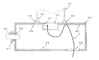
以下添付図面を参照して、本発明に係るボイラ装置の実施形態を説明する。各図において同一の構成要素には同一の符号を付して重複する説明を省略する。本実施形態に係るボイラ装置は、図1に示すように構成される。即ち、本実施形態に係るボイラ装置は、焼却対象材料11を上部の投入口22から投入し、底部23から堆積して貯留するための1次燃焼室である貯留槽21を備える。
Hereinafter, an embodiment of a boiler device according to the present invention will be described with reference to the accompanying drawings. In the drawings, the same components are denoted by the same reference numerals, and redundant description is omitted. The boiler device according to the present embodiment is configured as shown in FIG. That is, the boiler apparatus according to the present embodiment includes a
焼却対象材料11は、木材チップやもみ殻などが好的であるが、水分量が約30%以下のものであれば、ゴミ(廃棄物)などを許容する。貯留槽21は、投入口22の開口が底部23の底面積より遥かに大きく形成されており、投入口22の開口面積は底部23の底面積の4倍程度とすることができる。
The
投入口22には、平面形状が四角形の蓋24が設けられている。蓋24の奥側の一辺にはヒンジ28が設けられ、奥側の一辺と直交する2辺には、ワイヤ31を固定する耳状片32が形成されている。ワイヤ31はボイラ装置の側部の外側に立設された2本の支柱間に設けられパイプに結合されたプーリ33を介してモータ34により回転させられる巻取棒35に巻回されている。このような構成を有するため、図示しないコントローラによりモータ34をワイヤ31が巻取棒35に巻き取られる方向へ回転させると、耳状片32がワイヤ31に引っ張られて、ヒンジ28が設けられている蓋24の一辺を中心に矢印Xに示すように回転し、投入口22が開口される。逆に、図示しないコントローラによりモータ34をワイヤ31が巻取棒35から引き出される方向へ回転させると、蓋24の耳状片32側が上記矢印Xとは逆方向に下降し、投入口22を閉じる。このように、本実施形態では、蓋24を開閉するための蓋開閉手段が設けられている。
The
貯留槽21の正面側の底部23には、着火バーナ38が挿抜可能に設けられている。着火バーナ38は、貯留槽21に貯留された焼却対象材料11の底部に着火させるものである。着火後には、着火バーナ38を貯留槽21内から退避させるためのスライド台39に着火バーナ38が載置されている。着火バーナ38の先端を貯留槽21内に挿抜する穴には、着火バーナ38を貯留槽21内から退避させた後に上記穴を閉成するための、シャッタが設けられている。
An
上記貯留槽21における底部23側の側壁には連絡口41が形成されている。連絡口41は、横方向に例えば四角筒状に形成することができる。貯留槽21には連絡口41を介して、下部2次燃焼室42が結合されている。連絡口41には、焼却対象材料11の貯留槽21から下部2次燃焼室42への移動を妨げる火格子が設けられている。下部2次燃焼室42は上方へ向かって延びる四角筒形状の側壁によって形成される。このような構成により、下部2次燃焼室42には、火格子を介して貯留槽21側から燃焼に必要な熱と可燃ガスが到来し、下部2次燃焼室42において可燃ガスの一部が燃焼する。
A
上記下部2次燃焼室42の上部には、上記下部2次燃焼室42までに発生する可燃ガスを、取り入れ、上方へ向かわせる上部2次燃焼室43が設けられている。上部2次燃焼室43は、図2に断面図を示すように、四角筐体形状であり、底板44と天井板45とを有する。
An upper
天井板45における中央部には、円形状の開口46が形成されており、この開口46の周縁部から上部2次燃焼室43の内側へ向かって突出した円筒状のスリーブ47が形成されている。一方、底板44の外周部分には、可燃ガスを取り込むための穴48が形成されている。この構成によって、上部2次燃焼室43は、上記下部2次燃焼室42までに発生する可燃ガスを、底板44の外周側の穴48から取り入れ、上方へ向かわせて天井板45へ衝突させて下降させた後に上記天井板45の中央口である開口46から上方の煙突方向へ導くように機能する。即ち、可燃ガスは矢印Yに示されるように導かれる。穴48は、底板44の外周部分に複数形成されていても良い。
A
上部2次燃焼室43は、下部2次燃焼室42の上部の2次燃焼室の機能を有する。このため、上部2次燃焼室43の側壁には、焼却用バーナ51の先端部を挿入する穴52が形成され、この穴52から外側の外壁にはフランジ53が設けられている。
The upper
上部2次燃焼室43における天井板45の開口46の外側には、煙突61を載置して結合するための台座54が取り付けられている。本実施形態では、上部2次燃焼室43を一層とするが、複数層とする場合には、下層となる上部2次燃焼室43において、台座54を左右の側壁近くの天井板45における上面へ配置する。これによって、上層と下層の間には、台座54により空室ができ、下層の上部2次燃焼室43の天井板45の中央口である開口46から上記空室へ可燃ガスが到達する。更に、この空室から可燃ガスは、上層の上部2次燃焼室43における底板44の外周側の穴48から上層の上部2次燃焼室43内部へ取り入れられる。
On the outside of the
以上のように、下部2次燃焼室42と上部2次燃焼室43とは、上記貯留槽21の底部側の側壁に形成された連絡口41を介して上記貯留槽21と結合され、上記貯留槽21において上記焼却対象材料11の燃焼により発生する可燃ガスを燃焼させ、上方の煙突61方向へ導く2次燃焼室として機能する。
As described above, the lower
前述の通り、上部2次燃焼室43における天井板45の開口46の外側には、台座54が取り付けられている。この台座54には、煙突61が結合されている。上部2次燃焼室43の天井板45における上面から煙突61の上部の所定距離の位置には、水平方向に広がる載置台62が設けられている。この載置台62は、前述のプーリ33を貫通するパイプを支持する2本の柱及びこの2本の柱に対し煙突61を介して反対側にこの載置台62上であって煙突61から熱的に離れた位置には、ブロア65が取り付けられている。ブロア65からはパイプ66が上方向へ延びており、煙突61内に入り込んでいる。この構成によって、ブロア65は、煙突61内において約800℃の排ガスを約200℃以下まで急冷させる空気流を送出する。
As described above, the
貯留槽21の上方から底部23側を目視した断面図である図3に示すように、貯留槽21の底部に近い位置であって、正面中央を挟んで左右の2か所と左壁の中央部と右壁の中央部とには、外気を取り込む外気取込口71〜74が設けられている。下部2次燃焼室42の上方から底部側を目視した断面図である図4に示すように、下部2次燃焼室42の底部に近い位置であって、左壁の中央部と右壁の中央部とには、外気を取り込む外気取込口75〜76が設けられている。また、上部2次燃焼室43の上方から底部側を目視した断面図である図5に示すように、上部2次燃焼室43の左壁の中央部と右壁の中央部とには、外気を取り込む外気取込口77〜78が設けられている。これらの外気取込口71〜78は、同様の構成とすることができる。
As shown in FIG. 3, which is a cross-sectional view of the bottom 23 side as viewed from above the
外気取込口71〜78について、図6と図7を参照して、外気取込口71を代表として構成を説明する。外気取込口71の開口部81は、外側へ突出し、端面がフランジに形成されている。開口部81のフランジには、回転軸により回動自在に蓋体82が設けられている。蓋体82には、蓋体82を回転軸88を中心として回動させるための把手83が設けられている。開口部81から貯留槽21内または下部2次燃焼室42内または上部2次燃焼室43内へ僅かに(例えば、50mm〜80mm)進んだ位置には、室の壁の内側から突出するように設けられたスタッド84に平板85が固着されている。平板85には、空気を流すための貫通口86が形成されている。平板85は、室の壁面より小さく構成されている。このため、外気は、正面に設けられた直接流入防止手段である平板85へ一度当ててから内部へ流入させるように構成されている。
The configuration of the outside
なお、貯留槽21、下部2次燃焼室42、上部2次燃焼室43には、温度計や炭酸ガスやダイオキシンのセンサなどを設けて温度を外部から確認できるようにすることが好的である。また、貯留槽21、下部2次燃焼室42、上部2次燃焼室43には、内部を覗くための窓や点検用扉が設けられると好的である。
The
90は、湯沸室を示す。湯沸室90は、上記連絡口41の外側に接すると共に上記連絡口41側において上記貯留槽21の外壁に接して設けられ、給水口91から供給される水を加熱して排出するものである。湯沸室90は、図9と図10に示すように、連絡口41の底部に下方から接する底部位部分92と、連絡口41の天井部に上方から接する中部位部分93と、中部位部分93の更に上側に設けられた上部位部分94とを有する。
底部位部分92内には、給水口91から延びるパイプ95が設けられている。給水口91から供給された水はパイプ95へ到り、パイプ95の上部に長手方向に並んで形成された孔から底部位部分92内へ流れ出る。底部位部分92内へ流れ出た水は、連絡口41の側部に位置する流路部96を介して上方の中部位部分93へ到る。
A
中部位部分93と上部位部分94との間には、孔が形成された仕切板97が設けられている。従って、中部位部分93が水で満たされると、上記仕切板97の孔を介して上部位部分94へ水が流入し、その後に上部位部分94が水によって満たされる。
A
上部位部分94における天井部の排出口には、3本のパイプ98が上方へ延びるように連結されている。3本のパイプは横方向へ延びる排水パイプ99へつながっている。このため、上部位部分94が水で満たされると、水は、3本のパイプ98及び排水パイプ99を介して排出される。
Three
図1の100は、熱交換器である。熱交換器100は、煙突61の外側に接する円筒状の貯水室101を有し、入口102から供給される水を加熱して出力するものである。熱交換器100は、煙突61の内部に円柱状の加熱部103を備える。加熱部103と貯水室101とは、上部において上部連絡管104、104によって連絡されており、また、下部において下部連絡管105、105によって連絡されている。
1 in FIG. 1 is a heat exchanger. The
貯水室101の上部の出口には、排出パイプ106が接続されており、貯水室101の温水は排出パイプ106へ排出される。以上の構成を有する熱交換器100では、入口102から水が供給されると、貯水室101の下部へ蓄積され、下部連絡管105、105を介して加熱部103の下部にも水が蓄積されて行く。水の供給が進むと、水は貯水室101内と加熱部103内に蓄積されて水位が上昇して行き、貯水室101の最上部へ到ると、排出パイプ106へ排出される。
A
上記排水パイプ106はパイプ107を介して結合部108において湯沸室90側の排水パイプ99と結合される。結合部108にはパイプ109が接続され、パイプ109にはパイプ110が接続され排出側共通結合部111を介して湯水が供給先へ導かれる。
The
即ち、上記湯沸室90の排水口に第1の配管であるパイプ98及び排水パイプ99が接続され、上記熱交換器100の出口には第2の配管である排水パイプ106及びパイプ107が接続され、上記第1の配管であるパイプ98及び排水パイプ99と上記第2の配管である排水パイプ106及びパイプ107とが結合部108において結合されて湯水が供給先へ導かれる。
That is, a
排出側共通結合部111に隣接して供給側共通結合部112が設けられ、例えば水道水が供給側共通結合部112に供給されている。供給側共通結合部112からはパイプ113、114を介して熱交換器100の入口102まで水が供給される。また、供給側共通結合部112からはパイプ115、116を介して給水口92まで水が供給される。
A supply side
以上のように構成されたボイラ装置は、図7のフローチャートに示す手順で燃焼が進められる。投入口22の蓋24を開けて焼却対象材料11を貯留槽21に投入し、例えば満杯とした後に蓋24を閉成する(S11)。外気取込口71〜78の開口度を調整し、ブロア65による送気開始し、着火バーナ38を点火し、焼却用バーナ51を点火する(S12)。温度計などにより焼却対象材料11に着火し下部2次燃焼室42などにおける燃焼の確認ができると、着火バーナ38を退避させる(S13)。
In the boiler apparatus configured as described above, combustion proceeds in the procedure shown in the flowchart of FIG. The
以下、温度計などにより燃焼状態を確認し、必要があれば外気取込口71〜75の開口度を調整しても良く、また、必要があれば投入口22の蓋24を開けて焼却対象材料11を貯留槽21に投入しても良い。更に、燃焼を終了するときには、焼却対象材料11が完全に燃焼して自然に消火するのを待つか、外気取込口71〜75の開口度を完全に閉じて焼却用バーナ51を消火し、温度計などにより確認しながら完全に消火するのを待つようにすることができる(S14)。
Hereinafter, the combustion state is confirmed with a thermometer, etc., and if necessary, the opening degree of the
上記に対し、湯沸室90と上記熱交換器100に対する水の供給及び供給停止の制御は、図11のフローチャートに示されるように行われる。即ち、着火バーナ38による点火が行われる所定時間前に、所定量ずつ水の供給を開始する(S21)。そして、燃焼炉側において消火がなされるのを待つ(S22)。
In contrast, the water supply and supply stop control for the
ステップS22において消火がなされたことが検出されると、このときから所定時間の経過を待って水の供給を停止する(S23)。 When it is detected in step S22 that the fire has been extinguished, the supply of water is stopped after the elapse of a predetermined time from this time (S23).
以上の通り、貯留槽21、下部2次燃焼室42、上部2次燃焼室43、煙突61、ブロア65、外気取込口71〜75の位置と構成によって、貯留槽21において発生した可燃ガスは、勢い良く下部2次燃焼室42と上部2次燃焼室43へ進み燃焼されて排ガスとなって煙突61からは排出される。貯留槽21において生じる可燃ガスが投入口22へ流れることを防止し、小型でありながら高効率で燃焼の途中で新たな焼却対象材料11を供給する作業を容易にできる。
As described above, the combustible gas generated in the
また、外気取込口71〜75の構成が、外気を、該外気取込口71〜75の正面に設けられた直接流入防止手段である平板85へ一度当ててから内部へ流入させるように構成されているので、内部の暖められている平板85へ当たって暖められる。この暖められた外気が室内に入ることになるので、取り入れた外気が温度を低下させることがなく、効率的な燃焼を確保することができる。
Further, the configuration of the outside
更に、湯沸室90と上記熱交換器100とを用いて温水を得るようにしており、無駄のない熱利用を図ることができる。特に、貯留槽21と2次燃焼室との連絡口41の部分から湯沸室90により熱を得て湯沸しを行うので極めて効率的である。
Furthermore, hot water is obtained using the
また、湯沸室90の排水口に第1の配管であるパイプ98及び排水パイプ99が接続され、熱交換器100の出口には第2の配管である排水パイプ106及びパイプ107が接続され、上記第1の配管と上記第2の配管とが結合されて湯水が供給先へ導かれるので、熱交換器100により得られる高温の温水と湯沸室90において得られる熱交換器100よりも低温の温水を混合して適当な温度とすることも可能となっている。
In addition, a
11 焼却対象材料
21 貯留槽
22 投入口
23 底部
24 蓋
31 ワイヤ
32 耳状片
33 プーリ
34 モータ
35 巻取棒
38 着火バーナ
39 スライド台
41 連絡口
42 下部2次燃焼室
43 上部1次燃焼室
44 底板
45 天井板
46 開口
47 スリーブ
48 穴
51 焼却用バーナ
52 穴
53 フランジ
54 台座
61 煙突
62 載置台
65 ブロア
66 パイプ
71 外気取込口
81 開口部
82 蓋体
83 把手
84 スタッド
85 平板
86 貫通口
90 湯沸室
100 熱交換器
101 貯水室
11
Claims (6)
前記貯留槽の底部側の側壁に形成された連絡口を介して前記貯留槽と結合され、前記貯留槽において前記焼却対象材料の燃焼により発生する可燃ガスを燃焼させ、上方の煙突方向へ導く2次燃焼室と、
前記連絡口の底部に下方から接する底部位部分と、前記連絡口の天井部に上方から接する中部位部分と、前記中部位部分の更に上側に設けられた上部位部分とを有すると共に前記上部位部分の前記貯留槽側の側壁が上記貯留槽の外壁に接して設けられ、給水口から供給される水を加熱して排出する湯沸室と、
前記煙突の外側に接する貯水室を有し、入口から供給される水を加熱して出力する熱交換器と
を具備することを特徴とするボイラ装置。 A storage tank that is a primary combustion chamber for charging a material to be incinerated from the top inlet, and depositing and storing from the bottom; an ignition burner that ignites the bottom of the material to be incinerated stored in the storage tank; ,
2 connected to the storage tank via a communication port formed on the side wall on the bottom side of the storage tank, in which combustible gas generated by combustion of the material to be incinerated is burned in the storage tank, and is directed to the upper chimney direction 2 The next combustion chamber,
The upper part has a bottom part part contacting the bottom part of the communication port from below, a middle part part contacting the ceiling part of the communication port from above, and an upper part part provided further above the middle part part A side wall of the storage tank side of the part is provided in contact with the outer wall of the storage tank, and a water heating chamber for heating and discharging water supplied from a water supply port;
A boiler apparatus comprising: a water storage chamber in contact with the outside of the chimney, and a heat exchanger that heats and outputs water supplied from an inlet.
前記湯沸室は、その下部に給水口が設けられ、その上部に排水口が設けられていることを特徴とする請求項1に記載のボイラ装置。 The heat exchanger is provided with a water inlet at the bottom and a water outlet at the top,
The boiler apparatus according to claim 1, wherein the water heater has a water supply port at a lower portion thereof and a drain port at an upper portion thereof.
前記熱交換器の出口には第2の配管が接続され、
前記第1の配管と前記第2の配管とが結合されて湯水が供給先へ導かれることを特徴とする請求項2に記載のボイラ装置。 A first pipe is connected to the drain of the water heating chamber;
A second pipe is connected to the outlet of the heat exchanger,
The boiler apparatus according to claim 2 , wherein the first pipe and the second pipe are combined to guide hot water to a supply destination.
前記貯留槽の底部側の側壁に形成された連絡口を介して前記貯留槽と結合され、前記貯留槽において前記焼却対象材料の燃焼により発生する可燃ガスを燃焼させる下部2次燃焼室と、
前記下部2次燃焼室の上部に設けられ、2次燃焼を行うと共に前記下部2次燃焼室までに発生する可燃ガスを、底部の外周側から取り入れ、上方へ向かわせて天井部へ衝突させて下降させた後に前記天井部の中央口から上方の煙突方向へ導く上部2次燃焼室と、
により構成されることを特徴とする請求項1乃至3のいずれか1項に記載のボイラ装置。 The secondary combustion chamber is
A lower secondary combustion chamber that is connected to the storage tank via a communication port formed on a bottom side wall of the storage tank and burns combustible gas generated by combustion of the incineration target material in the storage tank;
Provided in the upper part of the lower secondary combustion chamber, performs the secondary combustion and takes in the combustible gas generated up to the lower secondary combustion chamber from the outer peripheral side of the bottom part, and makes it collide with the ceiling part upward. An upper secondary combustion chamber that is guided downward from the central opening of the ceiling portion to the upper chimney direction;
The boiler device according to any one of claims 1 to 3, wherein the boiler device is configured by.
を具備することを特徴とする請求項1乃至5のいずれか1項に記載のボイラ装置。 The boiler device according to any one of claims 1 to 5, further comprising a blower for sending air into the chimney.
Applications Claiming Priority (2)
| Application Number | Priority Date | Filing Date | Title |
|---|---|---|---|
| JP2017091995 | 2017-05-02 | ||
| JP2017091995 | 2017-05-02 |
Publications (2)
| Publication Number | Publication Date |
|---|---|
| JP2018189317A JP2018189317A (en) | 2018-11-29 |
| JP6484663B2 true JP6484663B2 (en) | 2019-03-13 |
Family
ID=64478285
Family Applications (1)
| Application Number | Title | Priority Date | Filing Date |
|---|---|---|---|
| JP2017092753A Active JP6484663B2 (en) | 2017-05-02 | 2017-05-09 | Boiler equipment |
Country Status (1)
| Country | Link |
|---|---|
| JP (1) | JP6484663B2 (en) |
Family Cites Families (6)
| Publication number | Priority date | Publication date | Assignee | Title |
|---|---|---|---|---|
| JPS5680402U (en) * | 1979-11-20 | 1981-06-30 | ||
| JPH0277428U (en) * | 1989-11-01 | 1990-06-14 | ||
| JPH0417228U (en) * | 1990-05-31 | 1992-02-13 | ||
| JP3378363B2 (en) * | 1994-07-22 | 2003-02-17 | 株式会社よしみね | Wet solid continuous incinerator |
| JP2000193216A (en) * | 1998-12-25 | 2000-07-14 | Yukio Fujimura | Incinerator |
| JP2007147176A (en) * | 2005-11-29 | 2007-06-14 | Takao Ueshima | Incinerator |
-
2017
- 2017-05-09 JP JP2017092753A patent/JP6484663B2/en active Active
Also Published As
| Publication number | Publication date |
|---|---|
| JP2018189317A (en) | 2018-11-29 |
Similar Documents
| Publication | Publication Date | Title |
|---|---|---|
| KR100917787B1 (en) | Hot air blower for solid fuel | |
| KR101079694B1 (en) | A firewood boiler | |
| KR101288589B1 (en) | The firewood and wood-pellet boiler | |
| KR101363689B1 (en) | Pellet boiler | |
| KR101564844B1 (en) | Pellet stove with high efficiency | |
| JP6484663B2 (en) | Boiler equipment | |
| KR200446195Y1 (en) | The hot-water boiler with a wood pellet | |
| KR101541535B1 (en) | Wood combustor for heating | |
| KR200400023Y1 (en) | Wood boiler | |
| KR101148696B1 (en) | Wood-pellet boiler | |
| KR101709583B1 (en) | Multipurpose firewood stove | |
| KR100796434B1 (en) | Fuel save boiler | |
| KR101958092B1 (en) | The firewood steam boiler of flue tube-smoke type | |
| JP6484662B2 (en) | Combustion furnace | |
| KR101958087B1 (en) | The firewood steam boiler of flue tube-smoke type | |
| JP3129658U (en) | Incinerator | |
| JP3127566U (en) | Incinerator | |
| KR101809896B1 (en) | Solidfuel of boiler | |
| KR100858040B1 (en) | Boiler | |
| KR200437991Y1 (en) | Boiler with separated brazier and water tank | |
| KR20120087461A (en) | Boiler | |
| KR101483879B1 (en) | A stovepipe-less type stove | |
| KR101325663B1 (en) | Combustion device for fire wood boiler | |
| EP2886953B1 (en) | Wood stove with a supply duct for logs | |
| KR102035114B1 (en) | Hot air heater |
Legal Events
| Date | Code | Title | Description |
|---|---|---|---|
| A601 | Written request for extension of time |
Free format text: JAPANESE INTERMEDIATE CODE: A601 Effective date: 20180904 |
|
| RD02 | Notification of acceptance of power of attorney |
Free format text: JAPANESE INTERMEDIATE CODE: A7422 Effective date: 20180904 |
|
| A521 | Request for written amendment filed |
Free format text: JAPANESE INTERMEDIATE CODE: A523 Effective date: 20181113 |
|
| TRDD | Decision of grant or rejection written | ||
| A01 | Written decision to grant a patent or to grant a registration (utility model) |
Free format text: JAPANESE INTERMEDIATE CODE: A01 Effective date: 20190212 |
|
| A61 | First payment of annual fees (during grant procedure) |
Free format text: JAPANESE INTERMEDIATE CODE: A61 Effective date: 20190218 |
|
| R150 | Certificate of patent or registration of utility model |
Ref document number: 6484663 Country of ref document: JP Free format text: JAPANESE INTERMEDIATE CODE: R150 |
|
| R250 | Receipt of annual fees |
Free format text: JAPANESE INTERMEDIATE CODE: R250 |
|
| R250 | Receipt of annual fees |
Free format text: JAPANESE INTERMEDIATE CODE: R250 |
|
| R250 | Receipt of annual fees |
Free format text: JAPANESE INTERMEDIATE CODE: R250 |