JP6482811B2 - Tail clearance measuring device - Google Patents
Tail clearance measuring device Download PDFInfo
- Publication number
- JP6482811B2 JP6482811B2 JP2014202843A JP2014202843A JP6482811B2 JP 6482811 B2 JP6482811 B2 JP 6482811B2 JP 2014202843 A JP2014202843 A JP 2014202843A JP 2014202843 A JP2014202843 A JP 2014202843A JP 6482811 B2 JP6482811 B2 JP 6482811B2
- Authority
- JP
- Japan
- Prior art keywords
- segment
- clearance
- tail
- unit
- detection light
- Prior art date
- Legal status (The legal status is an assumption and is not a legal conclusion. Google has not performed a legal analysis and makes no representation as to the accuracy of the status listed.)
- Active
Links
- 238000001514 detection method Methods 0.000 claims description 138
- 230000002093 peripheral effect Effects 0.000 claims description 79
- 238000005259 measurement Methods 0.000 claims description 65
- 230000003287 optical effect Effects 0.000 claims description 32
- 239000013307 optical fiber Substances 0.000 claims description 30
- 238000009412 basement excavation Methods 0.000 claims description 28
- 238000003384 imaging method Methods 0.000 claims description 19
- 238000009795 derivation Methods 0.000 claims description 15
- 238000006073 displacement reaction Methods 0.000 claims description 13
- 238000003825 pressing Methods 0.000 claims description 5
- 238000004891 communication Methods 0.000 description 16
- 238000009434 installation Methods 0.000 description 14
- 238000000034 method Methods 0.000 description 10
- 230000008569 process Effects 0.000 description 10
- 238000012545 processing Methods 0.000 description 9
- 230000000694 effects Effects 0.000 description 7
- 238000005286 illumination Methods 0.000 description 7
- 230000005540 biological transmission Effects 0.000 description 4
- 230000008859 change Effects 0.000 description 4
- 239000003673 groundwater Substances 0.000 description 4
- 238000012986 modification Methods 0.000 description 4
- 230000004048 modification Effects 0.000 description 4
- 238000010586 diagram Methods 0.000 description 3
- 238000006243 chemical reaction Methods 0.000 description 2
- 230000007423 decrease Effects 0.000 description 2
- 238000004364 calculation method Methods 0.000 description 1
- 238000005553 drilling Methods 0.000 description 1
- 238000005516 engineering process Methods 0.000 description 1
- 230000002708 enhancing effect Effects 0.000 description 1
- 238000010191 image analysis Methods 0.000 description 1
- 230000001678 irradiating effect Effects 0.000 description 1
- 238000005192 partition Methods 0.000 description 1
- 238000007781 pre-processing Methods 0.000 description 1
- 230000004044 response Effects 0.000 description 1
- 239000004576 sand Substances 0.000 description 1
- 239000002689 soil Substances 0.000 description 1
Images


Description
本発明はテールクリアランス測定装置に関する。 The present invention relates to a tail clearance measuring device.
テール部の内側でセグメントを円筒壁状に組み立てつつ掘進することでセグメントトンネルを組み立てるシールドマシンがある。
シールドマシンのテール部の内周面と、テール部の内側に位置するセグメントの外周面とのクリアランス(テールクリアランス)は、シールドマシンの掘進方向と既に組み立てられたセグメントとの相対的な位置関係に応じて変化する。
したがって、テールクリアランスを測定し、その測定値をシールドマシンの掘進方向を制御するためのデータとして用いたり、あるいは、セグメント組み立てを行うためのデータとして用いている。
従来、テールクリアランスの測定は、シールドマシンによる掘進作業の前後に、作業員がスケールを用いて行うか、あるいは、専用の計測装置をセグメントに位置決め固定し、計測装置から突出する測針をスキンプレートに当て付け、測針の突出量に基づいてテールクリアランスを測定していた(特許文献1参照)。
There is a shield machine that assembles a segment tunnel by digging while assembling the segment into a cylindrical wall inside the tail part.
The clearance (tail clearance) between the inner peripheral surface of the tail part of the shield machine and the outer peripheral surface of the segment located inside the tail part is the relative positional relationship between the direction of the shield machine and the already assembled segment. Will change accordingly.
Therefore, the tail clearance is measured, and the measured value is used as data for controlling the direction of excavation of the shield machine, or is used as data for performing segment assembly.
Conventionally, tail clearance measurement is performed by an operator using a scale before or after excavation work with a shield machine, or a dedicated measuring device is positioned and fixed to a segment, and the needle that protrudes from the measuring device is attached to the skin plate. The tail clearance was measured based on the amount of protrusion of the needle (see Patent Document 1).
しかしながら、上述したスケールによる従来の技術では、測定に際しては掘進動作を停止した状態で作業員による測定作業を行う必要があるため、掘進中の測定データを得ることが困難であり、測定効率の低下を招く不利があった。また、測針の突出量に基づいてテールクリアランスを測定する計測装置を用いる場合には計測装置が故障しやすく測定効率の低下を招く不利があった。
また、セグメント内部が大口径の場合は高所作業が必要となり、また、セグメント内部が小口径の場合は狭小スペースでの作業が必要となることから、作業員の身体的な負担が大きなものとなる不利があった。
本発明はこのような事情に鑑みなされたものであり、その目的は、測定効率の向上を図る上で、また、作業員の負担の軽減を図る上で有利なテールクリアランス測定装置を提供することにある。
However, in the conventional technology based on the scale described above, it is necessary to perform measurement work by an operator in a state where the excavation operation is stopped at the time of measurement, so it is difficult to obtain measurement data during excavation, and the measurement efficiency decreases. There was a disadvantage inviting. Further, when using a measuring device that measures the tail clearance based on the protruding amount of the metering, there is a disadvantage that the measuring device is likely to break down and the measurement efficiency is lowered.
In addition, if the inside of the segment has a large diameter, work at a high place is required, and if the inside of the segment has a small diameter, work in a narrow space is required, which places a heavy burden on the worker. There was a disadvantage.
The present invention has been made in view of such circumstances, and an object of the present invention is to provide a tail clearance measurement device that is advantageous in improving measurement efficiency and reducing the burden on workers. It is in.
上述の目的を達成するため、本発明は、シールドマシンのテール部の内周面と、前記内周面の内側に位置するセグメントの外周面とのクリアランスを測定するテールクリアランス測定装置であって、前記テール部で支持され、前記セグメントの端面上で前記セグメントの半径方向に延在するセグメント端面領域と前記セグメントの内周面または外周面の一方とが交わる円弧部分に交差し前記端面上を延在する線状の第1の検出光を前記セグメント端面領域に投射する検出光投射部と、少なくとも撮影光学系が前記テール部で支持され、前記第1の検出光を含む前記セグメント端面領域を撮影して画像情報を生成するカメラ部と、前記画像情報に基づいて前記テール部の内周面と前記セグメントの外周面とのクリアランスを導出するクリアランス導出部とを備え、前記第1の検出光に対して前記円弧部分が交差する交点を第1の交点とした場合、前記クリアランス導出部による前記クリアランスの導出は、予め前記シールドマシンによる掘削を開始する前に手作業により実測された前記テール部の内周面と前記セグメントの外周面との初期テールクリアランスと、前記第1の交点の変位量とに基づいてなされ、前記第1の検出光に対して前記セグメント端面領域と前記セグメントの内周面または外周面の他方とが交わる円弧部分が交差する交点を第2の交点とした場合、前記検出光投射部は、前記セグメント端面領域に前記第1の検出光に加え、前記第1の検出光に直交する方向に延在する第2の検出光を投射し、前記クリアランス導出部は、前記第2の検出光に対する前記第1の交点の位置と前記第2の交点との位置とが異なることに基づいて前記第1の交点を特定することを特徴とする。 In order to achieve the above object, the present invention is a tail clearance measuring device for measuring a clearance between an inner peripheral surface of a tail part of a shield machine and an outer peripheral surface of a segment located inside the inner peripheral surface, The segment is supported by the tail portion and extends on the end surface crossing an arc portion where the segment end surface region extending in the radial direction of the segment on the end surface of the segment intersects one of the inner peripheral surface or the outer peripheral surface of the segment. A detection light projection unit that projects the existing linear first detection light onto the segment end surface region, and at least a photographing optical system is supported by the tail portion, and images the segment end surface region including the first detection light. And a clear run for deriving a clearance between the inner peripheral surface of the tail portion and the outer peripheral surface of the segment based on the image information. And a deriving unit, when said intersections, wherein the arcuate portion to the first detection light intersects the first intersection, the derivation of the clearance by the clearance deriving unit, start drilling by advance the shield machine The first detection light is generated based on the initial tail clearance between the inner peripheral surface of the tail portion and the outer peripheral surface of the segment and the amount of displacement of the first intersection, which are measured manually before On the other hand, when the intersection point where the arc portion where the segment end surface region and the other one of the inner peripheral surface or the outer peripheral surface of the segment intersect is defined as a second intersection point, the detection light projection unit is arranged in the segment end surface region. In addition to the first detection light, a second detection light extending in a direction orthogonal to the first detection light is projected, and the clearance deriving unit is configured to project the first intersection with respect to the second detection light. And identifies the first intersection based on the position of the position of the second intersection point are different.
検出光投射部によりセグメント端面領域とセグメントの内周面または外周面の一方とが交わる第1の円弧部分に交差し端面上を延在する線状の第1の検出光をセグメント端面領域に投射すると共に、カメラ部によって撮像された第1の検出光を含むセグメント端面領域の画像情報に基づいてテールクリアランスを導出するようにした。
したがって、シールドマシンの掘進動作を停止することなく掘進中の測定データを連続して得ることができるため、測定効率の向上を図る上で有利となり、作業員による測定作業が不要となるため、作業員の身体的な負担の軽減を図る上でも有利となる。
また、照明が暗い環境下であっても、カメラ部は、セグメント端面で反射された検出光を反射光として確実に撮像することができるので、テールクリアランスを高精度にかつ安定して導出する上でより一層有利となる。
The detection light projection unit projects linear first detection light that intersects the first arc portion where the segment end surface region and one of the inner peripheral surface or the outer peripheral surface of the segment intersect and extends on the end surface onto the segment end surface region. In addition, the tail clearance is derived based on the image information of the segment end face region including the first detection light imaged by the camera unit.
Therefore, the measurement data during excavation can be obtained continuously without stopping the excavation operation of the shield machine, which is advantageous in improving measurement efficiency and eliminates the need for measurement work by workers. It is also advantageous in reducing the physical burden on the staff.
In addition, even in a dark environment, the camera unit can reliably capture the detection light reflected from the segment end face as reflected light, so that the tail clearance can be derived with high accuracy and stability. Is even more advantageous.
(第1の実施の形態)
次に本発明の実施の形態について図1〜図8を参照して説明する。
まず、シールドマシン10について説明する。
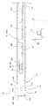
図1、図2に示すように、シールドマシン10は、前胴部12と、テール部(後胴部)14と、後方台車16などを含んで構成され、前胴部12は、掘削部12Aと、その後方に設けられた後部室12Cとを有している。
(First embodiment)
Next, an embodiment of the present invention will be described with reference to FIGS.
First, the
As shown in FIGS. 1 and 2, the
掘削部12Aは、カッター(カッター装置)1202、外装壁(トンネル18の内壁1802に臨む前スキンプレート)12Bなどから構成されている。
後部室12Cは、前スキンプレート12Bの内側で掘削部12Aの後方の箇所であり、後部室12Cには、不図示のコンベア装置(排土装置)、ジャッキ装置などが配置されている。
カッター1202は、円盤状のカッタを掘進方向と平行な軸線回りに回転することで地山を掘削するように構成されている。
コンベア装置は、カッター1202による地山の掘削で排出された土砂を後方に運搬するように構成されている。
ジャッキ装置は、カッター1202によって掘削されたトンネル18に環状に組み付けられるセグメント20の端面箇所を上記掘進方向の後方に向けて押圧することでカッター1202とコンベア装置を掘進方向に推進させるように構成されている。
テール部14には、後部室12Cとテール部14とを区画する環状の壁部14Bが設けられており、壁部14Bは、後述するセグメント20の端面2006と対向している。
また、テール部14では、セグメント20の組み立てが行われる。
The
The
The
The conveyor device is configured to convey the earth and sand discharged by excavation of natural ground by the
The jack device is configured to push the
The
Further, in the
テール部14は、トンネル18の内壁1802に臨むスキンプレート(後スキンプレート)14Aなどを備えている。
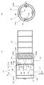
図2(A)、(B)に示すように、スキンプレート14Aは円筒状を呈し、トンネル18の内壁1802に臨む外周面と該外周面と対向しセグメント20の外周面2002に臨む内周面1402を有している。
テール部14は、前胴部12の後端に屈曲可能に結合されており、具体的には、テール部14のスキンプレート14Aが掘削部12Aの外装壁(前スキンプレート)12Bの前記掘進方向の後端部に屈曲可能に接続されている。
The
As shown in FIGS. 2A and 2B, the
The
後方台車16は、シールド機10を動作させるものであり、テール部14の後方において、テール部14で組み立てられたセグメントトンネル内に設けられている。
本実施の形態では、後方台車16は、複数の台車16A、16B、16C、16Dを備え、これら台車には、掘削部12Aとテール部14を動作させるための制御ユニット、駆動源、油タンクなどが分散して配設されている。
後方台車16は、トンネル18の長手方向に延在するレール19上を移動可能に設けられている。
The
In the present embodiment, the
The
セグメント20は、トンネル18の半径方向に延在する厚みと、トンネル18の掘進方向に延在する長さとを有している。
また、セグメント20は、図1、図6に示すように、トンネル18の内壁1802に臨ませて配設される円筒面状の外周面2002と、トンネル18の中心に臨む円筒面状の内周面2004と、トンネル18の延在方向の両端に位置する端面2006とを有して構成されている。
セグメント20は、シールド機10によって掘削されたトンネル18の内壁1802に、環状に組み付けられることによって、言い換えると坑内に組み付けられることによって、内壁1802を支える作用を果たす。
セグメント20が内壁1802に組み付けられることによってセグメントトンネルが構築される。
The
As shown in FIGS. 1 and 6, the
The
A segment tunnel is constructed by assembling the
(テールクリアランス測定装置30)
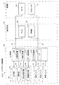
図1、図3に示すように、テールクリアランス測定装置30は、装置本体32と、コンピュータ34とを含んで構成されている。
本実施の形態では、装置本体32はテール部14に設置され、コンピュータ34はトンネル18から離れた場所に設けられた事務所2内に設置されている。
装置本体32とコンピュータ34とは、通信回線36を介して種々のデータを双方向に通信可能に構成されている。
本実施の形態では、通信回線36としてはケーブルを介した有線LANを用いているが、通信回線36としては、無線LANなどの無線回線を用いてもよく、通信回線36として従来公知のさまざまな形態の通信回線が使用可能である。
図3に示すように、後方台車16には、装置本体32の制御盤40から映像伝送線37を介して伝送される映像を表示するモニタ50と、通信回線36を介して供給される制御コマンドに応じて警報音を発生する警報部52とが設けられている。
また、事務所2には、コンピュータ34に加えて、制御盤40から映像伝送線37を介して伝送される映像を表示するモニタ54が設置されている。
なお、コンピュータ34の設置場所は限定されるものではなく、例えば、後方台車16に設置してもよいことは無論である。
(Tail clearance measuring device 30)
As shown in FIGS. 1 and 3, the tail
In the present embodiment, the apparatus
The apparatus
In the present embodiment, a wired LAN via a cable is used as the
As shown in FIG. 3, the
In addition to the
Note that the installation location of the
図3に示すように、装置本体32は、測定ユニット38と、制御盤40とを含んで構成されている。
本実施の形態では、測定ユニット38は4つ設けられている。
各測定ユニット38は、カメラ部42と、照明部43と、検出光投射部44と、距離検出部46とを備え、不図示の支持部材に一体的に固定され、支持部材を介してテール部14に取着されている。
本実施の形態では、各測定ユニット38は、後部室12C内で支持部材を介してテール部14の壁部14B(図2(A))に取着されている。
言い換えると、カメラ部42と検出光投射部44は、テール部14に移動不能に固定されている。
As shown in FIG. 3, the apparatus
In the present embodiment, four
Each
In the present embodiment, each
In other words, the
(カメラ部42)
図5(A)、(B)、図6(A)、(B)に示すように、カメラ部42は、後述する第1の検出光L1を含むセグメント端面領域Seを撮影して画像情報を生成するものである。
(Camera unit 42)
As shown in FIGS. 5A, 5B, 6A, and 6B, the
本実施の形態では、4つの測定ユニット38は、各カメラ部42が、テール部14の内周面1402の周方向に90度の間隔をおいた4箇所を撮影するように、テール部14の内周面1402の周方向に90度の間隔をおいて設けられている。
具体的には、図2(A)、(B)に示すように、測定ユニット38は、鉛直方向の上下2箇所と、鉛直方向と直交する水平方向の左右2箇所との4箇所に設けられている。
カメラ部42はカメラ本体42Aを有している。
カメラ本体42Aには撮影光学系が組み込まれたレンズ鏡筒42Bが設けられている。
カメラ本体42Aは、不図示の撮像素子と信号処理部を備えている。
前記撮像素子は、前記撮影光学系によって導かれた被写体像を撮像して撮像信号を生成するものであり、このような撮像素子としてCCDやC−MOSセンサなど従来公知の様々な撮像素子が使用可能である。
前記信号処理部は、前記撮像素子から供給される撮像信号を処理することにより映像信号を生成するものである。
In the present embodiment, the four
Specifically, as shown in FIGS. 2A and 2B, the
The
The
The
The image pickup device picks up a subject image guided by the photographing optical system and generates an image pickup signal. As such an image pickup device, various conventionally known image pickup devices such as a CCD and a C-MOS sensor are used. Is possible.
The signal processing unit generates a video signal by processing an imaging signal supplied from the imaging element.
(照明部43)
照明部43は、カメラ部42の撮像範囲を照明するものであり、例えばスポット照明装置で構成されている。
照明部43は、コンピュータ34から通信回線36、制御盤40を介して送信される制御コマンドにより点灯、滅灯が制御される。
このように照明部43を設けると、必要に応じて照明部43による照明を行わせることでモニタ50、54によって表示される映像の明るさやコントラストの向上を図り、視認性を高める上で有利となる。
(Lighting unit 43)
The
The
Providing the
(検出光投射部44)
検出光投射部44は、レーザー光源から出射されたレーザー光を特殊レンズを用いることにより線状の検出光として出射するものである。
本実施の形態では、4つの測定ユニット38は、各検出光投射部44が、セグメント20の端面2006の周方向に90度の間隔をおいた4箇所に検出光を投射するように、テール部14の内周面1402の周方向に90度の間隔をおいて設けられている。
このような検出光投射部44として、例えば、株式会社モリテックスから販売されているレーザーバターンプロジェクター(商品名)などが使用可能である。
検出光投射部44は、図5(A)、(B)、図6(A)、(B)に示すように、セグメント20の端面2006上でセグメント20の半径方向に延在するセグメント端面領域Seとセグメント20の内周面2004とが交わる第1の円弧部分C1に交差し、端面2006上を延在する線状の第1の検出光L1をセグメント端面領域Seに投射するものである。
本実施の形態では、第1の検出光L1は、さらに、セグメント20の端面2006上でセグメント20の半径方向を延在するセグメント端面領域Seとセグメント20の外周面2002とが交わる第2の円弧部分C2にも交差している。
また、検出光投射部44は、セグメント端面領域Seに第1の検出光L1に加え、第1の検出光L1に直交する方向に延在する第2の検出光L2を投射する。したがって、第1の検出光L1および第2の検出光L2は、十字状のクロスラインとしてセグメント端面箇所Seに投射される。
図7(A)〜(C)は、カメラ部42によって撮像された画像情報を示す図であり、符号Zは、カメラ部42の撮像エリアを示している。
このように、検出光投射部44からセグメント端面箇所Seに第1、第2の検出光L1、L2を投射するため、トンネル18内のように照明が暗い環境下であっても、カメラ部42は、セグメント端面箇所Seで反射された第1、第2の検出光L1、L2を反射光として確実に撮像することができる。
また、それら検出光L1、L2の波長範囲は、カメラ部42によって撮像できるものであればよいが、例えば、検出光L1、L2を赤色光とすれば視認性の向上を図る上で有利である。
(Detection light projection unit 44)
The detection
In the present embodiment, the four
As such a detection
As shown in FIGS. 5A, 5 </ b> B, 6 </ b> A, and 6 </ b> B, the detection
In the present embodiment, the first detection light L1 further includes a second arc in which the segment end surface region Se extending in the radial direction of the
In addition to the first detection light L1, the detection
7A to 7C are diagrams illustrating image information captured by the
As described above, since the first and second detection lights L1 and L2 are projected from the detection
The wavelength range of the detection lights L1 and L2 may be any wavelength that can be imaged by the
(距離検出部46)
距離検出部46は、テール部14とセグメント20の端面2006との距離を検出し、検出した距離を示す検出信号を制御盤40に供給するものである。
より詳細には、距離検出部46は、掘進部12の複数のジャッキ装置の少なくとも2台のジャッキ装置がセグメント20を掘進方向と反対方向に押圧する際のストローク量を検出するものである。
本実施の形態では、距離検出部46は、セグメント20の端面2006に検出光を照射し、その反射光を検出することにより距離(変位)を検出し、該距離に対応した電圧値を有する検出信号を制御盤40に供給する。この場合、検出信号はアナログ信号である。
なお、距離検出部46は非接触レーザー変位計に限定されるものではない。距離検出部46としては、掘進部12の複数のジャッキ装置にそれぞれ取着され、ジャッキ装置がセグメント20を掘進方向と反対方向に押圧する際のストローク量を検出するストロークセンサを用いてもよい。
(Distance detection unit 46)
The
More specifically, the
In the present embodiment, the
The
(制御盤40)
図3に示すように、制御盤40は、画像処理部40A、映像分配部40B、データ変換部40C、入出力制御部40D、インターフェース40Eなどを含んで構成されている。
画像処理部40Aは、各カメラ部42から供給される画像情報に対して後述する画像解析処理に必要な前処理を行うことによりデジタル化された画像情報を生成し、この画像情報を通信回線36を介してコンピュータ34に供給するものである。
映像分配部40Bは、各カメラ部42から供給される画像情報を切り換えてモニタ50、54に映像伝送線37を介して供給するものである。
データ変換部40Cは、距離検出部46から供給される前記ストローク量の検出信号をアナログ信号からデジタル信号に変換して通信回線36を介してコンピュータ34に供給するものである。
入出力制御部40Dは、コンピュータ34から通信回線36を介して供給される制御コマンドに応じて映像分配部40Bの切り換え動作を制御するものである。
インターフェース40Eは、画像処理部40A、映像分配部40B、データ変換部40C、入出力制御部40D、照明部43と、通信回線36との間での信号、データの送受信の制御を行うものである。
(Control panel 40)
As shown in FIG. 3, the
The
The video distribution unit 40B switches the image information supplied from each
The data converter 40C converts the stroke amount detection signal supplied from the
The input /
The interface 40E controls transmission / reception of signals and data between the
(コンピュータ34)
コンピュータ34は、各カメラ部42から制御盤40および通信回線36を介して供給される画像情報に基づいてテール部14の内周面1402とセグメント20の外周面2002とのクリアランスを導出するものである。
コンピュータ34は、図4に示すように、CPU3402と、不図示のインターフェース回路およびバスラインを介して接続されたROM3404、RAM3406、ハードディスク装置3408、ディスク装置3410、キーボード3412、マウス3414、ディスプレイ3416、プリンタ3418、インターフェース3420などを有している。
ROM3404は制御プログラムなどを格納し、RAM3406はワーキングエリアを提供するものである。
ハードディスク装置3408は従来公知の画像解析プログラム、テールクリアランスTcを導出する導出プログラム、テールクリアランスTcの監視プログラムを格納している。
ディスク装置3410はCDやDVDなどの記録媒体に対してデータの記録および/または再生を行うものである。
キーボード3412およびマウス3414は、操作者による操作入力を受け付けるものである。
ディスプレイ3416はデータを表示出力するものであり、プリンタ3418はデータを印刷出力するものであり、ディスプレイ3416およびプリンタ3418によってデータを出力する。
インターフェース3420は、通信回線36を介して各測定ユニット38から供給される画像情報を入力するものである。
CPU3402はハードディスク装置3408に格納されている画像解析プログラムおよび導出プログラムを実行することにより、インターフェース3420から入力された画像情報に基づいて、図2(B)に示すように、テール部14のスキンプレート14Aの内周面1402とセグメント20の外周面2002とのテールクリアランスTcを導出するものである。
したがって、本実施の形態では、画像解析プログラムおよび導出プログラムを実行するコンピュータ34のCPU3402によって特許請求の範囲のクリアランス導出部が構成されている。
さらに、CPU3402は、導出されたテールクリアランスTcをディスプレイ3416によって表示出力し、あるいは、プリンタ3418によって印刷出力するものである。
なお、CPU3402によるテールクリアランスTcの出力は、ディスク装置3410を用いてCDやDVDなどの記録媒体に対して行ってもよいし、コンピュータ34に設けられた種々の外部インターフェースを介してメモリカードに対して行ってもよい。あるいは、インターフェース3420を用いてネットワークを介して他のコンピュータ(端末装置)に対して行ってもよく、テールクリアランスTcの出力の形態は任意である。
(Computer 34)
The
As shown in FIG. 4, the
A
The
The
The
A
The
The
Therefore, in the present embodiment, the clearance derivation unit of the claims is constituted by the
Further, the
The output of the tail clearance Tc by the
また、CPU3402は、ハードディスク装置3408に格納されている前記監視プログラムを実行することにより、得られたテールクリアランスTcが予め定められた許容範囲を超えた場合に、警報動作の実行を指示する制御コマンドを、通信回線36を介して警報部52に供給する監視処理を実行するものである。
In addition, the
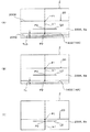
ここで、図7(A)〜(C)を参照して前記クリアランス導出部によるテールクリアランスTcの導出処理について説明する。
図7(A)は初期設定状態を示している。
前述したようにカメラ部42を含む測定ユニット38は、テール部14に一体的に固定されており、したがって、撮像エリアZとテール部14の内周面1402との相対的な位置関係は不変である。
図7(A)に示すように、第1の検出光L1は、第1の円弧部分C1および第2の円弧部分C2に交差して延在している。本実施の形態では、第1の検出光L1は、第1の円弧部分C1および第2の円弧部分C2と直交している。
Here, the derivation process of the tail clearance Tc by the clearance deriving unit will be described with reference to FIGS.
FIG. 7A shows an initial setting state.
As described above, the
As shown in FIG. 7A, the first detection light L1 extends across the first arc portion C1 and the second arc portion C2. In the present embodiment, the first detection light L1 is orthogonal to the first arc portion C1 and the second arc portion C2.
第1の検出光L1と第2の検出光L2とが交差する交点を基準点P0とする。
第1の検出光L1に対して第1の円弧部分C1が交差する交点を内周面側交点(第1の交点)P1とする。
第1の検出光L1に対して第2の円弧部分C2が交差する交点を外周面側交点(第2の交点)P2とする。
この場合、内周面側交点P1は、基準点P0に対して第1の検出光L1の延在方向の一方に位置し、外周面側交点P2は、基準点P0に対して第1の検出光L1の延在方向の他方に位置することになる。
したがって、クリアランス導出部は、第2の検出光L2に対する内周面側交点P1の位置と外周面側交点P2との位置とが異なることに基づいて、内周面側交点P1を特定する。本実施の形態では、基準点P0に対して第1の検出光L1の延在方向の一方であるセグメント20の内周面2004側に位置する交点を内周面側交点P1として特定する。
An intersection point where the first detection light L1 and the second detection light L2 intersect is defined as a reference point P0.
An intersection at which the first arc portion C1 intersects the first detection light L1 is defined as an inner circumferential surface side intersection (first intersection) P1.
An intersection at which the second arc portion C2 intersects the first detection light L1 is defined as an outer peripheral surface side intersection (second intersection) P2.
In this case, the inner peripheral surface side intersection point P1 is located on one side in the extending direction of the first detection light L1 with respect to the reference point P0, and the outer peripheral surface side intersection point P2 is the first detection with respect to the reference point P0. It is located on the other side in the extending direction of the light L1.
Therefore, the clearance deriving unit identifies the inner circumferential surface side intersection P1 based on the difference between the position of the inner circumferential surface side intersection P1 and the outer circumferential surface side intersection P2 with respect to the second detection light L2. In the present embodiment, the intersection located on the inner
さらに、この初期設定状態において、作業員は、初期テールクリアランスTc0を手作業により実測し、初期テールクリアランスTc0を初期値としてコンピュータ34に記憶させておく。
また、クリアランス導出部は、撮像エリアZ上における内周面側交点P1の位置データを画像処理によって求め、初期の位置データとしてコンピュータ34に記憶させておく。
ここで、内周面側交点P1の位置データは、撮像エリア上において互いに直交する2次元座標によって規定される座標値(画素の座標値)によって定められる。
なお、初期設定状態における初期テールクリアランスTc0の実測は、シールドマシン10による掘削を開始する前に1度だけ実行すればよい。
Further, in this initial setting state, the operator actually measures the initial tail clearance Tc0 by hand, and stores the initial tail clearance Tc0 in the
The clearance deriving unit obtains the position data of the inner peripheral surface side intersection P1 on the imaging area Z by image processing, and stores it in the
Here, the position data of the inner peripheral surface side intersection P1 is determined by coordinate values (pixel coordinate values) defined by two-dimensional coordinates orthogonal to each other on the imaging area.
Note that the actual measurement of the initial tail clearance Tc0 in the initial setting state may be executed only once before the excavation by the
次に、図7(B)に示すように、セグメント20の内壁1802への組み付けに伴い、テール部14の内周面1402とセグメント20の外周面2002との相対的な位置が変化し、テールクリアランスTcが変化したものとする。
この場合、画像処理により得られた内周面側交点P1の位置データは変化する。
内周面側交点P1の位置データは、セグメント20の半径方向の位置の移動量と比例して変化することになる。
言い換えると、内周面側交点P1の変位量は、テールクリアランスTcの変化量ΔTcを示すことになる。
第1の検出光L1は、第1の円弧部分C1に直交して延在しているため、内周面側交点P1の変位量は、セグメント20の半径方向の位置の移動量と等しい。したがって、内周面側交点P1の変位量は、テールクリアランスTcの変化量ΔTcと等しい。
したがって、内周面側交点P1の変位量から求められるセグメント20の半径方向の位置の移動量を、初期設定時に測定されたテールクリアランスTc1に加算、または、減算することで、テールクリアランスTcを導出することができる。
なお、第1の検出光L1が第1の円弧部分C1に対して斜めに交差している場合には、内周面側交点P1の変位量がセグメント20の半径方向の位置の移動量と比例して変化することを利用して、比例計算により内周面側交点P1の変位量を算出すればよい。
Next, as shown in FIG. 7B, as the
In this case, the position data of the inner peripheral surface side intersection P1 obtained by image processing changes.
The position data of the inner circumferential surface side intersection P1 changes in proportion to the movement amount of the position of the
In other words, the displacement amount of the inner peripheral surface side intersection P1 indicates the change amount ΔTc of the tail clearance Tc.
Since the first detection light L1 extends orthogonally to the first arc portion C1, the amount of displacement of the inner peripheral surface side intersection P1 is equal to the amount of movement of the
Therefore, the tail clearance Tc is derived by adding or subtracting the movement amount of the radial position of the
When the first detection light L1 obliquely intersects the first arc portion C1, the amount of displacement of the inner peripheral surface side intersection P1 is proportional to the amount of movement of the
また、クリアランス導出部によるクリアランスの導出は、初期テールクリアランスTc0と、第1の交点P1の変位量とに基づいてなされるので、内周面側交点(第1の交点)P1が撮像エリアZの範囲内に存在する限り、テールクリアランスTcの導出を行なうことができる。
したがって、図7(C)に示すように、外周面側交点(第2の交点)P2が撮像エリアZの範囲外に逸脱したとしても、内周面側交点(第1の交点)P1が撮像エリアZの範囲内に存在する限りテールクリアランスTcを確実に導出できるため、テールクリアランス測定装置30の実用性を高める上で有利となる。
Further, the clearance derivation by the clearance deriving unit is performed based on the initial tail clearance Tc0 and the displacement amount of the first intersection P1, so that the inner circumferential surface side intersection (first intersection) P1 is located in the imaging area Z. As long as it is within the range, the tail clearance Tc can be derived.
Therefore, as shown in FIG. 7C, even if the outer peripheral surface side intersection (second intersection) P2 deviates outside the range of the imaging area Z, the inner peripheral surface side intersection (first intersection) P1 is imaged. As long as the tail clearance Tc exists within the range of the area Z, the tail clearance Tc can be reliably derived, which is advantageous in enhancing the practicality of the tail
(動作)
次に、図8のフローチャートを参照してテールクリアランス測定装置30の動作について説明する。
まず、テールクリアランス測定装置30の複数の測定ユニット38およびコンピュータ34を起動させ、各測定ユニット38で生成された画像情報がコンピュータ34に供給される状態としておく。
シールドマシン10によって地山の掘進およびセグメントトンネルの組み立てを開始するにあたって、前記の初期設定が各測定ユニット38毎に行われる(ステップS10)。
初期設定が終了したならば、シールドマシン10による地山の掘進およびセグメントトンネルの組み立てが開始される(ステップS12)。
コンピュータ34は、各測定ユニット38から供給される画像情報のそれぞれに基づいて、前記のクリアランス導出処理を実行することにより、テールクリアランスTcを導出する(ステップS14)。
なお、本実施の形態では、コンピュータ34は、各距離検出部46から得られるストローク量の測定データに基づいてセグメント20が掘進方向に対してなす傾き(傾斜角度)のデータを求める。
次いで、コンピュータ34は、カメラ部42から供給される画像情報を、前記傾きのデータに基づいて修正した上で、前記のクリアランス導出処理を実行する。
導出されたテールクリアランスTcは、コンピュータ34によってディスプレイ3416などに表示出力される(ステップS16)。
また、各測定ユニット38のカメラ部42によって得られた画像情報は、後方台車16のモニタ50、あるいは、事務所2のモニタ54に供給されることで映像が表示される(ステップS18)。
コンピュータ34は、クリアランス導出処理によって導出されたテールクリアランスTcの値が予め定められた許容範囲内であるか否かを判定する(ステップS20)。
ステップS20の判定結果が肯定であれば、クリアランス導出動作を終了するか否かを判定する(ステップS22)。
ステップS22の判定結果が肯定であれば処理を終了し、ステップS22の判定結果が否定であればステップS14に戻る。
ステップS20の判定結果が否定であれば、警報動作の実行を指示する制御コマンドを、通信回線36を介して警報部52に送出し(ステップS24)、ステップS14に戻る。
警報部52は、制御コマンドを受け付けると、所定の警報音を発して作業員にテールクリアランスTcが許容範囲を逸脱したことを報知し、シールドマシン10の動作を停止するなどの処置を促す。
(Operation)
Next, the operation of the tail
First, the plurality of
When the
When the initial setting is completed, excavation of the natural ground and assembly of the segment tunnel by the
The
In the present embodiment, the
Next, the
The derived tail clearance Tc is displayed and output on the
The image information obtained by the
The
If the determination result of step S20 is affirmative, it is determined whether or not the clearance deriving operation is to be ended (step S22).
If the determination result of step S22 is affirmative, the process ends. If the determination result of step S22 is negative, the process returns to step S14.
If the determination result in step S20 is negative, a control command for instructing execution of an alarm operation is sent to the
Upon receiving the control command, the
以上説明したように本実施の形態によれば、検出光投射部44によりセグメント20の端面2006上でセグメント20の半径方向を延在するセグメント端面領域Seとセグメント20の内周面2004とが交わる第1の円弧部分C1に交差し端面2006上を延在する線状の第1の検出光L1をセグメント端面領域Seに投射すると共に、カメラ部42によって撮像された第1の検出光L1を含むセグメント端面領域Seの画像情報に基づいてテールクリアランスTcを導出するようにした。
したがって、シールドマシン10の掘進動作を停止することなく掘進中の測定データを連続して得ることができるため、測定効率の向上を図る上で有利となり、作業員による測定作業が不要となるため、作業員の身体的な負担の軽減を図る上でも有利となる。
さらに、本実施の形態によれば、トンネル18内のように照明が暗い環境下であっても、カメラ部42は、セグメント端面箇所Se上で反射された第1の検出光L1を反射光として確実に撮像することができる。
したがって、鮮明でコントラストが高い画像情報に基づいてクリアランス導出処理を行うことができるため、テールクリアランスTcを高精度にかつ安定して導出する上で極めて有利となる。
また、本実施の形態では、距離検出部46から得られるストローク量の測定データに基づいてセグメント20が掘進方向に対してなす傾き(傾斜角度)のデータを求め、カメラ部42から供給される画像情報を、前記傾きのデータに基づいて修正した上で、前記のクリアランス導出処理を実行するので、テールクリアランスTcの精度を高める上でより有利となる。
また、従来、スキンプレートに当て付けた測針の突出量に基づいてテールクリアランスを測定する計測装置を用いる場合には計測装置が故障しやすく測定効率の低下を招く不利があったが、このような計測装置が不要となるため、測定効率の向上を図る上で有利となる。
As described above, according to the present embodiment, the segment end surface region Se extending in the radial direction of the
Therefore, since the measurement data during the excavation can be obtained continuously without stopping the excavation operation of the
Furthermore, according to the present embodiment, the
Therefore, the clearance derivation process can be performed based on clear and high-contrast image information, which is extremely advantageous for deriving the tail clearance Tc with high accuracy and stability.
In the present embodiment, the data supplied from the
Conventionally, when using a measuring device that measures the tail clearance based on the protruding amount of the measuring needle applied to the skin plate, there is a disadvantage that the measuring device is likely to break down, resulting in a decrease in measuring efficiency. This eliminates the need for a separate measuring device, which is advantageous in improving measurement efficiency.
(第2の実施の形態)
次に第2の実施の形態について説明する。
第2の実施の形態はカメラ部42の配置が第1の実施の形態と異なっている。
図9(A)は第2の実施の形態のテールクリアランス測定装置30の設置状態を示す説明図、(B)は(A)のBB線断面図である。なお、以下の実施の形態において第1の実施の形態と同様の部分、部材には同一の符号を付してその説明を省略する。
図9(A)、(B)に示すように、測定ユニット38は、第1の実施の形態と同様に4台設けられている。
4台の測定ユニット38のうち、3台の測定ユニット38は、第1の実施の形態と同様に構成され、第1の実施の形態と同様に後部室12C内で壁部14Bに取着されている。
それら3台の測定ユニット38のカメラ部42は、セグメント20の端面2006の周方向に90度の間隔をおいた3箇所を撮影するように、テール部14の内周面1402の周方向に90度の間隔をおいて設けられている。具体的には、鉛直方向の上方1箇所と、鉛直方向と直交する水平方向の2箇所に設けられている。
また、3つの測定ユニット38の検出光投射部44は、上記3台のカメラ部42と同様に、セグメント20の端面2006の周方向に90度の間隔をおいた3箇所に第1の検出光L1、第2の検出光L2を投射するように、テール部14の内周面1402の周方向に90度の間隔をおいて設けられている。具体的には、鉛直方向の上方1箇所と、鉛直方向と直交する水平方向の2箇所に設けられている。
したがって、3台の測定ユニット38のカメラ部42は、これら3箇所において、第1、第2の検出光L1、L2を含むセグメント端面領域Seの画像をそれぞれ撮像する。
(Second Embodiment)
Next, a second embodiment will be described.
The second embodiment differs from the first embodiment in the arrangement of the
FIG. 9A is an explanatory view showing an installation state of the tail
As shown in FIGS. 9A and 9B, four
Of the four
The
Similarly to the three
Therefore, the
4台の測定ユニット38のうち、残りの1台の測定ユニット38のカメラ部42は、カメラ本体42Aと、被写体像をカメラ本体42Aに組み込まれている撮像素子に導く光ファイバー60と、光ファイバーの先端に取着された不図示の撮影光学系とを有している。
残りの1台の測定ユニット38のカメラ部42のカメラ本体42Aは後部室12C内で壁部14Bから離れた箇所に配置されている。
前記撮影光学系は後部室12C内で壁部14Bに取着されており、具体的には、テール部14の内周面1402の周方向の1箇所(鉛直方向の下方の1箇所)に設けられている。
前記撮影光学系により撮影された画像が光ファイバー60を介してカメラ本体42Aに導かれる。
また、残りの1台の測定ユニット38の検出光投射部44は、上記1台のカメラ部42と同様に、セグメント20の端面2006の周方向の1箇所に第1の検出光L1、第2の検出光L2を投射するように設けられ、具体的には、テール部14の内周面1402の周方向の1箇所(鉛直方向の下方の1箇所)に設けられている。
したがって、残り1台の測定ユニット38のカメラ部42は、鉛直方向の下方の1箇所において、第1、第2の検出光L1、L2を含むセグメント端面領域Seの画像を撮像する。
Of the four
The
The photographing optical system is attached to the
An image photographed by the photographing optical system is guided to the
In addition, the detection
Therefore, the
第2の実施の形態によれば、第1の実施の形態と同様の効果が奏されることは無論のこと、光ファイバー60を介して画像をカメラ本体42Aに導くことでカメラ本体42Aを後部室12C内で壁部14Bから離れた箇所に配置できるため、シールドマシン10の掘進に伴い発生する地下水などがカメラ本体42Aに直接かかることを防止でき、カメラ本体42Aの保護、耐久性の向上を図る上で有利となる。
また、光ファイバー60を用いるため、後部室12C内におけるカメラ部42(カメラ本体42A)のレイアウトの自由度を確保する上で有利となる。
なお、第2の実施の形態では、4台のカメラ部42のうちの1台のカメラ部42が光ファイバー60を用いて撮影を行う場合について説明したが、光ファイバー60を用いて撮影を行うカメラ部42の配置や数は任意である。
According to the second embodiment, it is needless to say that the same effects as those of the first embodiment can be obtained, and the
Further, since the
In the second embodiment, the case where one of the four
(第3の実施の形態)
次に第3の実施の形態について説明する。
第3の実施の形態は第2の実施の形態の変形例であり、カメラ部42、検出光投射部44、制御盤40の配置が第2の実施の形態と異なっている。
図10(A)は第3の実施の形態のテールクリアランス測定装置30の設置状態を示す説明図、(B)は(A)のBB線断面図である。
4台のカメラ部42(図3)は、カメラ本体42A(図3)と、光ファイバー60と、光ファイバーの先端に取着された不図示の撮影光学系とを有している。
前記各撮影光学系は後部室12C内でテール部14の壁部14Bに取着されており、セグメント20の端面2006の周方向に90度の間隔をおいた4箇所を撮影するように、テール部14の内周面1402の周方向に90度の間隔をおいた4箇所に設けられている。
具体的には、鉛直方向の上下2箇所と、鉛直方向と直交する水平方向の2箇所に設けられている。
4台の検出光投射部44は、上記4台のカメラ部42と同様に、後部室12C内で壁部14Bに取着されており、セグメント20の端面2006の周方向に90度の間隔をおいた4箇所に第1の検出光L1、第2の検出光L2を投射するように、テール部14の内周面1402の周方向に90度の間隔をおいて設けられている。
具体的には、鉛直方向の上下2箇所と、鉛直方向と直交する水平方向の2箇所に設けられている。
4台のカメラ本体42A(図3)、制御盤40(図3)は後方台車16A(図1)に配置されている。
各光ファイバー60は、後部室12C内から台車16Aの各カメラ本体42Aまで敷設されている。
撮影光学系により撮影された第1、第2の検出光L1、L2を含むセグメント端面領域Seの画像は光ファイバー60を介してカメラ本体42Aに導かれる。
(Third embodiment)
Next, a third embodiment will be described.
The third embodiment is a modification of the second embodiment, and the arrangement of the
FIG. 10A is an explanatory view showing an installation state of the tail
The four camera units 42 (FIG. 3) have a camera
Each of the photographing optical systems is attached to the
Specifically, it is provided at two places in the vertical direction and two places in the horizontal direction perpendicular to the vertical direction.
The four detection
Specifically, it is provided at two places in the vertical direction and two places in the horizontal direction perpendicular to the vertical direction.
The four
Each
An image of the segment end face region Se including the first and second detection lights L1 and L2 photographed by the photographing optical system is guided to the
第3の実施の形態によれば、第1の実施の形態と同様の効果が奏されることは無論のこと、光ファイバー60を介して画像をカメラ本体42Aに導くことでカメラ本体42Aをシールドマシン10から離れた箇所に配置できるため、シールドマシン10の掘進に伴い発生する地下水などがカメラ本体42Aに直接かかることを確実に防止でき、カメラ本体42Aの保護、耐久性の向上を図る上でより一層有利となる。
また、カメラ本体42Aを後部室12Cから離れた後方台車16に配置し、かつ、後部室12C内に光ファイバー60とそれらの先端に設けられた撮影光学系のみを配置したので、テールクリアランス測定装置30が後部室12C内に占有するスペースがごく僅かなもので済むため、後部室12Cにスペースの余裕がない小型のシールドマシン10にテールクリアランス測定装置30を搭載する上で有利となる。
According to the third embodiment, the same effects as those of the first embodiment can be obtained, and the
Further, since the
(第4の実施の形態)
次に第4の実施の形態について説明する。
第4の実施の形態は、単一のカメラ部42を使用してテールクリアランスを測定するものである。
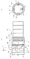
図11(A)は第4の実施の形態のテールクリアランス測定装置30の設置状態を示す説明図、(B)は(A)のBB線断面図である。
テールクリアランス測定装置30は、1台のカメラ部42と、4台の検出光投射部44と、距離検出部46(図3)と、制御盤40(図3)を備えている。
カメラ部42は、後部室12C内のテール部14寄りの箇所で後部室12Cの円形断面の中央に適宜支持部材を介してテール部14の壁部14Bに取着されている。
撮影光学系は、壁部14Bに設けられた開口12Eを介してセグメント20の端面2006の周方向の全周を撮影可能に設けられている。
4台の検出光投射部44は、後部室12C内で壁部14Bに取着されており、セグメント20の端面2006の周方向に90度の間隔をおいた4箇所に第1の検出光L1、第2の検出光L2を投射するように、テール部14の内周面1402の周方向に90度の間隔をおいて設けられている。
具体的には、鉛直方向の上下2箇所と、鉛直方向と直交する水平方向の2箇所に設けられている。
したがって、カメラ部42は、これら4箇所において、第1、第2の検出光L1、L2を含むセグメント端面領域Seの画像を撮像する。
(Fourth embodiment)
Next, a fourth embodiment will be described.
In the fourth embodiment, tail clearance is measured using a
FIG. 11A is an explanatory view showing an installation state of the tail
The tail
The
The photographing optical system is provided so as to be able to photograph the entire circumference in the circumferential direction of the
The four detection
Specifically, it is provided at two places in the vertical direction and two places in the horizontal direction perpendicular to the vertical direction.
Therefore, the
第4の実施の形態によれば、第1の実施の形態と同様の効果が奏されることは無論のこと、カメラ部42が1台で足りるためコストを削減する上で有利となり、しかも、カメラ部42が後部室12C内に占有するスペースがごく僅かなもので済み、したがって、後部室12Cにスペースの余裕がない小型のシールドマシン10にテールクリアランス測定装置30を搭載する上で有利となる。
According to the fourth embodiment, it is obvious that the same effect as that of the first embodiment can be obtained, and it is advantageous in reducing the cost because one
(第5の実施の形態)
次に第5の実施の形態について説明する。
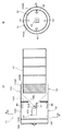
第5の実施の形態は第4の実施の形態の変形例であり、光ファイバー60を有する単一のカメラ部42を用いてテールクリアランスを測定するものである。
図12(A)は第5の実施の形態のテールクリアランス測定装置30の設置状態を示す説明図、(B)は(A)のBB線断面図である。
テールクリアランス測定装置30は、1台のカメラ部42と、4台の検出光投射部44と、距離検出部46(図3)と、制御盤40(図3)を備えている。
カメラ部42は1台設けられ、カメラ部42は、カメラ本体42Aと、光ファイバー60と、光ファイバーの先端に取着された不図示の撮影光学系とを有している。
撮影光学系は後部室12C内のテール部14寄りの箇所で後部室12Cの円形断面の中央に適宜支持部材を介して取着されており、セグメント20の端面2006の周方向の全周を撮影可能に設けられている。
カメラ本体42A(図3)は後方台車16(図1)に配置されている。
撮影光学系により撮影されたセグメント20の端面2006の周方向の全周にわたる画像は光ファイバー60を介してカメラ本体42Aに導かれる。
4台の検出光投射部44は、後部室12C内で壁部14Bに取着されており、セグメント20の端面2006の周方向に90度の間隔をおいた4箇所に第1の検出光L1、第2の検出光L2を投射するように、テール部14の内周面1402の周方向に90度の間隔をおいて設けられている。
具体的には、鉛直方向の上下2箇所と、鉛直方向と直交する水平方向の2箇所に設けられている。
したがって、カメラ部42は、これら4箇所において、第1、第2の検出光L1、L2を含むセグメント端面領域Seの画像を撮像する。
(Fifth embodiment)
Next, a fifth embodiment will be described.
The fifth embodiment is a modification of the fourth embodiment, in which tail clearance is measured using a
FIG. 12A is an explanatory view showing an installation state of the tail
The tail
One
The photographing optical system is attached to the center of the circular cross section of the
The
An image over the entire circumference in the circumferential direction of the
The four detection
Specifically, it is provided at two places in the vertical direction and two places in the horizontal direction perpendicular to the vertical direction.
Therefore, the
第5の実施の形態によれば、第1の実施の形態と同様の効果が奏されることは無論のこと、カメラ部42が1台で足りコストを削減する上で有利となる。
また、光ファイバー60を介して画像をカメラ本体42Aに導くことでカメラ本体42Aをシールドマシン10から離れた箇所に配置できるため、シールドマシン10の掘進に伴い発生する地下水などがカメラ本体42Aに直接かかることを確実に防止でき、カメラ本体42Aの保護、耐久性の向上を図る上でより一層有利となる。
また、1台のカメラ本体42Aを後部室12Cから離れた後方台車16に配置し、かつ、後部室12C内に1束の光ファイバー60とその先端に設けられた撮影光学系のみを配置したので、テールクリアランス測定装置30が後部室12C内に占有するスペースがごく僅かなもので済むため、後部室12Cにスペースの余裕がない小型のシールドマシン10にテールクリアランス測定装置30を搭載する上でより一層有利となる。
According to the fifth embodiment, it is needless to say that the same effects as those of the first embodiment can be obtained, and only one
Further, since the camera
Since one
(第6の実施の形態)
次に第6の実施の形態について説明する。
第6の実施の形態は、第4の実施の形態の変形例である。
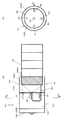
図13(A)は第6の実施の形態のテールクリアランス測定装置30の設置状態を示す説明図、(B)は(A)のBB線断面図である。
テールクリアランス測定装置30は、1台のカメラ部42と、2台の検出光投射部44と、距離検出部46(図3)と、制御盤40(図3)に加えて内径測定部62を備えている。
(Sixth embodiment)
Next, a sixth embodiment will be described.
The sixth embodiment is a modification of the fourth embodiment.
FIG. 13A is an explanatory view showing an installation state of the tail
The tail
内径測定部62はテール部14に搭載され、トンネル18(図1)に既にリング状に組み付けられたセグメント20のうち掘進方向の前端に位置するセグメント20の内径を少なくとも2箇所測定して制御盤40、通信回線36を介してコンピュータ34に供給するものである。
内径測定部62としては、従来公知のさまざまな距離センサが使用可能である。
The inner
As the inner
カメラ部42は1台設けられ、後部室12C内でテール部14の壁部14Bに取着されている。
カメラ部42は、セグメント20の端面2006の周方向の1箇所を撮影するように、テール部14の内周面1402の周方向の1箇所に設けられている。
One
The
2台の検出光投射部44は、後部室12C内で壁部14Bに取着されており、カメラ部42で撮影される撮影範囲内においてセグメント20の端面2006の周方向に間隔をおいた2箇所に第1の検出光L1、第2の検出光L2をそれぞれ投射するように、テール部14の内周面1402の周方向に間隔をおいた2箇所に設けられている。
したがって、カメラ部42は、これら2箇所において、第1、第2の検出光L1、L2を含むセグメント端面領域Seの画像を撮像する。
The two detection
Therefore, the
コンピュータ34は、各距離検出部46から得られるストローク量の測定データに基づいてセグメント20が掘進方向に対してなす傾き(傾斜角度)のデータを求める。
また、コンピュータ34は、カメラ部42から供給されるセグメント20の端面2006の周方向の1箇所の画像情報を、前記傾きのデータと、内径測定部62から供給されるセグメント20の内径の測定データとに基づいて修正した上で、テール部14のスキンプレート14Aの内周面1402とセグメント20の外周面2002とのテールクリアランスを導出する。
The
Further, the
第6の実施の形態によれば、第1の実施の形態と同様の効果が奏されることは無論のこと、1台のカメラ部42で撮影された画像情報をセグメント20の傾きのデータおよびセグメント20の内径のデータに基づいて修正することで正確なテールクリアランスを求めることができることから、カメラ部42が1台で足りるためコストを削減する上で有利となり、しかも、カメラ部42が後部室12C内に占有するスペースがごく僅かなもので済み、したがって、後部室12Cにスペースの余裕がない小型のシールドマシン10にテールクリアランス測定装置30を搭載する上で有利となる。
Of course, according to the sixth embodiment, the same effect as the first embodiment can be obtained, and the image information captured by one
(第7の実施の形態)
次に第7の実施の形態について説明する。
第7の実施の形態は、第6の実施の形態の変形例であり、光ファイバー60を有する単一のカメラ部42を用いてテールクリアランスを測定するものである。
図14(A)は第7の実施の形態のテールクリアランス測定装置30の設置状態を示す説明図、(B)は(A)のBB線断面図である。
(Seventh embodiment)
Next, a seventh embodiment will be described.
The seventh embodiment is a modification of the sixth embodiment, and measures the tail clearance using a
FIG. 14A is an explanatory view showing an installation state of the tail
カメラ部42は1台設けられ、カメラ部42は、カメラ本体42Aと、光ファイバー60と、光ファイバーの先端に取着された不図示の撮影光学系とを有している。
撮影光学系は後部室12C内でテール部14の壁部14Bに取着されており、セグメント20の端面2006の周方向の1箇所を撮影するように、テール部14の内周面1402の周方向の1箇所に設けられている。
カメラ本体42Aは後方台車16(台車16A)に配置されている。
撮影光学系により撮影されたセグメント20の端面2006の周方向の1箇所の画像は光ファイバー60を介してカメラ本体42Aに導かれる。
One
The photographing optical system is attached to the
The
One image in the circumferential direction of the
2台の検出光投射部44は、後部室12C内で壁部14Bに取着されており、前記撮影光学系で撮影される撮影範囲内においてセグメント20の端面2006の周方向に間隔をおいた2箇所に第1の検出光L1、第2の検出光L2をそれぞれ投射するように、テール部14の内周面1402の周方向に間隔をおいた2箇所に設けられている。
したがって、カメラ部42は、これら2箇所において、第1、第2の検出光L1、L2を含むセグメント端面領域Seの画像を撮像する。
The two detection
Therefore, the
内径測定部62は、第6の実施の形態と同様にテール部14に搭載され、トンネル18(図1)に既にリング状に組み付けられたセグメント20のうち掘進方向の前端に位置するセグメント20の内径を少なくとも2箇所測定してコンピュータ34に供給する。
The inner
コンピュータ34は、各距離検出部46から得られるストローク量の測定データに基づいてセグメント20が掘進方向に対してなす傾き(傾斜角度)のデータを求める。
また、コンピュータ34は、カメラ部42から供給されるセグメント20の端面2006の周方向の1箇所の画像情報を、前記傾きのデータと、内径測定部62から供給されるセグメント20の内径の測定データとに基づいて修正した上で、テール部14のスキンプレート14Aの内周面1402とセグメント20の外周面2002とのテールクリアランスを導出する。
The
Further, the
第7の実施の形態によれば、第1の実施の形態と同様の効果が奏されることは無論のこと、1台のカメラ部42で撮影された画像情報をセグメント20の傾きのデータおよびセグメント20の内径のデータに基づいて修正することで正確なテールクリアランスを求めることができることから、カメラ部42が1台で足りるためコストを削減する上で有利となる。
また、光ファイバー60を介して画像をカメラ本体42Aに導くことでカメラ本体42Aをシールドマシン10から離れた箇所に配置できるため、シールドマシン10の掘進に伴い発生する地下水などがカメラ本体42Aに直接かかることを確実に防止でき、カメラ本体42Aの保護、耐久性の向上を図る上でより一層有利となる。
また、1台のカメラ本体42Aを後部室12Cから離れた後方台車16に配置し、かつ、後部室12C内に1束の光ファイバー60とその先端に設けられた撮影光学系のみを配置したので、テールクリアランス測定装置30が後部室12C内に占有するスペースがごく僅かなもので済むため、後部室12Cにスペースの余裕がない小型のシールドマシン10にテールクリアランス測定装置30を搭載する上でより一層有利となる。
Of course, according to the seventh embodiment, the same effects as those of the first embodiment can be obtained, and the image information captured by one
Further, since the camera
Since one
なお、第6、第7の実施の形態では、2台の検出光投射部44を設け、カメラ部42あるいは撮影光学系で撮影される撮影範囲内においてセグメント20の端面2006の周方向に間隔をおいた2箇所に第1の検出光L1、第2の検出光L2をそれぞれ投射するようにした。
しかしながら、3台以上の検出光投射部44を設け、カメラ部42あるいは撮影光学系で撮影される撮影範囲内においてセグメント20の端面2006の周方向に間隔をおいた3箇所以上の箇所に第1の検出光L1、第2の検出光L2をそれぞれ投射するようにしてもよい。
あるいは、1台の検出光投射部44からカメラ部42あるいは撮影光学系で撮影される撮影範囲内においてセグメント20の端面2006の周方向に間隔をおいた2箇所以上の箇所に第1の検出光L1、第2の検出光L2をそれぞれ投射するようにしてもよい。
In the sixth and seventh embodiments, two detection
However, three or more detection
Alternatively, the first detection light may be generated at two or more locations spaced from each other in the circumferential direction of the
なお、上述した各実施の形態では、クリアランス導出部が第2の検出光L2を用いて内周面側交点P1を特定するようにしたが、クリアランス導出部に対して内周面側交点P1を手作業により指定するようにすれば、第1の検出光L1のみで足り、第2の検出光L2を省いてもよい。 In each of the above-described embodiments, the clearance deriving unit specifies the inner circumferential surface side intersection P1 using the second detection light L2, but the inner circumferential surface side intersection P1 is set to the clearance deriving unit. If it is specified manually, only the first detection light L1 is sufficient, and the second detection light L2 may be omitted.
また、上述した各実施の形態では、クリアランス導出部が内周面側交点P1の変位量に基づいてテールクリアランスTcを導出する場合について説明したが、外周面側交点P2の変位量に基づいてテールクリアランスTcを導出してもよい。この場合、外周面側交点P2が特許請求の範囲の第1の交点となり、内周面側交点P1が特許請求の範囲の第2の交点となる。
そして、この場合には、検出光投射部44は、セグメント20の端面2006上でセグメント20の半径方向を延在するセグメント端面領域Seとセグメント20の外周面2002とが交わる円弧部分C2に交差する第1の検出光L1をセグメント端面領域Seに投射すればよい。
このような構成においても各実施の形態と同様の効果が奏されることは無論のことである。
In each of the above-described embodiments, the case where the clearance deriving unit derives the tail clearance Tc based on the displacement amount of the inner circumferential surface side intersection P1 has been described. However, the tail is derived based on the displacement amount of the outer circumferential surface side intersection P2. The clearance Tc may be derived. In this case, the outer peripheral surface side intersection point P2 becomes the first intersection point in the claims, and the inner peripheral surface side intersection point P1 becomes the second intersection point in the claims.
In this case, the detection
Of course, the same effects as those of the respective embodiments can be obtained even in such a configuration.
10シールドマシン
12前胴部
1202カッター
14テール部
1402内周面
16後方台車
20セグメント
2002外周面
2004内周面
2006端面
30テールクリアランス測定装置
42カメラ部
42Aカメラ本体
44検出光投射部
46距離検出部
60光ファイバー
62内径測定部
Seセグメント端面領域
C1第1の円弧部分
C2第2の円弧部分
L1第1の検出光
L2第2の検出光
P1内周面側交点(第1の交点)
P2外周面側交点(第2の交点)
Tcテールクリアランス
Tc0初期テールクリアランス
10
P2 outer peripheral surface side intersection (second intersection)
Tc tail clearance Tc0 initial tail clearance
Claims (8)
前記テール部で支持され、前記セグメントの端面上で前記セグメントの半径方向に延在するセグメント端面領域と前記セグメントの内周面または外周面の一方とが交わる円弧部分に交差し前記端面上を延在する線状の第1の検出光を前記セグメント端面領域に投射する検出光投射部と、
少なくとも撮影光学系が前記テール部で支持され、前記第1の検出光を含む前記セグメント端面領域を撮影して画像情報を生成するカメラ部と、
前記画像情報に基づいて前記テール部の内周面と前記セグメントの外周面とのクリアランスを導出するクリアランス導出部と、
を備え、
前記第1の検出光に対して前記円弧部分が交差する交点を第1の交点とした場合、
前記クリアランス導出部による前記クリアランスの導出は、予め前記シールドマシンによる掘削を開始する前に手作業により実測された前記テール部の内周面と前記セグメントの外周面との初期テールクリアランスと、前記第1の交点の変位量とに基づいてなされ、
前記第1の検出光に対して前記セグメント端面領域と前記セグメントの内周面または外周面の他方とが交わる円弧部分が交差する交点を第2の交点とした場合、
前記検出光投射部は、前記セグメント端面領域に前記第1の検出光に加え、前記第1の検出光に直交する方向に延在する第2の検出光を投射し、
前記クリアランス導出部は、前記第2の検出光に対する前記第1の交点の位置と前記第2の交点との位置とが異なることに基づいて前記第1の交点を特定する、
ことを特徴とするテールクリアランス測定装置。 A tail clearance measuring device for measuring a clearance between an inner peripheral surface of a tail portion of a shield machine and an outer peripheral surface of a segment located inside the inner peripheral surface,
The segment is supported by the tail portion and extends on the end surface crossing an arc portion where the segment end surface region extending in the radial direction of the segment on the end surface of the segment intersects one of the inner peripheral surface or the outer peripheral surface of the segment. A detection light projection unit that projects the existing linear first detection light onto the segment end face region;
A camera unit that captures at least an imaging optical system supported by the tail unit and generates image information by imaging the segment end face region including the first detection light;
A clearance deriving portion for deriving a clearance between the inner peripheral surface of the tail portion and the outer peripheral surface of the segment based on the image information;
Equipped with a,
When the intersection at which the arc portion intersects the first detection light is the first intersection,
The clearance derivation by the clearance derivation unit is performed by the initial tail clearance between the inner peripheral surface of the tail portion and the outer peripheral surface of the segment, which is manually measured before starting excavation by the shield machine in advance. Based on the displacement of the intersection of 1 and
When the intersection point where the arc portion where the segment end face region and the other one of the inner peripheral surface or the outer peripheral surface of the segment intersect with respect to the first detection light is a second intersection point,
The detection light projecting unit projects second detection light extending in a direction orthogonal to the first detection light in addition to the first detection light to the segment end face region,
The clearance deriving unit identifies the first intersection point based on a difference between a position of the first intersection point with respect to the second detection light and a position of the second intersection point;
A tail clearance measuring device characterized by that.
ことを特徴とする請求項1記載のテールクリアランス測定装置。 A plurality of the imaging optical system and the detection light projection unit are provided at intervals in the circumferential direction of the tail unit,
The tail clearance measuring device according to claim 1 .
前記テール部は、前記前胴部の後端に屈曲可能に結合され、
前記カメラ部は、被写体像を撮像する撮像素子を含むカメラ本体と、先端に前記撮影光学系が取着され前記被写体像を前記撮像素子に導く光ファイバーとを含み、
前記カメラ本体は前記前胴部に配置されている、
ことを特徴とする請求項1または2記載のテールクリアランス測定装置。 The shield machine has a front trunk portion in which a cutter is disposed at the front portion,
The tail portion is flexibly coupled to a rear end of the front body portion,
The camera unit includes a camera body including an image pickup device that picks up a subject image, and an optical fiber that attaches the photographing optical system to a tip and guides the subject image to the image pickup device,
The camera body is disposed on the front torso,
The tail clearance measuring device according to claim 1 or 2 , characterized in that
前記テール部は、前記前胴部の後端に屈曲可能に結合され、
前記テール部で組み立てられたセグメントトンネル内に後方台車が設けられ、
前記カメラ部は、被写体像を撮像する撮像素子を含むカメラ本体と、先端に前記撮影光学系が取着され前記被写体像を前記撮像素子に導く光ファイバーとを含み、
前記カメラ本体は前記後方台車に配置されている、
ことを特徴とする請求項1または2記載のテールクリアランス測定装置。 The shield machine has a front trunk portion in which a cutter is disposed at the front portion,
The tail portion is flexibly coupled to a rear end of the front body portion,
A rear carriage is provided in the segment tunnel assembled by the tail part,
The camera unit includes a camera body including an image pickup device that picks up a subject image, and an optical fiber that attaches the photographing optical system to a tip and guides the subject image to the image pickup device,
The camera body is disposed on the rear carriage,
The tail clearance measuring device according to claim 1 or 2 , characterized in that
前記テール部は、前記前胴部の後端に屈曲可能に結合され、
前記前胴部に前記セグメントを掘進方向と反対方向に押圧する複数のジャッキ装置が設けられ、
前記カメラ部は、前記セグメントの端面の周方向の全周にわたって撮影するように1台設けられ、
前記カメラ部は前記テール部に取着され、
前記複数のジャッキ装置の少なくとも2台のジャッキ装置が前記セグメントを掘進方向と反対方向に押圧する際のストローク量を測定し、その測定データを前記クリアランス導出部に供給する距離検出部を設け、
前記クリアランス導出部による前記クリアランスの導出は、前記画像情報を前記ストローク量の測定データに基づいて修正することによってなされる、
ことを特徴とする請求項1または2記載のテールクリアランス測定装置。 The shield machine has a front trunk portion in which a cutter is disposed at the front portion,
The tail portion is flexibly coupled to a rear end of the front body portion,
A plurality of jack devices for pressing the segment in the direction opposite to the digging direction are provided on the front body portion,
One camera part is provided so as to shoot over the entire circumference in the circumferential direction of the end face of the segment,
The camera part is attached to the tail part,
A distance detecting unit for measuring a stroke amount when at least two jack devices of the plurality of jack devices press the segment in a direction opposite to the digging direction, and supplying the measurement data to the clearance deriving unit;
Derivation of the clearance by the clearance deriving unit is performed by correcting the image information based on the measurement data of the stroke amount.
The tail clearance measuring device according to claim 1 or 2 , characterized in that
前記テール部は、前記前胴部の後端に屈曲可能に結合され、
前記テール部で組み立てられたセグメントトンネル内に後方台車が設けられ、
前記前胴部に前記セグメントを掘進方向と反対方向に押圧する複数のジャッキ装置が設けられ、
前記カメラ部は、被写体像を撮像する撮像素子を含む1台のカメラ本体と、先端に前記撮影光学系が取着され前記被写体像を前記撮像素子に導く1束の光ファイバーとを含み、
前記カメラ本体は前記後方台車に配置され、
前記撮影光学系は、前記セグメントの端面の周方向の全周にわたって撮影するように設けられ、
前記複数のジャッキ装置の少なくとも2台のジャッキ装置が前記セグメントを掘進方向と反対方向に押圧する際のストローク量を測定し、その測定データを前記クリアランス導出部に供給する距離検出部を設け、
前記クリアランス導出部による前記クリアランスの導出は、前記画像情報を前記ストローク量の測定データに基づいて修正することによってなされる、
ことを特徴とする請求項1または2記載のテールクリアランス測定装置。 The shield machine has a front trunk portion in which a cutter is disposed at the front portion,
The tail portion is flexibly coupled to a rear end of the front body portion,
A rear carriage is provided in the segment tunnel assembled by the tail part,
A plurality of jack devices for pressing the segment in the direction opposite to the digging direction are provided on the front body portion,
The camera unit includes one camera body including an image pickup device that picks up a subject image, and a bundle of optical fibers that are attached to the tip of the image pickup optical system and guide the subject image to the image pickup device.
The camera body is disposed on the rear carriage,
The photographing optical system is provided so as to photograph over the entire circumference in the circumferential direction of the end face of the segment,
A distance detecting unit for measuring a stroke amount when at least two jack devices of the plurality of jack devices press the segment in a direction opposite to the digging direction, and supplying the measurement data to the clearance deriving unit;
Derivation of the clearance by the clearance deriving unit is performed by correcting the image information based on the measurement data of the stroke amount.
The tail clearance measuring device according to claim 1 or 2 , characterized in that
前記テール部は、前記前胴部の後端に屈曲可能に結合され、
前記前胴部に前記セグメントを掘進方向と反対方向に押圧する複数のジャッキ装置が設けられ、
前記カメラ部は、前記セグメントの端面の周方向の1箇所を撮影するように1台設けられ、
前記カメラ部は前記テール部に取着され、
前記検出光投射部は、前記カメラ部で撮影される撮影範囲内において前記セグメントの周方向に間隔をおいた少なくとも2箇所に前記第1の検出光を投射するように構成され、
前記複数のジャッキ装置の少なくとも2台のジャッキ装置が前記セグメントを掘進方向と反対方向に押圧する際のストローク量を測定し、その測定データを前記クリアランス導出部に供給する距離検出部を設け、
既にリング状に組み付けられたセグメントのうち掘進方向の前端に位置するセグメントの内径を少なくとも2箇所を測定して、内径の測定データを前記クリアランス導出部に供給する内径測定部を設け、
前記クリアランス導出部による前記クリアランスの導出は、前記画像情報を前記ストローク量の測定データおよび前記セグメントの内径の測定データに基づいて修正することによってなされる、
ことを特徴とする請求項1または2記載のテールクリアランス測定装置。 The shield machine has a front trunk portion in which a cutter is disposed at the front portion,
The tail portion is flexibly coupled to a rear end of the front body portion,
A plurality of jack devices for pressing the segment in the direction opposite to the digging direction are provided on the front body portion,
One camera part is provided so as to photograph one place in the circumferential direction of the end face of the segment,
The camera part is attached to the tail part,
The detection light projection unit is configured to project the first detection light to at least two places spaced in the circumferential direction of the segment within a photographing range photographed by the camera unit,
A distance detecting unit for measuring a stroke amount when at least two jack devices of the plurality of jack devices press the segment in a direction opposite to the digging direction, and supplying the measurement data to the clearance deriving unit;
Measuring at least two inner diameters of the segments located at the front end in the direction of digging among the segments already assembled in a ring shape, and providing an inner diameter measuring section for supplying inner diameter measurement data to the clearance deriving section;
Derivation of the clearance by the clearance deriving unit is performed by correcting the image information based on the measurement data of the stroke amount and the measurement data of the inner diameter of the segment.
The tail clearance measuring device according to claim 1 or 2 , characterized in that
前記テール部は、前記前胴部の後端に屈曲可能に結合され、
前記テール部で組み立てられたセグメントトンネル内に後方台車が設けられ、
前記前胴部に前記セグメントを掘進方向と反対方向に押圧する複数のジャッキ装置が設けられ、
前記カメラ部は、被写体像を撮像する撮像素子を含む1台のカメラ本体と、先端に前記撮影光学系が取着され前記被写体像を前記撮像素子に導く1束の光ファイバーとを含み、
前記カメラ本体は前記後方台車に配置され、
前記撮影光学系は、前記セグメントの端面の周方向の1箇所を撮影するように設けられ、
前記検出光投射部は、前記撮影光学系で撮影される撮影範囲内において前記セグメントの周方向に間隔をおいた少なくとも2箇所に前記第1の検出光を投射するように構成され、
前記複数のジャッキ装置の少なくとも2台のジャッキ装置が前記セグメントを掘進方向と反対方向に押圧する際のストローク量を測定し、その測定データを前記クリアランス導出部に供給する距離検出部を設け、
既にリング状に組み付けられたセグメントのうち掘進方向の前端に位置するセグメントの内径を少なくとも2箇所を測定して、内径の測定データを前記クリアランス導出部に供給する内径測定部を設け、
前記クリアランス導出部による前記クリアランスの導出は、前記画像情報を前記ストローク量の測定データおよび前記セグメントの内径の測定データに基づいて修正することによってなされる、
ことを特徴とする請求項1または2記載のテールクリアランス測定装置。 The shield machine has a front trunk portion in which a cutter is disposed at the front portion,
The tail portion is flexibly coupled to a rear end of the front body portion,
A rear carriage is provided in the segment tunnel assembled by the tail part,
A plurality of jack devices for pressing the segment in the direction opposite to the digging direction are provided on the front body portion,
The camera unit includes one camera body including an image pickup device that picks up a subject image, and a bundle of optical fibers that are attached to the tip of the image pickup optical system and guide the subject image to the image pickup device.
The camera body is disposed on the rear carriage,
The photographing optical system is provided so as to photograph one place in the circumferential direction of the end face of the segment,
The detection light projection unit is configured to project the first detection light to at least two places spaced in the circumferential direction of the segment within a photographing range photographed by the photographing optical system,
A distance detecting unit for measuring a stroke amount when at least two jack devices of the plurality of jack devices press the segment in a direction opposite to the digging direction, and supplying the measurement data to the clearance deriving unit;
Measuring at least two inner diameters of the segments located at the front end in the direction of digging among the segments already assembled in a ring shape, and providing an inner diameter measuring section for supplying inner diameter measurement data to the clearance deriving section;
Derivation of the clearance by the clearance deriving unit is performed by correcting the image information based on the measurement data of the stroke amount and the measurement data of the inner diameter of the segment.
The tail clearance measuring device according to claim 1 or 2 , characterized in that
Priority Applications (1)
| Application Number | Priority Date | Filing Date | Title |
|---|---|---|---|
| JP2014202843A JP6482811B2 (en) | 2014-10-01 | 2014-10-01 | Tail clearance measuring device |
Applications Claiming Priority (1)
| Application Number | Priority Date | Filing Date | Title |
|---|---|---|---|
| JP2014202843A JP6482811B2 (en) | 2014-10-01 | 2014-10-01 | Tail clearance measuring device |
Publications (2)
| Publication Number | Publication Date |
|---|---|
| JP2016070013A JP2016070013A (en) | 2016-05-09 |
| JP6482811B2 true JP6482811B2 (en) | 2019-03-13 |
Family
ID=55866355
Family Applications (1)
| Application Number | Title | Priority Date | Filing Date |
|---|---|---|---|
| JP2014202843A Active JP6482811B2 (en) | 2014-10-01 | 2014-10-01 | Tail clearance measuring device |
Country Status (1)
| Country | Link |
|---|---|
| JP (1) | JP6482811B2 (en) |
Families Citing this family (4)
| Publication number | Priority date | Publication date | Assignee | Title |
|---|---|---|---|---|
| JP7156894B2 (en) * | 2018-10-04 | 2022-10-19 | 株式会社フジタ | Roundness measuring device |
| CN111457851B (en) * | 2020-04-14 | 2021-11-23 | 中国铁建重工集团股份有限公司 | Shield tail clearance measurement system and method for shield machine |
| CN112945115B (en) * | 2021-02-04 | 2022-09-09 | 中铁工程装备集团有限公司 | Shield tail gap vision measurement method and device based on double laser structure lines |
| CN113358046B (en) * | 2021-05-19 | 2023-04-14 | 上海隧道工程有限公司 | Visual measurement method and system for shield tail clearance |
Family Cites Families (7)
| Publication number | Priority date | Publication date | Assignee | Title |
|---|---|---|---|---|
| JPS63315797A (en) * | 1987-06-17 | 1988-12-23 | 鹿島建設株式会社 | Method of measuring tail clearance of shielding machine |
| JP2651346B2 (en) * | 1993-08-23 | 1997-09-10 | 鹿島建設株式会社 | Tail clearance measurement method and device |
| JPH11280378A (en) * | 1998-03-31 | 1999-10-12 | Hitachi Zosen Corp | Method and device for measuring clearance of tail section in shield machine |
| JP5139740B2 (en) * | 2007-07-23 | 2013-02-06 | 大成建設株式会社 | Tail clearance automatic measurement system and tail clearance automatic measurement method |
| JP5179842B2 (en) * | 2007-11-15 | 2013-04-10 | 株式会社フジタ | Tail clearance measuring device |
| JP5476008B2 (en) * | 2009-02-18 | 2014-04-23 | 株式会社フジタ | Tail clearance measuring device |
| CN102721381A (en) * | 2012-06-21 | 2012-10-10 | 三一重工股份有限公司 | Shield tail clearance detecting and displaying system as well as method and shield machine thereof |
-
2014
- 2014-10-01 JP JP2014202843A patent/JP6482811B2/en active Active
Also Published As
| Publication number | Publication date |
|---|---|
| JP2016070013A (en) | 2016-05-09 |
Similar Documents
| Publication | Publication Date | Title |
|---|---|---|
| JP5476008B2 (en) | Tail clearance measuring device | |
| JP6482811B2 (en) | Tail clearance measuring device | |
| JP2007249722A (en) | Object detector | |
| US9667923B2 (en) | Camera attitude detection device and work region line display device | |
| JP4630137B2 (en) | Object monitoring system, object monitoring method, and object monitoring program | |
| WO2015198410A1 (en) | Outside recognition device | |
| CN104749578A (en) | Surveying Instrument | |
| JP2012533749A (en) | Equipment for optical scanning and measurement of surroundings | |
| CN112556592B (en) | Shield tail clearance measurement system and method based on visual positioning | |
| JP2016027372A (en) | Borescope and navigation method thereof | |
| JP6097063B2 (en) | Height measuring device and height measuring method | |
| JP5179842B2 (en) | Tail clearance measuring device | |
| JP5139740B2 (en) | Tail clearance automatic measurement system and tail clearance automatic measurement method | |
| JP2014029113A (en) | Device, method, program and record medium for identifying tail clearance | |
| JP7156894B2 (en) | Roundness measuring device | |
| CN111526337B (en) | Early warning system and early warning method for engineering machinery and engineering machinery | |
| KR101944817B1 (en) | Detection Automatic System of Excavating Work Using Mobile Terminal | |
| JP5485325B2 (en) | Tail clearance measuring device | |
| KR101497396B1 (en) | A system for measuring target location and method for measuring target location using the same | |
| JP6867089B2 (en) | Object detection system | |
| JP4240369B2 (en) | Hole wall development image generation method and apparatus | |
| JP2017025503A (en) | Assisting display system for construction equipment operation | |
| JP2020045682A (en) | Excavator position measurement system and operation analysis system | |
| JP7292344B2 (en) | Welding system, welding method and program | |
| JP6143330B2 (en) | Roundness measuring device and roundness measuring method |
Legal Events
| Date | Code | Title | Description |
|---|---|---|---|
| A621 | Written request for application examination |
Free format text: JAPANESE INTERMEDIATE CODE: A621 Effective date: 20170926 |
|
| A977 | Report on retrieval |
Free format text: JAPANESE INTERMEDIATE CODE: A971007 Effective date: 20180613 |
|
| A131 | Notification of reasons for refusal |
Free format text: JAPANESE INTERMEDIATE CODE: A131 Effective date: 20180710 |
|
| A521 | Request for written amendment filed |
Free format text: JAPANESE INTERMEDIATE CODE: A523 Effective date: 20180820 |
|
| TRDD | Decision of grant or rejection written | ||
| A01 | Written decision to grant a patent or to grant a registration (utility model) |
Free format text: JAPANESE INTERMEDIATE CODE: A01 Effective date: 20190205 |
|
| A61 | First payment of annual fees (during grant procedure) |
Free format text: JAPANESE INTERMEDIATE CODE: A61 Effective date: 20190213 |
|
| R150 | Certificate of patent or registration of utility model |
Ref document number: 6482811 Country of ref document: JP Free format text: JAPANESE INTERMEDIATE CODE: R150 |
|
| R250 | Receipt of annual fees |
Free format text: JAPANESE INTERMEDIATE CODE: R250 |
|
| R250 | Receipt of annual fees |
Free format text: JAPANESE INTERMEDIATE CODE: R250 |
|
| R250 | Receipt of annual fees |
Free format text: JAPANESE INTERMEDIATE CODE: R250 |