JP6478024B2 - Vehicle travel control device - Google Patents
Vehicle travel control device Download PDFInfo
- Publication number
- JP6478024B2 JP6478024B2 JP2014257548A JP2014257548A JP6478024B2 JP 6478024 B2 JP6478024 B2 JP 6478024B2 JP 2014257548 A JP2014257548 A JP 2014257548A JP 2014257548 A JP2014257548 A JP 2014257548A JP 6478024 B2 JP6478024 B2 JP 6478024B2
- Authority
- JP
- Japan
- Prior art keywords
- vehicle
- inertial
- speed
- engine
- detecting
- Prior art date
- Legal status (The legal status is an assumption and is not a legal conclusion. Google has not performed a legal analysis and makes no representation as to the accuracy of the status listed.)
- Active
Links
Images
Classifications
-
- Y—GENERAL TAGGING OF NEW TECHNOLOGICAL DEVELOPMENTS; GENERAL TAGGING OF CROSS-SECTIONAL TECHNOLOGIES SPANNING OVER SEVERAL SECTIONS OF THE IPC; TECHNICAL SUBJECTS COVERED BY FORMER USPC CROSS-REFERENCE ART COLLECTIONS [XRACs] AND DIGESTS
- Y02—TECHNOLOGIES OR APPLICATIONS FOR MITIGATION OR ADAPTATION AGAINST CLIMATE CHANGE
- Y02T—CLIMATE CHANGE MITIGATION TECHNOLOGIES RELATED TO TRANSPORTATION
- Y02T10/00—Road transport of goods or passengers
- Y02T10/10—Internal combustion engine [ICE] based vehicles
- Y02T10/40—Engine management systems
-
- Y—GENERAL TAGGING OF NEW TECHNOLOGICAL DEVELOPMENTS; GENERAL TAGGING OF CROSS-SECTIONAL TECHNOLOGIES SPANNING OVER SEVERAL SECTIONS OF THE IPC; TECHNICAL SUBJECTS COVERED BY FORMER USPC CROSS-REFERENCE ART COLLECTIONS [XRACs] AND DIGESTS
- Y02—TECHNOLOGIES OR APPLICATIONS FOR MITIGATION OR ADAPTATION AGAINST CLIMATE CHANGE
- Y02T—CLIMATE CHANGE MITIGATION TECHNOLOGIES RELATED TO TRANSPORTATION
- Y02T10/00—Road transport of goods or passengers
- Y02T10/60—Other road transportation technologies with climate change mitigation effect
Description
本発明は、車両の走行制御装置に係り、詳しくはオートクルーズ制御中の惰性走行制御に関する。 The present invention relates to a vehicle travel control device, and more particularly to inertial travel control during auto-cruise control.
近年、運転者が設定した目標車速を維持するように車両の駆動力を調整するオートクルーズ制御を実行可能な車両が開発されている。 In recent years, vehicles capable of executing auto-cruise control that adjusts the driving force of the vehicle so as to maintain the target vehicle speed set by the driver have been developed.
例えばオートクルーズ制御可能なハイブリッド車両において、車両の減速時にエンジンへの燃料供給を停止することで燃費向上を図る技術が開示されている(特許文献1参照)。 For example, in a hybrid vehicle capable of auto-cruise control, a technique for improving fuel consumption by stopping fuel supply to an engine when the vehicle decelerates is disclosed (see Patent Document 1).
特許文献1のようにエンジンへの燃料供給を停止すると、エンジンのフリクションによる制動力(エンジンブレーキ)が生じ、必要以上に速度が低下して速度復帰のために再加速を行う等して燃費が悪化する場合がある。 When the fuel supply to the engine is stopped as in Patent Document 1, a braking force (engine brake) due to engine friction is generated, the speed is reduced more than necessary, and the fuel is re-accelerated for speed recovery. It may get worse.
これに対し、クラッチを切断状態又は変速機のギヤをニュートラル状態として、エンジンのフリクションを駆動系から切り離した惰性走行を行うことで、走行の負荷を低減し、エンジンブレーキによる不要な減速を回避して燃費の向上を図ることができる。 In contrast, coasting with the clutch disengaged or the transmission gear in the neutral state and the engine friction separated from the drive system reduces the driving load and avoids unnecessary deceleration due to engine braking. This can improve fuel efficiency.
しかし、オートクルーズ制御中に降坂路等で惰性走行を行うと車速が目標車速よりも増速してしまい、不要な減速を行う必要が生じて却って燃費が悪化するおそれがある。 However, if coasting is performed on a downhill road or the like during auto-cruise control, the vehicle speed increases beyond the target vehicle speed, and there is a possibility that unnecessary deceleration must be performed, resulting in a deterioration in fuel consumption.
本発明はこのような問題を解決するためになされたもので、その目的とするところは、オートクルーズ制御中に目標車速を維持するのに影響の少ない状況で適切に惰性走行を行うことで、燃費を向上させることのできる車両の走行制御装置を提供することにある。 The present invention was made to solve such a problem, and the object of the present invention is to appropriately perform inertial running in a situation that has little influence on maintaining the target vehicle speed during auto-cruise control, An object of the present invention is to provide a vehicle travel control device that can improve fuel consumption.
本発明は前述の課題の少なくとも一部を解決するためになされたものであり、以下の態様又は適用例として実現することができる。 SUMMARY An advantage of some aspects of the invention is to solve at least a part of the problems described above, and the invention can be implemented as the following aspects or application examples.
(1)本適用例に係る車両の走行制御装置は、車両の駆動源であるエンジンがクラッチを介して自動変速機と接続されている車両の走行制御装置であって、少なくとも自動変速により駆動を行うDレンジを含むシフト位置の中から1つのシフト位置を選択するシフトレバーと、運転者により設定された目標車速を維持するように前記車両の駆動力を調整するオートクルーズ制御を行うオートクルーズ制御手段と、前記車両の車速を検出する車速検出手段と、前記エンジンが稼働状態であり、前記シフトレバーにより選択されるシフト位置がDレンジであり、アクセルペダル及びブレーキペダルの踏み込みがなく、前記オートクルーズ制御手段によるオートクルーズ制御中であり、前記車速検出手段によって検出された前記車両の車速が前記目標車速に対して所定の許容速度範囲にあり、前記エンジンのエンジントルクが所定のトルク範囲内であるという惰性走行開始条件が成立したときに、前記クラッチの切断状態及び前記自動変速機のギヤのニュートラル状態の少なくともいずれかの状態とすることで惰性走行を実行する惰性走行制御手段と、を備える。 (1) A vehicle travel control apparatus according to this application example is a vehicle travel control apparatus in which an engine that is a vehicle drive source is connected to an automatic transmission via a clutch, and is driven at least by automatic transmission. A shift lever for selecting one shift position from among shift positions including the D range to be performed, and auto cruise control for performing auto cruise control for adjusting the driving force of the vehicle so as to maintain the target vehicle speed set by the driver Means, vehicle speed detecting means for detecting the vehicle speed of the vehicle, the engine is in an operating state, the shift position selected by the shift lever is in the D range, the accelerator pedal and the brake pedal are not depressed, and the auto is under the auto-cruise control by the cruise control means, speed of the vehicle detected by said vehicle speed detecting means is the eye When the inertial running start condition that the engine speed is within a predetermined allowable speed range with respect to the vehicle speed and the engine torque of the engine is within the predetermined torque range is satisfied, the clutch disengaged state and the neutral of the gear of the automatic transmission And inertia running control means for executing inertia running by setting at least one of the states.
(2)本適用例に係る車両の走行制御装置は、上記(1)において、前記惰性走行制御手段による前記惰性走行のオン、オフを切り替え可能な惰性走行スイッチと、前記ブレーキペダルの操作に応じた制動以外で制動力を生じさせる補助ブレーキ手段と、前記補助ブレーキ手段のオン、オフを切り替え可能な補助ブレーキスイッチとを備え、前記惰性走行制御手段は、前記惰性走行開始条件に加えて、前記惰性走行スイッチがオンであり、前記補助ブレーキスイッチがオフであることを条件に前記惰性走行を実行してもよい。 (2) The vehicle travel control device according to the application example described above in (1), in accordance with an operation of the inertial travel switch that can switch on / off the inertial travel by the inertial travel control means, and the operation of the brake pedal Auxiliary braking means for generating a braking force other than braking, and an auxiliary brake switch capable of switching on and off of the auxiliary braking means, and the inertial traveling control means includes the inertial traveling start condition, The inertial traveling may be executed on condition that the inertial traveling switch is on and the auxiliary brake switch is off.
(3)本適用例に係る車両の走行制御装置は、上記(1)又は(2)において、前記惰性走行制御手段は、前記条件に加えて、前記自動変速機の変速段が所定段以上であることを条件に前記惰性走行を実行してもよい。 (3) In the vehicle travel control device according to this application example, in the above (1) or (2), the inertial travel control means may be configured such that, in addition to the above conditions, the shift stage of the automatic transmission is greater than or equal to a predetermined stage. The inertial running may be executed on the condition that it exists.
(4)本適用例に係る車両の走行制御装置は、上記(1)から(3)のいずれかにおいて、前記車両が走行している路面の勾配を検出する路面勾配検出手段を備え、前記惰性走行制御手段は、前記条件に加えて、前記路面勾配検出手段により検出される路面勾配が所定の勾配範囲内にあることを条件に前記惰性走行を実行してもよい。 (4) The vehicle travel control device according to this application example includes a road surface gradient detection unit that detects a gradient of a road surface on which the vehicle is traveling in any one of the above (1) to (3), and the inertia The traveling control means may execute the inertia traveling on the condition that the road surface gradient detected by the road surface gradient detecting means is within a predetermined gradient range in addition to the conditions.
(5)本適用例に係る車両の走行制御装置は、上記(1)から(4)のいずれかにおいて、前記車両のエンジン回転数を検出するエンジン回転数検出手段を備え、前記惰性走行制御手段は、前記条件に加えて、前記エンジン回転数検出手段により検出されるエンジン回転数が所定回転数以下であることを条件に前記惰性走行を実行してもよい。 (5) The vehicle travel control apparatus according to this application example includes the engine speed detection means for detecting the engine speed of the vehicle according to any one of (1) to (4), and the inertial travel control means. In addition to the above conditions, the inertial running may be executed on condition that the engine speed detected by the engine speed detecting means is not more than a predetermined speed.
(6)本適用例に係る車両の走行制御装置は、上記(1)から(5)のいずれかにおいて、前記車両の加速度を検出する加速度検出手段を備え、前記惰性走行制御手段は、前記条件に加えて、前記加速度検出手段により検出される加速度が所定の加速度範囲内であることを条件に前記惰性走行を実行してもよい。 ( 6 ) The vehicle travel control apparatus according to this application example includes the acceleration detection means for detecting the acceleration of the vehicle according to any one of (1) to ( 5 ), wherein the inertial travel control means includes the condition In addition, the inertial running may be executed on condition that the acceleration detected by the acceleration detecting means is within a predetermined acceleration range.
(7)本適用例に係る車両の走行制御装置は、上記(1)から(6)のいずれかにおいて、前記惰性走行制御手段は、前記惰性走行を実行中に前記アクセルペダル及び前記ブレーキペダルのいずれかが踏み込まれたときには、前記惰性走行を終了してもよい。 ( 7 ) In the vehicle travel control device according to this application example, in any one of the above (1) to ( 6 ), the inertial travel control unit is configured to perform the operation of the accelerator pedal and the brake pedal during the inertial travel. When either of them is depressed, the inertial running may be terminated.
(8)本適用例に係る車両の走行制御装置は、上記(1)から(6)のいずれかにおいて、前記車両が走行している路面の勾配を検出する路面勾配検出手段と、前記車両の加速度を検出する加速度検出手段と、前記車両の制御エラーを検出するエラー検出手段と、を備え、前記惰性走行制御手段は、前記惰性走行を実行中に前記路面勾配検出手段により検出される路面勾配が所定勾配以上になったとき、前記加速度検出手段により検出される加速度が所定加速度以上となったとき、前記エラー検出手段により制御エラーを検出したとき、又は前記車両の車速が前記目標車速に対して前記所定の許容速度範囲外となったとき、には、前記惰性走行を終了してもよい。 ( 8 ) The vehicle travel control apparatus according to this application example includes a road surface gradient detection unit that detects a gradient of a road surface on which the vehicle is traveling in any of (1) to ( 6 ), and Acceleration detecting means for detecting acceleration; and error detecting means for detecting a control error of the vehicle, wherein the inertial traveling control means is detected by the road surface gradient detecting means during execution of the inertial traveling. Becomes greater than or equal to a predetermined gradient, when the acceleration detected by the acceleration detection means becomes greater than or equal to a predetermined acceleration , when a control error is detected by the error detection means, or when the vehicle speed is higher than the target vehicle speed. When the vehicle is out of the predetermined allowable speed range, the coasting may be terminated.
上記手段を用いる本発明によれば、オートクルーズ制御中に目標車速を維持するのに影響の少ない状況で適切に惰性走行を行うことで、燃費を向上させることができる。 According to the present invention using the above means, it is possible to improve fuel efficiency by appropriately performing inertial running in a situation with little influence on maintaining the target vehicle speed during auto-cruise control.
以下、本発明を具体化した車両の走行制御装置の一実施形態を説明する。 Hereinafter, an embodiment of a vehicle travel control device embodying the present invention will be described.
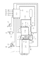
図1は本実施形態の車両の走行制御装置を備えた車両の駆動系を示す概略構成図であり、以下同図に基づき本実施形態の構成について説明する。 FIG. 1 is a schematic configuration diagram showing a drive system of a vehicle provided with the vehicle travel control device of the present embodiment, and the configuration of the present embodiment will be described based on the same figure.
本実施形態における車両1はトラックであり、走行用動力源としてディーゼルエンジン(以下、エンジンという)2が搭載されている。エンジン2の出力軸2aにはクラッチ装置3を介して自動変速機(以下、単に変速機という)4の入力軸4aが接続され、クラッチ装置3の接続時にエンジン2の回転が変速機4に伝達されるようになっている。当該変速機4は、例えば前進12段及び後進1段を備えた手動式変速機をベースとしたものであり、以下に述べるように、その変速操作及び変速に伴うクラッチ装置3の断接操作を自動化した、いわゆるAMT(Automated Manual Transmission)である。
The vehicle 1 in this embodiment is a truck, and a diesel engine (hereinafter referred to as an engine) 2 is mounted as a traveling power source. An input shaft 4 a of an automatic transmission (hereinafter simply referred to as a transmission) 4 is connected to the
クラッチ装置3は、フライホイール5にクラッチ板6をプレッシャスプリング7により圧接させて接続される一方、フライホイール5からクラッチ板6を離間させることにより切断される摩擦式クラッチとして構成されている。クラッチ板6にはアウタレバー8を介してエアシリンダ9が連結され、エアシリンダ9には電磁弁10が介装されたエア通路11を介して圧縮エアを充填したエアタンク12が接続されている。
The clutch device 3 is configured as a friction clutch that is connected to the flywheel 5 by press-contacting the
電磁弁10の開弁時にはエアタンク12からエア通路11を介してエアシリンダ9に圧縮エアが供給され、エアシリンダ9が作動してアウタレバー8を介してクラッチ板6をフライホイール5から離間させ、これによりクラッチ装置3が接続状態から切断状態に切り替えられる。一方、電磁弁10が閉弁すると、圧縮エアの供給中止によりエアシリンダ9が作動しなくなることから、クラッチ板6はプレッシャスプリング7によりフライホイール5に圧接され、これによりクラッチ装置3は切断状態から接続状態に切り替えられる。このように電磁弁10の開閉に応じてエアシリンダ9が作動して、クラッチ装置3を自動的に断接操作可能になっている。
When the
変速機4には変速段を切り替えるためのギヤシフトユニット13が設けられ、図示はしないがギヤシフトユニット13は、変速機4内の各変速段に対応するシフトフォークを作動させる複数のエアシリンダ、及び各エアシリンダを作動させる複数の電磁弁を内蔵している。ギヤシフトユニット13はエア通路14を介して上記したエアタンク12と接続されており、各電磁弁の開閉に応じてエアタンク12からの圧縮エアが対応するエアシリンダに供給され、そのエアシリンダが作動して対応するシフトフォークを切替操作すると、切替操作に応じて変速機4の変速段のギヤ入れが行われる。このようにギヤシフトユニット13の電磁弁の開閉に応じてエアシリンダが作動して、変速機4を自動的に変速操作可能になっている。なお、本実施形態では主にエアによりクラッチ装置3及び変速機4を作動させているが、作動方式はこれに限られず、例えば油圧を用いてもよい。
The transmission 4 is provided with a
車両1内には、図示しない入出力装置、制御プログラムや制御マップ等の記憶に供される記憶装置(ROM、RAMなど)、中央処理装置(CPU)、タイマカウンタなどを備えたECU(制御ユニット)20が設置されており、エンジン2、クラッチ装置3、変速機4の総合的な制御を行う。
In the vehicle 1, an ECU (control unit) including an input / output device (not shown), a storage device (ROM, RAM, etc.) used for storing control programs and control maps, a central processing unit (CPU), a timer counter, etc. ) 20 is installed, and comprehensive control of the
ECU20の入力側には、例えば、運転席に設けられたシフトレバー15の切替位置を検出するレバー位置センサ21、アクセルペダル16の操作量(アクセル開度)を検出するアクセルセンサ22、ブレーキペダル17の操作を検出するブレーキスイッチ23、変速機4の現変速段を検出する変速段センサ24、車両1が走行している路面の勾配を検出する勾配センサ25、エンジン2の回転速度からエンジン回転数を検出するエンジン回転数センサ26、変速機4の出力軸4bに設けられて出力軸回転速度から車速を検出する車速センサ27、車両1の加速度を検出する加速度センサ28、などのセンサ類が接続されている。
On the input side of the
また、ECU20の出力側には、上記したクラッチ装置3の電磁弁10、ギヤシフトユニット13の各電磁弁などが接続されると共に、図示はしないが、エンジン2の燃料噴射弁などが接続されている。なお、このように単一のECU20で総合的に制御することなく、例えばECU20とは別にエンジン制御専用のECUを備えるようにしてもよい。
Further, the
そして、例えばECU20は、エンジン回転数センサ26により検出されたエンジン回転数及びアクセルセンサ22により検出されたアクセル開度に基づき、図示しないマップからエンジン2の各気筒への燃料噴射量を算出すると共に、エンジン回転数及び燃料噴射量に基づき図示しないマップから燃料噴射時期を算出する。そして、これらの算出値に基づき各気筒の燃料噴射弁を駆動制御しながらエンジン2を運転する。
For example, the
また、ECU20は、レバー位置センサ21によりシフトレバー15のD(ドライブ)レンジへの切替が検出されているときには自動変速モードを実行し、アクセル開度及び車速センサ27により検出された車速に基づき、後述するシフトマップから目標変速段を算出する。そして、クラッチ装置3の電磁弁10を開閉してエアシリンダ9によりクラッチ装置3を断接操作させながら、ギヤシフトユニット13の所定の電磁弁を開閉してエアシリンダにより対応するシフトフォークを切替操作して目標変速段にギヤ入れし、これにより常に適切な変速段をもって車両を走行させる。
The
なお、シフトレバー15が選択可能なシフト位置としては、駐車時に選択するP(パーキング)レンジ、変速機4のギヤをニュートラルとするN(ニュートラル)レンジ、前進走行時に選択するD(ドライブ)レンジ、後進時に選択するR(リバース)レンジ、手動で変速段をシフトアップ又はシフトダウン可能なM(マニュアル)レンジ等がある。
The shift position that can be selected by the
また、車両1は、後述する惰性走行のオン、オフを行う惰性走行スイッチ29、及びブレーキペダル17の操作に応じた制動以外で制動力を生じさせる補助ブレーキ(補助ブレーキ手段)のオン、オフを行う補助ブレーキスイッチ30も備えている。補助ブレーキとしては、例えば、排気ブレーキ、エンジン2の圧縮開放ブレーキ、リターダがある。
In addition, the vehicle 1 turns on and off an
また、ECU20は、運転者により設定された目標車速を維持するようにエンジン2を制御するオートクルーズ制御を実行可能である(オートクルーズ制御手段)。運転者により図示しないオートクルーズ制御の実行スイッチが操作されて目標車速が設定されると、ECU20は車速を目標車速とするようにエンジン2のトルクや制動力を制御して加速及び減速を行う。
Further, the
さらに、ECU20は、車両走行中に以下に説明する各種条件が成立した際に、変速機4のギヤをニュートラル状態とし、且つクラッチ装置3を接続状態とすることで惰性走行を実行する(惰性走行制御手段)。
Further, the
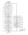
ここで、図2を参照すると、ECU20が実行するオートクルーズ制御中の惰性走行制御ルーチンを表すフローチャートが示されており、以下同フローチャートに沿って惰性走行制御について詳しく説明する。
Here, referring to FIG. 2, there is shown a flowchart showing an inertial traveling control routine during auto-cruise control executed by the
まず、ECU20は、ステップS1として、惰性走行を実行しているか否かを判別する。当該判別結果が偽(No)である場合は、ステップS2に進む。これ以降のステップS2からS12は惰性走行の開始条件に相当する。 First, ECU20 discriminate | determines whether inertia running is performed as step S1. If the determination result is false (No), the process proceeds to step S2. Subsequent steps S2 to S12 correspond to the starting condition for inertial running.
ステップS2においてECU20は、車両1がキーオン状態であり、エンジン2が稼働中であるか否かを判別する。当該判別結果が偽(No)である場合、即ち車両1が駐車中でキーオフ状態である場合や、エンジン2が停止している場合には惰性走行を実行できないため当該ルーチンをリターンする。一方、当該判別結果が真(Yes)である場合は、ステップS3に進む。
In step S2, the
ステップS3においてECU20は、惰性走行スイッチ29がオン状態であり、且つ補助ブレーキスイッチ30がオフ状態であるか否かを判別する。当該判別結果が偽(No)である場合、即ち運転者により惰性走行スイッチ29がオフに操作されている場合や、補助ブレーキを使用すべく補助ブレーキスイッチ30がオン状態である場合には、運転者に惰性走行を行う意思はないと推定できるため、当該ルーチンをリターンする。一方、当該判別結果が真(Yes)である場合は、運転者には惰性走行を行う意思はあると推定できることから、次のステップS4に進む。
In step S3, the
ステップS4においてECU20は、レバー位置センサ21の情報からシフトレバー15がDレンジにあるか、アクセルセンサ22の情報からアクセル開度が0(アクセルオフ状態)であるか、ブレーキスイッチ23の情報からブレーキオフ状態であるか否かを判別する。当該判別結果が偽(No)である場合、即ちシフト位置がDレンジ以外である場合や、アクセルペダル16又はブレーキペダル17の踏み込みがある場合には惰性走行は行わず、当該ルーチンをリターンする。一方、当該判別結果が真(Yes)である場合、即ち自動変速を行うDレンジであり、アクセルペダル16及びブレーキペダル17の踏み込みがない場合には、ステップS5に進む。
In step S4, the
ステップS5においてECU20は、上述したオートクルーズ制御を実行中であるか否かを判別する。当該判別結果が偽(No)である場合、即ちオートクルーズ制御を実行していない場合は、当該ルーチンをリターンする。当該判別結果が真(Yes)である場合はステップS6に進む。
In step S5, the
ステップS6においてECU20は、変速段センサ24の情報から現在選択されている変速段が予め定めた所定変速段以上であるか否かを判別する。この所定変速段はエンジンブレーキの影響が少ない変速段(例えば7速)に設定される。当該判別結果が偽(No)である場合、即ちエンジンブレーキの影響が大きい比較的低速段である場合は、惰性走行を実行することでエンジンブレーキによる制動力が大幅に低減されることで運転者に違和感を与えるおそれがあるため、惰性走行を行わず当該ルーチンをリターンする。一方、当該判別結果が真(Yes)である場合は、エンジンブレーキの影響が少なく、惰性走行を行ったとしても運転者に違和感を与えにくいことから、次のステップS7に進む。
In step S <b> 6, the
ステップS7においてECU20は、勾配センサ25の情報から現在車両1が走行している路面の勾配が予め定めた所定勾配範囲内であるか否かを判別する。この所定勾配範囲は緩い登坂路から緩い降坂路に相当する範囲(例えば−5%〜+5%)に設定されている。当該判別結果が偽(No)である場合、即ち所定勾配範囲外の登坂路や降坂路である場合は、惰性走行を実行しエンジン2を駆動系から切り離すことで車速が大きく変動し運転者に違和感を与えるおそれがあることから、惰性走行を実行することなく当該ルーチンをリターンする。一方、当該判別結果が真(Yes)である場合、即ち勾配が平坦路近辺である場合には、惰性走行実行時の車速の変動が少なく運転者に違和感与えにくいことから、次のステップS8に進む。
In step S7, the
ステップS8においてECU20は、エンジン回転数センサ26の情報から現在のエンジン回転数が予め定めた所定回転数以下であるか否かを判別する。当該所定回転数はエンジンブレーキの影響が少ない回転数(例えば1000rpm)に設定される。当該判別結果が偽(No)である場合、即ちエンジン回転数が比較的高いとエンジンブレーキによる制動力も大きく、その状態で惰性走行を実行すれば急に制動力が失われ運転者に違和感を与えることから、惰性走行を行わずに当該ルーチンをリターンする。一方、当該判別結果が真(Yes)である場合、即ちエンジン回転数が比較的低い場合には、エンジンブレーキの影響も少なく、惰性走行実行による制動力の変化も少なく運転者に違和感を与えにくいことから、次のステップS9に進む。
In step S8, the
ステップS9においてECU20は、車速センサ27の情報から現在の車速が所定車速範囲内であるか否かを判別する。当該所定車速範囲は、例えば停車相当の速度(例えば4km/h)から高速走行(例えば90km/h)の範囲である。当該判別結果が偽(No)である場合、即ち停車直前の極低車速時には惰性走行による燃費向上効果が低く、高速走行時は安全性を考慮しエンジンブレーキによる制動力が失われないよう、惰性走行は行わず当該ルーチンをリターンする。一方、当該判別結果が真(Yes)である場合は、エンジンブレーキによる影響も少なく、惰性走行による燃費向上効果も得られることから、次のステップS10に進む。
In step S9, the
ステップS10においてECU20は、加速度センサ28の情報あるいは車速の時間的変化(時間微分した値)から現在の車両1の加速度が所定加速度範囲内であるか否かを判別する。当該判別結果が偽(No)である場合、即ち例えば平坦路や緩い登坂路を走行しており減速している状態で惰性走行を行えば急に制動力が抜けた感じを与え、緩い降坂路を走行しており加速している状態で惰性走行を行えば加速度が増して恐怖感を与えるおそれがあることから、惰性走行は行わず当該ルーチンをリターンする。一方、当該判別結果が真(Yes)である場合、即ち加減速の度合いが小さい場合は、惰性走行実行時の変化も少なく運転者に違和感を与えにくいことから、ステップS11に進む。
In step S10, the
ステップS11においてECU20は、車速センサ27の情報から現在の車速がオートクルーズ制御における目標車速に対して所定の許容速度範囲(例えば+5〜−5km/h)内にあるか否かを判別する。ここでの所定の許容速度範囲は、目標車速近傍で、惰性走行を実行した場合に目標車速を維持するのに影響のでない程度の範囲に設定される。
In step S11, the
ステップS11の判別結果が偽(No)である場合、例えば車速が許容速度範囲より低く目標車速に向けて加速しているような場合や、車速が許容速度範囲より高く減速しなければならないような場合は、惰性走行を行うことで目標車速を維持できなくなるおそれがあるため、惰性走行は行わず当該ルーチンをリターンする。一方、当該判別結果が真(Yes)である場合、即ち車速が目標車速から許容速度範囲内にある場合は次のステップS12に進む。 When the determination result in step S11 is false (No), for example, when the vehicle speed is lower than the allowable speed range and the vehicle is accelerating toward the target vehicle speed, or the vehicle speed must be higher than the allowable speed range. In such a case, since the target vehicle speed may not be maintained by performing inertial traveling, the routine is returned without performing inertial traveling. On the other hand, when the determination result is true (Yes), that is, when the vehicle speed is within the allowable speed range from the target vehicle speed, the process proceeds to the next step S12.
ステップS12においてECU20は、エンジン2に対する燃料噴射量からエンジン2が発生させている実エンジントルクを算出し、当該実エンジントルクが予め定めた所定のトルク範囲(例えば、最大トルクに対して0から5%)内であるか否かを判別する。当該判別結果が偽(No)である場合、即ちオートルクーズ制御の下でエンジン2の駆動力により加速している場合やエンジン2の燃料をカットして負のトルク(エンジンブレーキ)により減速しているような場合は、惰性走行を行うことで目標車速を維持できなくなるおそれがあるため、惰性走行は行わず当該ルーチンをリターンする。一方、当該判別結果が真(Yes)である場合、即ちエンジントルクが所定トルク範囲内の比較的低いエンジントルクである場合には、次のステップS13に進む。
In step S12, the
ステップS13においてECU20は、クラッチ装置3を接続状態とし、且つ変速機4のギヤをニュートラル状態とすることでオートクルーズ制御中に惰性走行を実行し、当該ルーチンをリターンする。なお、惰性走行実行中、エンジン2はアイドリング運転させておく。
In step S13, the
このようにオートルクーズ制御中であって、車速が目標車速に対し所定の許容速度範囲内であり、且つ実エンジントルクが所定のトルク範囲内にある場合には惰性走行を実行しても車速やトルクの変化も少なく、オートクルーズ制御における目標車速を維持することができる。また車速やトルクへの影響を少ないことから、運転者に違和感を与えることなく自然な形で惰性走行を実行することができる。 As described above, when the auto torque control is being performed, and the vehicle speed is within the predetermined allowable speed range with respect to the target vehicle speed, and the actual engine torque is within the predetermined torque range, the vehicle speed and torque can be increased even if inertial running is executed. Therefore, the target vehicle speed in the auto cruise control can be maintained. In addition, since the influence on the vehicle speed and torque is small, coasting can be executed in a natural manner without giving the driver a sense of incongruity.
惰性走行を実行すると、上記ステップS1の判別結果は真(Yes)となり、ステップS14に進む。これ以降のステップS14からS19は惰性走行の終了条件に相当する。 When inertial running is executed, the determination result in step S1 is true (Yes), and the process proceeds to step S14. Subsequent steps S14 to S19 correspond to the coasting end condition.
ステップS14においてECU20は、アクセルセンサ22の情報からアクセルがオン状態であるか否かを判別する。当該判別結果が偽(No)である場合は、即ちアクセルオフ状態が維持されている場合には、ステップS15に進む。
In step S <b> 14, the
ステップS15においてECU20は、ブレーキスイッチ23の情報からブレーキがオン状態であるか否かを判別する。当該判別結果が偽(No)である場合、即ちブレーキオフ状態が維持されている場合には、ステップS16に進む。
In step S15, the
ステップS16においてECU20は、勾配センサ25の情報からこの時点で車両1が走行している路面の勾配が予め定めた所定勾配以上であるか否かを判別する。この所定勾配は例えば急登坂路に相当する勾配(例えば10%)に設定される。当該判別結果が偽(No)である場合、即ち平坦路や降坂路、緩い登坂路を走行している場合は、ステップS17に進む。
In step S16, the
ステップS17においてECU20は、加速度センサ28の情報からこの時点での車両1の加速度が予め定めた所定加速度以上である否かを判別する。当該所定加速度は、不要な加速を防ぐとともに、惰性走行を終了してエンジンブレーキが生じたときに急な減速感を与えない程度の加速度に設定される。当該判別結果が偽(No)である場合は、ステップS18に進む。
In step S <b> 17, the
ステップS18においてECU20は、車速センサ27の情報から現在の車速がオートクルーズ制御における目標車速に対して所定の許容速度範囲(+5〜−5km/h)外にあるか否かを判別する。なお、当該許容速度範囲は上記ステップS11の許容速度範囲と同じであってもよいし、範囲を異ならせてもよい。当該判別結果が偽(No)である場合、即ち車速が目標車速近傍に維持されている場合はステップS19に進む。
In step S18, the
ステップS19においてECU20は、制御エラーが発生しているか否かを判別する(制御エラー検出手段)。ここでの制御エラーとは、各センサや制御ユニットとの通信不具合等であり、惰性走行を行う上で必要な情報を得られない場合をいう。当該判別結果が偽(No)である場合は、制御エラーもないことから、惰性走行を維持して当該ルーチンをリターンする。
In step S19, the
一方、上記ステップS14〜S19のうちいずれか1つでも判別結果が真(Yes)となった場合は、ステップS20に進み、ECU20は惰性走行を終了する。これにより、アクセルオン状態又はブレーキオン状態となり運転者の操作が開始された場合には、運転者の操作に応じた走行に速やかに復帰させることができる。また、急登坂路に入った場合、車両1が所定加速度以上に加速し始めた場合、車速がオートルクーズ制御の目標車速に対する許容範囲を超えた場合、エンジントルクが所定トルク範囲外となった場合、又は制御エラーが生じた場合には、エンジン2の駆動力又はエンジンブレーキによる制動力を使用した安定的な走行に速やかに復帰させることができる。
On the other hand, if the determination result is true (Yes) in any one of the steps S14 to S19, the process proceeds to step S20, and the
以上のように、上述した惰性走行の開始条件及び終了条件に従って惰性走行制御を行うことで、運転者に違和感を与えることなく、適切なタイミングで惰性走行を実行し、燃費を向上させることができる。 As described above, by performing inertial traveling control in accordance with the above-described inertial traveling start condition and end condition, inertial traveling can be performed at an appropriate timing and fuel efficiency can be improved without causing the driver to feel uncomfortable. .
以上で本発明に係る車両の走行制御装置の実施形態についての説明を終えるが、実施形態は上記実施形態に限られるものではない。 Although the description of the embodiment of the vehicle travel control device according to the present invention has been completed above, the embodiment is not limited to the above embodiment.
上記実施形態では、車両1をトラックとしているが、本発明を適用することのできる車両はこれに限られるものではなく、乗用車にも適用することができる。 In the said embodiment, although the vehicle 1 is made into the track, the vehicle which can apply this invention is not restricted to this, It can apply also to a passenger car.
また、上記実施形態では、エンジン2はディーゼルエンジンであるが、エンジンはこれに限られず、例えばガソリンエンジンでもよい。また、上記実施形態では、変速機は前進12段後進1段の変速段を有したものであるが、変速機の構成はこれに限られず、例えば前進6段、又は前進16段等の変速機であってもよい。
Moreover, in the said embodiment, although the
また、上記実施形態では、変速機4のギヤをニュートラル状態とし、且つクラッチ装置3を接続状態とすることで惰性走行を行っているが、惰性走行はエンジンを駆動系から切り離せればよく、これに限られるものではない。例えばクラッチ装置を切断状態とするのみ、又はクラッチ装置3を切断状態とするとともに変速機のギヤをニュートラル状態として惰性走行を行ってもよい。 In the above embodiment, the inertial running is performed by setting the gear of the transmission 4 in the neutral state and the clutch device 3 in the connected state. However, the inertial traveling may be performed by disconnecting the engine from the drive system. It is not limited to. For example, the inertial running may be performed only by setting the clutch device to the disconnected state or setting the clutch device 3 to the disconnected state and setting the gear of the transmission to the neutral state.
また、上記実施形態のステップS2からS12として示される惰性走行の開始条件については、その判別の数や順番はこれに限られるものではない。本発明においては、少なくともステップS2〜S5、S11、S12の条件を備えていればよく、その他の条件は車両に応じて変更してもよい。 Moreover, about the start conditions of the inertia running shown as step S2 to S12 of the said embodiment, the number and order of the determination are not restricted to this. In the present invention, at least the conditions of steps S2 to S5, S11, and S12 may be provided, and other conditions may be changed according to the vehicle.
1 車両
2 エンジン
3 クラッチ装置
4 変速機
15 シフトレバー
16 アクセルペダル
17 ブレーキペダル
20 ECU(オートクルーズ制御手段、惰性走行制御手段、エラー検出手段)
21 レバー位置センサ
22 アクセルセンサ
23 ブレーキスイッチ
24 変速段センサ
25 勾配センサ(路面勾配検出手段)
26 エンジン回転数センサ(エンジン回転数検出手段)
27 車速センサ(車速検出手段)
28 加速度センサ(加速度検出手段)
29 惰性走行スイッチ
30 補助ブレーキスイッチ
DESCRIPTION OF SYMBOLS 1
21
26 Engine speed sensor (engine speed detection means)
27 Vehicle speed sensor (vehicle speed detection means)
28 Acceleration sensor (acceleration detection means)
29
Claims (8)
少なくとも自動変速により駆動を行うDレンジを含むシフト位置の中から1つのシフト位置を選択するシフトレバーと、
運転者により設定された目標車速を維持するように前記車両の駆動力を調整するオートクルーズ制御を行うオートクルーズ制御手段と、
前記車両の車速を検出する車速検出手段と、
前記エンジンが稼働状態であり、前記シフトレバーにより選択されるシフト位置がDレンジであり、アクセルペダル及びブレーキペダルの踏み込みがなく、前記オートクルーズ制御手段によるオートクルーズ制御中であり、前記車速検出手段によって検出された前記車両の車速が前記目標車速に対して所定の許容速度範囲にあり、前記エンジンのエンジントルクが所定のトルク範囲内であるという惰性走行開始条件が成立したときに、前記クラッチの切断状態及び前記自動変速機のギヤのニュートラル状態の少なくともいずれかの状態とすることで惰性走行を実行する惰性走行制御手段と、
を備える車両の走行制御装置。 A vehicle travel control device in which an engine that is a vehicle drive source is connected to an automatic transmission via a clutch,
A shift lever for selecting one shift position from among shift positions including a D range that is driven by at least automatic shifting;
Auto cruise control means for performing auto cruise control for adjusting the driving force of the vehicle so as to maintain the target vehicle speed set by the driver;
Vehicle speed detecting means for detecting the vehicle speed of the vehicle;
The engine is in an operating state, the shift position selected by the shift lever is in the D range, the accelerator pedal and the brake pedal are not depressed, and the auto cruise control means is performing auto cruise control, and the vehicle speed detection means When the inertial running start condition that the vehicle speed detected by the vehicle is within a predetermined allowable speed range with respect to the target vehicle speed and the engine torque of the engine is within the predetermined torque range is satisfied, Inertial running control means for executing inertial running by setting at least one of a disconnected state and a neutral state of the gear of the automatic transmission;
A vehicle travel control apparatus comprising:
前記ブレーキペダルの操作に応じた制動以外で制動力を生じさせる補助ブレーキ手段と、
前記補助ブレーキ手段のオン、オフを切り替え可能な補助ブレーキスイッチとを備え、
前記惰性走行制御手段は、前記惰性走行開始条件に加えて、前記惰性走行スイッチがオンであり、前記補助ブレーキスイッチがオフであることを条件に前記惰性走行を実行する請求項1記載の車両の走行制御装置。 An inertial travel switch capable of switching on and off the inertial travel by the inertial travel control means;
Auxiliary brake means for generating a braking force other than braking according to the operation of the brake pedal;
An auxiliary brake switch capable of switching on and off the auxiliary brake means,
2. The vehicle according to claim 1, wherein the inertial traveling control unit executes the inertial traveling on the condition that the inertial travel switch is on and the auxiliary brake switch is off in addition to the inertial travel start condition. Travel control device.
前記惰性走行制御手段は、前記惰性走行開始条件に加えて、前記路面勾配検出手段により検出される路面勾配が所定の勾配範囲内にあることを条件に前記惰性走行を実行する請求項1から3のいずれか一項に記載の車両の走行制御装置。 Road surface gradient detecting means for detecting the gradient of the road surface on which the vehicle is running,
The inertial traveling control means executes the inertial traveling on the condition that the road surface gradient detected by the road surface gradient detecting means is within a predetermined gradient range in addition to the inertial traveling start condition. The vehicle travel control device according to any one of the above.
前記惰性走行制御手段は、前記惰性走行開始条件に加えて、前記エンジン回転数検出手段により検出されるエンジン回転数が所定回転数以下であることを条件に前記惰性走行を実行する請求項1から4のいずれか一項に記載の車両の走行制御装置。 Engine speed detecting means for detecting the engine speed of the vehicle;
The inertial running control means executes the inertial running on the condition that the engine speed detected by the engine speed detecting means is not more than a predetermined speed in addition to the inertia running start condition. The vehicle travel control device according to claim 4.
前記惰性走行制御手段は、前記惰性走行開始条件に加えて、前記加速度検出手段により検出される加速度が所定の加速度範囲内であることを条件に前記惰性走行を実行する請求項1から5のいずれか一項に記載の車両の走行制御装置。 An acceleration detecting means for detecting the acceleration of the vehicle;
The coasting control means, wherein in addition to the coasting start condition, any acceleration detected by the acceleration detecting means from claim 1 to perform the coasting condition that is within a predetermined acceleration range of 5 The vehicle travel control device according to claim 1.
前記車両の加速度を検出する加速度検出手段と、
前記車両の制御エラーを検出するエラー検出手段と、を備え、
前記惰性走行制御手段は、前記惰性走行を実行中に前記路面勾配検出手段により検出される路面勾配が所定勾配以上になったとき、前記加速度検出手段により検出される加速度が所定加速度以上となったとき、前記エラー検出手段により制御エラーを検出したとき、又は前記車両の車速が前記目標車速に対して前記所定の許容速度範囲外となったとき、
には、前記惰性走行を終了する請求項1から6のいずれか一項に記載の車両の走行制御装置。 Road surface gradient detecting means for detecting the gradient of the road surface on which the vehicle is traveling;
Acceleration detecting means for detecting acceleration of the vehicle;
Error detection means for detecting a control error of the vehicle,
When the road surface gradient detected by the road surface gradient detecting unit becomes equal to or greater than a predetermined gradient during the inertial running, the inertial traveling control unit detects that the acceleration detected by the acceleration detecting unit is equal to or greater than a predetermined acceleration . When a control error is detected by the error detection means, or when the vehicle speed of the vehicle falls outside the predetermined allowable speed range with respect to the target vehicle speed,
The traveling control device for a vehicle according to any one of claims 1 to 6, terminating the coasting.
Priority Applications (1)
| Application Number | Priority Date | Filing Date | Title |
|---|---|---|---|
| JP2014257548A JP6478024B2 (en) | 2014-12-19 | 2014-12-19 | Vehicle travel control device |
Applications Claiming Priority (1)
| Application Number | Priority Date | Filing Date | Title |
|---|---|---|---|
| JP2014257548A JP6478024B2 (en) | 2014-12-19 | 2014-12-19 | Vehicle travel control device |
Publications (2)
| Publication Number | Publication Date |
|---|---|
| JP2016117368A JP2016117368A (en) | 2016-06-30 |
| JP6478024B2 true JP6478024B2 (en) | 2019-03-06 |
Family
ID=56242753
Family Applications (1)
| Application Number | Title | Priority Date | Filing Date |
|---|---|---|---|
| JP2014257548A Active JP6478024B2 (en) | 2014-12-19 | 2014-12-19 | Vehicle travel control device |
Country Status (1)
| Country | Link |
|---|---|
| JP (1) | JP6478024B2 (en) |
Families Citing this family (3)
| Publication number | Priority date | Publication date | Assignee | Title |
|---|---|---|---|---|
| KR20180067984A (en) * | 2016-12-13 | 2018-06-21 | 현대자동차주식회사 | Method and apparatus for controlling mhsg of mild hybrid electric vehicle |
| JP2018159317A (en) * | 2017-03-22 | 2018-10-11 | いすゞ自動車株式会社 | Travel control device, vehicle and travel control method |
| JP2023066790A (en) * | 2021-10-29 | 2023-05-16 | 株式会社J-QuAD DYNAMICS | Travelling control device, travelling control method and travelling control program |
Family Cites Families (8)
| Publication number | Priority date | Publication date | Assignee | Title |
|---|---|---|---|---|
| DE102004033081A1 (en) * | 2003-12-20 | 2005-07-21 | Robert Bosch Gmbh | Method and device for operating a drive unit of a vehicle |
| JP5434868B2 (en) * | 2010-09-28 | 2014-03-05 | アイシン・エィ・ダブリュ株式会社 | Control device for automatic transmission and control program for automatic transmission |
| JP5747511B2 (en) * | 2011-01-07 | 2015-07-15 | いすゞ自動車株式会社 | Coasting control device |
| JP2012219986A (en) * | 2011-04-13 | 2012-11-12 | Mitsubishi Fuso Truck & Bus Corp | Travel control device for vehicle |
| JP5724985B2 (en) * | 2012-10-19 | 2015-05-27 | トヨタ自動車株式会社 | Vehicle travel control device |
| JP6367517B2 (en) * | 2012-10-19 | 2018-08-01 | トヨタ自動車株式会社 | Vehicle travel control device |
| JP2014091398A (en) * | 2012-11-02 | 2014-05-19 | Toyota Motor Corp | Vehicle travel control system |
| JP2014113863A (en) * | 2012-12-07 | 2014-06-26 | Hino Motors Ltd | Fuel economy-saving drive guidance device |
-
2014
- 2014-12-19 JP JP2014257548A patent/JP6478024B2/en active Active
Also Published As
| Publication number | Publication date |
|---|---|
| JP2016117368A (en) | 2016-06-30 |
Similar Documents
| Publication | Publication Date | Title |
|---|---|---|
| JP5935886B2 (en) | Vehicle control device | |
| EP2620339B1 (en) | Control of a freewheel mode for a motor vehicle with engine off | |
| US9481345B2 (en) | Control device of a motor vehicle and method for operating same | |
| CN108204454B (en) | Control device for all-wheel drive vehicle | |
| WO2013190651A1 (en) | Vehicle control device | |
| JP6551648B2 (en) | Vehicle travel control device | |
| JP6551647B2 (en) | Vehicle travel control device | |
| JP6478024B2 (en) | Vehicle travel control device | |
| JP5999323B2 (en) | Shift control device for automatic transmission | |
| JP6650254B2 (en) | Vehicle travel control device | |
| JP6555463B2 (en) | Vehicle travel control device | |
| JP6468423B2 (en) | Vehicle travel control device | |
| JP6597951B2 (en) | Vehicle travel control device | |
| JP6414461B2 (en) | Vehicle travel control device | |
| JP2014001823A (en) | Shift control device of automatic transmission | |
| JP2017096432A (en) | Vehicular inter-vehicle distance controller | |
| JP5880828B2 (en) | Automatic transmission clutch control device | |
| JP6213721B2 (en) | Control device for automatic transmission | |
| JP5868585B2 (en) | Vehicle travel control device | |
| JP2020133754A (en) | Automatic transmission controller | |
| JP6070921B2 (en) | Control device for automatic transmission | |
| JP6410017B2 (en) | Automatic transmission control device | |
| JP2017096195A (en) | Vehicular travel controller | |
| JP2016011614A (en) | Engine automatic stop/start control device | |
| WO2019111397A1 (en) | Control method and control device for vehicle |
Legal Events
| Date | Code | Title | Description |
|---|---|---|---|
| A621 | Written request for application examination |
Free format text: JAPANESE INTERMEDIATE CODE: A621 Effective date: 20171127 |
|
| A977 | Report on retrieval |
Free format text: JAPANESE INTERMEDIATE CODE: A971007 Effective date: 20180816 |
|
| A131 | Notification of reasons for refusal |
Free format text: JAPANESE INTERMEDIATE CODE: A131 Effective date: 20180822 |
|
| A601 | Written request for extension of time |
Free format text: JAPANESE INTERMEDIATE CODE: A601 Effective date: 20181003 |
|
| A521 | Written amendment |
Free format text: JAPANESE INTERMEDIATE CODE: A523 Effective date: 20181213 |
|
| TRDD | Decision of grant or rejection written | ||
| A01 | Written decision to grant a patent or to grant a registration (utility model) |
Free format text: JAPANESE INTERMEDIATE CODE: A01 Effective date: 20190109 |
|
| A61 | First payment of annual fees (during grant procedure) |
Free format text: JAPANESE INTERMEDIATE CODE: A61 Effective date: 20190122 |
|
| R150 | Certificate of patent or registration of utility model |
Ref document number: 6478024 Country of ref document: JP Free format text: JAPANESE INTERMEDIATE CODE: R150 |
|
| R250 | Receipt of annual fees |
Free format text: JAPANESE INTERMEDIATE CODE: R250 |