JP6477305B2 - Electronic device and press detection program - Google Patents

Electronic device and press detection program Download PDF

Info

Publication number
JP6477305B2
JP6477305B2 JP2015134389A JP2015134389A JP6477305B2 JP 6477305 B2 JP6477305 B2 JP 6477305B2 JP 2015134389 A JP2015134389 A JP 2015134389A JP 2015134389 A JP2015134389 A JP 2015134389A JP 6477305 B2 JP6477305 B2 JP 6477305B2
Authority
JP
Japan
Prior art keywords
top panel
current
electronic device
unit
operation input
Prior art date
Legal status (The legal status is an assumption and is not a legal conclusion. Google has not performed a legal analysis and makes no representation as to the accuracy of the status listed.)
Expired - Fee Related
Application number
JP2015134389A
Other languages
Japanese (ja)
Other versions
JP2017016510A (en
Inventor
洋平 杉浦
洋平 杉浦
Current Assignee (The listed assignees may be inaccurate. Google has not performed a legal analysis and makes no representation or warranty as to the accuracy of the list.)
Fujitsu Ltd
Original Assignee
Fujitsu Ltd
Priority date (The priority date is an assumption and is not a legal conclusion. Google has not performed a legal analysis and makes no representation as to the accuracy of the date listed.)
Filing date
Publication date
Application filed by Fujitsu Ltd filed Critical Fujitsu Ltd
Priority to JP2015134389A priority Critical patent/JP6477305B2/en
Publication of JP2017016510A publication Critical patent/JP2017016510A/en
Application granted granted Critical
Publication of JP6477305B2 publication Critical patent/JP6477305B2/en
Expired - Fee Related legal-status Critical Current
Anticipated expiration legal-status Critical

Links

Images

Description

本発明は、電子機器、及び、押圧検出プログラムに関する。   The present invention relates to an electronic device and a press detection program.

従来より、表面に入力操作面を有する可動板と、可動板とわずかな絶縁間隔を隔てて配置され、可動板を背面から支持する支持基板と、入力操作面への押圧とその押圧位置を、可動板と支持基板上の対向面にそれぞれ形成された導電体層間の接触から検出し、押圧位置データを出力する押圧検出手段とを備えるタッチパネル入力装置がある。タッチパネル入力装置は、押圧を検出した際に、可動板又は支持基板を振動し、入力操作感を発生させる。また、対向する両面に一対の駆動電極が固着された圧電基板を、直接若しくは駆動電極を介して、可動板又は支持基板に固着し、入力操作面への押圧を検出した際に、一対の駆動電極に駆動電圧を印加して、伸縮する圧電基板により可動板又は支持基板を振動させることを特徴とする(例えば、特許文献1参照)。   Conventionally, a movable plate having an input operation surface on the surface, a support substrate that is arranged with a slight insulating interval from the movable plate, and supports the movable plate from the back surface, a pressure on the input operation surface and its pressing position, There is a touch panel input device including press detection means for detecting press position data detected from contact between conductive plates formed on a movable plate and opposing surfaces on a support substrate. When the touch panel input device detects a press, the touch panel input device vibrates the movable plate or the support substrate to generate an input operation feeling. In addition, when a piezoelectric substrate having a pair of drive electrodes fixed on both sides facing each other is fixed to a movable plate or a support substrate directly or via a drive electrode, and a pressure on the input operation surface is detected, a pair of drives A driving voltage is applied to the electrodes, and the movable plate or the support substrate is vibrated by the expanding and contracting piezoelectric substrate (see, for example, Patent Document 1).

特開2003−122507号公報JP 2003-122507 A

ところで、従来のタッチパネル入力装置は、圧電基板を振動させている場合に、利用者がタッチパネルを押圧しているのかどうかを検出することができない。このため、従来のタッチパネル入力装置は、使い勝手が良好ではない。   By the way, the conventional touch panel input device cannot detect whether the user is pressing the touch panel when the piezoelectric substrate is vibrated. For this reason, the conventional touch panel input device is not easy to use.

そこで、使い勝手の良好な電子機器、及び、押圧検出プログラムを提供することを目的とする。   Accordingly, it is an object of the present invention to provide a user-friendly electronic device and a press detection program.

本発明の実施の形態の電子機器は、操作面を有するトップパネルと、前記操作面に行われる操作入力の位置を検出する位置検出部と、前記操作面に振動を発生させる振動素子と、前記操作面への操作入力の位置に応じて、前記操作面に超音波帯の固有振動を発生させる駆動信号で前記振動素子を駆動する駆動制御部と、前記駆動制御部から前記振動素子に供給される電流量を検出する電流検出部と、前記位置検出部によって前記操作入力の位置が検出されている場合に、前記電流検出部によって検出される電流量と、前記駆動信号の電圧値との第1の比に基づいて、前記操作入力によって前記トップパネルが押圧されているかどうかを判定する押圧判定部とを含む。   An electronic apparatus according to an embodiment of the present invention includes a top panel having an operation surface, a position detection unit that detects a position of an operation input performed on the operation surface, a vibration element that generates vibration on the operation surface, A drive control unit that drives the vibration element with a drive signal that generates a natural vibration of an ultrasonic band on the operation surface according to a position of an operation input to the operation surface, and is supplied from the drive control unit to the vibration element. A current detection unit that detects a current amount to be detected, and a current amount detected by the current detection unit and a voltage value of the drive signal when the position of the operation input is detected by the position detection unit. And a pressing determination unit that determines whether the top panel is pressed by the operation input based on a ratio of 1.

使い勝手の良好な電子機器、及び、押圧検出プログラムを提供することができる。   A user-friendly electronic device and a press detection program can be provided.

実施の形態の電子機器100を示す斜視図である。It is a perspective view which shows the electronic device 100 of embodiment. 実施の形態の電子機器100を示す平面図である。It is a top view which shows the electronic device 100 of embodiment. 図2に示す電子機器100のA−A矢視断面を示す図である。It is a figure which shows the AA arrow cross section of the electronic device 100 shown in FIG. 超音波帯の固有振動によってトップパネル120に生じる定在波のうち、トップパネル120の短辺に平行に形成される波頭を示す図である。It is a figure which shows the wave front formed in parallel with the short side of the top panel 120 among the standing waves produced in the top panel 120 by the natural vibration of an ultrasonic band. 電子機器100のトップパネル120に生じさせる超音波帯の固有振動により、操作入力を行う指先に掛かる動摩擦力が変化する様子を説明する図である。It is a figure explaining a mode that the dynamic friction force applied to the fingertip which performs operation input changes with the natural vibration of the ultrasonic band produced in the top panel 120 of the electronic device. 実施の形態の電子機器100の構成を示す図である。It is a figure which shows the structure of the electronic device 100 of embodiment. 電流検出部180を示す図である。It is a figure which shows the electric current detection part 180. FIG. 押圧の有無と駆動信号の電圧及び電流との関係を示す図である。It is a figure which shows the relationship between the presence or absence of a press, and the voltage and electric current of a drive signal. 押圧力と、駆動信号の電流及び電圧の比との関係を示す図である。It is a figure which shows the relationship between pressing force and the ratio of the electric current and voltage of a drive signal. 図9に示す実験結果を押圧力と比Ip/Vpとの関係で纏めた図である。It is the figure which summarized the experimental result shown in FIG. 9 by the relationship between pressing force and ratio Ip / Vp. 電子機器100の操作の様子を示す図である。FIG. 3 is a diagram showing a state of operation of electronic device 100. 図11のように操作された場合における、押圧力、駆動信号の振幅、及び比Ip/Vpを示す図である。FIG. 12 is a diagram illustrating a pressing force, an amplitude of a drive signal, and a ratio Ip / Vp when operated as in FIG. 11. メモリ250に格納されるデータを示す図である。4 is a diagram showing data stored in a memory 250. FIG. メモリ250に格納されるデータを示す図である。4 is a diagram showing data stored in a memory 250. FIG. メモリ250に格納されるデータを示す図である。4 is a diagram showing data stored in a memory 250. FIG. アプリケーションプロセッサ220が実行する処理を示すフローチャートである。It is a flowchart which shows the process which the application processor 220 performs. 実施の形態1の第1変形例による、比の差分(Ip0/Vp0−Ip/Vp)と押圧変換係数PFとを関連付けたデータを示す図である。It is a figure which shows the data which linked | related the difference (Ip0 / Vp0-Ip / Vp) of ratio, and the press conversion coefficient PF by the 1st modification of Embodiment 1. FIG. 車両10の室内内のドライバーズシート11の周りを示す図である。FIG. 2 is a view showing the periphery of a driver's seat 11 in a vehicle 10. 実施の形態1の第2変形例の電子機器100Aを示す平面図である。FIG. 11 is a plan view showing an electronic device 100A of a second modification example of the first embodiment. 第3変形例の電子機器100Bを示す図である。It is a figure which shows the electronic device 100B of a 3rd modification. 第3変形例の電子機器100Bのタッチパッド160B2の断面を示す図である。It is a figure which shows the cross section of touchpad 160B2 of the electronic device 100B of a 3rd modification. 実施の形態2の電子機器100Cの構成を示す図である。It is a figure which shows the structure of the electronic device 100C of Embodiment 2. FIG. アプリケーションプロセッサ220Cが実行する処理を示すフローチャートである。It is a flowchart which shows the process which the application processor 220C performs.

以下、本発明の電子機器、及び、押圧検出プログラムを適用した実施の形態について説明する。   Embodiments to which an electronic device and a press detection program of the present invention are applied will be described below.

<実施の形態1>
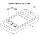
図1は、実施の形態1の電子機器100を示す斜視図である。
<Embodiment 1>
FIG. 1 is a perspective view showing an electronic apparatus 100 according to the first embodiment.

電子機器100は、一例として、タッチパネルを入力操作部とする、スマートフォン端末機、又は、タブレット型コンピュータである。電子機器100は、タッチパネルを入力操作部とする機器であればよいため、例えば、携帯情報端末機、又は、ATM(Automatic Teller Machine)のように特定の場所に設置されて利用される機器であってもよい。   As an example, the electronic device 100 is a smartphone terminal or a tablet computer using a touch panel as an input operation unit. The electronic device 100 may be any device that uses a touch panel as an input operation unit. For example, the electronic device 100 is a device that is installed and used in a specific place such as a portable information terminal or ATM (Automatic Teller Machine). May be.

電子機器100の入力操作部101は、タッチパネルの下にディスプレイパネルが配設されており、ディスプレイパネルにGUI(Graphic User Interface)による様々なボタン102A、又は、スライダー102B等(以下、GUI操作部102と称す)が表示される。   The input operation unit 101 of the electronic device 100 is provided with a display panel below the touch panel. Various buttons 102A or a slider 102B or the like (hereinafter referred to as GUI operation unit 102) using a GUI (Graphic User Interface) is provided on the display panel. Is displayed).

電子機器100の利用者は、通常、GUI操作部102を操作するために、指先で入力操作部101に触れる。   A user of the electronic device 100 usually touches the input operation unit 101 with a fingertip in order to operate the GUI operation unit 102.

次に、図2を用いて、電子機器100の具体的な構成について説明する。   Next, a specific configuration of the electronic device 100 will be described with reference to FIG.

図2は、実施の形態1の電子機器100を示す平面図であり、図3は、図2に示す電子機器100のA−A矢視断面を示す図である。なお、図2及び図3では、図示するように直交座標系であるXYZ座標系を定義する。   2 is a plan view showing electronic device 100 of the first embodiment, and FIG. 3 is a diagram showing a cross-section taken along line AA of electronic device 100 shown in FIG. 2 and 3, an XYZ coordinate system that is an orthogonal coordinate system is defined as shown.

電子機器100は、筐体110、トップパネル120、両面テープ130、振動素子140、タッチパネル150、ディスプレイパネル160、及び基板170を含む。   The electronic device 100 includes a housing 110, a top panel 120, a double-sided tape 130, a vibration element 140, a touch panel 150, a display panel 160, and a substrate 170.

筐体110は、例えば、樹脂製であり、図3に示すように凹部110Aに基板170、ディスプレイパネル160、及びタッチパネル150が配設されるとともに、両面テープ130によってトップパネル120が接着されている。   The housing 110 is made of, for example, resin, and as shown in FIG. 3, the substrate 170, the display panel 160, and the touch panel 150 are disposed in the recess 110 </ b> A, and the top panel 120 is bonded by the double-sided tape 130. .

トップパネル120は、平面視で長方形の薄い平板状の部材であり、透明なガラス、又は、ポリカーボネートのような強化プラスティックで作製される。トップパネル120の表面(Z軸正方向側の面)は、電子機器100の利用者が操作入力を行う操作面の一例である。   The top panel 120 is a thin flat plate member that is rectangular in plan view, and is made of transparent glass or a reinforced plastic such as polycarbonate. The surface of the top panel 120 (the surface on the Z-axis positive direction side) is an example of an operation surface on which the user of the electronic device 100 performs operation input.

トップパネル120は、Z軸負方向側の面に振動素子140が接着され、平面視における四辺が両面テープ130によって筐体110に接着されている。なお、両面テープ130は、トップパネル120の四辺を筐体110に接着できればよく、図3に示すように矩形環状である必要はない。   In the top panel 120, the vibration element 140 is bonded to the surface in the negative direction of the Z axis, and four sides in a plan view are bonded to the housing 110 with a double-sided tape 130. The double-sided tape 130 only needs to be able to bond the four sides of the top panel 120 to the housing 110, and does not have to be a rectangular ring as shown in FIG.

トップパネル120のZ軸負方向側にはタッチパネル150が配設される。トップパネル120は、タッチパネル150の表面を保護するために設けられている。なお、トップパネル120の表面に、さらに別なパネル又は保護膜等が設けられていてもよい。   A touch panel 150 is disposed on the Z-axis negative direction side of the top panel 120. The top panel 120 is provided to protect the surface of the touch panel 150. Further, another panel or a protective film may be provided on the surface of the top panel 120.

トップパネル120は、Z軸負方向側の面に振動素子140が接着された状態で、振動素子140が駆動されることによって振動する。実施の形態1では、トップパネル120の固有振動周波数でトップパネル120を振動させて、トップパネル120に定在波を生じさせる。ただし、トップパネル120には振動素子140が接着されているため、実際には、振動素子140の重さ等を考慮した上で、固有振動周波数を決めることが好ましい。   The top panel 120 vibrates when the vibration element 140 is driven in a state where the vibration element 140 is bonded to the surface in the negative Z-axis direction. In the first embodiment, the top panel 120 is vibrated at the natural vibration frequency of the top panel 120 to generate a standing wave in the top panel 120. However, since the vibration element 140 is bonded to the top panel 120, it is actually preferable to determine the natural vibration frequency in consideration of the weight of the vibration element 140 and the like.

振動素子140は、トップパネル120のZ軸負方向側の面において、Y軸正方向側において、X軸方向に伸延する短辺に沿って接着されている。振動素子140は、超音波帯の振動を発生できる素子であればよく、例えば、ピエゾ素子のような圧電素子を含むものを用いることができる。   The vibration element 140 is bonded to the surface of the top panel 120 on the Z-axis negative direction side along the short side extending in the X-axis direction on the Y-axis positive direction side. The vibration element 140 may be an element that can generate vibrations in an ultrasonic band. For example, an element including a piezoelectric element such as a piezoelectric element can be used.

振動素子140は、後述する駆動制御部から出力される駆動信号によって駆動される。振動素子140が発生する振動の振幅(強度)及び周波数は駆動信号によって設定される。また、振動素子140のオン/オフは駆動信号によって制御される。   The vibration element 140 is driven by a drive signal output from a drive control unit described later. The amplitude (intensity) and frequency of vibration generated by the vibration element 140 are set by the drive signal. Further, on / off of the vibration element 140 is controlled by a drive signal.

なお、超音波帯とは、例えば、約20kHz以上の周波数帯をいう。実施の形態1の電子機器100では、振動素子140が振動する周波数は、トップパネル120の振動数と等しくなるため、振動素子140は、トップパネル120の固有振動数で振動するように駆動信号によって駆動される。   In addition, an ultrasonic band means a frequency band about 20 kHz or more, for example. In the electronic device 100 according to the first embodiment, the frequency at which the vibration element 140 vibrates is equal to the frequency of the top panel 120. Therefore, the vibration element 140 is driven by a drive signal so as to vibrate at the natural frequency of the top panel 120. Driven.

タッチパネル150は、ディスプレイパネル160の上(Z軸正方向側)で、トップパネル120の下(Z軸負方向側)に配設されている。タッチパネル150は、電子機器100の利用者がトップパネル120に触れる位置(以下、操作入力の位置と称す)を検出する位置検出部の一例である。   The touch panel 150 is disposed on the display panel 160 (Z-axis positive direction side) and below the top panel 120 (Z-axis negative direction side). The touch panel 150 is an example of a position detection unit that detects a position where the user of the electronic device 100 touches the top panel 120 (hereinafter referred to as an operation input position).

タッチパネル150の下にあるディスプレイパネル160には、GUIによる様々なボタン等(以下、GUI操作部と称す)が表示される。このため、電子機器100の利用者は、通常、GUI操作部を操作するために、指先でトップパネル120に触れる。   On the display panel 160 below the touch panel 150, various buttons and the like (hereinafter referred to as GUI operation unit) by GUI are displayed. For this reason, the user of the electronic device 100 usually touches the top panel 120 with a fingertip in order to operate the GUI operation unit.

タッチパネル150は、利用者のトップパネル120への操作入力の位置を検出できる位置検出部であればよく、例えば、静電容量型又は抵抗膜型の位置検出部であればよい。ここでは、タッチパネル150が静電容量型の位置検出部である形態について説明する。タッチパネル150とトップパネル120との間に隙間があっても、静電容量型のタッチパネル150は、トップパネル120への操作入力を検出できる。   The touch panel 150 may be a position detection unit that can detect the position of an operation input to the user's top panel 120, and may be, for example, a capacitance type or resistance film type position detection unit. Here, a mode in which the touch panel 150 is a capacitance type position detection unit will be described. Even if there is a gap between the touch panel 150 and the top panel 120, the capacitive touch panel 150 can detect an operation input to the top panel 120.

また、ここでは、タッチパネル150の入力面側にトップパネル120が配設される形態について説明するが、トップパネル120はタッチパネル150と一体的であってもよい。この場合、タッチパネル150の表面が図2及び図3に示すトップパネル120の表面になり、操作面を構築する。また、図2及び図3に示すトップパネル120を省いた構成であってもよい。この場合も、タッチパネル150の表面が操作面を構築する。また、この場合には、操作面を有する部材を、当該部材の固有振動で振動させればよい。   In addition, here, a form in which the top panel 120 is disposed on the input surface side of the touch panel 150 will be described, but the top panel 120 may be integrated with the touch panel 150. In this case, the surface of the touch panel 150 becomes the surface of the top panel 120 shown in FIGS. 2 and 3, and an operation surface is constructed. Moreover, the structure which excluded the top panel 120 shown in FIG.2 and FIG.3 may be sufficient. Also in this case, the surface of the touch panel 150 constructs the operation surface. In this case, the member having the operation surface may be vibrated by the natural vibration of the member.

また、タッチパネル150が静電容量型の場合は、トップパネル120の上にタッチパネル150が配設されていてもよい。この場合も、タッチパネル150の表面が操作面を構築する。また、タッチパネル150が静電容量型の場合は、図2及び図3に示すトップパネル120を省いた構成であってもよい。この場合も、タッチパネル150の表面が操作面を構築する。また、この場合には、操作面を有する部材を、当該部材の固有振動で振動させればよい。   In the case where the touch panel 150 is a capacitive type, the touch panel 150 may be disposed on the top panel 120. Also in this case, the surface of the touch panel 150 constructs the operation surface. Moreover, when the touch panel 150 is a capacitance type, the structure which excluded the top panel 120 shown in FIG.2 and FIG.3 may be sufficient. Also in this case, the surface of the touch panel 150 constructs the operation surface. In this case, the member having the operation surface may be vibrated by the natural vibration of the member.

ディスプレイパネル160は、例えば、液晶ディスプレイパネル又は有機EL(Electroluminescence)パネル等の画像を表示できる表示部であればよい。ディスプレイパネル160は、筐体110の凹部110Aの内部で、図示を省略するホルダ等によって基板170の上(Z軸正方向側)に設置される。   The display panel 160 may be a display unit that can display an image, such as a liquid crystal display panel or an organic EL (Electroluminescence) panel. The display panel 160 is installed on the substrate 170 (Z-axis positive direction side) by a holder or the like (not shown) inside the recess 110A of the housing 110.

ディスプレイパネル160は、後述するドライバIC(Integrated Circuit)によって駆動制御が行われ、電子機器100の動作状況に応じて、GUI操作部、画像、文字、記号、図形等を表示する。   The display panel 160 is driven and controlled by a driver IC (Integrated Circuit), which will be described later, and displays a GUI operation unit, images, characters, symbols, graphics, and the like according to the operation status of the electronic device 100.

基板170は、筐体110の凹部110Aの内部に配設される。基板170の上には、ディスプレイパネル160及びタッチパネル150が配設される。ディスプレイパネル160及びタッチパネル150は、図示を省略するホルダ等によって基板170及び筐体110に固定されている。   The substrate 170 is disposed inside the recess 110 </ b> A of the housing 110. A display panel 160 and a touch panel 150 are disposed on the substrate 170. The display panel 160 and the touch panel 150 are fixed to the substrate 170 and the housing 110 by a holder or the like (not shown).

基板170には、後述する駆動制御装置の他に、電子機器100の駆動に必要な種々の回路等が実装される。   In addition to the drive control device described later, various circuits necessary for driving the electronic device 100 are mounted on the substrate 170.

以上のような構成の電子機器100は、トップパネル120に利用者の指が接触すると、基板170に実装される駆動制御部が振動素子140を駆動し、トップパネル120を超音波帯の周波数で振動させる。この超音波帯の周波数は、トップパネル120と振動素子140とを含む共振系の共振周波数であり、トップパネル120に定在波を発生させる。   In the electronic device 100 configured as described above, when a user's finger contacts the top panel 120, the drive control unit mounted on the substrate 170 drives the vibration element 140, and the top panel 120 is driven at the frequency of the ultrasonic band. Vibrate. The frequency of this ultrasonic band is a resonance frequency of a resonance system including the top panel 120 and the vibration element 140 and causes the top panel 120 to generate a standing wave.

電子機器100は、超音波帯の定在波を発生させることにより、トップパネル120を通じて利用者に触感を提供する。   The electronic device 100 provides a tactile sensation to the user through the top panel 120 by generating a standing wave in the ultrasonic band.

また、電子機器100は、GUI操作部が押圧され、押圧の度合(以下、押圧度合)が第1閾値以上になると、そのGUI操作部への入力を受け付ける。そして、電子機器100は、押圧度合が第1閾値よりも低い第2閾値以下になると、押圧する操作が終了したと判定する。このような処理については後述する。   Electronic device 100 accepts an input to the GUI operation unit when the GUI operation unit is pressed and the degree of pressing (hereinafter referred to as pressing degree) is equal to or greater than the first threshold. The electronic device 100 determines that the pressing operation is finished when the pressing degree is equal to or lower than the second threshold value which is lower than the first threshold value. Such processing will be described later.

なお、押圧とは、利用者の指先がトップパネル120に触れて操作入力を行っている状態から、指先でトップパネル120を厚さ方向(Z軸方向)に押すことをいう。電子機器100は、利用者の指先がトップパネルを厚さ方向に押す力が所定の大きさ以上になった場合に押圧されていると判定する。   Note that pressing refers to pressing the top panel 120 in the thickness direction (Z-axis direction) with the fingertip from a state where the user's fingertip touches the top panel 120 to perform an operation input. The electronic device 100 determines that the user's fingertip is being pressed when the force pressing the top panel in the thickness direction is equal to or greater than a predetermined magnitude.

次に、図4を用いて、トップパネル120に発生させる定在波について説明する。   Next, standing waves generated in the top panel 120 will be described with reference to FIG.

図4は、超音波帯の固有振動によってトップパネル120に生じる定在波のうち、トップパネル120の短辺に平行に形成される波頭を示す図であり、図4の(A)は側面図、(B)は斜視図である。図4の(A)、(B)では、図2及び図3と同様のXYZ座標を定義する。なお、図4の(A)、(B)では、理解しやすさのために、定在波の振幅を誇張して示す。また、図4の(A)、(B)では振動素子140を省略する。   FIG. 4 is a diagram showing a wave front formed in parallel to the short side of the top panel 120 among standing waves generated in the top panel 120 due to the natural vibration of the ultrasonic band, and FIG. 4A is a side view. (B) is a perspective view. 4A and 4B, XYZ coordinates similar to those in FIGS. 2 and 3 are defined. In FIGS. 4A and 4B, the amplitude of the standing wave is exaggerated for ease of understanding. In FIGS. 4A and 4B, the vibration element 140 is omitted.

トップパネル120のヤング率E、密度ρ、ポアソン比δ、長辺寸法l、厚さtと、長辺方向に存在する定在波の周期数kとを用いると、トップパネル120の固有振動数(共振周波数)fは次式(1)、(2)で表される。定在波は1/2周期単位で同じ波形を有するため、周期数kは、0.5刻みの値を取り、0.5、1、1.5、2・・・となる。   When the Young's modulus E, density ρ, Poisson's ratio δ, long side dimension l, thickness t of the top panel 120 and the standing wave period k existing in the long side direction are used, the natural frequency of the top panel 120 is obtained. (Resonance frequency) f is expressed by the following equations (1) and (2). Since the standing wave has the same waveform in units of ½ period, the number of periods k takes values in increments of 0.5, which are 0.5, 1, 1.5, 2.

Figure 0006477305
Figure 0006477305

Figure 0006477305
Figure 0006477305

なお、式(2)の係数αは、式(1)におけるk以外の係数をまとめて表したものである。 Note that the coefficient α in Expression (2) collectively represents coefficients other than k 2 in Expression (1).

図4の(A)、(B)に示す定在波は、一例として、周期数kが10の場合の波形である。例えば、トップパネル120として、長辺の長さlが140mm、短辺の長さが80mm、厚さtが0.7mmのGorilla(登録商標)ガラスを用いる場合には、周期数kが10の場合に、固有振動数fは33.5[kHz]となる。この場合は、周波数が33.5[kHz]の駆動信号を用いればよい。   The standing waves shown in FIGS. 4A and 4B are waveforms when the number of periods k is 10, as an example. For example, when the Gorilla (registered trademark) glass having a long side length l of 140 mm, a short side length of 80 mm, and a thickness t of 0.7 mm is used as the top panel 120, the period number k is 10. In this case, the natural frequency f is 33.5 [kHz]. In this case, a drive signal having a frequency of 33.5 [kHz] may be used.

また、周期数kが11の場合には、共振振動数は38.6[kHz]となる。この場合は、周波数が38.6[kHz]の駆動信号を用いればよい。   When the number of periods k is 11, the resonance frequency is 38.6 [kHz]. In this case, a drive signal having a frequency of 38.6 [kHz] may be used.

トップパネル120の振幅は、例えば、数μm程度であり、トップパネル120と振動素子140の変形量が小さいため、駆動信号の振幅(電圧)と、トップパネル120の振幅と、振動素子140に流れる電流量とは比例関係になる。   The amplitude of the top panel 120 is, for example, about several μm. Since the deformation amount of the top panel 120 and the vibration element 140 is small, the amplitude (voltage) of the drive signal, the amplitude of the top panel 120, and the vibration element 140 flow. It is proportional to the amount of current.

トップパネル120が共振周波数で振動素子140によって駆動されるときには、トップパネル120の振幅は、振動素子140を駆動する駆動信号の振幅(電圧)に応じて変化し、振動素子140に流れる電流量は、トップパネル120の振幅に応じて変化する。   When the top panel 120 is driven by the vibration element 140 at a resonance frequency, the amplitude of the top panel 120 changes according to the amplitude (voltage) of the drive signal that drives the vibration element 140, and the amount of current flowing through the vibration element 140 is It changes according to the amplitude of the top panel 120.

トップパネル120は、平板状の部材であるが、振動素子140(図2及び図3参照)を駆動して超音波帯の固有振動を発生させると、図4の(A)、(B)に示すように撓むことにより、表面に定在波が生じる。   The top panel 120 is a flat plate member. When the vibration element 140 (see FIGS. 2 and 3) is driven to generate the natural vibration of the ultrasonic band, the top panel 120 is changed to (A) and (B) in FIG. By bending as shown, a standing wave is generated on the surface.

なお、ここでは、1つの振動素子140がトップパネル120のZ軸負方向側の面において、Y軸正方向側において、X軸方向に伸延する短辺に沿って接着される形態について説明するが、振動素子140を2つ用いてもよい。2つの振動素子140を用いる場合は、もう1つの振動素子140をトップパネル120のZ軸負方向側の面において、Y軸負方向側において、X軸方向に伸延する短辺に沿って接着すればよい。この場合に、2つの振動素子140は、トップパネル120の2つの短辺に平行な中心線を対称軸として、軸対称になるように配設すればよい。   Note that, here, a description will be given of a mode in which one vibration element 140 is bonded along the short side extending in the X-axis direction on the Y-axis positive direction side on the surface of the top panel 120 on the Z-axis negative direction side. Two vibration elements 140 may be used. When two vibration elements 140 are used, the other vibration element 140 is bonded to the surface of the top panel 120 on the Z-axis negative direction side along the short side extending in the X-axis direction on the Y-axis negative direction side. That's fine. In this case, the two vibration elements 140 may be arranged so as to be axially symmetric with respect to a center line parallel to the two short sides of the top panel 120 as a symmetry axis.

また、2つの振動素子140を駆動する場合は、周期数kが整数の場合は同一位相で駆動すればよく、周期数kが小数(整数部と小数部とを含む数)の場合は逆位相で駆動すればよい。   In addition, when the two vibration elements 140 are driven, they may be driven with the same phase when the number of periods k is an integer, and with opposite phases when the number of periods k is a decimal (a number including an integer part and a decimal part). It can be driven by.

次に、図5を用いて、電子機器100のトップパネル120に生じさせる超音波帯の固有振動について説明する。   Next, the natural vibration of the ultrasonic band generated in the top panel 120 of the electronic device 100 will be described with reference to FIG.

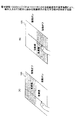
図5は、電子機器100のトップパネル120に生じさせる超音波帯の固有振動により、操作入力を行う指先に掛かる動摩擦力が変化する様子を説明する図である。図5の(A)、(B)では、利用者が指先でトップパネル120に触れながら、指をトップパネル120の奥側から手前側に矢印に沿って移動する操作入力を行っている。なお、振動のオン/オフは、振動素子140(図2及び図3参照)をオン/オフすることによって行われる。   FIG. 5 is a diagram illustrating a state in which the dynamic friction force applied to the fingertip that performs the operation input changes due to the natural vibration of the ultrasonic band generated in the top panel 120 of the electronic device 100. 5A and 5B, the user performs an operation input to move the finger along the arrow from the back side of the top panel 120 to the near side while touching the top panel 120 with the fingertip. The vibration is turned on / off by turning on / off the vibration element 140 (see FIGS. 2 and 3).

また、図5の(A)、(B)では、トップパネル120の奥行き方向において、振動がオフの間に指が触れる範囲をグレーで示し、振動がオンの間に指が触れる範囲を白く示す。   5A and 5B, in the depth direction of the top panel 120, the range in which the finger touches while the vibration is off is shown in gray, and the range in which the finger touches while the vibration is on is shown in white. .

超音波帯の固有振動は、図4に示すようにトップパネル120の全体に生じるが、図5の(A)、(B)には、利用者の指がトップパネル120の奥側から手前側に移動する間に振動のオン/オフを切り替える動作パターンを示す。   The natural vibration of the ultrasonic band occurs in the entire top panel 120 as shown in FIG. 4, but in FIGS. 5A and 5B, the user's finger is on the front side from the back side of the top panel 120. The operation pattern which switches on / off of a vibration during moving to is shown.

このため、図5の(A)、(B)では、トップパネル120の奥行き方向において、振動がオフの間に指が触れる範囲をグレーで示し、振動がオンの間に指が触れる範囲を白く示す。   For this reason, in FIGS. 5A and 5B, in the depth direction of the top panel 120, the range in which the finger touches while the vibration is off is shown in gray, and the range in which the finger touches while the vibration is on is white. Show.

図5の(A)に示す動作パターンでは、利用者の指がトップパネル120の奥側にあるときに振動がオフであり、指を手前側に移動させる途中で振動がオンになっている。   In the operation pattern shown in FIG. 5A, the vibration is turned off when the user's finger is on the back side of the top panel 120, and the vibration is turned on in the middle of moving the finger to the near side.

一方、図5の(B)に示す動作パターンでは、利用者の指がトップパネル120の奥側にあるときに振動がオンであり、指を手前側に移動させる途中で振動がオフになっている。   On the other hand, in the operation pattern shown in FIG. 5B, the vibration is turned on when the user's finger is on the back side of the top panel 120, and the vibration is turned off in the middle of moving the finger to the near side. Yes.

ここで、トップパネル120に超音波帯の固有振動を生じさせると、トップパネル120の表面と指との間にスクイーズ効果による空気層が介在し、指でトップパネル120の表面をなぞったときの動摩擦係数が低下する。   Here, when the natural vibration of the ultrasonic band is generated in the top panel 120, an air layer due to the squeeze effect is interposed between the surface of the top panel 120 and the finger, and the surface of the top panel 120 is traced with the finger. The coefficient of dynamic friction decreases.

従って、図5の(A)では、トップパネル120の奥側にグレーで示す範囲では、指先に掛かる動摩擦力は大きく、トップパネル120の手前側に白く示す範囲では、指先に掛かる動摩擦力は小さくなる。   Accordingly, in FIG. 5A, the dynamic frictional force applied to the fingertip is large in the range indicated in gray on the back side of the top panel 120, and the dynamic frictional force applied to the fingertip is small in the range indicated in white on the near side of the top panel 120. Become.

このため、図5の(A)に示すようにトップパネル120に操作入力を行う利用者は、振動がオンになると、指先に掛かる動摩擦力の低下を感知し、指先の滑り易さを知覚することになる。このとき、利用者はトップパネル120の表面がより滑らかになることにより、動摩擦力が低下するときに、トップパネル120の表面に凹部が存在するように感じる。   For this reason, as shown in FIG. 5A, the user who performs an operation input to the top panel 120 senses a decrease in the dynamic friction force applied to the fingertip and perceives the ease of slipping of the fingertip when the vibration is turned on. It will be. At this time, the user feels that a concave portion exists on the surface of the top panel 120 when the dynamic friction force decreases due to the surface of the top panel 120 becoming smoother.

一方、図5の(B)では、トップパネル120の奥前側に白く示す範囲では、指先に掛かる動摩擦力は小さく、トップパネル120の手前側にグレーで示す範囲では、指先に掛かる動摩擦力は大きくなる。   On the other hand, in FIG. 5B, the dynamic friction force applied to the fingertip is small in the range shown white on the front side of the top panel 120, and the dynamic friction force applied to the fingertip is large in the range shown in gray on the front side of the top panel 120. Become.

このため、図5の(B)に示すようにトップパネル120に操作入力を行う利用者は、振動がオフになると、指先に掛かる動摩擦力の増大を感知し、指先の滑り難さ、あるいは、引っ掛かる感じを知覚することになる。そして、指先が滑りにくくなることにより、動摩擦力が高くなるときに、トップパネル120の表面に凸部が存在するように感じる。   For this reason, as shown in FIG. 5B, the user who performs an operation input to the top panel 120 senses an increase in the dynamic friction force applied to the fingertip when the vibration is turned off, You will perceive the feeling of being caught. And when a dynamic friction force becomes high because it becomes difficult to slip a fingertip, it will feel like a convex part exists in the surface of the top panel 120. FIG.

以上より、図5の(A)と(B)の場合は、利用者は指先で凹凸を感じ取ることができる。このように人間が凹凸の知覚することは、例えば、"触感デザインのための印刷物転写法とSticky-band Illusion"(第11回計測自動制御学会システムインテグレーション部門講演会論文集 (SI2010, 仙台)____174-177, 2010-12)に記載されている。また、"Fishbone Tactile Illusion"(日本バーチャルリアリティ学会第10 回大会論文集(2005 年9 月))にも記載されている。   From the above, in the case of (A) and (B) in FIG. 5, the user can feel unevenness with the fingertip. Human perception of unevenness in this way is, for example, “Printed Transfer Method for Sticky Design and Sticky-band Illusion” (Proceedings of the 11th SICE System Integration Division Annual Conference (SI2010, Sendai) ___ 174 -177, 2010-12). It is also described in "Fishbone Tactile Illusion" (The 10th Annual Conference of the Virtual Reality Society of Japan (September 2005)).

なお、ここでは、振動のオン/オフを切り替える場合の動摩擦力の変化について説明したが、これは、振動素子140の振幅(強度)を変化させた場合も同様である。   Here, the change in the dynamic friction force when switching on / off the vibration has been described, but this is the same when the amplitude (intensity) of the vibration element 140 is changed.

次に、図6を用いて、実施の形態1の電子機器100の構成について説明する。   Next, the configuration of the electronic device 100 according to the first embodiment will be described with reference to FIG.

図6は、実施の形態1の電子機器100の構成を示す図である。   FIG. 6 is a diagram illustrating a configuration of the electronic device 100 according to the first embodiment.

電子機器100は、振動素子140、アンプ141、タッチパネル150、ドライバIC(Integrated Circuit)151、ディスプレイパネル160、ドライバIC161、電流検出部180、制御部200、正弦波発生器310、及び振幅変調器320を含む。   The electronic device 100 includes a vibration element 140, an amplifier 141, a touch panel 150, a driver IC (Integrated Circuit) 151, a display panel 160, a driver IC 161, a current detection unit 180, a control unit 200, a sine wave generator 310, and an amplitude modulator 320. including.

制御部200は、アプリケーションプロセッサ220、通信プロセッサ230、駆動制御部240、及びメモリ250を有する。制御部200は、例えば、ICチップで実現される。   The control unit 200 includes an application processor 220, a communication processor 230, a drive control unit 240, and a memory 250. The control unit 200 is realized by an IC chip, for example.

なお、ここでは、アプリケーションプロセッサ220、通信プロセッサ230、駆動制御部240、及びメモリ250が1つの制御部200によって実現される形態について説明するが、駆動制御部240は、制御部200の外部に別のICチップ又はプロセッサとして設けられていてもよい。この場合には、メモリ250に格納されているデータのうち、駆動制御部240の駆動制御に必要なデータは、メモリ250とは別のメモリに格納しておけばよい。   Here, a mode in which the application processor 220, the communication processor 230, the drive control unit 240, and the memory 250 are realized by one control unit 200 will be described. However, the drive control unit 240 is provided outside the control unit 200. It may be provided as an IC chip or a processor. In this case, among the data stored in the memory 250, data necessary for drive control of the drive control unit 240 may be stored in a memory different from the memory 250.

図6では、筐体110、トップパネル120、両面テープ130、及び基板170(図2参照)は省略する。また、ここでは、アンプ141、ドライバIC151、ドライバIC161、電流検出部180、アプリケーションプロセッサ220、駆動制御部240、メモリ250、正弦波発生器310、及び振幅変調器320について説明する。   In FIG. 6, the casing 110, the top panel 120, the double-sided tape 130, and the substrate 170 (see FIG. 2) are omitted. Here, the amplifier 141, driver IC 151, driver IC 161, current detection unit 180, application processor 220, drive control unit 240, memory 250, sine wave generator 310, and amplitude modulator 320 will be described.

アンプ141は、電流検出部180と振動素子140との間に配設されており、振幅変調器320から出力される駆動信号を増幅して振動素子140を駆動する。   The amplifier 141 is disposed between the current detection unit 180 and the vibration element 140, and amplifies the drive signal output from the amplitude modulator 320 to drive the vibration element 140.

ドライバIC151は、タッチパネル150に接続されており、タッチパネル150への操作入力があった位置を表す位置データを検出し、位置データを制御部200に出力する。この結果、位置データは、アプリケーションプロセッサ220と駆動制御部240に入力される。   The driver IC 151 is connected to the touch panel 150, detects position data indicating a position where an operation input to the touch panel 150 has been performed, and outputs the position data to the control unit 200. As a result, the position data is input to the application processor 220 and the drive control unit 240.

ドライバIC161は、ディスプレイパネル160に接続されており、アプリケーションプロセッサ220から出力される描画データをディスプレイパネル160に入力し、描画データに基づく画像をディスプレイパネル160に表示させる。これにより、ディスプレイパネル160には、描画データに基づくGUI操作部又は画像等が表示される。   The driver IC 161 is connected to the display panel 160, inputs drawing data output from the application processor 220 to the display panel 160, and causes the display panel 160 to display an image based on the drawing data. As a result, a GUI operation unit or an image based on the drawing data is displayed on the display panel 160.

電流検出部180は、振幅変調器320とアンプ141との間に設けられており、振幅変調器320からアンプ141に出力される駆動信号の電流値を検出する。電流検出部180は、検出した電流値を表す電流データをアプリケーションプロセッサ220に出力する。   The current detector 180 is provided between the amplitude modulator 320 and the amplifier 141 and detects the current value of the drive signal output from the amplitude modulator 320 to the amplifier 141. The current detection unit 180 outputs current data representing the detected current value to the application processor 220.

電流検出部180は、例えば、振幅変調器320とアンプ141を接続する配線に直列に挿入される抵抗器を用いて、抵抗器の両端間電圧を検出し、両端間電圧を抵抗器の抵抗値で除算して電流値を求めるセンサであればよい。   The current detection unit 180 detects, for example, the voltage across the resistor using a resistor inserted in series with the wiring connecting the amplitude modulator 320 and the amplifier 141, and the voltage across the resistor is used as the resistance value of the resistor. Any sensor may be used as long as the current value is obtained by dividing by.

アプリケーションプロセッサ220は、主制御部220Aを含む。主制御部220Aは、電子機器100の種々のアプリケーションを実行する処理を行う。   Application processor 220 includes a main control unit 220A. The main control unit 220A performs processing for executing various applications of the electronic device 100.

また、アプリケーションプロセッサ220は、トップパネル120の押圧を検出し、押圧による操作入力を受け付ける処理に関する構成要素として、位相補正部221、振幅比算出部222、押圧力算出部223、押圧判定部224、及び入力処理部225を含む。アプリケーションプロセッサ220は、これらの構成要素以外にも、種々のアプリケーションを実行する処理部を含むが、ここでは省略する。   In addition, the application processor 220 detects a pressing of the top panel 120 and includes components relating to a process of receiving an operation input by pressing, as a phase correction unit 221, an amplitude ratio calculation unit 222, a pressing force calculation unit 223, a press determination unit 224, And an input processing unit 225. In addition to these components, the application processor 220 includes a processing unit that executes various applications, but is omitted here.

位相補正部221は、振幅変調器320から出力される駆動信号の電圧波形を検出する。電子機器100では、トップパネル120の押圧を検出する際に、駆動信号の電圧と電流の比を用いる。駆動信号の電圧と電流の比を求める際に、電圧と電流の位相を合わせるために位相補正部221を設けている。   The phase correction unit 221 detects the voltage waveform of the drive signal output from the amplitude modulator 320. In the electronic device 100, when detecting the pressing of the top panel 120, the ratio of the voltage and current of the drive signal is used. A phase correction unit 221 is provided to match the phase of the voltage and current when determining the ratio of the voltage and current of the drive signal.

このため、位相補正部221は、駆動信号の電圧を検出して電圧の位相を補正し、駆動信号の電流の位相に合わせる。振幅変調器320から位相補正部221に入力される駆動信号は、振幅変調器320から出力される駆動信号のうちのごく微小な電流量であり、振幅変調器320からアンプ141に入力される駆動信号に影響を与えることはない。   Therefore, the phase correction unit 221 detects the voltage of the drive signal, corrects the phase of the voltage, and matches the phase of the current of the drive signal. The drive signal input from the amplitude modulator 320 to the phase correction unit 221 is a very small amount of current in the drive signal output from the amplitude modulator 320, and the drive signal input from the amplitude modulator 320 to the amplifier 141. Does not affect the signal.

位相補正部221は、例えば、駆動信号の電圧をデジタル変換するA/D(Analog to Digital)コンバータと、デジタル変換した駆動信号の電圧の位相をシフトするバッファとを含み、駆動信号の電圧の位相を補正する。位相補正部221は、駆動信号の電圧波形の位相を補正し、位相が補正された駆動信号の電圧波形を出力する。   The phase correction unit 221 includes, for example, an A / D (Analog to Digital) converter that digitally converts the voltage of the drive signal, and a buffer that shifts the phase of the voltage of the digitally converted drive signal. Correct. The phase correction unit 221 corrects the phase of the voltage waveform of the drive signal and outputs the voltage waveform of the drive signal with the phase corrected.

位相補正部221が駆動信号の電圧の位相を補正するのは、振動素子140が容量型の素子であることから、駆動信号の電圧と電流に位相差が生じる場合があるからである。   The reason why the phase correction unit 221 corrects the phase of the voltage of the drive signal is that the vibration element 140 is a capacitive element, and thus there may be a phase difference between the voltage and current of the drive signal.

位相補正部221が補正する駆動信号の電圧の位相は、実験及び/又はシミュレーション等で予め求めておけばよい。なお、駆動信号の電圧と電流と位相差が生じない場合には、アプリケーションプロセッサ220は、位相補正部221を含まなくてもよい。また、ここでは、位相補正部221が駆動信号の電圧の位相を補正する形態について説明するが、位相補正部221を電流検出部180と振幅比算出部222との間に設けて、位相補正部221が駆動信号の電流の位相を補正して、駆動信号の電圧の位相に合わせるようにしてもよい。   The phase of the voltage of the drive signal corrected by the phase correction unit 221 may be obtained in advance through experiments and / or simulations. Note that the application processor 220 may not include the phase correction unit 221 when the phase difference between the voltage and current of the drive signal does not occur. Here, a mode in which the phase correction unit 221 corrects the phase of the voltage of the drive signal will be described. However, the phase correction unit 221 is provided between the current detection unit 180 and the amplitude ratio calculation unit 222, and the phase correction unit 221 may correct the phase of the current of the drive signal to match the phase of the voltage of the drive signal.

振幅比算出部222は、電流検出部180から入力される電流データをデジタル変換するA/Dコンバータを含む。電流検出部180から入力される電流データは、アナログ値である。   The amplitude ratio calculation unit 222 includes an A / D converter that digitally converts current data input from the current detection unit 180. The current data input from the current detection unit 180 is an analog value.

振幅比算出部222は、デジタル変換された電流データが表す電流と、位相補正部221によって位相が補正された駆動信号の電圧との比を算出し、押圧力算出部223に出力する。   The amplitude ratio calculation unit 222 calculates the ratio between the current represented by the digitally converted current data and the voltage of the drive signal whose phase is corrected by the phase correction unit 221, and outputs the ratio to the pressing force calculation unit 223.

振幅比算出部222は、デジタル変換された電流データが表す電流の電流波形と、位相が補正された駆動信号の電圧の電圧波形との比を算出する。より具体的には、振幅比算出部222は、デジタル変換された電流データが表す電流の電流波形を、位相が補正された駆動信号の電圧の電圧波形で除算することにより、電流と電圧との比を算出する。なお、振幅比算出部222が算出する比は、第1の比の一例である。   The amplitude ratio calculation unit 222 calculates the ratio between the current waveform of the current represented by the digitally converted current data and the voltage waveform of the voltage of the drive signal whose phase is corrected. More specifically, the amplitude ratio calculator 222 divides the current waveform of the current represented by the digitally converted current data by the voltage waveform of the voltage of the drive signal whose phase has been corrected, so that the current and voltage Calculate the ratio. The ratio calculated by the amplitude ratio calculator 222 is an example of a first ratio.

押圧力算出部223は、振幅比算出部222によって算出される比を用いて、トップパネル120に掛かる押圧力を算出する。押圧力算出部223は、トップパネル120が押圧されていない状態における駆動信号の電流と電圧との比から、振幅比算出部222によって算出される比を減算し、減算して得る値に所定の係数を乗算することによって押圧力を算出する。   The pressing force calculation unit 223 calculates the pressing force applied to the top panel 120 using the ratio calculated by the amplitude ratio calculation unit 222. The pressing force calculation unit 223 subtracts the ratio calculated by the amplitude ratio calculation unit 222 from the ratio between the current and voltage of the drive signal when the top panel 120 is not pressed, and obtains a predetermined value to the value obtained by subtraction. The pressing force is calculated by multiplying the coefficient.

押圧力算出部223によって算出される押圧力は、押圧度合の一例である。トップパネル120が押圧されていない状態における駆動信号の電流と電圧との比は、第2の比の一例である。なお、押圧力の具体的な算出方法と、所定の係数とについては、後述する。   The pressing force calculated by the pressing force calculation unit 223 is an example of the pressing degree. The ratio between the current and voltage of the drive signal when the top panel 120 is not pressed is an example of the second ratio. A specific method for calculating the pressing force and the predetermined coefficient will be described later.

押圧判定部224は、押圧力算出部223によって算出される押圧力が第1閾値以上になると、トップパネル120が押圧された(押圧が開始した)と判定し、押圧判定フラグをオンに設定する。   When the pressing force calculated by the pressing force calculation unit 223 exceeds the first threshold value, the pressing determination unit 224 determines that the top panel 120 is pressed (pressing has started), and sets the pressing determination flag to ON. .

トップパネル120が押圧されたと押圧判定部224が判定することは、押圧による入力内容が確定したことを意味する。押圧判定フラグとは、押圧が行われているかどうかを表すフラグである。押圧判定フラグをオンに設定することは、押圧判定フラグの値が'1'に設定されることである。   The determination by the pressing determination unit 224 that the top panel 120 has been pressed means that the input content by pressing has been determined. The pressure determination flag is a flag indicating whether or not pressure is being performed. Setting the pressure determination flag to ON means that the value of the pressure determination flag is set to “1”.

また、押圧判定部224は、押圧力算出部223によって算出される押圧力が第1閾値よりも低い第2閾値以下になると、押圧が終了したと判定する。この場合には、押圧判定部224は、押圧判定フラグをオフに設定する。押圧判定フラグをオフに設定することは、押圧判定フラグの値が'0'に設定されることである。押圧判定部224は、押圧判定フラグを入力処理部225に出力する。   In addition, when the pressing force calculated by the pressing force calculation unit 223 is equal to or lower than a second threshold value that is lower than the first threshold value, the pressing determination unit 224 determines that the pressing is finished. In this case, the press determination unit 224 sets the press determination flag to off. Setting the pressure determination flag to OFF means that the value of the pressure determination flag is set to “0”. The press determination unit 224 outputs a press determination flag to the input processing unit 225.

すなわち、押圧判定部224は、押圧力算出部223によって算出される押圧力に基づいて、トップパネル120が押圧されたかどうかを判定する。   That is, the pressing determination unit 224 determines whether the top panel 120 is pressed based on the pressing force calculated by the pressing force calculation unit 223.

なお、第1閾値と第2閾値を表すデータは、メモリ250に格納しておけばよい。   Note that data representing the first threshold value and the second threshold value may be stored in the memory 250.

入力処理部225は、トップパネル120が押圧されたと押圧判定部224が判定すると、トップパネル120の押圧によって行われた入力内容を判定し、判定結果を表すデータを主制御部220Aに出力する。この結果、主制御部220Aは、押圧によって行われる入力内容に応じた処理を行う。   When the pressing determination unit 224 determines that the top panel 120 has been pressed, the input processing unit 225 determines the input content made by pressing the top panel 120 and outputs data representing the determination result to the main control unit 220A. As a result, the main control unit 220A performs processing according to the input content performed by pressing.

例えば、GUI操作部が電話をかけるGUIボタンであり、電話をかけるGUIボタンが押圧された場合には、入力処理部225は、押圧による入力内容は、電話をかける操作であると判定し、電話をかける操作が行われたことを表す信号を主制御部220Aに伝送する。この結果、主制御部220Aは、電話をかける処理を行う。   For example, when the GUI operation unit is a GUI button for making a call and the GUI button for making a call is pressed, the input processing unit 225 determines that the input content by the press is an operation for making a call, A signal indicating that the operation of applying is performed is transmitted to the main controller 220A. As a result, the main control unit 220A performs a process for making a call.

通信プロセッサ230は、電子機器100が3G(Generation)、4G(Generation)、LTE(Long Term Evolution)、WiFi等の通信を行うために必要な処理を実行する。   The communication processor 230 executes processing necessary for the electronic device 100 to perform communication such as 3G (Generation), 4G (Generation), LTE (Long Term Evolution), and WiFi.

駆動制御部240は、振幅データを振幅変調器320に出力する。振幅データは、振動素子140の駆動に用いる駆動信号の強度を調整するための振幅値を表すデータであり、駆動信号の振幅(電圧)を表す。   The drive control unit 240 outputs the amplitude data to the amplitude modulator 320. The amplitude data is data representing an amplitude value for adjusting the intensity of the drive signal used for driving the vibration element 140, and represents the amplitude (voltage) of the drive signal.

振幅値は、位置データと振動が開始してからの経過時間に応じて設定される。なお、ここでは一例として、振幅値が位置データと振動が開始してからの経過時間とに応じて設定される形態について説明するが、利用者の指先の移動に応じて振幅値を変化させてもよい。   The amplitude value is set according to the position data and the elapsed time from the start of vibration. Here, as an example, a description will be given of a mode in which the amplitude value is set according to the position data and the elapsed time from the start of vibration, but the amplitude value is changed according to the movement of the user's fingertip. Also good.

また、実施の形態1の電子機器100は、利用者の指先がトップパネル120に触れているときと、利用者の指先がトップパネル120の表面に沿って移動しているときにトップパネル120を振動させる。   In addition, the electronic device 100 according to the first embodiment uses the top panel 120 when the user's fingertip touches the top panel 120 and when the user's fingertip moves along the surface of the top panel 120. Vibrate.

利用者の指先がトップパネル120の表面に沿って移動したときにトップパネル120を振動させると、指先に掛かる動摩擦力が変化する。   If the top panel 120 is vibrated when the user's fingertip moves along the surface of the top panel 120, the dynamic friction force applied to the fingertip changes.

また、電子機器100は、操作入力を行う指先の位置が、振動を発生させるべき所定の領域内にある場合に、振幅データを振幅変調器320に出力する。   In addition, electronic device 100 outputs amplitude data to amplitude modulator 320 when the position of the fingertip where the operation input is performed is within a predetermined region where vibration is to be generated.

操作入力を行う指先の位置が振動を発生させるべき所定の領域内にあるかどうかは、操作入力を行う指先の位置が、振動を発生させるべき所定の領域の内部にあるか否かに基づいて判定される。   Whether or not the position of the fingertip that performs the operation input is within a predetermined region where the vibration is to be generated is based on whether or not the position of the fingertip that performs the operation input is within the predetermined region where the vibration is to be generated. Determined.

ここで、ディスプレイパネル160に表示するGUI操作部、画像を表示する領域、又は、ページ全体を表す領域等のディスプレイパネル160上における位置は、当該領域を表す領域データによって特定される。領域データは、すべてのアプリケーションにおいて、ディスプレイパネル160に表示されるすべてのGUI操作部、画像を表示する領域、又は、ページ全体を表す領域について存在する。   Here, the position on the display panel 160 such as a GUI operation unit to be displayed on the display panel 160, a region for displaying an image, or a region representing the entire page is specified by region data representing the region. In all applications, the area data exists for all GUI operation units displayed on the display panel 160, areas for displaying images, or areas representing the entire page.

このため、操作入力を行う指先の位置が、振動を発生させるべき所定の領域内にあるかどうかを判定する際には、電子機器100が起動しているアプリケーションの種類が関係することになる。アプリケーションの種類により、ディスプレイパネル160の表示が異なるからである。   For this reason, when determining whether or not the position of the fingertip for performing the operation input is within a predetermined region where vibration is to be generated, the type of application in which the electronic device 100 is activated is related. This is because the display on the display panel 160 differs depending on the type of application.

また、アプリケーションの種類により、トップパネル120の表面に触れた指先を移動させる操作入力の種類が異なるからである。トップパネル120の表面に触れた指先を移動させる操作入力の種類としては、例えば、GUI操作部を操作する際には、所謂フリック操作がある。フリック操作は、指先をトップパネル120の表面に沿って、はじく(スナップする)ように比較的短い距離移動させる操作である。   This is because the type of operation input for moving the fingertip touching the surface of the top panel 120 differs depending on the type of application. As a type of operation input for moving the fingertip touching the surface of the top panel 120, for example, when operating the GUI operation unit, there is a so-called flick operation. The flick operation is an operation of moving a fingertip along a surface of the top panel 120 for a relatively short distance so as to be repelled (snapped).

また、ページを捲る場合には、例えば、スワイプ操作を行う。スワイプ操作は、指先をトップパネル120の表面に沿って掃くように比較的長い距離移動させる操作である。スワイプ操作は、ページを捲る場合の他に、例えば、写真を捲る場合に行われる。また、GUI操作部によるスライダー(図1のスライダー102B参照)をスライドさせる場合には、スライダーをドラッグするドラッグ操作が行われる。   Further, when turning a page, for example, a swipe operation is performed. The swipe operation is an operation of moving a fingertip along a relatively long distance so as to sweep along the surface of the top panel 120. The swipe operation is performed, for example, when turning a photo in addition to turning the page. Further, when sliding the slider (see the slider 102B in FIG. 1) by the GUI operation unit, a drag operation for dragging the slider is performed.

ここで一例として挙げるフリック操作、スワイプ操作、及びドラッグ操作のように、トップパネル120の表面に触れた指先を移動させる操作入力は、アプリケーションによる表示の種類によって使い分けられる。このため、操作入力を行う指先の位置が、振動を発生させるべき所定の領域内にあるかどうかを判定する際には、電子機器100が起動しているアプリケーションの種類が関係することになる。   The operation input for moving the fingertip that touches the surface of the top panel 120, such as a flick operation, a swipe operation, and a drag operation, which are given here as examples, is selectively used depending on the type of display by the application. For this reason, when determining whether or not the position of the fingertip for performing the operation input is within a predetermined region where vibration is to be generated, the type of application in which the electronic device 100 is activated is related.

駆動制御部240は、領域データを用いて、ドライバIC151から入力される位置データが表す位置が、振動を発生させるべき所定の領域の内部にあるか否かを判定する。   The drive control unit 240 determines whether or not the position represented by the position data input from the driver IC 151 is within a predetermined area where vibration is to be generated, using the area data.

アプリケーションの種類を表すデータと、操作入力が行われるGUI操作部等を表す領域データと、振動パターンを表すパターンデータとを関連付けたデータは、メモリ250に格納されている。   Data that associates data representing the type of application, area data representing a GUI operation unit or the like on which an operation input is performed, and pattern data representing a vibration pattern is stored in the memory 250.

駆動制御部240は、操作入力を行う指先の位置が、振動を発生させるべき所定の領域内にある場合に、位置データに対応する振幅値を表す振幅データをメモリ250から読み出して、振幅変調器320に出力する。   The drive control unit 240 reads amplitude data representing an amplitude value corresponding to the position data from the memory 250 when the position of the fingertip that performs the operation input is within a predetermined region where vibration is to be generated, and the amplitude modulator To 320.

メモリ250は、振幅値を表す振幅データと、振動を生じさせる領域を表す領域データとの関係を表すデータを格納する。また、メモリ250は、アプリケーションの種類を表すデータと、操作入力が行われるGUI操作部等を表す領域データと、振動パターンを表すパターンデータとを関連付けたデータを格納する。   The memory 250 stores data representing the relationship between the amplitude data representing the amplitude value and the region data representing the region causing the vibration. In addition, the memory 250 stores data in which data representing the type of application, area data representing a GUI operation unit or the like where an operation input is performed, and pattern data representing a vibration pattern are associated with each other.

また、メモリ250は、アプリケーションプロセッサ220がアプリケーションの実行に必要とするデータ及びプログラム、及び、通信プロセッサ230が通信処理に必要とするデータ及びプログラム等を格納する。   In addition, the memory 250 stores data and programs necessary for the application processor 220 to execute an application, data and programs necessary for the communication processor 230 for communication processing, and the like.

正弦波発生器310は、トップパネル120を固有振動数で振動させるための駆動信号を生成するのに必要な正弦波を発生させる。例えば、トップパネル120を38.6[kHz]の固有振動数fで振動させる場合は、正弦波の周波数は、38.6[kHz]となる。   The sine wave generator 310 generates a sine wave necessary for generating a drive signal for vibrating the top panel 120 at a natural frequency. For example, when the top panel 120 is vibrated at a natural frequency f of 38.6 [kHz], the frequency of the sine wave is 38.6 [kHz].

正弦波発生器310が発生する正弦波信号は、超音波帯の固有振動を発生させる駆動信号の元になる交流の基準信号であり、一定の周波数と一定の位相を有する。正弦波発生器310は、超音波帯の正弦波信号を振幅変調器320に入力する。   The sine wave signal generated by the sine wave generator 310 is an AC reference signal that is a source of the drive signal that generates the natural vibration of the ultrasonic band, and has a constant frequency and a constant phase. The sine wave generator 310 inputs an ultrasonic band sine wave signal to the amplitude modulator 320.

なお、ここでは、正弦波信号を発生する正弦波発生器310を用いる形態について説明するが、正弦波信号ではなくてもよい。例えば、クロックの立ち上がりと立ち下がりの波形を鈍らせたような波形の信号を用いてもよい。このため、超音波帯の交流信号を発生する信号発生器を正弦波発生器310の代わりに用いてもよい。   In addition, although the form using the sine wave generator 310 which generates a sine wave signal is demonstrated here, it may not be a sine wave signal. For example, a signal having a waveform in which the rising and falling waveforms of the clock are blunted may be used. For this reason, a signal generator that generates an ultrasonic wave AC signal may be used instead of the sine wave generator 310.

振幅変調器320は、駆動制御部240から入力される振幅データを用いて、正弦波発生器310から入力される正弦波信号の振幅を変調して駆動信号を生成する。振幅変調器320は、正弦波発生器310から入力される超音波帯の正弦波信号の振幅のみを変調し、周波数及び位相は変調せずに、駆動信号を生成する。   The amplitude modulator 320 generates a drive signal by modulating the amplitude of the sine wave signal input from the sine wave generator 310 using the amplitude data input from the drive control unit 240. The amplitude modulator 320 modulates only the amplitude of the sine wave signal in the ultrasonic band input from the sine wave generator 310, and generates the drive signal without modulating the frequency and phase.

このため、振幅変調器320が出力する駆動信号は、正弦波発生器310から入力される超音波帯の正弦波信号の振幅のみを変調した超音波帯の正弦波信号である。なお、振幅データがゼロの場合は、駆動信号の振幅はゼロになる。これは、振幅変調器320が駆動信号を出力しないことと等しい。   Therefore, the drive signal output from the amplitude modulator 320 is an ultrasonic band sine wave signal obtained by modulating only the amplitude of the ultrasonic band sine wave signal input from the sine wave generator 310. Note that when the amplitude data is zero, the amplitude of the drive signal is zero. This is equivalent to the amplitude modulator 320 not outputting a drive signal.

図7は、電流検出部180を示す図である。   FIG. 7 is a diagram illustrating the current detection unit 180.

電流検出部180は、抵抗器181と、電流検出IC(Integrated Circuit)182とを有する。抵抗器181は、振幅変調器320とアンプ141を接続する配線に直列に挿入されている。電流検出IC182は、差動アンプと(Analog to Digital Converter)とを有し、抵抗器181の両端間電圧を検出し、両端間電圧を抵抗器181の抵抗値で除算して電流値を求める。求めた電流値を表すデータは、アプリケーションプロセッサ220に伝送される。   The current detection unit 180 includes a resistor 181 and a current detection IC (Integrated Circuit) 182. The resistor 181 is inserted in series with the wiring connecting the amplitude modulator 320 and the amplifier 141. The current detection IC 182 has a differential amplifier and (Analog to Digital Converter), detects the voltage across the resistor 181, and divides the voltage across the resistor 181 to obtain the current value. Data representing the obtained current value is transmitted to the application processor 220.

図8は、押圧の有無と駆動信号の電圧及び電流との関係を示す図である。   FIG. 8 is a diagram showing the relationship between the presence or absence of pressing and the voltage and current of the drive signal.

図8の(A1)と(B1)に断面で示す電子機器100には、駆動信号の電流を検出する電流検出部180と、駆動制御部240、正弦波発生器310、及び振幅変調器320を纏めた交流源とを示す。図8の(A1)は押圧無しの場合であり、利用者の指先はトップパネル120から離れている。図8の(B1)は押圧有りの場合であり、利用者の指先はトップパネル120をZ軸負方向に押圧している。なお、断面で示す電子機器100のトップパネル120に示す波形は、超音波帯の固有振動を模式的に示している。   The electronic device 100 shown in cross section in (A1) and (B1) of FIG. 8 includes a current detection unit 180 that detects a current of a drive signal, a drive control unit 240, a sine wave generator 310, and an amplitude modulator 320. A summary of the AC sources. FIG. 8A1 shows a case where no pressure is applied, and the user's fingertip is separated from the top panel 120. (B1) of FIG. 8 is a case where there is a press, and the user's fingertip presses the top panel 120 in the negative Z-axis direction. In addition, the waveform shown on the top panel 120 of the electronic device 100 shown in cross section schematically shows the natural vibration of the ultrasonic band.

押圧無しの場合には、図8の(A1)に示すように、電子機器100のトップパネル120には、設計値通りの振幅の超音波帯の固有振動が発生する。このときの駆動信号の電圧Vp1と電流Ip1は、図8の(A2)と(A3)に示す通りである。   In the case of no pressing, as shown in FIG. 8A1, the natural vibration of the ultrasonic band having the amplitude as the design value is generated on the top panel 120 of the electronic device 100. The voltage Vp1 and current Ip1 of the drive signal at this time are as shown in (A2) and (A3) of FIG.

これに対して、押圧有りの場合には、図8の(B1)に示すように、電子機器100のトップパネル120に生じる超音波帯の固有振動の振幅は、押圧無しの場合よりも小さくなる。利用者の指によって押圧されているからである。   On the other hand, when the pressure is applied, as shown in FIG. 8B1, the amplitude of the natural vibration of the ultrasonic band generated on the top panel 120 of the electronic device 100 is smaller than that without the pressure. . This is because it is pressed by the user's finger.

このときの駆動信号の電圧Vp2は、図8の(B2)に示すように、押圧無しの場合の電圧Vp1と等しいが、駆動信号の電流Ip2は、図8の(B3)に示すように、押圧無しの場合の電流Ip1よりも減少し、振幅が小さくなる。   The voltage Vp2 of the drive signal at this time is equal to the voltage Vp1 in the case of no pressing as shown in (B2) of FIG. 8, but the current Ip2 of the drive signal is as shown in (B3) of FIG. The current is smaller than the current Ip1 when no pressure is applied, and the amplitude becomes smaller.

振動素子140に流れる電流は、振動素子140の振動の振幅に略比例しており、トップパネル120が押圧されて超音波帯の固有振動の振幅が小さくなることは、振動素子140の振動の振幅が小さくなることを意味するからである。   The current flowing through the vibration element 140 is substantially proportional to the vibration amplitude of the vibration element 140, and the amplitude of the natural vibration of the ultrasonic band is reduced by pressing the top panel 120. This is because it means that becomes smaller.

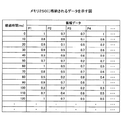
図9は、押圧力と、駆動信号の電流及び電圧の比との関係を示す図である。図9において、横軸は駆動信号の周波数(Hz)であり、縦軸は、駆動信号の電流Ip及び電圧Vpの比Ip/Vpである。図9に示す特性は、実験で得られたものである。   FIG. 9 is a diagram illustrating the relationship between the pressing force and the ratio of the current and voltage of the drive signal. In FIG. 9, the horizontal axis represents the frequency (Hz) of the drive signal, and the vertical axis represents the ratio Ip / Vp between the current Ip and the voltage Vp of the drive signal. The characteristics shown in FIG. 9 are obtained through experiments.

押圧力が0g(ゼログラム)である場合には、比Ip/Vpは、共振周波数である38.6kHz(f1)で最大値(約0.15)になる。押圧力が100gである場合には、比Ip/Vpは、38.6kHzで約0.09に低下し、押圧力が200gである場合には、比Ip/Vpは、38.6kHzで約0.085に低下する。押圧によって電流値が減るためである。   When the pressing force is 0 g (zero gram), the ratio Ip / Vp becomes the maximum value (about 0.15) at the resonance frequency of 38.6 kHz (f1). When the pressing force is 100 g, the ratio Ip / Vp drops to about 0.09 at 38.6 kHz, and when the pressing force is 200 g, the ratio Ip / Vp is about 0 at 38.6 kHz. To 0.085. This is because the current value is reduced by pressing.

なお、押圧によってトップパネル120の振動モードに多少の変化が生じるため、押圧力が100gと200gの場合には、比Ip/Vpの最大値が得られる共振周波数が少し高周波数側にシフトする。   In addition, since a slight change occurs in the vibration mode of the top panel 120 due to the pressing, when the pressing force is 100 g and 200 g, the resonance frequency at which the maximum value of the ratio Ip / Vp is obtained is slightly shifted to the high frequency side.

図10は、図9に示す実験結果を押圧力と比Ip/Vpとの関係で纏めた図である。図10に示す比Ip/Vpは、トップパネル120の設計上の共振周波数である38.6kHz(f1)における値である。   FIG. 10 is a diagram summarizing the experimental results shown in FIG. 9 in relation to the pressing force and the ratio Ip / Vp. The ratio Ip / Vp shown in FIG. 10 is a value at 38.6 kHz (f1), which is the designed resonance frequency of the top panel 120.

図10に示すように、押圧力の増大に伴い、比Ip/Vpが低下していることが分かる。   As shown in FIG. 10, it can be seen that the ratio Ip / Vp decreases as the pressing force increases.

図11は、電子機器100の操作の様子を示す図である。図12は、図11のように操作された場合における、押圧力、駆動信号の振幅、及び比Ip/Vpを示す図である。なお、図11には、電子機器100のトップパネル120、タッチパネル150、及びディスプレイパネル160をトップパネル120側から見た状態を示す。ここでは、一例として、振幅がA1で一定の駆動信号を用いて振動素子140を振動する場合について説明する。   FIG. 11 is a diagram illustrating how the electronic device 100 is operated. FIG. 12 is a diagram showing the pressing force, the amplitude of the drive signal, and the ratio Ip / Vp when operated as shown in FIG. FIG. 11 illustrates a state in which the top panel 120, the touch panel 150, and the display panel 160 of the electronic device 100 are viewed from the top panel 120 side. Here, as an example, a case where the vibration element 140 is vibrated using a constant drive signal with an amplitude of A1 will be described.

図11に示すように、ディスプレイパネル160にGUI操作部としてのアイコン191Aが表示されている状態において、利用者がトップパネル120の位置P1からスワイプ操作を開始し、位置P2でアイコン191Aの左端に到達し、アイコン191Aの中央(位置P3)でアイコン191Aを押圧し、押圧した後に位置P3で指先をトップパネル120から離したとする。また、振動素子140(図6参照)は、アイコン191Aの表示領域内で操作入力が行われた場合に駆動されることとする。   As shown in FIG. 11, in the state where the icon 191A as the GUI operation unit is displayed on the display panel 160, the user starts the swipe operation from the position P1 of the top panel 120, and at the position P2, the user moves to the left end of the icon 191A. Assume that the icon 191A is pressed at the center (position P3) of the icon 191A, and the fingertip is released from the top panel 120 at the position P3 after being pressed. The vibration element 140 (see FIG. 6) is driven when an operation input is performed within the display area of the icon 191A.

このような場合には、図12に示すように押圧が検出される。時刻t11において、利用者がトップパネル120の位置P1に触れると、位置P1はアイコン191Aの表示領域の外であるため、振動素子140は駆動されず、駆動信号の振幅はゼロである。   In such a case, pressing is detected as shown in FIG. When the user touches the position P1 of the top panel 120 at time t11, since the position P1 is outside the display area of the icon 191A, the vibration element 140 is not driven, and the amplitude of the drive signal is zero.

時刻t12において、スワイプ操作を行っている利用者の指先がトップパネル120の位置P2に到達すると、位置P2はアイコン191Aの表示領域内であるため、振動素子140が駆動され、駆動信号の振幅はA1になる。   When the fingertip of the user performing the swipe operation reaches the position P2 of the top panel 120 at time t12, the position P2 is within the display area of the icon 191A, so that the vibration element 140 is driven, and the amplitude of the drive signal is It becomes A1.

スワイプ操作を行っているときは、指先はトップパネル120の表面に軽く触れているため、押圧力はP1である。P1はごく小さい押圧力である。また、振動素子140が駆動されることによって振動素子140には電圧と電流が供給されるため、時刻t12で比Ip/VpはR1となる。   When performing the swipe operation, the fingertip is lightly touching the surface of the top panel 120, so the pressing force is P1. P1 is a very small pressing force. Further, since the voltage and current are supplied to the vibration element 140 by driving the vibration element 140, the ratio Ip / Vp becomes R1 at time t12.

時刻t13において、スワイプ操作を行っている利用者の指先がトップパネル120の位置P3に到達し、利用者が指先を移動させずに押圧を開始する。   At time t13, the fingertip of the user who is performing the swipe operation reaches the position P3 of the top panel 120, and the user starts pressing without moving the fingertip.

操作入力の位置(指先の位置)が停止していても、アイコン191Aの表示領域内にあるため、駆動信号の振幅はA1に保持される。   Even if the position of the operation input (the position of the fingertip) is stopped, the drive signal amplitude is held at A1 because it is within the display area of the icon 191A.

また、押圧力が増大するため、振動素子140に供給される電流が減少するため、時刻t13で比Ip/VpはR1から低下し始める。   Further, since the pressing force increases and the current supplied to the vibration element 140 decreases, the ratio Ip / Vp starts to decrease from R1 at time t13.

時刻t14において、押圧力が第1閾値に到達する。第1閾値は、押圧判定部224が押圧の開始を判定する場合に用いる閾値である。時刻t14では、操作入力の位置(指先の位置)が停止していても、アイコン191Aの表示領域内にあるため、駆動信号の振幅はA1に保持される。   At time t14, the pressing force reaches the first threshold value. The first threshold is a threshold used when the pressing determination unit 224 determines the start of pressing. At time t14, even if the position of the operation input (the position of the fingertip) is stopped, the drive signal amplitude is maintained at A1 because it is within the display area of the icon 191A.

また、時刻t14では、比Ip/Vpは第3閾値に到達する。第3閾値は、第1閾値に対応する比Ip/Vpを表す。   At time t14, the ratio Ip / Vp reaches the third threshold value. The third threshold represents a ratio Ip / Vp corresponding to the first threshold.

時刻t14の直後に押圧力は最大値を取り、利用者は押圧力を徐々に減らし始める。   Immediately after time t14, the pressing force takes the maximum value, and the user starts to gradually decrease the pressing force.

そして、時刻t15において、押圧力が第2閾値まで低下する。第2閾値は、押圧判定部224が押圧の終了を判定する場合に用いる閾値である。時刻t15では、操作入力の位置(指先の位置)が停止していても、アイコン191Aの表示領域内にあるため、駆動信号の振幅はA1に保持される。   At time t15, the pressing force decreases to the second threshold value. The second threshold value is a threshold value used when the pressing determination unit 224 determines the end of pressing. At time t15, even if the position of the operation input (the position of the fingertip) is stopped, the drive signal amplitude is held at A1 because it is within the display area of the icon 191A.

また、時刻t15では、比Ip/Vpは第4閾値に到達する。第4閾値は、第2閾値に対応する比Ip/Vpを表す。押圧力と比Ip/Vpは反比例の関係にあるため、第4閾値は、第3閾値よりも高い値を有する。   At time t15, the ratio Ip / Vp reaches the fourth threshold value. The fourth threshold represents the ratio Ip / Vp corresponding to the second threshold. Since the pressing force and the ratio Ip / Vp are inversely proportional, the fourth threshold value is higher than the third threshold value.

時刻t16において、利用者の指先が位置P3においてトップパネル120から離れると、押圧力はゼロになる。また、指先がトップパネル120から離れることによって振動素子140が停止され、駆動信号の振幅はゼロになる。   When the user's fingertip moves away from the top panel 120 at the position P3 at time t16, the pressing force becomes zero. Further, when the fingertip is separated from the top panel 120, the vibration element 140 is stopped, and the amplitude of the drive signal becomes zero.

以上の動作は一例に過ぎないが、このようにして電子機器100は、押圧を検出する。なお、ここでは、アイコン191Aを操作する場合の電子機器100の動作について説明したが、アイコン191B〜191Gを操作する場合も電子機器100は同様に動作を行う。   Although the above operation is only an example, the electronic device 100 detects the press in this way. Although the operation of the electronic device 100 when operating the icon 191A has been described here, the electronic device 100 performs the same operation when operating the icons 191B to 191G.

次に、図13乃至図15を用いて、メモリ250にデータについて説明する。   Next, data in the memory 250 will be described with reference to FIGS.

図13乃至図15は、メモリ250に格納されるデータを示す図である。   13 to 15 are diagrams showing data stored in the memory 250.

図13に示すデータは、アプリケーションの種類を表すデータと、操作入力が行われるGUI操作部等が表示される領域の座標値を表す領域データ(X座標の範囲、Y座標の範囲)と、振動パターンを表すパターンデータとを関連付けたデータである。   The data shown in FIG. 13 includes data representing the type of application, area data representing the coordinate value of the area in which the GUI operation unit or the like where the operation input is performed, and the vibrations. This is data associated with pattern data representing a pattern.

換言すれば、図13に示すデータは、振動素子140を振動させる領域(以下、対象領域と称す)の種類と、領域データ(X座標の範囲、Y座標の範囲)と、振動パターンを表すパターンデータとを関連付けたデータである。   In other words, the data shown in FIG. 13 is a pattern representing the type of region (hereinafter referred to as a target region) in which the vibration element 140 is vibrated, region data (X coordinate range, Y coordinate range), and a vibration pattern. Data associated with data.

図13では、アプリケーションの種類を表すデータとして、アプリケーションID(Identification)を示す。また、対象領域の種類として、対象領域1〜対象領域7を示す。また、対象領域の領域データとして、操作入力が行われるGUI操作部等が表示される領域のX座標の範囲とY座標の範囲を示す。また、振動パターンを表すパターンデータとして、P1〜P4を示す。   In FIG. 13, an application ID (Identification) is shown as data representing the type of application. Further, the target area 1 to the target area 7 are shown as types of the target area. In addition, as the area data of the target area, an X coordinate range and a Y coordinate range of an area in which a GUI operation unit or the like where an operation input is performed are displayed. P1 to P4 are shown as pattern data representing the vibration pattern.

図14に示すデータは、振動を開始してからの経過時間(ms(ミリ秒))と、振幅データとを含む。図12には、振幅がA1で一定の駆動信号を用いて振動素子140を振動する場合について説明したが、図14には、振動を開始してからの経過時間に応じて振幅が変化する振幅データを示す。   The data shown in FIG. 14 includes elapsed time (ms (milliseconds)) since the start of vibration and amplitude data. FIG. 12 illustrates the case where the vibration element 140 is vibrated using a constant drive signal with an amplitude of A1, but FIG. 14 illustrates an amplitude whose amplitude changes according to the elapsed time from the start of vibration. Data is shown.

ここでは、一例として、経過時間は10ms毎に0msから120msまでを示す。振幅データは、駆動信号の振幅(電圧)を表し、振動パターンP1〜P4のそれぞれについてデータが用意されている。   Here, as an example, the elapsed time is from 0 ms to 120 ms every 10 ms. The amplitude data represents the amplitude (voltage) of the drive signal, and data is prepared for each of the vibration patterns P1 to P4.

図14に示す振幅データを駆動制御部240がメモリ250から読み出して振幅変調器320に出力することにより、時間の経過とともに、正弦波発生器310から出力される超音波帯の正弦波信号の振幅が振幅変調器320によって変調される。   The drive control unit 240 reads the amplitude data shown in FIG. 14 from the memory 250 and outputs the amplitude data to the amplitude modulator 320, so that the amplitude of the sine wave signal of the ultrasonic band output from the sine wave generator 310 with the passage of time. Is modulated by the amplitude modulator 320.

図15は、押圧力算出部223が比Ip/Vpを用いて押圧力を算出する場合に用いるテーブル形式のデータの一例を示す。押圧力が0g(ゼログラム)である場合の比Ip0/Vp0から、押圧力が掛かったときの比Ip/Vpを減算した比の差分(Ip0/Vp0−Ip/Vp)と、押圧変換係数PFとを関連付けたデータである。   FIG. 15 shows an example of table format data used when the pressing force calculation unit 223 calculates the pressing force using the ratio Ip / Vp. The ratio difference (Ip0 / Vp0−Ip / Vp) obtained by subtracting the ratio Ip / Vp when the pressing force is applied from the ratio Ip0 / Vp0 when the pressing force is 0 g (zero gram), the pressing conversion coefficient PF, Is the data associated with.

押圧力が0g(ゼログラム)である場合の比Ip0/Vp0から、押圧力が掛かったときの比Ip/Vpを減算した比の差分(Ip0/Vp0−Ip/Vp)を用いるのは、次のような理由による。すなわち、押圧力が0gのときの比Ip0/Vp0を基準にして、押圧力が掛かることによって比Ip/Vpが変化した差分を求めれば、トップパネル120に掛かる押圧力に対応する比Ip/Vpの変化分を求めることができるからである。   The ratio difference (Ip0 / Vp0−Ip / Vp) obtained by subtracting the ratio Ip / Vp when the pressing force is applied from the ratio Ip0 / Vp0 when the pressing force is 0 g (zero gram) is used as follows. For reasons like this. That is, if a difference in which the ratio Ip / Vp is changed by applying the pressing force is obtained on the basis of the ratio Ip0 / Vp0 when the pressing force is 0 g, the ratio Ip / Vp corresponding to the pressing force applied to the top panel 120 is obtained. This is because the amount of change can be obtained.

押圧変換係数PFを用いると、押圧力Fmは次式(3)で求めることができる。
Fm=PF×(Ip0/Vp0−Ip/Vp) (3)
すなわち、押圧変換係数PFは、比の差分(Ip0/Vp0−Ip/Vp)から押圧力Fmを求めるための係数である。
When the pressing conversion coefficient PF is used, the pressing force Fm can be obtained by the following equation (3).
Fm = PF × (Ip0 / Vp0−Ip / Vp) (3)
That is, the pressing conversion coefficient PF is a coefficient for obtaining the pressing force Fm from the difference in the ratio (Ip0 / Vp0−Ip / Vp).

図15に示す押圧変換係数PFは、押圧力に対してトップパネル120が線形的に変形する場合の値である。このため、比の差分(Ip0/Vp0−Ip/Vp)が増大しても、押圧変換係数PFは一定値(25)に設定されている。押圧変換係数PFの値は、トップパネル120の寸法及び/又はヤング率等の値に応じて、最適な値に設定すればよい。   The pressing conversion coefficient PF shown in FIG. 15 is a value when the top panel 120 is linearly deformed with respect to the pressing force. For this reason, even if the ratio difference (Ip0 / Vp0−Ip / Vp) increases, the pressing conversion coefficient PF is set to a constant value (25). The value of the pressing conversion coefficient PF may be set to an optimal value according to the size of the top panel 120 and / or the Young's modulus.

なお、押圧力が0g(ゼログラム)である場合の比Ip0/Vp0を表すデータもメモリ250に格納しておけばよい。   Data indicating the ratio Ip0 / Vp0 when the pressing force is 0 g (zero gram) may be stored in the memory 250.

図16は、アプリケーションプロセッサ220が実行する処理を示すフローチャートである。   FIG. 16 is a flowchart showing processing executed by the application processor 220.

アプリケーションプロセッサ220は、位置データを検出すると、処理を開始する(スタート)。すなわち、ドライバIC151から主制御部220Aに位置データが入力されると処理が開始される。   When the application processor 220 detects the position data, it starts processing (start). That is, when position data is input from the driver IC 151 to the main controller 220A, the process is started.

アプリケーションプロセッサ220は、位置データが表す座標が対象領域内にあるかどうかを判定する(ステップS1)。より具体的には、主制御部220Aは、位置データが表す座標が、図13に示す対象領域の領域データに含まれるかどうかを判定する。   The application processor 220 determines whether or not the coordinates represented by the position data are within the target area (step S1). More specifically, main controller 220A determines whether or not the coordinates represented by the position data are included in the area data of the target area shown in FIG.

アプリケーションプロセッサ220は、振動素子140が対象領域内にある(S1:YES)と判定すると、対象領域に関連付けられた振動パターンに対応する振幅データを図14に示すデータから読み出して、駆動制御部240から出力させる(ステップS2)。ステップS2の処理は、主制御部220Aが実行すればよい。   If the application processor 220 determines that the vibration element 140 is in the target region (S1: YES), the application processor 220 reads out amplitude data corresponding to the vibration pattern associated with the target region from the data shown in FIG. (Step S2). The main control unit 220A may execute the process of step S2.

アプリケーションプロセッサ220は、駆動信号の電流値と電圧値を取得する(ステップS3)。ここで、電流値と電圧値は、例えば、駆動信号の1周期の期間にわたって取得すればよい。駆動信号の周波数は、正弦波信号の周波数と等しいため、正弦波信号の1周期の期間にわたって電流値と電圧値を取得すればよい。   The application processor 220 acquires the current value and voltage value of the drive signal (step S3). Here, the current value and the voltage value may be acquired over a period of one cycle of the drive signal, for example. Since the frequency of the drive signal is equal to the frequency of the sine wave signal, the current value and the voltage value may be acquired over a period of one cycle of the sine wave signal.

ステップS3では、電流値を表す電流波形データと、電圧値を表す電圧波形データとが取得される。電流波形データと電圧波形データは、正弦波の式で表される。ステップS3の処理のうち、電流値の取得は、振幅比算出部222が実行すればよく、電圧値の取得は、位相補正部221が実行すればよい。   In step S3, current waveform data representing a current value and voltage waveform data representing a voltage value are acquired. The current waveform data and the voltage waveform data are represented by a sine wave formula. In the process of step S3, the current value acquisition may be executed by the amplitude ratio calculation unit 222, and the voltage value acquisition may be executed by the phase correction unit 221.

なお、電流値と電圧値を取得する期間は、駆動信号の1周期の期間に限らず、駆動信号の1周期の期間よりも長くても短くてもよい。   Note that the period for acquiring the current value and the voltage value is not limited to one period of the drive signal, and may be longer or shorter than the period of one period of the drive signal.

アプリケーションプロセッサ220は、ステップS3で取得した電圧波形データの位相を補正する(ステップS4)。ステップS4の処理は、位相補正部221が実行すればよい。ステップS4の処理により、電流波形データの位相と、電圧波形データの位相とが合わせられる。位相が補正された電圧波形データは、振幅比算出部222に入力される。   The application processor 220 corrects the phase of the voltage waveform data acquired in step S3 (step S4). The process of step S4 may be executed by the phase correction unit 221. By the processing in step S4, the phase of the current waveform data and the phase of the voltage waveform data are matched. The voltage waveform data with the phase corrected is input to the amplitude ratio calculation unit 222.

アプリケーションプロセッサ220は、電流波形データを電圧波形データで除算することにより、比Ip/Vpを算出する(ステップS5)。ステップS5の処理は、振幅比算出部222が電流波形データを表す式を電圧波形データを表す式で除算することによって実行すればよい。   The application processor 220 calculates the ratio Ip / Vp by dividing the current waveform data by the voltage waveform data (step S5). The processing in step S5 may be executed by the amplitude ratio calculation unit 222 dividing the equation representing the current waveform data by the equation representing the voltage waveform data.

アプリケーションプロセッサ220は、ステップS5で算出した比Ip/Vpと、押圧力が0g(ゼログラム)である場合の比Ip0/Vp0とを用いて、比Ip0/Vp0から比Ip/Vpを減算した比の差分(Ip0/Vp0−Ip/Vp)を求め、押圧力Fmを算出(ステップS6)。   The application processor 220 uses the ratio Ip / Vp calculated in step S5 and the ratio Ip0 / Vp0 when the pressing force is 0 g (zero gram) to subtract the ratio Ip / Vp from the ratio Ip0 / Vp0. The difference (Ip0 / Vp0−Ip / Vp) is obtained, and the pressing force Fm is calculated (step S6).

ステップS5の処理は、押圧力算出部223が押圧変換係数PFを含むデータ(図15参照)を用いて、式(3)に従って算出することによって実行すればよい。   The process of step S5 may be executed by the pressing force calculation unit 223 calculating according to the equation (3) using data including the pressing conversion coefficient PF (see FIG. 15).

アプリケーションプロセッサ220は、ステップS6で算出した押圧力Fmが第1閾値(図12参照)以上であるかどうかを判定する(ステップS7)。ステップS7の処理は、押圧判定部224がメモリ250に格納されている第1閾値を読み出して押圧力Fmと比較することによって実行すればよい。   The application processor 220 determines whether or not the pressing force Fm calculated in step S6 is greater than or equal to the first threshold (see FIG. 12) (step S7). The process of step S7 may be executed by the pressing determination unit 224 reading out the first threshold stored in the memory 250 and comparing it with the pressing force Fm.

アプリケーションプロセッサ220は、押圧力Fmが第1閾値(図12参照)以上である(S7:YES)と判定すると、押圧判定フラグをオンに設定する(ステップS8)。ステップS8の処理は、押圧判定部224が実行すればよい。   If the application processor 220 determines that the pressing force Fm is greater than or equal to the first threshold (see FIG. 12) (S7: YES), the application processor 220 sets the pressing determination flag to on (step S8). The process of step S8 may be performed by the press determination unit 224.

アプリケーションプロセッサ220は、主制御部220Aに押圧判定フラグをオンに設定したことを通知する(ステップS9)。ステップS9の処理は、押圧判定部224が実行すればよい。主制御部220Aに押圧判定フラグをオンに設定したことを通知することは、押圧判定部224が押圧判定フラグをオフに設定したことを上位アプリケーションに通知することと同義である。   The application processor 220 notifies the main control unit 220A that the pressure determination flag has been set to ON (step S9). The process of step S9 may be executed by the press determination unit 224. Notifying the main control unit 220A that the pressure determination flag has been set to ON is synonymous with notifying the host application that the pressure determination unit 224 has set the pressure determination flag to OFF.

アプリケーションプロセッサ220は、操作入力が行われているかどうかを判定する(ステップS10)。操作入力が行われていなければ、押圧検出を行う必要がなくなるからである。ステップS10の処理は、主制御部220Aが、位置データの有無を判定することによって実行すればよい。   The application processor 220 determines whether an operation input has been performed (step S10). This is because if no operation input is performed, there is no need to detect pressing. The process of step S10 may be executed when the main control unit 220A determines the presence / absence of position data.

アプリケーションプロセッサ220は、操作入力が行われている(S10:YES)と判定すると、フローをステップS1にリターンする。引き続き押圧検出を行うためである。   If the application processor 220 determines that an operation input has been made (S10: YES), the flow returns to step S1. This is because the pressure is continuously detected.

一方、アプリケーションプロセッサ220は、操作入力が行われていない(S10:NO)と判定すると、一連の処理を終了する(エンド)。操作入力が行われていなければ、押圧検出を行う必要がなくなるからである。   On the other hand, when the application processor 220 determines that no operation input has been performed (S10: NO), the series of processing ends (end). This is because if no operation input is performed, there is no need to detect pressing.

アプリケーションプロセッサ220は、ステップS7で押圧力Fmが第1閾値(図12参照)以上ではない(S7:NO)と判定すると、押圧判定フラグがオンに設定されているかどうかを判定する(ステップS11)。ステップS11の処理は、押圧判定部224が実行すればよい。   If the application processor 220 determines in step S7 that the pressing force Fm is not equal to or greater than the first threshold value (see FIG. 12) (S7: NO), the application processor 220 determines whether the pressing determination flag is set to on (step S11). . The process of step S11 may be executed by the press determination unit 224.

アプリケーションプロセッサ220は、押圧判定フラグがオンに設定されている(S11:YES)と判定すると、押圧力が第2閾値(図12参照)以下であるかどうかを判定する(ステップS12)。押圧が終了しているかどうかを判定するためである。ステップS12の処理は、押圧判定部224が実行すればよい。   If the application processor 220 determines that the pressing determination flag is set to ON (S11: YES), the application processor 220 determines whether the pressing force is equal to or less than the second threshold (see FIG. 12) (step S12). This is to determine whether or not the pressing is finished. The process of step S12 may be performed by the press determination unit 224.

アプリケーションプロセッサ220は、押圧力が第2閾値以下である(S12:YES)と判定すると、押圧は終了したと判定し、押圧判定フラグをオフに設定する(ステップS13)。押圧は終了しているからである。   If the application processor 220 determines that the pressing force is equal to or less than the second threshold (S12: YES), the application processor 220 determines that the pressing has ended, and sets the pressing determination flag to OFF (step S13). This is because the pressing is finished.

アプリケーションプロセッサ220は、主制御部220Aに押圧判定フラグをオフに設定したことを通知する(ステップS14)。ステップS14の処理は、押圧判定部224が実行すればよい。主制御部220Aに押圧判定フラグをオフに設定したことを通知することは、押圧判定部224が押圧判定フラグをオフに設定したことを上位アプリケーションに通知することと同義である。   The application processor 220 notifies the main control unit 220A that the pressure determination flag has been set to OFF (step S14). The press determination unit 224 may execute the process of step S14. Notifying the main control unit 220A that the pressure determination flag is set to off is synonymous with notifying the host application that the pressure determination unit 224 has set the pressure determination flag to off.

なお、アプリケーションプロセッサ220は、ステップS14の処理を終えると、フローをステップS10に進行させる。   In addition, the application processor 220 advances a flow to step S10, after finishing the process of step S14.

アプリケーションプロセッサ220は、押圧判定フラグがオンに設定されていない(S11:NO)と判定すると、フローをステップS10に進行させる。押圧が行われていないため、操作入力の有無を確認するためである。   If the application processor 220 determines that the pressure determination flag is not set to ON (S11: NO), the application processor 220 advances the flow to step S10. This is to confirm the presence or absence of an operation input since no pressing is performed.

アプリケーションプロセッサ220は、ステップS12で押圧力が第2閾値以下ではない(S12:NO)と判定すると、フローをステップS10に進行させる。操作入力の有無を確認するためである。   If the application processor 220 determines in step S12 that the pressing force is not equal to or less than the second threshold (S12: NO), the application processor 220 advances the flow to step S10. This is to confirm the presence or absence of operation input.

アプリケーションプロセッサ220は、位置データが表す座標が対象領域内にない(S1:NO)と判定すると、振動素子140をオフにする(ステップS15)。操作入力の位置が対象領域内にない場合は、振動素子140を振動しないためである。   If the application processor 220 determines that the coordinates represented by the position data are not within the target area (S1: NO), the application processor 220 turns off the vibration element 140 (step S15). This is because the vibration element 140 is not vibrated when the position of the operation input is not within the target region.

アプリケーションプロセッサ220は、押圧判定フラグがオンであるかどうかを判定する(ステップS16)。位置データが表す座標が対象領域内にないときに、押圧判定フラグがオンである場合には、押圧判定フラグをオフに設定する必要があるからである。   The application processor 220 determines whether or not the pressure determination flag is on (step S16). This is because when the coordinates represented by the position data are not within the target area and the pressure determination flag is on, it is necessary to set the pressure determination flag to off.

アプリケーションプロセッサ220は、押圧判定フラグがオンである(S16:YES)と判定すると、押圧判定フラグをオフにする(ステップS17)。操作入力の位置が対象領域内になければ、押圧による入力を行うことができる位置ではないため、押圧判定フラグをオフにすることとしたものである。   If the application processor 220 determines that the pressure determination flag is on (S16: YES), the application processor 220 turns off the pressure determination flag (step S17). If the position of the operation input is not within the target area, it is not a position where input by pressing is possible, and therefore the pressing determination flag is turned off.

アプリケーションプロセッサ220は、主制御部220Aに押圧判定フラグをオフに設定したことを通知する(ステップS18)。ステップS18の処理は、押圧判定部224が実行すればよい。主制御部220Aに押圧判定フラグをオフに設定したことを通知することは、押圧判定部224が押圧判定フラグをオフに設定したことを上位アプリケーションに通知することと同義である。   The application processor 220 notifies the main control unit 220A that the pressure determination flag has been set to OFF (step S18). The process of step S18 may be executed by the press determination unit 224. Notifying the main control unit 220A that the pressure determination flag is set to off is synonymous with notifying the host application that the pressure determination unit 224 has set the pressure determination flag to off.

アプリケーションプロセッサ220は、押圧判定フラグがオンではない(S16:NO)と判定すると、フローをステップS10に進行させる。押圧は行われていないため、操作入力の有無を確認するためである。   If the application processor 220 determines that the pressure determination flag is not on (S16: NO), the application processor 220 advances the flow to step S10. This is to confirm the presence or absence of an operation input because no pressing is performed.

以上により、一連の処理が終了する。   Thus, a series of processing ends.

実施の形態1の電子機器100によれば、振動素子140を駆動している場合に、利用者がトップパネル120を押圧しているのかどうかを検出するができる。このような押圧検出を可能にしているのは、振動素子140に供給される電流Ipと、電圧Vpの比Ip/Vpを監視し、押圧による電流Ipの変化を検出しているからである。   According to the electronic device 100 of the first embodiment, it is possible to detect whether the user is pressing the top panel 120 when the vibration element 140 is driven. The reason why such pressing is detected is that the ratio Ip / Vp between the current Ip supplied to the vibration element 140 and the voltage Vp is monitored to detect a change in the current Ip due to pressing.

振動素子140が駆動されているときに利用者がトップパネル120を押圧すると、駆動信号の振幅(電圧)が一定であっても、振動素子140に供給される電流量が低下する。また、このような状態で駆動信号の振幅(電圧)を増大又は減少させると、振動素子140に供給される電流量も増大又は減少するが、トップパネル120が押圧されていない場合に比べると、振動素子140に供給される電流量は減少している。   When the user presses the top panel 120 while the vibration element 140 is driven, the amount of current supplied to the vibration element 140 decreases even if the amplitude (voltage) of the drive signal is constant. Further, when the amplitude (voltage) of the drive signal is increased or decreased in such a state, the amount of current supplied to the vibration element 140 is also increased or decreased. However, compared to the case where the top panel 120 is not pressed, The amount of current supplied to the vibration element 140 is decreasing.

実施の形態1では、このような押圧に伴う電流量の変化を検出するために、電圧Vpの比Ip/Vpを監視し、押圧による電流Ipの変化を検出する。   In the first embodiment, in order to detect such a change in the amount of current due to the pressing, the voltage Vp ratio Ip / Vp is monitored to detect a change in the current Ip due to the pressing.

従って、実施の形態1によれば、使い勝手の良好な電子機器100、及び、押圧検出プログラムを提供することができる。   Therefore, according to the first embodiment, it is possible to provide the electronic device 100 with good usability and the press detection program.

また、以上では、比の差分(Ip0/Vp0−Ip/Vp)に基づいて算出する押圧力を第1閾値又は第2閾値と比較することによって押圧判定を行う形態について説明したが、電流Ipと電圧Vpの比Ip/Vpを所定の閾値と比較することによって押圧が行われているかどうかを判定してもよい。この場合には、押圧力を求めることはできないが、押圧が行われているかどうかを判定することはできる。   Moreover, although the above demonstrated the form which performs a pressure determination by comparing the pressing force calculated based on the ratio difference (Ip0 / Vp0-Ip / Vp) with the 1st threshold value or the 2nd threshold value, It may be determined whether or not pressing is performed by comparing the ratio Ip / Vp of the voltage Vp with a predetermined threshold. In this case, the pressing force cannot be obtained, but it can be determined whether or not the pressing is performed.

また、以上では、押圧力に対してトップパネル120が線形的に変形する場合の押圧変換係数PF(図15参照)を用いる形態について説明したが、トップパネル120が非線形的に変形する場合には押圧変換係数PFを図17に示すように設定すればよい。   In the above description, the form using the pressure conversion coefficient PF (see FIG. 15) when the top panel 120 is linearly deformed with respect to the pressing force has been described. However, when the top panel 120 is nonlinearly deformed. What is necessary is just to set the press conversion coefficient PF as shown in FIG.

図17は、実施の形態1の第1変形例による、比の差分(Ip0/Vp0−Ip/Vp)と押圧変換係数PFとを関連付けたデータを示す図である。   FIG. 17 is a diagram illustrating data in which a ratio difference (Ip0 / Vp0−Ip / Vp) and a pressure conversion coefficient PF are associated with each other according to the first modification of the first embodiment.

図17に示す押圧変換係数PFは、押圧力に対してトップパネル120の非線形的に変形する場合の値である。ここで、非線形的に変形する場合とは、押圧力の増大に応じて、トップパネル120が変形しにくくなる場合をいう。   The pressing conversion coefficient PF shown in FIG. 17 is a value when the top panel 120 deforms nonlinearly with respect to the pressing force. Here, the case of non-linear deformation refers to a case where the top panel 120 becomes difficult to deform in accordance with an increase in pressing force.

トップパネル120が押圧力の増大に応じて変形しにくくなる場合には、比の差分(Ip0/Vp0−Ip/Vp)の増大に対して、押圧変換係数PFが増大するようにすればよい。図17には、15から82まで段階的に増大する押圧変換係数PFを示す。   When the top panel 120 becomes difficult to deform as the pressing force increases, the pressing conversion coefficient PF may be increased as the ratio difference (Ip0 / Vp0−Ip / Vp) increases. FIG. 17 shows the pressure conversion coefficient PF that increases stepwise from 15 to 82. FIG.

押圧変換係数PFの値は、トップパネル120の寸法及び/又はヤング率等の値に応じて、最適な値に設定すればよい。   The value of the pressing conversion coefficient PF may be set to an optimal value according to the size of the top panel 120 and / or the Young's modulus.

また、以上では、一例として、電子機器100がタッチパネルを入力操作部とする、スマートフォン端末機、又は、タブレット型コンピュータである形態について説明した。また、電子機器100は、例えば、携帯情報端末機、又は、ATMのように特定の場所に設置されて利用される機器であってもよいと説明した。   In the above description, as an example, the electronic device 100 has been described as a smartphone terminal or a tablet computer using a touch panel as an input operation unit. In addition, the electronic device 100 has been described as being, for example, a portable information terminal or a device that is installed and used in a specific place such as an ATM.

ここでは、図18及び図19を用いて、実施の形態1の第2変形例として、車載型の形態について説明する。   Here, a vehicle-mounted type will be described as a second modification of the first embodiment with reference to FIGS. 18 and 19.

図18は、車両10の室内内のドライバーズシート11の周りを示す図である。車両10の室内には、ドライバーズシート11、ダッシュボード12、ステアリングホイール13、センターコンソール14、ドアの内張15等が配設される。なお、車両10は、例えば、ハイブリッド自動車(HV(Hybrid Vehicle))、電気自動車(EV(Electric Vehicle))、ガソリンエンジン車、ディーゼルエンジン車、燃料電池車(FCV(Fuel Cell Vehicle))、水素自動車等であればよい。   FIG. 18 is a view showing the periphery of the driver's seat 11 in the vehicle 10. A driver's seat 11, a dashboard 12, a steering wheel 13, a center console 14, a door lining 15 and the like are disposed in the vehicle 10. The vehicle 10 is, for example, a hybrid vehicle (HV (Hybrid Vehicle)), an electric vehicle (EV (Electric Vehicle)), a gasoline engine vehicle, a diesel engine vehicle, a fuel cell vehicle (FCV (Fuel Cell Vehicle)), or a hydrogen vehicle. Etc.

実施の形態1の電子機器100を入力装置として、例えば、ダッシュボード12の中央部12A、ステアリングホイール13のスポーク部13A、センターコンソール14のシフトレバー16の周囲14A、及びドアの内張15の凹部15A等に配設することができる。   Using electronic device 100 of the first embodiment as an input device, for example, central portion 12A of dashboard 12, spoke portion 13A of steering wheel 13, periphery 14A of shift lever 16 of center console 14, and recess of door lining 15 15A or the like.

また、図18には示さないが、実施の形態の電子機器100は、車両10の外側に入力装置として設けられてもよい。例えば、ドアハンドルの周囲に設けて、電子錠の操作部として用いてもよい。   Although not shown in FIG. 18, electronic device 100 according to the embodiment may be provided as an input device outside vehicle 10. For example, it may be provided around a door handle and used as an operation part of an electronic lock.

図19は、実施の形態1の第2変形例の電子機器100Aを示す平面図である。   FIG. 19 is a plan view showing an electronic device 100A according to a second modification of the first embodiment.

電子機器100Aは、一例として、空調コントローラとして用いられる。電子機器100Aは、例えば、図18に示す車両10の室内のダッシュボード12の中央部12A等に配設される。   The electronic device 100A is used as an air conditioning controller as an example. The electronic device 100A is disposed, for example, in the central portion 12A of the dashboard 12 in the room of the vehicle 10 shown in FIG.

図19に示すように、電子機器100Aは、筐体111、振動素子140A、タッチパネル150A、ディスプレイパネル160Aを含む。電子機器100Aは、図1乃至図3及び図6に示す電子機器100と同様であるが、ここでは上述以外の構成要素を省略する。   As illustrated in FIG. 19, the electronic device 100A includes a housing 111, a vibration element 140A, a touch panel 150A, and a display panel 160A. The electronic device 100A is the same as the electronic device 100 shown in FIGS. 1 to 3 and 6, but the components other than those described above are omitted here.

ディスプレイパネル160Aには、空調コントローラとして、操作部162A1、162A2、162A3、162A4、162A5、162A6、162A7、162A8と、表示部122Aの画像が表示されている。   The display panel 160A displays an operation unit 162A1, 162A2, 162A3, 162A4, 162A5, 162A6, 162A7, 162A8 and an image of the display unit 122A as an air conditioning controller.

操作部162A1、162A2(FAN)は、風量を調整(増大又は減少)する操作部である。操作部162A3(A/A)はエアコンのオン/オフを選択する操作部である。操作部162A4は内気循環モードを選択する操作部である。操作部162A5(mode)は、空調のモード選択を行う操作部である。操作部162A6は、デフロスターのオン/オフを選択する操作部である。操作部162A7、162A8(TEMP)は、空調の設定温度を調整(上昇又は低下)する操作部である。   The operation units 162A1 and 162A2 (FAN) are operation units that adjust (increase or decrease) the air volume. The operation unit 162A3 (A / A) is an operation unit that selects ON / OFF of the air conditioner. The operation unit 162A4 is an operation unit that selects the inside air circulation mode. The operation unit 162A5 (mode) is an operation unit that performs air-conditioning mode selection. The operation unit 162A6 is an operation unit that selects on / off of the defroster. The operation units 162A7 and 162A8 (TEMP) are operation units that adjust (increase or decrease) the set temperature of the air conditioning.

このような操作部162A1、162A2、162A3、162A4、162A5、162A6、162A7、162A8は、GUI操作部として表示されている。   Such operation units 162A1, 162A2, 162A3, 162A4, 162A5, 162A6, 162A7, and 162A8 are displayed as GUI operation units.

また、表示部122Aには、設定温度、風量、及び風向が表示されている。   In addition, the set temperature, the air volume, and the wind direction are displayed on the display unit 122A.

操作部162A1、162A2、162A3、162A4、162A5、162A6、162A7、162A8を押圧すると、それぞれ、風量の調整、エアコンのオン/オフ、内気循環モードの選択、空調のモード選択、デフロスターのオン/オフ、設定温度の調整を行うことができる。   When the operation unit 162A1, 162A2, 162A3, 162A4, 162A5, 162A6, 162A7, 162A8 is pressed, the air volume is adjusted, the air conditioner is turned on / off, the inside air circulation mode is selected, the air conditioning mode is selected, the defroster is turned on / off, The set temperature can be adjusted.

なお、ここでは、空調コントローラとして用いられる電子機器100Aについて説明したが、電子機器100Aは、ナビゲーション用の画面、オーディオコントローラ用の画面等を表示して、ナビゲーション又はオーディオの操作を行えるようにしてもよい。   Here, the electronic device 100A used as the air conditioning controller has been described, but the electronic device 100A displays a navigation screen, an audio controller screen, and the like so that navigation or audio operations can be performed. Good.

また、表示部122Aを液晶パネルで実現し、操作部162A1、162A2、162A3、162A4、162A5、162A6、162A7、162A8をトップパネル120の裏面に印刷し、ディスプレイパネル160を省略してもよい。   Alternatively, the display unit 122A may be realized by a liquid crystal panel, and the operation units 162A1, 162A2, 162A3, 162A4, 162A5, 162A6, 162A7, and 162A8 may be printed on the back surface of the top panel 120, and the display panel 160 may be omitted.

このような場合には、電子機器100Aは、ディスプレイパネル160を含まないことになる。操作部162A1、162A2、162A3、162A4、162A5、162A6、162A7、162A8がそれぞれ印刷された領域をタッチパネル150の座標と関連付けて、それぞれの操作を判定すればよい。   In such a case, the electronic device 100A does not include the display panel 160. The operation units 162A1, 162A2, 162A3, 162A4, 162A5, 162A6, 162A7, and 162A8 may be associated with the coordinates of the touch panel 150 and the respective operations may be determined.

このようにディスプレイパネル160を含まない電子機器100Aを車両10の各部に設けてもよい。   As described above, the electronic device 100 </ b> A that does not include the display panel 160 may be provided in each part of the vehicle 10.

図20は、第3変形例の電子機器100Bを示す図である。電子機器100Bは、ノートブック型のPC(Personal Computer:パーソナルコンピュータ)である。   FIG. 20 is a diagram illustrating an electronic apparatus 100B according to a third modification. The electronic device 100B is a notebook PC (Personal Computer).

PC100Bは、ディスプレイパネル160B1とタッチパッド160B2を含む。   The PC 100B includes a display panel 160B1 and a touch pad 160B2.

図21は、第3変形例の電子機器100Bのタッチパッド160B2の断面を示す図である。図21に示す断面は、図3に示すA−A矢視断面に対応する断面である。図21では図3と同様に直交座標系であるXYZ座標系を定義する。   FIG. 21 is a diagram illustrating a cross-section of the touch pad 160B2 of the electronic device 100B according to the third modification. The cross section shown in FIG. 21 is a cross section corresponding to the AA arrow cross section shown in FIG. In FIG. 21, an XYZ coordinate system which is an orthogonal coordinate system is defined as in FIG.

タッチパッド160B2は、図3に示す電子機器100から、ディスプレイパネル160を取り除いた構成を有する。   The touch pad 160B2 has a configuration in which the display panel 160 is removed from the electronic device 100 illustrated in FIG.

図20に示すようなPCとしての電子機器100Bにおいて、タッチパッド160B2への操作入力に応じて、振動素子140のオン/オフを切り替えることによってトップパネル120に超音波帯の固有振動を発生させれば、図3に示す電子機器100と同様に、タッチパッド160B2への操作入力の移動量に応じて、利用者の指先に触感を通じて操作感を提供することができる。   In the electronic device 100B as a PC as shown in FIG. 20, the natural vibration of the ultrasonic band can be generated in the top panel 120 by switching the vibration element 140 on / off in response to an operation input to the touch pad 160B2. For example, similarly to the electronic device 100 illustrated in FIG. 3, an operational feeling can be provided to the user's fingertip through a tactile sensation according to the amount of operation input to the touch pad 160B2.

また、ディスプレイパネル160B1の裏面に振動素子140を設けておけば、図3に示す電子機器100と同様に、ディスプレイパネル160B1への操作入力の移動量に応じて、利用者の指先に触感を通じて操作感を提供することができる。この場合は、ディスプレイパネル160B1の代わりに、図3に示す電子機器100を設ければよい。   In addition, if the vibration element 140 is provided on the back surface of the display panel 160B1, the user can operate the fingertip of the user through the tactile sensation according to the amount of operation input to the display panel 160B1 as in the electronic device 100 shown in FIG. A feeling can be provided. In this case, the electronic device 100 illustrated in FIG. 3 may be provided instead of the display panel 160B1.

<実施の形態2>
図22は、実施の形態2の電子機器100Cの構成を示す図である。
<Embodiment 2>
FIG. 22 is a diagram illustrating a configuration of an electronic device 100C according to the second embodiment.

実施の形態2の電子機器100Cは、比の差分(Ip0/Vp0−Ip/Vp)の求め方が実施の形態1の電子機器100と異なる。以下、相違点を中心に説明する。   The electronic device 100C of the second embodiment differs from the electronic device 100 of the first embodiment in how to obtain the ratio difference (Ip0 / Vp0−Ip / Vp). Hereinafter, the difference will be mainly described.

電子機器100Cは、振動素子140、アンプ141、タッチパネル150、ドライバIC(Integrated Circuit)151、ディスプレイパネル160、ドライバIC161、電流検出部180、制御部200C、正弦波発生器310、及び振幅変調器320を含む。   The electronic device 100C includes a vibration element 140, an amplifier 141, a touch panel 150, a driver IC (Integrated Circuit) 151, a display panel 160, a driver IC 161, a current detection unit 180, a control unit 200C, a sine wave generator 310, and an amplitude modulator 320. including.

電子機器100Cは、制御部200Cのアプリケーションプロセッサ220Cの構成が異なる以外は、実施の形態1の電子機器100と同様である。このため、実施の形態1の電子機器100と同様の構成要素には同一符号を付し、その説明を省略する。   The electronic device 100C is the same as the electronic device 100 of the first embodiment except that the configuration of the application processor 220C of the control unit 200C is different. For this reason, the same code | symbol is attached | subjected to the component similar to the electronic device 100 of Embodiment 1, and the description is abbreviate | omitted.

制御部200Cは、アプリケーションプロセッサ220C、通信プロセッサ230、駆動制御部240、及びメモリ250を有する。制御部200Cは、例えば、ICチップで実現される。   The control unit 200C includes an application processor 220C, a communication processor 230, a drive control unit 240, and a memory 250. The control unit 200C is realized by an IC chip, for example.

アプリケーションプロセッサ220Cは、主制御部220Aを含む。主制御部220Aは、電子機器100Cの種々のアプリケーションを実行する処理を行う。   The application processor 220C includes a main control unit 220A. The main control unit 220A performs processing for executing various applications of the electronic device 100C.

また、アプリケーションプロセッサ220Cは、トップパネル120の押圧を検出し、押圧による操作入力を受け付ける処理に関する構成要素として、振幅比算出部222、押圧力算出部223、押圧判定部224、入力処理部225、及び電流振幅算出部226を含む。   In addition, the application processor 220 </ b> C detects the pressing of the top panel 120, and includes components related to processing for receiving an operation input by pressing, such as an amplitude ratio calculation unit 222, a pressing force calculation unit 223, a pressure determination unit 224, an input processing unit 225, And a current amplitude calculator 226.

アプリケーションプロセッサ220Cは、実施の形態1の位相補正部221の代わりに、電流振幅算出部226を設けたものである。また、アプリケーションプロセッサ220Cの振幅比算出部222には、電流振幅算出部226から電流振幅データが入力されるとともに、駆動制御部240から振幅データが入力される。振幅データはデジタルデータである。   The application processor 220C includes a current amplitude calculation unit 226 instead of the phase correction unit 221 of the first embodiment. In addition, current amplitude data is input from the current amplitude calculation unit 226 and amplitude data is input from the drive control unit 240 to the amplitude ratio calculation unit 222 of the application processor 220C. The amplitude data is digital data.

アプリケーションプロセッサ220Cは、これらの構成要素以外にも、種々のアプリケーションを実行する処理部を含むが、ここでは省略する。   In addition to these components, the application processor 220C includes a processing unit that executes various applications, but is omitted here.

電流振幅算出部226は、電流検出部180によって検出される駆動信号の電流を検出し、電流の振幅を求める。電流の振幅とは、電流検出部180によって検出される超音波帯の交流電流の振幅(最大値)である。   The current amplitude calculator 226 detects the current of the drive signal detected by the current detector 180 and obtains the current amplitude. The amplitude of the current is the amplitude (maximum value) of the alternating current in the ultrasonic band detected by the current detection unit 180.

電流振幅算出部226は、例えば、ピークホールド回路を用いて、電流の振幅を検出することによって実現することができる。また、電流振幅算出部226は、このような構成に限られず、例えば、積分等の演算処理を行って電流の振幅を求める演算部で実現してもよい。   The current amplitude calculation unit 226 can be realized, for example, by detecting the current amplitude using a peak hold circuit. In addition, the current amplitude calculation unit 226 is not limited to such a configuration, and may be realized by, for example, a calculation unit that performs calculation processing such as integration to obtain the current amplitude.

電流振幅算出部226は、電流の振幅を表す電流振幅データを振幅比算出部222に出力する。電流の振幅は、デジタル値である。   The current amplitude calculation unit 226 outputs current amplitude data representing the current amplitude to the amplitude ratio calculation unit 222. The amplitude of the current is a digital value.

振幅比算出部222には、電流振幅算出部226によって算出される電流振幅データと、駆動制御部240が出力する振幅データとが入力される。   The amplitude ratio calculation unit 222 receives the current amplitude data calculated by the current amplitude calculation unit 226 and the amplitude data output from the drive control unit 240.

振幅比算出部222は、電流振幅データが表す電流の振幅Ipと、振幅データが表す振幅(電圧)Vpとの比Ip/Vpを算出し、押圧力算出部223に出力する。   The amplitude ratio calculation unit 222 calculates a ratio Ip / Vp between the current amplitude Ip represented by the current amplitude data and the amplitude (voltage) Vp represented by the amplitude data, and outputs the ratio Ip / Vp to the pressing force calculation unit 223.

なお、押圧力算出部223、押圧判定部224、及び入力処理部225の処理内容は、実施の形態1と同様である。   The processing contents of the pressing force calculation unit 223, the pressing determination unit 224, and the input processing unit 225 are the same as those in the first embodiment.

図23は、アプリケーションプロセッサ220Cが実行する処理を示すフローチャートである。図23に示すフローチャートは、図16に示すフローチャートのステップS3、S4、S5をそれぞれステップS23、S24、S25に置き換えたものである。従って、ステップS1、S2、S6〜S18については、図16に示すフローチャートと同様である。このため、以下では、相違点を中心に説明する。   FIG. 23 is a flowchart showing processing executed by the application processor 220C. The flowchart shown in FIG. 23 is obtained by replacing steps S3, S4, and S5 of the flowchart shown in FIG. 16 with steps S23, S24, and S25, respectively. Accordingly, steps S1, S2, and S6 to S18 are the same as those in the flowchart shown in FIG. For this reason, below, it demonstrates focusing on a difference.

アプリケーションプロセッサ220Cは、ステップS2の処理が終了すると、駆動信号の電流値を取得する(ステップS23)。ここで、電流値は、電流振幅算出部226が電流振幅データを算出するのに必要な時間にわたって取得すればよい。電流振幅データを算出するのに必要な時間は、例えば、駆動信号の1周期の期間より短くてよい。   When the process of step S2 ends, the application processor 220C acquires the current value of the drive signal (step S23). Here, the current value may be acquired over a time necessary for the current amplitude calculation unit 226 to calculate the current amplitude data. The time required to calculate the current amplitude data may be shorter than the period of one cycle of the drive signal, for example.

ステップS23では、駆動信号の電流値が取得される。ステップS23の処理は、電流振幅算出部226が実行すればよい。   In step S23, the current value of the drive signal is acquired. The current amplitude calculation unit 226 may execute the process of step S23.

アプリケーションプロセッサ220Cは、ステップS23で取得した駆動信号の電流値から電流振幅データを算出する(ステップS24)。ステップS24の処理は、電流振幅算出部226が実行すればよい。電流振幅データは、振幅比算出部222に入力される。   The application processor 220C calculates current amplitude data from the current value of the drive signal acquired in step S23 (step S24). The current amplitude calculation unit 226 may execute the process of step S24. The current amplitude data is input to the amplitude ratio calculation unit 222.

アプリケーションプロセッサ220Cは、電流振幅データが表す電流の振幅Ipを振幅データが表す振幅(電圧)Vpで除算することにより、比Ip/Vpを算出する(ステップS25)。   The application processor 220C calculates the ratio Ip / Vp by dividing the current amplitude Ip represented by the current amplitude data by the amplitude (voltage) Vp represented by the amplitude data (step S25).

アプリケーションプロセッサ220Cは、ステップS25の処理が終了すると、フローをステップS6に進行させる。ステップS6以降は、実施の形態1と同様である。   When the process of step S25 ends, the application processor 220C advances the flow to step S6. Step S6 and subsequent steps are the same as those in the first embodiment.

実施の形態2の電子機器100Cによれば、振動素子140を駆動している場合に、利用者がトップパネル120を押圧しているのかどうかを検出するができる。このような押圧検出を可能にしているのは、振動素子140に供給される電流Ipと、振幅データが表す振幅(電圧)Vpの比Ip/Vpを監視し、押圧による電流Ipの変化を検出しているからである。   According to electronic device 100C of the second embodiment, when driving vibration element 140, it is possible to detect whether the user is pressing top panel 120 or not. This pressure detection is made possible by monitoring the ratio Ip / Vp between the current Ip supplied to the vibration element 140 and the amplitude (voltage) Vp represented by the amplitude data, and detecting a change in the current Ip due to the pressure. Because it is.

振動素子140が駆動されているときに利用者がトップパネル120を押圧すると、駆動信号の振幅(電圧)が一定であっても、振動素子140に供給される電流量が低下する。また、このような状態で駆動信号の振幅(電圧)を増大又は減少させると、振動素子140に供給される電流量も増大又は減少するが、トップパネル120が押圧されていない場合に比べると、振動素子140に供給される電流量は減少している。   When the user presses the top panel 120 while the vibration element 140 is driven, the amount of current supplied to the vibration element 140 decreases even if the amplitude (voltage) of the drive signal is constant. Further, when the amplitude (voltage) of the drive signal is increased or decreased in such a state, the amount of current supplied to the vibration element 140 is also increased or decreased. However, compared to the case where the top panel 120 is not pressed, The amount of current supplied to the vibration element 140 is decreasing.

実施の形態2では、このような押圧に伴う電流量の変化を検出するために、振幅データが表す振幅(電圧)Vpの比Ip/Vpを監視し、押圧による電流Ipの変化を検出する。   In the second embodiment, in order to detect such a change in the amount of current due to pressing, the ratio Ip / Vp of the amplitude (voltage) Vp represented by the amplitude data is monitored, and the change in the current Ip due to pressing is detected.

従って、実施の形態2によれば、使い勝手の良好な電子機器100C、及び、押圧検出プログラムを提供することができる。   Therefore, according to the second embodiment, it is possible to provide a user-friendly electronic device 100C and a press detection program.

また、実施の形態2の電子機器100Cでは、駆動制御部240から振幅データ(デジタルデータ)が電流振幅算出部226に入力されている。これに対して、実施の形態1では、駆動信号の電圧波形(アナログデータ)を位相補正部221のA/Dコンバータでデジタル変換している。   In electronic device 100 </ b> C of the second embodiment, amplitude data (digital data) is input from drive control unit 240 to current amplitude calculation unit 226. On the other hand, in the first embodiment, the voltage waveform (analog data) of the drive signal is digitally converted by the A / D converter of the phase correction unit 221.

このため、実施の形態2の電子機器100Cは、実施の形態1の電子機器100に比べてA/Dコンバータを1つ少なくすることができる。   For this reason, electronic device 100C in the second embodiment can reduce the number of A / D converters by one as compared with electronic device 100 in the first embodiment.

以上、本発明の例示的な実施の形態の電子機器、及び、押圧検出プログラムについて説明したが、本発明は、具体的に開示された実施の形態に限定されるものではなく、特許請求の範囲から逸脱することなく、種々の変形や変更が可能である。
以上の実施の形態に関し、さらに以下の付記を開示する。
(付記1)
操作面を有するトップパネルと、
前記操作面に行われる操作入力の位置を検出する位置検出部と、
前記操作面に振動を発生させる振動素子と、
前記操作面への操作入力の位置に応じて、前記操作面に超音波帯の固有振動を発生させる駆動信号で前記振動素子を駆動する駆動制御部と、
前記駆動制御部から前記振動素子に供給される電流量を検出する電流検出部と、
前記位置検出部によって前記操作入力の位置が検出されている場合に、前記電流検出部によって検出される電流量と、前記駆動信号の電圧値との第1の比に基づいて、前記操作入力によって前記トップパネルが押圧されているかどうかを判定する押圧判定部と
を含む、電子機器。
(付記2)
GUI操作部を表示し、前記トップパネルの前記操作面とは反対の側に配設される表示部をさらに含み、
前記駆動制御部は、前記操作入力の位置が前記GUI操作部の表示領域内にある場合に、前記操作面への操作入力の位置に応じて前記振動素子を駆動する、付記1記載の電子機器。
(付記3)
前記押圧判定部は、前記電流量の基準値と、前記電圧値の基準値との比である第2の比と、前記第1の比との差分に基づいて、前記操作入力によって前記トップパネルが押圧される度合を求め、前記度合が第1閾値以上の場合に、前記操作入力によって前記トップパネルが押圧されていると判定する、付記1又は2記載の電子機器。
(付記4)
前記押圧判定部は、前記度合が前記第1閾値以上の状態から、前記第1閾値よりも低い第2閾値以下になると、前記操作入力による押圧が終了したと判定する、付記3記載の電子機器。
(付記5)
前記押圧判定部は、前記トップパネルが前記操作入力で押圧されることに伴う前記電流量の減少に基づく前記第1の比の変化に基づいて、前記操作入力によって前記トップパネルが押圧されているかどうかを判定する、付記1乃至4のいずれか一項記載の電子機器。
(付記6)
前記電流検出部によって検出される電流の位相、又は、前記駆動信号の電圧の位相を補正することにより、前記電流の位相と前記電圧の位相とを合わせる位相補正部をさらに含み、
前記押圧判定部は、前記位相補正部によって位相が補正される前記電流の電流量又は前記電圧の電圧値を用いて得られる前記第1の比に基づいて、前記操作入力によって前記トップパネルが押圧されているかどうかを判定する、付記1乃至5のいずれか一項記載の電子機器。
(付記7)
表示部と、前記表示部の表示面側に配設され、操作面を有するトップパネルと、前記操作面に行われる操作入力の位置を検出する位置検出部と、前記操作面に振動を発生させる振動素子と、前記操作面への操作入力の位置に応じて、前記操作面に超音波帯の固有振動を発生させる駆動信号で前記振動素子を駆動する駆動制御部と、前記駆動制御部から前記振動素子に供給される電流量を検出する電流検出部とを含む電子機器の前記トップパネルが押圧されているかどうかをコンピュータが判定する押圧検出プログラムであって、
前記コンピュータは、前記位置検出部によって前記操作入力の位置が検出されている場合に、前記電流検出部によって検出される電流量と、前記駆動信号の電圧値との第1の比に基づいて、前記操作入力によって前記トップパネルが押圧されているかどうかを判定する、押圧検出プログラム。
The electronic device and the press detection program according to the exemplary embodiment of the present invention have been described above, but the present invention is not limited to the specifically disclosed embodiment, and is not limited to the claims. Various modifications and changes can be made without departing from the above.
Regarding the above embodiment, the following additional notes are disclosed.
(Appendix 1)
A top panel having an operation surface;
A position detection unit for detecting a position of an operation input performed on the operation surface;
A vibration element for generating vibration on the operation surface;
A drive control unit that drives the vibration element with a drive signal that generates a natural vibration of an ultrasonic band on the operation surface according to a position of an operation input to the operation surface;
A current detection unit that detects an amount of current supplied from the drive control unit to the vibration element;
When the position of the operation input is detected by the position detection unit, based on a first ratio between the amount of current detected by the current detection unit and the voltage value of the drive signal, An electronic device comprising: a pressure determination unit that determines whether or not the top panel is pressed.
(Appendix 2)
A GUI operation unit is displayed, and further includes a display unit disposed on a side opposite to the operation surface of the top panel,
The electronic device according to claim 1, wherein the drive control unit drives the vibration element according to the position of the operation input on the operation surface when the position of the operation input is within a display area of the GUI operation unit. .
(Appendix 3)
The pressing determination unit is configured to input the top panel according to the operation input based on a difference between a second ratio that is a ratio of a reference value of the current amount and a reference value of the voltage value, and the first ratio. The electronic device according to appendix 1 or 2, wherein a degree to which the top panel is pressed is determined and it is determined that the top panel is pressed by the operation input when the degree is equal to or greater than a first threshold value.
(Appendix 4)
The electronic device according to supplementary note 3, wherein the pressing determination unit determines that the pressing by the operation input has ended when the degree is equal to or lower than the first threshold and is equal to or lower than a second threshold lower than the first threshold. .
(Appendix 5)
Whether the pressing determination unit is pressing the top panel by the operation input based on a change in the first ratio based on a decrease in the current amount due to the top panel being pressed by the operation input. The electronic device according to any one of appendices 1 to 4, which determines whether or not.
(Appendix 6)
A phase correction unit that adjusts the phase of the current and the phase of the voltage by correcting the phase of the current detected by the current detection unit or the phase of the voltage of the drive signal;
The pressing determination unit is configured to press the top panel by the operation input based on the first ratio obtained by using a current amount of the current whose phase is corrected by the phase correction unit or a voltage value of the voltage. The electronic device according to any one of appendices 1 to 5, wherein it is determined whether or not the device is being used.
(Appendix 7)
A display unit, a top panel disposed on a display surface side of the display unit and having an operation surface, a position detection unit for detecting a position of an operation input performed on the operation surface, and generating vibration on the operation surface A drive control unit that drives the vibration element with a drive signal that generates a natural vibration of an ultrasonic band on the operation surface according to a position of an operation input to the operation surface; and A press detection program for determining whether or not the top panel of an electronic device including a current detection unit that detects an amount of current supplied to the vibration element is pressed,
The computer, when the position of the operation input is detected by the position detection unit, based on a first ratio between the amount of current detected by the current detection unit and the voltage value of the drive signal, A press detection program for determining whether or not the top panel is pressed by the operation input.

100、100A、100B、100C 電子機器
110 筐体
120 トップパネル
130 両面テープ
140 振動素子
150 タッチパネル
160 ディスプレイパネル
170 基板
180 電流検出部
200 制御部
220 アプリケーションプロセッサ
221 位相補正部
222 振幅比算出部
223 押圧力算出部
224 押圧判定部
225 入力処理部
230 通信プロセッサ
240 駆動制御部
250 メモリ
310 正弦波発生器
320 振幅変調器
200C 制御部
220C アプリケーションプロセッサ
226 電流振幅算出部
100, 100A, 100B, 100C Electronic device 110 Housing 120 Top panel 130 Double-sided tape 140 Vibration element 150 Touch panel 160 Display panel 170 Substrate 180 Current detection unit 200 Control unit 220 Application processor 221 Phase correction unit 222 Amplitude ratio calculation unit 223 Pressing force Calculation unit 224 Press determination unit 225 Input processing unit 230 Communication processor 240 Drive control unit 250 Memory 310 Sine wave generator 320 Amplitude modulator 200C Control unit 220C Application processor 226 Current amplitude calculation unit

Claims (7)

操作面を有するトップパネルと、
前記操作面に行われる操作入力の位置を検出する位置検出部と、
前記操作面に振動を発生させる振動素子と、
前記操作面への操作入力の位置に応じて、前記操作面に超音波帯の固有振動を発生させる駆動信号で前記振動素子を駆動する駆動制御部と、
前記駆動制御部から前記振動素子に供給される電流量を検出する電流検出部と、
前記位置検出部によって前記操作入力の位置が検出されている場合に、前記電流検出部によって検出される電流量と、前記駆動信号の電圧値との第1の比に基づいて、前記操作入力によって前記トップパネルが押圧されているかどうかを判定する押圧判定部と
を含む、電子機器。
A top panel having an operation surface;
A position detection unit for detecting a position of an operation input performed on the operation surface;
A vibration element for generating vibration on the operation surface;
A drive control unit that drives the vibration element with a drive signal that generates a natural vibration of an ultrasonic band on the operation surface according to a position of an operation input to the operation surface;
A current detection unit that detects an amount of current supplied from the drive control unit to the vibration element;
When the position of the operation input is detected by the position detection unit, based on a first ratio between the amount of current detected by the current detection unit and the voltage value of the drive signal, An electronic device comprising: a pressure determination unit that determines whether or not the top panel is pressed.
GUI操作部を表示し、前記トップパネルの前記操作面とは反対の側に配設される表示部をさらに含み、
前記駆動制御部は、前記操作入力の位置が前記GUI操作部の表示領域内にある場合に、前記操作面への操作入力の位置に応じて前記振動素子を駆動する、請求項1記載の電子機器。
A GUI operation unit is displayed, and further includes a display unit disposed on a side opposite to the operation surface of the top panel,
2. The electronic device according to claim 1, wherein the drive control unit drives the vibration element according to the position of the operation input on the operation surface when the position of the operation input is within a display area of the GUI operation unit. machine.
前記押圧判定部は、前記電流量の基準値と、前記電圧値の基準値との比である第2の比と、前記第1の比との差分に基づいて、前記操作入力によって前記トップパネルが押圧される度合を求め、前記度合が第1閾値以上の場合に、前記操作入力によって前記トップパネルが押圧されていると判定する、請求項1又は2記載の電子機器。   The pressing determination unit is configured to input the top panel according to the operation input based on a difference between a second ratio that is a ratio of a reference value of the current amount and a reference value of the voltage value, and the first ratio. 3. The electronic device according to claim 1, wherein the degree to which the top panel is pressed is determined, and the top panel is determined to be pressed by the operation input when the degree is equal to or greater than a first threshold. 前記押圧判定部は、前記度合が前記第1閾値以上の状態から、前記第1閾値よりも低い第2閾値以下になると、前記操作入力による押圧が終了したと判定する、請求項3記載の電子機器。   The electronic device according to claim 3, wherein the pressing determination unit determines that the pressing by the operation input is finished when the degree is equal to or lower than the first threshold value and is equal to or lower than a second threshold value lower than the first threshold value. machine. 前記押圧判定部は、前記トップパネルが前記操作入力で押圧されることに伴う前記電流量の減少に基づく前記第1の比の変化に基づいて、前記操作入力によって前記トップパネルが押圧されているかどうかを判定する、請求項1乃至4のいずれか一項記載の電子機器。   Whether the pressing determination unit is pressing the top panel by the operation input based on a change in the first ratio based on a decrease in the current amount due to the top panel being pressed by the operation input. The electronic device according to claim 1, wherein the electronic device is determined. 前記電流検出部によって検出される電流の位相、又は、前記駆動信号の電圧の位相を補正することにより、前記電流の位相と前記電圧の位相とを合わせる位相補正部をさらに含み、
前記押圧判定部は、前記位相補正部によって位相が補正される前記電流の電流量又は前記電圧の電圧値を用いて得られる前記第1の比に基づいて、前記操作入力によって前記トップパネルが押圧されているかどうかを判定する、請求項1乃至5のいずれか一項記載の電子機器。
A phase correction unit that adjusts the phase of the current and the phase of the voltage by correcting the phase of the current detected by the current detection unit or the phase of the voltage of the drive signal;
The pressing determination unit is configured to press the top panel by the operation input based on the first ratio obtained by using a current amount of the current whose phase is corrected by the phase correction unit or a voltage value of the voltage. The electronic device according to claim 1, wherein it is determined whether or not the device is being used.
操作面を有するトップパネルと、前記操作面に行われる操作入力の位置を検出する位置検出部と、前記操作面に振動を発生させる振動素子と、前記操作面への操作入力の位置に応じて、前記操作面に超音波帯の固有振動を発生させる駆動信号で前記振動素子を駆動する駆動制御部と、前記駆動制御部から前記振動素子に供給される電流量を検出する電流検出部とを含む電子機器の前記トップパネルが押圧されているかどうかをコンピュータが判定する押圧検出プログラムであって、
前記コンピュータは、前記位置検出部によって前記操作入力の位置が検出されている場合に、前記電流検出部によって検出される電流量と、前記駆動信号の電圧値との第1の比に基づいて、前記操作入力によって前記トップパネルが押圧されているかどうかを判定する、押圧検出プログラム。
A top panel having an operation surface, a position detection unit that detects a position of an operation input performed on the operation surface, a vibration element that generates vibration on the operation surface, and a position of an operation input on the operation surface A drive control unit that drives the vibration element with a drive signal that generates a natural vibration of an ultrasonic band on the operation surface; and a current detection unit that detects an amount of current supplied from the drive control unit to the vibration element. A press detection program for a computer to determine whether or not the top panel of an electronic device is pressed,
The computer, when the position of the operation input is detected by the position detection unit, based on a first ratio between the amount of current detected by the current detection unit and the voltage value of the drive signal, A press detection program for determining whether or not the top panel is pressed by the operation input.
JP2015134389A 2015-07-03 2015-07-03 Electronic device and press detection program Expired - Fee Related JP6477305B2 (en)

Priority Applications (1)

Application Number Priority Date Filing Date Title
JP2015134389A JP6477305B2 (en) 2015-07-03 2015-07-03 Electronic device and press detection program

Applications Claiming Priority (1)

Application Number Priority Date Filing Date Title
JP2015134389A JP6477305B2 (en) 2015-07-03 2015-07-03 Electronic device and press detection program

Publications (2)

Publication Number Publication Date
JP2017016510A JP2017016510A (en) 2017-01-19
JP6477305B2 true JP6477305B2 (en) 2019-03-06

Family

ID=57830773

Family Applications (1)

Application Number Title Priority Date Filing Date
JP2015134389A Expired - Fee Related JP6477305B2 (en) 2015-07-03 2015-07-03 Electronic device and press detection program

Country Status (1)

Country Link
JP (1) JP6477305B2 (en)

Families Citing this family (3)

* Cited by examiner, † Cited by third party
Publication number Priority date Publication date Assignee Title
JP6770718B2 (en) * 2017-03-21 2020-10-21 株式会社東海理化電機製作所 Tactile presentation device
JP6852795B2 (en) * 2017-09-11 2021-03-31 富士通株式会社 Control devices, electronic devices, and control methods for electronic devices
JP2019121219A (en) * 2018-01-09 2019-07-22 株式会社東海理化電機製作所 Tactile sense presentation device

Family Cites Families (7)

* Cited by examiner, † Cited by third party
Publication number Priority date Publication date Assignee Title
JP4010076B2 (en) * 1999-04-30 2007-11-21 ぺんてる株式会社 Low interference touch panel device
JP4360497B2 (en) * 2005-03-09 2009-11-11 国立大学法人 東京大学 Electric tactile presentation device and electric tactile presentation method
JP4522475B1 (en) * 2009-03-19 2010-08-11 Smk株式会社 Operation input device, control method, and program
JP5560796B2 (en) * 2010-03-16 2014-07-30 ソニー株式会社 Image display device, image operation method, and program
JP5429814B2 (en) * 2010-03-29 2014-02-26 株式会社ワコム Indicator detection device and detection sensor
JP6125812B2 (en) * 2012-11-27 2017-05-10 国立大学法人電気通信大学 Electrotactile presentation device, control method and program for electrotactile presentation device, and portable device having electrotactile display
WO2015045063A1 (en) * 2013-09-26 2015-04-02 富士通株式会社 Drive control apparatus, electronic device, and drive control method

Also Published As

Publication number Publication date
JP2017016510A (en) 2017-01-19

Similar Documents

Publication Publication Date Title
JP5780368B1 (en) Drive control apparatus, electronic device, and drive control method
WO2015045063A1 (en) Drive control apparatus, electronic device, and drive control method
JP6351964B2 (en) Input device
JP6183476B2 (en) Electronic device and drive control method
EP3422156B1 (en) Control unit for vehicle and control method for the same
US20200264705A1 (en) Information processing apparatus and electronic device
JP6731866B2 (en) Control device, input system and control method
WO2015121958A1 (en) Electronic device, input device, and drive control method for electronic device
US20210055798A1 (en) Input device
WO2016163000A1 (en) Drive control device, electronic equipment, drive control program, and drive control method
WO2015136923A1 (en) Electronic device
US20200201461A1 (en) Control device, electronic device, and method for controlling electronic device
JP6477305B2 (en) Electronic device and press detection program
JP6827387B2 (en) Control device, input system and control method
US10664056B2 (en) Control device, input system and control method
JP6123850B2 (en) Drive control apparatus, electronic device, and drive control method
JP6528086B2 (en) Electronics
JP2017157168A (en) Electronic apparatus and pressing force detection program
US20200133425A1 (en) Drive control device, electronic device, and drive control method
JP6402823B2 (en) Drive control apparatus, electronic device, drive control program, and drive control method
JP6589995B2 (en) Electronic device and electronic device drive control method
WO2016092644A1 (en) Electronic device and drive control method
WO2016178289A1 (en) Electronic device and vibration control program

Legal Events

Date Code Title Description
A621 Written request for application examination

Free format text: JAPANESE INTERMEDIATE CODE: A621

Effective date: 20180413

TRDD Decision of grant or rejection written
A977 Report on retrieval

Free format text: JAPANESE INTERMEDIATE CODE: A971007

Effective date: 20181227

A01 Written decision to grant a patent or to grant a registration (utility model)

Free format text: JAPANESE INTERMEDIATE CODE: A01

Effective date: 20190108

A61 First payment of annual fees (during grant procedure)

Free format text: JAPANESE INTERMEDIATE CODE: A61

Effective date: 20190121

R150 Certificate of patent or registration of utility model

Ref document number: 6477305

Country of ref document: JP

Free format text: JAPANESE INTERMEDIATE CODE: R150

LAPS Cancellation because of no payment of annual fees