JP6473920B2 - Electronics - Google Patents

Electronics Download PDF

Info

Publication number
JP6473920B2
JP6473920B2 JP2014192910A JP2014192910A JP6473920B2 JP 6473920 B2 JP6473920 B2 JP 6473920B2 JP 2014192910 A JP2014192910 A JP 2014192910A JP 2014192910 A JP2014192910 A JP 2014192910A JP 6473920 B2 JP6473920 B2 JP 6473920B2
Authority
JP
Japan
Prior art keywords
heat
heat pipe
conductor
housing
metal
Prior art date
Legal status (The legal status is an assumption and is not a legal conclusion. Google has not performed a legal analysis and makes no representation as to the accuracy of the status listed.)
Active
Application number
JP2014192910A
Other languages
Japanese (ja)
Other versions
JP2016066119A (en
JP2016066119A5 (en
Inventor
孝宣 淺井
孝宣 淺井
和弘 白神
和弘 白神
Current Assignee (The listed assignees may be inaccurate. Google has not performed a legal analysis and makes no representation or warranty as to the accuracy of the list.)
Panasonic Intellectual Property Management Co Ltd
Original Assignee
Panasonic Intellectual Property Management Co Ltd
Priority date (The priority date is an assumption and is not a legal conclusion. Google has not performed a legal analysis and makes no representation as to the accuracy of the date listed.)
Filing date
Publication date
Application filed by Panasonic Intellectual Property Management Co Ltd filed Critical Panasonic Intellectual Property Management Co Ltd
Priority to JP2014192910A priority Critical patent/JP6473920B2/en
Publication of JP2016066119A publication Critical patent/JP2016066119A/en
Publication of JP2016066119A5 publication Critical patent/JP2016066119A5/ja
Application granted granted Critical
Publication of JP6473920B2 publication Critical patent/JP6473920B2/en
Active legal-status Critical Current
Anticipated expiration legal-status Critical

Links

Images

Description

本開示は、熱交換用の複数の放熱用フィンを備えた放熱体を有する放熱ユニットを搭載した電子機器に関する。   The present disclosure relates to an electronic device including a heat dissipation unit having a heat dissipating body including a plurality of heat dissipating fins for heat exchange.

従来、パーソナルコンピュータなどの電子機器において、中央演算処理装置(CPU)等の動作時に発熱する電子部品からの熱を、ヒートパイプによって放熱体に運び、そこで送風ファンから送られる冷却風と熱交換させて、この加温された空気を電子機器の筐体の外部に放出することにより、当該電子部品を冷却する場合がある。   Conventionally, in an electronic device such as a personal computer, heat from an electronic component that generates heat during operation of a central processing unit (CPU) or the like is carried by a heat pipe to a heat radiating body where heat is exchanged with cooling air sent from a blower fan. In some cases, the electronic component is cooled by discharging the heated air to the outside of the casing of the electronic device.

例えば、特許文献1には、ヒートパイプの一端を発熱体に接触させ、他端を放熱用フィンに接触させる構造が開示されている。   For example, Patent Document 1 discloses a structure in which one end of a heat pipe is brought into contact with a heating element and the other end is brought into contact with a heat radiation fin.

特開2007−34699号公報JP 2007-34699 A

しかしながらこの構造では、CPU等の動作時にヒートパイプの他端が接触する放熱用フィンの箇所において電磁波が発生し、筐体内の他の電子部品の動作に影響を与える場合がある。   However, with this structure, an electromagnetic wave is generated at the position of the heat dissipating fin that contacts the other end of the heat pipe during operation of the CPU or the like, which may affect the operation of other electronic components in the housing.

本開示の目的は上記の問題点を解決するものであり、CPU等の発熱体により発生した熱を良好に放熱し、かつ発熱体で発生した電磁波の筐体内での拡散を抑制できる電子機器を提供することを目的とする。   An object of the present disclosure is to solve the above problems, and to provide an electronic device that can radiate heat generated by a heating element such as a CPU well and suppress diffusion of electromagnetic waves generated by the heating element in a casing. The purpose is to provide.

本開示における電子機器は、発熱体と、放熱体と、導電性を有し、かつ発熱体で発生した熱を放熱体に伝導する伝導体と、発熱体、放熱体、及び伝導体を収容する金属筐体と、を備え、伝導体は、一端において発熱体に熱的に及び電気的に接続した状態で固着され、一端と他端との間の所定位置において放熱体に熱的に及び電気的に接続した状態で固着され、他端において金属筐体に熱的に及び電気的に接続した状態で固着される。   An electronic device according to the present disclosure accommodates a heating element, a radiator, a conductor that has conductivity and conducts heat generated by the heater to the radiator, and the heating element, the radiator, and the conductor. A conductor, and the conductor is fixed in a state where it is thermally and electrically connected to the heating element at one end, and is thermally and electrically connected to the radiator at a predetermined position between the one end and the other end. The other end is fixed in a state where it is connected, and the other end is fixed in a state where it is thermally and electrically connected to the metal casing.

本開示の電子機器において、発熱体で発生した熱は、伝導体を介して、放熱体及び金属筐体に伝達される。また、発熱体で発生した電磁波は、伝導体を介して、金属筐体に伝達される。従って、電磁波が金属筐体内の空間に放射されるのが抑制される。そのため、CPU等の発熱体により発生した熱を良好に放熱し、かつ発熱体で発生した電磁波の筐体内での拡散を抑制することができる。   In the electronic device of the present disclosure, heat generated by the heating element is transmitted to the heat radiating body and the metal housing via the conductor. Moreover, the electromagnetic waves generated by the heating element are transmitted to the metal casing through the conductor. Therefore, the electromagnetic wave is suppressed from being radiated into the space in the metal casing. Therefore, heat generated by a heating element such as a CPU can be radiated well, and diffusion of electromagnetic waves generated by the heating element in the housing can be suppressed.

本開示の実施の形態1に係るパーソナルコンピュータの斜視図である。1 is a perspective view of a personal computer according to a first embodiment of the present disclosure. 図1のパーソナルコンピュータの本体ユニットの一部の構成を示す概略図である。It is the schematic which shows the structure of a part of main body unit of the personal computer of FIG. 図2の本体ユニットを底面側から見たときの平面図である。It is a top view when the main body unit of FIG. 2 is seen from the bottom side. 図3の放熱ユニットの構成を示す概略図である。It is the schematic which shows the structure of the thermal radiation unit of FIG. 図4のA−A’線に沿って切断したときの縦断面図である。It is a longitudinal cross-sectional view when it cuts along the A-A 'line of FIG. 図4のB−B’線に沿って切断したときの縦断面図である。FIG. 5 is a longitudinal sectional view taken along line B-B ′ of FIG. 4. 図4のC−C’線に沿って切断したときの縦断面図である。FIG. 5 is a longitudinal sectional view taken along line C-C ′ of FIG. 4. 本開示の実施の形態1の変形例に係る図3のA−A’線に沿って切断したときの縦断面図である。It is a longitudinal cross-sectional view when it cuts along the A-A 'line of FIG. 3 which concerns on the modification of Embodiment 1 of this indication.

以下、適宜図面を参照しながら、実施の形態を詳細に説明する。但し、必要以上に詳細な説明は省略する場合がある。例えば、既によく知られた事項の詳細説明や実質的に同一の構成に対する重複説明を省略する場合がある。これは、以下の説明が不必要に冗長になるのを避け、当業者の理解を容易にするためである。   Hereinafter, embodiments will be described in detail with reference to the drawings as appropriate. However, more detailed description than necessary may be omitted. For example, detailed descriptions of already well-known matters and repeated descriptions for substantially the same configuration may be omitted. This is to avoid the following description from becoming unnecessarily redundant and to facilitate understanding by those skilled in the art.

なお、発明者は、当業者が本開示を十分に理解するために添付図面および以下の説明を提供するのであって、これらによって特許請求の範囲に記載の主題を限定することを意図するものではない。   The inventor provides the accompanying drawings and the following description in order for those skilled in the art to fully understand the present disclosure, and is not intended to limit the subject matter described in the claims. Absent.

(実施の形態1)
以下、図1〜図5Cを用いて、実施の形態1を説明する。
(Embodiment 1)
Hereinafter, Embodiment 1 will be described with reference to FIGS. 1 to 5C.

[1.構成]
[1−1.全体構成]
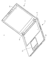
図1は、本開示の電子機器の一例であるパーソナルコンピュータ1の斜視図であり、図2は、図1のパーソナルコンピュータ1の本体ユニット2の一部の構成を示す概略図である。図1は、ラップトップ型のパーソナルコンピュータ1を開いた状態の外観を示す図である。図1、図2に示されるように、パーソナルコンピュータ1は、本体ユニット2と、表示ユニット3と、本体ユニット2と表示ユニット3との間に設けられたヒンジ部4とを備える。表示ユニット3は、ヒンジ部4を介して本体ユニット2と開閉可能に接続される。本体ユニット2は、例えばマグネシウムなどの金属製の金属筐体21と、当該金属筐体21上に設けられた樹脂製のキーボード22(図1では省略している)及びポインティングデバイス23とを備える。また、表示ユニット3には液晶表示パネル(LCD)31が設けられる。
[1. Constitution]
[1-1. overall structure]
FIG. 1 is a perspective view of a personal computer 1 which is an example of the electronic apparatus of the present disclosure, and FIG. 2 is a schematic diagram illustrating a configuration of a part of a main body unit 2 of the personal computer 1 of FIG. FIG. 1 is a diagram showing an appearance of a state in which a laptop personal computer 1 is opened. As shown in FIGS. 1 and 2, the personal computer 1 includes a main body unit 2, a display unit 3, and a hinge portion 4 provided between the main body unit 2 and the display unit 3. The display unit 3 is connected to the main unit 2 via the hinge portion 4 so as to be openable and closable. The main unit 2 includes a metal casing 21 made of metal such as magnesium, a resin keyboard 22 (not shown in FIG. 1) and a pointing device 23 provided on the metal casing 21. The display unit 3 is provided with a liquid crystal display panel (LCD) 31.

図2において破線で示すように、金属筐体21の内部のキーボードの裏側において、回路基板5が収容される。当該回路基板5には例えば無線LAN通信のためのアンテナモジュールが実装されている。また、例えばCPU(Central Processing Unit)、MPU(Micro Processing Unit)又はGPU(Graphics Processing Unit)などの演算処理装置(発熱体の一例)10が実装されている。   As shown by a broken line in FIG. 2, the circuit board 5 is accommodated on the back side of the keyboard inside the metal housing 21. For example, an antenna module for wireless LAN communication is mounted on the circuit board 5. An arithmetic processing device (an example of a heating element) 10 such as a CPU (Central Processing Unit), an MPU (Micro Processing Unit), or a GPU (Graphics Processing Unit) is mounted.

[1−1−1.開示の背景]
ここで、本開示に至った背景について説明する。CPU等の演算処理装置は例えば600MHz〜2.6GHzの高周波で動作して熱を発生させるとともにMHz、GHz単位の高周波ノイズを発生する。すなわち、演算処理装置10は、演算処理中に内部の回路抵抗によって発熱し、さらに演算処理速度に応じた高周波ノイズである電磁波を放出する。回路基板5に実装されたアンテナモジュールは、800MHz〜5GHzの周波数帯域を使用するので、演算処理装置10から発生する電磁波はアンテナモジュールを含む他の電子回路に影響を及ぼし、ひいてはパーソナルコンピュータ1の誤動作の要因となる。この問題を解決するため、本開示のパーソナルコンピュータ1は、演算処理装置10(すなわち、発熱体)に放熱ユニット6を接続し、さらに放熱ユニット6を接地させることにより、演算処理装置10により発生した電磁波を他の電子回路に放出させないように構成している。以下、放熱ユニット6の構成について説明する。
[1-1-1. Disclosure Background]
Here, the background that led to the present disclosure will be described. An arithmetic processing unit such as a CPU operates at a high frequency of, for example, 600 MHz to 2.6 GHz to generate heat and generate high frequency noise in units of MHz and GHz. That is, the arithmetic processing device 10 generates heat due to the internal circuit resistance during the arithmetic processing, and further emits electromagnetic waves that are high-frequency noise corresponding to the arithmetic processing speed. Since the antenna module mounted on the circuit board 5 uses a frequency band of 800 MHz to 5 GHz, electromagnetic waves generated from the arithmetic processing unit 10 affect other electronic circuits including the antenna module, and thus malfunction of the personal computer 1. It becomes a factor of. In order to solve this problem, the personal computer 1 of the present disclosure is generated by the arithmetic processing unit 10 by connecting the heat radiating unit 6 to the arithmetic processing unit 10 (that is, the heating element) and grounding the heat radiating unit 6. It is configured not to emit electromagnetic waves to other electronic circuits. Hereinafter, the configuration of the heat dissipation unit 6 will be described.

[1−2.放熱ユニットの構成]
[1−2−1.概要]
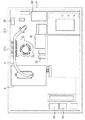
図3は、図2の本体ユニット2を底面側から見たときの平面図であり、図4は、図3の放熱ユニット6及びその近傍の構成を拡大して示した図である。ここで、図3は、図1のパーソナルコンピュータ1の底板を外した状態における本体ユニット2を底面側から見たときの平面図である。図3に示すように、金属筐体21内には、回路基板5、放熱ユニット6及び各種の電子部品30が配置されている。
[1-2. Configuration of heat dissipation unit]
[1-2-1. Overview]
FIG. 3 is a plan view of the main unit 2 shown in FIG. 2 when viewed from the bottom side, and FIG. 4 is an enlarged view of the configuration of the heat dissipation unit 6 shown in FIG. 3 and the vicinity thereof. Here, FIG. 3 is a plan view when the main unit 2 is viewed from the bottom side with the bottom plate of the personal computer 1 of FIG. 1 removed. As shown in FIG. 3, the circuit board 5, the heat radiating unit 6, and various electronic components 30 are arranged in the metal housing 21.

図4に示されるように、放熱ユニット6は、放熱体65と、送風ファンユニット66と、ヒートパイプ60と、受熱板61とを備える。   As shown in FIG. 4, the heat radiating unit 6 includes a heat radiating body 65, a blower fan unit 66, a heat pipe 60, and a heat receiving plate 61.

放熱体65は、金属筐体21の後壁21a近傍に設けられ、演算処理装置10からの熱が伝導される複数の放熱用フィン65aを有する。   The heat radiator 65 is provided in the vicinity of the rear wall 21a of the metal casing 21, and has a plurality of heat radiation fins 65a through which heat from the arithmetic processing device 10 is conducted.

送風ファンユニット66は、放熱体65に空気(冷却風)を送る。送風ファンユニット66は、送風ファンケース66aと、送風ファン66bと、吸入口66cと、排気口66dとを有する。送風ファンユニット66は、固定具70を用いて、金属筐体21に固定される。送風ファンケース66aの内部に収容された送風ファン66bが回転軸を軸心として回転し、送風ファンケース66aの上面に形成された吸入口66cから周囲の空気を取り込み、取り込まれた空気は、放熱体65と送風ファンユニット66との接続箇所に設けられた排気口66dにより放熱体65に送り込まれ、放熱体65を冷却する。   The blower fan unit 66 sends air (cooling air) to the radiator 65. The blower fan unit 66 includes a blower fan case 66a, a blower fan 66b, a suction port 66c, and an exhaust port 66d. The blower fan unit 66 is fixed to the metal casing 21 using a fixture 70. The blower fan 66b accommodated in the blower fan case 66a rotates about the rotation axis, takes ambient air from a suction port 66c formed on the upper surface of the blower fan case 66a, and the taken-in air dissipates heat. The heat radiating body 65 is sent to the heat radiating body 65 through an exhaust port 66 d provided at a connection portion between the body 65 and the blower fan unit 66, thereby cooling the heat radiating body 65.

受熱板61は、ヒートパイプ60の一端である受熱端60aに熱的に及び電気的に接続した状態で固着されている。受熱板61は金属板であり、演算処理装置10が発生する熱を受け取る。   The heat receiving plate 61 is fixed to a heat receiving end 60 a that is one end of the heat pipe 60 in a state of being thermally and electrically connected. The heat receiving plate 61 is a metal plate and receives heat generated by the arithmetic processing device 10.

ヒートパイプ60は、演算処理装置10で発生した熱を放熱体65に伝導する。ヒートパイプ60は、例えば棒状で銅製の金属伝導体である。具体的に、ヒートパイプ60は、銅製の筒状でその減圧された内部には少量の純水またはアルコール系液体が注入されている。注入された少量の純水またはアルコール系液体は、熱されると、蒸気となり、この蒸気により熱輸送が行われる。蒸気は、ヒートパイプ60の放熱部(ヒートパイプ60と放熱体65とが接触する部分、ヒートパイプ60の放熱端60c)で液化され、当該液化された純水またはアルコール系液体は、毛細管現象により受熱部(ヒートパイプ60の受熱端60a)へと戻る。ヒートパイプ60は、受熱板61の両端部に設けられた固定具62を用いて金属筐体21に固定される。演算処理装置10で生じた熱は、受熱板61を介してヒートパイプ60の受熱端60aに伝導され、さらに、受熱端60aから伝導部60bを介して、放熱端60cに伝導される。   The heat pipe 60 conducts heat generated in the arithmetic processing device 10 to the heat radiating body 65. The heat pipe 60 is, for example, a rod-shaped copper metal conductor. Specifically, the heat pipe 60 is a copper cylinder, and a small amount of pure water or an alcohol-based liquid is injected into the decompressed inside. A small amount of injected pure water or alcohol-based liquid becomes steam when heated, and heat is transported by this steam. The steam is liquefied at the heat radiating portion of the heat pipe 60 (the portion where the heat pipe 60 and the heat radiating body 65 are in contact with each other, the heat radiating end 60c of the heat pipe 60). It returns to the heat receiving part (heat receiving end 60a of the heat pipe 60). The heat pipe 60 is fixed to the metal casing 21 by using fixtures 62 provided at both ends of the heat receiving plate 61. The heat generated in the arithmetic processing unit 10 is conducted to the heat receiving end 60a of the heat pipe 60 through the heat receiving plate 61, and is further conducted from the heat receiving end 60a to the heat radiating end 60c through the conductive portion 60b.

[1−2−2.ヒートパイプの固定構造]
図4に示すように、ヒートパイプ60は、受熱端60aにおいて、固定具62により受熱板61を介して回路基板5に固定され、回路基板5が金属筐体21に固定される。さらに、ヒートパイプ60は、放熱端60cにおいて、固定具64により金属板69を介して金属筐体21に固定される。ヒートパイプ60の他の箇所は、金属筐体21に接触されずに浮いた状態にある。以下、ヒートパイプ60の固定構造について、より具体的に説明する。
[1-2-2. Fixing structure of heat pipe]
As shown in FIG. 4, the heat pipe 60 is fixed to the circuit board 5 via the heat receiving plate 61 by the fixture 62 at the heat receiving end 60 a, and the circuit board 5 is fixed to the metal casing 21. Furthermore, the heat pipe 60 is fixed to the metal casing 21 via the metal plate 69 by the fixture 64 at the heat radiating end 60c. Other portions of the heat pipe 60 are in a floating state without being in contact with the metal casing 21. Hereinafter, the fixing structure of the heat pipe 60 will be described more specifically.

図5Aは、図4のA−A’線に沿って切断したときの縦断面図である。図5Aにおいて、ヒートパイプ60の受熱端60aは、金属製の受熱板61に溶接あるいは導電性接着剤等により固着されている。これにより、当該受熱板61は、ヒートパイプ60に電気的及び熱的に接続される。受熱板61は、例えば金属製のネジなどの固定具62によって、熱源である演算処理装置10を熱伝導シート63を介して回路基板5及び金属筐体21に押し付けるように固定される。これにより、演算処理装置10と熱伝導シート63と受熱板61(ヒートパイプ60)とが密着し、演算処理装置10で発生した熱が、熱伝導シート63及び受熱板61を介して、ヒートパイプ60の受熱端60aに良好に伝達される。   FIG. 5A is a longitudinal sectional view taken along the line A-A ′ of FIG. 4. 5A, the heat receiving end 60a of the heat pipe 60 is fixed to a metal heat receiving plate 61 by welding or a conductive adhesive or the like. As a result, the heat receiving plate 61 is electrically and thermally connected to the heat pipe 60. The heat receiving plate 61 is fixed by a fixture 62 such as a metal screw so as to press the arithmetic processing unit 10 as a heat source against the circuit board 5 and the metal casing 21 via the heat conductive sheet 63. As a result, the arithmetic processing device 10, the heat conductive sheet 63 and the heat receiving plate 61 (heat pipe 60) are in close contact with each other, and the heat generated in the arithmetic processing device 10 is transferred to the heat pipe via the heat conductive sheet 63 and the heat receiving plate 61. 60 is transmitted to the heat receiving end 60a.

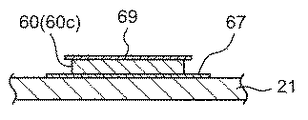
図5Bは、図4のB−B’線に沿って切断したときの縦断面図である。図5Bにおいて、ヒートパイプ60は、当該ヒートパイプ60の放熱端60cにおいて、熱伝導シート67を介して金属筐体21と熱的に接続される。このように、ヒートパイプ60の放熱端60cが金属筐体21に熱伝導シート67を介して熱的に接続することで、放熱端60cから金属筐体21に熱が良好に伝達される。   FIG. 5B is a longitudinal sectional view taken along the line B-B ′ of FIG. 4. In FIG. 5B, the heat pipe 60 is thermally connected to the metal casing 21 via the heat conductive sheet 67 at the heat radiating end 60 c of the heat pipe 60. As described above, the heat radiating end 60 c of the heat pipe 60 is thermally connected to the metal housing 21 via the heat conductive sheet 67, so that heat is favorably transmitted from the heat radiating end 60 c to the metal housing 21.

図5Cは、図4のC−C’線に沿って切断したときの縦断面図である。図5Cにおいて、ヒートパイプ60は、ヒートパイプ60の放熱端60cに熱的に及び電気的に接続した状態で固着された金属板69を用いて、金属筐体21に固定される。具体的には、ヒートパイプ60は、ヒートパイプ60の放熱端60cにおいて、例えば金属製のネジなどの固定具64によって、金属板69がヒートパイプ60を金属筐体21に押し付けるように、金属筐体21に固定される。これにより、ヒートパイプ60の放熱端60cが金属筐体21に密着し、放熱端60cから金属筐体21に熱が良好に伝達される。また、ヒートパイプ60と金属筐体21との間の接触抵抗を極力減少させることができる。そのため、ヒートパイプ60上を伝導する電磁波が金属筐体21に良好に伝達される。   FIG. 5C is a longitudinal sectional view taken along the line C-C ′ of FIG. 4. In FIG. 5C, the heat pipe 60 is fixed to the metal casing 21 using a metal plate 69 fixed in a state of being thermally and electrically connected to the heat radiating end 60 c of the heat pipe 60. Specifically, the heat pipe 60 includes a metal housing such that the metal plate 69 presses the heat pipe 60 against the metal housing 21 by a fixture 64 such as a metal screw at the heat radiating end 60 c of the heat pipe 60. It is fixed to the body 21. As a result, the heat radiating end 60 c of the heat pipe 60 is in close contact with the metal housing 21, and heat is transferred from the heat radiating end 60 c to the metal housing 21 in a favorable manner. Moreover, the contact resistance between the heat pipe 60 and the metal housing 21 can be reduced as much as possible. Therefore, the electromagnetic wave conducted on the heat pipe 60 is transmitted to the metal housing 21 satisfactorily.

[1−2−3.ヒートパイプ60の各部の配置]
ヒートパイプ60と放熱体65とが接触する位置(所定位置)と、放熱端60cとの間の距離は、放熱端60cの金属筐体21への接続位置における金属筐体21の温度が、所定位置における金属筐体21の温度よりも、所定温度以上低くなるような距離に設定する。ここで、所定温度は、放熱端60cにおける放熱を十分に行える温度である。図4に示すように、ヒートパイプ60と受熱板61とが接続する部分(ヒートパイプ60の受熱端60a)及びヒートパイプ60と金属筐体21とが接続する部分(ヒートパイプ60の放熱端60c)は、ヒートパイプ60と放熱体65とが接触する部分(ヒートパイプ60の伝導部60bの一部)よりも金属筐体21内においてより内側に位置される。この構成とすることにより、図2に示すように、ヒートパイプ60の放熱端60cにおいて、ヒートパイプ60が金属筐体21に熱的に接続される位置はキーボード22の領域内となる。ヒートパイプ60の放熱端60cと液晶表示パネル31との間に樹脂製のキーボード22が存在する。従って、パーソナルコンピュータ1を閉じた状態とした場合でも、ヒートパイプ60の放熱端60cと液晶表示パネル31との間に樹脂製のキーボード22が存在するので、ヒートパイプ60の放熱端60cから金属筐体21に放熱された熱は低い熱伝導率を有する樹脂製のキーボード22に伝達され、直接的に液晶表示パネル31に伝達されない。従って、演算処理装置10で生じた高熱による当該液晶パネル31の劣化が抑制される。また、ユーザーが触れる可能性のある後壁21aの領域から、受熱端60aおよび放熱端60cを離す構造となるため、ユーザーへの熱の影響を低減する効果も期待できる。
[1-2-3. Arrangement of each part of heat pipe 60]
The distance between the heat pipe 60 and the radiator 65 (predetermined position) and the heat radiating end 60c is such that the temperature of the metal casing 21 at the position where the heat radiating end 60c is connected to the metal casing 21 is predetermined. The distance is set to be lower than the temperature of the metal casing 21 at the position by a predetermined temperature or more. Here, the predetermined temperature is a temperature at which heat radiation at the heat radiation end 60c can be sufficiently performed. As shown in FIG. 4, a portion where the heat pipe 60 and the heat receiving plate 61 are connected (heat receiving end 60a of the heat pipe 60) and a portion where the heat pipe 60 and the metal housing 21 are connected (heat radiating end 60c of the heat pipe 60). ) Is positioned more inside in the metal casing 21 than a portion where the heat pipe 60 and the heat radiating body 65 are in contact (a part of the conductive portion 60b of the heat pipe 60). With this configuration, as shown in FIG. 2, the position where the heat pipe 60 is thermally connected to the metal housing 21 in the heat radiating end 60 c of the heat pipe 60 is within the region of the keyboard 22. A resin keyboard 22 exists between the heat radiating end 60 c of the heat pipe 60 and the liquid crystal display panel 31. Accordingly, even when the personal computer 1 is closed, the resin keyboard 22 exists between the heat radiating end 60 c of the heat pipe 60 and the liquid crystal display panel 31. The heat radiated to the body 21 is transmitted to the resin keyboard 22 having a low thermal conductivity, and is not directly transmitted to the liquid crystal display panel 31. Therefore, deterioration of the liquid crystal panel 31 due to high heat generated in the arithmetic processing device 10 is suppressed. Further, since the heat receiving end 60a and the heat radiating end 60c are separated from the region of the rear wall 21a that the user may touch, an effect of reducing the influence of heat on the user can be expected.

[2.作用]
以上のように構成されたパーソナルコンピュータ1について、放熱ユニット6による作用を以下に説明する。
[2. Action]
With respect to the personal computer 1 configured as described above, the operation of the heat dissipation unit 6 will be described below.

[2−1.電磁波の吸収作用]
演算処理装置10の動作時に発生した電磁波は、熱伝導シート63を介して受熱板61に伝播する。受熱板61に伝播された電磁波の一部は、金属製の固定具62を介して金属筐体21に伝播し(図5A参照)、残りの電磁波は、ヒートパイプ60の受熱端60a及び伝導部60bを介して、ヒートパイプ60の放熱端60cに伝播される。ヒートパイプ60の放熱端60cに伝播された電磁波は、金属製の固定具64を介して及び直接的に金属筐体21に伝播され(図5B参照)、かつ熱伝導シート67を介して金属筐体21に伝播される(図5C参照)。金属筐体21は接地(グランド電位に接続)されているのでこれにより、演算処理装置10から発生する電磁波の放射を防止できる。なお、ヒートパイプ60の放熱端60c、及び各固定具62、64と、金属筐体21との接触面積が大きいほど電磁波の放射を低減する能力(接地能力)は高くなる。
[2-1. Electromagnetic absorption effect]
Electromagnetic waves generated during the operation of the arithmetic processing apparatus 10 propagate to the heat receiving plate 61 through the heat conductive sheet 63. A part of the electromagnetic wave propagated to the heat receiving plate 61 is propagated to the metal casing 21 through the metal fixture 62 (see FIG. 5A), and the remaining electromagnetic waves are transmitted to the heat receiving end 60a and the conductive portion of the heat pipe 60. It propagates to the heat radiating end 60c of the heat pipe 60 via 60b. The electromagnetic waves propagated to the heat radiating end 60c of the heat pipe 60 are propagated through the metal fixture 64 and directly to the metal casing 21 (see FIG. 5B), and through the heat conductive sheet 67, the metal casing. Propagated to the body 21 (see FIG. 5C). Since the metal casing 21 is grounded (connected to the ground potential), it is possible to prevent radiation of electromagnetic waves generated from the arithmetic processing unit 10. In addition, the capability (grounding capability) to reduce the radiation of electromagnetic waves increases as the contact area between the heat radiating end 60c of the heat pipe 60 and the fixtures 62 and 64 and the metal casing 21 increases.

[2−2.放熱作用]
演算処理装置10の動作時に発生した熱は、熱伝導シート63及び受熱板61を介してヒートパイプ60の受熱端60aに伝導される。受熱端60aにおいて受け取られた熱は、ヒートパイプ60の伝導部60bを伝導する。ヒートパイプ60の伝導部60bを伝導する熱は、放熱用フィン65に伝導され、放熱用フィン65に伝導された熱は、その表面から放出される。放出された熱は、送風ファンユニット66からの風により金属筐体21の開口部21bを介して外部に放出される。残りの熱は、ヒートパイプ60の伝導部60bを伝導し、当該ヒートパイプ60の放熱端60cから直接的にあるいは熱伝導シート67を介して、金属筐体21に伝導される。金属筐体21に伝導された熱は、金属筐体21自身が熱の拡散によって温度を下げることを目的とした部品(ヒートシンク)として機能することにより、外部空間に放熱される。
[2-2. Heat dissipation]
Heat generated during operation of the arithmetic processing device 10 is conducted to the heat receiving end 60 a of the heat pipe 60 through the heat conductive sheet 63 and the heat receiving plate 61. The heat received at the heat receiving end 60 a is conducted through the conductive portion 60 b of the heat pipe 60. The heat conducted through the conductive portion 60b of the heat pipe 60 is conducted to the heat radiation fin 65, and the heat conducted to the heat radiation fin 65 is released from the surface. The released heat is released to the outside through the opening 21 b of the metal housing 21 by the wind from the blower fan unit 66. The remaining heat is conducted through the conductive portion 60 b of the heat pipe 60, and is conducted to the metal housing 21 directly from the heat radiating end 60 c of the heat pipe 60 or via the heat conductive sheet 67. The heat conducted to the metal casing 21 is radiated to the external space by the metal casing 21 itself functioning as a component (heat sink) intended to lower the temperature by diffusion of heat.

ここで、放熱体65から放出される熱により当該放熱体65付近の金属筐体21はすでに高温となっている。仮に、ヒートパイプ60を伝導する熱を放熱体65とヒートパイプ60とが接触する位置付近で金属筐体21に放出させた場合、放熱体65付近の金属筐体21の温度がさらに上昇する。これに対処するため、本実施形態では、ヒートパイプ60を放熱体65からさらに延在させ、金属筐体21内のさらに内側において金属筐体21に接続させる。この構成とすることにより、金属筐体21において比較的温度が低い箇所に熱が放出される。   Here, the metal casing 21 in the vicinity of the radiator 65 is already at a high temperature due to the heat released from the radiator 65. If the heat conducted through the heat pipe 60 is released to the metal casing 21 near the position where the heat radiating body 65 and the heat pipe 60 are in contact with each other, the temperature of the metal casing 21 near the heat radiating body 65 further increases. In order to cope with this, in the present embodiment, the heat pipe 60 is further extended from the heat radiating body 65 and connected to the metal casing 21 further inside the metal casing 21. With this configuration, heat is released to the metal housing 21 where the temperature is relatively low.

[3.効果等]
以上のように、本実施の形態に係るパーソナルコンピュータ1は、発熱体である演算処理装置10と、放熱体65と、導電性を有し、かつ演算処理装置10で発生した熱を放熱体65に伝導するヒートパイプ60と、演算処理装置10、放熱体65、及びヒートパイプ60を収容する金属筐体21と、を備え、ヒートパイプ60は、一端において演算処理装置10に熱的に及び電気的に接続した状態で固着され、受熱端60aと放熱端60cとの間の所定位置において放熱体65に熱的に及び電気的に接続した状態で固着され、放熱端60cにおいて金属筐体21に熱的に及び電気的に接続した状態で固着される。
[3. Effect]
As described above, the personal computer 1 according to the present embodiment has the arithmetic processing device 10 that is a heat generator, the heat radiating body 65, and the heat generated in the arithmetic processing device 10 that has conductivity and the heat radiating body 65. A heat pipe 60 that conducts heat to the arithmetic processing unit 10, a heat radiating body 65, and a metal casing 21 that houses the heat pipe 60. The heat pipe 60 is thermally and electrically connected to the arithmetic processing unit 10 at one end. Fixed in a connected state, fixed in a thermally and electrically connected state to the radiator 65 at a predetermined position between the heat receiving end 60a and the heat radiating end 60c, and attached to the metal casing 21 at the heat radiating end 60c. It is fixed in a thermally and electrically connected state.

この構成により、当該演算処理装置10で生じた電磁波はヒートパイプ60により伝播して当該ヒートパイプ60の受熱端60a及び放熱端60cを介して金属筐体21に吸収させることができる。従って、演算処理装置10により発生した電磁波が演算処理装置10以外の電子回路に放出されるのが抑制される。そのため、電磁波に基づくパーソナルコンピュータ1の誤動作を防止することが可能となる。さらに、演算処理装置10の動作時に発生した熱はヒートパイプ60を介して放熱体65及び金属筐体21に伝導し、外部空間に放熱される。   With this configuration, the electromagnetic wave generated in the arithmetic processing device 10 can be propagated through the heat pipe 60 and absorbed by the metal casing 21 via the heat receiving end 60a and the heat radiating end 60c of the heat pipe 60. Therefore, electromagnetic waves generated by the arithmetic processing device 10 are suppressed from being emitted to electronic circuits other than the arithmetic processing device 10. For this reason, it is possible to prevent malfunction of the personal computer 1 based on electromagnetic waves. Further, the heat generated during the operation of the arithmetic processing device 10 is conducted to the heat radiating body 65 and the metal casing 21 through the heat pipe 60 and is radiated to the external space.

また、本実施の形態に係るパーソナルコンピュータ1において、所定位置と他端との間の距離は、他端の金属筐体21への接続位置における金属筐体21の温度が、所定位置における金属筐体21の温度よりも、所定温度以上低くなる距離である。   In the personal computer 1 according to the present embodiment, the distance between the predetermined position and the other end is such that the temperature of the metal casing 21 at the connection position to the metal casing 21 at the other end is the same as the metal casing at the predetermined position. The distance is lower than the temperature of the body 21 by a predetermined temperature or more.

この構成により、ヒートパイプ60と放熱体65とが接触する所定位置での金属筐体21の温度よりも、放熱端60cでの金属筐体21の温度が低くなる。従って、演算処理装置10で発生した熱をより温度の低い位置において金属筐体21に放熱することができる。従って、放熱性能がより向上する。   With this configuration, the temperature of the metal casing 21 at the heat radiating end 60c is lower than the temperature of the metal casing 21 at a predetermined position where the heat pipe 60 and the heat radiator 65 are in contact with each other. Therefore, the heat generated in the arithmetic processing device 10 can be radiated to the metal casing 21 at a lower temperature position. Therefore, the heat dissipation performance is further improved.

また、本実施の形態に係るパーソナルコンピュータ1において、ヒートパイプ60の受熱端60a及び放熱端60cは、所定位置よりも金属筐体21内において内側に位置している。   Further, in the personal computer 1 according to the present embodiment, the heat receiving end 60a and the heat radiating end 60c of the heat pipe 60 are located inside the metal casing 21 with respect to a predetermined position.

この構成により、所定位置と受熱端60a及び放熱端60cとの間の距離をそれぞれ大きくしやすくなる。従って、発熱する各箇所を分散させることができる。従って、放熱性能が向上する。   With this configuration, the distance between the predetermined position and the heat receiving end 60a and the heat radiating end 60c can be easily increased. Accordingly, the portions that generate heat can be dispersed. Therefore, the heat dissipation performance is improved.

また、本実施の形態に係るパーソナルコンピュータ1において、ヒートパイプ60の放熱端60cに熱的に及び電気的に接続した状態で固着された金属板69と、金属板69を金属筐体21に固定する第1の固定具64とをさらに備え、ヒートパイプ60は、金属板69及び第1の固定具64を介して、金属筐体21に熱的に及び電気的に接続される。 Further, in the personal computer 1 according to the present embodiment, the metal plate 69 fixed in a state of being thermally and electrically connected to the heat radiating end 60 c of the heat pipe 60 and the metal plate 69 are fixed to the metal casing 21. further comprising a first fastener 64, the heat pipe 60 via the metal plate 69 and the first fixture 64 is thermally and electrically connected to the metal casing 21.

この構成により、ヒートパイプ60を伝播した電磁波は、放熱端60cにおいて金属板69及び第1の固定具64を介して金属筐体21に吸収される。従って、電磁波に基づくパーソナルコンピュータ1の誤動作をより防止することが可能となる。また、ヒートパイプ60を伝導した熱は、放熱端60cにおいて、金属板69及び第1の固定具64を介して金属筐体21に放熱させることが可能となる。 With this configuration, the electromagnetic wave propagated through the heat pipe 60 is absorbed by the metal casing 21 through the metal plate 69 and the first fixture 64 at the heat radiating end 60c. Accordingly, it is possible to further prevent malfunction of the personal computer 1 based on electromagnetic waves. Further, the heat conducted through the heat pipe 60 can be radiated to the metal casing 21 through the metal plate 69 and the first fixture 64 at the heat radiating end 60c.

また、本実施の形態に係るパーソナルコンピュータ1において、ヒートパイプ60と演算処理装置10との間に熱伝導ゴム90などの熱伝導部材を備えた。   Further, in the personal computer 1 according to the present embodiment, a heat conducting member such as the heat conducting rubber 90 is provided between the heat pipe 60 and the arithmetic processing unit 10.

この構成により、ヒートパイプ60と演算処理装置10とが熱伝導ゴム90を介して密着する。そのため、熱伝導ゴム90を配置しない場合と比較すると、演算処理装置10で発生した熱をより確実にヒートパイプ60の受熱端60aに伝導させることが可能となる。従って、放熱性能がより向上する。   With this configuration, the heat pipe 60 and the arithmetic processing unit 10 are in close contact with each other via the heat conductive rubber 90. Therefore, it is possible to more reliably conduct the heat generated in the arithmetic processing device 10 to the heat receiving end 60a of the heat pipe 60 as compared with the case where the heat conductive rubber 90 is not disposed. Therefore, the heat dissipation performance is further improved.

また、本実施の形態に係るパーソナルコンピュータ1において、ヒートパイプ60の受熱端60aに熱的に及び電気的に接続した状態で固着された受熱板61と、受熱板61を金属筐体21に固定する第2の固定具62を備え、ヒートパイプ60は、受熱板61及び第2の固定具62を介して、金属筐体21に熱的に及び電気的に接続される。   Further, in the personal computer 1 according to the present embodiment, the heat receiving plate 61 fixed in a state of being thermally and electrically connected to the heat receiving end 60 a of the heat pipe 60 and the heat receiving plate 61 are fixed to the metal casing 21. The heat pipe 60 is thermally and electrically connected to the metal housing 21 via the heat receiving plate 61 and the second fixture 62.

この構成により、演算処理装置10で生じた電磁波は、受熱端60aにおいて受熱板61及び第2の固定具62を介してヒートパイプ60の受熱端60aに伝播し、伝導部60b及び放熱端60cを介して金属筐体21に吸収させることが可能となる。従って、電磁波によるパーソナルコンピュータ1の誤動作をより確実に抑制することが可能となる。また、演算処理装置10で生じた熱は、受熱板61及び第2の固定具62を介して受熱端60aに伝導させることが可能となる。従って、放熱性能が向上する。 With this configuration, the electromagnetic wave generated in the arithmetic processing unit 10 propagates to the heat receiving end 60a of the heat pipe 60 via the heat receiving plate 61 and the second fixture 62 at the heat receiving end 60a, and passes through the conductive portion 60b and the heat radiating end 60c. It becomes possible to make it absorb in the metal housing | casing 21. Therefore, it is possible to more reliably suppress malfunction of the personal computer 1 due to electromagnetic waves. In addition, the heat generated in the arithmetic processing device 10 can be conducted to the heat receiving end 60a through the heat receiving plate 61 and the second fixture 62. Therefore, the heat dissipation performance is improved.

また、本実施の形態に係るパーソナルコンピュータ1において、ヒートパイプ60は、金属により形成される。   Moreover, in the personal computer 1 according to the present embodiment, the heat pipe 60 is made of metal.

この構成により、ヒートパイプ60に熱及び電磁波を伝導(伝播)することが可能となる。従って、演算処理装置10で生じた電磁波は、受熱端60aにおいて受熱板61及び第2の固定具62を介してヒートパイプ60の受熱端60aに伝播し、伝導部60b及び放熱端60cを介して金属筐体21に吸収させることが可能となる。従って、電磁波によるパーソナルコンピュータ1の誤動作をより確実に抑制することが可能となる。また、演算処理装置10で生じた熱は、受熱板61及び第2の固定具62を介して受熱端60aに伝導させることが可能となる。従って、放熱性能が向上する。 With this configuration, heat and electromagnetic waves can be conducted (propagated) to the heat pipe 60. Therefore, the electromagnetic wave generated in the arithmetic processing unit 10 propagates to the heat receiving end 60a of the heat pipe 60 via the heat receiving plate 61 and the second fixture 62 at the heat receiving end 60a, and passes through the conductive portion 60b and the heat radiating end 60c. It can be absorbed by the metal casing 21. Therefore, it is possible to more reliably suppress malfunction of the personal computer 1 due to electromagnetic waves. In addition, the heat generated in the arithmetic processing device 10 can be conducted to the heat receiving end 60a through the heat receiving plate 61 and the second fixture 62. Therefore, the heat dissipation performance is improved.

(他の実施の形態)
以上のように、本出願において開示する技術の例示として、実施の形態1を説明した。しかしながら、本開示における技術は、これに限定されず、適宜、変更、置き換え、付加、省略などを行った実施の形態にも適用可能である。また、上記実施の形態1で説明した各構成要素を組み合わせて、新たな実施の形態とすることも可能である。
(Other embodiments)
As described above, the first embodiment has been described as an example of the technique disclosed in the present application. However, the technology in the present disclosure is not limited to this, and can also be applied to an embodiment in which changes, replacements, additions, omissions, and the like are appropriately performed. Moreover, it is also possible to combine each component demonstrated in the said Embodiment 1, and it can also be set as a new embodiment.

例えば、上述した実施の形態1では、図5Aに図示するように、演算処理装置10を熱伝導シート63を介して受熱板61に電気的に及び熱的に接続したが、本開示はこれに限定されない。例えば、図6に図示するように、さらに受熱板61の下に例えば熱伝導ゴム90などの熱伝導部材を設けてもよい。なお、この熱伝導ゴム90に代えて、金属板を設けてもよい。また、受熱板61と回路基板5との間の部分に固定具62のスプリング等の部材を挿入してもよい。このように構成することでスプリングの付勢力により、押し付け時の力を均一に分散させることができる。また、上述した実施の形態では、電子機器の一例が、パーソナルコンピュータ1である例を説明したが、本開示はこれに限定されない。例えばタブレット端末、携帯電話、ムービー、携帯TV、ポータブルBDプレーヤーなどの電子機器に広く適用することが可能である。   For example, in Embodiment 1 described above, the arithmetic processing unit 10 is electrically and thermally connected to the heat receiving plate 61 via the heat conductive sheet 63 as illustrated in FIG. 5A. It is not limited. For example, as illustrated in FIG. 6, a heat conductive member such as a heat conductive rubber 90 may be further provided below the heat receiving plate 61. Note that a metal plate may be provided in place of the heat conductive rubber 90. Further, a member such as a spring of the fixture 62 may be inserted between the heat receiving plate 61 and the circuit board 5. With this configuration, the pressing force can be uniformly dispersed by the biasing force of the spring. In the above-described embodiment, an example in which the electronic apparatus is the personal computer 1 has been described, but the present disclosure is not limited thereto. For example, the present invention can be widely applied to electronic devices such as tablet terminals, mobile phones, movies, mobile TVs, and portable BD players.

また、上述した実施の形態1では、ヒートパイプ60の放熱端60cにおいて、ヒートパイプ60を金属筐体21に固定したが、本開示はこれに限定されない。例えば、ヒートパイプ60の放熱端60cにおいて、ヒートパイプ60を別の電子回路が実装された回路基板(図示せず)の接地電極に固定してもよい。この場合には、回路基板5の接地電位と回路基板(図示せず)の接地電位とを同電位にする必要がある。この構成とすることにより、上述した実施の形態1と同様の効果を得ることができる。   Moreover, in Embodiment 1 mentioned above, although the heat pipe 60 was fixed to the metal housing | casing 21 in the thermal radiation end 60c of the heat pipe 60, this indication is not limited to this. For example, at the heat radiating end 60c of the heat pipe 60, the heat pipe 60 may be fixed to a ground electrode of a circuit board (not shown) on which another electronic circuit is mounted. In this case, the ground potential of the circuit board 5 and the ground potential of the circuit board (not shown) need to be the same potential. By adopting this configuration, it is possible to obtain the same effects as those of the first embodiment described above.

また、上述した実施の形態1では、ヒートパイプ60の受熱端60a及びヒートパイプ60の放熱端60cは、ヒートパイプ60と放熱体65とが接触する部分よりも金属筐体21内においてより内側に位置したが、本開示はこれに限定されない。例えば、ヒートパイプ60は、当該ヒートパイプ60と放熱体65とが接触する位置からパーソナルコンピュータ1の後壁21aに沿って真っ直ぐに延在させてもよい。この構成によっても、当該演算処理装置10で生じた電磁波はヒートパイプ60により伝播して当該ヒートパイプ60の受熱端60a及び放熱端60cを介して金属筐体21に吸収させることができる。さらに、演算処理装置10の動作時に発生した熱はヒートパイプ60を介して放熱体65及び金属筐体21に伝導し、外部空間に放熱される。   Moreover, in Embodiment 1 mentioned above, the heat receiving end 60a of the heat pipe 60 and the heat radiating end 60c of the heat pipe 60 are more inside in the metal housing 21 than the part where the heat pipe 60 and the heat radiating body 65 are in contact. Although positioned, the present disclosure is not so limited. For example, the heat pipe 60 may extend straight along the rear wall 21a of the personal computer 1 from a position where the heat pipe 60 and the heat radiating body 65 are in contact with each other. Also with this configuration, the electromagnetic wave generated in the arithmetic processing device 10 can be propagated through the heat pipe 60 and absorbed by the metal casing 21 via the heat receiving end 60a and the heat radiating end 60c of the heat pipe 60. Further, the heat generated during the operation of the arithmetic processing device 10 is conducted to the heat radiating body 65 and the metal casing 21 through the heat pipe 60 and is radiated to the external space.

さらに、上述した実施の形態1では、金属製のヒートパイプ60を用いたが、本開示はこれに限定されない。例えば、ヒートパイプ60は、カーボン製などの、熱及び電気(電磁波)を伝えることができる部材を用いて形成されてもよい。この構成とすることにより、上述した実施の形態1と同様の効果を得ることができる。   Furthermore, in Embodiment 1 mentioned above, although the metal heat pipe 60 was used, this indication is not limited to this. For example, the heat pipe 60 may be formed using a member that can transmit heat and electricity (electromagnetic waves), such as carbon. By adopting this configuration, it is possible to obtain the same effects as those of the first embodiment described above.

以上のように、本開示における技術の例示として、実施の形態を説明した。そのために、添付図面および詳細な説明を提供した。   As described above, the embodiments have been described as examples of the technology in the present disclosure. For this purpose, the accompanying drawings and detailed description are provided.

したがって、添付図面および詳細な説明に記載された構成要素の中には、課題解決のために必須な構成要素だけでなく、上記技術を例示するために、課題解決のためには必須でない構成要素も含まれ得る。そのため、それらの必須ではない構成要素が添付図面や詳細な説明に記載されていることをもって、直ちに、それらの必須ではない構成要素が必須であるとの認定をするべきではない。   Accordingly, among the components described in the accompanying drawings and the detailed description, not only the components essential for solving the problem, but also the components not essential for solving the problem in order to illustrate the above technique. May also be included. Therefore, it should not be immediately recognized that these non-essential components are essential as those non-essential components are described in the accompanying drawings and detailed description.

また、上述の実施の形態は、本開示における技術を例示するためのものであるから、特許請求の範囲またはその均等の範囲において種々の変更、置き換え、付加、省略などを行うことができる。   Moreover, since the above-mentioned embodiment is for demonstrating the technique in this indication, a various change, replacement, addition, abbreviation, etc. can be performed in a claim or its equivalent range.

本開示は、電磁波及び熱を発生する電子機器であれば適用可能である。具体的には、タブレット端末、携帯電話、ムービー、携帯TV、ポータブルBDプレーヤーなどに、本開示は適用可能である。   The present disclosure can be applied to any electronic device that generates electromagnetic waves and heat. Specifically, the present disclosure is applicable to tablet terminals, mobile phones, movies, mobile TVs, portable BD players, and the like.

1…パーソナルコンピュータ、
2…本体ユニット、
3…表示ユニット、
4…ヒンジ部、
5…回路基板、
6…放熱ユニット、
10…発熱体、
21…金属筐体、
21a…後壁、
21b…開口部、
22…キーボード、
23…ポインティングデバイス、
31…液晶表示パネル(LCD)、
60…ヒートパイプ、
60a…受熱端、
60b…伝導部、
60c…放熱端、
61…受熱板、
62,64,67,70…固定具、
63,67…熱伝導シート、
65…放熱体、
65a…放熱用フィン、
66…送風ファンユニット、
66a…送風ファンケース、
66b…送風ファン、
66c…吸入口、
66d…排気口、
69…金属板、
90…熱伝導ゴム。
1 ... Personal computer,
2 ... Main unit,
3. Display unit,
4 ... Hinge part,
5 ... Circuit board,
6 ... Heat dissipation unit,
10 ... heating element,
21 ... Metal casing,
21a ... rear wall,
21b ... opening,
22 ... Keyboard,
23 ... pointing device,
31 ... Liquid crystal display panel (LCD),
60 ... heat pipe,
60a ... heat receiving end,
60b ... conduction part,
60c ... radiation end,
61 ... heat receiving plate,
62, 64, 67, 70 ... a fixture,
63, 67 ... heat conduction sheet,
65 ... radiator,
65a ... fin for heat radiation,
66 ... Blower fan unit,
66a ... Blower fan case,
66b ... Blower fan,
66c ... suction port,
66d ... exhaust port,
69 ... metal plate,
90: Thermally conductive rubber.

Claims (7)

発熱体と、
放熱体と、
導電性を有し、かつ上記発熱体で発生した熱を上記放熱体に伝導する伝導体と、
上記発熱体、上記放熱体、及び上記伝導体を収容する体と、を備え、
上記伝導体は、一端において上記発熱体に熱的に続した状態で接し、上記一端と他端との間の所定位置において上記放熱体に熱的に続した状態で接し、上記所定位置から延在した位置にある他端において上記体に熱的に続した状態で接し
上記伝導体の上記一端及び上記他端は、上記所定位置に最も近い上記筐体の側壁に対して、上記所定位置よりも上記筐体の内側に位置していることを特徴とする、
電子機器。
A heating element;
A radiator,
A conductor having conductivity and conducting heat generated in the heating element to the radiator;
A housing for housing the heating element, the heat radiator, and the conductor;
The conductor is in contact while thermally connected to the heating body at one end in contact while thermally connected to the heat radiator in a predetermined position between the one end and the other end, the predetermined position thermally contacting contact with connection state in the housing at the other end at a location extending from,
The one end and the other end of the conductor are located on the inner side of the casing relative to the predetermined position with respect to the side wall of the casing closest to the predetermined position.
Electronics.
上記所定位置と上記他端との間の距離は、上記他端の上記体への接続位置における上記体の温度が、上記所定位置における上記体の温度よりも、所定温度以上低くなる距離である、請求項1記載の電子機器。 The distance between the predetermined position and the other end, the temperature of the housing at the connection position to the housing of said other end, than the temperature of the housing in the predetermined position is lower than a predetermined temperature The electronic device according to claim 1, wherein the electronic device is a distance. 上記伝導体の上記他端に熱的に続した状態で接した金属板と、上記金属板を上記体に固定する第1の固定具とをさらに備え、
上記伝導体は、上記金属板及び上記第1の固定具を介して、上記体に熱的に続されることを特徴とする請求項1または2に記載の電子機器。
Further comprising a metal plate in contact in a state of thermally connected to the other end of the conductor, and a first fastener for securing the metal plate to the housing,
The conductor is via the metal plate and the first fastener, the electronic device according to claim 1 or 2, characterized in that it is thermally connected to the housing.
上記伝導体と上記発熱体との間に熱伝導部材を備えたことを特徴とする請求項1〜のうちのいずれか1つに記載の電子機器。 Electronic device according to any one of claims 1-3, characterized in that it comprises a heat conducting member between the conductor and the heating element. 上記伝導体の上記一端に熱的に続した状態で接した受熱板と、上記受熱板を上記体に固定する第2の固定具を備え、
上記伝導体は、上記受熱板及び上記第2の固定具を介して、上記体に熱的に続されることを特徴とする請求項1〜のうちのいずれか1つに記載の電子機器。
Comprising a heat-receiving plate in contact in a state of thermally connected to the one end of the conductor, a second fastener for securing said heat-receiving plate in the housing,
The conductor, through the heat-receiving plate and the second fixture according to any one of claims 1-4, characterized in that it is thermally connected to the housing Electronics.
上記伝導体は、金属により形成されることを特徴とする請求項1〜のうちのいずれか1つに記載の電子機器。 The electronic device according to the conductor, any one of claims 1-5, characterized in that it is formed of a metal. 上記伝導体は、ヒートパイプであることを特徴とする請求項1〜のうちのいずれか1つに記載の電子機器。 The electronic device according to any one of claims 1 to 6 , wherein the conductor is a heat pipe.
JP2014192910A 2014-09-22 2014-09-22 Electronics Active JP6473920B2 (en)

Priority Applications (1)

Application Number Priority Date Filing Date Title
JP2014192910A JP6473920B2 (en) 2014-09-22 2014-09-22 Electronics

Applications Claiming Priority (1)

Application Number Priority Date Filing Date Title
JP2014192910A JP6473920B2 (en) 2014-09-22 2014-09-22 Electronics

Publications (3)

Publication Number Publication Date
JP2016066119A JP2016066119A (en) 2016-04-28
JP2016066119A5 JP2016066119A5 (en) 2017-06-15
JP6473920B2 true JP6473920B2 (en) 2019-02-27

Family

ID=55805464

Family Applications (1)

Application Number Title Priority Date Filing Date
JP2014192910A Active JP6473920B2 (en) 2014-09-22 2014-09-22 Electronics

Country Status (1)

Country Link
JP (1) JP6473920B2 (en)

Families Citing this family (3)

* Cited by examiner, † Cited by third party
Publication number Priority date Publication date Assignee Title
JP2022094020A (en) * 2020-12-14 2022-06-24 レノボ・シンガポール・プライベート・リミテッド Electronic device and cooling module
JP7240470B1 (en) 2021-10-18 2023-03-15 レノボ・シンガポール・プライベート・リミテッド Electronics and cooling modules
WO2023199607A1 (en) * 2022-04-11 2023-10-19 株式会社ソニー・インタラクティブエンタテインメント Electronic device

Family Cites Families (4)

* Cited by examiner, † Cited by third party
Publication number Priority date Publication date Assignee Title
US5712762A (en) * 1996-03-01 1998-01-27 Compaq Computer Corporation Computer having a heat sink structure incorporated therein
US6535386B2 (en) * 2000-12-05 2003-03-18 Intel Corporation Electronic assembly having a heat pipe that conducts heat from a semiconductor die
US7057895B2 (en) * 2003-06-30 2006-06-06 Intel Corporation Thermal standoff for close proximity thermal management
JP4869419B2 (en) * 2010-03-18 2012-02-08 株式会社東芝 Electronics

Also Published As

Publication number Publication date
JP2016066119A (en) 2016-04-28

Similar Documents

Publication Publication Date Title
JP7170182B2 (en) Electronics
JP3602771B2 (en) Portable electronic devices
US8228239B2 (en) Heat-dissipating wireless communication system
US9357676B2 (en) Cooling device and electronic apparatus
US10114444B2 (en) Electronic device having an active edge
JP2011081437A (en) Electronic equipment
WO2015074447A1 (en) Mobile terminal heat dissipation apparatus and shielding cover frame
JP6473920B2 (en) Electronics
JP2009094196A (en) Heat dissipation structure of portable communication apparatus
JP4651411B2 (en) ANTENNA DEVICE AND RADIO DEVICE
JP2007049015A (en) Electronic device structure and electronic device using the same
JP6649854B2 (en) Electronics
CN114489243A (en) Information equipment
JP6311222B2 (en) Electronic device and heat dissipation method
JP2016066119A5 (en)
JPH09293985A (en) Electronic apparatus
CN212181406U (en) Electronic device
JP6582718B2 (en) Electronic electrical equipment
JP2006245025A (en) Heat dissipation structure of electronic apparatus
JP2007005390A (en) Electronic device and electronic component
JPH11110084A (en) Information processor
JPH05243434A (en) Electronic component cooling device
TW201244617A (en) Computer device
TW201328577A (en) Heat sink device and an electronic apparatus using the same
JP2002123336A (en) Information processor

Legal Events

Date Code Title Description
A521 Written amendment

Free format text: JAPANESE INTERMEDIATE CODE: A523

Effective date: 20170508

A621 Written request for application examination

Free format text: JAPANESE INTERMEDIATE CODE: A621

Effective date: 20170508

A131 Notification of reasons for refusal

Free format text: JAPANESE INTERMEDIATE CODE: A131

Effective date: 20180417

A521 Written amendment

Free format text: JAPANESE INTERMEDIATE CODE: A523

Effective date: 20180618

A131 Notification of reasons for refusal

Free format text: JAPANESE INTERMEDIATE CODE: A131

Effective date: 20181023

A521 Written amendment

Free format text: JAPANESE INTERMEDIATE CODE: A523

Effective date: 20181219

TRDD Decision of grant or rejection written
A01 Written decision to grant a patent or to grant a registration (utility model)

Free format text: JAPANESE INTERMEDIATE CODE: A01

Effective date: 20190108

A61 First payment of annual fees (during grant procedure)

Free format text: JAPANESE INTERMEDIATE CODE: A61

Effective date: 20190115

R151 Written notification of patent or utility model registration

Ref document number: 6473920

Country of ref document: JP

Free format text: JAPANESE INTERMEDIATE CODE: R151