JP6473806B2 - Method and apparatus for separating display modules joined by a liquid optically transparent adhesive - Google Patents
Method and apparatus for separating display modules joined by a liquid optically transparent adhesive Download PDFInfo
- Publication number
- JP6473806B2 JP6473806B2 JP2017514750A JP2017514750A JP6473806B2 JP 6473806 B2 JP6473806 B2 JP 6473806B2 JP 2017514750 A JP2017514750 A JP 2017514750A JP 2017514750 A JP2017514750 A JP 2017514750A JP 6473806 B2 JP6473806 B2 JP 6473806B2
- Authority
- JP
- Japan
- Prior art keywords
- light emitting
- emitting diode
- adhesive
- plane
- emitting diodes
- Prior art date
- Legal status (The legal status is an assumption and is not a legal conclusion. Google has not performed a legal analysis and makes no representation as to the accuracy of the status listed.)
- Active
Links
- 239000000853 adhesive Substances 0.000 title claims description 53
- 230000001070 adhesive effect Effects 0.000 title claims description 53
- 238000000034 method Methods 0.000 title claims description 40
- 239000007788 liquid Substances 0.000 title claims description 15
- 230000005670 electromagnetic radiation Effects 0.000 claims description 59
- 238000001816 cooling Methods 0.000 claims description 8
- 238000010438 heat treatment Methods 0.000 claims description 7
- 229910052782 aluminium Inorganic materials 0.000 claims description 3
- XAGFODPZIPBFFR-UHFFFAOYSA-N aluminium Chemical compound [Al] XAGFODPZIPBFFR-UHFFFAOYSA-N 0.000 claims description 3
- 239000004973 liquid crystal related substance Substances 0.000 claims description 2
- 229910052751 metal Inorganic materials 0.000 claims description 2
- 239000002184 metal Substances 0.000 claims description 2
- 230000003287 optical effect Effects 0.000 description 18
- 239000006059 cover glass Substances 0.000 description 10
- 238000000926 separation method Methods 0.000 description 7
- 239000011521 glass Substances 0.000 description 4
- 239000010410 layer Substances 0.000 description 4
- 229910052724 xenon Inorganic materials 0.000 description 4
- FHNFHKCVQCLJFQ-UHFFFAOYSA-N xenon atom Chemical compound [Xe] FHNFHKCVQCLJFQ-UHFFFAOYSA-N 0.000 description 4
- 230000005540 biological transmission Effects 0.000 description 3
- KFZMGEQAYNKOFK-UHFFFAOYSA-N Isopropanol Chemical compound CC(C)O KFZMGEQAYNKOFK-UHFFFAOYSA-N 0.000 description 2
- 238000010521 absorption reaction Methods 0.000 description 2
- 239000012790 adhesive layer Substances 0.000 description 2
- 238000007796 conventional method Methods 0.000 description 2
- QSHDDOUJBYECFT-UHFFFAOYSA-N mercury Chemical compound [Hg] QSHDDOUJBYECFT-UHFFFAOYSA-N 0.000 description 2
- 229910052753 mercury Inorganic materials 0.000 description 2
- 229910001507 metal halide Inorganic materials 0.000 description 2
- 150000005309 metal halides Chemical class 0.000 description 2
- 229920003023 plastic Polymers 0.000 description 2
- 239000002313 adhesive film Substances 0.000 description 1
- 238000005452 bending Methods 0.000 description 1
- 238000003776 cleavage reaction Methods 0.000 description 1
- 230000002950 deficient Effects 0.000 description 1
- 238000009792 diffusion process Methods 0.000 description 1
- 239000006185 dispersion Substances 0.000 description 1
- 230000005284 excitation Effects 0.000 description 1
- 230000002349 favourable effect Effects 0.000 description 1
- 230000004927 fusion Effects 0.000 description 1
- 239000000463 material Substances 0.000 description 1
- 238000005259 measurement Methods 0.000 description 1
- 238000012986 modification Methods 0.000 description 1
- 230000004048 modification Effects 0.000 description 1
- 229920003229 poly(methyl methacrylate) Polymers 0.000 description 1
- 238000012545 processing Methods 0.000 description 1
- 230000007017 scission Effects 0.000 description 1
- 230000035945 sensitivity Effects 0.000 description 1
- 125000006850 spacer group Chemical group 0.000 description 1
- 238000012546 transfer Methods 0.000 description 1
- 238000002834 transmittance Methods 0.000 description 1
- 238000011179 visual inspection Methods 0.000 description 1
- 238000010792 warming Methods 0.000 description 1
Images


Classifications
-
- C—CHEMISTRY; METALLURGY
- C09—DYES; PAINTS; POLISHES; NATURAL RESINS; ADHESIVES; COMPOSITIONS NOT OTHERWISE PROVIDED FOR; APPLICATIONS OF MATERIALS NOT OTHERWISE PROVIDED FOR
- C09J—ADHESIVES; NON-MECHANICAL ASPECTS OF ADHESIVE PROCESSES IN GENERAL; ADHESIVE PROCESSES NOT PROVIDED FOR ELSEWHERE; USE OF MATERIALS AS ADHESIVES
- C09J5/00—Adhesive processes in general; Adhesive processes not provided for elsewhere, e.g. relating to primers
- C09J5/06—Adhesive processes in general; Adhesive processes not provided for elsewhere, e.g. relating to primers involving heating of the applied adhesive
-
- B—PERFORMING OPERATIONS; TRANSPORTING
- B09—DISPOSAL OF SOLID WASTE; RECLAMATION OF CONTAMINATED SOIL
- B09B—DISPOSAL OF SOLID WASTE
- B09B5/00—Operations not covered by a single other subclass or by a single other group in this subclass
-
- B—PERFORMING OPERATIONS; TRANSPORTING
- B32—LAYERED PRODUCTS
- B32B—LAYERED PRODUCTS, i.e. PRODUCTS BUILT-UP OF STRATA OF FLAT OR NON-FLAT, e.g. CELLULAR OR HONEYCOMB, FORM
- B32B27/00—Layered products comprising a layer of synthetic resin
- B32B27/06—Layered products comprising a layer of synthetic resin as the main or only constituent of a layer, which is next to another layer of the same or of a different material
-
- B—PERFORMING OPERATIONS; TRANSPORTING
- B32—LAYERED PRODUCTS
- B32B—LAYERED PRODUCTS, i.e. PRODUCTS BUILT-UP OF STRATA OF FLAT OR NON-FLAT, e.g. CELLULAR OR HONEYCOMB, FORM
- B32B43/00—Operations specially adapted for layered products and not otherwise provided for, e.g. repairing; Apparatus therefor
- B32B43/006—Delaminating
-
- B—PERFORMING OPERATIONS; TRANSPORTING
- B32—LAYERED PRODUCTS
- B32B—LAYERED PRODUCTS, i.e. PRODUCTS BUILT-UP OF STRATA OF FLAT OR NON-FLAT, e.g. CELLULAR OR HONEYCOMB, FORM
- B32B7/00—Layered products characterised by the relation between layers; Layered products characterised by the relative orientation of features between layers, or by the relative values of a measurable parameter between layers, i.e. products comprising layers having different physical, chemical or physicochemical properties; Layered products characterised by the interconnection of layers
- B32B7/04—Interconnection of layers
- B32B7/12—Interconnection of layers using interposed adhesives or interposed materials with bonding properties
-
- B—PERFORMING OPERATIONS; TRANSPORTING
- B32—LAYERED PRODUCTS
- B32B—LAYERED PRODUCTS, i.e. PRODUCTS BUILT-UP OF STRATA OF FLAT OR NON-FLAT, e.g. CELLULAR OR HONEYCOMB, FORM
- B32B2307/00—Properties of the layers or laminate
- B32B2307/40—Properties of the layers or laminate having particular optical properties
- B32B2307/42—Polarizing, birefringent, filtering
-
- B—PERFORMING OPERATIONS; TRANSPORTING
- B32—LAYERED PRODUCTS
- B32B—LAYERED PRODUCTS, i.e. PRODUCTS BUILT-UP OF STRATA OF FLAT OR NON-FLAT, e.g. CELLULAR OR HONEYCOMB, FORM
- B32B2315/00—Other materials containing non-metallic inorganic compounds not provided for in groups B32B2311/00 - B32B2313/04
- B32B2315/08—Glass
-
- B—PERFORMING OPERATIONS; TRANSPORTING
- B32—LAYERED PRODUCTS
- B32B—LAYERED PRODUCTS, i.e. PRODUCTS BUILT-UP OF STRATA OF FLAT OR NON-FLAT, e.g. CELLULAR OR HONEYCOMB, FORM
- B32B2457/00—Electrical equipment
- B32B2457/20—Displays, e.g. liquid crystal displays, plasma displays
-
- B—PERFORMING OPERATIONS; TRANSPORTING
- B32—LAYERED PRODUCTS
- B32B—LAYERED PRODUCTS, i.e. PRODUCTS BUILT-UP OF STRATA OF FLAT OR NON-FLAT, e.g. CELLULAR OR HONEYCOMB, FORM
- B32B2457/00—Electrical equipment
- B32B2457/20—Displays, e.g. liquid crystal displays, plasma displays
- B32B2457/202—LCD, i.e. liquid crystal displays
-
- B—PERFORMING OPERATIONS; TRANSPORTING
- B32—LAYERED PRODUCTS
- B32B—LAYERED PRODUCTS, i.e. PRODUCTS BUILT-UP OF STRATA OF FLAT OR NON-FLAT, e.g. CELLULAR OR HONEYCOMB, FORM
- B32B2457/00—Electrical equipment
- B32B2457/20—Displays, e.g. liquid crystal displays, plasma displays
- B32B2457/208—Touch screens
-
- C—CHEMISTRY; METALLURGY
- C09—DYES; PAINTS; POLISHES; NATURAL RESINS; ADHESIVES; COMPOSITIONS NOT OTHERWISE PROVIDED FOR; APPLICATIONS OF MATERIALS NOT OTHERWISE PROVIDED FOR
- C09J—ADHESIVES; NON-MECHANICAL ASPECTS OF ADHESIVE PROCESSES IN GENERAL; ADHESIVE PROCESSES NOT PROVIDED FOR ELSEWHERE; USE OF MATERIALS AS ADHESIVES
- C09J2301/00—Additional features of adhesives in the form of films or foils
- C09J2301/40—Additional features of adhesives in the form of films or foils characterized by the presence of essential components
- C09J2301/416—Additional features of adhesives in the form of films or foils characterized by the presence of essential components use of irradiation
-
- C—CHEMISTRY; METALLURGY
- C09—DYES; PAINTS; POLISHES; NATURAL RESINS; ADHESIVES; COMPOSITIONS NOT OTHERWISE PROVIDED FOR; APPLICATIONS OF MATERIALS NOT OTHERWISE PROVIDED FOR
- C09J—ADHESIVES; NON-MECHANICAL ASPECTS OF ADHESIVE PROCESSES IN GENERAL; ADHESIVE PROCESSES NOT PROVIDED FOR ELSEWHERE; USE OF MATERIALS AS ADHESIVES
- C09J2301/00—Additional features of adhesives in the form of films or foils
- C09J2301/50—Additional features of adhesives in the form of films or foils characterized by process specific features
- C09J2301/502—Additional features of adhesives in the form of films or foils characterized by process specific features process for debonding adherents
-
- G—PHYSICS
- G02—OPTICS
- G02F—OPTICAL DEVICES OR ARRANGEMENTS FOR THE CONTROL OF LIGHT BY MODIFICATION OF THE OPTICAL PROPERTIES OF THE MEDIA OF THE ELEMENTS INVOLVED THEREIN; NON-LINEAR OPTICS; FREQUENCY-CHANGING OF LIGHT; OPTICAL LOGIC ELEMENTS; OPTICAL ANALOGUE/DIGITAL CONVERTERS
- G02F2203/00—Function characteristic
- G02F2203/68—Green display, e.g. recycling, reduction of harmful substances
-
- Y—GENERAL TAGGING OF NEW TECHNOLOGICAL DEVELOPMENTS; GENERAL TAGGING OF CROSS-SECTIONAL TECHNOLOGIES SPANNING OVER SEVERAL SECTIONS OF THE IPC; TECHNICAL SUBJECTS COVERED BY FORMER USPC CROSS-REFERENCE ART COLLECTIONS [XRACs] AND DIGESTS
- Y10—TECHNICAL SUBJECTS COVERED BY FORMER USPC
- Y10S—TECHNICAL SUBJECTS COVERED BY FORMER USPC CROSS-REFERENCE ART COLLECTIONS [XRACs] AND DIGESTS
- Y10S156/00—Adhesive bonding and miscellaneous chemical manufacture
- Y10S156/918—Delaminating processes adapted for specified product, e.g. delaminating medical specimen slide
- Y10S156/919—Delaminating in preparation for post processing recycling step
- Y10S156/922—Specified electronic component delaminating in preparation for recycling
-
- Y—GENERAL TAGGING OF NEW TECHNOLOGICAL DEVELOPMENTS; GENERAL TAGGING OF CROSS-SECTIONAL TECHNOLOGIES SPANNING OVER SEVERAL SECTIONS OF THE IPC; TECHNICAL SUBJECTS COVERED BY FORMER USPC CROSS-REFERENCE ART COLLECTIONS [XRACs] AND DIGESTS
- Y10—TECHNICAL SUBJECTS COVERED BY FORMER USPC
- Y10S—TECHNICAL SUBJECTS COVERED BY FORMER USPC CROSS-REFERENCE ART COLLECTIONS [XRACs] AND DIGESTS
- Y10S156/00—Adhesive bonding and miscellaneous chemical manufacture
- Y10S156/934—Apparatus having delaminating means adapted for delaminating a specified article
- Y10S156/935—Delaminating means in preparation for post consumer recycling
- Y10S156/937—Means for delaminating specified electronic component in preparation for recycling
-
- Y—GENERAL TAGGING OF NEW TECHNOLOGICAL DEVELOPMENTS; GENERAL TAGGING OF CROSS-SECTIONAL TECHNOLOGIES SPANNING OVER SEVERAL SECTIONS OF THE IPC; TECHNICAL SUBJECTS COVERED BY FORMER USPC CROSS-REFERENCE ART COLLECTIONS [XRACs] AND DIGESTS
- Y10—TECHNICAL SUBJECTS COVERED BY FORMER USPC
- Y10T—TECHNICAL SUBJECTS COVERED BY FORMER US CLASSIFICATION
- Y10T156/00—Adhesive bonding and miscellaneous chemical manufacture
- Y10T156/11—Methods of delaminating, per se; i.e., separating at bonding face
- Y10T156/1153—Temperature change for delamination [e.g., heating during delaminating, etc.]
- Y10T156/1158—Electromagnetic radiation applied to work for delamination [e.g., microwave, uv, ir, etc.]
-
- Y—GENERAL TAGGING OF NEW TECHNOLOGICAL DEVELOPMENTS; GENERAL TAGGING OF CROSS-SECTIONAL TECHNOLOGIES SPANNING OVER SEVERAL SECTIONS OF THE IPC; TECHNICAL SUBJECTS COVERED BY FORMER USPC CROSS-REFERENCE ART COLLECTIONS [XRACs] AND DIGESTS
- Y10—TECHNICAL SUBJECTS COVERED BY FORMER USPC
- Y10T—TECHNICAL SUBJECTS COVERED BY FORMER US CLASSIFICATION
- Y10T156/00—Adhesive bonding and miscellaneous chemical manufacture
- Y10T156/19—Delaminating means
- Y10T156/1911—Heating or cooling delaminating means [e.g., melting means, freezing means, etc.]
- Y10T156/1917—Electromagnetic radiation delaminating means [e.g., microwave, uv, ir, etc.]
Description
技術分野
本発明は、電子アセンブリから部品を分離する方法に関する。特に、本発明は、電磁照射(EMR)を用いることによってディスプレイモジュールにおける液体の光学的透明接着剤(LOCA)で接合された部品を分離する方法に関する。
TECHNICAL FIELD The present invention relates to a method for separating a part from an electronic assembly. In particular, the present invention relates to a method for separating components joined with a liquid optical clear adhesive (LOCA) in a display module by using electromagnetic radiation (EMR).
背景技術
タッチおよびディスプレイモジュールは通常、液体光学的透明接着剤を用いて接合/積層される。かかるモジュールは時に、欠陥または損傷した部品、例えばカバーガラスを交換して修理する必要がある。かかる場合、タッチ/ディスプレイモジュール中の部品を取り外され、そうしてモジュールは分離されるであろう。これは、企業が、カバーガラスが損傷した場合にまだ適切に機能している価値の高く再利用可能な部品、例えばLCDまたはOLEDのコストを省くことを促進する。
Background art Touch and display modules are usually bonded / laminated using a liquid optical transparent adhesive. Such modules sometimes need to be repaired by replacing defective or damaged parts, such as cover slips. In such a case, the parts in the touch / display module will be removed and the module will thus be separated. This facilitates companies to save the cost of valuable reusable parts such as LCDs or OLEDs that are still functioning properly if the cover glass is damaged.
それらを修理/分離する脱離方法の間に価値の高い部品の損傷を避けるため、現在、多くの方法が開発され実践され、かかるモジュールを再加工している。最も一般的な方法の一つは、(加熱)ワイヤカッティングである。一部の場合において、分離方法をより簡単にするために、タッチ/ディスプレイモジュール全体が加熱され冷却される。この方法の間、ワイヤカッティングからの機械的損傷または部品の温度感受性による損傷が生じ得る。 Many methods have now been developed and practiced to rework such modules in order to avoid damage to valuable components during the detachment method of repairing / separating them. One of the most common methods is (heating) wire cutting. In some cases, the entire touch / display module is heated and cooled to make the separation process easier. During this method, mechanical damage from wire cutting or temperature sensitive damage of parts can occur.
したがって、従来の分離/脱離方法への主な試みは、伝導加熱または対流加熱を避け、ワイヤカッティングおよび/または価値の高い部品の曲げを避け、価値の高い未損傷の部品を回収するために、非常に低い機械的負荷なしに、又はこれを伴ってディスプレイモジュールを分離する方法である。 Thus, the main attempts to conventional separation / detachment methods are to avoid conduction or convection heating, avoid wire cutting and / or bending of valuable parts, and recover valuable undamaged parts A method of separating display modules without or with a very low mechanical load.
よって、本発明の目的は、これらの試みの少なくとも1つを克服できる新規な分離方法を開発することである。これらの問題は、本発明の対象によって解決される。 The object of the present invention is therefore to develop a new separation method that can overcome at least one of these attempts. These problems are solved by the subject matter of the present invention.
本発明の要旨
本発明の対象は、電子アセンブリから部品を分離する方法であって、
(a)電磁照射を発生する装置を提供する工程;
(b)接着剤により内部の部品と接合された外部の部品を通して装置から電磁照射を放射する工程;
(c)電磁照射により接着剤を加熱し、接着剤の温度を約50℃〜約100℃、好ましくは約50℃〜約80℃に高める工程;および
(d)電子アセンブリから部品を分離する工程
を含む、方法である。
SUMMARY OF THE INVENTION The subject of the present invention is a method for separating a part from an electronic assembly comprising:
(A) providing an apparatus for generating electromagnetic radiation;
(B) radiating electromagnetic radiation from the device through external components joined to internal components by an adhesive;
(C) heating the adhesive by electromagnetic irradiation and increasing the temperature of the adhesive to about 50 ° C. to about 100 ° C., preferably about 50 ° C. to about 80 ° C .; and (d) separating the component from the electronic assembly. Including a method.
本発明の一実施態様においては、工程(c)と(d)との間において、約10〜約30秒間、接着剤を冷却する工程(c1)、好ましくは約20℃〜約25℃の温度において空気中で電子アセンブリを配置することにより行われる工程(c1)、をさらに含む。 In one embodiment of the invention, between steps (c) and (d), cooling the adhesive for about 10 to about 30 seconds (c1), preferably at a temperature of about 20 ° C. to about 25 ° C. (C1), which is carried out by placing the electronic assembly in air.
本発明の別の実施態様において、工程(c)における接着剤は光学的透明液体接着剤である。 In another embodiment of the invention, the adhesive in step (c) is an optically clear liquid adhesive.
本発明のまた別の実施態様において、内部の部品は、液晶ディスプレイ、有機発光ダイオードディスプレイ、プラズマディスプレイ、発光ダイオードディスプレイ、電気泳動ディスプレイ、およびブラウン管ディスプレイから選択される。 In yet another embodiment of the present invention, the internal components are selected from liquid crystal displays, organic light emitting diode displays, plasma displays, light emitting diode displays, electrophoretic displays, and cathode ray tube displays.
本発明のまた別の実施態様において、電磁照射の波長は約200nm〜約900nm、好ましくは約420nm〜約650nmである。 In yet another embodiment of the invention, the wavelength of electromagnetic radiation is from about 200 nm to about 900 nm, preferably from about 420 nm to about 650 nm.
本発明のまた別の実施態様において、電磁照射の強度は約0.05W/cm2〜約5W/cm2、好ましくは約0.1W/cm2〜約3W/cm2である。 In yet another embodiment of the invention, the intensity of electromagnetic radiation is from about 0.05 W / cm 2 to about 5 W / cm 2 , preferably from about 0.1 W / cm 2 to about 3 W / cm 2 .
本発明のまた別の実施態様において、電磁照射の時間は、約1秒〜約180秒、好ましくは約10秒〜約60秒である。 In yet another embodiment of the invention, the duration of electromagnetic irradiation is about 1 second to about 180 seconds, preferably about 10 seconds to about 60 seconds.
本発明のまた別の実施態様において、内部の部品の対角線は約1インチ〜約30インチ、好ましくは約4インチ〜約13インチである。 In yet another embodiment of the present invention, the diagonal of the internal parts is from about 1 inch to about 30 inches, preferably from about 4 inches to about 13 inches.
本発明のまた別の実施態様において、電磁照射を発生する装置は、高強度連続発生システム、エレクトロルミネセントランプ、白熱ランプ、メタルハライドランプ、LEDランプ、高圧水銀ランプ、キセノンランプ、キセノン閃光ランプ、および発光ダイオードの配列から選択される。 In yet another embodiment of the invention, the apparatus for generating electromagnetic radiation comprises a high intensity continuous generation system, an electroluminescent lamp, an incandescent lamp, a metal halide lamp, an LED lamp, a high pressure mercury lamp, a xenon lamp, a xenon flash lamp, and Selected from an array of light emitting diodes.
本発明の更なる対象は、電子アセンブリから部品を分離するための前記方法のために用いられるデバイスであって、前記方法の間に、電子アセンブリにおける品を接着する接着剤に吸収される電磁照射を発生する装置を含むデバイスである。上記および下記の本発明の方法の説明で見られる、特に電磁照射を発生する装置のパラメーターは、ここに記載されるデバイスの開示を完成すべきであり、そのため、この一式の情報に援用されると理解すべきである。 A further subject of the present invention is a device used for said method for separating parts from an electronic assembly, during which said electromagnetic radiation is absorbed by an adhesive that bonds the article in the electronic assembly A device including an apparatus that generates The parameters of the apparatus that generates electromagnetic radiation, particularly as described above and below in the description of the method of the invention, should complete the disclosure of the device described herein and are therefore incorporated into this set of information. Should be understood.
好ましい実施態様において、前記装置は、電磁照射の発生のために用いられる少なくとも1つの発光ダイオードを含む。さらに、好ましくは平面に配置された多数の発光ダイオードを用いることが有利であり、ここで、発光ダイオードは好ましくは互いに一定の間隔で配置される。 In a preferred embodiment, the device comprises at least one light emitting diode used for the generation of electromagnetic radiation. Furthermore, it is advantageous to use a large number of light emitting diodes, preferably arranged in a plane, where the light emitting diodes are preferably arranged at regular intervals from one another.
平面に配置された多数の発光ダイオード(第1の発光ダイオード)を用いる場合、第1の発光ダイオードの前記平面に関して傾斜して配置された少なくとも1つの更なる発光ダイオード(第2の発光ダイオード)を用いることがさらに有利である。好ましい実施態様において、多数の第2の発光ダイオードが用いられ、ここでは、前記第2の発光ダイオードは、平面に又は直線上に配置され、上述したように前記平面に関して傾斜して配置される。好ましくは、少なくとも1つの更なる発光ダイオード(第3の発光ダイオード)は、前記第2の発光ダイオードに対して反対側に配置され、また第1の発光ダイオードの前記平面に関して傾斜して配置されて使用される。好ましい実施態様において、多数の第3の発光ダイオードが使用され、ここでは、前記第3の発光ダイオードは、平面に又は直線上に配置され、上述したように前記平面に関して傾斜して配置される。 When using a number of light emitting diodes (first light emitting diodes) arranged in a plane, at least one further light emitting diode (second light emitting diode) arranged at an angle with respect to the plane of the first light emitting diode is used. It is further advantageous to use it. In a preferred embodiment, a large number of second light emitting diodes are used, wherein the second light emitting diodes are arranged in a plane or in a straight line and are inclined with respect to the plane as described above. Preferably, at least one further light-emitting diode (third light-emitting diode) is arranged on the opposite side to the second light-emitting diode and is also inclined with respect to the plane of the first light-emitting diode. used. In a preferred embodiment, a number of third light emitting diodes are used, wherein the third light emitting diodes are arranged in a plane or in a straight line and are inclined with respect to the plane as described above.
好ましい実施態様において、LEDを囲むデバイスの部分および/またはデバイスの筺体の部分は、発光ダイオードによって発生された、及び例えば部品により反射された電磁波がまた反射されるように、少なくとも部分的に設計される。例えば、前記デバイスの部分は、前記電磁波を反射できる、アルミニウム等の研磨金属からなってよい。 In a preferred embodiment, the part of the device surrounding the LED and / or the part of the housing of the device is designed at least partly so that the electromagnetic waves generated by the light-emitting diodes and reflected for example by the components are also reflected. The For example, the device portion may be made of a polished metal such as aluminum that can reflect the electromagnetic waves.
この対象の他の特徴および態様は、以下に非常に詳細に規定される。 Other features and aspects of this subject are defined in greater detail below.
図面の簡単な説明
本発明の正確で実施可能な開示は、明細書の残りにより具体的に規定され、付属の図面が参照される:
BRIEF DESCRIPTION OF THE DRAWINGS The precise and operable disclosure of the invention is more specifically defined by the remainder of the specification and reference is made to the accompanying drawings:
詳細な説明
本説明は、例示的な実施態様の記載のみであり、本発明のより広い態様を限定することを意図しないと、当業者に理解される。
DETAILED DESCRIPTION The present description is only the description of exemplary embodiments, and are not intended to limit the broader aspects of the present invention, it is understood by those skilled in the art.
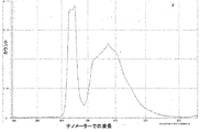
一般に言えば、本開示は、EMRを用いることによって電子アセンブリから部品を分離する方法に関する。EMRを発生する装置またはEMR源がここで提供される。EMRに含まれるフォトンは、影響を受けた分子の結合/化学における変化を引き起こす分子内の電子励起を開始することができる。EMRが電子アセンブリの外部の部品を通過すると、EMRは、外部の部品と内部の部品との間を接合する接着剤によって吸収される。EMR波のエネルギーは熱に変換され、その結果、EMRエネルギーを吸収する接着剤は素早く加熱されて溶解し又は除去さえもされる。その後、部品は容易に分離することができる。例えば、ディスプレイモジュールにおいてLOCAによって結合するカバーガラスからLCDを分離するために、カバーガラス側からEMRを適用し、カバーガラスを通じて伝わり、LOCAに部分的に吸収されるが、部分的に透過し、LCD上に施されたトップの偏光フィルムにあたり、また吸収される。そのため、LCDのトップの偏光子フィルムに対する接触部分においてLOCAで最高温度に達する。 Generally speaking, the present disclosure relates to a method of separating parts from an electronic assembly by using EMR. A device or EMR source for generating EMR is provided herein. The photons contained in the EMR can initiate intramolecular electronic excitation that causes a change in the binding / chemistry of the affected molecule. As the EMR passes through the external parts of the electronic assembly, the EMR is absorbed by the adhesive that bonds between the external and internal parts. The energy of the EMR wave is converted to heat, so that the adhesive that absorbs EMR energy is quickly heated to dissolve or even be removed. Thereafter, the parts can be easily separated. For example, to separate the LCD from the cover glass bonded by LOCA in the display module, EMR is applied from the cover glass side, transmitted through the cover glass and partially absorbed by LOCA, but partially transmitted by the LCD It hits the top polarizing film applied on top and is also absorbed. Therefore, the maximum temperature at LOCA is reached at the contact portion of the LCD top with the polarizer film.
ここで使用される用語「液体光学的透明接着剤」またはLOCAは、当技術分野において確立されており、当業者に知られている。種々の液体光学的透明接着剤が電気産業において、特にカバーガラス、プラスチックまたは他の光学材料、例えば透明プラスチックポリメチル(メタ)アクリレートを主のセンサーユニットまたは互いに接合するタッチパネルまたはディスプレイデバイスに対して、広く使用されている。液体光学的透明接着剤は、デバイスの光学特性を改善し、また他の特性、例えば耐久性を改善するために、一般に使用されている。液体光学的透明接着剤の使用の有用ないくつかの用途としては、静電容量タッチパネル、3Dテレビおよびガラスリターダー(glass retarders)が挙げられる。 The term “liquid optical clear adhesive” or LOCA as used herein is established in the art and known to those skilled in the art. Various liquid optical transparent adhesives are used in the electrical industry, especially for touchscreens or display devices that join cover glass, plastic or other optical materials such as transparent plastic polymethyl (meth) acrylate to the main sensor unit or to each other. Widely used. Liquid optically transparent adhesives are commonly used to improve the optical properties of the device and to improve other properties such as durability. Some useful applications for the use of liquid optical transparent adhesives include capacitive touch panels, 3D televisions and glass retarders.
特に、かかる接着剤は、少なくとも約85%、好ましくは少なくとも約90%の光学透過率を示す場合、光学的透明である。光学透過率の測定は一般的であり、当業者に既知である。例えば、液体光学的透明接着剤の光学透過率は、次の方法に従って約100μm厚のサンプルにおいて測定することができる:光学的透明接着剤の小液滴を、イソプロパノールを用いて3回拭き、その2端上に付けた、2つの約100μm厚のスペーサーテープを有する75mm×50mmの平面状マイクロスライド(Dow Corning, Midland, Ml製のガラススライド)上に配置する。第2のガラススライドを圧力下で接着剤上に付ける。次に、接着剤をUV源下で完全に硬化させる。Agilent製の分光計Cary 300を用いて光学透過率を波長380nm〜780nmから測定する。1つのブランクのガラススライドをバックグランドとして用いる。 In particular, such an adhesive is optically clear if it exhibits an optical transmission of at least about 85%, preferably at least about 90%. The measurement of optical transmission is common and is known to those skilled in the art. For example, the optical transmission of a liquid optical clear adhesive can be measured in a sample about 100 μm thick according to the following method: a small drop of optical clear adhesive is wiped three times with isopropanol and the Place on two 75 mm x 50 mm planar microslides (glass slides from Dow Corning, Midland, Ml) with two about 100 μm thick spacer tapes attached on two ends. A second glass slide is placed on the adhesive under pressure. The adhesive is then fully cured under a UV source. The optical transmittance is measured from a wavelength of 380 nm to 780 nm using an Agilent spectrometer Cary 300. One blank glass slide is used as the background.
本発明の特定の実施態様において、外部の部品を通過し、接着剤に吸収され、熱を発生する電磁照射は、約200nm〜約900nm、好ましくは約420nm〜約650nmの波長を有する。かかる電磁照射、特にUV-放射または可視光は、本方法の工程(a)によりEMRを発生する装置またはEMR源を用いてもたらされる。 In certain embodiments of the invention, the electromagnetic radiation that passes through the external components, is absorbed by the adhesive, and generates heat has a wavelength of about 200 nm to about 900 nm, preferably about 420 nm to about 650 nm. Such electromagnetic radiation, in particular UV-radiation or visible light, is provided using an apparatus or EMR source that generates EMR according to step (a) of the method.
ここで使用されるEMR源としては、特に限定されないが、高強度連続発生システム、例えばFusion UV Systemsから市販されるもの、メタルハライドランプ、LEDランプ、高圧水銀ランプ、キセノンランプ、キセノン閃光ランプ等が挙げられる。本発明の特定の実施態様において、EMRを発生する装置は好ましくは発光ダイオードの配列(LED)を含むように配置される。 The EMR source used here is not particularly limited, but includes high intensity continuous generation systems such as those commercially available from Fusion UV Systems, metal halide lamps, LED lamps, high pressure mercury lamps, xenon lamps, xenon flash lamps and the like. It is done. In certain embodiments of the invention, the device for generating EMR is preferably arranged to include an array of light emitting diodes (LEDs).
本発明に係る方法を適用する場合、EMR源は、通常は1mm〜5cm、好ましくは5〜10mmのエアーギャップでもって、電子デバイスの外部の部品、例えばディスプレイ/タッチモジュールのカバーガラスに近接して配置される。その後、照射はカバーガラスを通過し、液体光学的透明接着剤に伝わる。 When applying the method according to the invention, the EMR source is usually in the vicinity of components outside the electronic device, for example the cover glass of the display / touch module, with an air gap of 1-5 cm, preferably 5-10 mm. Be placed. The irradiation then passes through the cover glass and is transmitted to the liquid optical transparent adhesive.
別の特定の本発明の実施態様において、EMR源から発生されるEMRの強度は、約0.05W/cm2〜約5W/cm2、好ましくは約0.1W/cm2〜約3W/cm2である。 In another specific embodiment of the present invention, the intensity of the EMR generated from the EMR source is from about 0.05 W / cm 2 to about 5 W / cm 2 , preferably from about 0.1 W / cm 2 to about 3 W / cm 2 . is there.
本発明に係る方法の工程(c)において、内部の部品、例えばLCDに接着する接着剤は、EMR源からのEMRにより加熱され、そうして接着剤は約50℃〜約100℃、好ましくは約50℃〜約80℃の温度を有するように加熱される。 In step (c) of the method according to the invention, the adhesive that adheres to the internal components, for example the LCD, is heated by EMR from an EMR source, so that the adhesive is about 50 ° C. to about 100 ° C., preferably Heated to have a temperature of about 50 ° C to about 80 ° C.
液体光学的透明接着剤の温度を維持するために、照射の間、EMRの強度を変えてよい。例えば、5W/cm2の強度から開始し、接着剤の温度が80℃〜100℃に達した時に、EMRの強度は0.1W/cm2に下げられる。このように、接着剤の温度を一定に維持することができる。 In order to maintain the temperature of the liquid optical clear adhesive, the intensity of the EMR may be varied during irradiation. For example, starting from a strength of 5 W / cm 2 , the EMR strength is reduced to 0.1 W / cm 2 when the temperature of the adhesive reaches 80 ° C. to 100 ° C. In this way, the temperature of the adhesive can be kept constant.
また別の特定の本発明の実施態様において、EMR源による照射の時間は、約1秒〜約180秒、好ましくは約10秒〜約60秒である。 In yet another specific embodiment of the invention, the time of irradiation by the EMR source is from about 1 second to about 180 seconds, preferably from about 10 seconds to about 60 seconds.
本発明の方法によれば、電子デバイスにおけるEMR源の強度およびEMR時間の段階的な組み合わせにより、接着剤の加熱を得てもよい。例えば、25秒間、3W/cm2、次に15秒間、0.3W/cm2でEMRを伝えることによって接着剤層の温度を75℃〜80℃に一定に維持することができる。 According to the method of the present invention, heating of the adhesive may be obtained by a stepwise combination of the strength of the EMR source and the EMR time in the electronic device. For example, the temperature of the adhesive layer can be kept constant between 75 ° C. and 80 ° C. by delivering EMR at 3 W / cm 2 for 25 seconds and then at 0.3 W / cm 2 for 15 seconds.
本発明の別の実施態様において、本方法は、工程(c)と(d)との間において、約10〜30秒間、好ましくは約10〜20秒間、接着剤を冷却する工程(c1)をさらに含む。好ましくは、冷却工程は、室温(20℃〜25℃)の温度において空気中で電子アセンブリを配置することにより行われる。 In another embodiment of the invention, the method comprises the step (c1) of cooling the adhesive between steps (c) and (d) for about 10-30 seconds, preferably about 10-20 seconds. In addition. Preferably, the cooling step is performed by placing the electronic assembly in air at a temperature of room temperature (20 ° C. to 25 ° C.).
本発明の工程(c)または(c1)の後、工程(d)における部品の分離を、機械的負荷なしに又は非常に低い機械的負荷のいずれかにより行うことができる。 After step (c) or (c1) of the present invention, the separation of parts in step (d) can be performed either without mechanical load or with very low mechanical load.
機械的負荷なしとは、所望の部品、例えばLCDが自発的に接着剤および他の部品、例えばカバーガラスまたは偏光フィルムから分離されることを意味する。さらに、非常に低い機械的負荷によりとは、従来の分離方法、例えば加熱ワイヤカッティングによる処理無しまたは処理されたモジュールを分離するために必要な機械的負荷と比較して、手またはナイフ、ハサミ、クランプまたはくさび形ツール等の分割ツール(cleavage tool)により所望の部品、例えばLCDを接着剤および他の部品、例えばカバーガラスから容易に分離できることを意味する。 By no mechanical load is meant that the desired part, eg LCD, is spontaneously separated from the adhesive and other parts, eg cover glass or polarizing film. In addition, due to the very low mechanical load, the hand or knife, scissors, scissors, compared to the mechanical load required to separate conventional modules, for example, no processing by heated wire cutting or processed modules It means that a desired part, such as an LCD, can be easily separated from the adhesive and other parts, such as a cover glass, by means of a cleavage tool such as a clamp or wedge tool.
別の本発明の実施態様において、電子アセンブリからLCD等の部品の分離後、まだ外部の部品と接着する残る液体光学的透明接着剤フィルムを、WO 2014029062 A1に開示されるように外部の部品から剥がすことによりさらに洗浄してよい。 In another embodiment of the present invention, after separation of a component such as an LCD from an electronic assembly, the remaining liquid optical transparent adhesive film that still adheres to the external component is removed from the external component as disclosed in WO 2014029062 A1. You may wash | clean further by peeling.
驚くべきことに、発明者らは、EMRの波長、強度および時間、ならびにEMRを吸収する接着剤の温度等の、本発明に係る方法の種々のプロセスパラメーターを適当に選択することにより、機械的負荷が続く部品の分離に必要でない又は非常に低くなる程度まで、電子デバイスにおいて使用される接着剤、例えば光学的透明接着剤は溶融し、又は除去され、接着剤および他の部品からのターゲットの内部の部品、例えばLCDの好ましい解除を達成することができることを発見する。 Surprisingly, the inventors have found that by appropriately selecting the various process parameters of the method according to the invention, such as the EMR wavelength, strength and time, and the temperature of the adhesive that absorbs EMR. To the extent that it is not necessary or very low for the separation of parts that continue to be loaded, adhesives used in electronic devices, such as optically transparent adhesives, are melted or removed, and the target from the adhesive and other parts is removed. Discover that a favorable release of internal components, eg LCD, can be achieved.
本発明に係る方法は、その温度感受性により、当技術分野において従来使用されている加熱方法、例えば加熱ワイヤカッティング方法と比較して、本方法が非常に早く、分離された再利用される部品、例えばLCDを損傷しないという利点も有する。 Due to its temperature sensitivity, the method according to the present invention is very fast compared to the heating methods conventionally used in the art, such as the heating wire cutting method, the separated reusable parts, For example, it has the advantage of not damaging the LCD.
本発明に係る方法は、従来の方法と比較して、より安全であり、より効率的でもある。従来の方法において、熱が直接接触する源から来る場合、それは外部の層をまず加熱しなければならず、そして熱は伝導によって、より深層に移される。熱伝導は温度勾配が進行する必要があり、安全に使用できる最大温度(熱的保護グローブなしには約42℃)があるため、これは、加温が必要であるより低い温度を意味する。そのため、従来技術の方法の効率性は本発明に係る方法によりも非常に低い。 The method according to the present invention is safer and more efficient than conventional methods. In conventional methods, when heat comes from a source in direct contact, it must first heat the outer layer, and heat is transferred to deeper layers by conduction. This implies a lower temperature where warming is required because heat transfer requires a temperature gradient to progress and there is a maximum temperature that can be used safely (about 42 ° C. without thermal protection gloves). Therefore, the efficiency of the prior art method is much lower than that of the method according to the present invention.
本発明の方法によれば、EMRにより発生するエネルギーは、非常に厚い接触部分、例えばディスプレイモジュールのカバーレンズまたはエアーギャップ(または減圧)を通じてさえも、より容易に所望の接触部分に運ぶことができる。さらに、パラメーターの適当な組み合わせを選択することにより、外部の部品および接着剤の全域において均一で、場合により選択的な温度分布を達成することができる。 According to the method of the present invention, the energy generated by EMR can be more easily carried to the desired contact portion, even through a very thick contact portion, for example through the cover lens or air gap (or reduced pressure) of the display module. . Furthermore, by selecting an appropriate combination of parameters, a uniform and possibly selective temperature distribution can be achieved across the external parts and adhesive.
本発明による方法および設備は、3Dまたはコンプレックス成形ディスプレイモジュールに対して効率的にフィットすることもできる。 The method and equipment according to the invention can also be fitted efficiently to 3D or complex molded display modules.
図2および3は、電子アセンブリから部品を分離する前記方法に使用されるデバイス1を示す。表示の実施態様において、レンズ10が電子アセンブリから分離されており、これは示されていない。デバイス1は、筺体および多数の冷却フィン9を含む。レンズ10が2つの平面状接触表面8と接触するように、デバイス1はレンズ10に取り付けられる。さらにデバイス1は、電磁照射を発生する多数の第1の発光ダイオード2を含む。これらの第1の発光ダイオード2は、主発光ダイオードボード3上において平面で互いに一定間隔で配置される。主発光ボード3は2つの接触表面8の間に配置され、ここで、接触表面8の外部表面は、主発光ダイオードボード3に関してより高いレベルである。さらに、第2の発光ダイオード4は、互いに一定間隔で右側発光ダイオードボード5上に配置され、ここで、右側発光ダイオードボード5は主発光ダイオードボード3に対して傾斜して配置される。表示の実施態様において、右側発光ダイオードボード5は、右接触表面8の側壁上に主発光ダイオードボード3に対して傾斜して配置される。右側発光ダイオードボード5に対して反対側上に、さらに第3の発光ダイオード6が左側発光ダイオードボード7上に互いに一定間隔で配置され、ここで、左側発光ダイオードボード7は主発光ダイオードボード3に対して傾斜して配置される。表示の実施態様において、左側発光ダイオードボード7は左接触表面8の側壁上に主発光ダイオードボード3に対して垂直に配置される。個々の発光ダイオード2、4、6の周囲のボード部分3、5、7は、発光ダイオード2、4、6により発生し、レンズ10により反射される電磁波がまた反射されるように、少なくとも部分的に設計される。さらに、筺体の部分およびまたレンズ10に対する接触表面8は、研磨アルミニウムからなり、レンズ10によりまた反射される電磁波を反射する。
2 and 3 show the
本発明は次の実施例を参照し、より良く理解される。 The invention will be better understood with reference to the following examples.
実施例
実施例1
LCDで4.3を有し、カバーレンズおよびLCDモジュールの間に硬化リワーク性液体光学的透明接着剤の層が積層された、ディスプレイモジュールを、この実施例においてテストした。積層ディスプレイモジュールのカバーレンズをジグに固定した。図1に示すように420nm〜650nmの可視光範囲におけるLED配列を含むEMR源からのEMRを、レンズ側から3W/cm2の強度で適用し、カバーレンズおよびEMR源のエアーギャップは5mmである。EMRはカバーレンズを透過し、カバーレンズおよびLCDモジュールの間を接合する光学的透明接着剤に伝えられた。光がLCDに適用されたトップの偏光フィルムに達した時に吸収が最も高くなった。次のプログラムによりEMR源の強度を調整することにより温度を75℃〜80℃に一定に維持した:3W/cm2、25秒間、その後0.3W/cm2、15秒間。
Example <br/> Example 1
A display module having an LCD of 4.3 and having a layer of cured reworkable liquid optical clear adhesive laminated between the cover lens and the LCD module was tested in this example. The cover lens of the multilayer display module was fixed to the jig. As shown in FIG. 1, EMR from an EMR source including an LED array in the visible light range of 420 nm to 650 nm is applied with an intensity of 3 W / cm 2 from the lens side, and the air gap between the cover lens and the EMR source is 5 mm. . The EMR passed through the cover lens and was transferred to an optically clear adhesive that bonded between the cover lens and the LCD module. The absorption was highest when the light reached the top polarizing film applied to the LCD. The temperature was kept constant between 75 ° C. and 80 ° C. by adjusting the intensity of the EMR source with the following program: 3 W / cm 2 for 25 seconds, then 0.3 W / cm 2 for 15 seconds.
温度が一定に維持される間、ディスプレイモジュールの1つのコーナーにおいて挿入された特定のくさび形のツールにより形成された非常に低い機械的裂け目を用いてLCDモジュールを分離した。LCDモジュールはカバーレンズからうまく分離され、LCDモジュールおよびカバーレンズの表面は両方、接着剤残存物を含む。 While the temperature was kept constant, the LCD module was separated using a very low mechanical tear formed by a specific wedge-shaped tool inserted at one corner of the display module. The LCD module is well separated from the cover lens, and both the LCD module and cover lens surfaces contain adhesive residue.
実施例2
LCDで4.3を有し、カバーレンズおよびLCDモジュールの間に硬化リワーク性液体光学的透明接着剤の層が積層された、ディスプレイモジュールを、この実施例においてテストした。積層ディスプレイモジュールのカバーレンズをジグに固定した。図1に示すように420nm〜650nmの可視光範囲におけるLED配列を含むEMR源からのEMRを、レンズ側から3W/cm2の強度で適用し、カバーレンズおよびEMR源のエアーギャップは5mmである。EMRはカバーレンズを透過し、カバーレンズおよびLCDモジュールの間を接合する光学的透明接着剤に伝えられた。光がLCDに適用されたトップの偏光フィルムに達した時に吸収が最も高くなった。次のプログラムによりEMR源の強度を調整することにより温度を75℃〜80℃に一定に維持した:3W/cm2、25秒間、その後0.3W/cm2、15秒間。
Example 2
A display module having an LCD of 4.3 and having a layer of cured reworkable liquid optical clear adhesive laminated between the cover lens and the LCD module was tested in this example. The cover lens of the multilayer display module was fixed to the jig. As shown in FIG. 1, EMR from an EMR source including an LED array in the visible light range of 420 nm to 650 nm is applied with an intensity of 3 W / cm 2 from the lens side, and the air gap between the cover lens and the EMR source is 5 mm. . The EMR passed through the cover lens and was transferred to an optically clear adhesive that bonded between the cover lens and the LCD module. The absorption was highest when the light reached the top polarizing film applied to the LCD. The temperature was kept constant between 75 ° C. and 80 ° C. by adjusting the intensity of the EMR source with the following program: 3 W / cm 2 for 25 seconds, then 0.3 W / cm 2 for 15 seconds.
EMRを中断し、ディスプレイモジュールを20秒間、室温(20℃〜25℃)、空気中に配置した後に、ディスプレイモジュールの1つのコーナーにおいて挿入された特定のくさび形のツールにより形成された非常に低い機械的裂け目を用いてLCDモジュールを分離した。 Very low formed by a specific wedge shaped tool inserted at one corner of the display module after interrupting EMR and placing the display module in air for 20 seconds at room temperature (20 ° C to 25 ° C) The LCD module was separated using a mechanical tear.
20秒の冷却時間の間、外部から内部に熱拡散を行った。光学的透明接着剤層における最高温度を、接着剤およびトップの偏光フィルムの間の接触部分において維持し、その結果、LCDは、目視検査によるLCD表面上の接着剤残存物なく、カバーレンズからうまく分離され、接着剤はカバーレンズ上に残るのみである。 Thermal diffusion was performed from outside to inside during a cooling time of 20 seconds. The highest temperature in the optically clear adhesive layer is maintained at the contact between the adhesive and the top polarizing film, so that the LCD is well out of the cover lens without any adhesive residue on the LCD surface by visual inspection. Once separated, the adhesive only remains on the cover lens.
実施例1および2に示されるように、本発明の方法によれば、非常に低い機械的負荷によるディスプレイモジュール中のカバーガラスからのLCDの分離をより容易に達成することができる。驚くべきことに、冷却工程を含む実施例2の方法において、接着剤およびLCDの間の好ましい解除接触が達成され、実施例2で生じたLCDの表面には接着剤は残らなかった。 As shown in Examples 1 and 2, according to the method of the present invention, the separation of the LCD from the cover glass in the display module with a very low mechanical load can be achieved more easily. Surprisingly, in the method of Example 2 including a cooling step, a preferred release contact between the adhesive and the LCD was achieved, leaving no adhesive on the surface of the LCD produced in Example 2.
本発明の精神および範囲から離れずに、この本発明および他の修正および変形は当業者により実行され得る。また、種々の実施態様の態様は全体または部分的に置き換えてよいと理解されるべきである。さらに当業者は、上述の記載は例示のみであり、かかる添付の請求項に記載される発明を限定することを意図しないと理解するであろう。 This invention and other modifications and variations can be made by those skilled in the art without departing from the spirit and scope of the invention. In addition, it should be understood that aspects of the various embodiments may be interchanged in whole or in part. Further, those skilled in the art will appreciate that the above description is illustrative only and is not intended to limit the invention described in the appended claims.
1 デバイス
2 第1の発光ダイオード
3 主発光ダイオードボード
4 第2の発光ダイオード
5 右側発光ダイオードボード
6 第3の発光ダイオード
7 左側発光ダイオードボード
8 筺体
9 冷却フィン
10 レンズ
1 device
2 First light emitting diode
3 Main light emitting diode board
4 Second light emitting diode
5 Right LED board
6 Third light emitting diode
7 Left LED board
8 enclosure
9 Cooling fin
10 lenses
Claims (11)
(b)接着剤により内部の部品と接合された外部の部品を通して前記装置から電磁照射を放射する工程、ここで電磁照射の時間は10秒〜60秒である;
(c)電磁照射し、電磁照射を吸収させることによって接着剤を加熱し、接着剤の温度を約50℃〜約100℃、好ましくは約50℃〜約80℃に高める工程;および
(d)電子アセンブリから部品を分離する工程
を含み、
工程(c)と(d)との間において、10〜30秒間、接着剤を冷却する工程(c1)、好ましくは20℃〜25℃の温度において空気中で電子アセンブリを配置することにより行われる工程、をさらに含む、電子アセンブリから部品を分離する方法。 (A) A number of light emitting diodes are used to generate electromagnetic irradiation, the wavelength of electromagnetic irradiation is 420 nm to 650 nm, and the intensity of electromagnetic irradiation is 0.05 W / cm 2 to 5 W / cm 2 , preferably a 0.1W / cm 2 ~3W / cm 2 , the step of providing a device for generating electromagnetic radiation;
(B) radiating electromagnetic radiation from the device through an external component joined to an internal component with an adhesive, wherein the electromagnetic irradiation time is between 10 seconds and 60 seconds;
(C) applying electromagnetic radiation and heating the adhesive by absorbing electromagnetic radiation to raise the temperature of the adhesive to about 50 ° C. to about 100 ° C., preferably about 50 ° C. to about 80 ° C .; and (d) viewing including the step of separating the parts from electronic assembly,
Between steps (c) and (d), the step (c1) of cooling the adhesive for 10 to 30 seconds, preferably by placing the electronic assembly in air at a temperature of 20 ° C. to 25 ° C. step, further including a method for separating the part from the electronic assembly.
Applications Claiming Priority (1)
| Application Number | Priority Date | Filing Date | Title |
|---|---|---|---|
| PCT/CN2014/078977 WO2015180156A1 (en) | 2014-05-30 | 2014-05-30 | A process and apparatus for detaching a display module bonded by a liquid optically clear adhesive |
Publications (2)
| Publication Number | Publication Date |
|---|---|
| JP2017524989A JP2017524989A (en) | 2017-08-31 |
| JP6473806B2 true JP6473806B2 (en) | 2019-02-20 |
Family
ID=54697933
Family Applications (1)
| Application Number | Title | Priority Date | Filing Date |
|---|---|---|---|
| JP2017514750A Active JP6473806B2 (en) | 2014-05-30 | 2014-05-30 | Method and apparatus for separating display modules joined by a liquid optically transparent adhesive |
Country Status (8)
| Country | Link |
|---|---|
| US (1) | US10308841B2 (en) |
| EP (1) | EP3149096B1 (en) |
| JP (1) | JP6473806B2 (en) |
| KR (1) | KR102182434B1 (en) |
| CN (1) | CN106414636B (en) |
| ES (1) | ES2806259T3 (en) |
| TW (1) | TWI605949B (en) |
| WO (1) | WO2015180156A1 (en) |
Families Citing this family (2)
| Publication number | Priority date | Publication date | Assignee | Title |
|---|---|---|---|---|
| HUE051753T2 (en) * | 2017-01-26 | 2021-03-29 | Gross Leander Kilian | Method and device for separating different material layers of a composite component |
| KR102080103B1 (en) * | 2019-11-29 | 2020-02-24 | 주식회사 그린자이언트 | Separating method of display device |
Family Cites Families (26)
| Publication number | Priority date | Publication date | Assignee | Title |
|---|---|---|---|---|
| JP2707189B2 (en) * | 1992-08-26 | 1998-01-28 | 株式会社日立製作所 | Method and apparatus for removing electronic component from substrate |
| WO1997039611A1 (en) * | 1996-04-16 | 1997-10-23 | Matsushita Electric Industrial Co., Ltd. | Method and device for removing ic component |
| US7498065B2 (en) * | 2003-01-09 | 2009-03-03 | Con-Trol-Cure, Inc. | UV printing and curing of CDs, DVDs, Golf Balls And Other Products |
| GB0307504D0 (en) * | 2003-04-01 | 2003-05-07 | Debonding Ltd | Method and apparatus for bonding and debonding adhesive interface surfaces |
| KR20050116838A (en) | 2003-04-01 | 2005-12-13 | 디-본딩 리미티드 | Method and apparatus for bonding and debonding adhesive interface surfaces |
| JP4779346B2 (en) * | 2004-02-05 | 2011-09-28 | トヨタ自動車株式会社 | Fuel cell disassembly method |
| CN101167084B (en) * | 2005-04-28 | 2010-05-12 | 吉田健治 | Information I/O method using dot pattern |
| US8586204B2 (en) * | 2007-12-28 | 2013-11-19 | Universal Display Corporation | Phosphorescent emitters and host materials with improved stability |
| US20100297829A1 (en) * | 2006-07-05 | 2010-11-25 | The Arizona Board Of Regents, A Body Corporate Acting For And On Behalf Of Arizona State Unversit | Method of Temporarily Attaching a Rigid Carrier to a Substrate |
| JP5171425B2 (en) * | 2007-10-22 | 2013-03-27 | 日東電工株式会社 | Heat-foaming type removable acrylic pressure-sensitive adhesive tape or sheet, and peeling method |
| JP4471003B2 (en) * | 2008-01-23 | 2010-06-02 | セイコーエプソン株式会社 | Method for forming joined body |
| US8869419B2 (en) * | 2009-02-13 | 2014-10-28 | Soliduv, Inc. | Efficient irradiation system using curved reflective surfaces |
| JP5350056B2 (en) * | 2009-04-14 | 2013-11-27 | 電気化学工業株式会社 | Photo-curable easy-to-disassemble adhesive and disassembly method using the same |
| EP2517268B1 (en) * | 2009-12-23 | 2018-07-04 | Heraeus Noblelight Fusion UV Inc. | Uv led based lamp for compact uv curing lamp assemblies |
| JP5731137B2 (en) * | 2010-06-15 | 2015-06-10 | 電気化学工業株式会社 | Method of dismantling the bonded body by excimer light irradiation |
| CN103080258B (en) * | 2010-09-01 | 2015-01-21 | 电气化学工业株式会社 | Method for disassembling bonded body, and adhesive |
| JP5916620B2 (en) * | 2010-11-18 | 2016-05-11 | デンカ株式会社 | Method for peeling translucent hard substrate laminate and method for producing plate product using the same |
| KR101837227B1 (en) * | 2011-01-07 | 2018-03-09 | 인텔 코포레이션 | Release device, release system, release method, and computer storage medium |
| US8858756B2 (en) * | 2011-10-31 | 2014-10-14 | Masahiro Lee | Ultrathin wafer debonding systems |
| JP2013190496A (en) * | 2012-03-12 | 2013-09-26 | Nitto Denko Corp | Method for manufacturing flat panel display |
| WO2013173977A1 (en) * | 2012-05-22 | 2013-11-28 | Henkel (China) Company Limited | Process for binding substrates with a liquid optically clear photo-curable adhesive |
| KR20150046044A (en) | 2012-08-20 | 2015-04-29 | 헨켈 차이나 컴퍼니 리미티드 | Liquid optically clear photo-curable adhesive for display application |
| KR101922118B1 (en) * | 2012-08-27 | 2018-11-26 | 삼성전자주식회사 | Flexible semiconductor device and method of manufacturing the same |
| US20150107762A1 (en) * | 2013-10-18 | 2015-04-23 | Avery Dennison Corporation | Processes for the Removal of Labels from Materials |
| US10265939B2 (en) * | 2013-11-22 | 2019-04-23 | Tecna S.P.A. | Method and associated unit for removing plate-like elements |
| SG10201603100XA (en) * | 2016-04-19 | 2017-11-29 | Singapore Polytechnic | Method and apparatus for separating a component from a thermoset polymer adhered to the component |
-
2014
- 2014-05-30 WO PCT/CN2014/078977 patent/WO2015180156A1/en active Application Filing
- 2014-05-30 EP EP14892948.2A patent/EP3149096B1/en active Active
- 2014-05-30 KR KR1020167033406A patent/KR102182434B1/en active IP Right Grant
- 2014-05-30 US US15/313,268 patent/US10308841B2/en active Active
- 2014-05-30 ES ES14892948T patent/ES2806259T3/en active Active
- 2014-05-30 JP JP2017514750A patent/JP6473806B2/en active Active
- 2014-05-30 CN CN201480079431.XA patent/CN106414636B/en active Active
-
2015
- 2015-05-20 TW TW104115990A patent/TWI605949B/en not_active IP Right Cessation
Also Published As
| Publication number | Publication date |
|---|---|
| US10308841B2 (en) | 2019-06-04 |
| ES2806259T3 (en) | 2021-02-17 |
| TWI605949B (en) | 2017-11-21 |
| CN106414636A (en) | 2017-02-15 |
| US20170183541A1 (en) | 2017-06-29 |
| EP3149096A1 (en) | 2017-04-05 |
| JP2017524989A (en) | 2017-08-31 |
| KR20170015304A (en) | 2017-02-08 |
| TW201601863A (en) | 2016-01-16 |
| WO2015180156A1 (en) | 2015-12-03 |
| KR102182434B1 (en) | 2020-11-24 |
| EP3149096A4 (en) | 2017-12-13 |
| CN106414636B (en) | 2020-04-14 |
| EP3149096B1 (en) | 2020-06-24 |
Similar Documents
| Publication | Publication Date | Title |
|---|---|---|
| JP2016130810A (en) | Substrate for liquid crystal display panel | |
| CN1818754A (en) | Bonding method and apparatus | |
| CN104097382B (en) | The device of the cooling adhesive layer for showing equipment and the method for detaching panel | |
| US7896053B2 (en) | Non-destructive component separation using infrared radiant energy | |
| JP6473806B2 (en) | Method and apparatus for separating display modules joined by a liquid optically transparent adhesive | |
| JP2010197448A (en) | Method of manufacturing polarizing plate | |
| JP2022069475A (en) | Carrier release | |
| TWI655045B (en) | Disconnecting device for patterned substrate | |
| JP2009031781A (en) | Arrangement structure for optical member | |
| JP2017058394A (en) | Display device and method for manufacturing display device | |
| TWI443173B (en) | Touch-controlled display device and its manufacturing method | |
| TWI454762B (en) | Method of manufacturing light guide plate | |
| WO2013031051A1 (en) | Method for dismantling plasma display device | |
| US7593076B2 (en) | Optical device and method for manufacturing optical device | |
| Kim et al. | Effects of Ultraviolet Wavelength and Ambient Temperature on Reliability of Silicones in InAlGaN-Based Light-Emitting-Diode Package | |
| KR20210032911A (en) | Circular polarization plate | |
| WO2013031052A1 (en) | Method for dismantling plasma display device | |
| JP2007127772A (en) | Display device | |
| TWI549578B (en) | Method for reworking electronic device | |
| JPWO2013057852A1 (en) | Display device disassembly method and disassembly device | |
| US8715026B2 (en) | Method for disassembling plasma display device | |
| JP2015225224A (en) | Electronic device | |
| JP2008051995A (en) | Optical element and manufacturing method of optical element | |
| US20150185070A1 (en) | Photoelectric converting module and method for assembling same | |
| KR20030056234A (en) | The separation method and the same apparatus of the radiating plate for the Plasma Display Panel |
Legal Events
| Date | Code | Title | Description |
|---|---|---|---|
| A131 | Notification of reasons for refusal |
Free format text: JAPANESE INTERMEDIATE CODE: A131 Effective date: 20180327 |
|
| A521 | Request for written amendment filed |
Free format text: JAPANESE INTERMEDIATE CODE: A523 Effective date: 20180625 |
|
| A131 | Notification of reasons for refusal |
Free format text: JAPANESE INTERMEDIATE CODE: A131 Effective date: 20180905 |
|
| A521 | Request for written amendment filed |
Free format text: JAPANESE INTERMEDIATE CODE: A523 Effective date: 20181204 |
|
| TRDD | Decision of grant or rejection written | ||
| A01 | Written decision to grant a patent or to grant a registration (utility model) |
Free format text: JAPANESE INTERMEDIATE CODE: A01 Effective date: 20190108 |
|
| A61 | First payment of annual fees (during grant procedure) |
Free format text: JAPANESE INTERMEDIATE CODE: A61 Effective date: 20190128 |
|
| R150 | Certificate of patent or registration of utility model |
Ref document number: 6473806 Country of ref document: JP Free format text: JAPANESE INTERMEDIATE CODE: R150 |
|
| R250 | Receipt of annual fees |
Free format text: JAPANESE INTERMEDIATE CODE: R250 |
|
| R250 | Receipt of annual fees |
Free format text: JAPANESE INTERMEDIATE CODE: R250 |
|
| R250 | Receipt of annual fees |
Free format text: JAPANESE INTERMEDIATE CODE: R250 |