JP6473771B2 - Storage - Google Patents
Storage Download PDFInfo
- Publication number
- JP6473771B2 JP6473771B2 JP2017058068A JP2017058068A JP6473771B2 JP 6473771 B2 JP6473771 B2 JP 6473771B2 JP 2017058068 A JP2017058068 A JP 2017058068A JP 2017058068 A JP2017058068 A JP 2017058068A JP 6473771 B2 JP6473771 B2 JP 6473771B2
- Authority
- JP
- Japan
- Prior art keywords
- side wall
- wall portion
- region
- cover
- holding body
- Prior art date
- Legal status (The legal status is an assumption and is not a legal conclusion. Google has not performed a legal analysis and makes no representation as to the accuracy of the status listed.)
- Active
Links
Images


Landscapes
- Sheet Holders (AREA)
Description
本開示は、書類等を収納する収納具に関する。 The present disclosure relates to a storage device that stores documents and the like.
従来、書類等の紙状体を収納する収納具として、種々の収納具が使用されている。収納具は、例えば、開口を有する箱状をなしており、開口から書類等を入れることにより、収納する。ここで、収納具は、書類の分量に応じて、全体の大きさを調整可能なように、対向する2枚の表紙部を蛇腹状の側面部により接続する場合がある(例えば、特許文献1参照)。 Conventionally, various storage tools are used as storage tools for storing paper-like objects such as documents. The storage tool has, for example, a box shape having an opening, and stores a document by inserting a document or the like through the opening. Here, the storage tool may connect two facing cover parts by a bellows-like side part so that the overall size can be adjusted according to the amount of documents (for example, Patent Document 1). reference).
この場合、2枚の表紙部間に挟まれる書類等が少ない場合又は使用せずに保管しておく場合、側面部を折りたたんで、全体の大きさを小さくしておき、種類等が多い場合、側面部の伸長により、より多くの書類を収容する。 In this case, when there are few documents sandwiched between the two cover parts or when storing them without using them, folding the side parts to reduce the overall size, there are many types, etc. Accommodates more documents by extending the sides.
しかしながら、側面部は、縮小した状態においては、書類等を入れにくいため、伸長した状態を保持する場合があるが、この状態を保持しつつ、書類等を収容する作業は煩雑であるという問題がある。 However, since the side portion is difficult to insert a document or the like in a reduced state, the side portion may be held in an expanded state. However, there is a problem that the operation of storing the document or the like is complicated while maintaining this state. is there.
本開示は、斯かる事情に鑑みてなされたものであり、その目的とするところは、容易に収納作業を行うことができる収納具を提供することにある。 The present disclosure has been made in view of such circumstances, and an object of the present disclosure is to provide a storage tool that can be easily stored.
本開示の一実施形態に係る収納具は、一面に開口が設けられた箱状をなし、物品を収納する収納具において、対向する第1側壁部及び第2側壁部と前記第1側壁部及び第2側壁部に連なり、前記第1側壁部及び第2側壁部の対向方向に伸縮可能である2つの第3側壁部と、前記第1側壁部及び第2側壁部に連なり、前記対向方向に伸縮可能である底壁部と、前記第1側壁部及び第2側壁部の対向距離を所定距離に保持し、前記第1側壁部又は第2側壁部から着脱可能である保持体とを備えることを特徴とする。 A storage device according to an embodiment of the present disclosure has a box shape with an opening provided on one surface thereof. In the storage device that stores articles, the first side wall portion, the second side wall portion, the first side wall portion, Two third side wall portions that are connected to the second side wall portion and can be expanded and contracted in the opposing direction of the first side wall portion and the second side wall portion, and are connected to the first and second side wall portions and in the opposing direction. A bottom wall portion that can be expanded and contracted, and a holding body that holds a facing distance between the first side wall portion and the second side wall portion at a predetermined distance and is detachable from the first side wall portion or the second side wall portion. It is characterized by.
本開示の一実施形態によれば、保持体により第1側壁部及び第2側壁部を接続することにより、第1側壁部及び第2側壁部を所定距離に保持することができる。したがって、第2側壁部及び底壁部を伸長した状態を維持でき、開口を広げた状態を維持できる。したがって、容易に収納作業を行うことができる。 According to one embodiment of the present disclosure, the first side wall and the second side wall can be held at a predetermined distance by connecting the first side wall and the second side wall with the holding body. Therefore, the state which extended the 2nd side wall part and the bottom wall part can be maintained, and the state which extended the opening can be maintained. Therefore, the storing operation can be easily performed.
本開示の一実施形態に係る収納具は、前記保持体は、一方向に長い板状をなし、前記保持体の一端部は、前記第1側壁部又は前記第2側壁部の一方に着脱可能に接続され、前記保持体の他端部は、前記第1側壁部又は前記第2側壁部の他方に前記第2側壁部に支持されていることを特徴とする。 In the storage device according to an embodiment of the present disclosure, the holding body has a plate shape that is long in one direction, and one end of the holding body is detachable from one of the first side wall and the second side wall. The other end of the holding body is supported by the second side wall on the other of the first side wall or the second side wall.
本開示の一実施形態によれば、保持体の一端部を第1側壁部又は第2側壁部から着脱することにより、第1側壁部及び第2側壁部の対向距離を所定距離に保持すること及びその解除が可能となる。 According to one embodiment of the present disclosure, the opposing distance between the first side wall and the second side wall is held at a predetermined distance by attaching and detaching one end of the holding body from the first side wall or the second side wall. And the cancellation thereof.
本開示の一実施形態に係る収納具は、前記第1側壁部又は前記第2側壁部に設けられ、前記保持体を挿脱可能に収容する収容体を備えることを特徴とする。 The storage tool which concerns on one Embodiment of this indication is provided in the said 1st side wall part or the said 2nd side wall part, and is provided with the storage body which accommodates the said holding body so that insertion or removal is possible.
本開示の一実施形態によれば、保持体を使用しない場合は、収容体に収容しておき、保持体が必要な場合に収容体から取り出して使用することができる。 According to an embodiment of the present disclosure, when the holding body is not used, the holding body can be stored in the housing body, and can be taken out from the housing body and used when the holding body is necessary.
本開示の一実施形態に係る収納具は、前記保持体は、複数あり、前記収容体は、前記複数の保持体を重ねて収容し、前記底壁部に平行に延び、前記保持体を移動可能に前記底壁部側から支持する支持部と、前記複数の保持体の位置を仕切る仕切り部とを有することを特徴とする。 The storage tool according to an embodiment of the present disclosure includes a plurality of the holding bodies, the storage body stores the plurality of holding bodies in an overlapping manner, extends in parallel with the bottom wall portion, and moves the holding body. It has the support part supported from the said bottom wall part side possible, and the partition part which partitions off the position of these holding bodies.
本開示の一実施形態によれば、支持部が移動可能に支持することにより、保持体の移動が移動の際に案内され、移動をスムーズにすることができる。また、仕切り部により、複数の保持体が互いに干渉しないため、移動をスムーズにすることができる。 According to one embodiment of the present disclosure, the support portion is movably supported, whereby the movement of the holding body is guided during the movement, and the movement can be made smooth. Further, since the plurality of holding bodies do not interfere with each other by the partition portion, the movement can be made smooth.
本開示の一実施形態に係る収納具は、前記収容体は、折り目が、前記底壁部に平行であり、前記底壁部側及び前記開口側に交互に位置するように複数回折り曲げられたシートにより形成され、前記支持部は、前記底壁部側に位置する折り目を形成する部分であることを特徴とする。 In the storage tool according to an embodiment of the present disclosure, the storage body is bent a plurality of times so that a fold is parallel to the bottom wall portion and is alternately positioned on the bottom wall portion side and the opening side. It is formed by a sheet, and the support part is a part which forms a crease located in the bottom wall part side.
本開示の一実施形態によれば、一の部材で、複数の支持部を形成することができ、部材点数を少なくし、また、構造が簡素になる。 According to one embodiment of the present disclosure, a plurality of support portions can be formed with one member, the number of members is reduced, and the structure is simplified.
本開示の一実施形態に係る収納具は、前記第1側壁部又は前記第2側壁部には、前記保持体の一端部が挿脱可能に挿入される挿入口が設けられていることを特徴とする。 The storage tool according to an embodiment of the present disclosure is characterized in that the first side wall or the second side wall is provided with an insertion port into which one end of the holding body is detachably inserted. And
本開示の一実施形態によれば、保持体の一端部を挿入口に挿入することにより、保持体を保持することができる。 According to one embodiment of the present disclosure, the holding body can be held by inserting one end of the holding body into the insertion port.
本開示の実施形態によれば、容易に収納作業を行うことができる。 According to the embodiment of the present disclosure, the storing operation can be easily performed.
以下、本開示に係る収納具についてその実施形態を示す図面に基づいて詳述する。
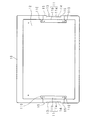
図1及び図2は、実施形態に係る収納具の外観斜視図である。図3は、収納具の側面図であり、図4は、収納具の底面図である。図1、図2、図3及び図4において、図示の100は、収納具であり、収納具100は、一面が開口した箱状をなし、矩形平板状の第1表紙部2及び第2表紙部3と、シート状の接続壁部3,3及び底壁部4と、シート状の複数の区切り体5,5,・・・(図では12枚)と、2つの矩形平板状のアーム6,6とを備える。
Hereinafter, the storage device according to the present disclosure will be described in detail based on the drawings illustrating an embodiment thereof.
FIG.1 and FIG.2 is an external appearance perspective view of the storage tool which concerns on embodiment. FIG. 3 is a side view of the storage tool, and FIG. 4 is a bottom view of the storage tool. 1, 2, 3, and 4,
第1表紙部1及び第2表紙部2は、平行に対向しており、各短辺部が接続壁部3,3により接続されている。底壁部4は、第1表紙部1及び第2表紙部2の対向面において対向する一に長辺部に接続され、接続壁部3,3における前記一の長辺部側の部分に連なっている。接続壁部3,3及び底壁部4は、夫々が、第1表紙部1及び第2表紙部2の対向方向に伸縮可能であるように蛇腹状に形成されている。接続壁部3,3及び底壁部4は、一枚の矩形状のシートを長手方向において折り曲げることにより形成されている。
The
各区切り体5は、収納具100の内部において、接続壁部3,3及び底壁部4の蛇腹形状の谷折りに係る部分に対応させて配されている。ここで、谷折りとは、収納具100の内側に折り目が位置するように折ることを指し、山折りとは収納具100の外側に折り目が位置するように折ることを指す。区切り体5は、例えば、周縁部を接続壁部3,3及び底壁部4に超音波溶着することにより固定されている。
Each
アーム6,6は、後述するように、第2表紙部2に挿脱可能に収容されており、図2に示すように第1表紙部1及び第2表紙部2を接続し、第1表紙部1及び第2表紙部2を接続した場合、第1表紙部1及び第2表紙部2の対向距離を所定距離に保持する。ここで、図1及び図4は、アーム6,6を収容した状態を示し、図2及び図3は、アーム6,6により、第1表紙部1及び第2表紙部2に接続している状態を示している。
As will be described later, the
図5は、第1表紙部1の平面図である。第1表紙部1は、本体部10、2つの折り返し部11,11及び被覆板12を有する。本体部10は矩形板状をなし、折返し部11,11は、本体部10の各短辺部の中央部分に設けられている。本体部10及び折返し部11,11は一枚の板により形成されている。
FIG. 5 is a plan view of the
図6は、折返し部11の折返し前の状態を示す説明図である。図7は、第1表紙部1の側面の一部を示す模式図ある。折り返し部11は、本体部の短辺に沿って長い板状をなしており、短手方向に並ぶ一端部11a及び他端部11bを有する。他端部11bの方が、一端部11aよりも長く形成されている。折り返し部11の一端部11aは、折り返し部11の長手方向に並ぶヒンジ部15,15を介して本体部10の短辺部10aに連なっている。ヒンジ部15,15は、例えば、いわゆるトムソン加工により形成されている。
FIG. 6 is an explanatory diagram illustrating a state before the
一端部11aには、ヒンジ部15,15間において、折返し部11側に凹む凹部13が設けられている。本体部10には、ヒンジ部15,15間において、凹部13に連なり、本体部10側に凹む凹部14が設けられている。
The one end portion 11 a is provided with a
折返し部11は、ヒンジ部15,15において、本体部10の一面側に折り曲げられ、本体部10の一面に重なっている。折返し部11の他端部11bの長手方向の各端部110,110において、例えば超音波溶着により、本体部10に溶着されている。これにより、図7に示すように、折り返し部11の凹部13及び本体部10の凹部14間には、隙間16が形成されている。隙間16に後述するアーム6の一端部61が挿入される。また、凹部14は、凹部13よりも深く形成されている。これにより、折返し部11が折り返された状態において、凹部13の縁部は凹部14から露出する。
The folded
ここで、第1表紙部1は、折返し部11が重なる一面を内側として配されている。第1表紙部1の一面の一の短辺部において、折り返し部11以外の部分が接続壁部3に接続されている。接続壁部3の第1表紙部1側の部分において、折り返し部11に対向する部分には、図3に示すように、内側に凹む凹部30が設けられている。折り返し部11は、凹部30と本体部10との間から露出している。第1表紙部1の一面の他の短辺部においても、同様の構造である。
Here, the
被覆板12は、本体部10の一面に該一面の周縁部を残して被せられている。被覆板12は、折返し部11の他端部11bを覆うように配され、被覆板12の周縁部は、本体部10の一面に、例えば超音波溶着により溶着されている。
The covering
図8は、第2表紙部2の平面図である。第2表紙部2は、本体部20、2つの折返し部21,21及び被覆板22を有する。本体部20は矩形板状をなし、折返し部21,21は、本体部20の各短辺部の中央部分に設けられている。
FIG. 8 is a plan view of the
図9は、第2表紙部2の構造を示す説明図である。図10は、第2表紙部2の側面の一部を示す模式図ある。折返し部21は、本体部20の短辺に沿って長い板状をなしており、短手方向に並ぶ一端部21a及び他端部21bを有する。一端側21aが本体部20の短辺部20aに、折返し部21の長手方向に並ぶヒンジ部25,25を介して本体部20に連なっている。ヒンジ部25,25は、例えば、いわゆるトムソン加工により形成されている。
FIG. 9 is an explanatory diagram showing the structure of the
折返し部21には、ヒンジ部25,25間において、折返し部21の側に凹む凹部23が設けられている。本体部20には、ヒンジ部25,25間において、凹部23に連なり、本体部20側に向けて凹む凹部24が設けられている。
The folded
折返し部21は、ヒンジ部25,25において、本体部20の一面側に折り曲げられ、本体部20の一面に重なっている。折返し部21の他端部21bの長手方向の各端部210,210は、例えば超音波溶着により、本体部20に溶着されている。これにより、図10に示すように、折返し部21の中央部及び本体部20の間には、隙間26が形成されている。隙間26において、後述するアーム6が移動する。また、凹部24は、凹部23よりも深く形成されている。これにより、折返し部21が折り返された状態において、凹部23の縁部は凹部24から露出する。
The folded
ここで、第2表紙部2は、折返し部21が重なる一面を内側として配されている。第2表紙部2の一面の一の短辺部において、折り返し部21以外の部分が接続壁部3に接続されている。接続壁部3の第2表紙部2側の部分において、折返し部21に対向する部分には、図3に示すように、内側に凹む凹部31が設けられている。折返し部21は、凹部32と本体部10との間から露出している。第2表紙部2の一面の他の短辺部においても、同様の構造である。
Here, the
被覆板22は、矩形状をなし、一の長辺部を本体部20の一の長辺部に沿わせて、本体部20に被せられている。被覆板22は、折返し部21の他端部21bを覆うように配され、被覆板22の前記一の長辺部は、本体部20の前記一の長辺部に溶着され、他の長辺部は、本体部20の一面に溶着されている。
The covering
被覆板22及び本体部20の間において、凹部23,23の間には、アーム6,6が収容され、アーム6,6を収容する収容体7が配されている。収容体7は、図9に示す一枚の四角形状のシートを後述するように、折り畳むことにより形成されている。収容体7は、広げられた状態における一辺側に位置する第1領域71、該第1領域71に連なる第2領域72、該第2領域に連なる第3領域73、該第3領域73に連なる第4領域74、及び該第4領域に連なる接続領域75を有する。接続領域75は、前記一辺の対辺側に位置する。
Between the
第1領域71、第2領域72、第3領域73及び第4領域74は、同形をなしており、前記一辺に沿って長く、該一辺に平行な矩形状をなしている。第1領域71〜第4領域74の長さは、本体部20よりも短い。接続領域75は、第1領域71〜第4領域74に平行であり、同じ長さの矩形状であり、短手方向の幅が、第1領域71〜第4領域74よりも小さい。
The
第1領域71には、長手方向の一端部から、該長手方向に沿って延びる延出部71aが設けられおり、第2領域72には、長手方向の他端部から、該長手方向に沿って延びる延出部72aが設けられている。第4領域74には、長手方向の一端部から、該長手方向に沿って延びる延出部74aが設けられている。延出部71a,73a,74aは、先端にかけて細くなるテーパ形状をなしている。第4領域74の長さは、延出部74aを含めて本体部20よりも短く、延出部20aは全体が本体部20に重なるように位置している。
The
収容体7は、第1領域71〜第4領域74及び接続領域75の長手方向が本体部20の長手方向に平行となり、接続領域75が、二つの折返し部21,21における一の側のヒンジ部25間に位置し、第1領域71〜第4領域74が前記一の側に位置するように配されている。接続領域75が本体部20の一面に、例えば、超音波溶着により接続されることにより、本体部20に固定されている。
In the
以下、収容体7の折り畳み態様について説明する。図11〜17は、収容体の折り畳み態様の説明図である。ここで、収容体7の折り畳み態様においては、一面側(図11〜17における紙面表側)に折り曲げることを谷折りとし、他面側(図11〜17における紙面裏側)に折り曲げることを山折りとする。
Hereinafter, the folding aspect of the
まず、図11に示すように、広げられた収容体7を、第1領域71及び第2領域72の境目部分において谷折りする。これにより、曲折部7aが形成される。次に、図12に示すように、延出部71aを山折りする。その後、図13に示すように、収容体7を第2領域72及び第3領域73の境目部分で山折りする。これにより、曲折部7bが形成される。
First, as shown in FIG. 11, the expanded
その後、図14に示すように、収容体7を第3領域73及び第4領域74の境目部分において、谷折りする。これにより、曲折部7cが形成される。その後、図15に示すように、延出部72aを山折りした後、図16に示すように、延出部74aを山折りする。最後に図17に示すように、第4領域74及び接続領域75の境目部分において、谷折りすることにより収容体7が折り畳まれた状態となる。このとき、接続部75側が本体部20側に位置している。
After that, as shown in FIG. 14, the
図18及び図19は、収容体7の構造を示す模式的断面図である。図18は、収容体7の長手方向の断面を示し、図19は、収容体7の短手方向の断面を示している。図18及び図19に示すように、アーム6の内、一方は第1領域71及び第2領域72間に収容され、他方は第3領域73及び第4領域74間に収容されている。これにより、2本のアーム6,6は、互いに干渉しない。
18 and 19 are schematic cross-sectional views showing the structure of the
また、折り曲げられた延出部71aの先端部は、第2領域72及び第3領域73間に挿入されている。折り曲げられた延出部72aの先端部は、第4領域74の外面上に位置している。ここで、収容体7の長手方向の各端部は、折返し部21及び本体部20により挟まれる。これにより、第1領域71と第2領域72との間において、延出部71a側は、折り曲げられた延出部71aにより蓋がされている。また、第3領域73及び第4領域74間において、延出部72a側は、折り曲げられた延出部72aにより蓋がされている。
Further, the bent distal end portion of the extending
したがって、第1領域71及び第2領域72間に収容されているアーム6は、延出部71a側からは挿脱されず、延出部71aの反対側から挿脱可能となる。第3領域73及び第4領域74間に収容されているアーム6は、延出部72a側からは挿脱されず、延出部72aの反対側から挿脱可能となる。これにより、2本のアーム6,6は、互いに収容体7の長手方向の反対側から挿脱可能となる。
Therefore, the
図19に示すように、収容体7に収容されているアーム6,6は、曲折部7cを形成する第2領域72及び第3領域により仕切られている。また、第2表紙部2は、曲折部7a,7bが底壁部4側に位置し、延出部71aが一方の接続壁部3側に位置し、延出部72aが他方の接続壁部3側に位置するように配されている。これにより、曲折部7a,7b,7cは、第2表紙部2の本体部20と、底壁部4に沿って平行に延び、底壁部4側と、収納具100の開口側に交互に位置することとなる。
As shown in FIG. 19, the
第1領域71及び第2領域72間に収容されているアーム6は、一の長辺部が曲折部7aに対向し、移動の際に曲折部7aに案内される。第3領域73及び第4領域74間に収容されているアーム6は、一の長辺部が曲折部7bに対向し、移動の際に曲折部7bに案内される。
The
以上において、曲折部7a,7bは、底壁部4に平行に延び、アーム6,6を移動可能に底壁部4側から支持する支持部をなし、第2領域72及び第3領域73は、複数のアーム6の位置を仕切る仕切り部をなす。したがって、収容体7は、折り目が、底壁部4に平行であり、底壁部4側及び開口側に交互に位置するように複数回折り曲げられたシートにより形成され、前記支持部は、前記底壁部4側に位置する折り目を形成する部分であり、前記仕切り部は、前記開口側に位置する折り目を形成する部分である。
In the above, the
図20は、アーム6の側面図である。図21は、図20のXXI−XXI線による断面図であり、図22は、図20のXXII−XXII線による断面図である。アーム6は、矩形状の本体部60と、本体部60の一端部に設けられた挿入部61と、本体部60の他端部に設けられた係止部62とを有する。
FIG. 20 is a side view of the
本体部60は、矩形状の第1板部60a及び第2板部60bにより形成されている。第1板部60a及び第2板部60bは、同じ方向に長く、長辺部同士がヒンジ部604を介して、連なっている。本体部60は、第1板部60a及び第2板部60bをヒンジ部604において折り曲げて、互いに重ね合わせることにより形成されている。第1板部60a及び第2板部60bは、例えば、超音波溶着により溶着されている。
The
第1板部60aの一端部には、挿入部61が短手方向に延びるヒンジ部601を介して連なっている。ヒンジ部601により、挿入部61が第2板部60b側に位置するように折り曲げが可能である。
The
第1板部60aの他端部には、係止部62が短手方向に延びるヒンジ部602を介して連なっている。ヒンジ部602の長手方向の中央部には、該長手方向に長い長孔603が貫設されている。ヒンジ部602により、係止部61が第2板部60b側に位置するように折り曲げが可能である。ここで、ヒンジ部601,602,604は、例えば、トムソン加工により形成されている。
The locking
第2板部60bの係止部62側の端部は、端部に向けて細くなるテーパ状をなしており、先端部610は、長孔603まで延びている。また、先端部610は、ヒンジ部602よりも係止部62側に位置している。先端部610は、アーム6がヒンジ部602において、折り曲げられた場合、長孔603から第1板部60a側に突出する。
The end portion of the
係止部62は、矩形状の接続板部62a及び係止板部62bにより形成されており、長辺部同士がヒンジ部620を介して連なっている。係止部62は、接続板部62a及び係止板部62bをヒンジ部620において折り曲げて、互いに重ね合わせることにより形成されている。ここで、係止板部62bは、第2板部60bの反対側に位置している。接続板部62a及び係止板部62bは、例えば、超音波溶着により溶着されている。
The locking
接続板部62aは、ヒンジ部620の反対側が本体部60の第1板部60aに連なっている。係止板部62bは、接続板部62aよりも長く、両端部621,621が接続板部62aから突出している。
The
アーム6は、第2板部60bが内側に位置し、係止板部62bが収容体7の延出部71a又は72a側に位置するように、収容体7に収容されている。このとき、挿入部61が図1に示すように、隙間26から露出している。
The
図23及び図24は、アーム6の使用態様を示す説明図である。アーム6は、図23に示すように、図1に示す状態からアーム6を、隙間26から露出している挿入部61側から引き出す。このとき、収容体7の曲折部7aがアーム6の移動を案内し、アーム6を収容体7からスムーズに取り出すことができる。アーム6の本体部60を全て引き出した場合、係止板部62bにおける両端部621,621がヒンジ部25,25に当接して係止され、アーム6の移動が規制される。
23 and 24 are explanatory views showing how the
アーム6の本体部60を引き出した後、図23に示すように、アーム6をヒンジ部602において折り曲げて接続壁部3の外面に近接させる。その後、アーム6をヒンジ部601において折り曲げ、挿入部61を第1表紙部1の隙間16に挿入することにより、図2に示すようにアーム6により、第1表紙部1及び第2表紙部2を接続することができる。
After the
アーム6の収容体7への収容は、挿入部61を第1表紙部1の隙間16から取り出し、ヒンジ部601及びヒンジ部602を曲折状態から戻し、隙間26から本体部60及び挿入部61を挿入することにより行われる。アーム6の隙間26における挿脱の際、先端部610がヒンジ部602よりも係止部62側に位置しているので、隙間26の縁部分に引っかかることを防止することができる。これにより、アーム6をスムーズに移動させることができる。
The
以上の如く構成された収納具100は、開口側から、使用者が、区切り体5,5間、第1表紙部2及び区切り体5間、第2表紙部3及び区切り体5間に適宜書類等を差し込むことにより使用される。また、収納具100を使用せずに棚などで保管する場合、第1表紙部1及び第2表紙部2を近接させることにより、接続壁部3,3及び底壁部4が収縮し収納具100を折りたたむことができ、省スペース化を図ることができる。
The
第1表紙部1及び第2表紙部2を離隔するように移動させることにより、接続壁部3,3及び底壁部4が伸長し、区切り体5,5間と、第1表紙部2及び区切り体5間と、第2表紙部3及び区切り体5間との間隔が広がる。これにより、収納具に収納される書類等が増加した場合にも、より多くの書類等を収納することができる。
By moving the
このとき、アーム6,6を上述するように使用することにより、第1表紙1及び第2表紙2を接続し、第1表紙部1及び第2表紙部2の対向距離を一定に保持し、接続壁部3,3及び底壁部4が伸長した状態を保つことができる。これにより、区切り体5,5間、第1表紙部2及び区切り体5間、第2表紙部3及び区切り体5間の間隔を広げた状態を保持でき、使用者は、容易に収納作業を行うことができる。
At this time, by using the
以上の構成によれば、アーム6,6により第1表紙部1及び第2表紙部2を接続することにより、第1表紙部1及び第2表紙部2に対向距離を所定距離に保持することができる。したがって、接続壁部3,3及び底壁部4を伸長した状態を維持でき、収納具100開口を広げた状態を維持できる。したがって、収納具100の使用者は容易に収納作業を行うことができる。
According to the above configuration, the
また、アーム6,6を使用しない場合は、収容体7に収容しておき、アーム6,6が必要な場合に収容体7から取り出して使用することができる。曲折部7a,7bがアーム6,6を移動可能に支持することにより、アーム6,6が移動の際に案内され、移動をスムーズにすることができ。また、第2領域72及び第3領域73により、アーム6,6が互いに干渉しないため、移動をスムーズにすることができる。
Further, when the
更に、曲折部7a,7bと、第2領域72第3領域73とは、一枚のシートに含まれているので、収納具100の部材点数少なくでき、また、構造を簡素にすることができる。アーム6の挿入部61を隙間16に挿入することにより、アーム6を保持することができる。アーム6の中央部は第1板部60a及び第2板部60bを重ねて形成されているので、アーム6が変形しにくくなり、良好に第1表紙部1及び第2表紙部2の対向距離を保持することができる。
Further, since the
なお、アーム6の本体部60は、テレスコピック形状にして、長さ調整を可能とした構造であってもよい。また、ヒンジ部は、トムソン加工により形成する構成に限られず、いわゆる熱ヒンジその他の構成であってもよい。更に、アーム6の本体部60は、一枚の板状部材により形成することとしてもよい。また、各部材における溶着は、超音波溶着に限られず、例えば、熱溶着により行ってもよい。
The
今回開示された実施の形態はすべての点で例示であって、制限的なものではないと考えられるべきである。本発明の範囲は、上記した意味ではなく、特許請求の範囲によって示され、特許請求の範囲と均等の意味及び範囲内でのすべての変更が含まれることが意図される。即ち、請求項に示した範囲で適宜変更した技術的手段を組み合わせて得られる実施形態も本発明の技術的範囲に含まれる。 The embodiment disclosed this time is to be considered as illustrative in all points and not restrictive. The scope of the present invention is defined by the terms of the claims, rather than the meanings described above, and is intended to include any modifications within the scope and meaning equivalent to the terms of the claims. That is, embodiments obtained by combining technical means appropriately changed within the scope of the claims are also included in the technical scope of the present invention.
1 第1表紙部(第1側壁部、第2側壁部)
16 隙間(挿入口)
2 第2表紙部(第1側壁部、第2側壁部)
3 接続壁部(第3側壁部)
4 底壁部
6 アーム(保持体)
60 本体部(中央部)
60a 第1板部(板状体)
60b 第2板部(板状体)
61 挿入部(一端部)
62 係止部(他端部)
7 収容体
7a,7b 曲折部(支持部)
72 第2領域(仕切り部)
73 第3領域(仕切り部)
100 収納具
1 1st cover part (1st side wall part, 2nd side wall part)
16 Clearance (insertion slot)
2 Second cover part (first side wall part, second side wall part)
3 Connection wall (third side wall)
4
60 Main body (central part)
60a 1st plate part (plate-like body)
60b Second plate part (plate-like body)
61 Insertion (one end)
62 Locking part (other end part)
7
72 2nd area (partition part)
73 3rd area (partition)
100 storage
Claims (5)
対向する第1側壁部及び第2側壁部と、
前記第1側壁部及び第2側壁部に連なり、前記第1側壁部及び第2側壁部の対向方向に伸縮可能である2つの第3側壁部と、
前記第1側壁部及び第2側壁部に連なり、前記対向方向に伸縮可能である底壁部と、
前記第1側壁部及び第2側壁部の対向距離を所定距離に保持し、前記第1側壁部又は第2側壁部から着脱可能である保持体と、
前記第1側壁部又は前記第2側壁部に設けられ、前記保持体を挿脱可能に収容する収容体と
を備えることを特徴とする収納具。 In a storage box for storing articles in a box shape with an opening on one side,
Opposing first and second sidewall portions ;
Two third side wall portions that are connected to the first side wall portion and the second side wall portion, and are extendable in the opposing direction of the first side wall portion and the second side wall portion;
A bottom wall portion that is connected to the first side wall portion and the second side wall portion and is extendable and contractible in the facing direction;
Holding the opposing distance between the first side wall and the second side wall at a predetermined distance, and a holder that is removable from the first side wall or the second side wall ;
A storage device comprising: a storage body that is provided on the first side wall portion or the second side wall portion and stores the holding body in a removable manner .
前記保持体の一端部は、前記第1側壁部又は前記第2側壁部の一方に着脱可能に接続され、
前記保持体の他端部は、前記第1側壁部又は前記第2側壁部の他方に前記第2側壁部に支持されている
ことを特徴とする請求項1に記載の収納具。 The holding body has a long plate shape in one direction,
One end of the holding body is detachably connected to one of the first side wall or the second side wall,
The storage tool according to claim 1, wherein the other end of the holding body is supported by the second side wall on the other side of the first side wall or the second side wall.
前記収容体は、
前記複数の保持体を重ねて収容し、
前記底壁部に平行に延び、前記保持体を移動可能に前記底壁部側から支持する支持部と、
前記複数の保持体の位置を仕切る仕切り部と
を有することを特徴とする請求項1又は請求項2に記載の収納具。 There are a plurality of the holding bodies,
The container is
The plurality of holding bodies are stacked and accommodated,
A support portion that extends parallel to the bottom wall portion and supports the holding body from the bottom wall portion side in a movable manner;
The storage tool according to claim 1 , further comprising: a partition portion that partitions the positions of the plurality of holding bodies.
前記支持部は、前記底壁部側に位置する折り目を形成する部分である
ことを特徴とする請求項3に記載の収納具。 The container is formed of a sheet that is bent a plurality of times so that the fold line is parallel to the bottom wall portion and alternately positioned on the bottom wall portion side and the opening side,
The said support part is a part which forms the crease located in the said bottom wall part side. The storage tool of Claim 3 characterized by the above-mentioned.
対向する第1側壁部及び第2側壁部と、
前記第1側壁部及び第2側壁部に連なり、前記第1側壁部及び第2側壁部の対向方向に伸縮可能である2つの第3側壁部と、
前記第1側壁部及び第2側壁部に連なり、前記対向方向に伸縮可能である底壁部と、
前記第1側壁部及び第2側壁部の対向距離を所定距離に保持し、前記第1側壁部又は第2側壁部から着脱可能である保持体と
を備え、
前記保持体は、一方向に長い板状をなし、
前記保持体の一端部は、前記第1側壁部又は前記第2側壁部の一方に着脱可能に接続され、
前記保持体の他端部は、前記第1側壁部又は前記第2側壁部の他方に前記第2側壁部に支持されており、
前記第1側壁部又は前記第2側壁部には、前記保持体の一端部が挿脱可能に挿入される挿入口が設けられていること
を特徴とする収納具。 In a storage box for storing articles in a box shape with an opening on one side,
Opposing first and second sidewall portions;
Two third side wall portions that are connected to the first side wall portion and the second side wall portion, and are extendable in the opposing direction of the first side wall portion and the second side wall portion;
A bottom wall portion that is connected to the first side wall portion and the second side wall portion and is extendable and contractible in the facing direction;
A holding body that holds a facing distance between the first side wall and the second side wall at a predetermined distance and is detachable from the first side wall or the second side wall;
With
The holding body has a long plate shape in one direction,
One end of the holding body is detachably connected to one of the first side wall or the second side wall,
The other end of the holding body is supported by the second side wall on the other side of the first side wall or the second side wall,
Wherein the first side wall and the second side wall portion, Osamegu yield you characterized in that the insertion opening to which one end portion of the holding member is inserted removably are provided.
Priority Applications (1)
| Application Number | Priority Date | Filing Date | Title |
|---|---|---|---|
| JP2017058068A JP6473771B2 (en) | 2017-03-23 | 2017-03-23 | Storage |
Applications Claiming Priority (1)
| Application Number | Priority Date | Filing Date | Title |
|---|---|---|---|
| JP2017058068A JP6473771B2 (en) | 2017-03-23 | 2017-03-23 | Storage |
Publications (2)
| Publication Number | Publication Date |
|---|---|
| JP2018158553A JP2018158553A (en) | 2018-10-11 |
| JP6473771B2 true JP6473771B2 (en) | 2019-02-20 |
Family
ID=63796200
Family Applications (1)
| Application Number | Title | Priority Date | Filing Date |
|---|---|---|---|
| JP2017058068A Active JP6473771B2 (en) | 2017-03-23 | 2017-03-23 | Storage |
Country Status (1)
| Country | Link |
|---|---|
| JP (1) | JP6473771B2 (en) |
Family Cites Families (8)
| Publication number | Priority date | Publication date | Assignee | Title |
|---|---|---|---|---|
| JPS5294922U (en) * | 1976-01-12 | 1977-07-15 | ||
| US4274577A (en) * | 1979-05-16 | 1981-06-23 | Walsh Jr Charles B | Expansion filing container |
| JPH0333499Y2 (en) * | 1985-04-25 | 1991-07-16 | ||
| JPH058082Y2 (en) * | 1988-02-20 | 1993-03-01 | ||
| JPH0679565U (en) * | 1993-04-23 | 1994-11-08 | 松本 勝 | File holder |
| JPH11105482A (en) * | 1997-10-07 | 1999-04-20 | Kokuyo Co Ltd | Structure for preventing positional slippage of gusset part in holding body |
| CA2325705C (en) * | 2000-11-14 | 2004-01-06 | Andre Golfier | Rigid canvas carrier |
| US20050205449A1 (en) * | 2004-03-18 | 2005-09-22 | Frankeny Richard F | Expandable file system for paper sheets |
-
2017
- 2017-03-23 JP JP2017058068A patent/JP6473771B2/en active Active
Also Published As
| Publication number | Publication date |
|---|---|
| JP2018158553A (en) | 2018-10-11 |
Similar Documents
| Publication | Publication Date | Title |
|---|---|---|
| JP4606141B2 (en) | Plastic box | |
| EP3212520B1 (en) | Packaging box, tube, and blank, and method and apparatus for forming the same | |
| JP6473771B2 (en) | Storage | |
| JP2008155978A (en) | Packaging box | |
| JP2009120207A (en) | Separately packaging box | |
| JP5616998B2 (en) | Household tissue paper storage box and method for refilling household tissue paper in household tissue paper storage box | |
| JP7156431B2 (en) | packaging box | |
| JP4832258B2 (en) | Packaging box | |
| JP3190904U (en) | Folding box | |
| JP6328163B2 (en) | Packaging container | |
| JP7318452B2 (en) | packaging box | |
| JP5149642B2 (en) | Document storage box | |
| JP3175344U (en) | Packaging box | |
| JP6939275B2 (en) | File | |
| JP3169848U (en) | Assembly box | |
| JP2020097443A (en) | Storage box | |
| JP7342767B2 (en) | packaging box | |
| JP2014136579A (en) | Assembly type storage box | |
| JP5025587B2 (en) | Box | |
| CN110392656B (en) | Containing box | |
| JP6821975B2 (en) | Packaging box | |
| JP5219523B2 (en) | Packing equipment | |
| JP6627362B2 (en) | Packaging box | |
| JP2006297618A (en) | Briefcase | |
| JP5037935B2 (en) | Containment case |
Legal Events
| Date | Code | Title | Description |
|---|---|---|---|
| A131 | Notification of reasons for refusal |
Free format text: JAPANESE INTERMEDIATE CODE: A131 Effective date: 20181002 |
|
| A521 | Written amendment |
Free format text: JAPANESE INTERMEDIATE CODE: A523 Effective date: 20181127 |
|
| TRDD | Decision of grant or rejection written | ||
| A01 | Written decision to grant a patent or to grant a registration (utility model) |
Free format text: JAPANESE INTERMEDIATE CODE: A01 Effective date: 20190122 |
|
| A61 | First payment of annual fees (during grant procedure) |
Free format text: JAPANESE INTERMEDIATE CODE: A61 Effective date: 20190128 |
|
| R150 | Certificate of patent or registration of utility model |
Ref document number: 6473771 Country of ref document: JP Free format text: JAPANESE INTERMEDIATE CODE: R150 |
|
| R250 | Receipt of annual fees |
Free format text: JAPANESE INTERMEDIATE CODE: R250 |