JP6471999B2 - Transplanter - Google Patents
Transplanter Download PDFInfo
- Publication number
- JP6471999B2 JP6471999B2 JP2015013928A JP2015013928A JP6471999B2 JP 6471999 B2 JP6471999 B2 JP 6471999B2 JP 2015013928 A JP2015013928 A JP 2015013928A JP 2015013928 A JP2015013928 A JP 2015013928A JP 6471999 B2 JP6471999 B2 JP 6471999B2
- Authority
- JP
- Japan
- Prior art keywords
- work machine
- rotating member
- planting work
- pin
- machine body
- Prior art date
- Legal status (The legal status is an assumption and is not a legal conclusion. Google has not performed a legal analysis and makes no representation as to the accuracy of the status listed.)
- Active
Links
Images


Landscapes
- Transplanting Machines (AREA)
Description
本発明は、乗用田植機等の移植機に係り、詳しくは、操作具によって副作業機への駆動伝達を入切可能な移植機に関する。 The present invention relates to a transplanter such as a riding rice transplanter, and more particularly to a transplanter capable of turning on and off a drive transmission to a sub work machine by an operation tool.
従来、植付作業機をヒッチを介して走行機体に連結し、植付作業機を駆動する主作業機用PTO軸と、該植付作業機に支持された整地装置を駆動する副作業機用PTO軸と、を備えた移植機が提案されている(特許文献1参照)。該移植機は、副作業機用PTO軸への伝動を断接する整地クラッチを備えており、植付作業機に設けられた操作レバーを操作することで、ワイヤを介して整地クラッチの操作アームを操作可能に構成されている。また、昇降リンクと整地クラッチの操作アームとは、ロッドによって接続されており、植付作業機を上昇させると、ロッドを介して操作アームが回動し、整地クラッチが切状態となるように構成されている。 Conventionally, a planting work machine is connected to a traveling machine body via a hitch, and a PTO shaft for a main work machine that drives the planting work machine, and a sub work machine that drives a leveling device supported by the planting work machine A transplanter equipped with a PTO shaft has been proposed (see Patent Document 1). The transplanter is provided with a leveling clutch that connects and disconnects transmission to the PTO shaft for the sub work machine. By operating an operation lever provided on the planting work machine, the operation arm of the leveling clutch is connected via a wire. It is configured to be operable. Also, the lifting link and the leveling clutch operating arm are connected by a rod, and when the planting machine is lifted, the operating arm is rotated via the rod, and the leveling clutch is turned off. Has been.
また、従来、走行機体と植付作業機とを連結するヒッチよりも走行機体側に整地装置及び該整地装置の操作具を設け、植付作業機を着脱する際に、整地装置に接続される副作業機用PTO軸の処理や整地装置の操作具に連繋するワイヤ等の処理が不要な移植機が提案されている(特許文献2参照)。 Further, conventionally, a leveling device and an operation tool for the leveling device are provided on the side of the traveling machine from the hitch that connects the traveling machine and the planting work machine, and when the planting work machine is attached or detached, it is connected to the leveling machine. There has been proposed a transplanter that does not require processing of a PTO shaft for a sub work machine or processing of a wire or the like linked to an operation tool of a leveling device (see Patent Document 2).
しかしながら、特許文献1記載の移植機は、仮に植付作業機を走行機体から取り外す際には、整地クラッチの操作アームと操作レバーとを連繋するワイヤを取り外す必要がある。そのため、植付作業機が走行機体に取付けられていた時には、操作レバーを操作して整地クラッチを切状態とすることができていたが、植付作業機を取り外すと、操作レバーによる整地クラッチの操作が不能となって、整地クラッチが入状態となってしまう。そして、植付作業機を取り外した状態で、副作業機用PTO軸が駆動すると、安全上問題があった。
However, in the transplanter described in
また、特許文献2記載の移植機は、整地装置を使用しない場合であっても、整地装置が走行機体側に取付けられているために、植付作業機を取り外すときの処理は容易であるが、走行機体の軽量化やコンパクト化の妨げになると共に、ヒッチへの作業機の取付けの際に整地装置が邪魔になる場合があった。
Moreover, since the leveling device is attached to the traveling machine body side even if the leveling device is not used, the transplanting machine described in
そこで、本発明は、クラッチ機構を入切操作可能な操作具及び昇降リンクに連動する回動部材を設けると共に、該回動部材をクラッチ切位置に保持する保持部を設け、もって上述した課題を解決した移植機を提供することを目的とする。 Therefore, the present invention provides an operation tool capable of turning on and off the clutch mechanism and a rotating member interlocking with the lifting link, and a holding portion for holding the rotating member at the clutch disengaged position. The purpose is to provide a settled transplanter.
本発明は、走行機体(5)と、該走行機体(5)に昇降リンク(6)を介して昇降可能に連結された植付作業機(9)と、前記植付作業機(9)に支持されると共に前記植付作業機(9)とは独立して駆動する副作業機(30)と、を備え、前記走行機体(5)に、前記副作業機(30)への駆動力の伝達を入切すると共に、入状態に付勢されたクラッチ機構(40)を設け、前記植付作業機(9)に、前記クラッチ機構(40)を入切操作可能な操作具(33)を設け、前記操作具(33)が前記植付作業機(9)と共に前記走行機体(5)に対して連結及び取り外しされる移植機(1)において、
前記走行機体(5)に回動自在に支持され、クラッチ切位置にあって前記クラッチ機構(40)を切状態にする回動部材(45)と、
前記操作具(33)と前記回動部材(45)とを連繋する連繋部材(38)と、
前記昇降リンク(6)に支持され、前記植付作業機(9)が上昇することで前記回動部材(45)を回動させる連動部材(53)と、
前記回動部材(45)を前記走行機体(5)に対して回動不能に係止して、前記昇降リンク(6)の昇降位置に関わらず前記回動部材(45)を前記クラッチ切位置に保持する保持部(51)と、を備えてなる、
ことを特徴とする。
The present invention relates to a traveling machine body (5), a planting work machine (9) connected to the traveling machine body (5) via a lifting link (6) so as to be movable up and down, and the planting work machine (9). A sub-work machine (30) that is supported and driven independently of the planting work machine (9), and the traveling machine body (5) has a driving force to the sub-work machine (30). A clutch mechanism (40) biased to the on state is provided to turn on and off the transmission, and an operating tool (33) capable of turning on and off the clutch mechanism (40) is provided on the planting machine (9). In the transplanting machine (1) in which the operating tool (33) is connected to and removed from the traveling machine body (5) together with the planting work machine (9) ,
A rotating member (45) that is rotatably supported by the traveling machine body (5) and that is in a clutch disengaged position to bring the clutch mechanism (40) into an inoperative state;
A connecting member (38) for connecting the operating tool (33) and the rotating member (45);
An interlocking member (53) supported by the elevating link (6) and rotating the rotating member (45) by raising the planting work machine (9);
The rotating member (45) is locked to the traveling machine body (5) so as not to rotate, and the rotating member (45) is moved to the clutch disengaged position regardless of the lift position of the lift link (6). A holding portion (51) for holding the
It is characterized by that.
また、図5及び図7を参照して、前記保持部(51)は、前記走行機体(5)に支持される筒部材(50)と、前記回動部材(45)と前記連繋部材(38)とを連結する回動ピン(47)と、を有し、
前記回動ピン(47)を前記回動部材(45)及び前記連繋部材(38)から取り外し、前記回動部材(45)及び前記筒部材(50)に貫通させることで、前記回動部材(45)を前記クラッチ切位置に保持してなる。
5 and 7, the holding part (51) includes a cylindrical member (50) supported by the traveling machine body (5), the rotating member (45), and the connecting member (38). And a rotation pin (47) for connecting the
The rotating pin (47) is removed from the rotating member (45) and the linking member (38), and is passed through the rotating member (45) and the cylindrical member (50), whereby the rotating member ( 45) is held in the clutch disengaged position.
また、図3、図5及び図6を参照して、前記保持部(51)は、前記走行機体(5)に支持される筒部材(50)と、前記操作具(33)と前記連繋部材(38)とを連結する操作具ピン(37)と、を有し、
前記操作具ピン(37)を前記操作具(33)及び前記連繋部材(38)から取り外し、前記回動部材(45)及び前記筒部材(50)に貫通させることで、前記回動部材(45)を前記クラッチ切位置に保持してなる。
3, 5 and 6, the holding portion (51) includes a cylindrical member (50) supported by the traveling machine body (5), the operation tool (33), and the linking member. An operation tool pin (37) for connecting (38) to
The operating tool pin (37) is removed from the operating tool (33) and the connecting member (38), and is passed through the rotating member (45) and the cylindrical member (50), thereby the rotating member (45). ) Is held in the clutch disengaged position.
また、図5及び図6を参照して、前記回動部材(45)は、貫通孔(45a)を有し、
前記植付作業機(9)を最上位置まで上昇させると、前記連動部材(53)によって前記回動部材(45)が回動されて、前記貫通孔(45a)と前記筒部材(50)とが対向してなる。
5 and 6, the rotating member (45) has a through hole (45a),
When the planting machine (9) is raised to the uppermost position, the rotating member (45) is rotated by the interlocking member (53), and the through-hole (45a) and the cylindrical member (50) Will face each other.
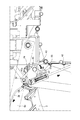
また、図1を参照して、前記副作業機(30)は、前記植付作業機(9)の前方で圃場の整地を行う整地装置(30)である。 Moreover, with reference to FIG. 1, the said sub work machine (30) is the leveling apparatus (30) which performs the leveling of the agricultural field in front of the said planting work machine (9).
なお、上述カッコ内の符号は、図面と対照するためのものであるが、何ら本発明の構成を限定するものではない。 In addition, although the code | symbol in the said parenthesis is for contrast with drawing, it does not limit the structure of this invention at all.
請求項1に係る本発明によると、副作業機への駆動力の伝達を入切するクラッチ機構を、回動部材を介して、操作レバー又は昇降リンクによって操作可能に構成している。そして、該回動部材をクラッチ切位置に保持する保持部を設けたので、植付作業機の取り外しに当たって操作レバーと回動部材との接続を解除しても、クラッチ機構を切状態に保持することができる。これにより、安価かつコンパクトな構成で、植付作業機の着脱作業時の安全性を向上することができる。また、昇降リンクを下方に下げた状態でも、保持部によってクラッチ機構を切状態に保持することができるので、作業機の着脱作業性を向上することができる。 According to the first aspect of the present invention, the clutch mechanism for turning on and off the transmission of the driving force to the sub work machine is configured to be operable by the operation lever or the lifting link via the rotating member. And since the holding | maintenance part which hold | maintains this rotation member in a clutch cut | disconnection position was provided, even if the connection of an operation lever and a rotation member is cancelled | released when removing a planting work machine, a clutch mechanism is hold | maintained in a cut-off state. be able to. Thereby, the safety | security at the time of the attachment or detachment operation | work of a planting work machine can be improved with an inexpensive and compact structure. Even in a state where the elevating link is lowered, the clutch mechanism can be held in the disengaged state by the holding portion, so that the workability of the work implement can be improved.
請求項2に係る本発明によると、植付作業機装着時に回動部材と連繋部材とを連結する回動ピンを、植付作業機取り外し時に回動部材をクラッチ切位置に位置決めするピンとして兼用したので、コストダウンすることができると共に、回動ピンの紛失を防止することができる。また、回動ピンを差し替える箇所が近いために、回動ピンの差し替え作業が容易であり、作業性を向上することができる。 According to the second aspect of the present invention, the rotation pin that connects the rotation member and the connecting member when the planting work machine is mounted is also used as a pin that positions the rotation member at the clutch disengagement position when the planting work machine is removed. As a result, the cost can be reduced and the loss of the rotating pin can be prevented. Moreover, since the place which replaces a rotation pin is near, the replacement | exchange operation | work of a rotation pin is easy and workability | operativity can be improved.
請求項3に係る本発明によると、植付作業機装着時に操作具と連繋部材とを連結する操作具ピンを、植付作業機取り外し時に回動部材をクラッチ切位置に位置決めするピンとして兼用したので、コストダウンすることができると共に、操作具ピンの紛失を防止することができる。また、操作具ピンを差し替える箇所が近いために、操作具ピンの差し替え作業が容易であり、作業性を向上することができる。 According to the third aspect of the present invention, the operation tool pin for connecting the operation tool and the connecting member when the planting work machine is mounted is also used as a pin for positioning the rotating member at the clutch disengagement position when the planting work machine is removed. Therefore, the cost can be reduced and the loss of the operation tool pin can be prevented. Further, since the places where the operation tool pins are replaced are close, the operation tool pin replacement work is easy, and workability can be improved.
請求項4に係る本発明によると、植付作業機を最上位置まで上昇させると、自動的に回動部材に設けられた貫通孔と筒部材の孔とが一致するので、回動部材をクラッチ切位置で保持する際のピンの挿入作業を容易にすることができる。 According to the fourth aspect of the present invention, when the planting work machine is raised to the uppermost position, the through hole provided in the rotating member automatically matches the hole of the cylindrical member. It is possible to facilitate the insertion of the pins when holding in the cut position.
請求項5に係る本発明によると、副作業機として、整地装置に適用できる。
The present invention according to
以下、図面に沿って、本発明の実施の形態について説明する。本発明を適用した移植機1は、図1に示すように、一対の前輪2及び後輪3に支持された走行機体5を有しており、該走行機体5の後方には、昇降リンク6及び該昇降リンク6の後端に配置されたヒッチ7を介して、植付作業機9が昇降可能に連結されている。
Hereinafter, embodiments of the present invention will be described with reference to the drawings. As shown in FIG. 1, the
上記走行機体5の前部には、バッテリ等を収容するフロントカバー10が配置されており、後輪3と走行機体5との間には、エンジンEからの駆動力を変速するミッションケースMが配置されている。また、フロントカバー10の後方には、移植機1を運転操作する運転操作部11が設けられており、該運転操作部11は、ハンドル12、座席13、主変速レバー15等を有している。
A
昇降リンク6は、図2に示すように、植付作業機9を走行機体5の後部に連結する左右のトップリンク6a,6aと左右のロアリンク6b,6bと、昇降シリンダ16と、を有している。トップリンク6aとロアリンク6bの後端は、ヒッチ7のリンクブラケット17に回転自在に支持されている。ヒッチ7は、該リンクブラケット17と、該リンクブラケット17の上部及び下部に取付けられたフック19,20と、回動軸21を中心にリンクブラケット17に回動自在に支持される左右のロックアーム22,22と、左右のロックアーム22,22をロック可能なロックレバー23と、を有している。
As shown in FIG. 2, the elevating
左右のロックアーム22,22は、回動軸21を中心に連動して回動し、コイルばね25によって、図2(a)及び図2(b)に示すロック位置に付勢されている。また、リンクブラケット17は、ロックレバー23が嵌挿可能な2つのロック孔22a,22bを有しており、ロック孔22aにロックレバー23を嵌挿することで、ロックアーム22,22をロック解除位置に位置決めし、ロック孔22bにロックレバー23を嵌挿することで、ロックアーム22,22をロック位置に位置決めする。
The left and right lock
すなわち、植付作業機9を取り外す際には、まずロックレバー23を引き操作して該ロックレバー23をロック孔22bから引き抜く。そして、ロックアーム22,22を回動させてロックレバー23をロック孔22aに嵌挿する。これにより、ロックアーム22,22によるロックが解除され、フック19,20を植付作業機9から取り外すことができる。植付作業機9を装着する際には、上述した手順とは逆の手順を行う。
That is, when removing the
植付作業機9は、図1に示すように、苗マットを搭載する苗載せ台25と、該苗載せ台25に搭載された苗を圃場に植え付ける植付装置26と、を有している。植付作業機9の縦フレーム27には、平行リンク29が取付けられており、該平行リンク29には、植付作業機9の前方で圃場の整地を行う整地装置30(副作業機)が回転自在に支持される支持フレーム31が取付けられている。また、該整地装置30には、図1に示すように、ミッションケースMから整地装置30に駆動力を伝達する副PTO軸28が接続されており、植付作業機9の駆動とは独立して駆動されている。
As shown in FIG. 1, the
上記平行リンク29の上部の回動軸32には、図3に示すように、操作レバー33(操作具)の基部と、取付けアーム36と、が一体的に取付けられており、該操作レバー33を上下に揺動操作することで、回動軸32及び取付けアーム36が回動する。平行リンク29の回動軸32が回動すると、平行リンク29及び支持フレーム31を介して、整地装置30が昇降する。これにより、整地装置30による整地深さを変更することができる。また、操作レバー33は、レバーガイド35によって、任意の位置に固定することができる。
As shown in FIG. 3, a base portion of an operation lever 33 (operation tool) and an
また、上記取付けアーム36には、操作具ピン37が嵌挿されている。該操作具ピン37には、ワイヤ(連繋部材)38が取付けられており、取付けアーム36とワイヤ38は連動するように構成されている。該操作具ピン37は、Rピン39によって抜き止めされている。すなわち、操作レバー33を揺動操作することで、整地装置30が昇降すると共に、取付けアーム36が回動し、取付けアーム36を介してワイヤ38が押し引き操作される。
An
一方、ミッションケースM内には、図4に示すように、上記副PTO軸28への駆動力の伝達を入切(断接)するクラッチ機構40が設けられており、ミッションケースMの外方には、該クラッチ機構40を入切操作するクラッチアーム41が回動自在に設けられている。クラッチアーム41は、ロッド42が連結され、該ロッド42によって、後述するように回動操作される。なお、クラッチ機構40は、副PTO軸28にエンジンEからの駆動力が伝達される入状態に付勢されている。
On the other hand, in the transmission case M, as shown in FIG. 4, a
上記ロッド42のクラッチアーム41と連結されている側とは反対側の端部には、図5に示すように、走行機体5の後端に設けられた回動軸43に回動自在に支持された三角ブラケット45(回動部材)が連結されている。また、回動軸43には、三角ブラケット45に溶着され、該三角ブラケット45と共に回動する操作アーム46が支持されている。該操作アーム46の回動軸43とは反対側の端部には、回動ピン47が嵌挿されており、該回動ピン47によって、操作アーム46と上記ワイヤ38が連結されている。なお、該回動ピン47は、不図示のRピンによって抜き止めされている。
As shown in FIG. 5, an end of the
すなわち、植付作業機9に設けられた操作レバー33を操作することで、ワイヤ38が図5(b)で示す矢印の方向に引っ張られ、操作アーム46が時計回りに回動する。そして、該操作アーム46の回動に基づいて、三角ブラケット45も時計回りに回動し、該三角ブラケット45に連結されたロッド42が上方に引っ張られる。これにより、整地装置30が上方に移動して非作業状態となると共に、クラッチ機構40を入切操作するクラッチアーム41が回動し、クラッチ機構40が入状態から切状態に操作される。なお、図3において、操作レバー33を実線で示す上方の位置において、クラッチ機構40は切状態となり(図5(b)、図4(b)の状態)、操作レバー33を二点鎖線で示す下方の位置において、クラッチ機構40は入状態となる(図5(a)、図4(a)の状態)。したがって、操作レバー33は、クラッチ機構40を入切操作可能に構成される。
That is, by operating the
また、走行機体5の後端部に取付けられたブラケット49には、筒部材50が設けられている。上記三角ブラケット45は、ロッド42の引き上げ操作によってクラッチ機構40を切状態とする図5(b)に示すクラッチ切位置において、該三角ブラケット45に形成された貫通孔45aと筒部材50を対向させる。そして、上記操作具ピン37又は上記回動ピン47をこれら貫通孔45a及び筒部材50に貫通させることで、三角ブラケット45をクラッチ切位置に保持し、クラッチ機構40を切状態に保持することができる。そして、これら操作具ピン37又は回動ピン47と筒部材50は、保持部51を構成する(図7参照)。
A
また、三角ブラケット45の一端には、機体左右方向に延びるローラ付きの当接軸52が設けられている。そして、ロアリンク6bの下面には、機体左右方向に延びるプレート53(連動部材)が取付けられている。すなわち、植付作業機9が昇降リンク6を介して上昇すると、上記プレート53が三角ブラケット45に取付けられた当接軸52に当接し、図6に示すように、該三角ブラケット45を時計回りに回動させる。これにより、三角ブラケット45が上記クラッチ切位置に位置され、クラッチ機構40を切状態にすることができる。なお、植付作業機9を最上位置まで上昇させると、三角ブラケット45の貫通孔45aと、上記筒部材50とが対向し、貫通孔45aと筒部材50との位置合わせ作業を省略することができる。これにより、三角ブラケット45をクラッチ切位置で保持する際のピンの挿入作業を容易に行うことができ、作業時間を短縮することができる。また、ワイヤ38の先端に設けられた連結プレート55には、回動ピン47が嵌挿可能な長孔55aが設けられており、操作レバー33がクラッチ機構40を入状態とする位置にあって、植付作業機9を最上位置まで上昇させたとしても、長孔55a内で回動ピン47が移動し、ワイヤ38に過度の荷重がかかって該ワイヤ38が破損することを防止している。
Further, a
本発明は、以上のような構成からなるので、作業者は、植付作業機9の取り外しに当たって、図7(a)に示すように、まず植付作業機9を最上位置まで上昇させて、三角ブラケット45をクラッチ切位置に回動させる。この際、整地装置30は、植付作業機9と共に上方に移動し、駆動力が伝達されない非作業状態となっている。この状態で、例えば回動ピン47を操作アーム46及びワイヤ38から取り外し、三角ブラケット45の貫通孔45a及び筒部材50に貫通させる。そして、不図示のRピンによって回動ピン47を抜き止めする。その後、作業者は、植付作業機9用のPTO軸及び整地装置30用の副PTO軸28等の取り外し作業を行う。
Since the present invention is configured as described above, the operator, when removing the
これによって、図7(b)に示すように、昇降リンク6を下方に移動させても、三角ブラケット45がクラッチ切位置で保持され、クラッチ機構40は切状態に保持される。このような状態で、ヒッチ7から植付作業機9の取り外し作業を行うことで、安全性を向上することができる。また、回動ピン47を差し替える箇所が近いために、回動ピン47の差し替え作業が容易であり、作業性を向上することができる。また、昇降リンク6の位置に拘らずクラッチ機構40を切状態に保持することができるので、着脱作業性を向上することができる。
Accordingly, as shown in FIG. 7B, even when the elevating
また、植付作業機9の装着時に三角ブラケット45とワイヤ38とを連結する回動ピン47を、植付作業機9の取り外し時に三角ブラケット45をクラッチ切位置に位置決めするピンとして兼用したので、コストダウンすることができると共に、回動ピンの紛失を防止することができる。なお、操作具ピン37を三角ブラケット45の位置決めのためのピンとして使用することもでき、上述した効果と同様の効果を得ることができる。
In addition, the
なお、三角ブラケット45は、走行機体5の高さ方向において略中央部に配置されており、回動ピン47又は操作具ピン37の抜き差し作業が容易に行える位置に配置されている。また、操作レバー33及び昇降リンク6のいずれの操作系によってクラッチ機構40が切状態となっても、三角ブラケット45の貫通孔45a及び筒部材50にピン(回動ピン47又は操作具ピン37)を挿入するだけでクラッチ機構40の切状態を容易に保持することができる。そのため、植付作業機9の着脱作業性を向上することができる。
The
また、本実施の形態では、副作業機として整地装置を適用したが、他の作業機を適用してもよい。 Moreover, in this Embodiment, although the leveling apparatus was applied as a sub-work machine, you may apply another work machine.
また、回動ピン又は操作具ピンを保持部の一部品として兼用したが、三角ブラケットをクラッチ切位置で保持するための専用のピンを設けてもよい。 Moreover, although the rotation pin or the operation tool pin is also used as one part of the holding portion, a dedicated pin for holding the triangular bracket at the clutch disengaged position may be provided.
また、本実施の形態では、操作レバーによって整地装置の昇降及びクラッチ機構の入切操作を連動して行ったが、クラッチ機構の入切のみ行える構成としてもよい。これにより、より安価に構成することができる。 In this embodiment, the leveling device is moved up and down and the clutch mechanism is turned on and off in conjunction with the operation lever. However, the clutch mechanism may be turned on and off. Thereby, it can comprise more cheaply.
1 移植機
5 走行機体
6 昇降リンク
9 植付作業機
30 整地装置(副作業機)
33 操作レバー(操作具)
37 操作具ピン
38 ワイヤ(連繋部材)
40 クラッチ機構
45 三角ブラケット(回動部材)
45a 貫通孔
47 回動ピン
50 筒部材
51 保持部
53 プレート(連動部材)
1 transplanting
33 Control lever (control tool)
37
40
45a Through-
Claims (5)
前記走行機体に回動自在に支持され、クラッチ切位置にあって前記クラッチ機構を切状態にする回動部材と、
前記操作具と前記回動部材とを連繋する連繋部材と、
前記昇降リンクに支持され、前記植付作業機が上昇することで前記回動部材を回動させる連動部材と、
前記回動部材を前記走行機体に対して回動不能に係止して、前記昇降リンクの昇降位置に関わらず前記回動部材を前記クラッチ切位置に保持する保持部と、を備えてなる、
ことを特徴とする移植機。 A traveling machine body, a planting work machine connected to the traveling machine body through a lifting link so as to be movable up and down, and a sub-work machine supported by the planting work machine and driven independently of the planting work machine The driving machine body is provided with a clutch mechanism that is turned on and off to transmit the driving force to the sub work machine, and the clutch mechanism is inserted into the planting work machine. In the transplanting machine provided with an operation tool capable of cutting operation , the operating tool is connected to and removed from the traveling machine body together with the planting work machine ,
A rotating member that is rotatably supported by the traveling machine body and is in a clutch disengaged position to bring the clutch mechanism into a disengaged state;
A linking member linking the operating tool and the rotating member;
An interlocking member that is supported by the elevating link and rotates the rotating member by raising the planting work machine,
A holding portion that locks the rotating member with respect to the traveling machine body so as not to rotate, and holds the rotating member at the clutch disengaged position regardless of the lift position of the lift link .
A transplanter characterized by that.
前記回動ピンを前記回動部材及び前記連繋部材から取り外し、前記回動部材及び前記筒部材に貫通させることで、前記回動部材を前記クラッチ切位置に保持してなる、
請求項1記載の移植機。 The holding portion includes a cylindrical member supported by the traveling machine body, and a rotating pin that connects the rotating member and the connecting member.
The rotating member is held at the clutch disengaged position by removing the rotating pin from the rotating member and the connecting member and passing through the rotating member and the cylindrical member.
The transplanter according to claim 1.
前記操作具ピンを前記操作具及び前記連繋部材から取り外し、前記回動部材及び前記筒部材に貫通させることで、前記回動部材を前記クラッチ切位置に保持してなる、
請求項1記載の移植機。 The holding portion includes a cylinder member supported by the traveling machine body, and an operation tool pin that connects the operation tool and the connecting member.
By removing the operation tool pin from the operation tool and the connecting member and penetrating the rotation member and the tubular member, the rotation member is held at the clutch disengaged position.
The transplanter according to claim 1.
前記植付作業機を最上位置まで上昇させると、前記連動部材によって前記回動部材が回動されて、前記貫通孔と前記筒部材とが対向してなる、
請求項2又は3に記載の移植機。 The rotating member has a through hole,
When the planting machine is raised to the uppermost position, the rotating member is rotated by the interlocking member, and the through hole and the cylindrical member are opposed to each other.
The transplanter according to claim 2 or 3.
請求項1から4のいずれか1項に記載の移植機。 The sub work machine is a leveling device for leveling a farm field in front of the planting work machine.
The transplanter according to any one of claims 1 to 4.
Priority Applications (1)
| Application Number | Priority Date | Filing Date | Title |
|---|---|---|---|
| JP2015013928A JP6471999B2 (en) | 2015-01-28 | 2015-01-28 | Transplanter |
Applications Claiming Priority (1)
| Application Number | Priority Date | Filing Date | Title |
|---|---|---|---|
| JP2015013928A JP6471999B2 (en) | 2015-01-28 | 2015-01-28 | Transplanter |
Publications (2)
| Publication Number | Publication Date |
|---|---|
| JP2016136887A JP2016136887A (en) | 2016-08-04 |
| JP6471999B2 true JP6471999B2 (en) | 2019-02-20 |
Family
ID=56558254
Family Applications (1)
| Application Number | Title | Priority Date | Filing Date |
|---|---|---|---|
| JP2015013928A Active JP6471999B2 (en) | 2015-01-28 | 2015-01-28 | Transplanter |
Country Status (1)
| Country | Link |
|---|---|
| JP (1) | JP6471999B2 (en) |
Family Cites Families (3)
| Publication number | Priority date | Publication date | Assignee | Title |
|---|---|---|---|---|
| JP2004329103A (en) * | 2003-05-07 | 2004-11-25 | Mitsubishi Agricult Mach Co Ltd | Brake for paddy farming vehicle |
| JP5191278B2 (en) * | 2008-05-23 | 2013-05-08 | 三菱農機株式会社 | Transplanter |
| JP2012050342A (en) * | 2010-08-31 | 2012-03-15 | Iseki & Co Ltd | Seedling transplanter |
-
2015
- 2015-01-28 JP JP2015013928A patent/JP6471999B2/en active Active
Also Published As
| Publication number | Publication date |
|---|---|
| JP2016136887A (en) | 2016-08-04 |
Similar Documents
| Publication | Publication Date | Title |
|---|---|---|
| JP4991171B2 (en) | Rice transplanter | |
| JP5063302B2 (en) | Transplanter | |
| JP6471999B2 (en) | Transplanter | |
| JP2008099612A (en) | Working implement | |
| JP5210703B2 (en) | Tillage work machine | |
| JP2008283941A (en) | Working machine | |
| JP6342790B2 (en) | Agricultural tractor hitch device | |
| JP2011087476A (en) | Tiller | |
| JP5078299B2 (en) | Rotary tillage device | |
| JP2012191884A (en) | Rotary tiller | |
| JP4185031B2 (en) | Rotary cover | |
| JP2003023814A (en) | Farming implement | |
| JP4545075B2 (en) | Leveling cover | |
| JP2009227136A (en) | Working machine | |
| JP5463088B2 (en) | Farm machine connection device | |
| JP4344254B2 (en) | Stopper device | |
| JP5779560B2 (en) | Work equipment mounting device | |
| JP4891175B2 (en) | Transplanter | |
| JP5069933B2 (en) | Apron flip lock device for rotary work machine | |
| JP4153419B2 (en) | Passenger rice transplanter | |
| JP5157853B2 (en) | Tractor work equipment coupling device | |
| JP3964815B2 (en) | Passenger rice transplanter | |
| JP2005087170A (en) | Adapter device and implement-coupling device of transferable agricultural machine using the same | |
| JP4914754B2 (en) | Stand device | |
| JP6448048B2 (en) | Offset mowing machine |
Legal Events
| Date | Code | Title | Description |
|---|---|---|---|
| A621 | Written request for application examination |
Free format text: JAPANESE INTERMEDIATE CODE: A621 Effective date: 20171013 |
|
| A521 | Written amendment |
Free format text: JAPANESE INTERMEDIATE CODE: A821 Effective date: 20171013 |
|
| A977 | Report on retrieval |
Free format text: JAPANESE INTERMEDIATE CODE: A971007 Effective date: 20180516 |
|
| A131 | Notification of reasons for refusal |
Free format text: JAPANESE INTERMEDIATE CODE: A131 Effective date: 20180612 |
|
| A521 | Written amendment |
Free format text: JAPANESE INTERMEDIATE CODE: A523 Effective date: 20180808 |
|
| TRDD | Decision of grant or rejection written | ||
| A01 | Written decision to grant a patent or to grant a registration (utility model) |
Free format text: JAPANESE INTERMEDIATE CODE: A01 Effective date: 20181218 |
|
| A61 | First payment of annual fees (during grant procedure) |
Free format text: JAPANESE INTERMEDIATE CODE: A61 Effective date: 20190115 |
|
| R150 | Certificate of patent or registration of utility model |
Ref document number: 6471999 Country of ref document: JP Free format text: JAPANESE INTERMEDIATE CODE: R150 |
|
| S111 | Request for change of ownership or part of ownership |
Free format text: JAPANESE INTERMEDIATE CODE: R313117 |
|
| R250 | Receipt of annual fees |
Free format text: JAPANESE INTERMEDIATE CODE: R250 |
|
| R350 | Written notification of registration of transfer |
Free format text: JAPANESE INTERMEDIATE CODE: R350 |