JP6471663B2 - Diagnostic equipment - Google Patents
Diagnostic equipment Download PDFInfo
- Publication number
- JP6471663B2 JP6471663B2 JP2015186707A JP2015186707A JP6471663B2 JP 6471663 B2 JP6471663 B2 JP 6471663B2 JP 2015186707 A JP2015186707 A JP 2015186707A JP 2015186707 A JP2015186707 A JP 2015186707A JP 6471663 B2 JP6471663 B2 JP 6471663B2
- Authority
- JP
- Japan
- Prior art keywords
- temperature
- cooling water
- abnormality
- vehicle
- valve
- Prior art date
- Legal status (The legal status is an assumption and is not a legal conclusion. Google has not performed a legal analysis and makes no representation as to the accuracy of the status listed.)
- Active
Links
Images


Landscapes
- Combined Controls Of Internal Combustion Engines (AREA)
Description
本発明は、車両に備えられる診断装置に関する。 The present invention relates to a diagnostic device provided in a vehicle.
車両には、車両の運転状態を診断するための診断装置が備えられる。車両において何らかの異常が生じていると診断された場合には、診断装置は、フロントパネルの警告灯を点灯させるなどして、異常が生じている旨を運転者に報知する。 The vehicle is provided with a diagnostic device for diagnosing the driving state of the vehicle. When it is diagnosed that some abnormality has occurred in the vehicle, the diagnostic device notifies the driver that an abnormality has occurred, for example, by turning on a warning lamp on the front panel.
診断装置によって診断される項目の一つとして、温度調整弁の異常が挙げられる。温度調整弁は、車両の内燃機関とラジエータとの間で冷却水が循環する流路、の途中に設けられる弁である。冷却水が流れる経路が温度調整弁で切り換えられることにより、冷却水の温度が調整される。このような温度調整弁において例えば開故障が生じると、ラジエータには常に冷却水が供給され、冷却水の温度が下がり過ぎてしまう。このため、診断装置は、冷却水の温度に基づいて、温度調整弁が正常に動作しているか否かを判定することができる。 One of the items diagnosed by the diagnostic device is an abnormality of the temperature adjustment valve. The temperature adjustment valve is a valve provided in the middle of a flow path through which cooling water circulates between the internal combustion engine of the vehicle and the radiator. The temperature of the cooling water is adjusted by switching the path through which the cooling water flows with the temperature adjustment valve. If, for example, an open failure occurs in such a temperature control valve, cooling water is always supplied to the radiator, and the temperature of the cooling water is too low. For this reason, the diagnostic device can determine whether or not the temperature adjustment valve is operating normally based on the temperature of the cooling water.
下記特許文献1には、温度調整弁である電気制御式のサーモスタット弁、の診断を行う故障診断装置が記載されている。当該故障診断装置が搭載された車両においては、ラジエータに循環させる冷却水の温度を目標温度に一致させるように、サーモスタット弁の開閉動作が制御される。このような制御が行われている際において、目標温度と実冷却水温度との偏差が所定値よりも大きい状態となったときには、サーモスタット弁に異常が生じたとの判定がなされる。 Patent Document 1 listed below describes a failure diagnosis device that diagnoses an electrically controlled thermostat valve that is a temperature adjustment valve. In a vehicle equipped with the failure diagnosis apparatus, the opening / closing operation of the thermostat valve is controlled so that the temperature of the cooling water circulated through the radiator matches the target temperature. When such control is performed, when the deviation between the target temperature and the actual cooling water temperature is greater than a predetermined value, it is determined that an abnormality has occurred in the thermostat valve.
温度調整弁の異常が生じても、これにより直ちに冷却水の温度が変化するのではなく、異常が生じてから時間が経過した後に冷却水の温度が変化する。このため、上記特許文献1に記載されている故障診断装置では、温度調整弁における異常の発生を検知するタイミングが遅くなり、運転者への報知が遅れてしまう可能性がある。 Even if an abnormality occurs in the temperature adjustment valve, the temperature of the cooling water does not change immediately by this, but the temperature of the cooling water changes after a lapse of time since the occurrence of the abnormality. For this reason, in the failure diagnosis apparatus described in Patent Document 1, the timing for detecting the occurrence of an abnormality in the temperature adjustment valve is delayed, and there is a possibility that notification to the driver is delayed.
また、温度調整弁に異常が生じている状態には、例えば温度調整弁の弁体が動作し得なくなっている状態もあれば、弁体に亀裂が生じる等により冷却水がラジエータ側に漏れてしまっている状態もある。つまり、温度調整弁には様々な原因による異常が生じ得る。しかしながら、上記特許文献1に記載されている故障診断装置では、温度調整弁に異常が生じたか否かは判定することができるのであるが、具体的な異常の種類についてまで判定することはできない。 In addition, for example, the temperature control valve may be in a state where the valve body of the temperature control valve cannot operate, or the coolant may leak to the radiator due to a crack in the valve body. There is also a state of being trapped. That is, the temperature control valve can be abnormal due to various causes. However, in the failure diagnosis apparatus described in Patent Document 1, it is possible to determine whether or not an abnormality has occurred in the temperature adjustment valve, but it is not possible to determine a specific type of abnormality.
本発明はこのような課題に鑑みてなされたものであり、その目的は、温度調整弁に異常が生じたことを短時間のうちに検知することができ、更に好ましくは、当該異常の種類を判定することのできる診断装置を提供することにある。
The present invention has been made in view of such a problem, and an object of the present invention is to detect in a short time that an abnormality has occurred in the temperature control valve, and more preferably , to determine the type of the abnormality. An object of the present invention is to provide a diagnostic apparatus that can make a determination.
上記課題を解決するために、本発明に係る診断装置は、車両に備えられる診断装置であって、車両の内燃機関から排出される冷却水の温度を取得する水温取得部と、冷却水の温度を調整するものとして車両に設けられている温度調整弁、の異常を判定する異常判定部と、を備える。温度調整弁は、電力の供給を受けて内部の弁体を動作させ、その開度を変化させるように構成されており、且つ、車両の運転が行われる際には、弁体の位置を目標位置に一致させ、これにより冷却水の温度を目標温度に一致させる制御が行われるものである。異常判定部が、弁体の位置と目標位置との差である位置偏差と、冷却水の温度と目標温度との差である水温偏差と、に基づいて、温度調整弁の異常を判定する。異常判定部が、位置偏差又はその積算値、の絶対値が所定の位置閾値を超えると、温度調整弁に異常が生じたと判定し、車両に備えられた蓄電池(BT)の電圧が大きくなるほど、位置閾値を小さくなるように変更する。
In order to solve the above-described problem, a diagnostic device according to the present invention is a diagnostic device provided in a vehicle, and includes a water temperature acquisition unit that acquires a temperature of cooling water discharged from an internal combustion engine of the vehicle, and a temperature of the cooling water. An abnormality determination unit that determines an abnormality of a temperature adjustment valve provided in the vehicle as a device for adjusting the temperature. The temperature control valve is configured to operate the internal valve body by receiving power supply and to change the opening thereof, and when the vehicle is operated, the position of the valve body is targeted. The control is performed so that the temperature of the coolant matches the target temperature. The abnormality determination unit determines abnormality of the temperature adjustment valve based on a position deviation that is a difference between the position of the valve body and the target position and a water temperature deviation that is a difference between the temperature of the cooling water and the target temperature. When the absolute value of the position deviation or the integrated value thereof exceeds a predetermined position threshold, the abnormality determination unit determines that an abnormality has occurred in the temperature adjustment valve, and as the voltage of the storage battery (BT) provided in the vehicle increases, Change the position threshold to be smaller.
このような診断装置では、冷却水の温度と目標温度との差である水温偏差のみならず、弁体の位置と目標位置との差である位置偏差にも基づいて温度調整弁の異常が判定される。温度調整弁の異常による位置偏差への影響は、水温偏差への影響に比べて短時間のうちに現れる。このため、上記診断装置によれば、温度調整弁に異常が生じたことを短時間のうちに検知することができる。 In such a diagnostic device, abnormality of the temperature adjustment valve is determined not only based on the water temperature deviation which is the difference between the cooling water temperature and the target temperature, but also based on the position deviation which is the difference between the position of the valve body and the target position. Is done. The influence on the position deviation due to the abnormality of the temperature adjustment valve appears in a shorter time than the influence on the water temperature deviation. For this reason, according to the said diagnostic apparatus, it can detect in a short time that abnormality had arisen in the temperature control valve.
また、例えば、水温偏差が大きく位置偏差が小さい場合には、弁体は正常に動作しているにもかかわらず、冷却水がラジエータ側に漏れていることが推測される。このため、このような場合には、温度調整弁の異常の原因が、弁体の動作不良ではなく、弁体や弁体の亀裂等であると特定することができる。 For example, when the water temperature deviation is large and the position deviation is small, it is estimated that the cooling water is leaking to the radiator side even though the valve element is operating normally. For this reason, in such a case, it can be specified that the cause of the abnormality of the temperature adjustment valve is not a malfunction of the valve body but a crack of the valve body or the valve body.
尚、上記説明における弁体の「位置」には、弁体が並進運動する場合における弁体の位置のほか、弁体が回転運動する場合における回転角度も含まれる。つまり、弁体の位置とは、温度調整弁の開度を変化させるように弁体が動作する場合における、その動作量を示すものともいうことができる。 The “position” of the valve body in the above description includes not only the position of the valve body when the valve body moves in translation but also the rotation angle when the valve body rotates. That is, the position of the valve body can also be said to indicate the amount of operation when the valve body operates so as to change the opening degree of the temperature adjustment valve.
本発明によれば、温度調整弁に異常が生じたことを短時間のうちに検知することができ、更に好ましくは、当該異常の種類を判定することのできる診断装置が提供される。 According to the present invention, it is possible to detect in a short time that an abnormality has occurred in the temperature control valve, and it is more preferable to provide a diagnostic apparatus that can determine the type of the abnormality.
以下、添付図面を参照しながら本発明の実施形態について説明する。説明の理解を容易にするため、各図面において同一の構成要素に対しては可能な限り同一の符号を付して、重複する説明は省略する。 Hereinafter, embodiments of the present invention will be described with reference to the accompanying drawings. In order to facilitate the understanding of the description, the same constituent elements in the drawings will be denoted by the same reference numerals as much as possible, and redundant description will be omitted.
本実施形態に係る診断装置100は、車両10の運転状態を診断するための装置である。先ず、図1を参照しながら車両10の構成について説明する。車両10は、内燃機関20とモーターMとを備えた所謂ハイブリッド車両として構成されている。
The
内燃機関20は、ガソリンを燃料として駆動される4サイクルレシプロエンジンである。内燃機関20は、シリンダヘッド21とシリンダブロック22とを有している。これらの内部には不図示の気筒が複数形成されている。各気筒において吸気行程、圧縮行程、燃焼行程、排気行程の各行程が繰り返し行われ、これにより車両10の走行に必要な駆動力が生じる。
The
モーターMは三相交流モーターである。車両10には、バッテリーと電力変換器が搭載されている(いずれも不図示)。バッテリーから出力された直流電力は、電力変換器によって三相交流電力に変換され、モーターMに供給される。モーターMに三相交流電力が供給されると、車両10の走行に必要な駆動力が生じる。当該駆動力の大きさは、電力変換器のスイッチング動作によって調整される。
Motor M is a three-phase AC motor. The
車両10は、内燃機関20の駆動力、及びモーターMの駆動力の両方により走行することができる。また、内燃機関20の駆動力のみによって走行したり、モーターMの駆動力のみによって走行したりすることもできる。
The
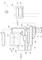
車両10は、以上に説明した内燃機関20やモーターMのほか、冷却装置50と、電圧センサ60と、外気温センサ70と、報知装置80と、制御装置40と、を備えている。
In addition to the
冷却装置50は、運転中において多量の熱を発生させる内燃機関20を冷却し、適温に維持するための装置である。冷却装置50は、循環流路510と、ウォーターポンプ520と、ラジエータ530と、第1バイパス流路540と、第2バイパス流路541と、温度調整弁560と、を有している。
The
循環流路510は、内燃機関20と、後述のラジエータ530との間で冷却水を循環させるための流路である。以下では、循環流路510のうち、冷却水が内燃機関20からラジエータ530に向かって流れる流路を「第1流路511」とも表記する。また、循環流路510のうち、冷却水がラジエータ530から内燃機関20に向かって流れる流路を「第2流路512」とも表記する。
内燃機関20の内部には、内部流路210が形成されている。第2流路512を通って内燃機関20に供給された冷却水は、内部流路210を通りながら内燃機関20から熱を奪う。これにより高温となった冷却水は、内部流路210から第1流路511へと排出される。
An
第1流路511のうち内燃機関20寄りとなる位置には、内燃機関20から排出された直後における冷却水の温度を測定するための水温センサ570が設けられている。水温センサ570で測定された水温に基づく信号は、診断装置100及び制御装置40に入力されている。
A
ウォーターポンプ520は、冷却水が循環流路510を循環するように、冷却水を圧送する電動ポンプである。ウォーターポンプ520は、第2流路512のうち内燃機関20寄りとなる位置に配置されている。ウォーターポンプ520の動作は、後述の制御装置40によって制御される。また、診断装置100が、制御装置40を介してウォーターポンプ520の動作を制御することも可能となっている。
The
ウォーターポンプ520は、その回転数を示す信号を外部に出力する。当該信号は制御装置40に入力される。制御装置40は、ウォーターポンプ520からの信号を参照しながら、ウォーターポンプ520の動作を制御する。
ラジエータ530は、循環流路510を流れる冷却水と、車両10の外部から導入された空気とを熱交換させることにより、冷却水の温度を低下させる熱交換器である。ラジエータ530の近傍にはラジエータファン531が設けられている。ラジエータファン531は、ラジエータ530における熱交換が効率的に行われるよう、ラジエータ530に空気を送り込むためのものである。
The
第1バイパス流路540は、第1流路511と第2流路512とを繋ぐように形成された流路である。後述の温度調整弁560の動作によって、冷却水がラジエータ530を通ることなく、第1バイパス流路540のみを流れる状態とすることができる。また、ラジエータ530及び第1バイパス流路540の両方を冷却水が流れる状態とすることもできる。
The
第1バイパス流路540の途中には、ヒータコア551が設けられている。ヒータコア551は、後述のブロア552と共に、車両10に備えられた暖房装置550の一部を構成するものである。ヒータコア551は、内部を流れる高温の冷却水と、ヒータコア551を通過する空気とを熱交換させることにより、当該空気の温度を上昇させる熱交換器である。ヒータコア551の近傍にはブロア552が設けられている。ブロア552は、ヒータコア551における熱交換が効率的に行われるよう、ヒータコア551に空気を送り込むためのものである。ヒータコア551を通過してその温度を上昇させた空気は、不図示のダクトを通って車両10の車室内に供給される。
A
冷却水は、ヒータコア551を通過する際、空気との熱交換によってその温度を低下させる。ヒータコア551を通過する際において冷却水が失う熱量は、ヒータコア551を含む暖房装置550の動作状態によって変化する。
When the cooling water passes through the
第2バイパス流路541は、上記の第1バイパス流路540と同様に、第1流路511と第2流路512とを繋ぐように形成された流路である。温度調整弁560の動作によって、冷却水がラジエータ530を通ることなく、第1バイパス流路540及び第2バイパス流路541を流れる状態とすることができる。また、ラジエータ530、第1バイパス流路540、及び第2バイパス流路541の全てを冷却水が流れる状態とすることもできる。
The
第2バイパス流路541の途中には、オイルクーラ590が設けられている。オイルクーラ590は、内燃機関20に供給されるオイルを冷却するための熱交換器である。冷却水は、オイルクーラ590を通過する際、オイルとの熱交換によってその温度を上昇させる。
An
温度調整弁560は、第1流路511と第1バイパス流路540とが分岐する部分に設けられている。当該部分は、第1流路511と第2バイパス流路541とが分岐する部分でもある。
The
温度調整弁560は、電力の供給を受けて内部の弁体561を回転させることにより、流路を切り換えることのできる電動式の弁である。温度調整弁560の動作、具体的には弁体561の回転角度の変化は、制御装置40によって制御される。
The
弁体561が回転することにより、第1流路511から第1バイパス流路540のみに冷却水が供給される状態(以下、「第1状態」とも称する)とすることができる。また、第1流路511から第1バイパス流路540及び第2バイパス流路に冷却水が供給され、ラジエータ530には冷却水が供給されない状態(以下、「第2状態」とも称する)とすることもできる。更に、第1流路511から第1バイパス流路540、第2バイパス流路、及びラジエータ530のいずれにも冷却水が供給される状態(以下、「第3状態」とも称する)とすることもできる。
By rotating the
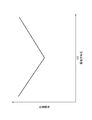
図2に示されるのは、温度調整弁560の動作特性を示すグラフである。グラフの横軸は、温度調整弁560の内部における弁体561の回転角度である。グラフの縦軸は開口率、すなわち温度調整弁560の開度である。線G10で示されるのは、温度調整弁560からヒータコア551に向かう流路の開度の変化である。線G20で示されるのは、温度調整弁560からオイルクーラ590に向かう流路の開度の変化である。線G30で示されるのは、温度調整弁560からラジエータ530に向かう流路の開度の変化である。
FIG. 2 is a graph showing the operating characteristics of the
電動式の弁である温度調整弁560は、制御装置40からの制御信号に基づいてその弁体561を回転させる。弁体561の回転角度がd0からd10までの範囲であるときには、ヒータコア551に向かう流路、オイルクーラ590に向かう流路、及びラジエータ530に向かう流路のいずれもが全閉となっている。
The
弁体561の回転角度がd10よりも大きくなると、回転角度の変化に伴ってヒータコア551に向かう流路の開度のみが大きくなって行く。弁体561の回転角度がd20になると、ヒータコア551に向かう流路のみが全開となる。オイルクーラ590に向かう流路、及びラジエータ530に向かう流路はいずれも全閉のままである。
When the rotation angle of the
その後、弁体561の回転角度がd30よりも大きくなると、回転角度の変化に伴ってオイルクーラ590に向かう流路の開度が大きくなって行く。このとき、ヒータコア551に向かう流路は全開のままである。また、ラジエータ530に向かう流路は全閉のままである。弁体561の回転角度がd40になると、ヒータコア551に向かう流路、及びオイルクーラ590に向かう流路、の両方が全開となる。ラジエータ530に向かう流路は全閉のままである。
Thereafter, when the rotation angle of the
その後、弁体561の回転角度がd50よりも大きくなると、回転角度の変化に伴ってラジエータ530に向かう流路の開度が大きくなって行く。このとき、ヒータコア551に向かう流路、及びオイルクーラ590に向かう流路はいずれも全開のままである。弁体561の回転角度がd60になると、ヒータコア551に向かう流路、オイルクーラ590に向かう流路、及びラジエータ530に向かう流路のいずれもが全開となる。
Thereafter, when the rotation angle of the
弁体561の回転角度がd10とd30との間となっている状態が、先述の第1状態に該当する。弁体561の回転角度がd30とd50との間となっている状態が、先述の第2状態に該当する。弁体561の回転角度がd50とd60との間となっている状態が、先述の第3状態に該当する。
The state in which the rotation angle of the
ところで、このような電動式の弁である温度調整弁560は、本実施形態のように弁体561が回転運動することによって開度が変化するものであってもよいが、弁体561が並進運動することによって開度が変化するものであってもよい。つまり、弁体561が動作してその位置を変化させることにより、温度調整弁560の開度が変化するような構成であればよい。
By the way, the
以下の説明においては、図2の横軸に示される弁体561の回転角度のことを「弁体位置」とも表記することとする。弁体位置は、温度調整弁560の開度を変化させるように弁体561が動作する場合における、その動作量を示すものということができる。弁体位置には、本実施形態のように弁体561が回転運動する場合における回転角度のほか、弁体561が並進運動する場合における弁体561の位置も含まれる。
In the following description, the rotation angle of the
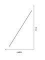
温度調整弁560は、現時点における弁体561の回転角度、すなわち弁体位置に対応する電圧を外部に出力する機能を有している。図3に示されるのは、温度調整弁560からの出力電圧と弁体位置との関係を示すグラフである。本実施形態では、出力電圧と弁体位置とは概ね比例する。弁体位置がd0のとき(図2を参照)には、出力電圧は値V10となっている。弁体位置がd60のとき(図2を参照)には、出力電圧は値V10よりも大きな値V20となっている。
The
温度調整弁560からの出力電圧は、制御装置40、及び診断装置100の両方に入力されている。制御装置40は、この出力電圧によって現時点における弁体位置を把握しながら、弁体位置を目標位置に一致させる制御を行う。
The output voltage from the
図1に戻って説明を続ける。電圧センサ60は、車両10に搭載された蓄電池BTの端子間電圧(以下、「蓄電池電圧」とも表記する)を測定するためのセンサである。蓄電池BTは、車両10に搭載された電力消費機器に電力を供給するものである。電力消費機器には、温度調整弁560も含まれる。測定された蓄電池電圧に基づく信号は、診断装置100に入力されている。
Returning to FIG. The
外気温センサ70は、車両10の外部の気温、すなわち外気温を測定するためのセンサである。測定された外気温に基づく信号は、診断装置100に入力されている。
The outside
報知装置80は、診断装置100により行われた車両10の診断結果を運転者に報知するための装置である。車両10において何らかの異常が生じていることが診断装置100により診断されると、報知装置80は、フロントパネルに設けられた警告灯を点灯させることによって運転者への報知を行う。
The
制御装置40は、車両10の全体の動作を制御するECUである。制御装置40は、CPU、ROM、RAM等を備えたコンピュータシステムとして構成されている。制御装置40は、既に述べたようにウォーターポンプ520の動作や温度調整弁560等の動作を制御する。
The
車両10の運転が行われている際には、制御装置40は、水温センサ570で測定される冷却水の温度を目標温度に一致させる制御を行う。例えば、冷却水の温度が目標温度よりも高いときには、ラジエータ530に供給される冷却水の流量を増加させるよう、弁体561の目標位置を開弁側(つまり図2における右側)に変化させる。
When the operation of the
また、冷却水の温度が目標温度よりも低いときには、ラジエータ530に供給される冷却水の流量を減少させるよう、弁体561の目標位置を閉弁側(つまり図2における左側)に変化させる。
When the temperature of the cooling water is lower than the target temperature, the target position of the
また、内燃機関20が始動された直後には、制御装置40が第1状態又は第2状態への切り替えを行うことにより、温度調整弁560からラジエータ530に向かう流路を閉塞させる。これにより、内燃機関20の暖機が促進される。
Further, immediately after the
以下では、実際の弁体位置と目標位置との差のことを「位置偏差」とも称する。また、冷却水の実際の温度と目標温度との差のことを「水温偏差」とも称する。制御装置40により、位置偏差及び水温偏差の両方を0に近づけるような制御が行われる。
Hereinafter, the difference between the actual valve position and the target position is also referred to as “positional deviation”. Further, the difference between the actual temperature of the cooling water and the target temperature is also referred to as “water temperature deviation”. The
制御装置40は、車両10の運転状況に応じて目標温度を変化させる。例えば、車両10の走行負荷が大きくなったときには、ノッキングの発生を抑制するために、目標温度を低くなるように変更する。
The
このように、目標温度は常に一定なのではなく、そのときの車両10の運転状況に応じて変更される。換言すれば、冷却水の温度を運転状況に応じて適宜変更することができるように、電動式の弁である温度調整弁560が用いられている。
Thus, the target temperature is not always constant, but is changed according to the driving situation of the
診断装置100は、先に説明した制御装置40と同様に、CPU、ROM、RAM等を備えたコンピュータシステムとして構成されている。診断装置100は、車両10の全体の制御を行う制御装置40とは別の装置として構成されていてもよいのであるが、制御装置40と一体の装置として構成されていてもよい。つまり、以下に説明する診断装置100の機能の一部又は全てが、制御装置40に備えられていてもよい。
The
診断装置100は、機能的な制御ブロックとして、水温取得部110と、異常判定部120と、を備えている。
The
水温取得部110は、水温センサ570から受信される信号に基づいて、内燃機関20から排出される冷却水の温度を算出し取得する部分である。
The water
異常判定部120は、温度調整弁560に異常が生じたか否かを判定する部分である。例えば、冷却水の温度が低い状態が長時間に亘り継続されている場合には、温度調整弁560が開状態のまま弁体561が動かなくなってしまっている可能性がある。また、弁体561に亀裂が生じる等により、冷却水がラジエータ側に漏れてしまっているという可能性もある。つまり、ラジエータ530に冷却水が向かう流路が完全には閉塞されないため、冷却水がラジエータ530を通って冷却され続けていると推測される。
The
異常判定部120は、位置偏差と水温偏差との両方に基づいて、温度調整弁560に異常が生じたか否かを判定する。以下では、その具体的な判定方法について説明する。
The
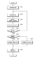
位置偏差が正常であるか否かを判定するために異常判定部120で実行される処理について、図4を参照しながら説明する。図4に示される一連の処理は、後に説明する図9の処理から呼び出されるサブルーチンとして、所定の周期が経過する毎に繰り返し実行される。
A process executed by the
最初のステップS01では、位置閾値が取得される。位置閾値とは、位置偏差が正常か否かを判定するために用いられる閾値である。後に説明するように、位置偏差の積算値の絶対値が位置閾値を超えた場合には、位置偏差が異常であると判定される。 In the first step S01, a position threshold value is acquired. The position threshold value is a threshold value used for determining whether or not the position deviation is normal. As will be described later, when the absolute value of the integrated value of the position deviation exceeds the position threshold value, it is determined that the position deviation is abnormal.
ところで、蓄電池電圧が小さいとき、すなわち、温度調整弁560に供給される電圧が小さいときには、温度調整弁560における弁体561の動作が緩慢になる傾向がある。その結果、温度調整弁560には何ら異常が生じていないにも拘らず、一時的に位置偏差が大きくなってしまい、位置偏差が異常であると判定されてしまう可能性がある。
By the way, when the storage battery voltage is small, that is, when the voltage supplied to the
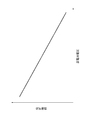
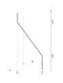
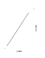
そこで、本実施形態では、そのときの蓄電池電圧に応じて位置閾値が適宜変更される。図5には、蓄電池電圧と、これに応じて設定される位置閾値との関係が示されている。図5に示されるように、蓄電池電圧が大きくなるほど、位置閾値は小さな値に変更される。換言すれば、蓄電池電圧が小さくなるほど、位置閾値は大きな値に変更される。 Therefore, in the present embodiment, the position threshold is appropriately changed according to the storage battery voltage at that time. FIG. 5 shows the relationship between the storage battery voltage and the position threshold value set accordingly. As FIG. 5 shows, a position threshold value is changed into a small value, so that a storage battery voltage becomes large. In other words, the position threshold value is changed to a larger value as the storage battery voltage decreases.
このため、蓄電池電圧が低下して弁体561の動作が緩慢になっても、位置偏差が異常であると判定されてしまうようなことが防止される。図5に示される蓄電池電圧と位置閾値との関係は、予めマップとして作成され、診断装置100のROMに記憶されている。異常判定部120は、当該マップを参照することにより、蓄電池電圧に対応する位置閾値を取得する。
For this reason, even if the storage battery voltage decreases and the operation of the
図4に戻って説明を続ける。ステップS01に続くステップS02では、現在の位置偏差が算出される。具体的には、温度調整弁560からの出力電圧に基づいて弁体位置が取得され、当該弁体位置から目標位置を差し引くことによって現在の位置偏差が算出される。
Returning to FIG. 4, the description will be continued. In step S02 following step S01, the current position deviation is calculated. Specifically, the valve position is acquired based on the output voltage from the
ステップS02に続くステップS03では、ステップS02で算出された位置偏差が積算値に加えられる。この積算値は、初期値が0の変数であって、ステップS03の処理が行われる毎に位置偏差が加えられていく変数となっている。 In step S03 following step S02, the position deviation calculated in step S02 is added to the integrated value. This integrated value is a variable whose initial value is 0, and is a variable to which a positional deviation is added each time the process of step S03 is performed.
ステップS03に続くステップS04では、カウンタに1が加えられる。このカウンタは、初期値が0の変数であって、ステップS04の処理が行われる毎に1が加えられていく変数となっている。カウンタは、ステップS02及びステップS03の処理が所定回数だけ繰り返し実行されるように、これらの実行回数をカウントするための変数である。 In step S04 following step S03, 1 is added to the counter. This counter is a variable with an initial value of 0, and is a variable that is incremented by 1 each time the process of step S04 is performed. The counter is a variable for counting the number of executions so that the processes of step S02 and step S03 are repeatedly executed a predetermined number of times.
ステップS04に続くステップS05では、カウンタの値が最大値に到達したか否かが判定される。ここでいう最大値とは、上記の「所定回数」のことである。カウンタの値が最大値に到達していれば、ステップS06に移行する。カウンタの値が未だ最大値に到達していなければ、ステップS02以降の処理が再度実行される。 In step S05 following step S04, it is determined whether or not the value of the counter has reached the maximum value. The maximum value here is the “predetermined number of times” described above. If the counter value has reached the maximum value, the process proceeds to step S06. If the value of the counter has not yet reached the maximum value, the processes after step S02 are executed again.
ステップS06では、ステップS03で算出された積算値の絶対値が、ステップS01で取得された位置閾値を超えているか否かが判定される。積算値の絶対値が位置偏差を超えていれば、ステップS07に移行する。ステップS07に移行したということは、弁体位置が目標位置からずれている状態が高頻度で発生しているということである。このため、ステップS07では、位置偏差が異常であると判定される。 In step S06, it is determined whether or not the absolute value of the integrated value calculated in step S03 exceeds the position threshold acquired in step S01. If the absolute value of the integrated value exceeds the position deviation, the process proceeds to step S07. The transition to step S07 means that a state in which the valve body position deviates from the target position occurs frequently. For this reason, in step S07, it is determined that the position deviation is abnormal.
ステップS06において、積算値の絶対値が位置偏差を超えていなければ、ステップS08に移行する。ステップS08に移行したということは、弁体位置が目標位置からずれている状態の発生頻度は小さく、弁体561は概ね正常に動作しているということである。このため、ステップS08では、位置偏差が正常であると判定される。
In step S06, if the absolute value of the integrated value does not exceed the position deviation, the process proceeds to step S08. The transition to step S08 means that the occurrence frequency of the state in which the valve body position is deviated from the target position is small, and the
ステップS07及びステップS08に続くステップS09では、積算値とカウンタがそれぞれ0に設定される。その後、図4に示される一連の処理を終了する。 In step S09 following step S07 and step S08, the integrated value and the counter are set to 0, respectively. Thereafter, the series of processes shown in FIG.
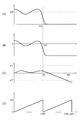
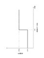
異常判定部120による位置偏差の判定が以上のように行われる際における、弁体位置や位置偏差等の変化の一例を、図6を参照しながら説明する。図6(A)に示されるのは、実際の弁体位置の変化である。また、図6(B)に示されるのは位置偏差の変化である。この例では、弁体位置を一定の目標位置SPに一致させる制御が行われている。ただし時刻t10において温度調整弁560に故障が生じ、以降は弁体位置が目標位置SPから乖離してしまっている。つまり、時刻t10以降においては位置偏差の絶対値が大きくなってしまっている。
An example of changes in valve position, position deviation, etc. when the position determination by the
図6(C)に示されるのは、図4のステップS06で算出される積算値の変化である。温度調整弁560に故障が生じる時刻t10よりも前においては、積算値の絶対値は位置閾値PTよりも小さくなっている。しかしながら、時刻t10以降においては、積算値の絶対値は次第に大きくなって行き、時刻t150において位置閾値PTを超えてしまっている。
FIG. 6C shows a change in the integrated value calculated in step S06 in FIG. Prior to time t10 when the
図6(D)に示されるのは、図4のステップS04で算出されるカウンタの変化である。図6(D)の例では、時刻t100、及び時刻t200においてカウンタの値が最大値UCに到達しており、それと同時に0にリセットされている。積算値の絶対値が位置閾値を超えたか否かの判定(つまり、ステップS06の処理)は、カウンタの値が最大値に到達したタイミングで行われる。 FIG. 6D shows the change in the counter calculated in step S04 in FIG. In the example of FIG. 6D, the value of the counter reaches the maximum value UC at time t100 and time t200, and is reset to 0 at the same time. The determination as to whether or not the absolute value of the integrated value has exceeded the position threshold (that is, the process of step S06) is performed at the timing when the counter value reaches the maximum value.
時刻t100においては、故障が生じた直後であるため、積算値の絶対値は位置閾値PTを超えていない。このため、位置偏差は正常であると判定される。これに対し、時刻t150よりも後の時刻t200においては、積算値の絶対値は位置閾値PTを超えている。このため、位置偏差は異常であると判定される。 At time t100, since it is immediately after a failure has occurred, the absolute value of the integrated value does not exceed the position threshold value PT. For this reason, it is determined that the position deviation is normal. On the other hand, at time t200 after time t150, the absolute value of the integrated value exceeds the position threshold value PT. For this reason, it is determined that the position deviation is abnormal.
尚、位置偏差が異常であるか否かの判定は、上記のように位置偏差の積算値に基づいて行われるのではなく、位置偏差の瞬時値に基づいて行われてもよい。つまり、図4のステップS06において、位置偏差の絶対値が位置閾値を超えているか否かの判定が行われることとしてもよい。 Note that the determination of whether or not the position deviation is abnormal may be made based on the instantaneous value of the position deviation, not based on the integrated value of the position deviation as described above. That is, in step S06 in FIG. 4, it may be determined whether or not the absolute value of the position deviation exceeds the position threshold value.
しかしながら、そのような態様とした場合には、位置偏差が瞬間的にのみ大きくなった際や、弁体位置を示す出力電圧にノイズが生じた際などにおいて、位置偏差が異常であるとの誤判定がなされてしまう可能性がある。このため、位置偏差が異常であるか否かの判定を安定的に行うためには、本実施形態のように、位置偏差の積算値に基づく判定を行う方が望ましい。 However, when such a mode is adopted, when the position deviation increases only momentarily or when noise occurs in the output voltage indicating the valve body position, an error that the position deviation is abnormal is detected. The determination may be made. For this reason, in order to stably determine whether or not the position deviation is abnormal, it is desirable to perform the determination based on the integrated value of the position deviation as in the present embodiment.
次に、水温偏差が正常であるか否かを判定するために異常判定部120で実行される処理について、図7を参照しながら説明する。図7に示される一連の処理は、後に説明する図9の処理から呼び出されるサブルーチンとして、所定の周期が経過する毎に繰り返し実行される。
Next, processing executed by the
最初のステップS11では、水温閾値が取得される。水温閾値とは、水温偏差が正常か否かを判定するために用いられる閾値である。後に説明するように、水温偏差の積算値の絶対値が水温閾値を超えた場合には、水温偏差が異常であると判定される。 In the first step S11, a water temperature threshold is acquired. The water temperature threshold value is a threshold value used for determining whether or not the water temperature deviation is normal. As will be described later, when the absolute value of the integrated value of the water temperature deviation exceeds the water temperature threshold, it is determined that the water temperature deviation is abnormal.
ところで、外気温が低いときには、ラジエータ530や循環流路510等における冷却水の放熱が生じやすいため、冷却水の温度が比較的不安定となる傾向がある。その結果、温度調整弁560には何ら異常が生じていないにも拘らず、一時的に水温偏差が大きくなってしまい、水温偏差が異常であると判定されてしまう可能性がある。
By the way, when the outside air temperature is low, the heat of the cooling water tends to be radiated in the
そこで、本実施形態では、外気温センサ70で測定された外気温に応じて水温閾値が適宜変更される。図8には、外気温と、これに応じて設定される水温閾値との関係が示されている。図8に示されるように、外気温が高くなるほど、水温閾値は小さな値に変更される。換言すれば、外気温が低くなるほど、水温閾値は大きな値に変更される。
Therefore, in the present embodiment, the water temperature threshold is appropriately changed according to the outside air temperature measured by the outside
このため、外気温が低下して冷却水の温度が不安定になっても、水温偏差が異常であると判定されてしまうようなことが防止される。図8に示される外気温と水温閾値との関係は、予めマップとして作成され、診断装置100のROMに記憶されている。異常判定部120は、当該マップを参照することにより、外気温に対応する水温置閾値を取得する。
For this reason, even if the outside air temperature decreases and the temperature of the cooling water becomes unstable, it is prevented that the water temperature deviation is determined to be abnormal. The relationship between the outside air temperature and the water temperature threshold shown in FIG. 8 is created in advance as a map and stored in the ROM of the
図7に戻って説明を続ける。ステップS11に続くステップS12では、現在の水温偏差が算出される。具体的には、水温センサ570からの信号に基づいて冷却水の温度が取得され、当該温度から目標温度を差し引くことによって現在の水温偏差が算出される。
Returning to FIG. 7, the description will be continued. In step S12 following step S11, the current water temperature deviation is calculated. Specifically, the temperature of the cooling water is acquired based on a signal from the
ステップS12に続くステップS13では、ステップS12で算出された水温偏差が積算値に加えられる。この積算値は、初期値が0の変数であって、ステップS13の処理が行われる毎に水温偏差が加えられていく変数となっている。 In step S13 following step S12, the water temperature deviation calculated in step S12 is added to the integrated value. This integrated value is a variable whose initial value is 0, and is a variable to which a water temperature deviation is added each time the process of step S13 is performed.
ステップS13に続くステップS14では、カウンタに1が加えられる。このカウンタは、初期値が0の変数であって、ステップS14の処理が行われる毎に1が加えられていく変数となっている。カウンタは、ステップS12及びステップS13の処理が所定回数だけ繰り返し実行されるように、これらの実行回数をカウントするための変数である。 In step S14 following step S13, 1 is added to the counter. This counter is a variable with an initial value of 0, and is a variable that is incremented by 1 each time the process of step S14 is performed. The counter is a variable for counting the number of executions so that the processes of step S12 and step S13 are repeatedly executed a predetermined number of times.
ステップS14に続くステップS15では、カウンタの値が最大値に到達したか否かが判定される。ここでいう最大値とは、上記の「所定回数」のことである。カウンタの値が最大値に到達していれば、ステップS16に移行する。カウンタの値が未だ最大値に到達していなければ、ステップS12以降の処理が再度実行される。 In step S15 following step S14, it is determined whether or not the value of the counter has reached the maximum value. The maximum value here is the “predetermined number of times” described above. If the counter value reaches the maximum value, the process proceeds to step S16. If the value of the counter has not yet reached the maximum value, the processes after step S12 are executed again.
ステップS16では、ステップS13で算出された積算値の絶対値が、ステップS11で取得された水温閾値を超えているか否かが判定される。積算値の絶対値が水温偏差を超えていれば、ステップS17に移行する。ステップS17に移行したということは、冷却水の温度が目標温度からずれている状態が高頻度で発生しているということである。このため、ステップS17では、水温偏差が異常であると判定される。 In step S16, it is determined whether or not the absolute value of the integrated value calculated in step S13 exceeds the water temperature threshold acquired in step S11. If the absolute value of the integrated value exceeds the water temperature deviation, the process proceeds to step S17. The transition to step S17 means that a state in which the temperature of the cooling water deviates from the target temperature occurs frequently. For this reason, in step S17, it is determined that the water temperature deviation is abnormal.
ステップS16において、積算値の絶対値が水温偏差を超えていなければ、ステップS18に移行する。ステップS18に移行したということは、冷却水の温度が目標温度からずれている状態の発生頻度は小さく、弁体561は概ね正常に動作しているということである。このため、ステップS18では、水温偏差が正常であると判定される。
If the absolute value of the integrated value does not exceed the water temperature deviation in step S16, the process proceeds to step S18. The transition to step S18 means that the occurrence frequency of the state in which the temperature of the cooling water is deviated from the target temperature is small, and the
ステップS17及びステップS18に続くステップS19では、積算値とカウンタがそれぞれ0に設定される。その後、図7に示される一連の処理を終了する。 In step S19 following step S17 and step S18, the integrated value and the counter are each set to 0. Thereafter, the series of processing shown in FIG.
尚、水温偏差が異常であるか否かの判定は、上記のように水温偏差の積算値に基づいて行われるのではなく、水温偏差の瞬時値に基づいて行われてもよい。つまり、図7のステップS16において、水温偏差の絶対値が水温閾値を超えているか否かの判定が行われることとしてもよい。 Note that the determination of whether or not the water temperature deviation is abnormal may be made based on the instantaneous value of the water temperature deviation instead of being based on the integrated value of the water temperature deviation as described above. That is, in step S16 of FIG. 7, it may be determined whether or not the absolute value of the water temperature deviation exceeds the water temperature threshold.
しかしながら、そのような態様とした場合には、水温偏差が瞬間的にのみ大きくなった際や、水温センサ570からの信号にノイズが生じた際などにおいて、水温偏差が異常であるとの誤判定がなされてしまう可能性がある。このため、水温偏差が異常であるか否かの判定を安定的に行うためには、本実施形態のように、水温偏差の積算値に基づく判定を行う方が望ましい。
However, in such a case, when the water temperature deviation increases only momentarily or when noise occurs in the signal from the
異常判定部120による位置偏差の判定が以上のように行われる際における、冷却水の温度や水温偏差、及びその積算値等の変化は、図6に示される位置偏差等の変化と同様である。このため、図示及び具体的な説明は省略する。
Changes in the temperature of the cooling water, the water temperature deviation, and the integrated value thereof when the position determination by the
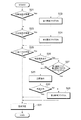
温度調整弁560に異常が生じたか否かを判定するために、診断装置100の異常判定部120で行われる処理について、図9を参照しながら説明する。図9に示される一連の処理は、所定の周期が経過する毎に繰り返し実行される。
A process performed by the
最初のステップS21では、既に説明した図4の処理が実行されることにより、位置偏差が異常であるか否かが判定される。位置偏差が正常である場合にはステップS23に移行する。位置偏差が異常である場合にはステップS22に移行する。ステップS22では、第1異常フラグがONに設定される。第1異常フラグとは、診断装置100のRAMに記憶される変数であって、ONまたはOFFのいずれのかの値が設定されるものである。図9の処理が開始される前における第1異常フラグの初期値はOFFとなっている。ステップS22で第1異常フラグがONに設定されると、ステップS23に移行する。
In the first step S21, it is determined whether or not the position deviation is abnormal by executing the process of FIG. 4 already described. If the position deviation is normal, the process proceeds to step S23. If the position deviation is abnormal, the process proceeds to step S22. In step S22, the first abnormality flag is set to ON. The first abnormality flag is a variable stored in the RAM of the
ステップS23では、既に説明した図7の処理が実行されることにより、水温偏差が異常であるか否かが判定される。水温偏差が正常である場合にはステップS25に移行する。水温偏差が異常である場合にはステップS24に移行する。ステップS24では、第2異常フラグがONに設定される。第2異常フラグとは、診断装置100のRAMに記憶される変数であって、ONまたはOFFのいずれのかの値が設定されるものである。図9の処理が開始される前における第2異常フラグの初期値はOFFとなっている。ステップS24で第2異常フラグがONに設定されると、ステップS25に移行する。
In step S23, it is determined whether or not the water temperature deviation is abnormal by executing the process of FIG. 7 already described. If the water temperature deviation is normal, the process proceeds to step S25. If the water temperature deviation is abnormal, the process proceeds to step S24. In step S24, the second abnormality flag is set to ON. The second abnormality flag is a variable stored in the RAM of the
ステップS25では、水温取得部110で取得された冷却水の温度が、所定の判定閾値を下回っている否かが判定される。判定閾値とは、暖機完了後において温度調整弁560が正常に動作しているのであれば、冷却水の温度がこれを下回るはずのない値、として予め設定された閾値である。冷却水の温度が判定閾値以上であれば、ステップS31に移行する。
In step S25, it is determined whether or not the temperature of the cooling water acquired by the water
ステップS25において、冷却水の温度が判定閾値を下回っていればステップS26に移行する。ステップS26に移行したということは、冷却水の温度が何らかの原因で低下し過ぎてしまっているということである。このため、温度調整弁560に異常が生じていることが推測される。ステップS26以降においては、温度調整弁560の状態を詳細に判定するための処理が行われる。
In step S25, if the temperature of the cooling water is below the determination threshold, the process proceeds to step S26. The transition to step S26 means that the temperature of the cooling water has decreased too much for some reason. For this reason, it is estimated that an abnormality has occurred in the
ステップS26では、判定条件が成立しているか否かが判定される。判定条件とは、冷却水の温度に基づいて温度調整弁560の異常の判定を行うことが、適切であるか否かを示す条件である。
In step S26, it is determined whether a determination condition is satisfied. The determination condition is a condition indicating whether it is appropriate to determine whether the
例えば、内燃機関20の発熱量が小さいときには、温度調整弁560が正常に動作していても冷却水の温度が判定閾値を下回ってしまう可能性がある。つまり、冷却水の温度が低下したとしても、温度調整弁560に異常が生じたと直ちに判定することは適切ではない。このため、このような場合における判定条件は不成立となる。
For example, when the amount of heat generated by the
これに対し、内燃機関20の発熱量が大きいときには、温度調整弁560の異常以外の原因で、冷却水の温度が判定閾値を下回ってしまう可能性は小さい。このため、このような場合における判定条件は成立となる。
On the other hand, when the heat generation amount of the
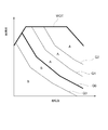
本実施形態における判定条件について、図10を参照しながら説明する。図10に示されるのは、内燃機関20の運転状態と、冷却水の受熱量との関係を示すマップである。冷却水の受熱量とは、循環流路510を循環する冷却水に対して単位時間あたりに加えられる熱量のことである。マップの横軸には内燃機関20の回転数が示されており、縦軸には、内燃機関20に取り込まれる空気量が示されている。図10では、横軸の回転数及び縦軸の空気量で定まる運転状態毎に、当該状態における受熱量が等高線で描かれている。図10のマップは予め作成され、診断装置100が有するROMに記憶されている。
Determination conditions in the present embodiment will be described with reference to FIG. FIG. 10 shows a map showing the relationship between the operating state of the
太線WOTで示されるのは、それぞれの回転数において内燃機関20に取り込まれる空気量の上限値、すなわち、スロットルバルブが全開の状態で内燃機関20に取り込まれる空気の流量である。
The thick line WOT indicates the upper limit value of the amount of air taken into the
図10の線Q0に沿うような運転状態のときには、冷却水の受熱量は、単位時間あたりに冷却水から外部に放出される熱量(以下、「放熱量」とも表記する)と概ね一致する。一方、図10の線Q1に沿うような運転状態のときには、冷却水の受熱量は放熱量よりも大きくなる。このため、ラジエータ530を冷却水が通らない場合には、冷却水の温度は上昇傾向となる。
In the operation state along the line Q0 in FIG. 10, the amount of heat received from the cooling water substantially coincides with the amount of heat released from the cooling water to the outside per unit time (hereinafter also referred to as “heat dissipation amount”). On the other hand, in the operation state along line Q1 in FIG. 10, the amount of heat received by the cooling water is greater than the amount of heat released. For this reason, when the cooling water does not pass through the
また、図10の線Q2に沿うような運転状態のときには、冷却水の受熱量は更に大きくなる。このため、ラジエータ530を冷却水が通らない場合には、冷却水の温度は更に上昇傾向となる。
Further, in the operation state along the line Q2 in FIG. 10, the heat receiving amount of the cooling water is further increased. For this reason, when the cooling water does not pass through the
図10の線Q3に沿うような運転状態のときには、冷却水の受熱量は放熱量よりも小さくなる。このため、ラジエータ530を冷却水が通らない場合であっても、冷却水の温度は低下傾向となる可能性がある。
In the operating state along line Q3 in FIG. 10, the amount of heat received by the cooling water is smaller than the amount of heat released. For this reason, even if the cooling water does not pass through the
このように、図10に示されるマップでは、内燃機関20の運転領域が右上にあるほど、冷却水の受熱量は大きな値となる。逆に、内燃機関20の運転領域が左下にあるほど、冷却水の受熱量は小さな値となる。尚、内燃機関20で生じるトルクをマップの縦軸としてもよい。その場合でも、概ね図10と同様のマップが描かれることとなる。
As described above, in the map shown in FIG. 10, the amount of heat received by the cooling water increases as the operating range of the
以下では、線Q0よりも上方側となる運転領域、すなわち、図10において符号Aが付されている運転領域のことを「A領域」と称する。また、線Q0よりも下方側となる運転領域、すなわち、図10において符号Bが付されている運転領域のことを「B領域」と称する。A領域は、冷却水の受熱量が放熱量よりも大きくなるような運転領域である。また、B領域は、冷却水の受熱量が放熱量よりも小さくなるような運転領域である。 In the following, the operation region above the line Q0, that is, the operation region to which the reference symbol A is attached in FIG. 10 is referred to as “A region”. In addition, an operation region on the lower side than the line Q0, that is, an operation region to which a symbol B is attached in FIG. 10 is referred to as “B region”. Region A is an operation region in which the amount of heat received from the cooling water is greater than the amount of heat released. Further, the region B is an operation region in which the amount of heat received from the cooling water is smaller than the amount of heat released.
既に述べたように、冷却水が低温となっているときには、温度調整弁560に異常が生じている可能性がある。しかしながら、温度調整弁560が正常なときであっても、B領域で運転が行われているのであれば冷却水の温度は上昇しにくい。
As already described, when the cooling water is at a low temperature, the
つまり、B領域の運転頻度が高いときには、冷却水の温度が判定閾値を下回っていたとしても、その原因が温度調整弁560に異常が生じているとは限らない。そこで、本実施形態では、B領域の運転頻度が高いときには、図9のステップS26において判定条件が不成立とされる。一方、A領域の運転頻度が高いときには、判定条件が成立とされる。
That is, when the operation frequency of the region B is high, even if the temperature of the cooling water is below the determination threshold, the cause does not necessarily mean that the
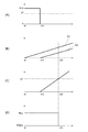
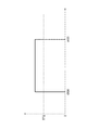
図11を参照しながら、判定条件が不成立とされる場合の例について説明する。図11(A)には、内燃機関20で発生するトルクの変化が示されている。図11(A)の例では、時刻t0から時刻t10までの期間において、閾値NTよりも高い値N10のトルクが発生している。このとき、内燃機関20の運転領域は、受熱量の大きなA領域となっている。
An example in which the determination condition is not satisfied will be described with reference to FIG. FIG. 11A shows a change in torque generated in the
時刻t10以降においては、内燃機関20が停止し、車両10はモーターMの駆動力のみによって走行する。内燃機関20のトルクは0となり、閾値NTよりも小さくなる。これ以降、内燃機関20の運転領域は、受熱量の小さなB領域となる。
After time t10, the
図11(B)には、時刻t0以降における運転時間の積算値を示す線G1と、B領域での運転が行われている時間の積算値を示す線G2とが示されている。また、図11(C)には、運転時間の積算値に対する、B領域での運転が行われている時間の積算値、の比率の変化が示されている。つまり、線G1で示される値に対する、線G2で示される値の比率の変化が示されている。時刻t10以降は、B領域で運転されることにより当該比率が次第に大きくなって行く。 FIG. 11B shows a line G1 indicating the integrated value of the operation time after time t0 and a line G2 indicating the integrated value of the time during which operation is performed in the B region. FIG. 11C shows a change in the ratio of the integrated value of the time during which the operation is performed in the region B to the integrated value of the operating time. That is, a change in the ratio of the value indicated by the line G2 to the value indicated by the line G1 is shown. After the time t10, the ratio gradually increases by operating in the B region.
B領域で運転される比率が所定の閾値STを超えると、異常判定部120は判定条件を不成立とする。図11(D)は、判定条件が成立とされている状態から、不成立とされている状態に切り替わる様子を示すグラフである。図11の例では、時刻t20においてB領域の比率が閾値STを超えており、同時刻以降においては判定条件が成立とされる。尚、本実施形態では、閾値STとして50%が設定されている。
When the ratio operated in the B region exceeds a predetermined threshold ST, the
以上のような、B領域で運転されている時間の積算や、当該積算値の比率の算出は、冷却水の温度の測定値によることなく、診断装置100においては継続的に行われている。
The integration of the time during which the operation is performed in the region B and the calculation of the ratio of the integration values as described above are continuously performed in the
尚、以上の説明においては、A領域とB領域との境界を示す線Q0(図10を参照)が固定されているものとして説明したが、当該境界が、現時点における放熱量の推定値に基づいてリアルタイムに変更されるような態様であってもよい。 In the above description, the line Q0 (see FIG. 10) indicating the boundary between the A region and the B region is described as being fixed. However, the boundary is based on the estimated value of the heat dissipation amount at the present time. It may be a mode that is changed in real time.
例えば、冷却水の温度と外気温度、及び内燃機関20の回転数に基づいて、現時点における放熱量を推定することができる。図10のマップで求められる受熱量と、推定される放熱量とを比較して、受熱量の方が大きいときには、現在はA領域での運転が行われていると判断することができる。逆に、放熱量の方が大きいときには、現在はB領域での運転が行われていると判断することができる。
For example, the current heat dissipation amount can be estimated based on the temperature of the cooling water, the outside air temperature, and the rotational speed of the
図9に戻って説明を続ける。ステップS26において判定条件が成立している場合には、ステップS27に移行する。ステップS27では、第1異常フラグ及び第2異常フラグのいずれかがONであるか否かが判定される。第1異常フラグ及び第2異常フラグのいずれかがONであれば、ステップS28に移行する。ステップS28では、第3異常フラグがONに設定される。第3異常フラグとは、診断装置100のRAMに記憶される変数であって、ONまたはOFFのいずれのかの値が設定されるものである。図9の処理が開始される前における第3異常フラグの初期値はOFFとなっている。ステップS28で第3異常フラグがONに設定されると、ステップS31に移行する。
Returning to FIG. 9, the description will be continued. If the determination condition is satisfied in step S26, the process proceeds to step S27. In step S27, it is determined whether one of the first abnormality flag and the second abnormality flag is ON. If either the first abnormality flag or the second abnormality flag is ON, the process proceeds to step S28. In step S28, the third abnormality flag is set to ON. The third abnormality flag is a variable stored in the RAM of the
ステップS27で、第1異常フラグ及び第2異常フラグの両方がOFFであった場合は、ステップS29に移行する。また、ステップS26で判定条件が不成立であった場合にも、ステップS29に移行する。 If both the first abnormality flag and the second abnormality flag are OFF in step S27, the process proceeds to step S29. Also, if the determination condition is not satisfied in step S26, the process proceeds to step S29.
ステップS29では、冷却水が温度調整弁560からラジエータ530に向かう流路が全閉となるように、温度調整弁560の制御が行われる。具体的には、診断装置100から制御装置40に向けて信号が送信される。信号を受信した制御装置40は、温度調整弁560が第1状態又は第2状態に切り換わるように、温度調整弁560に制御信号を送信する。
In step S29, the
このとき、温度調整弁560が正常であるならば、ラジエータ530には冷却水が供給されなくなる。ラジエータ530における冷却水の冷却が行われなくなるので、水温取得部110で取得される冷却水の温度は次第に上昇するはずである。
At this time, if the
逆に温度調整弁560が故障しており、弁体561が動作し得ない状態となっているならば、ラジエータ530に供給される冷却水の流量は変化しない。従って、水温取得部110で取得される冷却水の温度は一定のままとなる。もしくは、ラジエータ530で冷却され続けることにより、冷却水の温度が低下することもある。
On the other hand, if the
そこで、ステップS29に続くステップS30では、水温取得部110で取得される冷却水の温度が上昇するか否かが判定される。
Therefore, in step S30 following step S29, it is determined whether or not the temperature of the cooling water acquired by the water
図12を参照しながら、当該判定の例について説明する。図12には、時刻t300から時刻t400までの期間において図9のステップS29の処理が行われた際における、冷却水の温度の変化の例が示されている。時刻t300以降においては温度調整弁が第2状態となり、ラジエータ530に冷却水が供給されなくなる。従って、冷却水の温度は次第に上昇して行く。
An example of the determination will be described with reference to FIG. FIG. 12 shows an example of a change in the temperature of the cooling water when the process of step S29 of FIG. 9 is performed in the period from time t300 to time t400. After the time t300, the temperature adjustment valve is in the second state, and the cooling water is not supplied to the
図12の例では、時刻t300における冷却水の温度をT10とし、時刻t400における冷却水の温度をT20としている。本実施形態では、図9のステップS29の処理が行われた期間における温度上昇量が、図12の例のように閾値DTを超えた場合には、冷却水の温度が上昇したと判定される。一方、ステップS29の処理が行われた期間における温度上昇量が、閾値DT以下である場合には、ステップS30において冷却水の温度が上昇しなかったと判定される。 In the example of FIG. 12, the temperature of the cooling water at time t300 is T10, and the temperature of the cooling water at time t400 is T20. In the present embodiment, when the temperature increase amount during the period in which the process of step S29 of FIG. 9 is performed exceeds the threshold value DT as in the example of FIG. 12, it is determined that the temperature of the cooling water has increased. . On the other hand, when the temperature increase amount in the period in which the process of step S29 is performed is equal to or less than the threshold value DT, it is determined in step S30 that the temperature of the cooling water has not increased.
ステップS30における判定の他の例について、図13を参照しながら説明する。図13には、時刻t300から時刻t400までの期間において図9のステップS29の処理が行われた際における、冷却水の温度の変化量が示されている。具体的には、現時点における冷却水の温度と、当該時点から1秒前における冷却水の温度との差、の変化が示されている。このように示されるグラフの縦軸は、冷却水の温度の変化速度を示すものともいえる。 Another example of the determination in step S30 will be described with reference to FIG. FIG. 13 shows the amount of change in the temperature of the cooling water when the process of step S29 of FIG. 9 is performed in the period from time t300 to time t400. Specifically, the change in the difference between the temperature of the cooling water at the present time and the temperature of the cooling water one second before that time is shown. It can be said that the vertical axis of the graph thus shown indicates the rate of change in the temperature of the cooling water.
図13の例では、時刻t300から時刻t400までの期間におけるグラフの値が所定の閾値TT2を超えた場合に、冷却水の温度が上昇したと判定される。一方、同期間におけるグラフの値が閾値TT2を超えなかった場合には、ステップS30において冷却水の温度が上昇しなかったと判定される。このように、冷却水の温度の変化速度と、所定の閾値TT2とを比較することによって、冷却水の温度が上昇したか否かの判定が行われてもよい。 In the example of FIG. 13, when the value of the graph in the period from time t300 to time t400 exceeds a predetermined threshold value TT2, it is determined that the temperature of the cooling water has increased. On the other hand, when the value of the graph during the same period does not exceed the threshold value TT2, it is determined in step S30 that the temperature of the cooling water has not increased. In this way, it may be determined whether or not the temperature of the cooling water has increased by comparing the change rate of the temperature of the cooling water with the predetermined threshold value TT2.
図9に戻って説明を続ける。ステップS30において、水温が上昇しなかったと判定された場合には、ステップS28に移行し、第3異常フラグがONに設定される。水温が上昇したと判定された場合には、ステップS31に移行する。このように、ステップS29においてラジエータ530への冷却水の供給を停止する制御が行われた後、冷却水の温度の変化に基づいて温度調整弁560の異常が判定される。
Returning to FIG. 9, the description will be continued. If it is determined in step S30 that the water temperature has not risen, the process proceeds to step S28, and the third abnormality flag is set to ON. If it is determined that the water temperature has risen, the process proceeds to step S31. As described above, after the control for stopping the supply of the cooling water to the
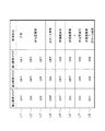
ステップS31では、第1異常フラグ、第2異常フラグ、及び第3異常フラグのそれぞれの設定状態に基づいて、温度調整弁560の故障状況についての最終判定がなされる。具体的には、図14に示される対応表に基づいて、温度調整弁560の故障状況が判定される。
In step S31, a final determination is made regarding the failure status of the
符号L1が付された1行目のように、第1異常フラグ、第2異常フラグ、及び第3異常フラグの全てがOFFであった場合には、温度調整弁560は正常であると判定される。これに対し、第1異常フラグ、第2異常フラグ、及び第3異常フラグのうち少なくとも一つがONであった場合には、温度調整弁560に何らかの異常が生じたと判定される。
If all of the first abnormality flag, the second abnormality flag, and the third abnormality flag are OFF as in the first line with the symbol L1, the
符号L2が付された2行目のように、第1異常フラグのみがONであり、第2異常フラグ及び第3異常フラグがいずれもOFFであった場合には、温度調整弁560の弁体561が動作し得ない状態になっていると判定される。このような異常状態のことを、以下では「弁位置異常」とも称する。
When only the first abnormality flag is ON and both the second abnormality flag and the third abnormality flag are OFF as in the second row with the reference L2, the valve body of the
符号L3が付された3行目のように、第1異常フラグ及び第2異常フラグがONであり、第3異常フラグがOFFであった場合にも、弁位置異常であると判定される。 As shown in the third line with the symbol L3, when the first abnormality flag and the second abnormality flag are ON and the third abnormality flag is OFF, it is determined that the valve position is abnormal.
符号L4が付された4行目のように、第2異常フラグのみがONであり、第1異常フラグ及び第3異常フラグがいずれもOFFであった場合には、温度調整弁560の内部で亀裂が生じる等により、冷却水が漏れている状態であると判定される。このような異常状態のことを、以下では「弁リーク異常」とも称する。
When only the second abnormality flag is ON and both the first abnormality flag and the third abnormality flag are OFF as shown in the fourth line with the symbol L4, the
符号L5が付された5行目のように、第1異常フラグ及び第2異常フラグのいずれもがOFFであり、第3異常フラグがONであった場合には、これまでに述べた弁位置異常や弁リーク異常とは別の異常が、温度調整弁560において生じていると判定される。このような異常状態のことを総じて、以下では「弁機能異常」とも称する。
When the first abnormality flag and the second abnormality flag are both OFF and the third abnormality flag is ON as in the fifth line with the symbol L5, the valve position described so far It is determined that an abnormality other than the abnormality or the valve leak abnormality has occurred in the
符号L6が付された6行目のように、第2異常フラグのみがOFFであり、第1異常フラグ及び第3異常フラグがいずれもONであった場合には、弁機能異常と弁位置異常とが組み合わさって生じていると判定される。また、符号L7が付された7行目のように、第1異常フラグ、第2異常フラグ、及び第3異常フラグの全てがONであった場合にも、弁機能異常と弁位置異常とが組み合わさって生じていると判定される。 When only the second abnormality flag is OFF and both the first abnormality flag and the third abnormality flag are ON, as shown in the sixth line with the symbol L6, the valve function abnormality and the valve position abnormality are detected. Is determined to occur in combination. In addition, as shown in the seventh line with the reference L7, when all of the first abnormality flag, the second abnormality flag, and the third abnormality flag are ON, the valve function abnormality and the valve position abnormality may occur. It is determined that a combination has occurred.
符号L8が付された8行目のように、第1異常フラグのみがOFFであり、第2異常フラグ及び第3異常フラグがいずれもONであった場合には、弁機能異常と弁リーク異常とが組み合わさって生じていると判定される。 When only the first abnormality flag is OFF and both the second abnormality flag and the third abnormality flag are ON, as shown in the eighth line with the symbol L8, the valve function abnormality and the valve leak abnormality are detected. Is determined to occur in combination.
以上のように、本実施形態に係る診断装置100では、冷却水の温度と目標温度との差である水温偏差のみならず、弁体位置と目標位置との差である位置偏差にも基づいて、温度調整弁560の異常が判定される。温度調整弁560の異常による位置偏差への影響は、水温偏差への影響に比べて短時間のうちに現れる。このため、診断装置100によれば、温度調整弁560に異常が生じたことを短時間のうちに検知することが可能となっている。
As described above, in the
また、水温偏差が異常であることを示す第1異常フラグ、位置偏差が異常であることを示す第2異常フラグ、及び、温度調整弁560の機能に異常が生じていることを示す第3異常フラグ、の組み合わせに基づいて、温度調整弁560の故障状況(つまり、生じている異常の種類)が判定される。このように、単に温度調整弁560に異常が生じていることのみの判定ではなく、当該異常の種類を判定することも可能となっている。
Also, a first abnormality flag indicating that the water temperature deviation is abnormal, a second abnormality flag indicating that the position deviation is abnormal, and a third abnormality indicating that an abnormality has occurred in the function of the
本発明の第2実施形態について説明する。本実施形態では、位置閾値を設定する方法についてのみ第1実施形態と異なっている。その他の点においては第1実施形態と同じである。 A second embodiment of the present invention will be described. The present embodiment is different from the first embodiment only in the method for setting the position threshold value. Other points are the same as those of the first embodiment.
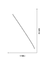
図15には、蓄電池電圧と、これに応じて設定される位置閾値との関係が示されている。図15に示されるように、本実施形態においても、蓄電池電圧が大きくなるほど位置閾値は小さな値に変更される。ただし、蓄電池電圧が所定の電圧値VTを超えているときには、蓄電池電圧が大きくなるほど位置閾値も大きな値に変更される。 FIG. 15 shows the relationship between the storage battery voltage and the position threshold value set accordingly. As FIG. 15 shows, also in this embodiment, a position threshold value is changed into a small value, so that a storage battery voltage becomes large. However, when the storage battery voltage exceeds the predetermined voltage value VT, the position threshold value is changed to a larger value as the storage battery voltage increases.
蓄電池電圧が大きいときには、弁体561の動作速度が速くなる。このため、弁体位置が変更された際には、弁体位置のオーバーシュートが生じる可能性がある。このようなオーバーシュートが生じると、温度調整弁560には何ら異常が生じていないにも拘らず、一時的に位置偏差が大きくなってしまい、位置偏差が異常であると判定されてしまう可能性がある。
When the storage battery voltage is large, the operating speed of the
そこで、オーバーシュートが比較的生じやすい構成の温度調整弁560が用いられる場合には、図15のように位置閾値を設定し、蓄電池電圧が大きいときにおいて異常と判定されにくくした方が望ましい。
Therefore, when the
本発明の第3実施形態について説明する。本実施形態でも、位置閾値を設定する方法についてのみ第1実施形態と異なっている。その他の点においては第1実施形態と同じである。 A third embodiment of the present invention will be described. Also in the present embodiment, only the method for setting the position threshold is different from that in the first embodiment. Other points are the same as those of the first embodiment.
図16には、水温取得部110で取得される冷却水の温度と、これに応じて設定される位置閾値との関係が示されている。図16に示されるように、冷却水の温度が高くなるほど、位置閾値は小さな値に変更される。換言すれば、冷却水の温度が低くなるほど、位置閾値は大きな値に変更される。
FIG. 16 shows the relationship between the temperature of the cooling water acquired by the water
冷却水の温度が低いときには、冷却水の動粘度が高くなるので、弁体561の応答速度が低下しやすくなる。その結果、温度調整弁560の動作中における位置偏差が大きくなる傾向がある。このため、温度調整弁560には何ら異常が生じていないにも拘らず、一時的に位置偏差が大きくなってしまい、位置偏差が異常であると判定されてしまう可能性がある。
When the temperature of the cooling water is low, the kinematic viscosity of the cooling water is high, so that the response speed of the
そこで、図16のように、冷却水の温度が低くなるほど位置閾値を大きな値に変更することとすれば、冷却水の温度が低くなり動粘度が高くなったときに、位置偏差が異常であるとの誤判定が生じることを防止することができる。 Therefore, as shown in FIG. 16, if the position threshold value is changed to a larger value as the temperature of the cooling water becomes lower, the position deviation is abnormal when the temperature of the cooling water becomes lower and the kinematic viscosity becomes higher. It is possible to prevent the erroneous determination of
本発明の第4実施形態について説明する。本実施形態では、水温閾値を設定する方法についてのみ第1実施形態と異なっている。その他の点においては第1実施形態と同じである。 A fourth embodiment of the present invention will be described. This embodiment is different from the first embodiment only in the method for setting the water temperature threshold. Other points are the same as those of the first embodiment.
本実施形態では、暖房装置550の運転が行われているときには、暖房装置550の運転が行われていないときに比べて、水温閾値が大きくなるように変更される。図17に示される例では、時刻t10において暖房装置550の運転が開始されると、水温閾値は、値OT1から、これよりも大きな値OT2に変更される。
In this embodiment, when the operation of the
暖房装置550の運転が行われているときには、冷却水がヒータコア551を通過する際において奪われる熱量が大きくなる。これにより、冷却水の温度は比較的不安定となり、水温偏差が大きくなる傾向がある。このため、温度調整弁560には何ら異常が生じていないにも拘らず、一時的に水温偏差が大きくなってしまい、水温偏差が異常であると判定されてしまう可能性がある。
When the
そこで、図17に示されるように、暖房装置550の運転が行われているときには水温閾値を大きな値に変更することとすれば、水温偏差が異常であるとの誤判定が生じることを防止することができる。
Therefore, as shown in FIG. 17, if the water temperature threshold is changed to a large value when the
本発明の第5実施形態について説明する。本実施形態も、水温閾値を設定する方法についてのみ第1実施形態と異なっている。その他の点においては第1実施形態と同じである。 A fifth embodiment of the present invention will be described. This embodiment is also different from the first embodiment only in the method for setting the water temperature threshold. Other points are the same as those of the first embodiment.
図18(A)に示されるのは、水温取得部110で取得される冷却水の温度の変化である。また、図18(B)に示されるのは、温度調整弁560からラジエータ530に向かう流路の開度の変化である。図18(B)に示される例では、時刻t10において第3状態から第2状態に切り換えられており、その後の時刻t20において第2状態から再び第3状態に切り換えられている。つまり、時刻t10から時刻t20までの期間においては、ラジエータ530への冷却水の供給が一時的に停止されている。
What is shown in FIG. 18A is a change in the temperature of the cooling water acquired by the water
当該期間においては、水温取得部110で取得される冷却水の温度は次第に高くなって行く。ただし、ラジエータ530の内部では、滞留している冷却水は冷却され続けているので、その温度は低くなっている。
In the said period, the temperature of the cooling water acquired by the water
時刻t20となり第3状態に切り換えられると、ラジエータ530の内部に滞留していた低温の冷却水が、内燃機関20に供給される。このため、図18(A)に示されるように、水温取得部110で取得される冷却水の温度が一気に低下して、アンダーシュートが生じることがある。ラジエータ530への冷却水の供給が停止されていた期間、すなわち、時刻t10から時刻t20までの閉弁期間TM1が長くなるほど、上記のようなアンダーシュートは大きくなる傾向がある。
When the time t20 is reached and the state is switched to the third state, the low-temperature cooling water staying in the
アンダーシュートが大きくなると、当然ながら水温偏差も大きくなる。このため、温度調整弁560には何ら異常が生じていないにも拘らず、一時的に水温偏差が大きくなってしまい、水温偏差が異常であると判定されてしまう可能性がある。
As the undershoot increases, the water temperature deviation naturally increases. For this reason, although there is no abnormality in the
そこで、本実施形態では、閉弁期間の長さに応じて水温閾値が変更される。具体的には、図19に示されるように、閉弁期間が長くなるほど、水温閾値が大きくなるように変更される。このため、図18(A)のような水温のアンダーシュートが生じた際に、水温偏差が異常であるとの誤判定が生じることを防止することができる。 Therefore, in this embodiment, the water temperature threshold is changed according to the length of the valve closing period. Specifically, as shown in FIG. 19, the water temperature threshold is changed as the valve closing period becomes longer. For this reason, when the water temperature undershoot as shown in FIG. 18A occurs, it is possible to prevent an erroneous determination that the water temperature deviation is abnormal.
以上、具体例を参照しつつ本発明の実施の形態について説明した。しかし、本発明はこれらの具体例に限定されるものではない。すなわち、これら具体例に、当業者が適宜設計変更を加えたものも、本発明の特徴を備えている限り、本発明の範囲に包含される。例えば、前述した各具体例が備える各要素およびその配置、材料、条件、形状、サイズなどは、例示したものに限定されるわけではなく適宜変更することができる。また、前述した各実施の形態が備える各要素は、技術的に可能な限りにおいて組み合わせることができ、これらを組み合わせたものも本発明の特徴を含む限り本発明の範囲に包含される。 The embodiments of the present invention have been described above with reference to specific examples. However, the present invention is not limited to these specific examples. In other words, those specific examples that have been appropriately modified by those skilled in the art are also included in the scope of the present invention as long as they have the characteristics of the present invention. For example, the elements included in each of the specific examples described above and their arrangement, materials, conditions, shapes, sizes, and the like are not limited to those illustrated, but can be changed as appropriate. Moreover, each element with which each embodiment mentioned above is provided can be combined as long as technically possible, and the combination of these is also included in the scope of the present invention as long as it includes the features of the present invention.
10:車両
20:内燃機関
100:診断装置
110:水温取得部
120:異常判定部
550:暖房装置
560:温度調整弁
561:弁体
BT:蓄電池
DESCRIPTION OF SYMBOLS 10: Vehicle 20: Internal combustion engine 100: Diagnosis apparatus 110: Water temperature acquisition part 120: Abnormality determination part 550: Heating apparatus 560: Temperature adjustment valve 561: Valve body BT: Storage battery
Claims (9)
前記車両の内燃機関(20)から排出される冷却水の温度を取得する水温取得部(110)と、
前記冷却水の温度を調整するものとして前記車両に設けられている温度調整弁(560)、の異常を判定する異常判定部(120)と、を備え、
前記温度調整弁は、
電力の供給を受けて内部の弁体(561)を動作させ、その開度を変化させるように構成されており、且つ、前記車両の運転が行われる際には、前記弁体の位置を目標位置に一致させ、これにより前記冷却水の温度を目標温度に一致させる制御が行われるものであって、
前記異常判定部が、
前記弁体の位置と前記目標位置との差である位置偏差と、
前記冷却水の温度と前記目標温度との差である水温偏差と、に基づいて、前記温度調整弁の異常を判定し、
前記異常判定部が、
前記位置偏差又はその積算値、の絶対値が所定の位置閾値を超えると、前記温度調整弁に異常が生じたと判定し、
前記車両に備えられた蓄電池(BT)の電圧が大きくなるほど、前記位置閾値を小さくなるように変更する診断装置。 A diagnostic device provided in a vehicle (10),
A water temperature acquisition unit (110) for acquiring the temperature of cooling water discharged from the internal combustion engine (20) of the vehicle;
An abnormality determination unit (120) for determining an abnormality of a temperature adjustment valve (560) provided in the vehicle as an apparatus for adjusting the temperature of the cooling water,
The temperature regulating valve is
It is configured to operate the internal valve body (561) in response to the supply of electric power to change the opening thereof, and when the vehicle is operated, the position of the valve body is set as a target. Control to match the position and thereby the temperature of the cooling water to match the target temperature,
The abnormality determination unit
A position deviation which is a difference between the position of the valve body and the target position;
Based on the water temperature deviation that is the difference between the temperature of the cooling water and the target temperature, the abnormality of the temperature adjustment valve is determined ,
The abnormality determination unit
When the absolute value of the position deviation or its integrated value exceeds a predetermined position threshold, it is determined that an abnormality has occurred in the temperature adjustment valve,
The diagnostic device which changes so that the position threshold may become small, so that the voltage of the storage battery (BT) with which the vehicle was equipped becomes large .
前記車両の内燃機関(20)から排出される冷却水の温度を取得する水温取得部(110)と、
前記冷却水の温度を調整するものとして前記車両に設けられている温度調整弁(560)、の異常を判定する異常判定部(120)と、を備え、
前記温度調整弁は、
電力の供給を受けて内部の弁体(561)を動作させ、その開度を変化させるように構成されており、且つ、前記車両の運転が行われる際には、前記弁体の位置を目標位置に一致させ、これにより前記冷却水の温度を目標温度に一致させる制御が行われるものであって、
前記異常判定部が、
前記弁体の位置と前記目標位置との差である位置偏差と、
前記冷却水の温度と前記目標温度との差である水温偏差と、に基づいて、前記温度調整弁の異常を判定し、
前記異常判定部が、
前記位置偏差又はその積算値、の絶対値が所定の位置閾値を超えると、前記温度調整弁に異常が生じたと判定し、
前記冷却水の温度が高くなるほど、前記位置閾値を小さくなるように変更する診断装置。 A diagnostic device provided in a vehicle (10),
A water temperature acquisition unit (110) for acquiring the temperature of cooling water discharged from the internal combustion engine (20) of the vehicle;
An abnormality determination unit (120) for determining an abnormality of a temperature adjustment valve (560) provided in the vehicle as an apparatus for adjusting the temperature of the cooling water,
The temperature regulating valve is
It is configured to operate the internal valve body (561) in response to the supply of electric power to change the opening thereof, and when the vehicle is operated, the position of the valve body is set as a target. Control to match the position and thereby the temperature of the cooling water to match the target temperature,
The abnormality determination unit
A position deviation which is a difference between the position of the valve body and the target position;
Based on the water temperature deviation that is the difference between the temperature of the cooling water and the target temperature, the abnormality of the temperature adjustment valve is determined,
The abnormality determination unit
When the absolute value of the position deviation or its integrated value exceeds a predetermined position threshold, it is determined that an abnormality has occurred in the temperature adjustment valve,
The temperature of the cooling water, the higher the cross-sectional device diagnosis to change so as to decrease the position threshold.
前記水温偏差又はその積算値、の絶対値が所定の水温閾値を超えると、前記温度調整弁に異常が生じたと判定する、請求項1又は2に記載の診断装置。 The abnormality determination unit
The diagnostic device according to claim 1 or 2 , wherein when the absolute value of the water temperature deviation or an integrated value thereof exceeds a predetermined water temperature threshold, it is determined that an abnormality has occurred in the temperature adjustment valve.
前記車両の内燃機関(20)から排出される冷却水の温度を取得する水温取得部(110)と、
前記冷却水の温度を調整するものとして前記車両に設けられている温度調整弁(560)、の異常を判定する異常判定部(120)と、を備え、
前記温度調整弁は、
電力の供給を受けて内部の弁体(561)を動作させ、その開度を変化させるように構成されており、且つ、前記車両の運転が行われる際には、前記弁体の位置を目標位置に一致させ、これにより前記冷却水の温度を目標温度に一致させる制御が行われるものであって、
前記異常判定部が、
前記弁体の位置と前記目標位置との差である位置偏差と、
前記冷却水の温度と前記目標温度との差である水温偏差と、に基づいて、前記温度調整弁の異常を判定し、
前記異常判定部が、
前記水温偏差又はその積算値、の絶対値が所定の水温閾値を超えると、前記温度調整弁に異常が生じたと判定し、
前記車両に備えられたラジエータへの前記冷却水の供給が停止されている時間、である閉弁時間が長くなるほど、前記水温閾値を大きくなるように変更する診断装置。 A diagnostic device provided in a vehicle (10),
A water temperature acquisition unit (110) for acquiring the temperature of cooling water discharged from the internal combustion engine (20) of the vehicle;
An abnormality determination unit (120) for determining an abnormality of a temperature adjustment valve (560) provided in the vehicle as an apparatus for adjusting the temperature of the cooling water,
The temperature regulating valve is
It is configured to operate the internal valve body (561) in response to the supply of electric power to change the opening thereof, and when the vehicle is operated, the position of the valve body is set as a target. Control to match the position and thereby the temperature of the cooling water to match the target temperature,
The abnormality determination unit
A position deviation which is a difference between the position of the valve body and the target position;
Based on the water temperature deviation that is the difference between the temperature of the cooling water and the target temperature, the abnormality of the temperature adjustment valve is determined,
The abnormality determination unit
When the absolute value of the water temperature deviation or its integrated value exceeds a predetermined water temperature threshold, it is determined that an abnormality has occurred in the temperature adjustment valve,
The time the supply of cooling water is stopped, the more closed time increases a cross-sectional device diagnosis to change so as to increase the temperature threshold to a radiator provided in the vehicle.
前記車両の内燃機関(20)から排出される冷却水の温度を取得する水温取得部(110)と、
前記冷却水の温度を調整するものとして前記車両に設けられている温度調整弁(560)、の異常を判定する異常判定部(120)と、を備え、
前記温度調整弁は、
電力の供給を受けて内部の弁体(561)を動作させ、その開度を変化させるように構成されており、且つ、前記車両の運転が行われる際には、前記弁体の位置を目標位置に一致させ、これにより前記冷却水の温度を目標温度に一致させる制御が行われるものであって、
前記異常判定部が、
前記弁体の位置と前記目標位置との差である位置偏差と、
前記冷却水の温度と前記目標温度との差である水温偏差と、に基づいて、前記温度調整弁の異常を判定し、
前記異常判定部が、
前記位置偏差と前記水温偏差とに基づいて、前記温度調整弁において生じている異常の種類を判定する診断装置。 A diagnostic device provided in a vehicle (10),
A water temperature acquisition unit (110) for acquiring the temperature of cooling water discharged from the internal combustion engine (20) of the vehicle;
An abnormality determination unit (120) for determining an abnormality of a temperature adjustment valve (560) provided in the vehicle as an apparatus for adjusting the temperature of the cooling water,
The temperature regulating valve is
It is configured to operate the internal valve body (561) in response to the supply of electric power to change the opening thereof, and when the vehicle is operated, the position of the valve body is set as a target. Control to match the position and thereby the temperature of the cooling water to match the target temperature,
The abnormality determination unit
A position deviation which is a difference between the position of the valve body and the target position;
Based on the water temperature deviation that is the difference between the temperature of the cooling water and the target temperature, the abnormality of the temperature adjustment valve is determined,
The abnormality determination unit
On the basis of the position deviation and said temperature difference, the temperature adjusting sectional device diagnosis you determine the type of abnormality occurring in the valve.
その後における前記冷却水の温度の変化、に基づいて前記温度調整弁の異常を判定する、請求項1乃至7のいずれか1項に記載の診断装置。 The temperature control valve is controlled so that the supply of the cooling water to the radiator provided in the vehicle is stopped;
The change in temperature of the cooling water in then determines an abnormality of the temperature adjusting valve on the basis of the diagnostic device according to any one of claims 1 to 7.
Priority Applications (2)
| Application Number | Priority Date | Filing Date | Title |
|---|---|---|---|
| JP2015186707A JP6471663B2 (en) | 2015-09-24 | 2015-09-24 | Diagnostic equipment |
| US15/220,493 US10519875B2 (en) | 2015-07-28 | 2016-07-27 | Diagnostic device |
Applications Claiming Priority (1)
| Application Number | Priority Date | Filing Date | Title |
|---|---|---|---|
| JP2015186707A JP6471663B2 (en) | 2015-09-24 | 2015-09-24 | Diagnostic equipment |
Publications (2)
| Publication Number | Publication Date |
|---|---|
| JP2017061868A JP2017061868A (en) | 2017-03-30 |
| JP6471663B2 true JP6471663B2 (en) | 2019-02-20 |
Family
ID=58429361
Family Applications (1)
| Application Number | Title | Priority Date | Filing Date |
|---|---|---|---|
| JP2015186707A Active JP6471663B2 (en) | 2015-07-28 | 2015-09-24 | Diagnostic equipment |
Country Status (1)
| Country | Link |
|---|---|
| JP (1) | JP6471663B2 (en) |
Families Citing this family (1)
| Publication number | Priority date | Publication date | Assignee | Title |
|---|---|---|---|---|
| KR102385096B1 (en) | 2017-03-27 | 2022-04-12 | 주식회사 다이셀 | Manufacturing method of resin molded article and manufacturing method of optical part |
Family Cites Families (5)
| Publication number | Priority date | Publication date | Assignee | Title |
|---|---|---|---|---|
| JP3809738B2 (en) * | 1998-02-04 | 2006-08-16 | マツダ株式会社 | Engine cooling device abnormality diagnosis device |
| JP2000303842A (en) * | 1999-04-21 | 2000-10-31 | Honda Motor Co Ltd | Engine cooling control device |
| JP2003269171A (en) * | 2002-03-15 | 2003-09-25 | Denso Corp | Water temperature control valve failure detection device |
| JP3849707B2 (en) * | 2005-02-04 | 2006-11-22 | 株式会社デンソー | In-cylinder injection internal combustion engine control device |
| JP5083269B2 (en) * | 2009-04-01 | 2012-11-28 | トヨタ自動車株式会社 | Failure diagnosis device for cooling system |
-
2015
- 2015-09-24 JP JP2015186707A patent/JP6471663B2/en active Active
Also Published As
| Publication number | Publication date |
|---|---|
| JP2017061868A (en) | 2017-03-30 |
Similar Documents
| Publication | Publication Date | Title |
|---|---|---|
| JP6102867B2 (en) | Internal combustion engine cooling device and internal combustion engine cooling device failure diagnosis method | |
| KR101875620B1 (en) | Engine cooling system and electronic thermostat control system and method thereof | |
| JP5987844B2 (en) | vehicle | |
| JP6337032B2 (en) | Thermostat failure detection device | |
| US8839665B2 (en) | Apparatus, vehicle, and method for determining a thermostat malfunction in an engine cooling system | |
| KR20190043202A (en) | Fail-safe controlled method for cooling system of vehicles | |
| JP5839021B2 (en) | Cooling device for internal combustion engine | |
| US9708964B2 (en) | Cooling apparatus for engine | |
| JP6680380B2 (en) | Diagnostic device | |
| KR101714176B1 (en) | Diagnostic method of thermostat | |
| JP2015081566A (en) | Cooling device for internal combustion engine | |
| KR102452470B1 (en) | Fault diagnosis method of coolant temperature sensor for vehicles | |
| JP2017067017A (en) | Cooling control device | |
| JP6040908B2 (en) | vehicle | |
| JP6471663B2 (en) | Diagnostic equipment | |
| JP2017067014A (en) | Cooling control device | |
| JP6418112B2 (en) | Diagnostic equipment | |
| CN114251170B (en) | Method for preventing engine from overheating based on temperature of cooling liquid and engine system thereof | |
| KR102041920B1 (en) | System and method for turbo charger cooling | |
| US10508587B2 (en) | Controlling coolant fluid in a vehicle cooling system using a secondary coolant pump | |
| JP2020094590A (en) | Diagnostic device | |
| JP6500718B2 (en) | Diagnostic device | |
| JP5783076B2 (en) | Engine cooling system | |
| JP6028708B2 (en) | vehicle | |
| KR101562194B1 (en) | Fault diagnosis method of water temperature controller |
Legal Events
| Date | Code | Title | Description |
|---|---|---|---|
| A621 | Written request for application examination |
Free format text: JAPANESE INTERMEDIATE CODE: A621 Effective date: 20171115 |
|
| A131 | Notification of reasons for refusal |
Free format text: JAPANESE INTERMEDIATE CODE: A131 Effective date: 20180703 |
|
| A977 | Report on retrieval |
Free format text: JAPANESE INTERMEDIATE CODE: A971007 Effective date: 20180628 |
|
| A521 | Request for written amendment filed |
Free format text: JAPANESE INTERMEDIATE CODE: A523 Effective date: 20180808 |
|
| TRDD | Decision of grant or rejection written | ||
| A01 | Written decision to grant a patent or to grant a registration (utility model) |
Free format text: JAPANESE INTERMEDIATE CODE: A01 Effective date: 20181225 |
|
| A61 | First payment of annual fees (during grant procedure) |
Free format text: JAPANESE INTERMEDIATE CODE: A61 Effective date: 20190107 |
|
| R151 | Written notification of patent or utility model registration |
Ref document number: 6471663 Country of ref document: JP Free format text: JAPANESE INTERMEDIATE CODE: R151 |
|
| R250 | Receipt of annual fees |
Free format text: JAPANESE INTERMEDIATE CODE: R250 |
|
| R250 | Receipt of annual fees |
Free format text: JAPANESE INTERMEDIATE CODE: R250 |
|
| R250 | Receipt of annual fees |
Free format text: JAPANESE INTERMEDIATE CODE: R250 |
|
| R250 | Receipt of annual fees |
Free format text: JAPANESE INTERMEDIATE CODE: R250 |
|
| R250 | Receipt of annual fees |
Free format text: JAPANESE INTERMEDIATE CODE: R250 |