JP6471021B2 - Communications system - Google Patents
Communications system Download PDFInfo
- Publication number
- JP6471021B2 JP6471021B2 JP2015070252A JP2015070252A JP6471021B2 JP 6471021 B2 JP6471021 B2 JP 6471021B2 JP 2015070252 A JP2015070252 A JP 2015070252A JP 2015070252 A JP2015070252 A JP 2015070252A JP 6471021 B2 JP6471021 B2 JP 6471021B2
- Authority
- JP
- Japan
- Prior art keywords
- data
- transmission
- packet
- node
- relay
- Prior art date
- Legal status (The legal status is an assumption and is not a legal conclusion. Google has not performed a legal analysis and makes no representation as to the accuracy of the status listed.)
- Active
Links
Images


Classifications
-
- H—ELECTRICITY
- H04—ELECTRIC COMMUNICATION TECHNIQUE
- H04L—TRANSMISSION OF DIGITAL INFORMATION, e.g. TELEGRAPHIC COMMUNICATION
- H04L41/00—Arrangements for maintenance, administration or management of data switching networks, e.g. of packet switching networks
- H04L41/06—Management of faults, events, alarms or notifications
- H04L41/0677—Localisation of faults
-
- H—ELECTRICITY
- H04—ELECTRIC COMMUNICATION TECHNIQUE
- H04L—TRANSMISSION OF DIGITAL INFORMATION, e.g. TELEGRAPHIC COMMUNICATION
- H04L12/00—Data switching networks
- H04L12/28—Data switching networks characterised by path configuration, e.g. LAN [Local Area Networks] or WAN [Wide Area Networks]
- H04L12/42—Loop networks
- H04L12/427—Loop networks with decentralised control
- H04L12/433—Loop networks with decentralised control with asynchronous transmission, e.g. token ring, register insertion
-
- H—ELECTRICITY
- H04—ELECTRIC COMMUNICATION TECHNIQUE
- H04L—TRANSMISSION OF DIGITAL INFORMATION, e.g. TELEGRAPHIC COMMUNICATION
- H04L49/00—Packet switching elements
- H04L49/10—Packet switching elements characterised by the switching fabric construction
- H04L49/102—Packet switching elements characterised by the switching fabric construction using shared medium, e.g. bus or ring
-
- H—ELECTRICITY
- H04—ELECTRIC COMMUNICATION TECHNIQUE
- H04L—TRANSMISSION OF DIGITAL INFORMATION, e.g. TELEGRAPHIC COMMUNICATION
- H04L69/00—Network arrangements, protocols or services independent of the application payload and not provided for in the other groups of this subclass
- H04L69/22—Parsing or analysis of headers
Landscapes
- Engineering & Computer Science (AREA)
- Computer Networks & Wireless Communication (AREA)
- Signal Processing (AREA)
- Computer Security & Cryptography (AREA)
- Small-Scale Networks (AREA)
- Data Exchanges In Wide-Area Networks (AREA)
Description
本発明は、複数のネットワークノードがリング状に形成されて一方向に通信を行うリング型ネットワークを用いた通信システムに関する。 The present invention relates to a communication system using a ring network in which a plurality of network nodes are formed in a ring shape to perform communication in one direction.
特許文献1には、トークンリング型のループ伝送路に複数のコンピュータが接続されている場合に、ループ伝送路を巡回しているフリートークンを獲得したコンピュータが、ループ伝送路を介して特定のコンピュータに伝送データ及びビジートークンを伝送することが開示されている。
In
上述のように、従来のトークンパッシング方式による通信では、送信権であるフリートークンをループ伝送路(リング型ネットワーク)に巡回させるので、フリートークンを獲得したコンピュータ(ネットワークノード)しか伝送データを伝送することができない。 As described above, in the communication using the conventional token passing method, the free token as the transmission right is circulated to the loop transmission path (ring network), so that only the computer (network node) that has acquired the free token transmits the transmission data. I can't.
一方、イーサネット(登録商標)等では、どのネットワークノードも自由にデータを送信することが可能である。この場合、データ衝突の可能性があるため、衝突回避の方法として、例えば、送信待ち時間をランダムに設定することが考えられる。しかしながら、送信待ち時間をランダムに設定すると、ロボットの体内通信のような低レイテンシが要求される通信システムでは、適用が困難である。 On the other hand, in Ethernet (registered trademark) or the like, any network node can freely transmit data. In this case, since there is a possibility of data collision, as a collision avoidance method, for example, a transmission waiting time may be set at random. However, if the transmission waiting time is set at random, it is difficult to apply to a communication system that requires low latency, such as in-vivo communication of a robot.
そこで、本発明は、データ衝突を発生させることなく、リング型ネットワークの全てのネットワークノードが同時にデータ通信を行うことを可能にすることで、低レイテンシのデータ通信を実現すると共に、ネットワーク効率を向上させることができる通信システムを提供することを目的とする。 Therefore, the present invention realizes low-latency data communication and improves network efficiency by enabling all network nodes of the ring network to simultaneously perform data communication without causing data collision. It is an object of the present invention to provide a communication system that can be used.
本発明は、複数のネットワークノードがリング状に形成されて一方向に通信を行うリング型ネットワークを用いた通信システムに関するものであり、上記の目的を達成するため、前記各ネットワークノードは、データ送出部、データ受信部及び出力切替部を備える。 The present invention relates to a communication system using a ring network in which a plurality of network nodes are formed in a ring shape to perform communication in one direction. In order to achieve the above object, each network node transmits data. Unit, a data receiving unit, and an output switching unit.
この場合、前記データ送出部は、自ネットワークノードが生成したデータを送信データとして送信するデータ送信ブロック、及び、他ネットワークノードから送信された送信データを中継データとして中継するデータ中継ブロックを有する。前記データ受信部は、前記他ネットワークノードから送信された送信データを受信データとして受信する。前記出力切替部は、前記データ送信ブロックが送信した送信データ、又は、前記データ中継ブロックが中継した中継データのうち、いずれか一方のデータを出力データとして切り替え出力する。 In this case, the data transmission unit includes a data transmission block that transmits data generated by the own network node as transmission data, and a data relay block that relays transmission data transmitted from another network node as relay data. The data receiving unit receives transmission data transmitted from the other network node as reception data. The output switching unit switches and outputs one of the transmission data transmitted by the data transmission block and the relay data relayed by the data relay block as output data.
通常、リング型のネットワークトポロジーである前記リング型ネットワークにおいて、前記各ネットワークノードは、送信ラインと受信ラインとに分けて構築されている。従って、前記各ネットワークノードの送信ラインは、データの送信に関して占有権をそれぞれ持っていると考えることができる。 In the ring network, which is usually a ring network topology, each network node is constructed by dividing it into a transmission line and a reception line. Therefore, it can be considered that the transmission line of each network node has an occupation right for data transmission.
そこで、本発明では、前記リング型ネットワークにおける新たなプロトコルとして、前記出力切替部において、前記送信データ又は前記中継データのうち、いずれか一方のデータを前記出力データとして、切り替えて出力する。このような新たなプロトコルを構築したことにより、全てのネットワークノードでは、前記送信データと前記中継データとを衝突させることなく、前記出力データの送信を同時に行うことが可能となる。従って、本発明は、低レイテンシ且つネットワーク効率が向上した通信システムを実現することができる。この結果、本発明では、ファームウェア(F/W)及びハードウェア(H/W)のデータやログデータ等の大容量データについても、従来と比べて短時間で転送することが可能となる。 Therefore, in the present invention, as a new protocol in the ring network, the output switching unit switches and outputs one of the transmission data and the relay data as the output data. By constructing such a new protocol, it becomes possible for all network nodes to simultaneously transmit the output data without causing the transmission data and the relay data to collide. Therefore, the present invention can realize a communication system with low latency and improved network efficiency. As a result, according to the present invention, large-capacity data such as firmware (F / W) and hardware (H / W) data and log data can be transferred in a shorter time than in the past.
また、本発明に係る通信システムは、上記の特徴的な構成を前提として、下記の第1〜第5の特徴をさらに有してもよい。 The communication system according to the present invention may further include the following first to fifth characteristics on the premise of the characteristic configuration described above.
本発明の第1の特徴として、前記出力切替部は、前記データ送信ブロックが送信した送信データを前記出力データとして優先的に出力する。これにより、前記他ネットワークノードからの送信データである前記中継データと、前記自ネットワークノードの送信データとを衝突させることなく、リアルタイムでデータ通信を行うことが可能となる。この結果、全てのネットワークノードが同時にデータ通信を行っても、データ衝突を発生させることなく、高いネットワーク効率でデータ通信を行うことができる。 As a first feature of the present invention, the output switching unit preferentially outputs transmission data transmitted by the data transmission block as the output data. This makes it possible to perform data communication in real time without causing the relay data, which is transmission data from the other network node, to collide with the transmission data of the own network node. As a result, even if all network nodes perform data communication at the same time, data communication can be performed with high network efficiency without causing data collision.
また、第1の特徴において、前記データ中継ブロックは、前記データ送信ブロックが送信した送信データを前記出力切替部が優先的に出力する間、前記中継データを一時的に保持する中継データ保持部を有する。これにより、前記送信データの出力完了後に前記中継データを出力することになるので、前記中継データと前記送信データとの衝突を確実に回避して、ネットワーク効率を向上させることができる。 In the first feature, the data relay block includes a relay data holding unit that temporarily holds the relay data while the output switching unit preferentially outputs the transmission data transmitted by the data transmission block. Have. As a result, the relay data is output after the output of the transmission data is completed, so that collision between the relay data and the transmission data can be reliably avoided and network efficiency can be improved.
さらに、第1の特徴において、前記データ送信ブロックが送信した送信データが前記リング型ネットワークを一周して前記データ送信ブロックに戻ってくるまで、当該データ送信ブロックは、次の送信データの送信を行わない。これにより、前記中継データの送信時間を確保すると共に、前記中継データの中継時間を最小化することが可能となる。また、当該中継データと前記送信データとの衝突を効果的に回避して、ネットワーク効率の向上を図ることもできる。 Furthermore, in the first feature, until the transmission data transmitted by the data transmission block goes around the ring network and returns to the data transmission block, the data transmission block transmits the next transmission data. Absent. Accordingly, it is possible to secure the transmission time of the relay data and minimize the relay time of the relay data. In addition, it is possible to effectively avoid a collision between the relay data and the transmission data, thereby improving network efficiency.
さらにまた、第1の特徴において、前記出力切替部は、データの出力待ちを指示する出力待ち信号を前記データ送信ブロック又は前記データ中継ブロックに出力し、前記データ送信ブロック又は前記データ中継ブロックのうち、前記出力待ち信号の入力されていないブロックが、前記出力切替部にデータを送出する。これにより、前記中継データと前記送信データとの衝突を確実に回避することができる。 Still further, in the first feature, the output switching unit outputs an output waiting signal instructing to wait for data output to the data transmission block or the data relay block, and the data switching block or the data relay block. The block to which the output waiting signal is not input sends data to the output switching unit. Thereby, it is possible to reliably avoid a collision between the relay data and the transmission data.
本発明の第2の特徴として、前記各ネットワークノードのデータ送出部及び出力切替部のうち少なくとも一方は、オンザフライ方式によるデータの出力中、当該データの異常を検出するエラー検出部を有する。この場合、前記エラー検出部が前記データの異常を検出したときに、当該エラー検出部を有する前記データ送出部又は前記出力切替部は、当該データに異常があることを示すエラーデータを前記データに付加して出力する。 As a second feature of the present invention, at least one of the data transmission unit and the output switching unit of each network node has an error detection unit that detects an abnormality of the data during the output of data by the on-the-fly method. In this case, when the error detection unit detects an abnormality in the data, the data sending unit or the output switching unit having the error detection unit adds error data indicating that the data is abnormal to the data. Append and output.
空き時間をできる限り削減して、低レイテンシの通信を実現するために、オンザフライ方式でデータを出力する場合に、異常なデータに対しては前記エラーデータを付加して出力する。この結果、後段のブロックは、前記エラーデータを確認することで、入力されたデータが異常なデータであることを容易に把握し、当該異常なデータを早期に破棄することができる。従って、次に送信する正常なデータをできる限り早く送出することができ、ネットワーク効率の低下を最小限に留めることが可能となる。 In order to reduce idle time as much as possible and realize low-latency communication, when outputting data by the on-the-fly method, the error data is added to the abnormal data and output. As a result, the subsequent block can easily recognize that the input data is abnormal data by confirming the error data, and can discard the abnormal data at an early stage. Therefore, normal data to be transmitted next can be transmitted as soon as possible, and a decrease in network efficiency can be minimized.
また、第2の特徴において、前記エラー検出部が前記データの異常を検出した場合、当該エラー検出部を有する前記データ送出部又は前記出力切替部は、前記データの出力を途中で打ち切り、打ち切った前記データの最後に前記エラーデータを付加して出力する。これにより、後段のブロックにおいて、異常なデータを早期に把握して破棄することが可能となり、ネットワーク効率の低下を確実に抑制することができる。 Further, in the second feature, when the error detection unit detects an abnormality in the data, the data transmission unit or the output switching unit having the error detection unit aborted the output of the data and aborted. The error data is added to the end of the data and output. As a result, abnormal data can be grasped and discarded at an early stage in the subsequent block, and a decrease in network efficiency can be reliably suppressed.
さらに、第2の特徴において、後段の出力切替部又はデータ送出部は、打ち切った前記データを受信し、自己のエラー検出部が前記エラーデータを検出したときに、打ち切った前記データを破棄すると共に、アイドルデータを出力する。これにより、打ち切った前記データが前記リング型ネットワークを巡回し続けることを回避することができる。 Furthermore, in the second feature, the output switching unit or the data sending unit in the subsequent stage receives the aborted data, and discards the aborted data when the error detection unit detects the error data. , Output idle data. Thereby, it is possible to avoid the aborted data from continuing to circulate the ring network.
さらにまた、第2の特徴において、前記エラー検出部は、前記各ネットワークノードのデータ中継ブロックに設けられ、前記エラー検出部が前記中継データの異常を検出した場合、前記データ中継ブロックは、打ち切った前記中継データ及び前記エラーデータを順に出力した後、次の中継データが入力されるまで、他のアイドルデータを出力する。これにより、後段のブロックでは、入力された中継データのうち、前記エラーデータの直前までのデータが異常なデータであることを容易に把握できる。 Furthermore, in the second feature, the error detection unit is provided in a data relay block of each network node, and when the error detection unit detects an abnormality in the relay data, the data relay block is aborted. After the relay data and the error data are output in order, other idle data is output until the next relay data is input. Thereby, in the subsequent block, it is possible to easily grasp that the data up to immediately before the error data is abnormal data among the input relay data.
本発明の第3の特徴において、前記各ネットワークノードのデータ送信ブロックは、前記受信データが前記自ネットワークノードで生成した送信データであるか否かを判定する送信完了判定部を有する。そして、前記受信データが前記自ネットワークノードで生成した送信データであると前記送信完了判定部が判定した場合、前記データ送信ブロックは、当該送信データの送信を完了させる。 In the third aspect of the present invention, the data transmission block of each network node includes a transmission completion determination unit that determines whether or not the received data is transmission data generated by the own network node. When the transmission completion determination unit determines that the received data is transmission data generated by the own network node, the data transmission block completes transmission of the transmission data.
従来は、前記自ネットワークノードから送信先のネットワークノードに送信データを送信し、前記送信データを受け取った前記送信先のネットワークノードからの肯定応答(ACK)を前記自ネットワークノードが受け取ることにより、前記送信データの送信が完了していた。この場合、前記送信先のネットワークノードが前記送信データを受信したことを保証することは可能であるが、一方で、レイテンシが増大するという問題があった。 Conventionally, transmission data is transmitted from the own network node to a destination network node, and the own network node receives an acknowledgment (ACK) from the destination network node that has received the transmission data. Transmission of transmission data was completed. In this case, although it is possible to guarantee that the transmission destination network node has received the transmission data, there is a problem that latency increases.
これに対して、第3の特徴では、前記データ送信ブロックが前記送信完了判定部を有することにより、前記自ネットワークノードから送信された送信データが前記リング型ネットワークを一周し、当該自ネットワークノードで前記受信データとして受信されたときに、前記送信データの送信を完了させることができる。これにより、前記送信先のネットワークノードが前記送信データを受信したことまでは保証しないが、前記リング型ネットワークに異常がないことを保証すると共に、低レイテンシのデータ通信が可能となる。 On the other hand, in the third feature, since the data transmission block includes the transmission completion determination unit, the transmission data transmitted from the own network node goes around the ring network, and the own network node When received as the received data, transmission of the transmission data can be completed. This does not guarantee that the transmission destination network node has received the transmission data, but guarantees that the ring network has no abnormality and enables low-latency data communication.
また、第3の特徴において、前記送信データ及び前記受信データは、ヘッダ部、データ部及びトレーラ部を含むパケットデータであり、前記ヘッダ部に、前記自ネットワークノードのID情報が埋め込まれると共に、前記トレーラ部に送信先のネットワークノードのID情報が埋め込まれる。この場合、前記送信完了判定部は、前記ヘッダ部に埋め込まれたID情報が前記自ネットワークノードのID情報と一致すれば、前記受信データが前記自ネットワークノードで生成した送信データであると判定する。そして、前記データ送信ブロックは、前記送信完了判定部の判定結果を受けて、前記送信データの送信を完了させ、当該送信データを破棄する。 Further, in the third feature, the transmission data and the reception data are packet data including a header part, a data part, and a trailer part, and ID information of the own network node is embedded in the header part. The ID information of the destination network node is embedded in the trailer unit. In this case, the transmission completion determination unit determines that the received data is transmission data generated by the own network node if the ID information embedded in the header portion matches the ID information of the own network node. . The data transmission block receives the determination result of the transmission completion determination unit, completes transmission of the transmission data, and discards the transmission data.
これにより、前記送信データの送信完了を効率よく判定できると共に、低レイテンシのパケット通信を行うことが可能となる。 As a result, it is possible to efficiently determine the completion of transmission of the transmission data and perform low-latency packet communication.
本発明の第4の特徴において、前記各ネットワークノードは、メモリをさらに備え、前記各ネットワークノードのデータ送信ブロックは、前記自ネットワークノードのID情報と前記メモリの空き容量情報とを前記送信データに埋め込んで送信する。 In the fourth aspect of the present invention, each network node further includes a memory, and the data transmission block of each network node uses the ID information of the own network node and the free capacity information of the memory as the transmission data. Send it embedded.
これにより、前記送信データを前記中継データ又は前記受信データとして受け取った他ネットワークノードは、送信元のネットワークノード(前記自ネットワークノード)のメモリにどの程度の空き容量が存在するのかを容易に把握することができる。これにより、前記他ネットワークノードは、前記送信元のネットワークノードに対してデータを送信する際、前記空き容量を考慮したデータ量のデータを送信すればよい。この結果、送信先のネットワークノードのメモリに空き容量がないため、折角送信したデータが当該送信先のネットワークノードで破棄されることを回避し、データを確実に送信することが可能となる。 Thereby, the other network node that has received the transmission data as the relay data or the reception data can easily grasp how much free space exists in the memory of the network node of the transmission source (the own network node). be able to. Thus, the other network node may transmit data having a data amount that takes the free capacity into consideration when transmitting data to the transmission source network node. As a result, since there is no free space in the memory of the transmission destination network node, it is possible to prevent the transmitted data from being discarded at the transmission destination network node and to transmit the data reliably.
また、前記各ネットワークノードがID情報と空き容量情報とを前記送信データに埋め込んで送信するため、前記各ネットワークノードは、送信元のネットワークノードに対して空き容量を問い合わせる必要がない。この結果、低レイテンシでデータ通信を行うことができる。 Further, since each network node transmits ID information and free capacity information embedded in the transmission data, each network node does not need to inquire about the free capacity from the transmission source network node. As a result, data communication can be performed with low latency.
また、第4の特徴において、前記各ネットワークノードは、当該各ネットワークノードのID情報とメモリの空き容量情報とを格納する空き容量情報レジスタをさらに備える。この場合、前記各ネットワークノードのデータ受信部は、前記受信データを受信する毎に、当該受信データに含まれる前記他ネットワークノードのID情報及びメモリの空き容量情報を前記空き容量情報レジスタに格納する。これにより、前記受信データを受信する毎に、前記空き容量情報レジスタの内容が更新されるので、前記各ネットワークノードは、各メモリの最新の空き容量を容易に把握することができ、最新の各空き容量を考慮した低レイテンシ且つ効率的なデータ通信が可能となる。 In the fourth feature, each network node further includes a free capacity information register for storing ID information of each network node and free capacity information of the memory. In this case, each time the received data is received, the data receiving unit of each network node stores the ID information of the other network node and the free capacity information of the memory included in the received data in the free capacity information register. . Thus, every time the received data is received, the contents of the free capacity information register are updated, so that each network node can easily grasp the latest free capacity of each memory. Low-latency and efficient data communication in consideration of the free capacity becomes possible.
さらに、第4の特徴において、前記送信データ及び前記受信データは、ヘッダ部、データ部及びトレーラ部を含むパケットデータであり、前記各ネットワークノードのデータ送信ブロックは、前記自ネットワークノードのID情報を前記ヘッダ部に埋め込むと共に、前記空き容量情報を前記トレーラ部に埋め込めばよい。この結果、前記他ネットワークノードに対して、前記自ネットワークノードのメモリの空き容量を、パケット通信により効率よく通知することができる。 Further, in the fourth feature, the transmission data and the reception data are packet data including a header part, a data part, and a trailer part, and the data transmission block of each network node includes ID information of the own network node. The free space information may be embedded in the trailer portion as well as embedded in the header portion. As a result, it is possible to efficiently notify the free space of the own network node to the other network node by packet communication.
本発明の第5の特徴において、前記各ネットワークノードのデータ送信ブロックは、前記自ネットワークノードのID情報とホップカウントとを前記送信データに埋め込んで送信する。また、前記各ネットワークノードのデータ中継ブロックは、前記中継データに含まれる前記他ネットワークノードのホップカウントをインクリメントした後に当該中継データを送信する。 In the fifth aspect of the present invention, the data transmission block of each network node embeds ID information and a hop count of the own network node in the transmission data and transmits the data. The data relay block of each network node transmits the relay data after incrementing the hop count of the other network node included in the relay data.
これにより、前記各ネットワークノードは、前記受信データに含まれるID情報及びホップカウントや、前記中継データに含まれるID情報及びホップカウントから、前記受信データ及び前記中継データの送信元のネットワークノードが、前記自ネットワークノードに対して、どのような位置関係にあるのか、さらには、前記リング型ネットワークにおける前記送信元のネットワークノードの接続状態を容易に把握することができる。 Thereby, each network node, from the ID information and hop count included in the received data, the ID information and hop count included in the relay data, the network node that is the transmission source of the received data and the relay data, It is possible to easily grasp the positional relationship with respect to the own network node and the connection state of the network node of the transmission source in the ring network.
また、第5の特徴において、前記各ネットワークノードは、前記データ受信部が前記受信データを受信する毎に、当該受信データに含まれる前記各ネットワークノードのID情報及びホップカウントを格納するホップカウントレジスタをさらに備える。これにより、前記受信データを受信する毎に、前記ホップカウントレジスタの内容が更新されるので、前記各ネットワークノードは、前記自ネットワークノードに対する前記他ネットワークノードの最新の位置関係や、前記リング型ネットワークにおける前記他ネットワークノードの最新の接続状態を容易に把握することができる。 In each of the fifth features, each network node stores a hop count register that stores ID information and a hop count of each network node included in the received data each time the data receiving unit receives the received data. Is further provided. As a result, the contents of the hop count register are updated each time the received data is received, so that each network node has the latest positional relationship of the other network node with respect to the own network node, and the ring network. It is possible to easily grasp the latest connection state of the other network node.
さらに、第5の特徴において、前記各ネットワークノードのホップカウントレジスタには、前記各ネットワークノードのID情報と、前記自ネットワークノードに対する前記各ネットワークノードのホップカウントとの設定値が予め格納されていることが好ましい。これにより、前記各ネットワークノードのデータ受信部は、前記受信データを受信する毎に、当該受信データに含まれる前記各ネットワークノードのID情報及びホップカウントと、前記ホップカウントレジスタに格納された前記設定値とを比較することで、前記リング型ネットワークにおける前記各ネットワークノードの接続ミスの有無を判定することが可能となる。 In the fifth feature, the hop count register of each network node stores in advance the ID information of each network node and the set values of the hop count of each network node with respect to the own network node. It is preferable. Thus, each time the received data is received, the data receiving unit of each network node receives the ID information and hop count of each network node included in the received data, and the setting stored in the hop count register. By comparing the values, it is possible to determine whether or not there is a connection error between the network nodes in the ring network.
さらにまた、第5の特徴では、前記各ネットワークノードのデータ受信部は、前記データ送信ブロックが前記自ネットワークノードのID情報及びホップカウントを埋め込んで前記送信データを送信してから一定時間経過しても、当該送信データが前記受信データとして受信されない場合には、前記リング型ネットワークに故障が発生したと判定することが可能となる。 Still further, in a fifth feature, the data receiving unit of each network node receives a certain time after the data transmission block transmits the transmission data with the ID information and hop count of the own network node embedded therein. However, when the transmission data is not received as the reception data, it is possible to determine that a failure has occurred in the ring network.
また、第5の特徴において、前記各ネットワークノードのデータ送信ブロックは、前記自ネットワークノードのID情報とホップカウントとを埋め込んだ前記送信データを、一定間隔毎に送信することが好ましい。これにより、あるネットワークノードからのホップカウントが一定期間更新されなければ、当該ネットワークノードが故障しているか、又は、前記リング型ネットワークに何らかの故障が発生しているものと容易に判定することができる。 In the fifth feature, the data transmission block of each network node preferably transmits the transmission data in which the ID information and hop count of the network node are embedded at regular intervals. As a result, if the hop count from a certain network node is not updated for a certain period, it can be easily determined that the network node has failed or that some failure has occurred in the ring network. .
さらに、第5の特徴において、前記送信データ、前記中継データ及び前記受信データは、ヘッダ部、データ部及びトレーラ部を含むパケットデータであり、前記自ネットワークノードのID情報及びホップカウントは、前記ヘッダ部に埋め込まれることが好ましい。これにより、前記自ネットワークノードのID情報及びホップカウントを前記他ネットワークノードに確実に通知することが可能となる。 Furthermore, in the fifth feature, the transmission data, the relay data, and the reception data are packet data including a header part, a data part, and a trailer part, and the ID information and hop count of the own network node are the header It is preferably embedded in the part. This makes it possible to reliably notify the other network node of the ID information and hop count of the own network node.
本発明によれば、リング型ネットワークにおける新たなプロトコルとして、出力切替部において、送信データ又は中継データのうち、いずれか一方のデータを出力データとして、切り替えて出力する。このような新たなプロトコルを構築したことにより、全てのネットワークノードでは、前記送信データと前記中継データとを衝突させることなく、前記出力データの送信を同時に行うことが可能となる。従って、本発明は、低レイテンシ且つネットワーク効率が向上した通信システムを実現することができる。この結果、本発明では、F/W及びH/Wのデータやログデータ等の大容量データについても、従来と比べて短時間で転送することが可能となる。 According to the present invention, as a new protocol in the ring network, the output switching unit switches and outputs one of the transmission data and the relay data as output data. By constructing such a new protocol, it becomes possible for all network nodes to simultaneously transmit the output data without causing the transmission data and the relay data to collide. Therefore, the present invention can realize a communication system with low latency and improved network efficiency. As a result, according to the present invention, large-capacity data such as F / W and H / W data and log data can be transferred in a shorter time than in the past.
本発明に係る通信システムについて、好適な実施形態を掲げ、添付の図面を参照しながら、以下詳細に説明する。 The communication system according to the present invention will be described in detail below with reference to the accompanying drawings.
[通信システム10の概略構成]
本実施形態に係る通信システム10は、図1に示すように、リング型のネットワークトポロジーであるリング型ネットワーク12に、複数のネットワークノード14a〜14dがリング状に接続されて構成される。各ネットワークノード14a〜14dは、リング型ネットワーク12において、図1の矢印方向に一方向のデータ通信を行う。以下の説明では、リング型ネットワーク12をネットワーク12、ネットワークノード14a〜14dをノード14a〜14d又はノードA〜Dともいう。また、本明細書において、複数の構成要素をまとめて呼称する場合、例えば、「ノード14a〜14d」のように波ダッシュを用いて表記するが、図面では、「14a(b−d)」のように、ハイフンを用いて表示する場合がある。
[Schematic Configuration of Communication System 10]
As shown in FIG. 1, the
この通信システム10は、例えば、図示しない移動体であるロボットの体内通信に適用され、当該ロボットに設けられた複数の制御対象の分散制御システムとして機能する。具体的に、各ノード14a〜14dは、ロボットの主制御ユニット又は複数の副制御ユニットとして機能し、ネットワーク12を介して、主制御ユニットと複数の副制御ユニットとの間で、制御データ等の各種データの送受信を行う。
The
主制御ユニットは、制御対象に対する制御を指示するための制御データを送信する。副制御ユニットは、受信した制御データに基づき、制御対象であるモータやデバイスを駆動制御することにより、ロボットの頭部や各関節部等を動作させる。なお、ロボットの構成、及び、当該ロボットの分散制御システムは公知であるため(例えば、特開2013−10165号公報参照)、その詳細な説明は省略する。 The main control unit transmits control data for instructing control on the controlled object. The sub-control unit operates the head of the robot, each joint, and the like by driving and controlling the motor and device to be controlled based on the received control data. Since the configuration of the robot and the distributed control system of the robot are known (for example, refer to JP2013-10165A), detailed description thereof is omitted.
各ノード14a〜14dは、当該ノード14a〜14d内の各部を制御するCPU16a〜16dと、ネットワーク12を介して他のノード14a〜14dとの間でデータ通信を行うネットワークコントローラ18a〜18dとを備える。CPU16a〜16dは、ロボットの主制御ユニット及び副制御ユニット内を制御するECUに対応する。ネットワークコントローラ18a〜18dは、主制御ユニット及び副制御ユニットの通信部に対応する。
Each of the
[各ノード14a〜14dの概略構成]
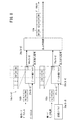
図2は、各ノード14a〜14d内部の概略構成を図示したブロック図である。図2では、各ノード14a〜14dにおいて、通信機能を担うネットワークコントローラ18a〜18dの構成を具体的に図示して説明する。また、各ノード14a〜14dは、略同じ構成である。なお、図2以降において、太い矢印線と細い矢印線とが図示されている場合、太い矢印線は、データの流れを示し、細い矢印線は、制御信号の流れを示す。
[Schematic configuration of each
FIG. 2 is a block diagram illustrating a schematic configuration inside each of the
各ノード14a〜14dのネットワークコントローラ18a〜18dは、それぞれ、データ中継ブロック20a〜20d、データ送信ブロック22a〜22d、データ受信部としてのデータ受信ブロック24a〜24d、出力切替部26a〜26d、及び、メモリとしてのバッファ28a〜28dを有する。
The
図2において、CPU16a〜16dは、図示しないメモリに格納されたプログラムである送信ソフトウェア30a〜30d及び受信ソフトウェア32a〜32dを読み出して実行することにより、ネットワークコントローラ18a〜18dでの送信データの送信処理及び受信データの受信処理を実行させることができる。また、データ中継ブロック20a〜20dとデータ送信ブロック22a〜22dとによって、データの送出機能を担うデータ送出部33a〜33dが構成される。
In FIG. 2,
ここで、ネットワークコントローラ18a〜18dの各部は、概略下記のように機能する。
Here, each part of
データ中継ブロック20a〜20dは、ネットワーク12における上流側(前段)の他ノードから送信された送信データを中継データとして中継し、出力切替部26a〜26dに出力する。なお、前段の他ノードから送信された送信データは、データ中継ブロック20a〜20d、データ送信ブロック22a〜22d及びデータ受信ブロック24a〜24dにそれぞれ受信される。
The data relay blocks 20a to 20d relay transmission data transmitted from other nodes on the upstream side (previous stage) in the
送信ソフトウェア30a〜30dは、自ノードが送信すべきデータである送信データをバッファ28a〜28dに書き込むと共に、バッファ28a〜28d内の所定のアドレスに送信データを書き込んだことを示す送信データ情報をデータ送信ブロック22a〜22dに出力する。データ送信ブロック22a〜22dは、入力された送信データ情報に基づき、該当する送信データをバッファ28a〜28dから読み出し、読み出した送信データを出力切替部26a〜26dに出力する。なお、送信データは、例えば、上述したロボットであれば、主制御ユニットから副制御ユニット宛に送信する制御データや、デバイスとしての各種センサの検出結果をいう。
The
出力切替部26a〜26dは、データの出力待ちを指示する出力待ち信号をデータ中継ブロック20a〜20d又はデータ送信ブロック22a〜22dに出力する。これにより、データ中継ブロック20a〜20d又はデータ送信ブロック22a〜22dのうち、出力待ち信号を受け取った一方のブロックは、出力切替部26a〜26dへのデータ出力を停止すると共に、出力待ち信号を受け取っていない他方のブロックは、出力切替部26a〜26dへのデータ出力を実行する。
The
つまり、出力切替部26a〜26dは、データ中継ブロック20a〜20d又はデータ送信ブロック22a〜22dに出力待ち信号を出力することにより、データを出力するブロックを切り替える。そのため、出力切替部26a〜26dは、送信データ又は中継データの入力を切り替えることにより、いずれか一方のブロックから入力されたデータを出力データとして、ネットワーク12の下流側(後段)の他ノードに送信する。
That is, the
データ受信ブロック24a〜24dは、前段の他ノードから送信された送信データが、自ノード宛のデータである場合、この送信データを受信データとして受信し、当該受信データをバッファ28a〜28dに書き込む。また、データ受信ブロック24a〜24dは、受信データをバッファ28a〜28d内の所定のアドレスに書き込んだことを示す受信データ情報を受信ソフトウェア32a〜32dに通知する。
When the transmission data transmitted from the other node in the previous stage is data addressed to the own node, the data reception blocks 24a to 24d receive the transmission data as reception data and write the reception data in the
受信ソフトウェア32a〜32dは、通知された受信データ情報に基づき、該当する受信データをバッファ28a〜28dから読み出す。これにより、例えば、上述のロボットにおいて、自ノードが副制御ユニットであれば、CPU16a〜16dは、受信データである主制御ユニットからの制御データに基づき、制御対象を駆動制御することができる。また、自ノードが主制御ユニットであれば、CPU16a〜16dは、受信データである副制御ユニットからのセンサの検出結果に基づき、副制御ユニットに対する新たな制御データを生成することが可能となる。
The
なお、各ノード14a〜14dにおいて、ネットワークコントローラ18a〜18dでは、空き時間をできる限り削減して、低レイテンシのデータ通信を実現するため、オンザフライ方式により、中継データを流しながら、当該中継データに対して所定の処理を実行する。なお、送信データ及び受信データについても、オンザフライ方式により、データを流しながら、当該データに対して所定の処理を実行してもよい。
In each of the
次に、データ中継ブロック20a〜20d、データ送信ブロック22a〜22d、データ受信ブロック24a〜24d及び出力切替部26a〜26dの詳細な構成について、図3〜図6を参照しながら説明する。
Next, detailed configurations of the data relay blocks 20a to 20d, the
[データ中継ブロック20a〜20dの構成]
データ中継ブロック20a〜20dは、図3に示すように、パケット判定部(エラー検出部)34a〜34d、制御部36a〜36d、データセレクタ38a〜38d及びデータ保持部(中継データ保持部)40a〜40dを有する。
[Configuration of
As shown in FIG. 3, the data relay blocks 20a to 20d include packet determination units (error detection units) 34a to 34d,
パケット判定部34a〜34dは、前段の他ノードから受信した送信データであるパケット100(図7参照)に対して所定の判定処理を実行する。
The
ここで、パケット100の構造について、図7を参照しながら説明する。なお、本実施形態において、送信データ、中継データ及び受信データは、いずれも、パケット100の構造を有する。
Here, the structure of the
パケット100は、ヘッダ部、データ部、トレーラ部及びCRC部の順に構成されるパケットデータである。
The
ヘッダ部は、所定の符号が格納される「符号」、パケット100の先頭を示す「SOP」、中継数であるホップカウントが格納される「HOP」、及び、送信元のノード14a〜14dのID情報が格納される「SID」から構成される。データ部には、制御データやセンサの検出結果等の所定のデータが格納される。トレーラ部は、パケット100の末尾を示す「EOP」、バッファ28a〜28dの空きバッファサイズ(空き容量情報)が格納される「FBC」、送信先のノード14a〜14dのID情報が格納される「DID」、及び、当該パケット100の優先度を示す「PRI」から構成される。CRC部には、巡回冗長検査に用いられるCRC値が格納される。
The header part includes a “code” in which a predetermined code is stored, “SOP” indicating the head of the
従って、ネットワーク12では、パケット100が送信データ又は中継データとして図1の矢印方向に送信される。
Therefore, in the
図3に戻り、パケット判定部34a〜34dは、オンザフライ方式により、中継データであるパケット100がデータ中継ブロック20a〜20d内を流れている場合に、当該パケット100を構成するCRC部に格納されたCRC値が異常値であるか否かを判定し、その判定結果を制御部36a〜36dに出力する。
Returning to FIG. 3, when the
また、パケット判定部34a〜34dは、パケット100の「SID」に格納された送信元のID情報と、自ノードのID情報とを比較し、両者が一致すれば、当該パケット100が、自ノードから送出され、ネットワーク12を一周して自ノードに戻ってきた送信データであると判定する。パケット判定部34a〜34dは、この判定結果も制御部36a〜36dに出力する。
The
制御部36a〜36dは、パケット判定部34a〜34dの判定結果を受けて、出力データ選択信号をデータセレクタ38a〜38dに供給することで、当該データセレクタ38a〜38dからデータ保持部40a〜40dへのデータ出力を制御する。
The
具体的に、パケット判定部34a〜34dの判定結果が、正常なパケット100であることを示す判定結果、又は、自ノード宛のパケット100ではないことを示す判定結果である場合、制御部36a〜36dは、当該パケット100のデータ保持部40a〜40dへの出力を指示する出力データ選択信号をデータセレクタ38a〜38dに供給する。データセレクタ38a〜38dは、当該出力データ選択信号の供給を受けて、パケット100をデータ保持部40a〜40dに出力する。
Specifically, when the determination results of the
また、パケット判定部34a〜34dの判定結果が、異常なパケット100であることを示す判定結果である場合、制御部36a〜36dは、当該パケット100が異常データであるときのデータ出力を指示する出力データ選択信号をデータセレクタ38a〜38dに供給する。データセレクタ38a〜38dは、当該出力データ選択信号の供給を受けて、パケット100の出力処理を途中で打ち切る。次に、データセレクタ38a〜38dは、打ち切ったパケット100に続けて、当該パケット100が異常データであることを示すエラー表示データ(エラーデータ)44a〜44dを付加し、データ保持部40a〜40dに出力する。その後、データセレクタ38a〜38dは、打ち切ったパケット100の後にデータがないことを示すアイドルデータ42a〜42dをデータ保持部40a〜40dに出力する。
When the determination results of the
つまり、異常なパケット100に応じた出力データ選択信号が供給された場合、データセレクタ38a〜38dは、出力処理が途中で打ち切られた当該パケット100、エラー表示データ44a〜44d及びアイドルデータ42a〜42dの順にデータ保持部40a〜40dに出力する。この場合、他ノードから正常なパケット100(次のデータ)がデータ中継ブロック20a〜20dに入力され、データ保持部40a〜40dに対する当該正常なパケット100の出力を指示する出力データ選択信号が制御部36a〜36dからデータセレクタ38a〜38dに供給されるまで、データセレクタ38a〜38dは、アイドルデータ42a〜42dをデータ保持部40a〜40dに出力し続ける。
That is, when the output data selection signal corresponding to the
また、パケット判定部34a〜34dの判定結果が、自ノードから送信されたパケット100であることを示す判定結果である場合、制御部36a〜36dは、当該パケット100の破棄を指示する出力データ選択信号をデータセレクタ38a〜38dに供給する。データセレクタ38a〜38dは、当該出力データ選択信号の供給を受けて、当該パケット100を破棄する。
When the determination results of the
データ保持部40a〜40dは、FIFO方式のバッファ46a〜46dを有する。従って、データ保持部40a〜40dは、データセレクタ38a〜38dから順次入力されるデータ(パケット100、エラー表示データ44a〜44d、アイドルデータ42a〜42d)を、FIFO方式により、バッファ46a〜46dに一時的に保持した後、中継データとして出力切替部26a〜26d(図2参照)に出力可能である。
The
ここで、出力切替部26a〜26dから制御部36a〜36dに出力待ち信号が入力されている場合、制御部36a〜36dは、データ保持部40a〜40dからの中継データの出力を停止させる。これにより、データセレクタ38a〜38dからデータ保持部40a〜40dに出力されたデータは、バッファ46a〜46dに一時的に保持される。
Here, when an output waiting signal is input from the
一方、出力切替部26a〜26dからの出力待ち信号の入力がない場合、制御部36a〜36dは、データ保持部40a〜40dを制御し、バッファ46a〜46dに一時的に保持されているデータについて、当該バッファ46a〜46dの先頭位置から中継データとして出力切替部26a〜26dに順次出力させる。
On the other hand, when there is no input waiting signal from the
また、データ保持部40a〜40dから出力切替部26a〜26dに出力される中継データがパケット100である場合、制御部36a〜36dは、データセレクタ38a〜38dからデータ保持部40a〜40dにパケット100を出力する際、又は、データ保持部40a〜40dのバッファ46a〜46dでパケット100が一時的に保持される際、パケット100中の「HOP」のホップカウントを+1だけインクリメントする。
When the relay data output from the
[データ送信ブロック22a〜22dの構成]
データ送信ブロック22a〜22dは、図4に示すように、送信完了判定部50a〜50d、制御部52a〜52d、パケット生成部54a〜54d、データ保持部56a〜56d、データセレクタ58a〜58d及び送信データ情報格納バッファ60a〜60dを有する。
[Configuration of
As shown in FIG. 4, the
送信完了判定部50a〜50dは、前段の他ノードから受信した送信データであるパケット100中、「SID」に格納されたID情報と、自ノードのID情報とを比較することにより、当該パケット100が、自ノードのデータ送信ブロック22a〜22dから送信され、ネットワーク12を一周して自ノードに戻ってきた送信データであるか否かを判定する。送信完了判定部50a〜50dは、その判定結果を制御部52a〜52dに出力する。
The transmission
送信ソフトウェア30a〜30dは、送信データ情報を送信データ情報格納バッファ60a〜60dに書き込む。送信データ情報格納バッファ60a〜60dは、送信データの優先度に応じた複数のバッファ62a〜62d、64a〜64d、66a〜66d、68a〜68dから構成される。ここで、優先度とは、データ送信ブロック22a〜22dから送信データとして送出されるデータの優先度をいい、優先度の高いデータである程、他のデータに優先して送出される。従って、送信ソフトウェア30a〜30dは、バッファ28a〜28dに書き込むデータの優先度を予め設定し、設定した優先度に応じて、所望のバッファ62a〜62d、64a〜64d、66a〜66d、68a〜68dに送信データ情報を書き込む。
The
制御部52a〜52dは、各バッファ62a〜62d、64a〜64d、66a〜66d、68a〜68dに送信データ情報が格納されているか否かを確認し、格納されている送信データ情報のうち、優先度の高い情報から順に取り出す。次に、制御部52a〜52dは、取り出した送信データ情報に対応するデータがバッファ28a〜28dに書き込まれているか否かを判定し、該当するデータがあれば、当該データを用いたパケット100の生成を指示するパケット生成指令をパケット生成部54a〜54dに出力する。この場合、制御部52a〜52dは、送信データ情報をパケット生成指令に含めてパケット生成部54a〜54dに出力すればよい。
The
さらに、送信完了判定部50a〜50dでの判定結果が、他ノードから送信されてきた送信データが、自ノードから送信され、ネットワーク12を一周して自ノードに戻ってきたパケット100であるとの判定結果である場合、制御部52a〜52dは、送信データ(次のパケット100)の出力を許可する出力データ選択信号を、データセレクタ58a〜58dに供給する。
Furthermore, the determination result in the transmission
一方、送信完了判定部50a〜50dでの判定結果が、他ノードから送信されてきた送信データが、自ノード以外を送信元とするパケット100であるとの判定結果である場合、制御部52a〜52dは、次のパケット100の出力を禁止し、アイドルデータ72a〜72dの出力を指示する出力データ選択信号を、データセレクタ58a〜58dに供給する。
On the other hand, when the determination result in the transmission
パケット生成部54a〜54dは、制御部52a〜52dからのパケット生成指令に基づき、当該パケット生成指令に応じたデータをバッファ28a〜28dから読み出す。また、パケット生成部54a〜54dは、バッファ28a〜28dの空きバッファサイズも併せて確認する。
The
そして、パケット生成部54a〜54dは、ホップカウントであるHOPを0に設定し、自ノードのID情報をSIDに設定し、読み出したデータをデータ部に格納し、空きバッファサイズをFBCに格納し、送信相手先のID情報をDIDに格納し、当該データの優先度をPRIに格納することにより、図7のパケット100を生成する。生成したパケット100は、ヘッダ部から順にデータ保持部56a〜56dに出力される。
Then, the
データ保持部56a〜56dは、FIFO方式のバッファ70a〜70dを有し、ヘッダ部から順に入力されたパケット100は、FIFO方式でバッファ70a〜70dに一時的に保持される。出力切替部26a〜26d(図2参照)からデータ保持部56a〜56dに出力待ち信号が入力されている場合、データ保持部56a〜56dは、バッファ70a〜70dに一時的に保持されたパケット100の出力を行わない。一方、出力待ち信号の入力がない場合、データ保持部56a〜56dは、バッファ70a〜70dに一時的に保持されているパケット100を、当該バッファ70a〜70dの先頭位置(ヘッダ部)から順にデータセレクタ58a〜58dに出力させる。
The
データセレクタ58a〜58dは、パケット100の出力を指示する出力データ選択信号が制御部52a〜52dから供給されている場合には、データ保持部56a〜56dからのパケット100を送信データとして出力切替部26a〜26dに出力する。また、データセレクタ58a〜58dは、アイドルデータ72a〜72dの出力を指示する出力データ選択信号が制御部52a〜52dから供給されている場合には、アイドルデータ72a〜72dを出力切替部26a〜26dに出力する。
The
従って、送信完了判定部50a〜50dにおいて、自ノードから送信されたパケット100がネットワーク12を一周して自ノードに戻ってきた場合、データ送信ブロック22a〜22d内では、当該パケット100の送信が完了したものと判定し、出力待ち信号の入力がないときに、次のパケット100をデータセレクタ58a〜58dから出力切替部26a〜26dに出力することができる。
Therefore, in the transmission
一方、自ノードから送信されたパケット100の送信が完了していない場合、データ送信ブロック22a〜22d内では、次のパケット100の出力切替部26a〜26dへの送出を禁止し、出力待ち信号の入力がないときに、アイドルデータ72a〜72dをデータセレクタ58a〜58dから出力切替部26a〜26dに出力する。
On the other hand, if the transmission of the
[データ受信ブロック24a〜24dの構成]
データ受信ブロック24a〜24dは、図5に示すように、受信判定部74a〜74d、制御部76a〜76d、データ書き込み部78a〜78d及び受信データ情報格納バッファ80a〜80dを有する。
[Configuration of
As shown in FIG. 5, the data reception blocks 24a to 24d include
受信判定部74a〜74dは、前段の他ノードから送信されてきた送信データのパケット100中、DIDに格納されている送信先のID情報が自ノードのID情報と一致するか否か、すなわち、自ノード宛のパケット100であるか否かを判定し、その判定結果を制御部76a〜76d及びデータ書き込み部78a〜78dに出力する。
The
制御部76a〜76dは、自ノード宛のパケット100であることを示す判定結果の場合、当該パケット100を受信データとして受信すべきことを決定する。次に、制御部76a〜76dは、バッファ28a〜28d内において、当該パケット100を書き込み可能な空きバッファ領域を取得する。そして、制御部76a〜76dは、取得した空きバッファ領域のアドレスに対するパケット100の書き込みを指示するバッファ書き込み先指令をデータ書き込み部78a〜78dに出力すると共に、書き込み先のアドレスを含む当該パケット100に関する受信データ情報を受信データ情報格納バッファ80a〜80dに書き込む。
In the case of a determination result indicating that the packet is addressed to its own node, the
データ書き込み部78a〜78dは、自ノード宛のパケット100であることを示す判定結果と、制御部76a〜76dからのバッファ書き込み先指令とに基づき、当該パケット100を受信データとして、バッファ書き込み先指令で指示されたアドレスに書き込む。
Based on the determination result indicating that the packet is addressed to its
受信データ情報格納バッファ80a〜80dは、受信データの優先度に応じた複数のバッファ82a〜82d、84a〜84d、86a〜86d、88a〜88dから構成される。優先度とは、パケット100のPRIに格納された当該パケット100の優先度をいう。従って、パケット100は、PRIに格納された優先度に対応するバッファ82a〜82d、84a〜84d、86a〜86d、88a〜88dに格納される。
The reception data
この結果、受信ソフトウェア32a〜32dは、各バッファ82a〜82d、84a〜84d、86a〜86d、88a〜88dに受信データ情報が格納されているか否かを確認し、格納されている受信データ情報のうち、優先度の高い情報から順に取り出す。次に、受信ソフトウェア32a〜32dは、取り出した受信データ情報に対応する受信データをバッファ28a〜28dから読み出す。
As a result, the
[出力切替部26a〜26dの構成]
出力切替部26a〜26dは、図6に示すように、制御部90a〜90d及びデータセレクタ92a〜92dを有する。
[Configuration of
As illustrated in FIG. 6, the
制御部90a〜90dは、データ中継ブロック20a〜20d(図2及び図3参照)又はデータ送信ブロック22a〜22d(図2及び図4参照)に出力待ち信号を供給することにより、出力待ち信号を供給した一方のブロックからのデータの入力を阻止すると共に、出力待ち信号を供給しなかった他方のブロックからのデータの入力を許可する。また、制御部90a〜90dは、出力データ選択信号をデータセレクタ92a〜92dに供給することにより、出力待ち信号を供給しなかった他方のブロックから入力されたデータを、出力データとしてデータセレクタ92a〜92dからネットワーク12に送出させる。
The
すなわち、制御部90a〜90dは、中継データ又は送信データの2つの入力データを切り替え、データセレクタ92a〜92dから出力データとしてネットワーク12に送信する。この場合、制御部90a〜90dは、中継データよりも送信データを優先的にデータセレクタ92a〜92dから送出するように、出力待ち信号及び出力データ選択信号を供給する。また、データセレクタ92a〜92dにおいて、一方のデータの出力中、他方のデータとの衝突が発生しないように、制御部90a〜90dは、当該一方のデータである1つのパケット100の出力が完了するまで、他方のデータが出力されないように、当該他方のデータを出力するブロックに対して出力待ち信号を供給する。
That is, the
[本実施形態の5つの特徴的機能]
本実施形態に係る通信システム10は、概略以上のように構成される。次に、本実施形態の特徴的な機能(第1〜第5の特徴的機能)について、図8〜図14Bを参照しながら説明する。ここでは、必要に応じて、図1〜図7も参照しながら説明する。また、図8〜図14Bでは、説明の便宜上、図1〜図7で説明した構成要素の一部を省略し、簡略化して図示する場合がある。
[Five characteristic functions of this embodiment]
The
[第1の特徴的機能]
第1の特徴的機能を説明する前に、従来技術の問題点について説明する。
[First characteristic function]
Prior to describing the first characteristic function, problems of the prior art will be described.
従来、リング型のネットワークにおいて、複数のノードが同時にデータの送信を行うと、データ衝突が発生する。そのため、従来は、特許文献1の技術のように、送信権(フリートークン)を取得したノードのみがデータの送信を行うようにしている。しかしながら、送信すべきデータのサイズが大きくなる程、送信権を持たないノードを有するネットワークでは、ネットワーク効率が低下するという問題がある。なお、一般的に、イーサネット(登録商標)(CSMA/CD)では、バックオフアルゴリズムにより、データ衝突が発生する毎に、待ち時間が長くなってしまい、リアルタイムでの通信制御が困難である。
Conventionally, when a plurality of nodes transmit data at the same time in a ring network, a data collision occurs. Therefore, conventionally, only the node that acquired the transmission right (free token) transmits data as in the technique of
第1の特徴的機能は、上記の問題点を解決するため、中継データと送信データとが同時に出力切替部26a〜26dに入力される可能性がある場合に、これらのデータの衝突を回避するため、出力切替部26a〜26dにおいて、中継データ又は送信データを切り替え、一方のデータを出力データとしてネットワーク12に送信するものである。
In order to solve the above-described problem, the first characteristic function avoids collision of data when relay data and transmission data may be input to the
具体的には、図8に示すように、前段の他ノードからパケット102bが自ノードのデータ中継ブロック20a〜20dに入力され、バッファ46a〜46dに一時的に保持され、一方で、自ノードの送信データであるパケット102cがデータ送信ブロック22a〜22dのバッファ70a〜70dに一時的に保持されているとする。
Specifically, as shown in FIG. 8, the
図8では、中継データであるB0〜B2のパケット102bが順にデータ中継ブロック20a〜20dに入力され、FIFO方式のバッファ46a〜46dに順次格納される。一方、送信データであるC0〜C2のパケット102cは、データ送信ブロック22a〜22dに順に入力され、FIFO方式のバッファ70a〜70dに順次格納される。
In FIG. 8, the relay data B0 to
この場合、B0のパケット102bが、C0のパケット102cよりも時間的に早くバッファ46a〜46dに格納されている。また、B1のパケット102bとC0のパケット102cとは略同時刻にバッファ46a〜46d、70a〜70dにそれぞれ格納される。続けて、B2のパケット102bとC1のパケット102cとが略同時刻にバッファ46a〜46d、70a〜70dにそれぞれ格納され、最後に、C2のパケット102cが最も遅い時刻にバッファ70a〜70dに格納される。
In this case, the
そこで、出力切替部26a〜26dは、基本的には、送信データであるパケット102cを優先的に出力させるべく、出力待ち信号をデータ中継ブロック20a〜20d又はデータ送信ブロック22a〜22dに供給する。
Therefore, the
先ず、B0のパケット102bが、他のB1、B2のパケット102bやC0〜C2のパケット102cよりも時間的に早くバッファ46a〜46dに格納されている。すなわち、B0のパケット102bと同時刻にバッファ70a〜70dに格納されている送信データは存在しない。そのため、出力切替部26a〜26dは、送信データを優先的に出力させる必要はなく、B0のパケット102bを出力させても、中継データと送信データとの間でデータ衝突が発生しないと判断する。
First, the
そして、出力切替部26a〜26bは、データ送信ブロック22a〜22dに対して出力待ち信号を供給する。これにより、データ送信ブロック22a〜22dは、出力待ち信号の供給に基づき、送信データの出力を停止する。一方、データ中継ブロック20a〜20dは、出力待ち信号が供給されていないので、バッファ46a〜46dの先頭に格納されているB0のパケット102bを取り出し、出力切替部26a〜26dに出力する。この結果、出力切替部26a〜26dは、B0のパケット102bをネットワーク12に送出する。
Then, the
次に、B0のパケット102bに続くB1、B2のパケット102bと、C0、C1のパケット102cとが、略同時刻にバッファ46a〜46d、70a〜70dにそれぞれ格納されている。また、バッファ70a〜70dには、C0、C1に続いてC2のパケット102cも格納されている。従って、データ中継ブロック20a〜20dから中継データを出力させると共に、データ送信ブロック22a〜22dから送信データを出力させると、データ衝突が発生する可能性がある。
Next, the B1 and
そこで、中継データと送信データとの間でのデータ衝突を回避すると共に、送信データを優先的に出力させるため、出力切替部26a〜26dは、データ中継ブロック20a〜20dに出力待ち信号を供給すると共に、データ送信ブロック22a〜22dに対する出力待ち信号の供給を停止する。これにより、データ中継ブロック20a〜20dは、出力待ち信号の供給を受けて、B1、B2のパケット102bの出力を停止する。一方、データ送信ブロック22a〜22dは、出力待ち信号の供給停止により、バッファ70a〜70dからC0、C1、C2の順にパケット102cを取り出し、出力切替部26a〜26dに順次出力する。この結果、出力切替部26a〜26dは、B0のパケット102bに続いて、C0〜C2のパケット102cをネットワーク12に送出する。
Therefore, in order to avoid data collision between the relay data and the transmission data and to output the transmission data with priority, the
C0〜C2のパケット102cの送出後、出力切替部26a〜26dは、データ中継ブロック20a〜20dへの出力待ち信号の供給を停止すると共に、データ送信ブロック22a〜22dに出力待ち信号を供給する。これにより、データ中継ブロック20a〜20dは、出力待ち信号の供給停止により、バッファ46a〜46dからB1、B2の順にパケット102bを取り出し、出力切替部26a〜26dに順次出力する。一方、データ送信ブロック22a〜22dは、出力待ち信号の供給により、送信データの出力を停止する。この結果、出力切替部26a〜26dは、C0〜C2のパケット102cに続いて、B1、B2のパケット102bをネットワーク12に送出する。
After sending the C0 to
従って、図8に示すノード14a〜14d内での上記の動作により、出力切替部26a〜26dは、データ衝突を発生させることなく、B0、C0、C1、C2、B1、B2の順に送出したパケット104をネットワーク12上で一方向に送信することができる。
Therefore, by the above operation in the
このように、第1の特徴的機能では、中継データと送信データとの切り替えのタイミングを制御すると共に、中継データをデータ保持部40a〜40dのバッファ46a〜46dで一時的に保持するか、又は、送信データをデータ保持部56a〜56dのバッファ70a〜70dで一時的に保持することが可能である。これにより、全てのノード14a〜14dが同時にデータを送信しても、データ衝突を発生させることなく、低レイテンシ且つ高いネットワーク効率のデータ通信が可能となる。
As described above, in the first characteristic function, the switching timing between the relay data and the transmission data is controlled, and the relay data is temporarily held in the
[第2の特徴的機能]
第2の特徴的機能を説明する前に、従来技術の問題点について説明する。
[Second characteristic function]
Prior to describing the second characteristic function, problems of the prior art will be described.
従来、ネットワークを介して送信されてきたパケットについて、当該パケットを受信したノードは、終了コード(図7のEOP)が来ない場合、タイムアウト等の当該パケットの異常を検出したときに、このパケットを破棄したい。 Conventionally, with respect to a packet transmitted via a network, when a node that has received the packet does not receive an end code (EOP in FIG. 7), the node receives this packet when detecting an abnormality of the packet such as a timeout. I want to destroy it.
この場合、低レイテンシを実現するため、オンザフライ方式によりデータを流すときに、前記異常なパケットの一部が後段のブロックに届いていれば、後段のブロックは、当該パケットの異常を早期に検出したので、前記パケットを破棄したい。しかしながら、このパケットが可変長パケットであれば、どこまでが正常なパケットであるのかが分からず、後段のノードは、当該パケットを破棄することができない。 In this case, in order to realize low latency, if a part of the abnormal packet reaches the subsequent block when data is flowed by the on-the-fly method, the subsequent block detects the abnormality of the packet early. So I want to discard the packet. However, if this packet is a variable-length packet, it is not known how far it is a normal packet, and the subsequent node cannot discard the packet.
第2の特徴的機能は、上記の問題を解決するため、オンザフライ方式により中継データを流している場合に、前段のブロックで中継データの異常を検出した後、異常な中継データ、エラー表示データ及びアイドルデータを順に送出し、後段のブロックでエラー表示データを検出して、当該中継データを破棄するものである。すなわち、第2の特徴的機能では、中継データの異常を前段のブロックで検出し、異常を示す検出結果を後段のブロックに伝達することにより、後段のブロックにおいて、異常な中継データを早期に破棄する。 In order to solve the above-described problem, the second characteristic function is to detect abnormal relay data, error display data, and error data after detecting relay data abnormality in the preceding block when relay data is being flowed on-the-fly. Idle data is sent in order, error display data is detected in the subsequent block, and the relay data is discarded. In other words, in the second characteristic function, relay data abnormalities are detected in the preceding block, and the detection result indicating the abnormality is transmitted to the succeeding block, so that abnormal relay data is discarded early in the succeeding block. To do.
ここでは、一例として、図9に示すように、前段のブロックがノード14bのデータ中継ブロック20bであり、後段のブロックがノード14cのデータ中継ブロック20cである場合について説明する。
Here, as an example, as shown in FIG. 9, a case will be described in which the preceding block is the
中継データであるパケット120がノード14bに入力された場合、ノード14bのパケット判定部34bは、オンザフライ方式により流れているパケット120中のCRC値をチェックし、異常値(異常データ)であるか否かを判定する。なお、パケット120は、図7のパケット100と同じパケット構造を有しているが、図9では、説明の便宜上、簡略化して図示している。
When the
CRC値が異常データであると判定した場合、パケット判定部34bは、その判定結果を制御部36b(図3参照)に出力し、制御部36bは、エラー表示データ44b及びアイドルデータ42bの出力を指示する出力データ選択信号をデータセレクタ38bに供給する。
When it is determined that the CRC value is abnormal data, the
データセレクタ38bは、供給された出力データ選択信号に基づき、パケット120の出力処理を直ちに打ち切り、打ち切ったパケット120に続けて、エラー表示データ44b及びアイドルデータ42bを順に出力する。この結果、データ中継ブロック20bからは、出力処理が途中で打ち切られたパケット120、エラー表示データ44b及びアイドルデータ42bを含む新たなパケット122が出力される。このパケット122は、出力切替部26bからネットワーク12を介して後段のノード14cに送出される。なお、前述のように、パケット120の出力が途中で打ち切られるので、新たなパケット122中、パケット120に相当するデータ長は、パケット120のデータ長よりも短くなる。
The
ノード14cにパケット122が入力された場合、ノード14cのパケット判定部34cは、オンザフライ方式により流れているパケット122をチェックする。この結果、エラー表示データ44bを見つけた場合、パケット判定部34cは、当該パケット122が異常データであると判定し、その判定結果を制御部36c(図3参照)に出力する。制御部36cは、パケット122の破棄とアイドルデータ42cの出力とを指示する出力データ選択信号をデータセレクタ38cに供給する。
When the
データセレクタ38cは、供給された出力データ選択信号に基づき、パケット122を破棄すると共に、アイドルデータ42cを出力する。この結果、データ中継ブロック20cからは、アイドルデータ42cであるパケット126が出力される。このパケット126は、出力切替部26cからネットワーク12を介して後段のノード14dに送出される。これにより、異常データ(パケット120、122)がネットワーク12上を巡回することを回避することができる。
The
このように、第2の特徴的機能では、オンザフライ方式で中継データを流しているときに、前段のブロックで当該中継データの異常を検出すると、異常であることを示す検出結果(エラー表示データ44b)を、当該中継データの最後に付加して後段のブロックに伝達するので、後段のブロックでは、エラー表示データ44bに基づき、中継データを早期に破棄することができる。これにより、異常なパケットである中継データがネットワーク12上に流れ続けてしまうことを回避して、次の正常な中継データをできる限り早くネットワーク12上に流すことが可能となる。この結果、ネットワーク効率の低下を最小にすることができる。
As described above, in the second characteristic function, when relay data is flowed in the on-the-fly method, if an abnormality in the relay data is detected in the preceding block, a detection result (
なお、上記の説明では、ノード14bでパケット120に対する異常データの検出を行い、ノード14cで異常データを含むパケット122を破棄する場合について説明した。第2の特徴的機能では、上記の説明に限定されることはなく、少なくとも、ネットワーク12における前段のブロックでパケット120に対する異常データの検出処理を行い、後段のブロックで異常データを含むパケット122を破棄できればよい。
In the above description, the case where the abnormal data for the
従って、第2の特徴的機能では、1つのノード14a〜14d内において、前段のデータ中継ブロック20a〜20dのパケット判定部34a〜34dが、パケット120に対する異常データの検出処理(判定処理)を行い、後段の出力切替部26a〜26dの制御部90a〜90dが、異常データとしてのパケット122を検出し、データセレクタ92a〜92dが当該パケット122を破棄することも可能である。
Accordingly, in the second characteristic function, the
また、第2の特徴的機能では、上述のように、2つのノード14a〜14dにまたがって、パケット120に対する異常データの検出処理と、パケット122の検出及び破棄とを行うことができる。これにより、例えば、前段のノード14a〜14dを構成する出力切替部26a〜26dの制御部90a〜90dが、パケット120に対する異常データの検出処理を行い、後段のノード14a〜14dを構成するデータ中継ブロック20a〜20dのパケット判定部34a〜34dが、異常データとしてのパケット122を検出することも可能である。この場合、当該データ中継ブロック20a〜20dのデータセレクタ38a〜38dがパケット122を破棄することになる。
In the second characteristic function, as described above, the abnormal data detection process for the
[第3の特徴的機能]
第3の特徴的機能を説明する前に、従来例について、図10Aを参照しながら説明する。図10Aの従来例において、本実施形態と同じ構成要素については、同じ参照符号を付けて説明する。
[Third characteristic function]
Prior to describing the third characteristic function, a conventional example will be described with reference to FIG. 10A. In the conventional example of FIG. 10A, the same components as those of the present embodiment are described with the same reference numerals.
図10Aに示す従来例の通信システム110において、ノード14aは、送信先のノード14dに向けてパケット112を送出する。送出されたパケット112は、ネットワーク12上、ノード14b、14cを介してノード14dに送信される。ノード14dは、受信したパケット112の正当性を確認した後、当該パケット112に対する肯定応答(ACK)114を、ネットワーク12を介して、送信元のノード14aに向けて送出する。ノード14aは、ACK114を受信することにより、送信先のノード14dがパケット112を受信したことを把握し、パケット112の送信が完了したと判断する。
In the
しかしながら、従来の通信システム110では、送信先のノード14dによるパケット112の受信を保証することは可能であるが、一方で、ノード14dがパケット112の正当性を確認し、確認が取れればパケット112に対するACK114をノード14aに送信するため、レイテンシが増大するという問題があった。
However, in the
第3の特徴的機能は、このような問題を解決するため、自ノードから送出した送信データをネットワーク12で一巡させ、当該送信データが自ノードに戻ってきたときに、送信データの送信を完了させることにより、ネットワーク12に異常がないことを保証しつつ、低レイテンシのデータ通信を実現するものである。この場合、ネットワーク12上の他ノードは、自身が送信データを受信するか否かに関わりなく、当該送信データを中継する。従って、自ノードから送出された送信データは、ネットワーク12に断線等の故障がなければ、ネットワーク12を一周して自ノードに戻ってくることができる。
In order to solve such a problem, the third characteristic function makes a round of transmission data transmitted from the own node through the
ここでは、一例として、図10Bに示すように、自ノードがノード14aであり、ノード14aから他ノードであるノード14dに向けて、送信データであるパケット116を送出する場合について説明する。
Here, as an example, as shown in FIG. 10B, a case will be described in which the own node is the
第3の特徴的機能において、データ送信ブロック22a(図2及び図4参照)は、送信完了判定部50aを有している。自ノードであるノード14aからノード14dに向けてパケット116を送信した場合、当該パケット116は、ノード14b〜14dで中継されながら、ネットワーク12を一周し、ノード14aに戻ってくる。受信したパケット116がノード14aから送信した送信データであると送信完了判定部50aが判定すれば、制御部52aは、当該パケット116の送信を完了させ、パケット116を破棄することができる。
In the third characteristic function, the
なお、送信先のノード14dでは、データ中継ブロック20d及び出力切替部26d(図2参照)がパケット116を中継データとして中継すると共に、データ受信ブロック24dがパケット116を受信データとして受信する。
In the
具体的に、パケット116は、図7のパケット100と同様のパケット構造を有する。この場合、ノード14aのパケット生成部54a(図4参照)は、ヘッダ部のSIDにノード14aのID情報を埋め込むと共に、トレーラ部のDIDに送信先のノード14dのID情報を埋め込むことによりパケット116を生成する。これにより、ノード14aがパケット116を送信すれば、送信完了判定部50aは、ネットワーク12を一周して受信されたパケット116中、SIDに埋め込まれたID情報と、ノード14aのID情報とが一致すれば、ネットワーク12に断線等の故障が発生しておらず、パケット116の送信が完了したことを容易に判定することができる。
Specifically, the
上記の説明では、自ノードがノード14aであり、送信先がノード14dである場合について説明したが、第3の特徴的機能では、自ノードがノード14b〜14dである場合にも適用可能であることは勿論である。また、送信先のノード14dがパケット116を受信しているか否かの保証は、例えば、送信ソフトウェア30a及び受信ソフトウェア32a側で所定の処理を行うことによって保証すればよい。
In the above description, the case where the own node is the
[第4の特徴的機能]
第4の特徴的機能を説明する前に、従来技術の問題点について説明する。
[Fourth characteristic function]
Prior to describing the fourth characteristic function, problems of the prior art will be described.
従来、送信先のノードにデータを送信する場合、下記の問題によって、レイテンシが増加し、データを確実に送信先のノードに送信できなかった。すなわち、送信先のノード内のバッファの状況(空き容量)を問い合わせることなくデータを送信すると、送信先のノードにおいて、バッファにデータを格納しようとしても、データを格納できず、破棄せざるを得ない場合がある。また、送信先のノード内のバッファの状況を問い合わせる場合、送信元のノードと送信先のノードとの間で、問い合わせ状況を確認するためのデータ通信が必要となり、レイテンシが増大する。この結果、リアルタイムでの通信制御が困難となる。 Conventionally, when data is transmitted to a transmission destination node, the latency increases due to the following problems, and data cannot be transmitted to the transmission destination node reliably. That is, if data is transmitted without inquiring about the status (free space) of the buffer in the destination node, even if the destination node attempts to store data in the buffer, the data cannot be stored and must be discarded. There may not be. Further, when inquiring about the status of the buffer in the transmission destination node, data communication for confirming the inquiry status is required between the transmission source node and the transmission destination node, which increases latency. As a result, real-time communication control becomes difficult.
第4の特徴的機能は、上記の問題点を解決するため、図11A及び図11Bに示すように、自ノードのバッファ28b〜28dの空きバッファサイズを含む送信データを、ネットワーク12を介して他ノードに送信することにより、当該バッファ28b〜28dで格納可能なデータ量を他ノードに通知するというものである。
In order to solve the above-described problem, the fourth characteristic function is to transmit transmission data including free buffer sizes of its
具体的に、図11Aにおいて模式的に示すように、ノード14bのバッファ28bの空きバッファサイズが6(60%の空き容量)、ノード14cのバッファ28cの空きバッファサイズが2(20%の空き容量)、ノード14dのバッファ28dの空きバッファサイズが8(80%の空き容量)であったとする。
Specifically, as schematically shown in FIG. 11A, the free buffer size of the
各ノード14b〜14dのデータ送信ブロック22b〜22d(図2及び図4参照)を構成するパケット生成部54b〜54dは、それぞれ、バッファ28b〜28dの空きバッファサイズを確認し、トレーラ部のFBCに空きバッファサイズを格納したパケット100(図7参照)を生成する。そして、各ノード14b〜14dは、それぞれ、ネットワーク12を介して他ノードにパケット100を送信する。
The packet generators 54b to 54d constituting the data transmission blocks 22b to 22d (see FIG. 2 and FIG. 4) of the
これにより、例えば、ノード14aのデータ受信ブロック24a(図2及び図5参照)において、データ書き込み部78aは、各ノード14b〜14dからパケット100を受信する毎に、当該パケット100に含まれる空きバッファサイズを、バッファ28a内に設けた空き容量情報レジスタ130aに書き込むことができる。図11Bは、空き容量情報レジスタ130aに格納された各ノード14a〜14dの空きバッファサイズを図示したものである。空き容量情報レジスタ130aでは、送信元のID情報(SID)に対応付けて空きバッファサイズ(FBC)が格納される。
Thus, for example, in the
また、第4の特徴的機能において、各ノード14b〜14dは、一定間隔毎に、自ノードのID情報及び空きバッファサイズを含むパケット100を生成し、ネットワーク12を介して他ノードに当該パケット100を送信する。従って、ノード14aのデータ書き込み部78aは、パケット100を受信する毎に、当該パケット100に含まれる送信元のID情報と空きバッファサイズとを空き容量情報レジスタ130aに書き込む。これにより、空き容量情報レジスタ130a内の空きバッファサイズを、最新の情報に更新することができる。
Further, in the fourth characteristic function, each of the
このように、第4の特徴的機能では、各ノード14a〜14dのバッファ28a〜28dの空きバッファサイズが一定間隔毎に通知され、最新の情報に更新されるので、送信先のノードにデータを送信する際、送信先のノード内のバッファの状況(空きバッファサイズ)を問い合わせることなく、当該バッファの状況を把握することができる。これにより、低レイテンシでデータを送信先のノードに確実に送信することが可能となる。この結果、送信先のノードにデータを送信する際に、送信先のノードにおける空きバッファサイズが送信すべきデータ量よりも小さい場合には、当該データの送信を後回しにして、当該データ量以上の空きバッファサイズとなったときに送信先のノードにデータを送信するような通信制御も実現可能となる。
In this way, in the fourth characteristic function, the empty buffer sizes of the
なお、上記の説明では、ノード14b〜14dのバッファ28b〜28dの空きバッファサイズを、パケット100の送信によって他ノードに通知する場合について説明した。第4の特徴的機能では、ノード14aのバッファ28aの空きバッファサイズをパケット100の送信によってノード14b〜14dに通知することも可能である。
In the above description, a case has been described in which the empty buffer sizes of the
また、上記の説明では、ノード14aにおいて、他のノード14b〜14dからパケット100を受信する毎に、バッファ28aの空き容量情報レジスタ130aの内容が更新される場合について説明した。他のノード14b〜14dにおいても、バッファ28b〜28dに空き容量情報レジスタ130b〜130dがそれぞれ設けられている。従って、各ノード14b〜14dでも、他ノードからパケット100を受信する毎に、空き容量情報レジスタ130b〜130dに格納された空きバッファサイズを最新の内容に更新することが可能である。
In the above description, the case where the content of the free
[第5の特徴的機能]
第5の特徴的機能を説明する前に、従来技術の問題点について説明する。従来、リング型のネットワーク12では、ネットワーク12の断線やノード14a〜14dの故障が発生すると、当該ネットワーク12上での一方向の通信が不可能となる。しかも、ネットワーク12上、どの箇所で断線等の故障が発生したのかを特定することも困難である。
[Fifth characteristic function]
Prior to describing the fifth characteristic function, problems of the prior art will be described. Conventionally, in the ring-
第5の特徴的機能は、上記の問題を解決するため、図12A〜図14Bに示すように、自ノードのID情報とホップカウントとをパケット100に埋め込んで送信した場合、各ノード14a〜14dで当該パケット100を中継する毎に、パケット100のHOPに格納されたホップカウントが+1だけインクリメントされ、ネットワーク12を一周して当該パケット100が自ノードに戻ってくるようにしている。
In order to solve the above problem, the fifth characteristic function is that each
具体的に、ノード14a〜14dのデータ送信ブロック22a〜22d(図2及び図4参照)を構成するパケット生成部54a〜54dは、それぞれ、自ノードのID情報をSIDに格納し、且つ、HOPのホップカウントを0に設定したパケット100(図7参照)を生成する。そして、各ノード14a〜14dは、ネットワーク12にパケット100を送出する。
Specifically, the
これにより、図12Aに示すように、例えば、ネットワーク12が正常時の場合、ノード14aから送出されたパケット100は、ノード14b〜14dを介して、ネットワーク12を一周し、ノード14aに戻る。この場合、各ノード14b〜14dのデータ中継ブロック20b〜20d(図2及び図3参照)では、制御部36b〜36dが当該パケット100のHOPに格納されたホップカウントを+1だけインクリメントする。すなわち、パケット100は、各ノード14b〜14dを中継される毎に、ホップカウントが+1ずつインクリメントされる。従って、パケット100がネットワーク12を一周することによりノード14aで受信された場合、当該パケット100のHOPに格納されたホップカウントは、3(HOP=3)となる。
Thereby, as illustrated in FIG. 12A, for example, when the
同様にして、各ノード14b〜14dからパケット100がそれぞれ送出され、ネットワーク12を一周して戻ってきた場合、図12Aの構成では、自ノードに戻ってきたパケット100のホップカウントは、それぞれ3となる。
Similarly, when the
つまり、図12Aの正常時の場合、各ノード14a〜14dは、自ノードからパケット100を送出し、ネットワーク12を一周させてパケット100が戻ってきたときに、ホップカウントを確認することで、自ノードから見たときのネットワーク12の中継数、すなわち、ネットワーク12に接続されている他ノードの数を把握することができる。
That is, in the normal state of FIG. 12A, each of the
また、各ノード14a〜14dのデータ中継ブロック20a〜20dは、他ノードから送出されたパケット100を中継する。その際、当該パケット100は、データ受信ブロック24a〜24d(図2及び図5参照)も受信する。従って、データ受信ブロック24a〜24dは、中継データであるパケット100に格納された送信元のID情報(SID)と、ホップカウント(HOP)とを確認することで、自ノードに対する送信元のノードの位置関係や接続状態を把握することができる。
The data relay blocks 20a to 20d of the
そして、データ受信ブロック24a〜24dのデータ書き込み部78a〜78dは、パケット100を受信する毎に、当該パケット100のSIDに格納されたID情報と、HOPに格納されたホップカウントとをバッファ28a〜28dに設けられたホップカウントレジスタ132a〜132dに格納する。
Each time the
図12Bは、ノード14aのバッファ28aに設けられたホップカウントレジスタ132aを図示したものである。この場合、データ書き込み部78aは、パケット100を受信する毎に、当該パケット100に含まれる送信元のID情報(SID)とホップカウント(HOP)とをホップカウントレジスタ132aに書き込み、最新の情報に更新する。従って、ノード14aでは、ホップカウントレジスタ132aを確認することにより、ノード14aに対する他のノード14b〜14dの位置関係や接続状態を容易に把握することができる。
FIG. 12B illustrates the
なお、第5の特徴的機能では、パケット100に時刻データを埋め込んで送信してもよい。これにより、自ノードからパケット100を送信してから一定時間経過しても、パケット100が受信データとして受信されない場合には、ネットワーク12に故障が発生したものと判定することが可能である。
In the fifth characteristic function, the time data may be embedded in the
次に、ネットワーク12において、接続順を誤ってノード14a〜14dを接続した場合について、図13A及び図13Bを参照しながら説明する。この場合、図12Aの正常時と同様に、ノード14aは、自ノードのID情報及びホップカウントを含むパケット100を送信する。この場合、ノード14b〜14dについて、接続ミスが発生しているときでも、ネットワーク12自体に断線等の故障がなければ、各ノード14b〜14dは、パケット100を中継する毎に、ホップカウントを+1だけインクリメントし、インクリメント後のパケット100を送出する。
Next, a case where the
同様にして、各ノード14b〜14dから自ノードで生成したパケット100をそれぞれネットワーク12に送出した場合でも、他ノードでは、当該パケット100を中継する毎に、ホップカウントを+1だけインクリメントした後に、インクリメント後のパケット100を送出する。
Similarly, even when the
図13Bは、図13Aの構成において、ノード14aのバッファ28aに設けられたホップカウントレジスタ132aを図示したものである。この場合、ホップカウントレジスタ132aに、正常時の場合(図12B参照)と、図13Aのような接続ミス時の場合(図13B参照)とに関して、送信元のID情報とホップカウントとを格納しておけば、両者を比較することにより、接続ミスが発生しているか否か、さらには、正常時と比べてどのような接続ミスが発生しているのかを容易に把握することができる。
FIG. 13B illustrates the
次に、ネットワーク12に断線等の故障が発生している場合について、図14A及び図14Bを参照しながら説明する。この場合、図12Aの正常時と同様に、ノード14aは、自ノードのID情報及びホップカウントを含むパケット100を送信する。
Next, a case where a failure such as disconnection occurs in the
例えば、ネットワーク12上、ノード14aとノード14bとの間が断線している場合、断線箇所から先にパケット100を送信することができないため、当該パケット100は、ネットワーク12を一周することができない。従って、ノード14aは、自ノードから送出されたパケット100を受信することができない。
For example, when the
一方、各ノード14b〜14dは、それぞれ、パケット100を生成し、ノード14aに向けて当該パケット100を送出する。この場合、各パケット100の送信方向には断線箇所がないため、各パケット100は、ノード14aにそれぞれ入力される。この場合も、各ノード14c、14dは、パケット100を中継する毎に、ホップカウントを+1だけインクリメントした後に、インクリメント後のパケット100を送出する。
On the other hand, each
図14Bは、図14Aの構成において、ノード14aのバッファ28aに設けられたホップカウントレジスタ132aを図示したものである。この場合も、ホップカウントレジスタ132aに、正常時の場合(図12B参照)と、図14Aのような故障時の場合(図14B参照)とに関して、送信元のID情報とホップカウントとを格納しておけば、両者の結果を比較することにより、故障が発生しているか否か、さらには、正常時と比べてどの箇所に故障が発生しているのかを容易に把握することができる。
FIG. 14B illustrates the
このように、第5の特徴的機能では、ホップカウントを埋め込んだパケット100をネットワーク12に一巡させ、ノード14a〜14dで当該パケット100を中継する毎にホップカウントを+1だけインクリメントするので、ネットワーク12に接続されているノード14a〜14dを常に検出することができ、断線等の故障個所の特定が可能となる。また、ソフトウェアハングが発生したノード14a〜14dが存在する場合には、このノード14a〜14dからパケット100が送信されることはなく、ホップカウントの更新も行われないので、当該ノード14a〜14dが故障していることを検出することが可能である。さらに、故障対象が特定されることで、ネットワーク12上、縮退運転を行う等、通信システム10全体でのフェールソフト動作が可能となる。
As described above, in the fifth characteristic function, the
なお、図12A〜図14Bは、一例として、ノード14aを自ノードとした場合であったが、ノード14b〜14dを自ノードとした場合でも、同様に適用可能であることは勿論である。
12A to 14B show the case where the
[本実施形態の効果]
本実施形態に係る通信システム10において、データ送出部33a〜33dは、自ノードが生成したデータを送信データとして送信するデータ送信ブロック22a〜22d、及び、他ノードから送信された送信データを中継データとして中継するデータ中継ブロック20a〜20dを有する。また、データ受信ブロック24a〜24dは、他ノードから送信された送信データを受信データとして受信する。出力切替部26a〜26dは、データ送信ブロック22a〜22dが送信した送信データ、又は、データ中継ブロック20a〜20dが中継した中継データのうち、いずれか一方のデータを出力データとして切り替え出力する。
[Effect of this embodiment]
In the
通常、リング型のネットワークトポロジーであるネットワーク12において、各ノード14a〜14dは、送信ラインと受信ラインとに分けて構築されている。従って、各ノード14a〜14dの送信ラインは、データの送信に関して占有権をそれぞれ持っていると考えることができる。
Normally, in the
そこで、本実施形態では、ネットワーク12における新たなプロトコルとして、出力切替部26a〜26dにおいて、送信データ又は中継データのうち、いずれか一方のデータを出力データとして、切り替えて出力する。このような新たなプロトコルを構築したことにより、全てのノード14a〜14dでは、送信データと中継データとを衝突させることなく、出力データの送信を同時に行うことが可能となる。従って、本実施形態は、低レイテンシ且つネットワーク効率が向上した通信システム10を実現することができる。この結果、本実施形態では、F/W及びH/Wのデータやログデータ等の大容量データについても、従来と比べて短時間で転送することが可能となる。
Therefore, in the present embodiment, as a new protocol in the
次に、第1〜第5の特徴的機能の効果について説明する。 Next, effects of the first to fifth characteristic functions will be described.
[第1の特徴的機能の効果]
出力切替部26a〜26dは、データ送信ブロック22a〜22dが送信した送信データを出力データとして優先的に出力する。これにより、他ノードからの送信データである中継データと、自ノードの送信データとを衝突させることなく、リアルタイムでデータ通信を行うことが可能となる。この結果、全てのノード14a〜14dが同時にデータ通信を行っても、データ衝突を発生させることなく、高いネットワーク効率でデータ通信を行うことができる。
[Effect of first characteristic function]
The
また、データ中継ブロック20a〜20dは、データ送信ブロック22a〜22dが送信した送信データを出力切替部26a〜26dが優先的に出力する間、中継データを一時的に保持するデータ保持部40a〜40dを有する。これにより、送信データの出力完了後に中継データを出力することになるので、中継データと送信データとの衝突を確実に回避して、ネットワーク効率を向上させることができる。
The data relay blocks 20a to 20d are
さらに、データ送信ブロック22a〜22dが送信した送信データがネットワーク12を一周してデータ送信ブロック22a〜22dに戻ってくるまで、当該データ送信ブロック22a〜22dは、次の送信データの送信を行わない。これにより、中継データの送信時間を確保すると共に、中継データの中継時間を最小化することが可能となる。また、当該中継データと送信データとの衝突を効果的に回避して、ネットワーク効率の向上を図ることもできる。
Further, until the transmission data transmitted by the
さらにまた、出力切替部26a〜26dは、データの出力待ちを指示する出力待ち信号をデータ送信ブロック22a〜22d又はデータ中継ブロック20a〜20dに出力し、データ送信ブロック22a〜22d又はデータ中継ブロック20a〜20dのうち、出力待ち信号の入力されていないブロックが、出力切替部26a〜26dにデータを送出する。これにより、中継データと送信データとの衝突を確実に回避することができる。
Furthermore, the
[第2の特徴的機能の効果]
各ノード14a〜14dのデータ送出部33a〜33d及び出力切替部26a〜26dは、オンザフライ方式によるデータの出力中、当該データの異常を検出可能なエラー検出部(パケット判定部34a〜34d、制御部90a〜90d)を有する。この場合、例えば、パケット判定部34a〜34dがデータの異常を検出したときに、データ送出部33a〜33dは、当該データに異常があることを示すエラー表示データ44a〜44dをデータに付加して出力する。
[Effect of second characteristic function]
The
すなわち、空き時間をできる限り削減して、低レイテンシの通信を実現するために、オンザフライ方式でデータを出力する場合、異常なデータに対してはエラー表示データ44a〜44dを付加して出力する。この結果、後段のブロックは、エラー表示データ44a〜44dを確認することで、入力されたデータが異常なデータであることを容易に把握し、当該異常なデータを早期に破棄することができる。従って、次に送信する正常なデータをできる限り早く送出することができ、ネットワーク効率の低下を最小限に留めることが可能となる。
That is, in order to reduce idle time as much as possible and realize low-latency communication, when data is output on the fly method,
また、データの異常を検出した場合、エラー検出部を有するデータ送出部33a〜33d又は出力切替部26a〜26dは、データの出力を途中で打ち切り、打ち切ったデータの最後にエラー表示データ44a〜44dを付加して出力する。これにより、後段のブロックにおいて、異常なデータを早期に把握して破棄することが可能となり、ネットワーク効率の低下を確実に抑制することができる。
In addition, when data abnormality is detected, the
さらに、後段の出力切替部26a〜26d又はデータ送出部33a〜33dは、打ち切ったデータを受信し、自己のエラー検出部がエラー表示データ44a〜44dを検出したときに、打ち切ったデータを破棄すると共に、アイドルデータ42a〜42dを出力する。これにより、打ち切ったデータがネットワーク12を巡回し続けることを回避することができる。
Further, the
さらにまた、エラー検出部がデータの異常を検出した場合、当該エラー検出部を有するデータ送出部33a〜33d又は出力切替部26a〜26dは、打ち切ったデータ及びエラー表示データ44a〜44dを順に出力した後、次のデータが入力されるまで、アイドルデータ42a〜42dを出力する。これにより、後段のブロックでは、入力されたデータのうち、エラー表示データ44a〜44dの直前までのデータが異常なデータであることを容易に把握することができる。
Furthermore, when the error detection unit detects an abnormality in the data, the
[第3の特徴的機能の効果]
各ノード14a〜14dのデータ送信ブロック22a〜22dは、受信データが自ノードで生成した送信データであるか否かを判定する送信完了判定部50a〜50dを有する。そして、受信データが自ノードで生成した送信データであると送信完了判定部50a〜50dが判定した場合、データ送信ブロック22a〜22dは、当該送信データの送信を完了させる。
[Effect of third characteristic function]
The
従来は、自ノードから送信先のノードに送信データを送信し、送信データを受け取った送信先のノードからのACK114を自ノードが受け取ることにより、送信データの送信が完了していた。この場合、送信先のノードが送信データを受信したことを保証することは可能であるが、一方で、レイテンシが増大するという問題があった。
Conventionally, transmission of transmission data has been completed by transmitting transmission data from the own node to the destination node and receiving the
これに対して、第3の特徴的機能では、データ送信ブロック22a〜22dが送信完了判定部50a〜50dを有することにより、自ノードから送信された送信データがネットワーク12を一周し、自ノードで受信データとして受信されたときに、送信データの送信を完了させることができる。これにより、送信先のノードが送信データを受信したことまでは保証しないが、ネットワーク12に異常がないことを保証すると共に、低レイテンシのデータ通信が可能となる。
On the other hand, in the third characteristic function, since the
また、送信データ及び受信データは、ヘッダ部、データ部及びトレーラ部を含むパケット100であり、ヘッダ部に、自ノードのID情報(SID)が埋め込まれると共に、トレーラ部に送信先のノードのID情報(DID)が埋め込まれる。この場合、送信完了判定部50a〜50dは、ヘッダ部に埋め込まれたID情報が自ノードのID情報と一致すれば、受信データが自ノードで生成した送信データであると判定する。そして、データ送信ブロック22a〜22dは、送信完了判定部50a〜50dの判定結果を受けて、送信データの送信を完了させ、当該送信データを破棄する。
The transmission data and the reception data are a
これにより、送信データの送信完了を効率よく判定できると共に、低レイテンシのパケット通信を行うことが可能となる。 As a result, it is possible to efficiently determine the completion of transmission of transmission data and to perform low-latency packet communication.
[第4の特徴的機能の効果]
各ノード14a〜14dのデータ送信ブロック22a〜22dは、自ノードのID情報とバッファ28a〜28dの空きバッファサイズとを送信データ(パケット100)に埋め込んで送信する。
[Effect of the fourth characteristic function]
The
これにより、送信データを中継データ又は受信データとして受け取った他ノードは、送信元のノード(自ノード)のバッファ28a〜28dにどの程度の空きバッファサイズが存在するのかを容易に把握することができる。これにより、他ノードは、送信元のノードに対してデータを送信する際、空きバッファサイズを考慮したデータ量のデータを送信すればよい。この結果、送信先のノードのバッファ28a〜28dに空き容量がないため、折角送信したデータが当該送信先のノードで破棄されることを回避し、データを確実に送信することが可能となる。
As a result, another node that has received the transmission data as relay data or reception data can easily grasp how much free buffer size exists in the
また、各ノード14a〜14dがID情報と空きバッファサイズとを送信データに埋め込んで送信するため、各ノード14a〜14dは、送信元のノードに対して空きバッファサイズを問い合わせる必要がない。この結果、低レイテンシでデータ通信を行うことができる。
Also, since each
また、各ノード14a〜14dは、当該各ノード14a〜14dのID情報とバッファ28a〜28dの空きバッファサイズとを、バッファ28a〜28dに設けた空き容量情報レジスタ130a〜130dに格納する。この場合、各ノード14a〜14dのデータ受信ブロック24a〜24dは、受信データを受信する毎に、当該受信データに含まれる他ノードのID情報及びバッファ28a〜28dの空きバッファサイズを空き容量情報レジスタ130a〜130dに格納する。これにより、受信データを受信する毎に、空き容量情報レジスタ130a〜130dの内容が更新されるので、各ノード14a〜14dは、各バッファ28a〜28dの最新の空き容量を容易に把握することができ、最新の各空き容量を考慮した低レイテンシ且つ効率的なデータ通信が可能となる。
The
さらに、送信データ及び受信データは、ヘッダ部、データ部及びトレーラ部を含むパケット100であり、各ノード14a〜14dのデータ送信ブロック22a〜22dは、自ノードのID情報をヘッダ部に埋め込むと共に、空きバッファサイズをトレーラ部に埋め込めばよい。この結果、他ノードに対して、自ノードのバッファ28a〜28dの空きバッファサイズを、パケット通信により効率よく通知することができる。
Furthermore, the transmission data and the reception data are
[第5の特徴的機能の効果]
各ノード14a〜14dのデータ送信ブロック22a〜22dは、自ノードのID情報とホップカウントとを送信データに埋め込んで送信する。また、各ノード14a〜14dのデータ中継ブロック20a〜20dは、中継データに含まれる他ノードのホップカウントを+1だけインクリメントした後に当該中継データを送信する。
[Effect of the fifth characteristic function]
The
これにより、各ノード14a〜14dは、受信データに含まれるID情報及びホップカウントや、中継データに含まれるID情報及びホップカウントから、受信データ及び中継データの送信元のノード14a〜14dが、自ノードに対してどのような位置関係にあるのか、さらには、ネットワーク12における送信元のノード14a〜14dの接続状態を容易に把握することができる。
As a result, each of the
また、各ノード14a〜14dは、データ受信ブロック24a〜24dが受信データを受信する毎に、当該受信データに含まれる各ノード14a〜14dのID情報及びホップカウントをバッファ28a〜28dに設けられたホップカウントレジスタ132a〜132dに格納する。これにより、受信データを受信する毎に、ホップカウントレジスタ132a〜132dの内容が更新されるので、各ノード14a〜14dは、自ノードに対する他ノードの最新の位置関係や、ネットワーク12における他ノードの最新の接続状態を容易に把握することができる。
Each time the
さらに、各ホップカウントレジスタ132a〜132dには、各ノード14a〜14dのID情報と、自ノードに対する各ノード14a〜14dのホップカウントとの設定値が予め格納されていることが好ましい。これにより、各ノード14a〜14dのデータ受信ブロック24a〜24dは、受信データを受信する毎に、当該受信データに含まれる各ノード14a〜14dのID情報及びホップカウントと、ホップカウントレジスタ132a〜132dに格納された設定値とを比較することで、ネットワーク12における各ノード14a〜14dの接続ミスの有無を判定することが可能となる。
Further, it is preferable that the
さらにまた、各ノード14a〜14dのデータ受信ブロック24a〜24dは、データ送信ブロック22a〜22dが自ノードのID情報及びホップカウントを埋め込んで送信データを送信してから一定時間経過しても、当該送信データが受信データとして受信されない場合には、ネットワーク12に故障が発生したものと判定することも可能となる。
Furthermore, the data reception blocks 24a to 24d of the
また、各ノード14a〜14dのデータ送信ブロック22a〜22dは、自ノードのID情報とホップカウントとを埋め込んだ送信データを、一定間隔毎に送信する。これにより、あるノード14a〜14dからのホップカウントが一定期間更新されなければ、当該ノード14a〜14dが故障しているか、又は、ネットワーク12に何らかの故障が発生しているものと容易に判定することができる。
The
さらに、送信データ、中継データ及び受信データは、ヘッダ部、データ部及びトレーラ部を含むパケット100であり、自ノードのID情報及びホップカウントは、ヘッダ部に埋め込まれる。これにより、自ノードのID情報及びホップカウントを他ノードに確実に通知することが可能となる。
Furthermore, transmission data, relay data, and reception data are
[ロボットに適用した場合の効果]
上述した本実施形態に係る通信システム10をロボットに適用した場合、下記の効果が得られる。
[Effect when applied to a robot]
When the
ロボットの場合、スペース上の関係もあり、ケーブルの本数を削減して少線化を図るため、リング型のネットワークによるデータ通信が望ましい。リング型以外のネットワークを構築すると、ケーブルの本数が多くなって、ケーブルを伝搬する信号の劣化等が発生する可能性があるからである。 In the case of a robot, there is also a space relationship, and data communication using a ring network is desirable in order to reduce the number of cables and reduce the number of cables. This is because if a network other than the ring type is constructed, the number of cables increases, and there is a possibility that degradation of signals propagating through the cables may occur.
そして、ロボットにおいて、頭部や関節部等に設けられたモータを同時に駆動させる場合、主制御ユニットから各副制御ユニットに対して、制御データを速やかに送信する必要がある。また、大容量のデータを、ネットワークを介して送信する場合、ネットワーク効率を低下させることなく、送信する必要がある。すなわち、データ通信のロバスト性を良くして、データ通信の信頼性を高める必要がある。 In the robot, when the motors provided at the head and joints are driven simultaneously, it is necessary to promptly transmit control data from the main control unit to each sub-control unit. In addition, when transmitting a large amount of data via a network, it is necessary to transmit without reducing network efficiency. That is, it is necessary to improve the robustness of data communication and increase the reliability of data communication.
そこで、本実施形態に係る通信システム10をロボットの分散制御システムに適用すれば、前述した第1〜第5の特徴的機能によって、ネットワーク12でのデータ衝突の発生を回避しつつ、低レイテンシのデータ通信が可能となり、ネットワーク効率が向上する。この結果、ロボット内のデータ通信のロバスト性が良好となり、当該ロボットの各モータを同時に駆動させることが可能となる。また、通信システム10を適用したロボットにおいても、前述した第1〜第5の特徴的機能による各種の効果が容易に得られる。
Therefore, if the
以上、本発明について、実施形態を用いて説明したが、本発明の技術的範囲は、上記の実施形態に記載の範囲には限定されない。すなわち、上記の実施形態に、多様な変更又は改良を加えることが可能であることは、当業者に明らかである。そのような変更又は改良を加えた形態についても、本発明の技術的範囲に含まれ得ることは、特許請求の範囲の記載から明らかである。 As mentioned above, although this invention was demonstrated using embodiment, the technical scope of this invention is not limited to the range as described in said embodiment. That is, it will be apparent to those skilled in the art that various modifications or improvements can be added to the above embodiment. It is apparent from the description of the scope of claims that the embodiments added with such changes or improvements can be included in the technical scope of the present invention.
10…通信システム
12…ネットワーク(リング型ネットワーク)
14a〜14d…ノード(ネットワークノード)
20a〜20d…データ中継ブロック 22a〜22d…データ送信ブロック
24a〜24d…データ受信ブロック 26a〜26d…出力切替部
28a〜28d、46a〜46d、62a〜62d、64a〜64d、66a〜66d、68a〜68d、70a〜70d、82a〜82d、84a〜84d、86a〜86d、88a〜88d…バッファ
33a〜33d…データ送出部 34a〜34d…パケット判定部
36a〜36d、52a〜52d、76a〜76d、90a〜90d…制御部
38a〜38d、58a〜58d、92a〜92d…データセレクタ
40a〜40d、56a〜56d…データ保持部
42a〜42d、72a〜72d…アイドルデータ
44a〜44d…エラー表示データ 50a〜50d…送信完了判定部
54a〜54d…パケット生成部
60a〜60d…送信データ情報格納バッファ
74a〜74d…受信判定部 78a〜78d…データ書き込み部
80a〜80d…受信データ情報格納バッファ
100、102b、102c、104、116、120、122、126…パケット
130a〜130d…空き容量情報レジスタ
132a〜132d…ホップカウントレジスタ
10 ...
14a-14d ... Node (network node)
20a to 20d ... data relay
Claims (6)
前記各ネットワークノードは、
自ネットワークノードが生成したデータを送信データとして送信するデータ送信ブロック、及び、他ネットワークノードから送信された送信データを中継データとして中継するデータ中継ブロックを有するデータ送出部と、
前記他ネットワークノードから送信された送信データを受信データとして受信するデータ受信部と、
前記データ送信ブロックが送信した送信データ、又は、前記データ中継ブロックが中継した中継データのうち、いずれか一方のデータを出力データとして切り替え出力する出力切替部と、
を備え、
前記各ネットワークノードのデータ送出部及び出力切替部のうち少なくとも一方は、オンザフライ方式によるデータの出力中、当該データの異常を検出するエラー検出部を有し、
前記エラー検出部が前記データの異常を検出したときに、当該エラー検出部を有する前記データ送出部又は前記出力切替部は、前記データの出力を途中で打ち切り、打ち切った前記データの最後に、当該データに異常があることを示すエラーデータを付加して出力することを特徴とする通信システム。 A communication system using a ring network in which a plurality of network nodes are formed in a ring shape to perform communication in one direction,
Each network node is
A data transmission block having a data transmission block for transmitting data generated by the own network node as transmission data, and a data transmission block for relaying transmission data transmitted from another network node as relay data;
A data receiving unit that receives transmission data transmitted from the other network node as reception data;
An output switching unit that switches and outputs any one of the transmission data transmitted by the data transmission block or the relay data relayed by the data relay block as output data;
Equipped with a,
At least one of the data transmission unit and the output switching unit of each network node has an error detection unit that detects an abnormality of the data during the output of data by the on-the-fly method,
When the error detection unit detects an abnormality in the data, the data sending unit or the output switching unit having the error detection unit aborts the output of the data in the middle, communication system characterized that you output by adding error data indicating that the data is abnormal.
前記出力切替部は、前記データ送信ブロックが送信した送信データを前記出力データとして優先的に出力し、
前記データ送信ブロックが送信した送信データが前記リング型ネットワークを一周して前記データ送信ブロックに戻ってくるまで、当該データ送信ブロックは、次の送信データの送信を行わないことを特徴とする通信システム。 The communication system according to claim 1, wherein
The output switching unit preferentially outputs the transmission data transmitted by the data transmission block as the output data,
The data transmission block does not transmit the next transmission data until the transmission data transmitted by the data transmission block goes around the ring network and returns to the data transmission block. .
後段の出力切替部又はデータ送出部は、打ち切った前記データを受信し、自己のエラー検出部が前記エラーデータを検出したときに、打ち切った前記データを破棄すると共に、アイドルデータを出力することを特徴とする通信システム。 The communication system according to claim 1 or 2 ,
The subsequent output switching unit or data sending unit receives the aborted data, and when the error detection unit detects the error data, discards the aborted data and outputs idle data. A featured communication system.
前記エラー検出部は、前記各ネットワークノードのデータ中継ブロックに設けられ、
前記エラー検出部が前記中継データの異常を検出した場合、前記データ中継ブロックは、打ち切った前記中継データ及び前記エラーデータを順に出力した後、次の中継データが入力されるまで、他のアイドルデータを出力することを特徴とする通信システム。 The communication system according to any one of claims 1 to 3 ,
The error detection unit is provided in a data relay block of each network node,
When the error detection unit detects an abnormality in the relay data, the data relay block sequentially outputs the interrupted relay data and the error data until another relay data is input until the next relay data is input. Is output.
前記各ネットワークノードは、
自ネットワークノードが生成したデータを送信データとして送信するデータ送信ブロック、及び、他ネットワークノードから送信された送信データを中継データとして中継するデータ中継ブロックを有するデータ送出部と、
前記他ネットワークノードから送信された送信データを受信データとして受信するデータ受信部と、
前記データ送信ブロックが送信した送信データ、又は、前記データ中継ブロックが中継した中継データのうち、いずれか一方のデータを出力データとして切り替え出力する出力切替部と、
を備え、
前記各ネットワークノードのデータ送信ブロックは、前記自ネットワークノードのID情報とホップカウントとを前記送信データに埋め込んで送信し、
前記各ネットワークノードのデータ中継ブロックは、前記中継データに含まれる前記他ネットワークノードのホップカウントをインクリメントした後に当該中継データを送信し、
前記各ネットワークノードは、前記データ受信部が前記受信データを受信する毎に、当該受信データに含まれる前記各ネットワークノードのID情報及びホップカウントを格納するホップカウントレジスタをさらに備え、
前記各ネットワークノードのホップカウントレジスタには、前記各ネットワークノードのID情報と、前記自ネットワークノードに対する前記各ネットワークノードのホップカウントとの設定値が予め格納され、
前記各ネットワークノードのデータ受信部は、前記受信データを受信する毎に、当該受信データに含まれる前記各ネットワークノードのID情報及びホップカウントと、前記ホップカウントレジスタに格納された前記設定値とを比較して、前記リング型ネットワークにおける前記各ネットワークノードの接続ミスの有無を判定することを特徴とする通信システム。 A plurality of network nodes meet communication system using a ring-type network for communication in one direction is formed in a ring shape,
Each network node is
A data transmission block having a data transmission block for transmitting data generated by the own network node as transmission data, and a data transmission block for relaying transmission data transmitted from another network node as relay data;
A data receiving unit that receives transmission data transmitted from the other network node as reception data;
An output switching unit that switches and outputs any one of the transmission data transmitted by the data transmission block or the relay data relayed by the data relay block as output data;
With
The data transmission block of each network node transmits the ID information and hop count of the network node embedded in the transmission data,
The data relay block of each network node transmits the relay data after incrementing the hop count of the other network node included in the relay data,
Each network node further includes a hop count register that stores ID information and a hop count of each network node included in the received data each time the data receiving unit receives the received data,
In the hop count register of each network node, setting values of ID information of each network node and the hop count of each network node with respect to the own network node are stored in advance,
Each time the data reception unit of each network node receives the reception data, the network node ID information and the hop count included in the reception data, and the setting value stored in the hop count register are obtained. In comparison, a communication system characterized by determining whether or not there is a connection error between the network nodes in the ring network.
前記各ネットワークノードのデータ送信ブロックは、前記自ネットワークノードのID情報とホップカウントとを埋め込んだ前記送信データを、一定間隔毎に送信することを特徴とする通信システム。 The communication system according to claim 5 , wherein
The data transmission block of each network node transmits the transmission data in which the ID information of the network node and the hop count are embedded at regular intervals.
Priority Applications (4)
| Application Number | Priority Date | Filing Date | Title |
|---|---|---|---|
| JP2015070252A JP6471021B2 (en) | 2015-03-30 | 2015-03-30 | Communications system |
| US15/562,164 US10447527B2 (en) | 2015-03-30 | 2016-03-04 | Communication system |
| PCT/JP2016/056760 WO2016158203A1 (en) | 2015-03-30 | 2016-03-04 | Communication system |
| EP16772087.9A EP3285438B1 (en) | 2015-03-30 | 2016-03-04 | Communication system |
Applications Claiming Priority (1)
| Application Number | Priority Date | Filing Date | Title |
|---|---|---|---|
| JP2015070252A JP6471021B2 (en) | 2015-03-30 | 2015-03-30 | Communications system |
Publications (3)
| Publication Number | Publication Date |
|---|---|
| JP2016192597A JP2016192597A (en) | 2016-11-10 |
| JP2016192597A5 JP2016192597A5 (en) | 2018-05-17 |
| JP6471021B2 true JP6471021B2 (en) | 2019-02-13 |
Family
ID=57006702
Family Applications (1)
| Application Number | Title | Priority Date | Filing Date |
|---|---|---|---|
| JP2015070252A Active JP6471021B2 (en) | 2015-03-30 | 2015-03-30 | Communications system |
Country Status (4)
| Country | Link |
|---|---|
| US (1) | US10447527B2 (en) |
| EP (1) | EP3285438B1 (en) |
| JP (1) | JP6471021B2 (en) |
| WO (1) | WO2016158203A1 (en) |
Cited By (1)
| Publication number | Priority date | Publication date | Assignee | Title |
|---|---|---|---|---|
| US11916697B2 (en) | 2022-03-03 | 2024-02-27 | Honda Motor Co., Ltd. | Ring network communication system |
Families Citing this family (3)
| Publication number | Priority date | Publication date | Assignee | Title |
|---|---|---|---|---|
| JP6853479B2 (en) * | 2017-07-04 | 2021-03-31 | 富士通株式会社 | Information processing system, information processing device, and control method of information processing system |
| JP6606565B2 (en) | 2018-01-18 | 2019-11-13 | 本田技研工業株式会社 | Ring network and robot equipped with the same |
| CN117793668B (en) * | 2024-02-23 | 2024-06-14 | 福建源安车联科技股份有限公司 | Real-time monitoring data transmission method for freight vehicle |
Family Cites Families (14)
| Publication number | Priority date | Publication date | Assignee | Title |
|---|---|---|---|---|
| JPS6022540B2 (en) * | 1980-03-24 | 1985-06-03 | 株式会社日立製作所 | Transmission control method |
| JPS5769955A (en) * | 1980-10-20 | 1982-04-30 | Ricoh Co Ltd | Loop type packet communication system |
| JPH08149148A (en) | 1994-11-17 | 1996-06-07 | Ge Yokogawa Medical Syst Ltd | Loop shaped serial communication procedure and loop shaped serial communication network |
| JPH10164112A (en) * | 1996-12-04 | 1998-06-19 | Hitachi Cable Ltd | System for controlling network configuration |
| US6331985B1 (en) * | 1997-08-21 | 2001-12-18 | Adc Telecommunications, Inc. | Telecommunication network with variable address learning, switching and routing |
| JP3386035B2 (en) | 2000-05-16 | 2003-03-10 | 日本電気株式会社 | Flow control method and method by token passing |
| JP2002330146A (en) * | 2001-04-27 | 2002-11-15 | Mitsubishi Electric Corp | Method of communication and path control in ring type network |
| JP3486182B2 (en) * | 2002-01-17 | 2004-01-13 | 和田 耕一 | Communication device and communication control method and program therefor |
| EP1698113A2 (en) | 2003-11-19 | 2006-09-06 | Honeywell International, Inc. | Relaying data in unsynchronous mode of braided ring networks |
| JP4851362B2 (en) * | 2006-04-12 | 2012-01-11 | 三菱電機株式会社 | Ring network system |
| US7843929B2 (en) * | 2007-04-20 | 2010-11-30 | Cray Inc. | Flexible routing tables for a high-radix router |
| JP5376990B2 (en) * | 2009-02-18 | 2013-12-25 | 三菱電機株式会社 | Relay device and relay method of relay device |
| JP5613114B2 (en) | 2011-06-29 | 2014-10-22 | 本田技研工業株式会社 | Distributed control system |
| JP6429188B2 (en) * | 2014-11-25 | 2018-11-28 | APRESIA Systems株式会社 | Relay device |
-
2015
- 2015-03-30 JP JP2015070252A patent/JP6471021B2/en active Active
-
2016
- 2016-03-04 WO PCT/JP2016/056760 patent/WO2016158203A1/en active Application Filing
- 2016-03-04 US US15/562,164 patent/US10447527B2/en active Active
- 2016-03-04 EP EP16772087.9A patent/EP3285438B1/en active Active
Cited By (1)
| Publication number | Priority date | Publication date | Assignee | Title |
|---|---|---|---|---|
| US11916697B2 (en) | 2022-03-03 | 2024-02-27 | Honda Motor Co., Ltd. | Ring network communication system |
Also Published As
| Publication number | Publication date |
|---|---|
| EP3285438B1 (en) | 2020-02-26 |
| EP3285438A1 (en) | 2018-02-21 |
| JP2016192597A (en) | 2016-11-10 |
| US10447527B2 (en) | 2019-10-15 |
| US20180083827A1 (en) | 2018-03-22 |
| EP3285438A4 (en) | 2018-07-11 |
| WO2016158203A1 (en) | 2016-10-06 |
Similar Documents
| Publication | Publication Date | Title |
|---|---|---|
| JP6471021B2 (en) | Communications system | |
| US11792114B2 (en) | System and method for facilitating efficient management of non-idempotent operations in a network interface controller (NIC) | |
| JP4948651B2 (en) | Data communication system and data communication apparatus | |
| JP2014138206A (en) | Control device and control method | |
| JP6265058B2 (en) | Network transmission system, its master node, slave node | |
| JP6527399B2 (en) | Communication system using network | |
| CN110071860B (en) | Robot communication method, robot communication system and robot | |
| WO2015031120A1 (en) | Wireless networking with flexibly-ordered relayers | |
| US10609188B2 (en) | Information processing apparatus, information processing system and method of controlling information processing system | |
| JP4411328B2 (en) | Data communication system and data communication method | |
| WO2021092760A1 (en) | Data transmission method and ble device | |
| JP2011124751A (en) | Real-time distributed control system, real-time distributed control method, and robot | |
| JP4104939B2 (en) | Multiprocessor system | |
| JP5274679B2 (en) | Data communication system and data communication apparatus | |
| JP6740683B2 (en) | Parallel processing device and communication control method | |
| JP4653837B2 (en) | Information processing apparatus, transfer apparatus, and information processing apparatus control method | |
| JP4890909B2 (en) | Communication system and communication method. | |
| JP7103300B2 (en) | In-vehicle communication system, relay device, and communication method | |
| JP4708901B2 (en) | Data processing module and method for preparing message transmission | |
| JP6139575B2 (en) | MAC filtering for fast switching and method of operation thereof | |
| JP6571628B2 (en) | Cyclic communication system | |
| JP2010198520A (en) | Controller communication method and controller communication apparatus | |
| JP2013126119A (en) | Gateway unit and network system |
Legal Events
| Date | Code | Title | Description |
|---|---|---|---|
| A521 | Request for written amendment filed |
Free format text: JAPANESE INTERMEDIATE CODE: A523 Effective date: 20180329 |
|
| A621 | Written request for application examination |
Free format text: JAPANESE INTERMEDIATE CODE: A621 Effective date: 20180329 |
|
| A131 | Notification of reasons for refusal |
Free format text: JAPANESE INTERMEDIATE CODE: A131 Effective date: 20181106 |
|
| A521 | Request for written amendment filed |
Free format text: JAPANESE INTERMEDIATE CODE: A523 Effective date: 20181211 |
|
| TRDD | Decision of grant or rejection written | ||
| A01 | Written decision to grant a patent or to grant a registration (utility model) |
Free format text: JAPANESE INTERMEDIATE CODE: A01 Effective date: 20190115 |
|
| A61 | First payment of annual fees (during grant procedure) |
Free format text: JAPANESE INTERMEDIATE CODE: A61 Effective date: 20190121 |
|
| R150 | Certificate of patent or registration of utility model |
Ref document number: 6471021 Country of ref document: JP Free format text: JAPANESE INTERMEDIATE CODE: R150 |