JP6470908B2 - Fitting structure, breakwater - Google Patents
Fitting structure, breakwater Download PDFInfo
- Publication number
- JP6470908B2 JP6470908B2 JP2014076688A JP2014076688A JP6470908B2 JP 6470908 B2 JP6470908 B2 JP 6470908B2 JP 2014076688 A JP2014076688 A JP 2014076688A JP 2014076688 A JP2014076688 A JP 2014076688A JP 6470908 B2 JP6470908 B2 JP 6470908B2
- Authority
- JP
- Japan
- Prior art keywords
- joint
- fixing body
- bar
- precast
- blocks
- Prior art date
- Legal status (The legal status is an assumption and is not a legal conclusion. Google has not performed a legal analysis and makes no representation as to the accuracy of the status listed.)
- Active
Links
- 230000003014 reinforcing effect Effects 0.000 claims description 44
- 238000005452 bending Methods 0.000 claims description 11
- 239000007788 liquid Substances 0.000 claims description 5
- 239000003949 liquefied natural gas Substances 0.000 description 8
- 230000000694 effects Effects 0.000 description 4
- 238000010586 diagram Methods 0.000 description 3
- 210000002435 tendon Anatomy 0.000 description 2
- 230000004888 barrier function Effects 0.000 description 1
- 230000008878 coupling Effects 0.000 description 1
- 238000010168 coupling process Methods 0.000 description 1
- 238000005859 coupling reaction Methods 0.000 description 1
- 239000007789 gas Substances 0.000 description 1
- 239000002184 metal Substances 0.000 description 1
- 230000004048 modification Effects 0.000 description 1
- 238000012986 modification Methods 0.000 description 1
Images


Landscapes
- Joining Of Building Structures In Genera (AREA)
Description
本発明は、継手構造およびこれを有する構造体に関する。 The present invention relates to a joint structure and a structure having the joint structure.
継手の一つとして、定着体付き継手が知られている。図5は定着体付き継手11を用いた継手構造の例を水平方向の断面で示したものであり、定着体付き継手11を設けたコンクリート製のプレキャストブロック1同士を接続したものである。
As one of the joints, a joint with a fixing body is known. FIG. 5 shows an example of a joint structure using a
定着体付き継手11は、プレキャストブロック1から突出した鉄筋11aの先端部に、鉄筋11aより幅の大きな定着体11bを設けたものである。図5では、一対のプレキャストブロック1がコンクリート等による目地2を挟んで配列され、両プレキャストブロック1の定着体付き継手11が上下方向(図の紙面法線方向に対応する)にラップした状態で目地2に埋設される。なお、目地2内には定着体付き継手11の他、補強筋15も配置される。
In the
上記のように鉄筋11aの先端部に定着体11bを設けることで、特許文献1にも示されるように定着効果が高くなる利点がある。従って、定着体付き継手11を用いると通常の鉄筋を継手に用いる場合に比べラップ長が少なくて済み、プレキャストブロック1間の目地2の長さを短くできる。
By providing the
しかしながら、定着体付き継手11のかぶり厚さは、図5のAに示すように目地2の外面20から定着体11bまでの距離で定まり、定着体11bがない通常の鉄筋による継手では鉄筋までの距離となるのに比べて短くなる。従って、所定のかぶり厚さを確保するためには目地2を厚く形成する必要があり不経済となっていた。
However, the cover thickness of the
特許文献1は梁の主筋の先端部に定着体を設けた構造について記載されているが、継手構造に関するものでなく、上記のような問題については考慮されていなかった。
本発明は、上記の問題に鑑みてなされたもので、定着体付き継手を用いた経済的な継手構造等を提供することを目的とする。 The present invention has been made in view of the above problems, and an object thereof is to provide an economical joint structure using a joint with a fixing body.
前述した課題を解決するための第1の発明は、同じ部材厚のプレキャストブロック間の継手構造であって、前記プレキャストブロックは、前記プレキャストブロックから突出する棒材の先端部に前記棒材より幅の大きな定着体を設けた定着体付き継手を有し、一対の前記プレキャストブロックが目地を挟んで配列され、前記目地には、それぞれの前記プレキャストブロックの前記定着体付き継手が埋設され、それぞれの前記プレキャストブロックの前記定着体付き継手は、前記棒材の途中の始点から前記定着体にかけて、前記目地の前記始点に最も近い外面から前記目地の内側に向かう方向に折り曲げられ、一方の前記プレキャストブロックの前記定着体付き継手の前記棒材の当該プレキャストブロックから前記始点までの部分と、他方の前記プレキャストブロックの前記定着体付き継手の前記棒材の当該プレキャストブロックから前記始点までの部分とが、前記棒材と直交しかつ前記外面と平行な方向から見たときに重複して配置されていることを特徴とする継手構造である。 1st invention for solving the subject mentioned above is the joint structure between the precast blocks of the same member thickness, Comprising: The said precast block is wider than the said bar at the front-end | tip part of the bar which protrudes from the said precast block. Each having a fixing member with a large fixing member, and a pair of the precast blocks are arranged with a joint interposed therebetween, and the joint with the fixing member of each of the precast blocks is embedded in each joint. The joint with the fixing body of the precast block is bent in the direction from the outer surface closest to the starting point of the joint toward the inside of the joint from the middle starting point of the bar to the fixing body, and one of the precast blocks The portion of the joint with the fixing body from the precast block to the start point of the bar, and the other front A portion from the precast block to the start point of the bar of the joint with the fixing body of the precast block is disposed overlapping when viewed from a direction orthogonal to the bar and parallel to the outer surface. It is the joint structure characterized by this.
これにより、目地の外面から定着体までの距離を大きくでき、定着体付き継手のかぶり厚さを大きくできる。従って、前記したように目地を厚くせずとも所定のかぶり厚さを確保でき経済的である。さらに定着体が目地の深くに埋め込まれることになるから、定着効果もより大きくなる。 As a result, the distance from the outer surface of the joint to the fixing body can be increased, and the cover thickness of the joint with the fixing body can be increased. Therefore, as described above, a predetermined cover thickness can be secured without increasing the joint, which is economical. Furthermore, since the fixing body is buried deep in the joint, the fixing effect is further increased.
前記定着体と前記外面との距離は、目地を厚くせずとも所定のかぶり厚さを確保する観点から前記棒材の前記始点と前記外面との距離以上である必要がある。
これにより、定着体付き継手のかぶり厚さが、目地の外面から定着体付き継手の棒材までの距離となり、定着体の無い通常の継手と変わらないかぶり厚さとできる。
The distance between the fixing body and the outer surface needs to be equal to or greater than the distance between the starting point of the bar and the outer surface from the viewpoint of securing a predetermined cover thickness without increasing the joint.
Thereby, the cover thickness of the joint with the fixing body becomes the distance from the outer surface of the joint to the bar of the joint with the fixing body, and the cover thickness is the same as that of the normal joint without the fixing body.
前記目地内に、前記棒材と直交しかつ前記外面と平行な方向の補強筋が、前記定着体付き継手の近傍で、前記プレキャストブロックを配列した配列方向に沿って複数設けられ、前記棒材の前記始点から前記定着体の先端までの部分が、隣り合う前記補強筋の前記配列方向のピッチ内に収まることが望ましい。例えば、前記棒材の折り曲げ角度は20度以下とする。
このように、本発明では定着体付き継手を少し曲げるだけでよく、他の補強筋等との干渉も少なく、配筋作業の妨げにもならない。
A plurality of reinforcing bars in a direction perpendicular to the bar and parallel to the outer surface are provided in the joint along the arrangement direction in which the precast blocks are arranged in the vicinity of the joint with the fixing body. It is desirable that a portion from the starting point to the tip of the fixing body be within the pitch in the arrangement direction of the adjacent reinforcing bars. For example, the bending angle of the bar is 20 degrees or less.
As described above, in the present invention, it is only necessary to bend the joint with the fixing body a little, there is little interference with other reinforcing bars and the like, and it does not interfere with the bar arrangement work.
前記目地内に、前記棒材と直交しかつ前記外面と平行な方向の補強筋が、前記定着体付き継手の近傍で、前記プレキャストブロックを配列した配列方向に沿って複数設けられ、前記棒材の前記プレキャストブロックから前記始点までの部分が、前記補強筋よりも前記外面に近い位置に配置されることが望ましい。
このように、定着体付き継手が目地の最外縁にある場合には、定着体付き継手までのかぶり厚さが目地の厚さの設計時に重要となり、定着体付き継手を折り曲げることが特に有効となる。
A plurality of reinforcing bars in a direction perpendicular to the bar and parallel to the outer surface are provided in the joint along the arrangement direction in which the precast blocks are arranged in the vicinity of the joint with the fixing body. It is desirable that a portion from the precast block to the start point is disposed at a position closer to the outer surface than the reinforcing bar.
In this way, when the joint with the fixing body is at the outermost edge of the joint, the cover thickness up to the joint with the fixing body is important when designing the joint thickness, and it is particularly effective to bend the joint with the fixing body. Become.
第2の発明は、第1の発明の継手構造を、周方向に隣り合う前記プレキャストブロックの間の前記目地に有する防液堤である。 2nd invention is a liquid-breakwater which has the joint structure of 1st invention in the said joint between the said precast blocks adjacent to the circumferential direction .
本発明により、定着体付き継手を用いた経済的な継手構造等を提供することができる。 According to the present invention, an economical joint structure or the like using a joint with a fixing body can be provided.
以下、図面に基づいて本発明の好適な実施形態について詳細に説明する。 Hereinafter, preferred embodiments of the present invention will be described in detail with reference to the drawings.
[第1の実施形態]
図1は、本発明の第1の実施形態に係る継手構造10を示す図であり、図5と同様、継手構造10の水平方向の断面を示したものである。
[First embodiment]
FIG. 1 is a view showing a
本実施形態の継手構造10は、図5に示した継手構造に対し、定着体付き継手11を折り曲げた点で異なる。すなわち、定着体付き継手11は、鉄筋11a(棒材)の途中の始点111から先端部の定着体11bにかけて、始点111に最も近い目地2の外面20から、目地2の内側へ向かう方向へと折り曲げられる。
The
なお、補強筋15は、定着体付き継手11の近傍で、鉄筋11aに直交し、かつ目地2の外面と平行な方向(図の紙面法線方向に対応する)に配置される。補強筋15は、プレキャストブロック1(以下、ブロックということがある)の配列方向(図の左右方向に対応する)に複数設けられる。
The
図1の例では、定着体付き継手11の鉄筋11aのブロック1から始点111までの部分が、補強筋15よりも外面20に近い位置に配置される。すなわち、定着体付き継手11は目地2の最外縁に配置されている。
In the example of FIG. 1, the portion from the
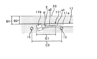
図2は定着体付き継手11を折り曲げる際の条件を示す図である。本実施形態では、定着体付き継手11の鉄筋11aを、目地2の外面20から定着体11bまでの距離B1が、当該外面20から始点111までの距離B2以上となるように折り曲げることで、定着体付き継手11のかぶり厚さを、目地2の外面20から鉄筋11aまでの距離B2とできる。
FIG. 2 is a diagram showing conditions for bending the
本実施形態では定着体付き継手11が目地2の最外縁にあるので、上記の距離B2が目地2のかぶり厚さの最小値となり、距離B2が所定の値となるように目地2の厚さを決定できる。
In this embodiment, since the
また、鉄筋11aの始点111から定着体11bの先端までの部分C1は、例えばブロック1の配列方向に隣り合う補強筋15のピッチC2内に収まるように配置される。さらに、鉄筋11aの折り曲げ角度、すなわち、始点111直前の鉄筋11aの方向a1に対し始点111から定着体11bに向かう方向a2がなす角度αは、例えば10度前後など、20度以下とするとよい。
Further, a portion C1 from the
上記のように、定着体付き継手11は少し曲げるだけとすることで、他の補強筋15等との干渉も少なく配筋作業の妨げにもならない。
As described above, by simply bending the
この継手構造10を構築するには、上記のように折り曲げた定着体付き継手11を設けた一対のブロック1を、図1に示すように対向配置した後、補強筋15等の配筋を行い、ブロック1間にコンクリートを打設して目地2を形成すればよい。
In order to construct the
図3は継手構造10を含む構造体の例であるLNG(Liquefied Natural
Gas;液化天然ガス)タンク100を示す図である。LNGタンク100は、LNGを貯蔵する地上式のタンクであり、底版50に防液堤30を設け、その内側に金属板等による内槽(不図示)と外槽40を設置したものである。
FIG. 3 shows an example of a structure including the
1 is a diagram illustrating a gas (liquefied natural gas)
防液堤30は、内槽や外槽40が破損等した場合にもLNGの外部への液漏れを防ぐために設けられる。本実施形態では、この防液堤30を、ブロック1を防液堤30の周方向に並べるとともに鉛直方向へと積み上げて構築する。その際、ブロック1の定着体付き継手11を前記のように折り曲げたうえで隣り合うブロック1の間に目地2を形成し、これにより継手構造10が構築される。
The
図1では継手構造10として水平方向にブロック1を配列した場合を示したが、目地2を挟んで鉛直方向にブロック1を配列する場合でも同様の継手構造10が構築される。なお、防液堤30では鉛直方向および周方向の緊張材(不図示)によりプレストレスが導入され、ブロック1では緊張材を通すためのシース管(不図示)なども設けられる。
Although FIG. 1 shows the case where the
以上説明したように、本実施形態によれば、定着体付き継手11を折り曲げることで、目地2の外面20から定着体11bまでの距離を大きくでき、定着体付き継手11のかぶり厚さを大きくできる。従って、目地2を厚くせずとも所定のかぶり厚さを確保でき経済的である。さらに定着体11bが目地2の深くに埋め込まれることになるから、定着効果もより大きくなる。
As described above, according to the present embodiment, by bending the joint 11 with the fixing body, the distance from the
本実施形態では、定着体付き継手11を、定着体11bと外面20との距離B1が、鉄筋11aの始点111と外面20との距離B2以上となるように折り曲げることで、定着体付き継手11のかぶり厚さが外面20から鉄筋11aまでの距離となり、定着体11bの無い通常の継手と変わらないかぶり厚さとできる。
In the present embodiment, the joint 11 with the fixing
本実施形態では、定着体付き継手11が目地2の最外縁にあり、定着体付き継手11のかぶり厚さが目地2のかぶり厚さの最小値となるので、目地2の厚さの設計時に重要となり、定着体付き継手11を折り曲げることが特に有効となる。
In the present embodiment, the joint 11 with the fixing body is at the outermost edge of the joint 2, and the cover thickness of the joint 11 with the fixing body is the minimum value of the cover thickness of the
また、本実施形態では、定着体付き継手11の鉄筋11aを折り曲げる始点111から定着体11bまでの部分を補強筋15のピッチ内に収め、折り曲げ角度を20度以下とすることで、定着体付き継手11を少し曲げるだけとし、他の補強筋15等との干渉も少なく配筋作業の妨げにもならない。
Further, in the present embodiment, the portion from the
しかしながら、本発明は上記に限ることはない。例えば本実施形態では継手構造10を有する構造体の例としてLNGタンク100を示したが、これに限らず、継手構造10は各種の構造体に適用することができる。その例として、プレキャストブロックによる柱部材同士の接続、梁部材同士の接続、あるいは柱部材と梁部材の接続等にも適用することが可能である。
However, the present invention is not limited to the above. For example, although the
また、本実施形態では図1に示すように目地2の厚さ方向(図の上下方向に対応する)の両側の定着体付き継手11を折り曲げているが、これに限らず、片側だけで定着体付き継手11を折り曲げてもよい。さらに、定着体11bの形状なども、鉄筋11aより幅が広ければ特に限定されることはない。
Further, in the present embodiment, as shown in FIG. 1, the
[第2の実施形態]
次に、本発明の第2の実施形態について説明する。第2の実施形態は第1の実施形態と異なる点について主に説明し、同様の点については図等で同じ符号を付すなどして説明を省略する。
[Second Embodiment]
Next, a second embodiment of the present invention will be described. The second embodiment will mainly describe differences from the first embodiment, and the same points will be denoted by the same reference numerals in the drawings and the like, and description thereof will be omitted.
第2の実施形態では、図4(a)に示すように定着体付き継手11が目地2の最外縁になく、定着体付き継手11の鉄筋11aよりも目地2の外面20に近い位置に補強筋15が配置される。ただし、定着体11bの幅が大きいことにより、外面20から定着体11bまでの距離Aが、外面20から補強筋15までの距離より小さくなっている。
In the second embodiment, as shown in FIG. 4A, the joint 11 with the fixing body is not located at the outermost edge of the joint 2, and is reinforced at a position closer to the
この場合も、図4(b)の継手構造10aに示すように、定着体付き継手11を、鉄筋11aの途中の始点111から定着体11bにかけて、始点111に最も近い目地2の外面20から内側へ向かう方向へと折り曲げることが有効である。
Also in this case, as shown in the joint structure 10a of FIG. 4B, the joint 11 with the fixing body is formed from the
図4(c)は、定着体付き継手11を折り曲げる際の条件を示す図である。第2の実施形態では、定着体付き継手11の鉄筋11aを、目地2の外面20から定着体11bまでの距離B1が、当該外面20から補強筋15までの距離B2以上となるように折り曲げることで、目地2のかぶり厚さの最小値が目地2の外面20から補強筋15までの距離B2となり、この距離B2が所定の値となるように目地2の厚さを決定できる。
FIG. 4C is a diagram showing conditions for bending the joint 11 with the fixing body. In the second embodiment, the reinforcing
なお、鉄筋11aの始点111から定着体11bの先端までの部分C1は、例えば前記と同様、補強筋15のピッチC2内に収めるように配置できる。鉄筋11aの折り曲げ角度についても前記と同様とできる。
The portion C1 from the
第2の実施形態でも第1の実施形態と同様の効果が得られ、目地2の外面20から定着体11bまでの距離を大きくすることで、目地2を厚くせずとも所定のかぶり厚さを確保できるようになり経済的である。
In the second embodiment, the same effect as that of the first embodiment can be obtained. By increasing the distance from the
以上、添付図面を参照して、本発明の好適な実施形態について説明したが、本発明は係る例に限定されない。当業者であれば、本願で開示した技術的思想の範疇内において、各種の変更例または修正例に想到し得ることは明らかであり、それらについても当然に本発明の技術的範囲に属するものと了解される。 The preferred embodiments of the present invention have been described above with reference to the accompanying drawings, but the present invention is not limited to such examples. It will be apparent to those skilled in the art that various changes or modifications can be conceived within the scope of the technical idea disclosed in the present application, and these are naturally within the technical scope of the present invention. Understood.
1;プレキャストブロック
2;目地
10、10a;継手構造
11;定着体付き継手
11a;鉄筋
11b;定着体
15;補強筋
20;外面
111;始点
30;防液堤
40;外槽
50;底版
100;LNGタンク
DESCRIPTION OF
Claims (6)
前記プレキャストブロックは、前記プレキャストブロックから突出する棒材の先端部に前記棒材より幅の大きな定着体を設けた定着体付き継手を有し、
一対の前記プレキャストブロックが目地を挟んで配列され、
前記目地には、それぞれの前記プレキャストブロックの前記定着体付き継手が埋設され、
それぞれの前記プレキャストブロックの前記定着体付き継手は、前記棒材の途中の始点から前記定着体にかけて、前記目地の前記始点に最も近い外面から前記目地の内側に向かう方向に折り曲げられ、
一方の前記プレキャストブロックの前記定着体付き継手の前記棒材の当該プレキャストブロックから前記始点までの部分と、他方の前記プレキャストブロックの前記定着体付き継手の前記棒材の当該プレキャストブロックから前記始点までの部分とが、前記棒材と直交しかつ前記外面と平行な方向から見たときに重複して配置されていることを特徴とする継手構造。 A joint structure between precast blocks of the same member thickness ,
The precast block has a joint with a fixing body in which a fixing body having a width larger than the bar is provided at a tip portion of the bar protruding from the precast block,
A pair of the precast blocks are arranged across the joint,
In the joint, the joint with the fixing body of each precast block is embedded,
The joint with the fixing body of each of the precast blocks is bent in the direction from the outer surface closest to the starting point of the joint toward the inside of the joint from the middle starting point of the bar to the fixing body,
From the precast block to the start point of the bar of the joint with the fixing body of one of the precast blocks and from the precast block to the start point of the bar of the joint with the fixing body of the other precast block The joint structure is arranged so as to overlap when viewed from a direction orthogonal to the bar and parallel to the outer surface.
前記棒材の前記始点から前記定着体の先端までの部分が、隣り合う前記補強筋の前記配列方向のピッチ内に収まることを特徴とする請求項1または請求項2に記載の継手構造。 In the joint, a plurality of reinforcing bars in a direction orthogonal to the bar and parallel to the outer surface are provided in the vicinity of the joint with the fixing body along the arrangement direction in which the precast blocks are arranged,
3. The joint structure according to claim 1, wherein a portion from the starting point of the bar to the tip of the fixing body is within a pitch in the arrangement direction of the adjacent reinforcing bars.
前記棒材の前記プレキャストブロックから前記始点までの部分が、前記補強筋よりも前記外面に近い位置に配置されることを特徴とする請求項1から請求項4のいずれかに記載の継手構造。 In the joint, a plurality of reinforcing bars in a direction orthogonal to the bar and parallel to the outer surface are provided in the vicinity of the joint with the fixing body along the arrangement direction in which the precast blocks are arranged,
The joint structure according to any one of claims 1 to 4, wherein a portion of the bar from the precast block to the start point is disposed at a position closer to the outer surface than the reinforcing bar.
Priority Applications (1)
| Application Number | Priority Date | Filing Date | Title |
|---|---|---|---|
| JP2014076688A JP6470908B2 (en) | 2014-04-03 | 2014-04-03 | Fitting structure, breakwater |
Applications Claiming Priority (1)
| Application Number | Priority Date | Filing Date | Title |
|---|---|---|---|
| JP2014076688A JP6470908B2 (en) | 2014-04-03 | 2014-04-03 | Fitting structure, breakwater |
Publications (2)
| Publication Number | Publication Date |
|---|---|
| JP2015197017A JP2015197017A (en) | 2015-11-09 |
| JP6470908B2 true JP6470908B2 (en) | 2019-02-13 |
Family
ID=54546873
Family Applications (1)
| Application Number | Title | Priority Date | Filing Date |
|---|---|---|---|
| JP2014076688A Active JP6470908B2 (en) | 2014-04-03 | 2014-04-03 | Fitting structure, breakwater |
Country Status (1)
| Country | Link |
|---|---|
| JP (1) | JP6470908B2 (en) |
Families Citing this family (2)
| Publication number | Priority date | Publication date | Assignee | Title |
|---|---|---|---|---|
| JP2017036554A (en) * | 2015-08-07 | 2017-02-16 | 株式会社ピーエス三菱 | Cast-in-place joint structure of precast floor slab |
| JP6752120B2 (en) * | 2016-11-14 | 2020-09-09 | 鹿島建設株式会社 | Connection structure and connection method |
Family Cites Families (5)
| Publication number | Priority date | Publication date | Assignee | Title |
|---|---|---|---|---|
| JPS4981320U (en) * | 1972-10-30 | 1974-07-15 | ||
| JPH0714745B2 (en) * | 1990-05-02 | 1995-02-22 | 機動建設工業株式会社 | PC tank construction method and panel material |
| US7162844B2 (en) * | 2003-01-09 | 2007-01-16 | Chicago Bridge & Iron Company | Use of partial precast panels for construction of concrete walls and shells |
| JP2005016002A (en) * | 2003-06-23 | 2005-01-20 | East Japan Railway Co | Joining structure of reinforced concrete, construction method for reinforced concrete skeleton, construction method for reinforced concrete, and joining method for reinforced concrete |
| JP2009293289A (en) * | 2008-06-05 | 2009-12-17 | Takenaka Komuten Co Ltd | Reinforced concrete beam |
-
2014
- 2014-04-03 JP JP2014076688A patent/JP6470908B2/en active Active
Also Published As
| Publication number | Publication date |
|---|---|
| JP2015197017A (en) | 2015-11-09 |
Similar Documents
| Publication | Publication Date | Title |
|---|---|---|
| JP2015187017A5 (en) | ||
| KR20120013233A (en) | Liquefied Natural Gas storage tank and method to manufacture the same | |
| TR201500976T1 (en) | Axially flexible elasto-plastic hysteresis support and vibration-damping steel frame structure. | |
| JP6470908B2 (en) | Fitting structure, breakwater | |
| JP2017106306A (en) | Segments | |
| JP5554441B2 (en) | End joint structure of steel pipe members | |
| JP5939622B2 (en) | Retaining wall | |
| JP5418838B2 (en) | Steel pipe sheet pile wall | |
| JP5603667B2 (en) | Reinforcement structure of the opening provided in the joint hardware part | |
| CN102213012B (en) | Buckling restrained brace and side shell pieces and manufacturing method thereof | |
| JP5837130B2 (en) | Structure and structure construction method | |
| JP2007177546A (en) | Earthquake resisting wall of reinforced concrete construction | |
| JP6041144B2 (en) | Top floor joint structure | |
| JP4298678B2 (en) | Connection structure | |
| JP6548506B2 (en) | Wall and wall construction method | |
| JP6894107B2 (en) | Flexible water stop plate | |
| JP6581402B2 (en) | Precast concrete beam and method of joining precast concrete beam | |
| JP4751207B2 (en) | Connection structure of circular steel pipe column and H-section steel beam and pier using the connection structure | |
| JP5885566B2 (en) | Xiamen collar structure and method for constructing box joint using the structure | |
| JP5867326B2 (en) | Steel sheet pile and wall body using the same | |
| JP2019031780A (en) | Crack inducing joint structure | |
| JP6313067B2 (en) | Damping damper | |
| JP6497482B2 (en) | Beam-column joint structure | |
| JP2015175102A (en) | Eaves gutter joint, and joint structure for eaves gutter joint and eaves gutter | |
| JP6966192B2 (en) | Method for determining construction defects of seismic slit materials |
Legal Events
| Date | Code | Title | Description |
|---|---|---|---|
| A621 | Written request for application examination |
Free format text: JAPANESE INTERMEDIATE CODE: A621 Effective date: 20170313 |
|
| A977 | Report on retrieval |
Free format text: JAPANESE INTERMEDIATE CODE: A971007 Effective date: 20171208 |
|
| A131 | Notification of reasons for refusal |
Free format text: JAPANESE INTERMEDIATE CODE: A131 Effective date: 20171219 |
|
| A521 | Request for written amendment filed |
Free format text: JAPANESE INTERMEDIATE CODE: A523 Effective date: 20180206 |
|
| A131 | Notification of reasons for refusal |
Free format text: JAPANESE INTERMEDIATE CODE: A131 Effective date: 20180612 |
|
| A521 | Request for written amendment filed |
Free format text: JAPANESE INTERMEDIATE CODE: A523 Effective date: 20180803 |
|
| TRDD | Decision of grant or rejection written | ||
| A01 | Written decision to grant a patent or to grant a registration (utility model) |
Free format text: JAPANESE INTERMEDIATE CODE: A01 Effective date: 20190115 |
|
| A61 | First payment of annual fees (during grant procedure) |
Free format text: JAPANESE INTERMEDIATE CODE: A61 Effective date: 20190121 |
|
| R150 | Certificate of patent or registration of utility model |
Ref document number: 6470908 Country of ref document: JP Free format text: JAPANESE INTERMEDIATE CODE: R150 |
|
| R250 | Receipt of annual fees |
Free format text: JAPANESE INTERMEDIATE CODE: R250 |