JP6470177B2 - Implantable access port with sandwiched radiopaque insert - Google Patents
Implantable access port with sandwiched radiopaque insert Download PDFInfo
- Publication number
- JP6470177B2 JP6470177B2 JP2015528624A JP2015528624A JP6470177B2 JP 6470177 B2 JP6470177 B2 JP 6470177B2 JP 2015528624 A JP2015528624 A JP 2015528624A JP 2015528624 A JP2015528624 A JP 2015528624A JP 6470177 B2 JP6470177 B2 JP 6470177B2
- Authority
- JP
- Japan
- Prior art keywords
- access port
- port
- insert
- radiopaque
- base portion
- Prior art date
- Legal status (The legal status is an assumption and is not a legal conclusion. Google has not performed a legal analysis and makes no representation as to the accuracy of the status listed.)
- Active
Links
- 239000000463 material Substances 0.000 claims description 85
- 238000000034 method Methods 0.000 claims description 42
- 239000012530 fluid Substances 0.000 claims description 35
- 238000003384 imaging method Methods 0.000 claims description 26
- 238000002513 implantation Methods 0.000 claims description 24
- 239000000203 mixture Substances 0.000 claims description 22
- 125000000218 acetic acid group Chemical group C(C)(=O)* 0.000 claims description 19
- 229920005989 resin Polymers 0.000 claims description 19
- 239000011347 resin Substances 0.000 claims description 19
- WMWLMWRWZQELOS-UHFFFAOYSA-N bismuth(III) oxide Inorganic materials O=[Bi]O[Bi]=O WMWLMWRWZQELOS-UHFFFAOYSA-N 0.000 claims description 18
- 238000004891 communication Methods 0.000 claims description 13
- 238000004519 manufacturing process Methods 0.000 claims description 12
- 238000003466 welding Methods 0.000 claims description 12
- 239000004696 Poly ether ether ketone Substances 0.000 claims description 9
- 229920002530 polyetherether ketone Polymers 0.000 claims description 9
- 238000001746 injection moulding Methods 0.000 claims description 6
- 238000007920 subcutaneous administration Methods 0.000 claims description 6
- GWEVSGVZZGPLCZ-UHFFFAOYSA-N Titan oxide Chemical compound O=[Ti]=O GWEVSGVZZGPLCZ-UHFFFAOYSA-N 0.000 claims description 4
- 229940073609 bismuth oxychloride Drugs 0.000 claims description 4
- 238000001802 infusion Methods 0.000 claims description 4
- BWOROQSFKKODDR-UHFFFAOYSA-N oxobismuth;hydrochloride Chemical compound Cl.[Bi]=O BWOROQSFKKODDR-UHFFFAOYSA-N 0.000 claims description 4
- RVTZCBVAJQQJTK-UHFFFAOYSA-N oxygen(2-);zirconium(4+) Chemical compound [O-2].[O-2].[Zr+4] RVTZCBVAJQQJTK-UHFFFAOYSA-N 0.000 claims description 4
- 229910001928 zirconium oxide Inorganic materials 0.000 claims description 4
- 150000001875 compounds Chemical class 0.000 claims description 3
- 238000003780 insertion Methods 0.000 claims description 3
- 230000037431 insertion Effects 0.000 claims description 3
- 229910000014 Bismuth subcarbonate Inorganic materials 0.000 claims description 2
- MGLUJXPJRXTKJM-UHFFFAOYSA-L bismuth subcarbonate Chemical compound O=[Bi]OC(=O)O[Bi]=O MGLUJXPJRXTKJM-UHFFFAOYSA-L 0.000 claims description 2
- 229940036358 bismuth subcarbonate Drugs 0.000 claims description 2
- TWNQGVIAIRXVLR-UHFFFAOYSA-N oxo(oxoalumanyloxy)alumane Chemical compound O=[Al]O[Al]=O TWNQGVIAIRXVLR-UHFFFAOYSA-N 0.000 claims description 2
- 239000004408 titanium dioxide Substances 0.000 claims description 2
- 229910052797 bismuth Inorganic materials 0.000 claims 2
- JCXGWMGPZLAOME-UHFFFAOYSA-N bismuth atom Chemical compound [Bi] JCXGWMGPZLAOME-UHFFFAOYSA-N 0.000 claims 2
- 229940024548 aluminum oxide Drugs 0.000 claims 1
- 229960005196 titanium dioxide Drugs 0.000 claims 1
- 229940043774 zirconium oxide Drugs 0.000 claims 1
- 239000000758 substrate Substances 0.000 description 35
- 230000008569 process Effects 0.000 description 23
- 238000012876 topography Methods 0.000 description 22
- 238000000465 moulding Methods 0.000 description 17
- 239000000976 ink Substances 0.000 description 15
- 238000002347 injection Methods 0.000 description 13
- 239000007924 injection Substances 0.000 description 13
- 239000000843 powder Substances 0.000 description 13
- 229910052751 metal Inorganic materials 0.000 description 11
- 239000002184 metal Substances 0.000 description 11
- TZCXTZWJZNENPQ-UHFFFAOYSA-L barium sulfate Chemical compound [Ba+2].[O-]S([O-])(=O)=O TZCXTZWJZNENPQ-UHFFFAOYSA-L 0.000 description 10
- 238000002559 palpation Methods 0.000 description 9
- 229920001296 polysiloxane Polymers 0.000 description 9
- 230000000875 corresponding effect Effects 0.000 description 8
- 230000003993 interaction Effects 0.000 description 8
- WFKWXMTUELFFGS-UHFFFAOYSA-N tungsten Chemical compound [W] WFKWXMTUELFFGS-UHFFFAOYSA-N 0.000 description 8
- RTAQQCXQSZGOHL-UHFFFAOYSA-N Titanium Chemical compound [Ti] RTAQQCXQSZGOHL-UHFFFAOYSA-N 0.000 description 7
- 238000010586 diagram Methods 0.000 description 7
- 239000010936 titanium Substances 0.000 description 7
- 229910052719 titanium Inorganic materials 0.000 description 7
- 230000007704 transition Effects 0.000 description 7
- 239000000853 adhesive Substances 0.000 description 6
- 230000001070 adhesive effect Effects 0.000 description 6
- JUPQTSLXMOCDHR-UHFFFAOYSA-N benzene-1,4-diol;bis(4-fluorophenyl)methanone Chemical compound OC1=CC=C(O)C=C1.C1=CC(F)=CC=C1C(=O)C1=CC=C(F)C=C1 JUPQTSLXMOCDHR-UHFFFAOYSA-N 0.000 description 6
- 238000013461 design Methods 0.000 description 6
- 238000005516 engineering process Methods 0.000 description 6
- 239000004033 plastic Substances 0.000 description 6
- 229920003023 plastic Polymers 0.000 description 6
- 230000008901 benefit Effects 0.000 description 5
- 239000000945 filler Substances 0.000 description 5
- 238000002595 magnetic resonance imaging Methods 0.000 description 5
- 230000013011 mating Effects 0.000 description 5
- 230000005855 radiation Effects 0.000 description 5
- 238000002604 ultrasonography Methods 0.000 description 5
- 230000015572 biosynthetic process Effects 0.000 description 4
- 238000003754 machining Methods 0.000 description 4
- 239000007769 metal material Substances 0.000 description 4
- 230000002093 peripheral effect Effects 0.000 description 4
- 229910052721 tungsten Inorganic materials 0.000 description 4
- 239000010937 tungsten Substances 0.000 description 4
- 229920004943 Delrin® Polymers 0.000 description 3
- 239000000560 biocompatible material Substances 0.000 description 3
- 239000000919 ceramic Substances 0.000 description 3
- 239000002872 contrast media Substances 0.000 description 3
- 230000002596 correlated effect Effects 0.000 description 3
- 238000005520 cutting process Methods 0.000 description 3
- 230000009977 dual effect Effects 0.000 description 3
- 238000011049 filling Methods 0.000 description 3
- 238000010348 incorporation Methods 0.000 description 3
- -1 snow Substances 0.000 description 3
- MCMNRKCIXSYSNV-UHFFFAOYSA-N Zirconium dioxide Chemical compound O=[Zr]=O MCMNRKCIXSYSNV-UHFFFAOYSA-N 0.000 description 2
- 239000002131 composite material Substances 0.000 description 2
- 238000002591 computed tomography Methods 0.000 description 2
- 238000005530 etching Methods 0.000 description 2
- 238000001125 extrusion Methods 0.000 description 2
- 230000010354 integration Effects 0.000 description 2
- 239000003550 marker Substances 0.000 description 2
- 238000002156 mixing Methods 0.000 description 2
- 230000036961 partial effect Effects 0.000 description 2
- 230000008447 perception Effects 0.000 description 2
- 230000010399 physical interaction Effects 0.000 description 2
- 229920006324 polyoxymethylene Polymers 0.000 description 2
- 238000007639 printing Methods 0.000 description 2
- 239000000126 substance Substances 0.000 description 2
- 230000000007 visual effect Effects 0.000 description 2
- 238000011179 visual inspection Methods 0.000 description 2
- FFMASFPOJYXQSA-UHFFFAOYSA-H C(=O)([O-])OC(=O)OC(=O)[O-].[Bi+3].C(=O)([O-])OC(=O)OC(=O)[O-].C(=O)([O-])OC(=O)OC(=O)[O-].[Bi+3] Chemical compound C(=O)([O-])OC(=O)OC(=O)[O-].[Bi+3].C(=O)([O-])OC(=O)OC(=O)[O-].C(=O)([O-])OC(=O)OC(=O)[O-].[Bi+3] FFMASFPOJYXQSA-UHFFFAOYSA-H 0.000 description 1
- JOYRKODLDBILNP-UHFFFAOYSA-N Ethyl urethane Chemical compound CCOC(N)=O JOYRKODLDBILNP-UHFFFAOYSA-N 0.000 description 1
- 229920004039 Makrolon® 2558 Polymers 0.000 description 1
- 229930040373 Paraformaldehyde Natural products 0.000 description 1
- 239000004775 Tyvek Substances 0.000 description 1
- 229920000690 Tyvek Polymers 0.000 description 1
- 230000001133 acceleration Effects 0.000 description 1
- 238000007792 addition Methods 0.000 description 1
- 239000000654 additive Substances 0.000 description 1
- PNEYBMLMFCGWSK-UHFFFAOYSA-N aluminium oxide Inorganic materials [O-2].[O-2].[O-2].[Al+3].[Al+3] PNEYBMLMFCGWSK-UHFFFAOYSA-N 0.000 description 1
- 238000004873 anchoring Methods 0.000 description 1
- 238000013459 approach Methods 0.000 description 1
- 239000011324 bead Substances 0.000 description 1
- 230000009286 beneficial effect Effects 0.000 description 1
- 229940036348 bismuth carbonate Drugs 0.000 description 1
- 150000001622 bismuth compounds Chemical class 0.000 description 1
- 238000005266 casting Methods 0.000 description 1
- 230000008859 change Effects 0.000 description 1
- 238000005234 chemical deposition Methods 0.000 description 1
- 238000003486 chemical etching Methods 0.000 description 1
- 239000003795 chemical substances by application Substances 0.000 description 1
- 238000013037 co-molding Methods 0.000 description 1
- 230000000295 complement effect Effects 0.000 description 1
- 238000012790 confirmation Methods 0.000 description 1
- 230000008602 contraction Effects 0.000 description 1
- 230000003247 decreasing effect Effects 0.000 description 1
- 238000001514 detection method Methods 0.000 description 1
- 238000003745 diagnosis Methods 0.000 description 1
- GMZOPRQQINFLPQ-UHFFFAOYSA-H dibismuth;tricarbonate Chemical compound [Bi+3].[Bi+3].[O-]C([O-])=O.[O-]C([O-])=O.[O-]C([O-])=O GMZOPRQQINFLPQ-UHFFFAOYSA-H 0.000 description 1
- 229920001971 elastomer Polymers 0.000 description 1
- 238000005538 encapsulation Methods 0.000 description 1
- 230000001747 exhibiting effect Effects 0.000 description 1
- 238000005242 forging Methods 0.000 description 1
- PCHJSUWPFVWCPO-UHFFFAOYSA-N gold Chemical compound [Au] PCHJSUWPFVWCPO-UHFFFAOYSA-N 0.000 description 1
- 229910052737 gold Inorganic materials 0.000 description 1
- 239000010931 gold Substances 0.000 description 1
- 230000005484 gravity Effects 0.000 description 1
- 238000000227 grinding Methods 0.000 description 1
- 229920001903 high density polyethylene Polymers 0.000 description 1
- 239000004700 high-density polyethylene Substances 0.000 description 1
- 208000015181 infectious disease Diseases 0.000 description 1
- 230000002401 inhibitory effect Effects 0.000 description 1
- 238000007641 inkjet printing Methods 0.000 description 1
- 238000010329 laser etching Methods 0.000 description 1
- 230000000670 limiting effect Effects 0.000 description 1
- 239000007788 liquid Substances 0.000 description 1
- 230000007774 longterm Effects 0.000 description 1
- 229910044991 metal oxide Inorganic materials 0.000 description 1
- 150000004706 metal oxides Chemical class 0.000 description 1
- 210000004080 milk Anatomy 0.000 description 1
- 235000013336 milk Nutrition 0.000 description 1
- 238000012986 modification Methods 0.000 description 1
- 230000004048 modification Effects 0.000 description 1
- 229910000510 noble metal Inorganic materials 0.000 description 1
- 230000003287 optical effect Effects 0.000 description 1
- 238000007649 pad printing Methods 0.000 description 1
- 239000003973 paint Substances 0.000 description 1
- 239000002245 particle Substances 0.000 description 1
- 230000037368 penetrate the skin Effects 0.000 description 1
- 230000035515 penetration Effects 0.000 description 1
- 238000005289 physical deposition Methods 0.000 description 1
- 229920002492 poly(sulfone) Polymers 0.000 description 1
- 229920000515 polycarbonate Polymers 0.000 description 1
- 239000004417 polycarbonate Substances 0.000 description 1
- 238000002360 preparation method Methods 0.000 description 1
- 230000004044 response Effects 0.000 description 1
- 230000000717 retained effect Effects 0.000 description 1
- 238000007789 sealing Methods 0.000 description 1
- 238000000926 separation method Methods 0.000 description 1
- 230000035939 shock Effects 0.000 description 1
- 229920000260 silastic Polymers 0.000 description 1
- 229910052709 silver Inorganic materials 0.000 description 1
- 239000004332 silver Substances 0.000 description 1
- 239000007787 solid Substances 0.000 description 1
- 229910001220 stainless steel Inorganic materials 0.000 description 1
- 239000010935 stainless steel Substances 0.000 description 1
- 150000003467 sulfuric acid derivatives Chemical class 0.000 description 1
- 238000001356 surgical procedure Methods 0.000 description 1
- 229910052715 tantalum Inorganic materials 0.000 description 1
- GUVRBAGPIYLISA-UHFFFAOYSA-N tantalum atom Chemical compound [Ta] GUVRBAGPIYLISA-UHFFFAOYSA-N 0.000 description 1
- 238000012360 testing method Methods 0.000 description 1
- 229920001169 thermoplastic Polymers 0.000 description 1
- 239000012815 thermoplastic material Substances 0.000 description 1
- 229920005992 thermoplastic resin Polymers 0.000 description 1
- 239000004416 thermosoftening plastic Substances 0.000 description 1
- 238000012546 transfer Methods 0.000 description 1
- 230000001960 triggered effect Effects 0.000 description 1
- 230000007306 turnover Effects 0.000 description 1
- 210000003462 vein Anatomy 0.000 description 1
Images


Classifications
-
- A—HUMAN NECESSITIES
- A61—MEDICAL OR VETERINARY SCIENCE; HYGIENE
- A61M—DEVICES FOR INTRODUCING MEDIA INTO, OR ONTO, THE BODY; DEVICES FOR TRANSDUCING BODY MEDIA OR FOR TAKING MEDIA FROM THE BODY; DEVICES FOR PRODUCING OR ENDING SLEEP OR STUPOR
- A61M39/00—Tubes, tube connectors, tube couplings, valves, access sites or the like, specially adapted for medical use
- A61M39/02—Access sites
- A61M39/0208—Subcutaneous access sites for injecting or removing fluids
-
- A—HUMAN NECESSITIES
- A61—MEDICAL OR VETERINARY SCIENCE; HYGIENE
- A61B—DIAGNOSIS; SURGERY; IDENTIFICATION
- A61B90/00—Instruments, implements or accessories specially adapted for surgery or diagnosis and not covered by any of the groups A61B1/00 - A61B50/00, e.g. for luxation treatment or for protecting wound edges
- A61B90/90—Identification means for patients or instruments, e.g. tags
- A61B90/94—Identification means for patients or instruments, e.g. tags coded with symbols, e.g. text
-
- A—HUMAN NECESSITIES
- A61—MEDICAL OR VETERINARY SCIENCE; HYGIENE
- A61B—DIAGNOSIS; SURGERY; IDENTIFICATION
- A61B90/00—Instruments, implements or accessories specially adapted for surgery or diagnosis and not covered by any of the groups A61B1/00 - A61B50/00, e.g. for luxation treatment or for protecting wound edges
- A61B90/39—Markers, e.g. radio-opaque or breast lesions markers
- A61B2090/3966—Radiopaque markers visible in an X-ray image
-
- A—HUMAN NECESSITIES
- A61—MEDICAL OR VETERINARY SCIENCE; HYGIENE
- A61M—DEVICES FOR INTRODUCING MEDIA INTO, OR ONTO, THE BODY; DEVICES FOR TRANSDUCING BODY MEDIA OR FOR TAKING MEDIA FROM THE BODY; DEVICES FOR PRODUCING OR ENDING SLEEP OR STUPOR
- A61M39/00—Tubes, tube connectors, tube couplings, valves, access sites or the like, specially adapted for medical use
- A61M39/02—Access sites
- A61M39/0208—Subcutaneous access sites for injecting or removing fluids
- A61M2039/0238—Subcutaneous access sites for injecting or removing fluids having means for locating the implanted device to insure proper injection, e.g. radio-emitter, protuberances, radio-opaque markers
Description
[0001]本出願は、2012年8月21日出願、米国特許仮出願第61/691,725号、表題「Implantable Access Port Including Sandwiched Radiopaque Insert」の利益を主張する。本出願はまた、2013年2月25日出願、米国特許出願第13/776,517号の一部継続でもあり、該出願は2011年9月30日出願、米国特許出願第13/250,909号、現在の米国特許第8,382,724号の分割であり、該出願は2010年6月8日出願、米国特許出願第12/796,133号、現在の米国特許第8,029,482号の分割であり、該出願は2009年10月30日出願、米国特許出願第12/610,084号、現在の米国特許第8,202,259号の一部継続であり、該出願は2008年10月31日出願、米国特許仮出願第61/110,507号、表題「Radiopaque and Radiographically Discernible Indicators for an Implantable Port」の利益を主張し、2009年4月7日出願、米国特許出願第12/420,028号、現在の米国特許第7,947,022号の一部継続であり、該出願は2006年3月6日出願、米国特許出願第11/368,954号、現在の米国特許第7,785,302号の一部継続であり、該出願は2005年3月4日出願、米国特許仮出願第60/658,518号、表題「Access Port Identification System」の利益を主張する。上記に参照した出願のそれぞれは、この参照によりその全体が組み込まれる。
[0001] This application claims the benefit of US Provisional Application No. 61 / 691,725, entitled “Implantable Access Ported Sandwiched Radiopaque Insert”, filed Aug. 21, 2012. This application is also a continuation of US application Ser. No. 13 / 776,517, filed Feb. 25, 2013, which filed Sep. 30, 2011, US application Ser. No. 13 / 250,909. US patent application Ser. No. 8,382,724, filed June 8, 2010, US patent application Ser. No. 12 / 796,133, current US Pat. No. 8,029,482. Which is a continuation of US patent application Ser. No. 12 / 610,084, current US Pat. No. 8,202,259, which was filed on Oct. 30, 2009. No. 61 / 110,507, filed Oct. 31, 2000, entitled “Radiopaque and Radiographically Dissimilar Indicators for an” Claiming the benefit of “Implantable Port” and is a continuation of US patent application Ser. No. 12 / 420,028, now US Pat. No. 7,947,022, filed Apr. 7, 2009. US Patent Application No. 11 / 368,954, which is a continuation of part of the present US Patent No. 7,785,302, which was filed on March 4, 2005, Claims the benefit of
[0080]本開示は、概して経皮アクセスに、及びより具体的には、経皮アクセスに関連する方法及び装置に関する。概して、本開示は、皮下埋め込みのためのアクセスポートに関する。一実施形態では、アクセスポートは、医師又は他の医療従事者が患者の身体の内部への長期的な経皮アクセスを得ることを可能にし得る。経皮アクセスのためのアクセスポートを用いることは、患者の皮膚から及び外部環境からの(患者の身体の内部へと及ぶ)流体接続を阻害することによって、感染の機会を減らし得る。該アクセス装置は、皮膚を貫通する針を必要とすることなく、患者の内部へのアクセスを可能にする。さらに、カテーテル又は弁等の内部コンポーネントは、外科的処置を伴わずに交換され得る。本開示の特徴又は態様は、限定なしに、患者への皮下アクセスのための任意のかかるアクセスポートに適用し得る。アクセスポートは、例えば手で(例えば針を含む注射器によって)注入され得るか、又は機械的補助(例えばいわゆる高圧注入可能ポート)によって注入及び加圧され得る。 [0080] The present disclosure relates generally to percutaneous access, and more specifically to methods and devices related to percutaneous access. In general, the present disclosure relates to an access port for subcutaneous implantation. In one embodiment, the access port may allow a physician or other healthcare professional to gain long-term transcutaneous access to the interior of the patient's body. Using an access port for percutaneous access may reduce the chance of infection by inhibiting fluid connections from the patient's skin and from the external environment (which extends into the patient's body). The access device allows access to the patient's interior without the need for a needle to penetrate the skin. Furthermore, internal components such as catheters or valves can be replaced without surgical procedures. The features or aspects of the present disclosure may be applied to any such access port for subcutaneous access to a patient without limitation. The access port can be injected, for example, by hand (eg, with a syringe containing a needle) or can be injected and pressurized with mechanical assistance (eg, a so-called high pressure injectable port).
[0081]高圧注入可能ポートは、他のプロセスの中でもとりわけ、例えば、コンピュータ断層撮影(「CT」)走査プロセスにおいて用いられ得る。より具体的には、いわゆる「高圧注入器」システムが、末梢挿入静脈(IV)ラインに造影剤を注入するために用いられ得る。例えば、かかる高圧注入器又は注入システムは、ドイツのSchering AGの子会社であるMedrad,Inc.から商業的に入手可能であり得、商標STELLANT(登録商標)の下で市販され得る。流体注入手順はしばしば、造影剤の所望の流速に関して画定されるため、かかる高圧注入システムは概して、所望の流速を選択することによって制御可能である。 [0081] The high pressure injectable port may be used, for example, in a computed tomography ("CT") scanning process, among other processes. More specifically, a so-called “high pressure injector” system can be used to inject contrast agent into the peripheral insertion vein (IV) line. For example, such a high pressure injector or injection system is available from Medrad, Inc., a subsidiary of Schering AG, Germany. And can be obtained commercially under the trademark STELLANT®. Since fluid injection procedures are often defined in terms of the desired flow rate of the contrast agent, such high pressure injection systems are generally controllable by selecting the desired flow rate.
[0082]より具体的には、本開示は、アクセスポートを識別するための少なくとも1つの知覚可能又は識別可能な特徴を有するアクセスポートに関し、この識別可能な特徴は、アクセスポートが患者内に埋め込まれた後で知覚可能である。例えば、本開示によって企図されるアクセスポートの少なくとも1つ又はおそらく複数の識別可能な特徴(複数可)は、アクセスポートに属する情報(製造業者のモデル又は設計)に相関的であり得る。したがって、特定のモデルのアクセスポートからの識別可能な特徴は、異なるモデル又は設計の、別のアクセスポートの全てではなくともほとんどの他の識別可能な特徴に対して、固有のものとなり得る。当然のことながら、本開示によって企図されるアクセスポートの少なくとも1つの識別可能な特徴は、ポートの種類、カテーテルの種類、製造日、材料のロット、部品番号等のような、目的とする任意の情報とさらに相関的であり得る。一実施例では、アクセスポートの少なくとも1つの識別可能な特徴は、高圧注入可能であるアクセスポートと相関的であり得る。このように、アクセスポートの少なくとも1つの識別可能な特徴が観測又は別の方法で判定されると、アクセスポートのかかる少なくとも1つの特徴の相関が達成され得、アクセスポートに属する情報が得られ得る。 [0082] More specifically, the present disclosure relates to an access port having at least one perceptible or identifiable feature for identifying the access port, the identifiable feature being embedded in the patient. Is perceptible after For example, at least one or possibly multiple identifiable characteristic (s) of an access port contemplated by the present disclosure may be correlated to information belonging to the access port (manufacturer model or design). Thus, the identifiable features from a particular model access port can be unique to most if not all other identifiable features of a different model or design. Of course, at least one identifiable feature of an access port contemplated by this disclosure may be any desired target, such as port type, catheter type, date of manufacture, material lot, part number, etc. It can be further correlated with information. In one example, at least one identifiable feature of the access port may be correlated with an access port that is capable of high pressure injection. Thus, when at least one identifiable feature of an access port is observed or otherwise determined, a correlation of such at least one feature of the access port can be achieved and information belonging to the access port can be obtained. .
[0083]一実施形態では、少なくとも1つの特徴は、触診によって(すなわち触れることによって試験すること)、他の物理的相互作用によって、又は目視によって、知覚され得る。結果的に、関与する人物は、その少なくとも1つの識別特徴を知覚するために、皮膚を通してアクセスポートに触れ又はそれを感じ得る。別の実施形態では、少なくとも1つの識別可能な特徴は、X線又は超音波画像を介して知覚され得る。なおもさらなる実施形態では、少なくとも1つの識別可能な特徴は、アクセスポートとの、磁気、光、又はラジオ波エネルギー相互作用又は通信によって知覚され得る。 [0083] In one embodiment, at least one feature may be perceived by palpation (ie, testing by touching), by other physical interactions, or by visual inspection. As a result, the involved person can touch or feel the access port through the skin to perceive its at least one identifying feature. In another embodiment, the at least one identifiable feature can be perceived via X-rays or ultrasound images. In still further embodiments, the at least one identifiable feature may be perceived by magnetic, light, or radio frequency energy interaction or communication with the access port.
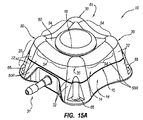
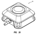
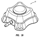
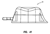
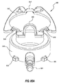
[0084]少なくとも1つの特徴が触診、他の物理的相互作用、又は目視によって知覚され得る実施形態を参照すると、本開示によって企図されるアクセスポートのトポグラフィー又は外面特徴は、知覚のために構成され得る。例えば、図1A及び1Bを参照すると、本開示によって企図される例示的アクセスポート10が示される。図1A及び1Bは、患者の身体への経皮又は別の方法での内部アクセスを可能にするためのアクセスポート10の、それぞれ斜視図及び概略側面断面図を示す。アクセスポート10は、キャップ14及びベース16によって画定される、ハウジング又は本体20を含む。キャップ14及びベース16は、当該技術分野において既知のように、その間でセプタム18を捕捉するために構成され得る。図1Aに示されるように、キャップ14及びベース16は、噛合線15に沿って互いに噛合により係合し得る。キャップ14及びベース16は、ねじ若しくは他の締結装置等の機械的締結具を介して互いに据付若しくは固着され得るか、互いに接着により固着され得るか、又は当該技術分野において既知であるように互いに固着され得る。さらに、キャップ14、ベース16、及びセプタム18は、排出口ステム31の内腔29と流体連通する腔36を、集合的に画定し得る。
[0084] Referring to embodiments in which at least one feature may be perceived by palpation, other physical interaction, or visual observation, the topography or exterior features of the access port contemplated by the present disclosure are configured for perception. Can be done. For example, referring to FIGS. 1A and 1B, an
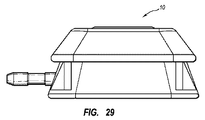
[0085]腔36を患者7内に皮下配置するために、本体20は、図1Bに示されるように患者7に埋め込まれ得る。また、縫合開孔部66(図1A)が、所望の場合、患者7内にアクセスポート10を固着するために使用され得る。本体20が患者7内に埋め込まれた後、セプタム18の上面は、患者7の皮膚6の表面と実質的に同一表面となり得、患者の皮膚の外部から腔36への経皮通路を作り出すために繰り返し穿刺され得る。排出口ステム31は、腔36から排出口ステム31を通り患者7の体内への流体連通通路を作り出し得る。腔36との流体連通のために、及び流体を腔36から、腔36からのかつ患者7内の所望の遠隔位置へと転送するために、カテーテルが排出口ステム31に結合され得る。
[0085] To place the
[0086]アクセスポート10の本体20は、ポリスルホン、チタン、アセチル樹脂、又は当該技術分野において既知の任意の他の好適な生体適合性材料等の、生体適合性材料を含み得る。結果的に、本体20は、生体適合性プラスチック材料から形成され得る。所望であれば、本体20は、縫合又は針による穿通のための穿通可能材料を含み得る。別の実施形態では、そして本明細書の以下でさらに記載するように、所望であれば、本体20は、例えば金属等の、穿通不可能な材料を含み得る。本体20は、限定なしに、凹面底を含み得、又は別の実施形態では平面底を含み得る。
[0086] The
[0087]本開示に従い、アクセスポート10は、少なくとも1つの識別可能な特徴を示す、本体20を含み得る。より具体的には、図1Aに示すように、本体20は、部分的な概して角錐の形状(すなわち、多角形のそれぞれの辺に、共通の頂点に向かって伸長する表面を有する、多角形ベースであり、別に錐台としても知られる)を示し得る。概して、アクセスポート10の本体20は、基準面11に配置された概して四辺形の形状のベースと、基準面9に配置された概して四辺形の形状の上部ベースとの間に伸長する、部分的角錐の形状を示し得る。基準面9及び11は、図2〜21においては明確さのため示されない。しかしながら、図2〜21に関する面9又は11への参照は、図1A及び1Bに示される基準面9及び11に類似する対応する基準面を参照する。
[0087] In accordance with the present disclosure, the
[0088]図1Aに示されるように、アクセスポート10の外部は、角部32によって互いに接続される4つの実質的に平面の側面50によって実質的に画定される。さらに、アクセスポート10の上部トポグラフィー61は、面取り部46A及び46Bとの組み合わせで、上面60によって画定され、セプタム18の上面によってさらに画定され得る。さらに説明すると、上部トポグラフィー61の外周は、側領域54によって形成され、側領域54に隣接する丸角領域30を有する、概して四辺形の外部として記載され得る。かかる構造は、触診によって知覚され得る少なくとも1つの特徴を有するアクセスポートを提供し得る。
[0088] As shown in FIG. 1A, the exterior of the
[0089]図1Aに示されるように、アクセスポート10の形状には多数の多様性があるということが理解され得る。例えば、アクセスポート10の本体20が部分的な角錐の形状又は錐台として記載され得るが、本開示はそのように限定されない。むしろ、側表面50のうちの1つ以上は、いずれの他の側表面50も基準にすることなく、所望であり得る通りに配向され得る。結果的に、例えば、残りの表面50がそれぞれの選択された角度で配向され得る一方で、表面50のうちの1つは、実質的に垂直であり得る。さらに、図1Aは単に例示的であり、図1Aに示される寸法及び形状は、依然として本開示によって包含されながら、大いに変化し得ることが理解されるべきである。
[0089] As shown in FIG. 1A, it can be appreciated that there are numerous variations in the shape of the
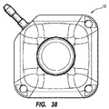
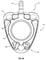
[0090]図2は本開示に従うアクセスポート10の別の実施形態の斜視図を示す。図2に示されるように、アクセスポート10の外部は、概して平行四辺形の形状の上面(図1A及び1Bに示される基準面9にて配置される)に、概して角錐的に伸長する、概して平行四辺形の形状のベース(図1A及び1Bに示される基準面11にて配置される)によって、実質的に画定される。図2に示されるように、角部42は、図1Aに示される角部32よりも大きくあり得る。さらに、図2に示されるアクセスポート10の上部トポグラフィー61は、図1Aに示される丸角領域30よりも大きい丸角領域40を含み得る。したがって、図2は、図1A及び1Bに示されるアクセスポート10から知覚可能的に区別可能であり得る、アクセスポート10の例示的実施形態を示す。例えば、本開示によって企図されるアクセスポートのある外部と、本開示によって企図される異なるアクセスポートの別の外部との間の差異は、触診によって判定され得る。
[0090] FIG. 2 shows a perspective view of another embodiment of an
[0091]別の実施形態では、本開示によって企図される別の態様において、アクセスポートの少なくとも1つの特徴を知覚するために型板が用いられ得る。例えば、アクセスポートが型板の形状に整合する又は実質的に対応するかどうかを判定するために、相補的形状の型板が、本開示によって企図されるアクセスポートを覆いそれに当接して配置され得る。かかるプロセスは、本開示によって企図されるアクセスポートの少なくとも1つの特徴を確実に示し又は知覚し得る。当然のことながら、アクセスポートの異なるモデルに対応する複数の型板が、その少なくとも1つの特徴を知覚するために、未知のアクセスポートに連続的に係合され得る。かかるプロセスは、本開示によって企図されるアクセスポートの(例えばモデル又は製造業者の)識別を可能にし得る。 [0091] In another embodiment, in another aspect contemplated by the present disclosure, a template may be used to perceive at least one feature of the access port. For example, a complementary shaped template is placed over and abutting the access port contemplated by the present disclosure to determine whether the access port matches or substantially corresponds to the shape of the template. obtain. Such a process may reliably indicate or perceive at least one characteristic of an access port contemplated by the present disclosure. Of course, a plurality of templates corresponding to different models of access ports can be successively engaged with an unknown access port to perceive at least one feature thereof. Such a process may allow identification (eg, model or manufacturer) of an access port contemplated by the present disclosure.
[0092]本開示によって企図される別の態様では、アクセスポートの上部トポグラフィーは、アクセスポートを識別するための少なくとも1つの特徴を含み得る。例えば、図3に示されるように、アクセスポート10の上面60は非平面であり得る。より具体的には、上面60は、放射状に内向きにセプタム18に向かって伸長するため、先細りであり得るか又は弓状に下向きに(すなわち図1A及び1Bに示される基準面11に向かって)伸長し得る。別の方法では、図3に示されるアクセスポート10は、実質的に、図1A及び1Bを参照して本明細書で上述した通りに構成され得る。したがって、上面60は、本開示によって企図されるアクセスポートの識別のための少なくとも1つの知覚可能な特徴の例示的一実施例である。
[0092] In another aspect contemplated by this disclosure, the top topography of the access port may include at least one feature for identifying the access port. For example, as shown in FIG. 3, the
[0093]本開示によって企図されるアクセスポートのなおもさらなる実施形態では、丸角領域30間に伸長する側領域54は、少なくとも1つの知覚可能な特徴を示し得る。例えば、図4に示すように、アクセスポート10は、隣接する丸角領域30間に弓状に伸長する1つ以上の側領域54を含み得る。別の方法では、図4に示されるアクセスポート10は、実質的に、図1A及び1Bを参照して本明細書で上述した通りに構成され得る。側領域54は、互いに対して合同若しくは対称であり得、又は、別の実施形態では、限定なしに、互いに対して異なるように構成され得る。
[0093] In still further embodiments of access ports contemplated by the present disclosure, the
[0094]図5は、本開示によって企図されるアクセスポートのさらなる例示的実施形態を示す。より具体的には、アクセスポート10は、図5に示すように、隣接する丸角領域30間に陥凹領域72を形成する、側領域54を含む。言い換えれば、上部トポグラフィー61は、概してセプタム18の周辺の周囲に配置された交互の陥凹領域72及び突出領域70を含み得る。別の方法では、図5に示されるアクセスポート10は、実質的に、図1A及び1Bを参照して本明細書で上述した通りに構成され得る。かかる構成は、少なくとも1つ以上の識別可能な特徴を有するアクセスポートを提供し得る。
[0094] FIG. 5 illustrates a further exemplary embodiment of an access port contemplated by the present disclosure. More specifically, the
[0095]本開示によって企図されるアクセスポートのさらなる実施形態では、図6A及び6Bは、概して図5を参照して記載されるように構成されるが、細長い本体20Eを有する、アクセスポート10の、それぞれ斜視図及び側面図を示す。より具体的には、図6A及び6Bに示されるアクセスポート10の細長い本体20Eは、概して上部トポグラフィー61から下向き(すなわち図1A及び1Bに示される基準面11に向かって)に伸長し、他方の側表面50とは異なる勾配(例えばセプタム18の上面に対して垂直な垂直軸に対する角度)を有する、側表面50Eを含む。別の方法では、図6に示されるアクセスポート10は、実質的に、図1A及び1Bを参照して本明細書で上述した通りに構成され得る。かかる構成は、細長い側部を有するアクセスポート10の細長い本体20Eを提供し得る。
[0095] In a further embodiment of an access port contemplated by the present disclosure, FIGS. 6A and 6B are generally configured as described with reference to FIG. 5, but of an
[0096]当然のことながら、本開示に従うアクセスポートの1つ以上の側表面は、所望であり得るように選択された形状を示す本体を形成するために構成され得る。本開示によって企図されるアクセスポートの細長い本体部は、本明細書で上述した他の特徴との組み合わせで、又は別の実施形態では単独で、本開示に従うアクセスポートの識別のための少なくとも1つの知覚可能な特徴を形成し得る。 [0096] It will be appreciated that one or more side surfaces of an access port according to the present disclosure may be configured to form a body exhibiting a selected shape as may be desired. An elongated body portion of an access port contemplated by the present disclosure is at least one for identification of an access port according to the present disclosure, in combination with other features described herein above, or alone in another embodiment. Perceptible features can be formed.
[0097]図7は、本開示によって包含されるアクセスポートのさらなる実施形態を示す。具体的には、図7に示されるように、アクセスポート10は、上部本体部20a及び下部本体部20bを含み得る。さらに、上部本体部20a及び下部本体部20bのそれぞれは、本体部20a及び20bが互いに対して垂直に積み重ねられ、部分的角錐形状(すなわち錐台)を示し得る。結果的に、上部本体部20aは、アクセスポート10の周辺に沿って伸長する、張り出したリム特徴76を形成し得る。さらに説明すると、上部本体部20aが側表面50a、丸角領域30a、及び上部トポグラフィー61によって実質的に画定される外部を有し得る一方で、下部本体部20bは、側表面50b及び丸角領域30bによって実質的に画定される外部を有し得る。張り出したリム特徴76は、触診を介した知覚のために寸法決定及び構成され得るということが理解され得る。かかる構成は、有益な物質又は医薬物質の送達のために、埋め込み後に識別可能な(例えばモデル番号、製造業者等によって)、好適なアクセスポートを提供し得る。
[0097] FIG. 7 illustrates a further embodiment of an access port encompassed by the present disclosure. Specifically, as shown in FIG. 7, the
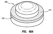
[0098]本開示は、本質的に平行四辺形でない外部形状を有するアクセスポートを企図するということが理解されるべきである。むしろ、本開示は、アクセスポートが、概して円柱形、概して円錐形、概して楕円形、概して長円形である外部、又は他の方法で本質的に弓状である外部を有し得るということを企図する。具体的には、本開示は、実質的に丸い又は弓状の外部を有するアクセスポートが、埋め込み後のアクセスポートの識別のために構成された少なくとも1つの特徴を含み得るということを企図する。例えば、図8に示されるように、実質的に円錐形である外面78を示すキャップ14を示す。キャップ14は、概して図1〜7を参照して記載されたアクセスポート10を形成するために、本明細書で上述のようにセプタム(図示せず)を捕捉するための好適なベース(図示せず)へと組み立てられ得る。
[0098] It should be understood that the present disclosure contemplates an access port having an external shape that is not essentially a parallelogram. Rather, the present disclosure contemplates that the access port may have an exterior that is generally cylindrical, generally conical, generally elliptical, generally oval, or otherwise arcuately arcuate. To do. Specifically, the present disclosure contemplates that an access port having a substantially round or arcuate exterior may include at least one feature configured for identification of the access port after implantation. For example, as shown in FIG. 8, a
[0099]本開示は、少なくとも1つの突出部、突出領域、陥凹部、陥凹領域、うねり、又は異なる高度の隣接特徴が、本開示によって企図されるアクセスポートを識別するための特徴を含み得るということをさらに企図する。より具体的には、図8に示される上部トポグラフィー61Cは、複数の突出部80を含み得る。突出部80は、キャップ14の下部部分へ移行する部分的球形の上面を示し得る。さらに詳細には、突出部80は、所望であり得るようにセプタム(図示せず)の周辺の周囲に、円周方向に離間配置され得る。一実施形態では、複数の突出部80は、セプタム(図示せず)の周辺の周囲に対称的に円周方向に離間配置され得る。より一般的には、少なくとも1つの突出部80は、アクセスポートの少なくとも1つの識別可能な特徴を形成するために、寸法決定、構成、及び配置され得る。当然のことながら、少なくとも1つの突出部80は、アクセスポートが埋め込まれる患者の快適性を促進するために構造され得る。理解され得るように、少なくとも1つの突出部80又は1つを超える突出部80が、本開示によって企図されるアクセスポート(図示せず)の上部トポグラフィー61C内に含まれ得る。
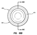
[0099] The present disclosure may include features for identifying an access port where at least one protrusion, protrusion region, recess, recess region, undulation, or different high degree of adjacent features is contemplated by the present disclosure. I will further contemplate that. More specifically, the
[0100]図9は、本開示によって企図されるアクセスポートを、患者内のその埋め込み後に形成及び識別するための、少なくとも1つの突出部80Eを含むキャップ14の別の実施形態を示す。突出部80Eは、回転中心を中心として円周方向に伸長し得る。したがって、突出部80Eは、丸端83間に円周方向に伸長する本体87を示し得る。さらに、キャップ14は、回転軸を中心として実質的に対称である外面78を有し得る。より一般的には、本体20は、キャップ14の下部範囲71にて配置される、概して円形、概して楕円形、又は概して長円形のベースから、ベースの断面よりも小さく、キャップ14の上部範囲73にて配置される(突出部80Eを考慮せず)、上部の概して円形、概して楕円形、又は概して長円形の断面へ伸長し得る。さらに、図9に示される側表面51は、ベースとキャップ14の上部トポグラフィー61との間に弓状に伸長する。側表面51は、概して先細り又は円錐様式で伸長し得るか、角部形状又は他の弓状形状を示し得るか、又は別の方法でアクセスポートのベースの断面とその上部トポグラフィー61Cに近接する断面との間を移行し得る。
[0100] FIG. 9 illustrates another embodiment of a
[0101]さらに、図10は、本開示によって企図されるアクセスポートを形成するための、交互に円周方向に伸長する突出部80E及び円周方向に伸長する陥凹部82を含む上部トポグラフィー61Cを有する、キャップ14の一実施形態を示し、この円周方向に伸長する突出部80Eは、円周方向に伸長する陥凹部80Eよりも円周方向に大きい。本開示によって企図されるアクセスポートの別の実施形態では、図11は、交互に円周方向に伸長する突出部80E及び円周方向に伸長する陥凹部82を含む上部トポグラフィー61Cを有する、キャップ14の斜視図を示し、この円周方向に伸長する突出部80E及び円周方向に伸長する陥凹部82は、(円周方向の)寸法又は範囲において実質的に同等である。本開示によって企図されるアクセスポートを形成するためのなおもさらなるキャップ14の実施形態では、図12は、3つの円周方向に伸長する突出部80E及び3つの円周方向に伸長する陥凹部82を含み、円周方向に交互になるように配置された上部トポグラフィー61Cを有するキャップ14の斜視図を示し、この円周方向に伸長する突出部80E及び円周方向に伸長する陥凹部82は、寸法において(円周方向に)実質的に同等である。
[0101] Further, FIG. 10 shows an
[0102]図13は、本開示によって企図されるアクセスポートを形成するための、円周方向に伸長する突出部80T及び円周方向に伸長する陥凹部82Tを含む上部トポグラフィー61Cを含む、キャップ14の追加の実施形態の斜視図であり、ここで移行領域81が円周方向に伸長する突出部80Tと円周方向に伸長する陥凹部82Tとの間に提供される。かかる移行領域81は、図13に示されるように、先細りし得るか、又は円周方向に伸長する突出部80Tと円周方向に伸長する陥凹部82Tとの間を滑らかに移行し得る。さらに、図14は本開示によって企図されるアクセスポートを形成するための、互いの間を移行し、上部トポグラフィー61Cを含むうねりトポグラフィーを形成するために円周方向に交互になる、突出部領域96及び陥凹領域98を含む上部トポグラフィー61Cを含む、キャップ14の追加の実施形態の斜視図を示す。かかるうねりトポグラフィーは、図14に示されるように、概して円周方向に隣接する突出部領域96と陥凹領域98との間を滑らかに移行する。
[0102] FIG. 13 shows a cap including an
[0103]本開示によって企図されるアクセスポートのさらなる実施形態では、図15A及び15Bは、概して図5を参照して記載されるように構成されるが、少なくとも1つの非平面側表面を含み得る、アクセスポート10の、それぞれ斜視図及び上面正面図を示す。別の実施形態では、図15に示されるアクセスポート10は、図1〜4若しくは図6〜7、又は、限定なしに、本明細書の以下で記載される任意の実施形態において示されるように、構成され得る。より具体的には、アクセスポート10の細長い本体20は、図15A及び15Bに示されるように、弓状に伸長する3つの側表面50Rを含む(図15Bに示される通り)。かかる構成は、埋め込み後に識別可能なアクセスポート10を提供し得る。本開示によって企図されるアクセスポートのなおも別の実施形態では、図16は、アクセスポート10の側表面50間に形成された角部32の一部を切断する側壁100を含む、アクセスポート10の斜視図を示す。かかるアクセスポート10は、単独で又は少なくとも1つの他の特徴との組み合わせで、本開示によって企図されるアクセスポートの少なくとも1つの識別可能な特徴を含む、3つの縫合開孔部66を含み得るということにもまた注目され得る。さらに、図16に示されるように、排出口ステム31は、側壁100から伸長し得る。
[0103] In a further embodiment of an access port contemplated by the present disclosure, FIGS. 15A and 15B are generally configured as described with reference to FIG. 5, but may include at least one non-planar surface. The
[0104]本開示によって企図されるアクセスポートのさらなる実施形態では、図17は、アクセスポート10の斜視図を示し、ここでキャップ14及びベース16は、噛合線15に沿って互いに組み立てられると、アクセスポート10の周辺の少なくとも一部分の周囲に伸長する、フランジ特徴又はリップ特徴102を形成する。図17に示されるように、リップ特徴102は、アクセスポート10の周辺の実質的周囲に、キャップ14とベース16との間の噛合線15に近接して伸長する。かかる特徴は、本開示によって企図されるアクセスポートの、少なくとも1つの識別可能な特徴を含み得る。したがって、キャップ14とベース16との間の周辺の不連続性が、概してそれらの間の噛合線15に沿って形成され得るということが理解され得る。図7に示されるアクセスポートの実施形態では、張り出したリム特徴76は周辺の不連続性を含み得、又は、図17に示されるアクセスポートの実施形態では、リップ特徴102は周辺の不連続性を含み得る。
[0104] In a further embodiment of an access port contemplated by the present disclosure, FIG. 17 shows a perspective view of the
[0105]本開示によって企図されるアクセスポートのさらなる実施形態では、図18は、アクセスポート10の斜視図を示し、ここで少なくとも1つの側表面50の少なくとも一部分が凹面である。図18に示されるように、側表面50の凹面領域106は凹面である。凹面(すなわち凹面領域106)は、限定なしに、本明細書に示される実施形態のうちの任意のもののアクセスポートの側表面の少なくとも一部分にわたって示され得る。したがって、本開示によって企図されるアクセスポートの、凹面である少なくともその一部分を少なくとも有する、少なくとも1つの側表面50は、本開示によって企図されるアクセスポートの識別のための少なくとも1つの知覚可能な特徴の例示的一実施例である。
[0105] In a further embodiment of an access port contemplated by the present disclosure, FIG. 18 shows a perspective view of the
[0106]本開示によって企図されるアクセスポートのさらなる実施形態では、図18はアクセスポート10の斜視図を示し、ここで少なくとも1つの側表面50の少なくとも一部分が凹面である。図18に示されるように、側表面50の領域106は凹面である。凹面は、限定なしに、本明細書に示される実施形態のうちの任意のもののアクセスポートの側表面の少なくとも一部分にわたって示され得る。したがって、本開示によって企図されるアクセスポートの、凹面である少なくともその一部分を少なくとも有する、少なくとも1つの側表面50は、本開示によって企図されるアクセスポートの識別のための少なくとも1つの知覚可能な特徴の例示的一実施例である。
[0106] In a further embodiment of an access port contemplated by the present disclosure, FIG. 18 shows a perspective view of the
[0107]本開示によって企図されるアクセスポートのさらなる実施形態では、図19は、概して図6A及び6Bを参照して記載されるように構成されるアクセスポート10の斜視図を示す。より具体的には、図19に示される細長い本体20ERは、アクセスポート10の上部トポグラフィー61から下向きに(すなわち図1A及び1Bに示される基準面11に向かって)弓状に伸長する、側表面50ERを含む。かかる構成は、細長い側部を有するアクセスポート10の細長い本体20Eを提供し得る。
[0107] In a further embodiment of an access port contemplated by the present disclosure, FIG. 19 shows a perspective view of an
[0108]本開示によって企図されるアクセスポートの上述の様々な実施形態から、多くの変化形、追加、又は異なる特徴が本開示に包含され得るということが理解されるべきである。したがって、本開示はいくつかの上述の例示的実施形態に限定されない。 [0108] It should be understood that many variations, additions, or different features may be included in the present disclosure from the various embodiments described above of access ports contemplated by the present disclosure. Accordingly, the present disclosure is not limited to some of the above-described exemplary embodiments.
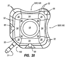
[0109]例えば、本開示によって企図されるアクセスポート10の上面正面図を示す図20に示されるように、アクセスポート10は、側表面50間の角部32、側壁100から伸長する排出口ステム31、並びに凹面領域106及び弓状表面50Rのうちの少なくとも1つを少なくとも部分的に切断する、側壁100を含み得る。さらに、図20に示されるように、縫合開孔部66は、皮下埋め込みの後でアクセスポート10を識別するために配置され得る。
[0109] For example, as shown in FIG. 20 which shows a top front view of the
[0110]さらに、本開示は、本質的に多角形である外部形状を有するアクセスポートを企図する。具体的には、本開示は、本開示によって企図されるアクセスポートが概して三角形の外部を示し得るということを企図する。したがって、図21に示すように、本体20は、概して角錐又は先細りの形状(すなわち多角形のそれぞれの辺に共通の頂点に向かって伸長する表面を有する多角形のベース)を示し得る。概して、アクセスポート10の本体20Tは、概して三角形の形状の底面と、相対的に小さく概して三角形の形状の上部ベースとの間に、伸長し得る。結果的に、アクセスポート10の外部は、その間に伸長する角部32を有する3つの側表面(例えば50、50R、102、50E)によって実質的に画定され得る。さらに、アクセスポート10の上部トポグラフィー61は、側領域54及び丸角領域30との組み合わせで、上面60によって画定され得る。かかる構造は、触診によって知覚され得る少なくとも1つの特徴を有するアクセスポートを提供し得る。
[0110] Furthermore, the present disclosure contemplates an access port having an external shape that is essentially polygonal. In particular, this disclosure contemplates that the access ports contemplated by the present disclosure may exhibit a generally triangular exterior. Thus, as shown in FIG. 21, the
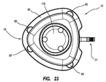
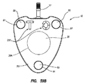
[0111]図22及び23は、概して三角形の外部形状を含むアクセスポートの別の実施形態の斜視図及び上面正面図を示す。より具体的には、図22及び23に示されるように、キャップ14及びベース16(集合的にハウジングを形成する)は、アクセスポート10を形成するためにセプタム118を捕捉し得る。さらに、排出口ステム31は、ベース16内で形成された排出口陥凹部93内に配置及び密閉され得る、ステムベースを含み得る。排出口ステム31は、アクセスポート10内に形成された腔と流体連通し得る。任意追加的に、縫合プラグ89がベース16において形成された縫合腔91内に配置され得る。縫合プラグ89は、アクセスポート10(すなわちベース16)を患者に結合する縫合間のいくらかの弾性を提供し得る、柔軟な材料(例えば、シリコーン、ゴム等)を含み得る。さらに詳細には、アクセスポート10の側周辺95(例えば1つ以上の側壁)は、概して三角形であり得る。したがって、キャップ14及びベース16は、アクセスポート10の概して三角形のハウジング又は本体を集合的に形成し得る。さらに、本開示は、側周辺95が、キャップ14の上面161とベース16の下部表面151との間の断面寸法において、増加又は減少し得る(先細り又は弓状に変形することによって)ということを企図する。図22及び23に示されるように、アクセスポート10の横断面(ベース16の下部表面151に実質的に平行な選択された面において取られる)は、ベース16の下部表面151に近接するとより大きくあり得、キャップ14の上面161に近接すると相対的により小さくあり得る。
[0111] FIGS. 22 and 23 show perspective and top front views of another embodiment of an access port that includes a generally triangular outer shape. More specifically, as shown in FIGS. 22 and 23,
[0112]さらに、図24は、アクセスポート10の横断面の簡略表示を示す。図24に示されるように、アクセスポート10の側周辺95は、関連する頂点領域101間に伸長する3つの側領域103を画定し得る。さらに、一実施形態では、そして図24に示されるように、側周辺95は、実質的に等辺の概して三角形の形状を画定し得る。当業者であれば理解するであろうが、側領域103は、関連する頂点領域101間に弓状に伸長し得、したがって、側領域103は概して三角形の形状の「辺」を形成し得る。さらに、頂点領域101は丸いが、かかる頂点領域101は、隣接する側領域103間の交点を形成するということが理解され得る。結果的に、当業者であれば、本明細書で使用される句「概して三角形」は、限定なしに、隣接する辺が交わる任意の概して3辺の形状を包含するということを理解するであろう。例えば、句「概して三角形」は、限定なしに、3辺多角形、円弧三角形、正三角形等を包含する。
[0112] Further, FIG. 24 shows a simplified representation of a cross section of the
[0113]本開示は、本開示によって企図されるアクセスポートの少なくとも1つの特徴は、視覚的又は触診によって観測可能でないことがあり得るが、むしろ別の方法で観測可能であり得るということもまた企図している。例えば、本開示は、アクセスポートの少なくとも1つの特徴が、X線又は超音波等の画像技術との相互作用を通して観測可能であり得るということを企図する。例えば、一実施形態では、金属特徴(例えば平板又は他の金属形状)が、本開示によって企図されるアクセスポートによって含まれ得る。理解され得るように、かかる金属特徴は、同時にX線感光膜をアクセスポートを通過するX線エネルギーに曝露させる一方で、アクセスポートのX線エネルギーへの曝露によって生成される、X線写真上で表され得る。さらに、本開示は、アクセスポートの金属特徴の、寸法、形状、又は寸法及び形状の両方が、アクセスポートの識別を強化するために構成され得るということを企図する。例えば、金属特徴が金属平板を含むと仮定すると、寸法、形状、又は両方が、アクセスポートの識別のために選択的に仕立てられ得る。同様に、本開示によって企図されるアクセスポートの特徴は、超音波相互作用を介した検出のために仕立てられ得る。かかる特徴は、外部トポグラフィー特徴を含み得る。別の実施形態では、かかる特徴は、超音波画像によって識別され得る接合表面を形成する2つ以上の材料を含む、複合材料構造体を含み得る。 [0113] The present disclosure also indicates that at least one feature of an access port contemplated by the present disclosure may not be observable visually or by palpation, but rather may be observable otherwise. I am planning. For example, the present disclosure contemplates that at least one feature of the access port may be observable through interaction with imaging techniques such as X-rays or ultrasound. For example, in one embodiment, a metal feature (eg, a flat plate or other metal shape) may be included by an access port contemplated by the present disclosure. As can be appreciated, such metal features can be seen on radiographs produced by exposure of the access port to x-ray energy while simultaneously exposing the x-ray sensitive film to x-ray energy passing through the access port. Can be represented. Furthermore, the present disclosure contemplates that the size, shape, or both the size and shape of the access port metal features may be configured to enhance access port identification. For example, assuming that the metal feature includes a metal plate, the size, shape, or both can be tailored selectively for access port identification. Similarly, access port features contemplated by the present disclosure can be tailored for detection via ultrasound interaction. Such features can include external topographic features. In another embodiment, such a feature can include a composite structure that includes two or more materials that form a bonding surface that can be identified by an ultrasound image.
[0114]本開示によって企図される画像技術との相互作用によって観測可能な特徴の実施形態の一実施例は、図52、53A、及び53Bに示される。図52は、アクセスポート10の底面斜視図を描写する。図53Bはアクセスポートの底面図を示す一方で、図53Aは、アクセスポート10の上面図を示す。図52、53A、及び53Bのアクセスポート10は、図22及び23において見られるアクセスポート10に、本体を画定するために協働するキャップ14及びベース16を含む、いくつかの点で類似する。しかしながら、本実施形態の実施例では、図52及び53Bに見られるように、ベース16の下部表面151は、識別特徴200を含む。識別特徴200は、描写される「CT」等の、1つ以上の英数字であり得るということが企図される。さらに、本開示は、1つ以上の記号、模様、文字、デザイン、それらの組み合わせ等のような、他のマーキングの使用を企図する。識別特徴200は、識別特徴を、アクセスポートの1つ以上の様々な特徴の特定の識別用に仕立てるために、任意の寸法、形状、又は両方であり得る。具体的には、一実施形態では、識別特徴200は、埋め込みアクセスポートの高圧注入可能性に関して施術者に情報を伝達し得る。他の実施形態では、下記に記載されるように、識別特徴が他の方法で画定され得る一方で、本実施形態では、識別特徴200は陥凹特徴として画定されるということに注目されたい。
[0114] An example of an embodiment of features observable by interaction with imaging techniques contemplated by the present disclosure is shown in FIGS. 52, 53A, and 53B. FIG. 52 depicts a bottom perspective view of the
[0115]上述のように、図53Aは、アクセスポート10の上面図を描写する。識別特徴200は、画像技術との相互作用なしでは、キャップ14の上面161を通して又はセプタム118を通して観測可能ではないということに注目されたい。図53Bに見られるように、識別特徴200の英数字「CT」は、ベース16の下部表面151上に左右反転して彫刻される。皮下埋め込みアクセスポートを識別するためにX線画像等の画像技術が使用されると、「CT」が好適な配向で可視的になるように、「CT」は左右反転して彫刻される。アクセスポートの底表面上に左右反転させた所望の識別特徴を彫刻することによって、施術者は、埋め込み後にポートに、アクセスポートが患者の体内にある間に裏返しになったか又は別の方法で誤った配向になったかどうか等の、問題があるかどうかを判定することができるようになる。したがって、識別特徴がX線画像において左右反転又は斜めに見える場合、施術者は、アクセスポートの使用が試見られる前に問題を是正することができる。
[0115] As described above, FIG. 53A depicts a top view of the
[0116]ポートの一部分のみが金属性材料、例えば金属平板、を含むアクセスポートにおいてもまた有益であるが、彫刻技術は、チタン、ステンレス鋼、又は典型的に放射線不透過性、すなわち十分な厚さにおいてX線に対し非透過性である他の材料等の、固体金属から組成されるアクセスポートについての一実施形態においてよく適している。図54A〜54Cは、患者への埋め込み後のX線画像によって見られる、チタン又は他の金属性材料を含む、図52のアクセスポート10を表す画像である。アクセスポート10は、図52及び53Bにおいて見られる識別特徴200を含む。アクセスポート10の相対的な厚さのため、流体腔である腔36の腔周辺36Aを取り囲むベース16及びキャップ14の材料は、X線に対して実質的に非透過性であり、そのため図54AのX線画像において相対的に暗く見える。しかしながら、腔周辺36A内のアクセスポート10の材料は、腔ベース220(図55において見られる)を通して、キャップ14及びベース16の材料を通してよりも相対的に薄い。したがって、識別特徴200を作り出すときに材料をさらに薄くすることで、X線画像下で、腔ベースの取り囲む材料よりも識別特徴を相対的に放射線画像的に透過性に見せることが可能になる。図54Aにおける識別特徴200は、適切な配向で可視的であり、アクセスポートが裏返しになっていないことを示すということに注目されたい。
[0116] Engraving techniques are also useful in access ports where only a portion of the port includes a metallic material, such as a metal plate, but titanium, stainless steel, or typically radiopaque, ie sufficient thickness It is well suited in one embodiment for an access port composed of solid metal, such as other materials that are opaque to X-rays. 54A-54C are images representing the
[0117]図54B及び54Cは、アクセスポート10の識別特徴200を表すさらなるX線画像であり、このアクセスポートは、それぞれ約20及び50度の角度で傾いている。したがって、識別特徴200は、埋め込み後のアクセスポート10の相対的配向を判定するためにもまた有用である。
[0117] FIGS. 54B and 54C are additional X-ray images representing the identification features 200 of the
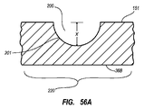
[0118]図55は、図52における線55〜55にて取られたアクセスポート10の断面図を示す。この実施形態の実施例では、識別特徴200は、セプタム118及び腔36の下に配置される。図56A及び56Bは、陥凹識別特徴200の潜在的切断輪郭の拡大断面図をさらに描写する。図56Aは、ベース16の下部表面151上に彫刻され、美的目的及び製造の容易性のために使用される、丸い彫刻輪郭201を示す。しかしながら、画像技術下での相対的により画定されたコントラストのために、図56Bに見られるように、縁の鋭い彫刻輪郭202が使用され得る。多様な断面陥凹輪郭が用いられ得るということに注目されたい。本開示は、ここでは彫刻が述べられるものの、識別特徴をマーキングするための、粉砕、機械加工、化学又はレーザーエッチング、鋳造、鍛造等のような、他の方法が使用され得るということをさらに企図する。
[0118] FIG. 55 shows a cross-sectional view of the
[0119]使用される切断輪郭に関係なく、概して彫刻深さXが大きいほど、よりよいコントラストが達成される。しかしながら、最適彫刻深さXは、図55に示すように、腔36の真下の、ベースの一部分である腔ベース220全体の厚さに依存する。例えば、チタンを含むアクセスポートの一実施形態では、腔ベース220の全体の厚さが約0.051センチメートル(0.020インチ)である場合、X線画像目的のための十分なコントラストは、一実施形態において、約0.02センチメートル〜約0.28(0.009インチ〜約0.011インチ)の間の深さX(図56A、56B)まで識別特徴200を彫刻することによって得ることができる。腔ベース220の全体の厚さが約0.076センチメートル(0.030インチ)である、チタンを含むアクセスポートの別の実施形態の実施例では、十分なコントラストは、識別特徴200を、約0.038センチメートル〜約0.053センチメートル(0.015インチ〜約0.021インチ)の間の深さXまで彫刻することによって得ることができる。当業者であれば、製品の安全性要求に準拠し、依然として本開示によって企図される範囲内に留まるために、彫刻特徴の深さが大いに多様であり得るということを理解するであろう。さらに、識別特徴の深さXは、アクセスポート上の特徴の位置、画像技術によって穿通される材料の厚さ、アクセスポートに含まれる材料の種類等に従って多様であり得る。
[0119] Regardless of the cutting contour used, generally the greater the engraving depth X, the better the contrast is achieved. However, the optimum engraving depth X depends on the thickness of the
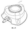
[0120]金属性又は他の放射線不透過性アクセスポートにおける識別特徴の使用は、例えば図57A〜58Cに見られるような、多様な可能な構成を有するアクセスポートに適用され得るということもまた、本開示によって企図される。図57A〜57Cは、一実施形態を描写し、このアクセスポート10は、ベース又は本体116の下部表面251上に識別特徴200を含む。図57A〜57Cにおけるアクセスポート10は、腔36をわたってセプタム118をベース又は本体116に密閉する、保持リング230を含む。一実施形態では、保持リング230は、セプタム118を定位置に保持するために、ベース又は本体116へ圧入される。図58A〜58Cは、さらに別の実施形態を示し、このアクセスポート10は、腔ベース220上に識別特徴200を含み、腔ベースは本体を画定するために、キャップ114の下部表面252と噛合され同一表面となる。他の噛合構成もまた用いられ得るが、特定の実施形態では、腔ベース220はキャップ114に圧入される。
[0120] It is also noted that the use of identification features in metallic or other radiopaque access ports can be applied to access ports having a variety of possible configurations, as seen, for example, in FIGS. 57A-58C. Contemplated by the present disclosure. 57A-57C depict one embodiment, the
[0121]本開示によって企図される別の実施形態では、図59A及び59Bは、識別特徴200の位置もまた多様であり得るということを示す。識別特徴200を腔36の下に配置するのではなく、識別特徴を、排出口ステム31の下でかつセプタムプラグ89間、すなわちアクセスポート底表面の外周付近等の、アクセスポート10の別の部分の下に配置することが可能である。識別特徴200の上のアクセスポート構造体の全体の厚さが、腔36の下で彫刻されるよりもこの位置での方が大きいものの、位置における変化は、相対的により深い彫刻を可能にし、腔ベース220を過剰に薄くすることの危険性なくコントラストを増加させる。さらに、一実施形態では、彫刻が垂直に整列するように底表面及び上表面の両方に彫刻することによって識別特徴を複合的に画定することが可能である。これは、識別特徴を通る相対的により大きい放射線画像の透過性を提供するために、残っている材料の厚さを大いに減らすことを可能にする。
[0121] In another embodiment contemplated by the present disclosure, FIGS. 59A and 59B illustrate that the location of the
[0122]さらに、本開示は、高圧注入可能性又はアクセスポートの他の態様又は特徴を示すための、任意の多様な所望の識別特徴又はその組み合わせを有する、アクセスポートを企図する。具体的には、図60A〜61Bは、実施形態の実施例に従う、識別特徴200の異なる種類を描写する。図60A〜60Bは、記号識別特徴200を描写する。図61A〜61Bは、識別特徴200、すなわち英数字識別特徴200Aと模様識別特徴200Bとの組み合わせを含む、アクセスポート10の例示的実施例を描写する。模様又は記号識別特徴は、配向を示す役に立つため又は任意の他の所望の理由のためにもまた使用され得る。本開示によって、他の記号、模様、マーク、及び英数字が、単独及び互いとの任意の組み合わせで、多様なアクセスポート構成において使用され得るということが理解される。
[0122] Further, the present disclosure contemplates an access port having any of a variety of desired identifying features or combinations thereof to indicate high pressure injectability or other aspects or features of the access port. Specifically, FIGS. 60A-61B depict different types of identification features 200, according to example implementations. 60A-60B depict a
[0123]追加の実施形態では、識別特徴は、アクセスポート10の腔36の内部底表面36B上で、又は底表面251上に提供される識別特徴200に加えて、画定され得る。別の実施形態では、所望の放射線不透過性の、英数字、記号、模様等の画定縁を取り囲む材料は、識別特徴の「ポジティブ」レリーフ画像を画定するために、識別特徴の所望の特徴形状自体を取り除く代わりに取り除かれ得る。かかるポジティブレリーフの識別特徴は、例えばアクセスポート本体の下部表面上又は腔の内部底表面上で、画定され得る。
[0123] In additional embodiments, identification features may be defined on the inner bottom surface 36B of the
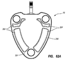
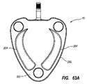
[0124]本開示によって企図される、様々な種類の記号、模様、マーク、及び英数字に加え、図62A〜63Cは、X線又は他の好適な画像技術を介して観測可能なアクセスポートの特徴を識別する、追加の実施形態の実施例を開示する。具体的には、本開示は、アクセスポート10の一部が空洞化している殻なし(shelled-out)腔204の使用を企図する。これは、ベース若しくは本体116の下部表面251、又は、図151におけるベース16の下部表面151、及び図58A〜58Cにおけるキャップ114の下部表面252を含む、本明細書に記載する他の実施形態の対応するポート下部表面から、内向きに伸長する殻なし腔204をもたらす。これは、腔周辺36A又はアクセスポート10の外部側表面250を分断することなく、腔36を取り囲む材料を取り除くことによってなされる。図62Bにおいて見られるように、リブ240は、アクセスポート10の残っている「殻つき(shelled)」枠を支持するために残され得る。かかる腔204の画定は、X線画像によって識別され得るアクセスポート10の放射線不透過性における相対的な差異を提供する。したがって、腔204は、模様を画定するため又はアクセスポート10の態様又は特徴の識別のための表示部を形成するために配置され得る。他の実施形態では、腔は、アクセスポートの上表面及び側表面を含む他の表面から伸長するように画定され得る。
[0124] In addition to the various types of symbols, patterns, marks, and alphanumeric characters contemplated by this disclosure, FIGS. 62A-63C illustrate access port observability via X-ray or other suitable imaging techniques. Examples of additional embodiments that identify features are disclosed. Specifically, the present disclosure contemplates the use of a shelled-
[0125]本開示によって企図されるさらなる態様では、情報が本開示によって企図されるアクセスポートによって含まれる、通信技術が利用され得るということが企図される。概して、通信装置(例えば、ラジオビーコン、発光素子、超音波放出トランスデューサ等)が、本開示によって企図されるアクセスポートにはめ込まれるか又は別の方法で付属され得る。かかる通信装置は、所与の刺激に反応して情報を送信するために構成され得る。より具体的には、本開示は、本開示によって企図されるアクセスポートが要求信号(例えば、音、衝撃若しくは加速、光、電波等)に曝露し得るということを企図する。かかる要求信号は、通信装置が、音、光、電波によって、又は当該技術分野において既知の別の方法で、そこから情報を送信することを引き起こし得る。かかる情報は、本開示によって企図されるアクセスポートを識別するために用いられ得る。 [0125] In a further aspect contemplated by this disclosure, it is contemplated that communication techniques may be utilized in which information is included by an access port contemplated by this disclosure. In general, a communication device (eg, radio beacon, light emitting element, ultrasound emitting transducer, etc.) may be fitted or otherwise attached to an access port contemplated by the present disclosure. Such a communication device can be configured to transmit information in response to a given stimulus. More specifically, the present disclosure contemplates that an access port contemplated by the present disclosure may be exposed to a request signal (eg, sound, shock or acceleration, light, radio waves, etc.). Such a request signal may cause the communication device to transmit information therefrom by sound, light, radio waves, or in other ways known in the art. Such information can be used to identify an access port contemplated by the present disclosure.
[0126]1つの例示的実施例では、本開示によって企図されるアクセスポートの識別のために、無線周波数識別技術が用いられ得るということが企図される。特に、いわゆる能動型RFIDタグは、内部電池によって給電され、典型的に読み取り/書き込み装置である。現在は、好適な低電力回路に結合された好適な電池は、動作温度、並びに読み取り/書き込み周期、及び用途に依存し、10年以上の長きにわたって機能性を保証することができる。いわゆる受動型RFIDタグは、別個の外部の電力源を伴わずに動作し、読取り器から生成された動作電力を得る。受動型RFIDタグは、変更され得ない固有のデータセット(通常は32〜128ビット)で典型的にプログラム化される。読み取り専用タグは、選択された製品特有の情報を含み得る一次元バーコードに匹敵する、識別器として動作し得る。したがって、受動型RFIDタグは、能動型RFIDタグよりも非常に軽く、安価であり得、事実上無制限の動作寿命を提供し得る。トレードオフは、それらが能動型タグよりも短い読み取り範囲を有し、より多く給電された読取り器を要求するということである。 [0126] In one exemplary embodiment, it is contemplated that radio frequency identification techniques may be used for identification of access ports contemplated by the present disclosure. In particular, so-called active RFID tags are powered by internal batteries and are typically read / write devices. Currently, a suitable battery coupled to a suitable low power circuit can guarantee functionality for as long as 10 years or more, depending on the operating temperature and read / write cycle and application. So-called passive RFID tags operate without a separate external power source and obtain the operating power generated from the reader. Passive RFID tags are typically programmed with a unique data set (usually 32-128 bits) that cannot be modified. The read-only tag can act as a discriminator comparable to a one-dimensional barcode that can contain information specific to the selected product. Thus, passive RFID tags can be much lighter and less expensive than active RFID tags and can provide a virtually unlimited operating life. The trade-off is that they have a shorter reading range than active tags and require more powered readers.
[0127]RFIDアプローチの1つの利点は、該技術の、非接触、見通し外という性質である。タグは、雪、霧、氷、ペンキ、痂皮垢等の、様々な物質、並びに他の光学的読取り技術が有効性で劣り得る他の視覚的及び環境的に厳しい条件を通して、読み取られ得る。RFIDは、厳しい状況において急速な速度でもまた読み取られ得、ほとんどの場合、約100ミリ秒未満以内で反応する。 [0127] One advantage of the RFID approach is the non-contact, out-of-line nature of the technology. Tags can be read through a variety of materials, such as snow, fog, ice, paint, crust, and other visually and environmentally harsh conditions where other optical reading techniques can be less effective. RFID can also be read at rapid speeds in harsh situations and in most cases reacts in less than about 100 milliseconds.
[0128]次に、追加の実施形態を記載することにおいて、概して図64〜75Cを参照すると、このアクセスポートは、患者の体内への埋め込み後のアクセスポートの少なくとも1つの属性又は特徴の識別を促進するために、例えばX線及び蛍光法等の画像技術との相互作用によって観測可能な、少なくとも1つの識別特徴を、含む。記載される実施形態は、単独又は本明細書に記載される他の識別特徴と一緒に含まれ得、様々な寸法、形状、及び他の構成における多様性を有するアクセスポートと共に用いられ得るということが理解される。したがって、本明細書に記載される実施形態は、単に本開示の原理の実施例に過ぎない。 [0128] Next, in describing additional embodiments, referring generally to FIGS. 64-75C, this access port provides identification of at least one attribute or feature of the access port after implantation into the patient's body. To facilitate, it includes at least one distinguishing feature that is observable by interaction with imaging techniques such as X-ray and fluorescence techniques. The described embodiments can be included alone or in conjunction with other identifying features described herein and can be used with access ports having a variety of sizes, shapes, and variations in other configurations. Is understood. Accordingly, the embodiments described herein are merely examples of the principles of the present disclosure.
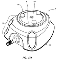
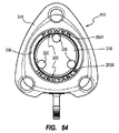
[0129]図64は、ベース316及びベースによって画定されるリザーバを覆うセプタム318を含む、アクセスポート310を示す。セプタム318は、アクセスポート310が皮下埋め込みされた後の、臨床医による、セプタムの外側デジタル触診及び位置特定を可能にするための、複数の触診こぶ320を含む。ポート310は、ポートリザーバの頂上の定位置にセプタム318を捕捉し、保持するための保持リング330を含む。他の実施形態では、他の好適な材料が使用され得るが、本実施形態では、ポートベース316及び保持リングの両方が、例えばチタンを含む金属性物質である。
[0129] FIG. 64 shows an
[0130]本実施形態では、保持リング330は、その埋め込み後に、ポート310の所定の属性又は特徴を識別するための、識別特徴200を含む。具体的には、保持リング330は、「高圧注入可能」と綴る英数字識別特徴200Aを含み、ポート310が高圧注入可能であるということを示す。一実施形態における英数字は、文字と周囲の金属性保持リング材料との間の相対的厚さ差異を提供するために、エッチング又は保持リング330において好適に画定された別の方法によって差し込まれ、したがって、ポート310がX線画像技術で撮像されると、対応する放射線画像コントラストを提供する。このコントラストは、英数字がX線において可視的かつゆえにX線を見ている臨床医によって認識可能となることを可能にし、したがって、識別特徴200に関連するポート属性又は特徴を確認することを可能にする。
[0130] In this embodiment, the retaining
[0131]英数字識別特徴200Aは、保持リング330上で、エッチング、彫刻等を含む、任意の数の好適な方法で画定され得、文字は保持リングを通して部分的に又は完全に画定され得る。さらに、使用される特定の文字又は語は、本明細書に記載されるものから変化し得る。実際に、他の文字、模様、記号等が、識別特徴200において用いられ得る。任意追加的に、識別特徴は、図64に示すようにネガティブレリーフで、又は所望であればポジティブレリーフで、画定され得る。
[0131] The
[0132]さらに、他の実施形態では、保持リングの識別特徴は、ポートの構成に従い他の方法で構成され得る。例えば、ポート本体が非金属性材料を含む実施形態では、識別特徴は、英数、若しくは他の文字、又は特徴を形成するために、特徴保持リングの表面に塗布された、放射線不透過性インクを含み得る。さらに他の実施形態では、識別特徴は、保持リングに加えポートの一部分又は表面上に含まれ得る。したがって、これらの及びその他の変更例が意図される。 [0132] Further, in other embodiments, the retaining ring identification feature may be configured in other ways according to the configuration of the port. For example, in embodiments where the port body includes a non-metallic material, the identifying feature is an alphanumeric or other letter or radiopaque ink applied to the surface of the feature retaining ring to form a feature. Can be included. In still other embodiments, the identification feature may be included on a portion or surface of the port in addition to the retaining ring. Accordingly, these and other modifications are contemplated.
[0133]図65は、別の実施形態に従い構成された金属性ポート310の金属性保持リング330を含み、この保持リングは、それぞれが、該保持リングによって保持されるセプタム318の一部分に重複する、複数の重複部分330Aを含む、識別特徴200を画定する。図65において、保持リング330の重複部分330Aは、保持リングの下の金属性ポート310の一部分に対する放射線画像のコントラストを提供する、概して三角形の形状を画定するために協働する。これまでのように、これは、ポート310がX線画像技術で画像化される際、対応する放射線画像のコントラストを提供し、所定のポート属性又は確認されるべき識別特徴200に関する特徴を確認するために、該三角形の形状が放射線不透過性の輪郭として臨床医によって認識可能となることを可能にする。他の実施形態では、保持リングは、本明細書に示される三角形の形状に加え他の形状を画定し得る。さらに、文字、記号、又は他の模様が、所望であれば、保持リングの重複部分に画定され得るか又はその上に含まれ得る。
[0133] FIG. 65 includes a
[0134]図66A〜66Dは、患者への埋め込み後に、アクセスポートの所定の属性又は特徴を識別するための、識別特徴の組み込みに関する様々な詳細を描写する。具体的には、これらの図は、ベース416に噛合可能なキャップ414及びキャップとベースとの間に挿入された2つのセプタム418を含む、二重リザーバアクセスポート410を描写する。縫合プラグ422はポート410に含まれる。本実施形態に従い、ポートベース416の底表面416Aは、皮下埋め込みポートの識別のための識別特徴200を含む。多数の他の異なる文字、模様、及び/又は組み合わせ構成が可能であるが、図66Bにおいて最もよく見られるように、本実施形態における識別特徴200は、2つの三角形の境界線で輪郭をとった字「C」及び「T」を含む放射線不透過性マーキングを含む。例えば、アクセスポートを高圧注入可能として識別することに加え、この及び本明細書に記載される他の識別特徴は、ロット番号、病院識別、ポート銘柄等を指定するために使用され得る。
[0134] FIGS. 66A-66D depict various details regarding the incorporation of identification features to identify predetermined attributes or features of an access port after implantation in a patient. Specifically, these figures depict a dual
[0135]識別特徴200の放射線不透過性マーキングは、インク系のマーキングと混合した金属性粉末を含み得る。具体的には、一実施形態において、放射線不透過性マーキングは、マサチューセッツ、ウェストハノーバーのGem Gravure,Inc.製造の1020黒色電線マーキングインクと混合したタングステン粉末を、タングステン粉末3に対してインク1の割合で含む。良好なコンポーネントの一体化を保証するために、一実施形態では、2つのコンポーネントを混合することはボール混合を含み得る。さらに、適切な混合物粘度を得るために、混合物に添加剤が添加され得る。
[0135] The radiopaque marking of the
[0136]他の実施形態では、粉末対インクの比率は、上記のものから変更され得、例えば、2:1、4:1、及び5:1の比率を含む。理想的な比率は、混合物に用いられる材料の種類、所望の画像の密度、粉末粒子寸法、ポートに適用される混合物の量等に従って変化し得る。さらに他の実施形態では、他の医療用のインク又は好適な液体が、他の生体適合性の金属性粉末又は好適な放射線不透過性材料と同様に、使用され得る。一実施形態では、酸化ジルコニウム粉末等のセラミックが、放射線不透過性マーキングを提供するためにマーキングインクと混合され得る。当業者に理解される他の好適な物質と共に、インクシンナーもまた、混合物に添加され得る。 [0136] In other embodiments, the powder to ink ratio can be varied from those described above, including, for example, ratios of 2: 1, 4: 1, and 5: 1. The ideal ratio may vary according to the type of material used in the mixture, the desired image density, powder particle size, the amount of mixture applied to the port, and the like. In still other embodiments, other medical inks or suitable liquids may be used, as well as other biocompatible metallic powders or suitable radiopaque materials. In one embodiment, a ceramic such as zirconium oxide powder can be mixed with the marking ink to provide a radiopaque marking. Ink thinner, along with other suitable materials understood by those skilled in the art, can also be added to the mixture.
[0137]図66Bに示されるように、本実施形態における識別特徴200を形成する、インク系の放射線不透過性マーキングは、基板440上に含まれる。一実施形態では、基板440は、ポート410に含まれる材料と実質的に同一な材料を含む。他の好適な材料が基板及びポートに使用され得るが、具体的には、一実施形態において、ポート410及び基板440の両方が、E.I.du Pont Nemours and Companyによって銘柄DELRIN(登録商標)の下で販売されるアセチル樹脂を含む。
[0137] As shown in FIG. 66B, an ink-based radiopaque marking that forms the
[0138]基板440は、放射線不透過性マーキングが、基板及びマーキングのポート410への一体化の準備で、放射線不透過性マーキングを成形ポート内に封入するために、射出成形プロセスの間にその上に堆積し得る、ベースとして用いられる。詳細には、一実施形態では、上記のインク/粉末混合物又は他の好適な物質を含む、放射線不透過性マーキングは、まず、パッド印刷、手動又は自動印刷、シルク印刷、型板の使用等を含む、任意の容認可能なプロセスによって基板440の表面上に堆積する。インク/粉末混合物の粘着力を改良するために、一実施形態では、基板は、プラズマ処理又はコロナ処理され得る。
[0138]
[0139]放射線不透過性マーキングが基板440に適用されると、基板は、図66Cに示されるもの等の成形型に装填され、該図は、成形型442の一部分の腔444内に配置される基板を描写する。放射線不透過性マーキングがポート410の中心になるものに向かって面するように、基板440は、成形型腔446内に配置される。一実施形態では、基板440は真空補助系によって成形型腔444内の定位置に維持され、他の実施形態では、必要であれば一時的な機械的固着が用いられ得る。一実施形態では、基板440を好適な配向で成形型腔444内に配置することにおいて技術者を補助するために、基板がそこを通過できるように寸法決定された穴を含む型板が使用され得る。
[0139] Once the radiopaque marking is applied to the
[0140]ポート410は、その後射出成形プロセスによって製作される。したがって、基板440は、基板440をポート410の成形本体に結合させる射出成形プロセスによってポート410内へインサート成形され、よって識別特徴200の放射線不透過性マーキングをポート内に封入し、不慮の除去を防止する。さらに、基板440の相対的な薄さにより、図66Dに見られるように、埋め込みの前に、識別特徴は、ポート410の外部から基板を通して可視的なままである。他の厚さが容認できるように使用され得るが、一実施形態では、基板440の厚さは、約0.005センチメートル〜約0.038センチメートル(0.002インチ〜約0.015インチ)の範囲である。後に、ポート410が埋め込まれ、X線化で画像化される際、識別特徴200は、X線画像において可視的となり、埋め込みポートの属性又は特徴を識別することに有用となる。
[0140]
[0141]他の実施形態では、基板がポートの他の領域に配置されるように構成され得るということが理解される。なおも他の実施形態では、他の基板材料が使用される。例えば、一実施形態では、基板は、銘柄TYVEK(登録商標)の下で販売される織った高密度ポリエチレンを含み得る。この場合、基板440は、インサート成形プロセスの結果として、ポート410に永久的には接着しないが、成形プロセスが完了した後で除去される。しかしながら、織った基板440上に最初に含まれる放射線不透過性マーキングインク/粉末混合物は、ポート本体に一体化され、識別特徴200としての役割を果たすため、成形及び基板除去後にポート410と共に留まる。一実施形態では、成形後のポートからの基板からの分離を容易にするために、フラップ又はフランジが基板上に含まれ得る。別の実施形態では、インク/粉末放射線不透過性マーカ混合物は、インサート成形プロセスの間にポート410への接着を改良するために、適用後に基板440上で乾燥することができる。ここで明示的に記載したものに加え、他の好適な材料が基板として使用され得る。さらに別の実施形態では、基板が使用されず、ポート410が成形された後、インク/粉末放射線不透過性マーカ混合物が成形型表面に直接適用される。
[0141] It will be appreciated that in other embodiments, the substrate may be configured to be disposed in other regions of the port. In still other embodiments, other substrate materials are used. For example, in one embodiment, the substrate may comprise woven high density polyethylene sold under the brand TYVEK®. In this case, the
[0142]図74A及び74Bは、別の実施形態に従い構成された基板440及び識別特徴200の詳細を描写し、この基板は、ポートベースの一部分を形成する。隆起した表面440Aは、基板上に含まれ、混合したマーキングインク及び放射線不透過性の粉末等の、放射線不透過性マーキングは、識別特徴200を画定するために、隆起した表面上に含まれる。放射線不透過性マーキングの適用は、スタンプ又はタンプパッドによる接触適用、インクジェット印刷、物理的又は化学的堆積等を含む、多数の好適な方法のうちのいずれか1つにおいて生じ得る。
[0142] FIGS. 74A and 74B depict details of a
[0143]組み込まれた識別特徴200を有する基板440は、アクセスポートのベース616の一部を形成するために、その後成形型に挿入され、インサート成形され得る。ベース内に封入された放射線不透過性の識別特徴200は、ポートの製造が完了すると、ポートの所定の属性又は特徴の、所望の識別を提供する。
[0143] A
[0144]次に、一実施形態に従う、例えばプラスチックポート等の、アクセスポートのための別の識別特徴を描写する、図67を参照する。特に、図67のポート410は、ポートベース416の底表面416A上に画定された腔446を含む。所望のもの及びポート構成に従い、他の深さもまた使用され得るが、一実施形態では、腔446は、約0.025センチメートル(0.010インチ)の深さに画定される。腔446は、放射線不透過性充填材料448で満たされる。腔446は、放射線不透過性充填材料448で満たされる際に識別特徴200を形成するように、所定の設計又は構成で形作られ、よってポート410の所定の属性又は特徴を、埋め込み後のX線画像化を介して識別できるようにする。本実施形態では、充填材料448は、ミシガン州ミッドランドのDow Corning Corporationから入手可能な、SILASTIC(登録商標)Q7−4840の下で販売される、2部分のシリコーンと混合したタングステン粉末を、同量、すなわち部分Aシリコーン、部分Bシリコーン、及びタングステン粉末の等分で含む。当然のことながら、他の好適な材料もまた用いられ得る。例えば、チタンがタングステンの代わりに使用され得、生体適合性のウレタン接着剤がシリコーンの代わりに使用され得る。
[0144] Reference is now made to FIG. 67, which depicts another identifying feature for an access port, such as a plastic port, according to one embodiment. In particular, the
[0145]注射器による手動充填を含む他の好適な技術もまた用いられ得るが、一実施形態では、充填材料448は、電子流体ディスペンサ等の加圧注射器によって腔446内に注入される。あらゆる過剰な充填材料448は、充填後にポートベース底表面416Aから除去され得、充填材料は硬化することが可能であり得る。他の実施形態では、図67に示されるように、ポートの底表面は、ベースに加え又はその代わりに、ポートの他の部分を含み得る。
[0145] In one embodiment, filling
[0146]図68A〜68Cは、例えばプラスチックポート等の、埋め込み可能アクセスポートの弾性セプタム468上に識別特徴200を提供するための一実施形態の詳細を示し、このセプタムは、セプタム自体及び/又はセプタムが配置されるアクセスポートの属性又は特徴に関する情報を提供するために、X線画像化下で可視的である放射線不透過性部を含む。例証された実施形態では、放射線不透過性部は、ポート使用の間に針によるセプタムの穿刺に干渉しないように、セプタム468の上部外周の周囲に配置される、環状部470として画定される。図68Cにおいて最もよく見られるように、環状部は、セプタム外部部分の厚さを通す深さには伸長しないが、他の実施形態では、放射線不透過性部の厚さ、寸法、及び位置は、セプタムに対して変化し得る。
[0146] FIGS. 68A-68C show details of one embodiment for providing an
[0147]本実施形態では、セプタム468の残部が非装填シリコーンである一方で、放射線不透過性部470は、硫酸バリウム装填のシリコーンを含む。他の実施形態では、他の好適な放射線不透過性材料が、シリコーン又は他のセプタム材料と共に用いられ得る。一実施形態では、図68A〜68Cのセプタム468は、2部分の成形プロセスによって形成され得、この環状部470は、セプタム468の残りの部分とは別個に製造され、その後、図68A〜68Cに示される構造を形成するために、2つの部分が好適な接着剤、機械的固着等で合わせて接着される。
[0147] In this embodiment, the remainder of the
[0148]別の実施形態では、本セプタム468は、共成形プロセスによって一体式で製造され、ここでは環状部470を1つ以上のヘッドで、及びセプタム468の残りの部分を別個のヘッドで射出成形するために、成形型腔において別個の注入ヘッドが用いられる。したがって、これら及び他の製造方法は、本開示の趣旨内であると考えられる。
[0148] In another embodiment, the
[0149]図68A〜68Cとの関連で記載された原理は、図69に示される一実施形態に拡張され得、ここで対応する縫合プラグ穴524内に配置される弾性縫合プラグ522を含むポート510は、縫合プラグが、図68A〜68Cのセプタム468で用いられた硫酸バリウム装填シリコーン、又は他の好適な放射線不透過性材料等の、放射線不透過性材料を含むように構成される。そのように構成され、縫合プラグは、ポート510の属性又は特徴に関連する情報を提供するために、X線画像化下で可視的な識別特徴200を提供する。一実施形態では、ポート510は、追加の識別能力を提供するため及び/又は患者の体内でのポートの配向に関連する情報を提供するために、放射線不透過性縫合プラグ522、及び放射線不透過性部470を含むセプタム468の両方を含み得る。硫酸バリウムに加え、縫合プラグは、タングステン、タンタル、又は他の好適な放射線不透過性材料を含み得る。さらに別の実施形態では、X線下での類似するポート可視性を提供するために、1つ以上の放射線不透過性ビーズがポート本体内に配置され得る。
[0149] The principles described in connection with FIGS. 68A-68C may be extended to the embodiment shown in FIG. 69, where the port includes a
[0150]一実施形態では、セプタム、縫合プラグ、又はポートの他の部は、紫外線光感受性の材料を含み得る。紫外線光感受性の材料は、ポートコンポーネントの表面に適用され得、又はコンポーネントに含浸され得る。ポートの埋め込み後、紫外線光が、入射となる患者の皮膚を通してポートの紫外線光感受性の材料上に指向され、これにより該材料が患者の皮膚を通して観測可能である可視的光で蛍光を発することが引き起こされ、よってポート及び/又はその所定の属性又は特徴を識別する。 [0150] In one embodiment, the septum, suture plug, or other portion of the port may comprise an ultraviolet light sensitive material. The UV light sensitive material can be applied to the surface of the port component or the component can be impregnated. After the port is implanted, UV light is directed through the incident patient's skin onto the UV light sensitive material of the port, which causes the material to fluoresce with visible light that is observable through the patient's skin. Triggered, thus identifying the port and / or its predetermined attribute or feature.
[0151]放射線不透過性の識別特徴は、既に記載した実施形態に加え、他の方法でポートに含まれるか又は関連付けられ得るということが理解される。この実施例は、図70〜72に描写される実施形態において見ることができる。図70では、例えば、識別器リングを、ポートのステムに操作可能に取り付けられるカテーテルに取り付けられるようにするスリット554を有する、リング部552を含む、識別器タグ550が示される。識別器タグ550は、面部556をさらに含み、この上に放射線不透過性の識別特徴200が、ポートの所定の属性又は特徴を識別するためのX線画像化による可視性のために配置され得る。タグは、様々な異なる形状及び構成で設計され得る。例えば、カテーテルの端をポートのステムに係止するために、タグは、カテーテル固定装置の一部として含まれ得る。
[0151] It will be appreciated that radiopaque identification features may be included or associated with the port in other ways in addition to the previously described embodiments. This example can be seen in the embodiment depicted in FIGS. In FIG. 70, for example, an
[0152]図71において、ポート510は、カテーテル512の端とポートのステム530との間の接続を固定するために使用される、カテーテル固定装置540と共に示される。カテーテル固定装置540の本体542は、装置が取り付けられるポートの所定の属性又は特徴を識別するための、X線画像化による可視性のために、識別特徴200を含むように構成される。再び、カテーテル固定装置及び識別特徴の、形状、寸法、及び特定の構成は、本明細書に示され記載されるものから変化し得る。
[0152] In FIG. 71, the
[0153]図72において、ポート510は、そこに操作可能的に取り付けられるカテーテル512と共に示される。カテーテル512は、その本体から伸長する2つのフラップ550を含み、その上に、X線下で画像化された際にカテーテル及び/又はポートの所定の属性又は特徴の可視的識別を提供するために、識別特徴200が含まれる。当然のことながら、該特定の識別特徴は、カテーテルフラップの数及び寸法/構成と同様に、本明細書に記載されるものから変化し得る。
[0153] In FIG. 72,
[0154]図73A及び73Bは、放射線不透過性の識別特徴のさらに別の実施形態を描写し、この識別特徴200は、タングステン又は他の好適な材料等の、放射線不透過性材料から形成された、インサート570に含まれる。インサート570は、該インサートが、ポートの属性又は特徴を識別するために、X線画像化下で可視的であるように、プラスチック又は他の放射線透過性のポート内への配置に好適である。配向矢印572は、ポートの配向についての有用な表示部を提供する。矢印572の方向を考察することにより、ポートインサート570のX線画像を観測する臨床医は、ポートが患者の体内で裏返しになっているかどうかを決定できる。これらに加え、ポートの配向を示す他の表示部が、他の実施形態におけるインサート上に含まれ得る。
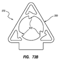
[0154] FIGS. 73A and 73B depict yet another embodiment of a radiopaque identification feature, wherein the
[0155]図75A〜75Cは、図73A及び73Bに示されるものに加え、本実施形態のようにプラスチックポートを含むポートの、所定の属性又は特徴を識別するための識別特徴200としての役割を果たすために含まれる、放射線不透過性インサートの別の実施例の実装を示す。特に、ポート710のキャップ714とベース716との間に挿入されるように構成された、放射線不透過性インサート670が示される。本明細書に示されるインサート670は、ポート710の二重流体腔712を覆って適合するように構成されるが、様々な放射線不透過性組成物を含む他のインサートが、他の方法でポートに含まれるように構成され得る。さらに、ポートは、限定なしに、セプタム718に覆われた1つ、2つ、又はそれよりも多い流体腔を画定し得る。
[0155] FIGS. 75A-75C, in addition to those shown in FIGS. 73A and 73B, serve as identification features 200 for identifying predetermined attributes or features of ports including plastic ports as in this embodiment. Fig. 6 shows another example implementation of a radiopaque insert included to fulfill. In particular, a
[0156]図75Bに示されるように、インサート670は、ポートベース716の一部分上に載るように、ポート710の流体腔712を覆って適合する。そのように配置され、インサート670は、ベース及びキャップがポート710を形成するために一緒に噛合する際にベース716とキャップ714との間に挟まれ固定される。かかる噛合は、超音波溶接、接着剤等によって達成され得る。結果として生じるベース716とキャップ714との間のインサート670の挿入は、図75Cに示される。ポート710が患者への埋め込みの後にX線によって後に画像化されると、インサート670は、容易に可視的であり、したがって、ポートの所定の属性/特徴(複数可)を識別できる。
[0156] As shown in FIG. 75B, the
[0157]次に、アクセスポート又は、識別特徴を含む他の埋め込み可能な医療装置の、少なくとも1つの属性又は特徴の、患者の体内への装置の埋め込み後の識別を容易にするために、例えばX線及び蛍光法等の、画像技術との相互作用によって観測可能な識別特徴200の追加の実施形態を説明することにおいて、図76〜77を参照する。記載される実施形態は、単独又は本明細書に記載される他の識別特徴と一緒に含まれ得、様々な寸法、形状、及び他の構成における多様性を有するアクセスポートと共に用いられ得るということが理解される。したがって、本明細書に記載される実施形態は、単に本開示の原理の実施例に過ぎない。 [0157] Next, to facilitate identification of at least one attribute or feature of an access port or other implantable medical device that includes an identification feature after implantation of the device into the patient's body, for example In describing additional embodiments of the discriminating features 200 that can be observed by interaction with imaging techniques, such as X-ray and fluorescence techniques, reference is made to FIGS. The described embodiments can be included alone or in conjunction with other identifying features described herein and can be used with access ports having a variety of sizes, shapes, and variations in other configurations. Is understood. Accordingly, the embodiments described herein are merely examples of the principles of the present disclosure.
[0158]特に、図76は、放射線不透過性識別特徴200を含む放射線不透過性インサート750を示す。インサート750は、概して三角形の形状を画定し、中央円形穴752A、及び三角形の形状のインサートの頂点の付近に配置される3つの三角形穴752Bを包含する。3つの内向きに伸長するこぶ752Bは、中央円形穴752Aの周辺の周囲に含まれる。
[0158] In particular, FIG. 76 shows a
[0159]英数字表示部200Aはまた、インサート750の下部部分上に含まれるが、かかる表示部は、位置的配置、寸法、種類等において変化し得るということが理解される。本実施形態における識別特徴200の表示部200Aは、字「C」及び「T」を含み、図77に示されるアクセスポート510等の、インサートが含まれるアクセスポートの属性を示す。
[0159] An
[0160]詳細には、図77は、アクセスポート510のベース部516の底表面752上に配置されたインサート750を示すが、インサート及びアクセスポートの他の位置的関係が可能である。インサート750は、図77に示される表示のように、インサート750をアクセスポート510の底から見たときに英数字表示部200Aが反転構成となるように、配置される。このように、英数字表示部200Aは、ポートを上からX線技術によって画像化するときの順方向構成におけるアクセスポート510を通して可視的である。
[0160] In particular, FIG. 77 shows the
[0161]既に示されたように、本実施形態における識別特徴200の表示部200Aは、インサート750によって画定された「C」及び「T」字形状の穴を含み、アクセスポート510の所定の属性を示す。本実施形態では、識別特徴200及び英数字表示部200Aは、アクセスポート510が高圧注入可能であるということを示す。当然のことながら、所望であれば、アクセスポートの他の属性が識別特徴によって指定され得る。
[0161] As already indicated, the
[0162]インサート750は、アクセスポート510又は十分に放射線不透過性でない他の好適な医療装置がX線下で画像化される際に、識別特徴200を提供するために、放射線不透過性となるように構成される。好適に画像化される、十分に放射線不透過性でないアクセスポートの例は、例えばアセチル樹脂等の熱可塑性樹脂を含むものを含む。そのように画像化され、アクセスポート510のインサート750は、放射線画像において可視的であり、したがって、識別特徴200に関する所定のポート属性のX線画像を見る臨床医に、所望の識別を提供する。特に、インサート750自体の放射線不透過性は、放射線透過性の「C」及び「T」英数字表示部200A並びにインサートによって画定された他の特徴に対するコントラストを提供し、よってこれらの特徴をX線画像において容易に特定できるようにする。
[0162] The
[0163]識別特徴及び表示部に用いられた特定の項目は、本明細書に記載されるものから変化し得るということが理解される。実際に、様々な文字、記号、模様、語等が用いられ得る。任意追加的に、所望のように、識別特徴は、ネガティブ又はポジティブレリーフにおいて画定され得る。さらに、インサート750の識別特徴200との関連で上述した幾何学的穴及び表示部は、一緒に又は別個に、アクセスポート510又は当業者に理解され得るようなインサートを含む他の埋め込み可能装置の、1つ以上の属性を画定し得るということが理解される。当然のことながら、インサート自体の形状もまたここで示されるものから変化し得る。
[0163] It will be understood that the specific items used in the identification features and display may vary from those described herein. In fact, various characters, symbols, patterns, words, etc. can be used. Optionally, as desired, the identification feature can be defined in a negative or positive relief. Further, the geometric holes and indicators described above in connection with the identifying
[0164]本実施形態では、インサート750は、アセチル樹脂及び三酸化ビスマスを含む混合物を含む。一実施形態では、例えば、インサート750は、約70重量%のアセチルレジン、例えば銘柄DELRIN(登録商標)の下で販売されるポリオキシメチレン(「POM」)、及び約30重量%の三酸化ビスマスを含む混合物を含む。インサート及び他の要素の、所望の放射線不透過性に依存し、これらの2つの材料の他の相対的に異なる濃度もまた使用され得る。例えば、10、20、50%等を含む、相対的により低い又はより高い濃度の三酸化ビスマスが用いられ得る。同様に、本実施形態では、インサートの厚さは、約0.051センチメートル(0.020インチ)であるが、他のインサートの厚さが使用され得た。さらに、言及したように、インサートの形状、寸法、及び設計は、添付の図表に示されるものから変化し得る。一実施形態では、三酸化ビスマスは、成型の前に混合物を画定するために、粉末形態のアセチル樹脂に添加されるが、三酸化ビスマスの他の形態又は他の好適な放射線不透過性材料もまた用いられ得る。
[0164] In this embodiment, the
[0165]インサート750は、一実施形態では、射出成形によって形成されるが、他の実施形態では、機械加工及び他の形成手順を含む他のプロセスが使用され得る。例えば、一実施形態では、インサートは、まず押出材料の長さを押出し、その後押出部を個々のインサートに切断することによって形成される。別の実施形態では、インサートは、造すること又はインサートをベース及び放射線不透過性材料を含む形成シートから切断することによって、提供される。したがって、これら及び他の手順が企図される。
[0165] The
[0166]形成されると、インサート750は、アクセスポートの製造の間アクセスポート510に含まれ得る。一実施形態では、インサート750のアクセスポート510内への組み込みは、インサート成形プロセスによって達成され、このすでに形成されたインサートがアクセスポート成形型に配置され、アクセスポート又はその一部が、最終的に図77に示されるものに外見が類似するポートを製造するために、アクセスポート510の底表面752と実質的に同一表面上に配置される成形型を伴い、成形型の周囲に射出成形される。一実施形態では、アクセスポートのトップ又はキャップ部及びベース部は、別個の成形プロセスによって形成されるということに注目されたい。この場合、インサートは、その成形の間、ベース部へとインサート成形される。その後、アクセスポートのキャップ及びベース部は、例えば超音波溶接等の好適なプロセスを介して、一緒に接合される。一実施形態では、キャップ及びベース部の超音波溶接の間に転送されたエネルギーは、インサートとアクセスポートのベース部との間のインサート成形結合を凝固させることを補助する。
[0166] Once formed, the
[0167]他の実施形態では、インサートをアクセスポートに噛合させるために、例えば、インサートのアクセスポートの所定の陥凹部内への配置を含む、他のプロセスが使用され得るということに注目されたい。後者の場合、インサートは陥凹部内の定位置へと、又は何らかの他の好適な取り付けプロセスによって、超音波溶接され得る。 [0167] Note that in other embodiments, other processes may be used to engage the insert with the access port, including, for example, placement of the insert into the predetermined recess of the access port. . In the latter case, the insert may be ultrasonically welded into place within the recess or by some other suitable attachment process.
[0168]本明細書に示されるアクセスポート510は、キャップ514及びベース516の両方を含むが、他の実施形態では、単一部品又は他の種類の複数部品ポートが、本明細書に記載される原理から利益を得ることができるということに注目されたい。
[0168] Although the
[0169]ポート外部から可視的となるように図77に示されるように配置されたインサート750で、臨床医は、インサートの識別特徴200を見ることができ、埋め込み前にポートの所定の属性を確認できる。言及したように、埋め込み後に、インサート750は、アクセスポート510の放射線画像における識別特徴200の観測によって、ポート属性の識別を可能にする。
[0169] With an
[0170]三酸化ビスマスは金属ではなく、金属酸化物であるため、部分的に三酸化ビスマスから形成されたインサートを含む非金属性アクセスポートは、磁気共鳴映像法(M.R.I)等の、金属の存在が問題となる状況において、困難なく使用され得る。さらに、本実施形態では、インサートのベース材料(アセチル樹脂)は、アクセスポート本体が製造される材料(これもアセチル樹脂)に実質的に類似する。したがって、両者は、膨張及び収縮について類似する係数を含む。これは、インサート及び取り囲むポート本体材料が、インサート成形プロセスが完了した後に冷却する際に、インサートの歪みを防止する。さらに、インサートは、相対的に柔らかいベース材料を含むため、インサートがインサート成形プロセスの間に何らかの形で誤って配置された場合、成形型は損傷されない。 [0170] Since bismuth trioxide is not a metal but a metal oxide, non-metallic access ports that include inserts partially formed from bismuth trioxide are suitable for magnetic resonance imaging (MR), etc. In situations where the presence of metal is a problem, it can be used without difficulty. Furthermore, in this embodiment, the base material of the insert (acetyl resin) is substantially similar to the material from which the access port body is manufactured (also acetyl resin). Thus, both contain similar coefficients for expansion and contraction. This prevents distortion of the insert when the insert and surrounding port body material cools after the insert molding process is complete. Further, since the insert includes a relatively soft base material, the mold will not be damaged if the insert is misplaced in any way during the insert molding process.
[0171]言及したように、放射線不透過性インサート750及び本明細書に記載される他のインサートの製造において、アセチル樹脂の代わりに好適な生体適合性のベース材料、及び三酸化ビスマスの代わりに好適な生体適合性の放射線不透過性材料を含む、他の材料が用いられ得る。インサートを形成するための1つの好適な組み合わせは、MAKROLON(登録商標)2558の名の下で販売されるポリカーボネートのベース材料及び放射線不透過性材料としてタングステンを含む。他の好適なベース材料は、生体適合性の熱可塑性樹脂材料を含む。他の可能な放射線不透過性材料は、金、銀等を含む貴金属、硫酸バリウム及び他の好適な硫酸塩、好適な酸化物、並びにアルミナ、ジルコニア等を含む好適な密度のセラミックを含む。したがってかかる材料が企図される。
[0171] As mentioned, in the manufacture of
[0172]一実施形態では、アクセスポート本体の形成に用いられた材料と同じベース材料の使用は、インサートが成形プロセスの間ポート本体のものと同じ速度で収縮することを可能にし、よって望ましくはポート本体又はインサートの歪みを防止する。 [0172] In one embodiment, the use of the same base material as the material used to form the access port body allows the insert to shrink at the same rate as that of the port body during the molding process, and thus desirably Prevent distortion of the port body or insert.
[0173]言及したように、識別特徴を含むインサートは、他の構成を含み得、その一実施例が図78に示され、ここでインサート800は、例えば図66D及び67に示されるものに類似するもの等の、2つのリザーバアクセスポートにおける使用のために示される。これまでのように、インサート800は、英数字表示部200Aを同様に含む識別特徴200を含む。インサート800の形状は、それぞれの三角形が、「C」及び「T」字形状の穴の2つの英数字表示部200Aのうちの1つ、並びに三角形の頂点のいくつかに配置された三角形穴を伴う、接続した三角形の設計を含む。
[0173] As mentioned, an insert that includes an identifying feature may include other configurations, one example of which is shown in FIG. 78, where the
[0174]同様にこれまでのように、アクセスポート又は他の埋め込み可能装置に含まれ、X線画像技術を使用して放射線画像化された際に、インサートを放射線不透過性にするために、インサート800の組成物は、アセチル樹脂及び三酸化ビスマスの、前の実施形態のものに類似する相対的濃度での混合物を含む。再び、多数の異なる文字、模様、及び/又は組み合わせ構成が、可能である。例えば、アクセスポートを高圧注入可能として識別することに加え、この及び本明細書に記載される他の識別特徴は、ロット番号、病院識別、ポート銘柄等を指定するために使用され得る。
[0174] As before, to make the insert radiopaque when included in an access port or other implantable device and radiographed using X-ray imaging technology, The composition of the
[0175]図80及び81は、識別特徴を含むインサートのための、さらに別の可能な構成を描写し、ここではコンポーネント850が示される。コンポーネント850は、コンポーネント850が含まれるポート又は医療装置の一態様の放射線画像確認を提供する、英数字表示部200Aを同様に含む、識別特徴200を含む。特に、コンポーネント850の識別特徴200は、概して三角形の形状のコンポーネントの頂点に配置された、「C」及び「T」字形状の穴の、3つの英数字表示部200Aを含む。本実施形態では、コンポーネント850は、コンポーネントがアクセスポートの外周の周囲に適合することを可能にするための穴を画定するが、他の形状及び構成が可能であるということが理解される。これまでのように、アクセスポート又は、他の埋め込み可能装置に含まれ、X線画像技術を使用して放射線画像化された際に、コンポーネントを放射線不透過性にするため、本実施形態におけるコンポーネント850の組成物は、アセチル樹脂及び三酸化ビスマスの、前の実施形態のものに類似する相対的濃度での混合物を含む。
[0175] FIGS. 80 and 81 depict yet another possible configuration for an insert that includes an identification feature, where a
[0176]図79A〜79Cは、アクセスポートベース516又はアクセスポートの他の好適な部内でのインサート750の配置のための1つの可能な実施形態を描写し、ここで陥凹部810は、ポートベースの第1の成形部内に画定される。図79Bに見られるように、放射線不透過性インサート750は、上記の好適なプロセスによるその形成の後、陥凹部810内に配置され、追加のベース部812が、溶接、外側被覆、又は他の好適なプロセスによって陥凹部を覆って形成される。インサート750は、したがってポートベース516内に封入される。この様式でのインサートの封入は、放射線不透過性インサートにおける生体適合性の材料の使用の必要性を排除し得る。アクセスポート内の陥凹部及びインサートの両方の、寸法及び配置は、本明細書に示されるものから変化し得るということに注目されたい。例えば、陥凹部は、インサートをそこに滑らせることができるように寸法決定されるポート本体の一部分上の溝を含み得、その後溝はインサートを覆うために蓋を被せられる。
[0176] FIGS. 79A-79C depict one possible embodiment for placement of the
[0177]本明細書に記載される原理に従う放射線不透過性識別特徴は、他の適用において使用され得るということが理解される。例えば、一実施形態では、好適なベース材料及び三酸化ビスマス、又は本明細書に記載される他の好適な放射線不透過性材料を含む、放射線不透過性識別特徴は、カテーテルのルーメンの遠位端プラグとして用いられ得る。したがって、これら及び他の可能な適用が企図される。 [0177] It will be appreciated that radiopaque identification features in accordance with the principles described herein may be used in other applications. For example, in one embodiment, the radiopaque identification feature, including a suitable base material and bismuth trioxide, or other suitable radiopaque material described herein, is distal to the lumen of the catheter. It can be used as an end plug. Thus, these and other possible applications are contemplated.
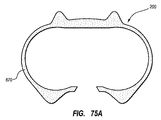
[0178]次に、一実施形態に従い、概して910に指定される、埋め込み可能アクセスポート(「ポート」)に関する様々な詳細を記載することにおいて、図82、83A、及び83Bを参照する。示されるように、ポート910は、本体を形成するために一緒に噛合可能な、ベース部916及びキャップ部914をさらに含む、本体913を含む。図82に見られるように、一緒に噛合されると、ベース及びキャップ部916、914は、流体腔912を画定するために協働し、これは図83Aにおいてより明確に見られる。キャップ部914は、流体腔912への針のアクセスを提供するために、針穿刺可能セプタム918が挿入された開口部920を画定する。セプタム918は、任意追加的に、ポートの埋め込み後にセプタムが臨床医によって触診され皮膚下で位置付けられることを可能にする、1つ以上の触診特徴922を含む。ポート本体及びセプタムの特定の寸法、形状、及び構成は、本明細書に示され記載されるものから変化し得るということに注目されたい。
[0178] Reference is now made to FIGS. 82, 83A, and 83B in describing various details regarding implantable access ports (“ports”), generally designated 910, according to one embodiment. As shown, the
[0179]流体腔912との流体連通における導管を提供するステム931は、ポート本体913のベース部916と一体式で形成される。さらに、それぞれのプラグがポート本体913内に画定される対応する縫合穴928内に配置される、複数の縫合プラグ926が含まれる。
[0179] A
[0180]本実施形態では、ポート本体913は、ポリエーテルエーテルケトン(「PEEK」)を含む。PEEKは、ポート910が、ポートを通る粘着性造影剤流体の高圧注入に関連する圧力に断裂なく耐えられるようにする、相対的に強い熱可塑性樹脂である。高圧注入流速は、典型的に1秒当たり約5mlである。PEEKの相対的な強度は、図83A及び83Bにおいて最もよく見られるように、ステム931のベース部916との一体式形成もまた容易にし、よってポート本体の構造を簡素化する。実際に、相対的に強いPEEK材料は、使用の間の断裂を回避するための十分なステム強度を維持しながら、そこを通る流体の高圧注入を可能にする十分に大きい内径を画定するために、ステム931が一体式で形成されることを可能にする。さらに、PEEK等の相対的に強い材料からのベース部916の形成は、ポート910内に挿入される針による穿刺への抵抗に依然として成功しながら、流体腔912を画定するベースの底床を相対的に薄くすることを可能にする。他の好適で相対的に強度の高いプラスチックもまた、他の実施形態で用いられ得るということに注目されたい。ベース部916及びキャップ部914は、例えば射出成形を含む好適なプロセスによって形成される。
[0180] In the present embodiment, the
[0181]図83A、83B、85A、及び85Bは、ポート本体913のベース部916が、ベースの底部から伸長する複数の足932を含むということを示す。ベース部916は、その上表面上に、後に見られるように、ベース部をポート本体913のキャップ部914と永久的に噛合させることにおいて用いられる、リップ934をさらに画定する。キャップ部914は、後に見られるように、開口部920の周囲に円周的に配置され、キャップ部をベース部916に噛合させることにおいて用いられる、複数の溶接特徴936(図83B)を含む。本実施形態では、溶接特徴936は、複数の三角形の歯として配置されるが、他の実施形態では、他の好適な溶接特徴が用いられ得る。本実施形態での複数の離散的溶接特徴936の使用は、環状リッジ等の単一の溶接特徴構成と比較した際に、超音波溶接手順の相対的により速い完了を提供する。
[0181] FIGS. 83A, 83B, 85A, and 85B show that the
[0182]上でさらに考察した前の実施形態におけるように、図83A及び83Bは、患者の体内への装置の埋め込み後に、識別特徴を含むアクセスポート又は他の埋め込み可能な医療装置の少なくとも1つの属性又は特徴の識別を容易にするために、本実施形態のポート910が、例えばX線及び蛍光法等の画像技術との相互作用によって観測可能な、放射線不透過性識別特徴200を含むということを示す。再び、記載される実施形態は、単独又は本明細書に記載される他の識別特徴と一緒に含まれ得、様々な寸法、形状、及び他の構成における多様性を有するアクセスポートと共に用いられ得るということが理解される。したがって、本明細書に記載される実施形態は、単に本開示の原理の実施例に過ぎない。
[0182] As in the previous embodiment discussed further above, FIGS. 83A and 83B illustrate at least one of an access port or other implantable medical device that includes an identification feature after implantation of the device in a patient's body. To facilitate identification of attributes or features, the
[0183]本実施形態における識別特徴200は、放射線不透過性インサート940として実装される。インサート940は、十分に放射線不透過性の材料及びベース材料を含む。本実施形態では、DELRIN(登録商標)の名称の下で一般的に販売されるもの等のアセチル樹脂のベース材料と混合され、三酸化ビスマスが放射線不透過性材料として用いられる。本実施形態では、放射線不透過性インサート940のための材料組成物は、約30重量%の三酸化ビスマス及び約70重量%のアセチル樹脂を含むが、これらのパーセンテージは、必要性又は他の要因に従って変化し得る。インサート940は、溶接、押出し、機械加工等の、様々なプロセスで製造され得る。一実施形態では、インサート940は、約0.084センチメートル(0.033インチ)の最小限の厚さ、約2.0センチメートルの長さ、及び約1.5センチメートルの幅(0.8インチ及び幅約0.6インチ)を有するように製造され、それらこれらの外形寸法は、適用に従って変化し得る。
[0183] The
[0184]他の非金属性放射線不透過性材料が、三酸化ビスマスの代わりに放射線不透過性インサートにおいて用いられ得るということが理解される。かかる材料は、非制限的な例として、次炭酸ビスマス又はオキシ塩化ビスマスを含むビスマス化合物、セラミック粉末、及び酸化ジルコニウム、酸化アルミニウム、二酸化チタン等を含む化合物を含む。三酸化ビスマス、次炭酸ビスマス、オキシ塩化ビスマス、及び他の好適な化合物は、相対的に放射線不透過性の低い材料が放射線不透過性インサートにおいて必要とされることを可能にする典型的放射線乳白剤である硫酸バリウムより、相対的により放射線不透過性であり、よってアセチル樹脂又は放射線不透過性インサートの他のベース材料の特性をより低い程度に変化させる。一実施形態では、インサートは、約25〜約40重量%のオキシ塩化ビスマス又は次炭酸ビスマスを、残部にアセチル樹脂を伴って含み得るが、多数の他の組成物比率が可能であり本明細書で企図される。別の実施形態では、インサートは、約45〜約50重量%の酸化ジルコニウムを、残部にアセチル樹脂を伴って含み得るが、多数の他の組成物比率が可能であり本明細書で企図される。また、他のベース材料がアセチル樹脂の代わりに放射線不透過性インサートにおいて用いられ得るということに注目されたい。 [0184] It is understood that other non-metallic radiopaque materials can be used in radiopaque inserts instead of bismuth trioxide. Such materials include, as non-limiting examples, bismuth compounds including bismuth carbonate or bismuth oxychloride, ceramic powders, and compounds including zirconium oxide, aluminum oxide, titanium dioxide, and the like. Bismuth trioxide, bismuth tricarbonate, bismuth oxychloride, and other suitable compounds are typical radiation milks that allow relatively less radiopaque materials to be required in radiopaque inserts. It is relatively more radiopaque than the agent barium sulfate, thus changing the properties of the acetyl resin or other base material of the radiopaque insert to a lesser extent. In one embodiment, the insert may comprise about 25 to about 40% by weight bismuth oxychloride or bismuth subcarbonate with the balance being acetyl resin, although numerous other composition ratios are possible and are described herein. Is contemplated. In another embodiment, the insert may include about 45 to about 50 weight percent zirconium oxide, with the balance being acetyl resin, although numerous other composition ratios are possible and contemplated herein. . It should also be noted that other base materials can be used in radiopaque inserts instead of acetyl resins.
[0185]図84に示されるように、放射線不透過性インサート940は、既に言及したように、成形、機械加工、押出し、又は他の好適な製作様式によって形成された本体を含む。本実施形態における放射線不透過性インサート940の本体は、おおむね三角形構成を画定し、矢じり形状との類似性を持つ。中央穴942は、インサートがポート本体913のベース部916を覆って適合できるように、放射線不透過性インサート940の本体によって画定される(図85A、85B)。足輪郭944及びステム輪郭946もまた、下記のように、ポート本体の部分間の放射線不透過性インサートの挟持を容易にするために、放射線不透過性インサート940の本体によって画定される。側部構成から見ると(図83B)、足及びステム輪郭944及び946は、放射線不透過性インサート940の本体内の隆起したセグメントを画定する。当然のことながら、これらの隆起した特徴は、ポート本体の特定の構成に整合するために構成において変化し得る。
[0185] As shown in FIG. 84, the
[0186]放射線不透過性インサート940は、ポート910の所定の特徴又は属性を識別することを補助する、1つ以上の放射線画像で認識可能な識別特徴又は表示部を、さらに含む。本実施形態では、放射線不透過性インサート940は、上でさらに考察した実施形態のように、ここでは字「C」及び「T」として実装される、英数字表示部200Aを含み、これは、概してポート10が1秒当たり約5mlの流速で高圧注入可能であるということを示す、と認識される。臨床医にポートの所定の特徴を伝達するために、様々な記号、数字、文字、又は他の表示部が放射線インサート上に含まれ得るということに注目されたい。本実施形態では、所定の特徴は、ポートの高圧注入可能性についてのものであるが、他の実施形態では、放射線不透過性インサートの表示部によって他の特徴、属性、及び/又は特性が伝達され得るということに注目されたい。
[0186] The
[0187]図85A及び85Bは、放射線不透過性インサート940のポート本体913のポートベース916との係合の様式を示す。示されるように、放射線不透過性インサートの中央穴942がベース部の円柱状本体を収容するように、放射線不透過性インサート940は、ベース部916に係合する。図85Bに示すように、放射線不透過性インサート940は、ベース部916上に据えられ、そのため足輪郭944のそれぞれがベース部の対応する足932の上に載り、ステム輪郭946がステム931の上に載る。
[0187] FIGS. 85A and 85B illustrate the manner of engagement of the
[0188]同様に、図86及び87は、放射線不透過性インサート940のポート本体913のキャップ部914との様式係合を示す。詳細には、図86は、キャップ部914が、放射線不透過性インサートのステム輪郭946を収容するために寸法決定されたステム陥凹部950Aを含む、放射線不透過性インサート940を収容するために形作られた陥凹部950を画定するということを示す。したがって、一実施形態では、放射線不透過性インサート940がキャップ部914とベース部916との間に挟持されると、足輪郭944及びステム輪郭946は、キャップ部及びベース部並びに又はポートの他の部品の、対応して形作られた特徴の間に挿入される。
[0188] Similarly, FIGS. 86 and 87 show the modal engagement of the
[0189]上述の放射線不透過性インサート940のキャップ914及びベース916との係合は、インサートがポート910の製造の間挟持構成でキャップとベースとの間に挿入されることを可能にする。具体的には、ポート製造の間、放射線不透過性インサート940は、ポート本体ベース部916とキャップ914との間に、図85B又は87に示されるものに類似する様式で挿入される。放射線不透過性インサートを定位置に維持するために、重力がそれを定位置に維持するような配置、一時的固着等、任意の好適な方法が用いられ得る。
[0189] The engagement of the
[0190]キャップ部914の開口部920内の位置におけるセプタム918(図83B)を伴い、ベース部916及びキャップ部は、その間に挿入された放射線不透過性インサート940を伴って、一緒に噛合される。超音波溶接は、キャップ部914の溶接特徴936をベース部916のリップ934に結合させるために行われる。これは密閉可能的にベース及びキャップ部916、914を一緒に噛合し、これにより流体腔912を密閉し、図88に示されるように、放射線不透過性インサート940を2つの本体部間の挟持構成において固定する。特に、ステム931及びベース916の足932がインサート940を定位置に固定するということに注目されたい。本実施形態では、ベース916の足932は、縫合プラグ926のそれぞれをそれぞれの縫合穴928内の定位置に固定するということにもまた注目されたい。したがって、放射線不透過性インサートは、機械的様式によって定位置に永久的には締結されず、むしろ溶接が完了した後で固定されるということが注目される。
[0190] With the septum 918 (FIG. 83B) at a position within the
[0191]図88に示されるように、本実施形態では、埋め込み前のポートの視覚的検査及び識別を可能にするために、ID特徴200及びその英数字表示部200Aを含む、放射線不透過性インサート940の一部が、ポート910の外側に残り、その底から可視的に留まる。対応して、インサート940の放射線不透過性は、X線画像技術による埋め込み後のポート910の識別を可能にする。
[0191] As shown in FIG. 88, this embodiment includes a radiopaque, including
[0192]一実施形態では、結果として生じるアクセスポートの噛合又は一体性に影響することなく、ベース及びキャップ部は、ポートに含まれる放射線不透過性インサートを伴わずに一緒に溶接され得るということが注目される。本明細書に記載される原理は、例えば二重リザーバアクセスポート等の、様々な医療装置及びアクセスポートに拡張され得るということにもまた注目されたい。 [0192] In one embodiment, the base and cap portion can be welded together without the radiopaque insert included in the port without affecting the resulting access port engagement or integrity. Is noticed. It should also be noted that the principles described herein can be extended to a variety of medical devices and access ports, such as dual reservoir access ports.
[0193]アセチル樹脂及び三酸化ビスマスを含む放射線不透過性インサートの組み込みは、合わせてPEEKからのポート本体の形成を伴い、X線画像技術を介してなお識別可能な、非金属性ポートを製造するということに注目されたい。これは、患者が、患者の体内の皮下定位置のポートを伴って、MRI、CT、又はX線走査を受ける際に、ポートが望ましくない画像アーチファクトを製造するリスクを低減又は排除する。これは、より明確なMRI走査を可能にし、より正確な診断をもたらす。さらに、及び言及したように、一実施形態では、本アクセスポートは、そこを通る造影剤又は他の粘着性流体の高圧注入に耐えるように構成される。かかる高圧注入は、より正確的に患者の状態を診断するために、しばしばCT走査、MRI走査等に関連して行われる。 [0193] The incorporation of a radiopaque insert containing acetyl resin and bismuth trioxide together with the formation of a port body from PEEK produces a non-metallic port that is still identifiable via X-ray imaging technology. Note that you do. This reduces or eliminates the risk that the port will produce unwanted image artifacts when the patient undergoes an MRI, CT, or X-ray scan with a subcutaneously located port in the patient's body. This allows for a clearer MRI scan and results in a more accurate diagnosis. Further and as mentioned, in one embodiment, the access port is configured to withstand high pressure injection of contrast agent or other adhesive fluid therethrough. Such high pressure injections are often performed in conjunction with CT scans, MRI scans, etc. to more accurately diagnose patient conditions.
[0194]特定の代表的実施形態及び詳細が、本開示によって企図される態様を例証する目的のために示されてきた一方で、当業者には、本明細書で開示される方法及び器具における様々な変化が、添付の請求項によって画定される、本開示によって企図される範囲から逸脱することなく、起こり得るということが明らかとなるであろう。例えば、他のアクセスポート寸法及び形状が用いられ得、本開示によって企図されるアクセスポートの少なくとも1つの識別可能な特徴を形成するために、様々な他の実施形態及び構造が用いられ得る。特に、アクセスポートは、任意の数の形状及び寸法で形成され得、そのため、本開示の趣旨及び範囲から逸脱することなく、本明細書に記載及び例証される任意の実施形態に対する任意の数の変更及び変化が可能である。 [0194] While certain representative embodiments and details have been presented for purposes of illustrating aspects contemplated by the present disclosure, those skilled in the art will perceive in the methods and devices disclosed herein. It will be apparent that various changes can be made without departing from the scope contemplated by the present disclosure as defined by the appended claims. For example, other access port dimensions and shapes can be used, and various other embodiments and structures can be used to form at least one identifiable feature of an access port contemplated by the present disclosure. In particular, the access port may be formed in any number of shapes and dimensions, and thus any number of any of the embodiments described and illustrated herein without departing from the spirit and scope of the present disclosure. Changes and changes are possible.
Claims (20)
互いと協働的に噛合されたベース部及びキャップ部を含むポート本体と、
前記ベース部及び前記キャップ部のうちの少なくとも一方によって画定された流体腔と、
前記ベース部及びキャップ部のうちの一方と一体式で形成され、前記流体腔と流体連通するステムと、
前記流体腔の開口部を覆う針穿通可能セプタムと、
放射線不透過性インサートであって、
放射線不透過性材料を含み、前記ベース部及び前記キャップ部が噛合されるときに、前記ベース部と前記キャップ部との間に固定して挿入されるように形作られた、本体であって、さらに前記放射線不透過性インサートが前記ベース部及び前記キャップ部のうちの少なくとも一方の外形の周囲に適合することを可能にする、少なくとも1つの輪郭部を画定する、本体と、
患者内の前記アクセスポートの皮下埋め込み後にX線画像技術を介して観察可能であり、観測者に前記アクセスポートの所定の属性を伝達する、少なくとも1つのしるしと、を含むインサートと、を含む
前記放射線不透過性インサートが、前記ステムと、該ステムを受け入れるように前記キャップ部によって画定される凹部と、の間に適合する輪郭部を含む、アクセスポート。 An embeddable access port,
A port body including a base portion and a cap portion cooperatively engaged with each other;
A fluid cavity defined by at least one of the base portion and the cap portion;
A stem formed integrally with one of the base portion and the cap portion, and in fluid communication with the fluid cavity;
A needle pierceable septum covering the opening of the fluid cavity;
A radiopaque insert,
A body, comprising a radiopaque material, shaped to be fixedly inserted between the base and the cap when the base and the cap are engaged, A body defining at least one contour that allows the radiopaque insert to fit around a contour of at least one of the base portion and the cap portion;
An insert that includes at least one indicia that is observable via X-ray imaging techniques after subcutaneous implantation of the access port in a patient and communicates a predetermined attribute of the access port to an observer. radiopaque insert comprises said stem, and a concave portion that will be defined by the cap portion to receive said stem, an adapted contour between, the access port.
ポート本体、セプタム及びステムを提供することを含み、
前記ポート本体が、ベース部と、キャップ部と、を含み、
前記ステムが、前記ベース部及び前記キャップ部のうちの一方と一体的に形成され、前記ベース部及び前記キャップ部のうちの少なくとも一方によって画定された流体腔と流体連通し、
前記方法は、さらに、
患者内の前記アクセスポートの皮下埋め込み後にX線画像技術を介して観測可能であり、観測者に前記アクセスポートが高圧注入可能であるということを伝達する少なくとも1つのしるしと、前記ステムと、該ステムを受け入れるように前記キャップ部によって画定される凹部と、の間に適合する輪郭部と、を含む、放射線不透過性インサートを提供することと、
前記放射線不透過性インサートの輪郭部が、前記ベース部の外形と前記キャップ部の外形との間に適合するように、前記放射線不透過性インサートを前記ベース部と前記キャップ部との間に挿入することと、
前記放射線不透過性インサートの一部分が前記ポート本体の外側に留まるように、前記ベース部を前記キャップ部に、放射線不透過性インサートがその間に挿入された状態で、協働的に噛合させることと、を含む方法。 An access port manufacturing method comprising:
Providing a port body, septum and stem;
The port body includes a base portion and a cap portion;
The stem is integrally formed with one of the base portion and the cap portion and is in fluid communication with a fluid cavity defined by at least one of the base portion and the cap portion;
The method further comprises:
At least one indicia observable via X-ray imaging techniques after subcutaneous implantation of the access port in a patient and communicating to the observer that the access port is capable of high pressure infusion; the stem ; includes a concave portion that will be defined by the cap portion to receive the stem, and a contour fit between, providing a radiopaque insert,
Inserting the radiopaque insert between the base portion and the cap portion such that a contour portion of the radiopaque insert fits between the outer shape of the base portion and the outer shape of the cap portion. To do
Cooperatingly engaging the base portion with the cap portion with the radiopaque insert inserted therebetween so that a portion of the radiopaque insert remains outside the port body. , Including methods.
互いに協働的に噛合され、ポリエーテルエーテルケトンを含む、ベース部及びキャップ部を含む、ポート本体と、
前記ベース部及び前記キャップ部によって画定された流体腔と、
前記ベース部と一体式で形成され、前記流体腔と流体連通する、ステムと、
前記キャップ部によって画定される前記流体腔の開口部を覆う、針穿通可能セプタムと、
放射線不透過性インサートであって、
ビスマス含有材料を含み、前記ベース部及び前記キャップ部が噛合されるときに、前記ベース部と前記キャップ部との間に固定して挿入されるように形作られ、さらに前記放射線不透過性インサートが前記ベース部の前記ステムの周囲に適合することを可能にする少なくとも1つの輪郭部を画定する、本体と、
患者内の前記アクセスポートの皮下埋め込み後にX線画像技術を介して観測可能であり、観測者に前記アクセスポートが高圧注入可能であるということを伝達する、少なくとも1つのしるしとを含む、インサートと、を含み、
前記放射線不透過性インサートが、前記ステムと、該ステムを受け入れるように前記キャップ部によって画定される凹部と、の間に適合する輪郭部を含む、アクセスポート。 An embeddable access port,
A port body cooperatingly engaged with each other and comprising a polyether ether ketone, including a base portion and a cap portion;
A fluid cavity defined by the base portion and the cap portion;
A stem formed integrally with the base portion and in fluid communication with the fluid cavity;
A needle-penetrable septum that covers the opening of the fluid cavity defined by the cap portion;
A radiopaque insert,
A bismuth-containing material, wherein the base portion and the cap portion are configured to be fixedly inserted between the base portion and the cap portion when the base portion and the cap portion are engaged, and the radiopaque insert further comprises A body defining at least one contour that allows the base portion to fit around the stem;
An insert comprising at least one indicia that is observable via X-ray imaging techniques after subcutaneous implantation of the access port in a patient and communicates to the observer that the access port is capable of high pressure infusion; Including,
The radiopaque insert comprises said stem, and a concave portion that will be defined by the cap portion to receive said stem, an adapted contour between, the access port.
Applications Claiming Priority (5)
| Application Number | Priority Date | Filing Date | Title |
|---|---|---|---|
| US201261691725P | 2012-08-21 | 2012-08-21 | |
| US61/691,725 | 2012-08-21 | ||
| US13/776,517 US8939947B2 (en) | 2005-03-04 | 2013-02-25 | Systems and methods for radiographically identifying an access port |
| US13/776,517 | 2013-02-25 | ||
| PCT/US2013/056019 WO2014031763A2 (en) | 2012-08-21 | 2013-08-21 | Implantable access port including a sandwiched radiopaque insert |
Related Child Applications (1)
| Application Number | Title | Priority Date | Filing Date |
|---|---|---|---|
| JP2019005900A Division JP6887453B2 (en) | 2012-08-21 | 2019-01-17 | Embeddable access port with sandwiched radiation opaque insert |
Publications (2)
| Publication Number | Publication Date |
|---|---|
| JP2015526198A JP2015526198A (en) | 2015-09-10 |
| JP6470177B2 true JP6470177B2 (en) | 2019-02-13 |
Family
ID=50150484
Family Applications (3)
| Application Number | Title | Priority Date | Filing Date |
|---|---|---|---|
| JP2015528624A Active JP6470177B2 (en) | 2012-08-21 | 2013-08-21 | Implantable access port with sandwiched radiopaque insert |
| JP2019005900A Active JP6887453B2 (en) | 2012-08-21 | 2019-01-17 | Embeddable access port with sandwiched radiation opaque insert |
| JP2021083568A Active JP7239636B2 (en) | 2012-08-21 | 2021-05-18 | Implantable access port containing clamped radiopaque insert |
Family Applications After (2)
| Application Number | Title | Priority Date | Filing Date |
|---|---|---|---|
| JP2019005900A Active JP6887453B2 (en) | 2012-08-21 | 2019-01-17 | Embeddable access port with sandwiched radiation opaque insert |
| JP2021083568A Active JP7239636B2 (en) | 2012-08-21 | 2021-05-18 | Implantable access port containing clamped radiopaque insert |
Country Status (4)
| Country | Link |
|---|---|
| EP (2) | EP2887995B8 (en) |
| JP (3) | JP6470177B2 (en) |
| ES (1) | ES2745264T3 (en) |
| WO (1) | WO2014031763A2 (en) |
Families Citing this family (24)
| Publication number | Priority date | Publication date | Assignee | Title |
|---|---|---|---|---|
| US8029482B2 (en) | 2005-03-04 | 2011-10-04 | C. R. Bard, Inc. | Systems and methods for radiographically identifying an access port |
| US9474888B2 (en) | 2005-03-04 | 2016-10-25 | C. R. Bard, Inc. | Implantable access port including a sandwiched radiopaque insert |
| US7947022B2 (en) | 2005-03-04 | 2011-05-24 | C. R. Bard, Inc. | Access port identification systems and methods |
| EP1858565B1 (en) | 2005-03-04 | 2021-08-11 | C.R. Bard, Inc. | Access port identification systems and methods |
| US8202259B2 (en) | 2005-03-04 | 2012-06-19 | C. R. Bard, Inc. | Systems and methods for identifying an access port |
| EP1874393B1 (en) | 2005-04-27 | 2017-09-06 | C.R.Bard, Inc. | Infusion apparatuses |
| US10307581B2 (en) | 2005-04-27 | 2019-06-04 | C. R. Bard, Inc. | Reinforced septum for an implantable medical device |
| EP2324878B1 (en) | 2005-04-27 | 2014-08-20 | C.R. Bard, Inc. | Infusion apparatuses provided with septum |
| US9265912B2 (en) | 2006-11-08 | 2016-02-23 | C. R. Bard, Inc. | Indicia informative of characteristics of insertable medical devices |
| US9642986B2 (en) | 2006-11-08 | 2017-05-09 | C. R. Bard, Inc. | Resource information key for an insertable medical device |
| US9579496B2 (en) | 2007-11-07 | 2017-02-28 | C. R. Bard, Inc. | Radiopaque and septum-based indicators for a multi-lumen implantable port |
| US11890443B2 (en) | 2008-11-13 | 2024-02-06 | C. R. Bard, Inc. | Implantable medical devices including septum-based indicators |
| US8932271B2 (en) | 2008-11-13 | 2015-01-13 | C. R. Bard, Inc. | Implantable medical devices including septum-based indicators |
| ES2695907T3 (en) | 2009-11-17 | 2019-01-11 | Bard Inc C R | Overmolded access port that includes anchoring and identification features |
| JP2018099255A (en) * | 2016-12-20 | 2018-06-28 | 住友ベークライト株式会社 | Indwelling medical equipment and manufacturing method of indwelling medical equipment |
| JP6992306B2 (en) * | 2017-07-27 | 2022-01-13 | 住友ベークライト株式会社 | Indwelling medical devices and anchoring members |
| JP7106914B2 (en) * | 2018-03-22 | 2022-07-27 | 住友ベークライト株式会社 | Indwelling type medical device, indwelling type medical device set and labeling part set |
| JP7013985B2 (en) * | 2018-03-22 | 2022-02-01 | 住友ベークライト株式会社 | Indwelling type medical equipment, indwelling type medical equipment set including this, sign part set and cover member used in indwelling type medical equipment |
| US20210268250A1 (en) | 2018-06-20 | 2021-09-02 | C. R. Bard, Inc. | Inflatable Ports, Catheter Assemblies Including Inflatable Ports, And Methods Thereof |
| JP2021531087A (en) | 2018-07-13 | 2021-11-18 | バード・ペリフェラル・バスキュラー・インコーポレーテッド | Portable port, portable port detector, and how |
| JP7167524B2 (en) * | 2018-07-30 | 2022-11-09 | 住友ベークライト株式会社 | Indwelling medical device and indwelling medical device set |
| JP7310621B2 (en) * | 2019-03-14 | 2023-07-19 | 住友ベークライト株式会社 | Indwelling medical device |
| WO2023140862A1 (en) * | 2022-01-21 | 2023-07-27 | Bard Peripheral Vascular, Inc. | Port identification insert and assembly alignment feature |
| WO2023140863A1 (en) * | 2022-01-21 | 2023-07-27 | Bard Peripheral Vascular, Inc. | Port identification insert and methods |
Family Cites Families (15)
| Publication number | Priority date | Publication date | Assignee | Title |
|---|---|---|---|---|
| US4802885A (en) * | 1986-06-17 | 1989-02-07 | Medical Engineering Corporation | Self sealing subcutaneous infusion and withdrawal device |
| US5137529A (en) * | 1990-02-20 | 1992-08-11 | Pudenz-Schulte Medical Research Corporation | Injection port |
| US6287293B1 (en) | 1999-09-28 | 2001-09-11 | C. R. Bard, Inc. | Method and apparatus for locating the injection point of an implanted medical device |
| US8029482B2 (en) * | 2005-03-04 | 2011-10-04 | C. R. Bard, Inc. | Systems and methods for radiographically identifying an access port |
| JP4355722B2 (en) * | 2005-11-17 | 2009-11-04 | セイコーエプソン株式会社 | Fluid transport device |
| US7762999B2 (en) * | 2006-02-01 | 2010-07-27 | Ethicon Endo-Surgery, Inc. | Injection port |
| MX2009014100A (en) * | 2007-06-20 | 2010-09-14 | Medical Components Inc | Venous access port with molded and/or radiopaque indicia. |
| EP3311877A1 (en) * | 2007-07-19 | 2018-04-25 | Medical Components, Inc. | Venous access port assembly with x-ray discernable indicia |
| EP2190517A4 (en) * | 2007-09-07 | 2012-08-15 | Angiodynamics Inc | Implantable access port |
| KR101545765B1 (en) * | 2008-04-17 | 2015-08-20 | 알러간, 인코포레이티드 | Implantable Access Port Device and Attachment System |
| US8075536B2 (en) * | 2008-09-09 | 2011-12-13 | Navilyst Medical, Inc. | Power injectable port identification |
| US9623222B2 (en) * | 2008-10-30 | 2017-04-18 | Warsaw Orthopedic, Inc. | Drug depot with anchor |
| US8092435B2 (en) * | 2009-10-16 | 2012-01-10 | Smiths Medical Asd, Inc. | Portal with septum embedded indicia |
| ES2695907T3 (en) * | 2009-11-17 | 2019-01-11 | Bard Inc C R | Overmolded access port that includes anchoring and identification features |
| US20110288503A1 (en) * | 2010-05-20 | 2011-11-24 | Magalich Christopher N | Medical imaging septum and access port device and method |
-
2013
- 2013-08-21 ES ES13830592T patent/ES2745264T3/en active Active
- 2013-08-21 EP EP13830592.5A patent/EP2887995B8/en active Active
- 2013-08-21 JP JP2015528624A patent/JP6470177B2/en active Active
- 2013-08-21 EP EP19166777.3A patent/EP3524314A1/en active Pending
- 2013-08-21 WO PCT/US2013/056019 patent/WO2014031763A2/en active Application Filing
-
2019
- 2019-01-17 JP JP2019005900A patent/JP6887453B2/en active Active
-
2021
- 2021-05-18 JP JP2021083568A patent/JP7239636B2/en active Active
Also Published As
| Publication number | Publication date |
|---|---|
| EP2887995A4 (en) | 2016-04-20 |
| JP6887453B2 (en) | 2021-06-16 |
| WO2014031763A3 (en) | 2014-04-24 |
| JP2015526198A (en) | 2015-09-10 |
| EP3524314A1 (en) | 2019-08-14 |
| EP2887995B8 (en) | 2019-08-21 |
| JP2019088827A (en) | 2019-06-13 |
| EP2887995B1 (en) | 2019-07-17 |
| WO2014031763A2 (en) | 2014-02-27 |
| JP7239636B2 (en) | 2023-03-14 |
| EP2887995A2 (en) | 2015-07-01 |
| ES2745264T3 (en) | 2020-02-28 |
| JP2021130011A (en) | 2021-09-09 |
Similar Documents
| Publication | Publication Date | Title |
|---|---|---|
| JP6887453B2 (en) | Embeddable access port with sandwiched radiation opaque insert | |
| US11077291B2 (en) | Implantable access port including a sandwiched radiopaque insert | |
| US10905868B2 (en) | Systems and methods for radiographically identifying an access port | |
| EP2346553B1 (en) | Systems and methods for identifying an access port | |
| EP3412332B1 (en) | Access port identification systems and methods |
Legal Events
| Date | Code | Title | Description |
|---|---|---|---|
| A621 | Written request for application examination |
Free format text: JAPANESE INTERMEDIATE CODE: A621 Effective date: 20160804 |
|
| A977 | Report on retrieval |
Free format text: JAPANESE INTERMEDIATE CODE: A971007 Effective date: 20170414 |
|
| A131 | Notification of reasons for refusal |
Free format text: JAPANESE INTERMEDIATE CODE: A131 Effective date: 20170531 |
|
| A601 | Written request for extension of time |
Free format text: JAPANESE INTERMEDIATE CODE: A601 Effective date: 20170830 |
|
| A521 | Request for written amendment filed |
Free format text: JAPANESE INTERMEDIATE CODE: A523 Effective date: 20171130 |
|
| A131 | Notification of reasons for refusal |
Free format text: JAPANESE INTERMEDIATE CODE: A131 Effective date: 20180425 |
|
| A521 | Request for written amendment filed |
Free format text: JAPANESE INTERMEDIATE CODE: A523 Effective date: 20180725 |
|
| TRDD | Decision of grant or rejection written | ||
| A01 | Written decision to grant a patent or to grant a registration (utility model) |
Free format text: JAPANESE INTERMEDIATE CODE: A01 Effective date: 20181219 |
|
| A61 | First payment of annual fees (during grant procedure) |
Free format text: JAPANESE INTERMEDIATE CODE: A61 Effective date: 20190117 |
|
| R150 | Certificate of patent or registration of utility model |
Ref document number: 6470177 Country of ref document: JP Free format text: JAPANESE INTERMEDIATE CODE: R150 |
|
| R250 | Receipt of annual fees |
Free format text: JAPANESE INTERMEDIATE CODE: R250 |
|
| R250 | Receipt of annual fees |
Free format text: JAPANESE INTERMEDIATE CODE: R250 |
|
| R250 | Receipt of annual fees |
Free format text: JAPANESE INTERMEDIATE CODE: R250 |