JP6469134B2 - Convertible renal ureteral catheter - Google Patents
Convertible renal ureteral catheter Download PDFInfo
- Publication number
- JP6469134B2 JP6469134B2 JP2016564943A JP2016564943A JP6469134B2 JP 6469134 B2 JP6469134 B2 JP 6469134B2 JP 2016564943 A JP2016564943 A JP 2016564943A JP 2016564943 A JP2016564943 A JP 2016564943A JP 6469134 B2 JP6469134 B2 JP 6469134B2
- Authority
- JP
- Japan
- Prior art keywords
- tube
- catheter
- removable
- wire
- patient
- Prior art date
- Legal status (The legal status is an assumption and is not a legal conclusion. Google has not performed a legal analysis and makes no representation as to the accuracy of the status listed.)
- Active
Links
- 230000007246 mechanism Effects 0.000 claims description 29
- 210000003734 kidney Anatomy 0.000 claims description 19
- 239000012530 fluid Substances 0.000 claims description 13
- 238000004891 communication Methods 0.000 claims description 6
- 241000255925 Diptera Species 0.000 claims 1
- 238000000034 method Methods 0.000 description 24
- 210000000626 ureter Anatomy 0.000 description 21
- 210000002700 urine Anatomy 0.000 description 21
- 210000003932 urinary bladder Anatomy 0.000 description 19
- 238000003780 insertion Methods 0.000 description 5
- 230000037431 insertion Effects 0.000 description 5
- 230000014759 maintenance of location Effects 0.000 description 5
- 239000003550 marker Substances 0.000 description 5
- 208000031481 Pathologic Constriction Diseases 0.000 description 4
- 206010039897 Sedation Diseases 0.000 description 4
- 239000000463 material Substances 0.000 description 4
- 230000036280 sedation Effects 0.000 description 4
- 230000036262 stenosis Effects 0.000 description 4
- 208000037804 stenosis Diseases 0.000 description 4
- 230000007704 transition Effects 0.000 description 4
- 230000002485 urinary effect Effects 0.000 description 4
- 230000000740 bleeding effect Effects 0.000 description 3
- 239000002872 contrast media Substances 0.000 description 3
- 238000002594 fluoroscopy Methods 0.000 description 3
- 230000008569 process Effects 0.000 description 3
- 238000012800 visualization Methods 0.000 description 3
- 208000000913 Kidney Calculi Diseases 0.000 description 2
- 206010028980 Neoplasm Diseases 0.000 description 2
- 206010029148 Nephrolithiasis Diseases 0.000 description 2
- 238000002583 angiography Methods 0.000 description 2
- 201000011510 cancer Diseases 0.000 description 2
- 208000015181 infectious disease Diseases 0.000 description 2
- 208000014674 injury Diseases 0.000 description 2
- 238000001990 intravenous administration Methods 0.000 description 2
- 201000006370 kidney failure Diseases 0.000 description 2
- 239000002905 metal composite material Substances 0.000 description 2
- 238000012273 nephrostomy Methods 0.000 description 2
- 229910001000 nickel titanium Inorganic materials 0.000 description 2
- 230000008733 trauma Effects 0.000 description 2
- 210000003708 urethra Anatomy 0.000 description 2
- 229910000531 Co alloy Inorganic materials 0.000 description 1
- 206010020524 Hydronephrosis Diseases 0.000 description 1
- 206010061218 Inflammation Diseases 0.000 description 1
- 208000001647 Renal Insufficiency Diseases 0.000 description 1
- 208000004608 Ureteral Obstruction Diseases 0.000 description 1
- QXZUUHYBWMWJHK-UHFFFAOYSA-N [Co].[Ni] Chemical compound [Co].[Ni] QXZUUHYBWMWJHK-UHFFFAOYSA-N 0.000 description 1
- HZEWFHLRYVTOIW-UHFFFAOYSA-N [Ti].[Ni] Chemical compound [Ti].[Ni] HZEWFHLRYVTOIW-UHFFFAOYSA-N 0.000 description 1
- 229910045601 alloy Inorganic materials 0.000 description 1
- 239000000956 alloy Substances 0.000 description 1
- 230000002146 bilateral effect Effects 0.000 description 1
- 208000029162 bladder disease Diseases 0.000 description 1
- 238000005520 cutting process Methods 0.000 description 1
- 238000013461 design Methods 0.000 description 1
- 238000011161 development Methods 0.000 description 1
- 230000010339 dilation Effects 0.000 description 1
- 230000009977 dual effect Effects 0.000 description 1
- 229910000701 elgiloys (Co-Cr-Ni Alloy) Inorganic materials 0.000 description 1
- 238000002695 general anesthesia Methods 0.000 description 1
- 238000002513 implantation Methods 0.000 description 1
- 230000006872 improvement Effects 0.000 description 1
- 230000004054 inflammatory process Effects 0.000 description 1
- 238000002347 injection Methods 0.000 description 1
- 239000007924 injection Substances 0.000 description 1
- 238000005304 joining Methods 0.000 description 1
- 208000017169 kidney disease Diseases 0.000 description 1
- 229910052751 metal Inorganic materials 0.000 description 1
- 239000002184 metal Substances 0.000 description 1
- 238000012544 monitoring process Methods 0.000 description 1
- 230000003387 muscular Effects 0.000 description 1
- HLXZNVUGXRDIFK-UHFFFAOYSA-N nickel titanium Chemical compound [Ti].[Ti].[Ti].[Ti].[Ti].[Ti].[Ti].[Ti].[Ti].[Ti].[Ti].[Ni].[Ni].[Ni].[Ni].[Ni].[Ni].[Ni].[Ni].[Ni].[Ni].[Ni].[Ni].[Ni].[Ni] HLXZNVUGXRDIFK-UHFFFAOYSA-N 0.000 description 1
- 230000037361 pathway Effects 0.000 description 1
- 238000002360 preparation method Methods 0.000 description 1
- 238000003825 pressing Methods 0.000 description 1
- 230000001681 protective effect Effects 0.000 description 1
- 230000005855 radiation Effects 0.000 description 1
- 239000010935 stainless steel Substances 0.000 description 1
- 229910001220 stainless steel Inorganic materials 0.000 description 1
- 230000001954 sterilising effect Effects 0.000 description 1
- 238000004659 sterilization and disinfection Methods 0.000 description 1
- 208000026533 urinary bladder disease Diseases 0.000 description 1
Images


Classifications
-
- A—HUMAN NECESSITIES
- A61—MEDICAL OR VETERINARY SCIENCE; HYGIENE
- A61M—DEVICES FOR INTRODUCING MEDIA INTO, OR ONTO, THE BODY; DEVICES FOR TRANSDUCING BODY MEDIA OR FOR TAKING MEDIA FROM THE BODY; DEVICES FOR PRODUCING OR ENDING SLEEP OR STUPOR
- A61M27/00—Drainage appliance for wounds or the like, i.e. wound drains, implanted drains
- A61M27/002—Implant devices for drainage of body fluids from one part of the body to another
- A61M27/008—Implant devices for drainage of body fluids from one part of the body to another pre-shaped, for use in the urethral or ureteral tract
-
- A—HUMAN NECESSITIES
- A61—MEDICAL OR VETERINARY SCIENCE; HYGIENE
- A61F—FILTERS IMPLANTABLE INTO BLOOD VESSELS; PROSTHESES; DEVICES PROVIDING PATENCY TO, OR PREVENTING COLLAPSING OF, TUBULAR STRUCTURES OF THE BODY, e.g. STENTS; ORTHOPAEDIC, NURSING OR CONTRACEPTIVE DEVICES; FOMENTATION; TREATMENT OR PROTECTION OF EYES OR EARS; BANDAGES, DRESSINGS OR ABSORBENT PADS; FIRST-AID KITS
- A61F2/00—Filters implantable into blood vessels; Prostheses, i.e. artificial substitutes or replacements for parts of the body; Appliances for connecting them with the body; Devices providing patency to, or preventing collapsing of, tubular structures of the body, e.g. stents
- A61F2/82—Devices providing patency to, or preventing collapsing of, tubular structures of the body, e.g. stents
- A61F2/94—Stents retaining their form, i.e. not being deformable, after placement in the predetermined place
-
- A—HUMAN NECESSITIES
- A61—MEDICAL OR VETERINARY SCIENCE; HYGIENE
- A61F—FILTERS IMPLANTABLE INTO BLOOD VESSELS; PROSTHESES; DEVICES PROVIDING PATENCY TO, OR PREVENTING COLLAPSING OF, TUBULAR STRUCTURES OF THE BODY, e.g. STENTS; ORTHOPAEDIC, NURSING OR CONTRACEPTIVE DEVICES; FOMENTATION; TREATMENT OR PROTECTION OF EYES OR EARS; BANDAGES, DRESSINGS OR ABSORBENT PADS; FIRST-AID KITS
- A61F2/00—Filters implantable into blood vessels; Prostheses, i.e. artificial substitutes or replacements for parts of the body; Appliances for connecting them with the body; Devices providing patency to, or preventing collapsing of, tubular structures of the body, e.g. stents
- A61F2/02—Prostheses implantable into the body
- A61F2/04—Hollow or tubular parts of organs, e.g. bladders, tracheae, bronchi or bile ducts
- A61F2002/048—Ureters
Description
(関連出願の相互参照)
本願は、2014年1月20日に出願された、米国特許出願第14/159,221号に対する優先権を主張するものであり、該出願の全体は、参照により本明細書中に援用される。
(Cross-reference of related applications)
This application claims priority to US patent application Ser. No. 14 / 159,221, filed Jan. 20, 2014, which is hereby incorporated by reference in its entirety. .
本発明は、概して、カテーテルに関する。より具体的には、本発明は、腎尿管用カテーテルに関する。 The present invention generally relates to catheters. More specifically, the present invention relates to a renal ureteral catheter.
多くの患者は、一方または両方の腎臓の尿管内における狭窄もしくは閉塞の発現を経験する。尿管は、腎臓を膀胱に接続する筋肉の管である。尿が腎臓によって生成されると、該尿は、腎臓の中央集尿系の中に排出され、次いで、尿管を通して膀胱の中に進行する。患者は、腎臓結石、癌、感染症、外傷、および以前の医療器具類に起因して、尿管の狭窄、すなわち、閉塞を発現し得る。稀な事例では、一部の子供は、一方または両方の尿管に閉塞を伴って誕生する。治療されない場合、閉塞は、最終的に、腎不全につながるであろう。 Many patients experience the development of stenosis or obstruction in the ureter of one or both kidneys. The ureter is the muscular tube that connects the kidney to the bladder. As urine is produced by the kidneys, it is excreted into the central urinary collection system of the kidneys and then proceeds through the ureter into the bladder. Patients may develop ureteral stenosis, or obstruction, due to kidney stones, cancer, infections, trauma, and previous medical devices. In rare cases, some children are born with obstruction in one or both ureters. If not treated, the occlusion will ultimately lead to renal failure.
原因にかかわらず、閉塞尿管に対する治療は、閉塞を緩和することである。閉塞の除去は、腎臓の集尿系を膀胱に接続するための長い管を挿入することによって行われる。本管は、ステントと呼ばれ、尿管を通して留置される。 Regardless of the cause, treatment for obstructed ureters is to relieve the obstruction. The removal of the obstruction is done by inserting a long tube to connect the kidney collection system to the bladder. The main tube is called a stent and is placed through the ureter.
ステント挿入が、典型的には、2つの方法のうちの一方によって行われる。ステントは、泌尿器学的に挿入され得る。本方法を用いる場合、スコープが、尿道を通して膀胱の中に前進させられる。ワイヤが、次いで、ワイヤを導通するために、スコープを使用して、逆行方式で尿管の中に挿入される。ワイヤが腎臓の集尿系に到達すると、プラスチックステントが、ワイヤを経由して挿入される。ステントは、各端部にピグテール状形状の丸まり部を有する、直線のプラスチック管である。いったん定位置に来ると、ワイヤは、除去され、スコープは、膀胱から取り出される。ステントのピグテール状の丸まり部の一方は、腎臓の集尿系内に常駐し、他方は、膀胱内に常駐する。ステントの直線部分は、尿管を横断する。これは、スコープおよび蛍光透視誘導もまた用いた直接可視化を使用して行われる。ステントは、通常、およそ3ヶ月周期の間、残され、その時点で、ステントは、次いで、泌尿器科医によって、類似技法を使用して、新しいステントに交換される。 Stent insertion is typically performed by one of two methods. The stent can be inserted urologically. When using this method, the scope is advanced through the urethra and into the bladder. The wire is then inserted into the ureter in a retrograde fashion using a scope to conduct the wire. When the wire reaches the renal urine collection system, a plastic stent is inserted through the wire. A stent is a straight plastic tube with a pigtail-shaped round at each end. Once in place, the wire is removed and the scope is removed from the bladder. One of the stent's pigtailed rounds resides in the renal urine collection system and the other resides in the bladder. The straight portion of the stent crosses the ureter. This is done using direct visualization with scope and fluoroscopy guidance as well. The stent is typically left for a period of approximately 3 months, at which point it is then replaced by a urologist using a similar technique with a new stent.
挿入のための第2の方法は、ステントを経皮的に挿入することである。本方法は、典型的には、段階的に行われる。患者の右または左横腹が、どちらの腎臓がアクセスされるべきであるかに応じて(時として、両側閉塞を治療するために、両方がアクセスされる)、滅菌され準備される。静脈内鎮静剤が、使用される。小口径針が、腎臓の集尿系に穿通するために使用され、造影剤が注射され、集尿系全体の完全可視化を可能にする。中心部分が、最初に、小型の針で穿通され、次いで、より大型の針が、集尿系のより小さいがより安全な面積に穿通するために使用される。ガイドワイヤが、腎臓の集尿系の中に導通され、ピグテール状ドレイン、すなわち、腎瘻造設術用カテーテルが、留置され、背中に縫合され、外部排出のためのバッグに掛着される。いったん尿から出血がなくなると、患者は、血管造影検査台に呼び戻され、腹臥位にされ、ワイヤが、カテーテルを通して腎臓の中に挿入される。カテーテルは、次いで、除去される。ワイヤは、尿管を通して膀胱の中に導通され(狭窄を横断して)、腎尿管用カテーテルが、留置される。 The second method for insertion is to insert the stent percutaneously. The method is typically performed in stages. The patient's right or left flank is sterilized and prepared depending on which kidney is to be accessed (sometimes both are accessed to treat bilateral obstruction). Intravenous sedation is used. A small caliber needle is used to penetrate the renal urine collection system and a contrast agent is injected, allowing full visualization of the entire urine collection system. The central portion is first pierced with a small needle and then a larger needle is used to penetrate a smaller but safer area of the urine collection system. A guide wire is routed into the renal urine collection system and a pigtail drain, ie, a nephrostomy catheter, is placed, sutured to the back, and hooked to a bag for external drainage. Once the urine is free of bleeding, the patient is brought back to the angiography table, placed in a prone position, and a wire is inserted into the kidney through the catheter. The catheter is then removed. The wire is conducted through the ureter into the bladder (across the stenosis) and the renal ureteral catheter is placed.
腎尿管用カテーテルは、患者の外側から腎臓の集尿系の中へ入り、そこから尿管を通して膀胱の中に進む、長いプラスチック管である。カテーテルは、膀胱の中へ入り、そこからバッグの中へと外部への尿の排出を可能にする。カテーテルは、典型的には、7〜10日間、患者内に残され、その時点で、患者は、血管造影検査台に呼び戻され、ワイヤが、本管を通して膀胱の中に導通される。管は、除去され、内部ステントが、蛍光透視誘導を使用して留置される。これは、泌尿器科医が膀胱を通して作業することによって留置される、同一タイプのステントである。これは、複雑かつ困難な手技であり得る。 A renal ureteral catheter is a long plastic tube that enters the kidney's urinary collection system from outside the patient and then travels through the ureter into the bladder. The catheter allows the urine to enter the bladder and from there into the bag. The catheter is typically left in the patient for 7-10 days, at which point the patient is recalled to the angiography table and a wire is conducted through the main and into the bladder. The tube is removed and the inner stent is placed using fluoroscopic guidance. This is the same type of stent that is placed by a urologist working through the bladder. This can be a complex and difficult procedure.
本発明によると、着脱可能部分が除去されると、カテーテルが内部ステントに変換するような着脱可能部分を備える、腎尿管用カテーテルが、提供される。 In accordance with the present invention, a renal ureteral catheter is provided that includes a removable portion such that when the removable portion is removed, the catheter converts to an internal stent.
カテーテルは、円形断面、第1の端部、第2の端部、第1の端部近傍の第1の保定特徴、および第2の端部近傍の第2の保定特徴を有する、管を含む。カテーテルはまた、着脱可能部分であって、第2の端部において、管と流体連通し、該管に除去可能に取付可能である、着脱可能部分と、少なくとも1つの管腔を備える内管であって、管および着脱可能部分の両方の中に除去可能に挿入可能である、内管と、内管の少なくとも1つの管腔の管腔の少なくとも一部を通して延在する、ワイヤとを備える。ワイヤの一部は、管に取り付けられる。 The catheter includes a tube having a circular cross-section, a first end, a second end, a first retention feature near the first end, and a second retention feature near the second end. . The catheter is also an detachable portion, an inner tube comprising a detachable portion at a second end, in fluid communication with the tube and removably attachable to the tube, and an at least one lumen. An inner tube that is removably insertable into both the tube and the removable portion, and a wire that extends through at least a portion of the lumen of at least one lumen of the inner tube. A portion of the wire is attached to the tube.
変換可能腎尿管用カテーテルは、腎尿管用カテーテルを除去し、新しい内部ステントを患者の中に留置するステップを排除する。ステップが排除されるため、変換可能腎尿管用カテーテルは、時間を節約する。医師が、新しいカテーテルを患者内に留置するために、滅菌準備等のステップを講じなければならない代わりに、医師は、変換可能腎尿管用カテーテルのハブを係止解除し、カテーテルの外部部分を取り外すことのみ必要となる。より安価なカテーテルが要求されるであろうため、費用もまた、節約される。加えて、ワイヤ、シース、および典型的内部カテーテルを留置するために必要とされる他の機器等の他の供給物も、節約されるであろう。患者は、あったとしても最小限の蛍光透視法からの放射線のみに曝されるであろう。 The convertible renal ureteral catheter eliminates the step of removing the renal ureteral catheter and placing a new internal stent in the patient. The convertible renal ureteral catheter saves time because steps are eliminated. Instead of having the doctor take steps such as sterilization preparation to place a new catheter in the patient, the doctor unlocks the convertible renal ureteral catheter hub and removes the external portion of the catheter Only that is needed. Costs are also saved because a cheaper catheter will be required. In addition, other supplies such as wires, sheaths, and other equipment needed to place a typical internal catheter will be saved. Patients will be exposed only to radiation from minimal fluoroscopy, if any.
変換可能腎尿管用カテーテルはまた、同様に、より少ないステップが要求されるため、最小限の操作に起因して、患者に不快感を殆どもたらさないであろう。以前のステント挿入手技を用いる場合、局所IV鎮静剤および介護監視が、要求された。 A convertible renal ureteral catheter will also require little steps and therefore will cause little discomfort to the patient due to minimal manipulation. When using previous stenting procedures, local IV sedation and care monitoring was required.
患者は、変換可能腎尿管用カテーテルの除去可能部分を除去するプロセスのために鎮静剤を要求しないであろう。変換可能腎尿管用カテーテルを変形させるための新しい手技は、ベッドサイドで行われ得る。 The patient will not require sedation for the process of removing the removable portion of the convertible renal ureteral catheter. A new procedure for deforming the convertible renal ureteral catheter can be performed at the bedside.
変換可能腎尿管用カテーテルは、カテーテル挿入プロセスが、複数のステッププロセスの代わりに、単一ステップとなることを可能にする。カテーテルを単一ステップで経皮的に挿入する能力は、両方とも、現在のところ、挿入のために単一ステップのみを要求するが、変換可能腎尿管用カテーテルの使用が、泌尿器科的挿入によって要求される全身麻酔を要求しないであろうため、泌尿器科的挿入に優る利点を提供し得る。
本発明は、例えば、以下を提供する。
(項目1)
カテーテルであって、
円筒壁、第1の端部、第2の端部、前記第1の端部近傍の第1の保定特徴、および前記第2の端部近傍の第2の保定特徴を備える、管と、
着脱可能部分であって、前記着脱可能部分は、前記第2の端部において、前記管と流体連通し、かつ、前記管に除去可能に取付可能である、着脱可能部分と、
少なくとも1つの管腔を備える内管であって、前記内管は、前記管および前記着脱可能部分の両方の中に除去可能に挿入可能である、内管と、
前記内管の少なくとも1つの管腔の管腔の少なくとも一部を通して延在する、ワイヤと、
を備え、
前記ワイヤの一部は、前記管に取り付けられる、カテーテル。
(項目2)
いったん前記ワイヤが除去されると、前記内管および前記着脱可能部分は、前記カテーテルを内部ステントに変形させるために除去可能である、項目1に記載のカテーテル。
(項目3)
前記第1の保定特徴および前記第2の保定特徴は、それぞれ、第1の丸まり部および第2の丸まり部を備える、項目1に記載のカテーテル。
(項目4)
前記管の外側表面を通して延在する複数の孔をさらに備える、項目2に記載のカテーテル。
(項目5)
前記着脱可能部分の第1の端部に係止機構をさらに備え、前記係止機構は、開閉するように構成され、閉鎖されると、前記係止機構は、前記着脱可能部分の内部へのアクセスを防止する、項目1に記載のカテーテル。
(項目6)
前記内管は、2つの管腔を備える、項目1に記載のカテーテル。
(項目7)
前記ワイヤは、隆起部分を備える、平坦ワイヤであり、前記隆起部分は、前記管の内壁に添着する、項目1に記載のカテーテル。
(項目8)
ステントに変換する、腎尿管用カテーテルであって、
管であって、前記管は、管腔、第1の端部、第2の端部、前記第1の端部近傍の第1の保定特徴、および前記第2の端部近傍の第2の保定特徴を備える、管と、
着脱可能部分であって、前記着脱可能部分は、前記管の中に挿入可能であり、かつ、挿入されると前記管の管腔と流体連通する管腔を備える、着脱可能部分と、
前記着脱可能部分および前記管の少なくとも一部を通して延在する、ワイヤと、
を備え、
いったん前記ワイヤが前記管から除去されると、前記着脱可能部分は、前記管から除去可能である、腎尿管用カテーテル。
(項目9)
前記着脱可能部分は、腎臓の中心から前記患者の背中まで延在する、前記管の一部である、項目8に記載の腎尿管用カテーテル。
(項目10)
前記ワイヤの第1の部分は、前記管腔と略平行に延在し、前記ワイヤの第2の部分は、前記着脱可能部分および前記管を通して延在し、前記ワイヤの第3の部分は、前記管の外部表面にわたって延在し、前記ワイヤの第4の部分は、前記管を通して前記着脱可能部分の中に戻るように延在する、項目8に記載の腎尿管用カテーテル。
(項目11)
前記管は、それぞれ前記管を通して延在する、複数の孔を備える、項目8に記載の腎尿管用カテーテル。
(項目12)
前記第1の端部にあって、前記カテーテルが前記患者の身体の内側に留置されるとき、患者の身体の外側に位置する、係止機構をさらに備える、項目8に記載のカテーテル。
(項目13)
カテーテルをステントに変換するための方法であって、
第1の端部、第2の端部、前記第1の端部近傍の第1の保定特徴、および前記第2の端部近傍の第2の保定特徴を備える管と、着脱可能部分であって、前記着脱可能部分は、前記第2の端部において、前記管と流体連通し、かつ、前記管に除去可能に取付可能である、着脱可能部分とを有する、カテーテルを提供するステップと、
前記着脱可能部分を前記カテーテルから除去し、前記カテーテルを内部ステントに変換するステップと、
を含む、方法。
(項目14)
前記管および前記着脱可能部分の両方の少なくとも一部を通して延在し、少なくとも1つの管腔を備える、内管を提供するステップと、
前記内管の少なくとも1つの管腔の少なくとも一部を通してワイヤを延在させるステップと、
前記ワイヤの一部を前記管に取り付けるステップと、
をさらに含み、
前記着脱可能部分を除去するステップは、前記ワイヤおよび前記内管を前記管から除去するステップを含む、項目13に記載の方法。
(項目15)
前記着脱可能部分の第1の端部に係止機構を提供するステップであって、前記係止機構は、開閉するように構成される、ステップと、
前記係止機構を閉鎖し、前記着脱可能部分の内部へのアクセスを防止するステップと、
をさらに含む、項目13に記載の方法。
(項目16)
外科手術部位において、患者内に切開を生成し、前記切開を通して前記カテーテルを挿入することによって、前記カテーテルを前記患者内に位置付けるステップをさらに含む、項目13に記載の方法。
(項目17)
前記外科手術部位は、前記患者の尿道であり、横腹を介して、膀胱、尿管、および腎臓のうちの1つまたはそれを上回るものにアクセスする、項目16に記載の方法。
(項目18)
前記カテーテルを前記患者の外部の管類に取り付けるステップをさらに含む、項目16に記載の方法。
(項目19)
前記着脱可能部分を除去するステップは、前記着脱可能部分を前記患者から除去するステップを含む、項目16に記載の方法。
(項目20)
前記方法は、腎臓または膀胱の障害のための治療を提供もしくは監視するために使用される、項目13に記載の方法。
(項目21)
医療デバイスをカテーテルからステントに変換するための方法であって、
第1の形態における医療デバイスをカテーテルとして提供するステップであって、前記カテーテルは、前記患者の中に挿入されると、患者の身体の外側に延在する、近位部分を備える、ステップと、
前記近位部分を取り外し、前記近位部分を前記患者から除去することによって、前記医療デバイスを前記第1の形態から第2の形態に遷移させるステップと、
を含み、
前記第2の形態では、前記医療デバイスは、ステントを備える、方法。
A convertible renal ureteral catheter allows the catheter insertion process to be a single step instead of a multiple step process. Both the ability to insert a catheter percutaneously in a single step currently requires only a single step for insertion, but the use of a convertible renal ureteral catheter is Since it may not require the required general anesthesia, it may offer advantages over urological insertion.
For example, the present invention provides the following.
(Item 1)
A catheter,
A tube comprising a cylindrical wall, a first end, a second end, a first retaining feature near the first end, and a second retaining feature near the second end;
A detachable part, wherein the detachable part is in fluid communication with the tube at the second end and is detachably attachable to the tube; and
An inner tube comprising at least one lumen, wherein the inner tube is removably insertable into both the tube and the removable portion;
A wire extending through at least a portion of the lumen of at least one lumen of the inner tube;
With
A catheter, wherein a portion of the wire is attached to the tube.
(Item 2)
The catheter of claim 1, wherein once the wire is removed, the inner tube and the removable portion are removable to deform the catheter into an internal stent.
(Item 3)
The catheter of item 1, wherein the first retention feature and the second retention feature comprise a first rounded portion and a second rounded portion, respectively.
(Item 4)
The catheter of claim 2, further comprising a plurality of holes extending through the outer surface of the tube.
(Item 5)
The first end portion of the detachable portion further includes a locking mechanism, and the locking mechanism is configured to open and close. When the locking mechanism is closed, the locking mechanism is moved into the removable portion. Item 2. The catheter according to Item 1, wherein access is prevented.
(Item 6)
The catheter of item 1, wherein the inner tube comprises two lumens.
(Item 7)
The catheter according to item 1, wherein the wire is a flat wire with a raised portion, and the raised portion is attached to the inner wall of the tube.
(Item 8)
A renal ureteral catheter that converts to a stent,
A tube, the tube comprising a lumen, a first end, a second end, a first retaining feature near the first end, and a second near the second end A tube with a retaining feature; and
A detachable part, the detachable part being insertable into the tube and comprising a lumen in fluid communication with the lumen of the tube when inserted;
A wire extending through at least a portion of the removable portion and the tube;
With
A renal ureteral catheter, wherein once the wire is removed from the tube, the removable portion is removable from the tube.
(Item 9)
9. The renal ureteral catheter according to item 8, wherein the detachable portion is a part of the tube extending from the center of the kidney to the back of the patient.
(Item 10)
The first portion of the wire extends generally parallel to the lumen, the second portion of the wire extends through the removable portion and the tube, and the third portion of the wire includes 9. A renal ureteral catheter according to item 8, extending over the outer surface of the tube and wherein the fourth portion of the wire extends back through the tube and into the removable portion.
(Item 11)
Item 9. The renal ureteral catheter according to Item 8, wherein the tube includes a plurality of holes each extending through the tube.
(Item 12)
9. The catheter of item 8, further comprising a locking mechanism at the first end, located outside the patient's body when the catheter is placed inside the patient's body.
(Item 13)
A method for converting a catheter to a stent, comprising:
A tube having a first end, a second end, a first retaining feature near the first end, and a second retaining feature near the second end; and a removable part. Providing a catheter having a removable portion, wherein the removable portion is in fluid communication with the tube at the second end and removably attachable to the tube;
Removing the removable portion from the catheter and converting the catheter to an internal stent;
Including a method.
(Item 14)
Providing an inner tube extending through at least a portion of both the tube and the removable portion and comprising at least one lumen;
Extending a wire through at least a portion of at least one lumen of the inner tube;
Attaching a portion of the wire to the tube;
Further including
14. The method of item 13, wherein removing the detachable portion comprises removing the wire and the inner tube from the tube.
(Item 15)
Providing a locking mechanism at a first end of the removable part, the locking mechanism configured to open and close; and
Closing the locking mechanism to prevent access to the interior of the removable part;
14. The method of item 13, further comprising:
(Item 16)
14. The method of item 13, further comprising positioning the catheter within the patient by creating an incision in a patient at a surgical site and inserting the catheter through the incision.
(Item 17)
17. The method of item 16, wherein the surgical site is the urethra of the patient and accesses one or more of the bladder, ureter, and kidney through the flank.
(Item 18)
17. The method of item 16, further comprising attaching the catheter to tubing external to the patient.
(Item 19)
17. The method of item 16, wherein removing the removable portion comprises removing the removable portion from the patient.
(Item 20)
14. The method of item 13, wherein the method is used to provide or monitor treatment for a kidney or bladder disorder.
(Item 21)
A method for converting a medical device from a catheter to a stent, comprising:
Providing the medical device in a first configuration as a catheter, the catheter comprising a proximal portion that extends outside the patient's body when inserted into the patient;
Transitioning the medical device from the first configuration to a second configuration by removing the proximal portion and removing the proximal portion from the patient;
Including
In the second form, the medical device comprises a stent.
種々の実施形態が、以下の図面を参照して、本明細書に説明される。図面のある側面が、明確にする理由から、簡略化された方法で描写される。全代替および選択肢が、図面に示されるわけではなく、したがって、本発明は、図面の内容にその範囲が限定されない。
図1は、例示的実施形態による、カテーテル100を描写する。カテーテル100は、腎尿管用カテーテルとして使用するために提供され、患者内に留置されるように構成される。
FIG. 1 depicts a
カテーテル100は、膀胱の中へ進み、そこからバッグの中へと外部への尿の排出を可能にする。カテーテル100は、円形断面120を有する管110と、着脱可能部分130と、係止機構140と、内管150と、第1のピグテール状丸まり部160と、第2のピグテール状丸まり部170と、マーカー190とを含む。カテーテル100はまた、第1の端部112と、第2の端部114と、複数の孔116とを含む。着脱可能部分130がカテーテルに取り付けられるとき、カテーテル100は、腎尿管用カテーテルである。着脱可能部分130がカテーテルから除去されると、カテーテルは、図8に示されるように、ステント200になる。
管110は、可撓性であってもよい。管110は、中空内部または管腔を有し、流体が管を通して流動することを可能にする。複数の孔116は、流体が管110の中にまたはそこから孔を通して流動し得るように、管110を通して延在する。管110は、患者の外側から腎臓の中に、そこから尿管を通して膀胱の中に延在するように十分な長さである。
The
第1のピグテール状丸まり部160および第2のピグテール状丸まり部170は、管110を患者内の適切な位置に保定または保つ目的を果たす。第1のピグテール状丸まり部160が腎臓の集尿系内にあって、第2のピグテール状丸まり部170が膀胱内にあるように、第1のピグテール状丸まり部160は、第1の端部112近傍に位置し、第2のピグテール状丸まり部170は、第2の端部114近傍にある。各丸まり部は、保定特徴としての役割を果たし、各丸まり部が大きすぎて尿管を通して通過することができないため、管110が尿管から外れないことを確実にする。第2のピグテール状丸まり部170は、直線姿勢において尿管に進入するが、第2のピグテール状丸まり部の区分における管110の材料は、屈曲する余地がある、すなわち、いったん尿管から退出すると、屈曲する。
The
第1のピグテール状丸まり部170も同様に、管の丸まり部が直線姿勢において腎臓に進入後、図1に示される丸まり姿勢に屈曲し、また、いったん定位置に来ると、丸まり姿勢に屈曲してもよい。しかしながら、第1のピグテール状丸まり部が適切な姿勢に屈曲するのを支援するために、糸180が、図2に示されるように、複数の孔116の孔を通して引張されてもよく、糸は、第1のピグテール状丸まり部が定位置に設定されるまで、端部182、184の両方を手動で引張されてもよい。その後、糸180は、端部182、184の一方を引張することによって、手動で除去されてもよい。糸180は、縫合糸であってもよい。代替として、糸180は、いくつかの他の材料であってもよい。
Similarly, the first pigtail-shaped
係止機構140は、当技術分野において現在使用されているいくつかの係止機構であってもよい。係止機構は、管110の着脱可能部分130を閉鎖し、手動で開放および除去され、着脱可能部分130、内管150、または管110のいずれかにアクセスしてもよい。
The
着脱可能部分130は、管110と同一材料から作製されてもよい。着脱可能部分130は、マーカー190において、管110とぴったり重なってもよい。着脱可能部分130は、中空区分を備え、その中で、内管150がそれを通して摺動し得る。内管は、図2に示されるように、管110の一部を通して延在してもよい。内管150は、中空内部を備え、流体が内管150の内部を通して流動することを可能にする。流体は、内管150の中空内部を通して、管110と内管150との間で交換される。管110はまた、中空区分の少なくとも一部を備え、その中で、管部分150がそれを通して摺動し得る。いくつかの例示的実施形態では、着脱可能部分130および管110の両方の中空部分は、内管部分150が着脱可能部分130および管110の中空部分の内側にあるとき、管部分150の外部表面と中空部分の壁との間に摩擦シールが存在するように定寸されてもよい。しかしながら、管部分150は、いくつかの他の方法において、管110に取り付けられてもよい。例えば、代替実施形態では、内管150は、その外部表面上に、管110の中空内部の壁に沿ったねじ山に対応するねじ山を備えてもよく、したがって、内管150を管110から除去するために、内管150は、管110から旋回解除されなければならない。別の代替実施形態では、着脱可能部分130は、着脱可能部分130がまた、管110の中空部分内に嵌合し得るように、管110より小さい、例えば、管110から2または3mm内側の円周を備えてもよい。したがって、内管150が管110および着脱可能部分130の両方内の定位置に来ると、内管150は、着脱可能部分130に対して外向きに押動し、これは、ひいては、管110を押圧し、より緊密な嵌合をもたらす。本実施形態では、着脱可能部分130は、管110からの内管150の除去後、依然として、管110から手動で除去されてもよい。
The
着脱可能部分130は、カテーテル100の一部として製造されてもよい。カテーテル100に取り付けられ、患者の内側の定位置に来ると、着脱可能部分130は、腎臓の中心から患者の背中における出口まで延在し、患者の身体の外側に位置する、係止機構140で終端する。
The
別の例示的実施形態では、内管部分250およびワイヤ255が、図3に示されるように、着脱可能部分230および管210の両方を通して延在してもよい。本実施形態では、内管部分250は、中空内部または管腔252を備え、流体がそれを通して流動することを可能にする。したがって、流体は、内管部分250の中空内部を通して、管210と内管部分250との間で交換される。管210はまた、中空区分の少なくとも一部を備え、その中で、管部分250がそれを通して摺動し得る。
In another exemplary embodiment,
着脱可能部分230は、カテーテル200の一部として製造されてもよい。カテーテル200に取り付けられ、患者の内側の定位置に来ると、着脱可能部分230は、腎臓の中心から患者の背中における出口まで延在し、患者の身体の外側に位置する、係止機構240で終端する。
The
図4aは、図3のカテーテル200の詳細図を示す。ワイヤ255が、内管250の管腔252を通して延在するように示される。ワイヤ255は、いくつかの例示的実施形態では、係止機構240から内管250の管腔252の全長を通して遠位方向に延在してもよい。しかしながら、他の例示的実施形態では、ワイヤ255は、内管250の管腔252を通して部分的にのみ延在してもよい。ワイヤ255は、管210が内管250に重複し、それによって、管210および内管250を添着する領域において、管210の外部を通して、かつそれを経由して延在する、部分256を備えてもよい。部分256は、内管250の管腔252内から管210の壁および管210の外側表面202を通して延在する、第1の角度付けられた区分257と、管210の外側表面202の上方に延在する、略平坦区分258と、略平坦区分258から管210の壁を通して内管250の管腔252の中に戻るように延在する、第2の角度付けられた区分259とを備えてもよい。
FIG. 4a shows a detailed view of the
ワイヤ255は、以下にさらに詳細に説明されるであろうように、係止機構240に添着され、次いで、除去され、内管250の遠位区分を管210から切断し、カテーテル200をステントにしてもよい。係止機構は、例えば、ルアーロックを備えてもよい。他の係止機構もまた、想定され得る。そのような係止機構は、いくつかの接合または締結方法のいずれかを介して添着されてもよい。
The
ワイヤ255は、金属複合材料等、内管250および管210をともに保持するために十分な引張強度を有する、材料を備えてもよい。使用され得る例示的金属複合材料は、例えば、ステンレス鋼、Elgiloy、ニッケルコバルト合金(例えば、MP35N)、またはニッケルチタン合金(例えば、ニチノール)である。
The
着脱可能部分230を管210に接続するために、ワイヤ255は、1つまたはそれを上回る管腔を含有し得る、内管250を通して挿通されてもよい。
To connect the
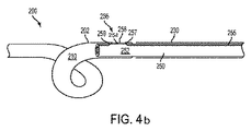
図4bに示される代替実施形態では、ワイヤ255が、管210の壁を通して進行し、管210の外部202を越えて延在し、管210内の内管250に添着する代わりに、ワイヤ255は、ワイヤ255に対して法線であって、管210の管腔内にある、別個のワイヤ区画254にわたって継続してもよい。別個のワイヤ区画254は、ワイヤ255の通過のための小面積および内管252の通過のための大面積を提供しながら、管210の壁に融合されてもよい。ワイヤ255は、別個のワイヤ区画254にわたってその経路を継続し、管210の管腔内に全体的に留まり、第2の角度付けられた区分259を完成し、内管250の管腔252の中に戻ってもよい。
In the alternative embodiment shown in FIG. 4b, instead of the
図5a−5bは、例示的実施形態による、管310内のワイヤ350の詳細な上部および側面図を示す。管310は、図1−4を参照して説明される管110または210と同一形態をとってもよく、またはそれに形態が類似してもよい。着脱可能部分330および内管350もまた示され、図1−4を参照して説明される着脱可能部分130または230および内管150または250と同一形態をとってもよく、またはそれに形態が類似してもよい。図5a−5bに示される実施形態では、金属バンドを備える、ワイヤ355は、着脱可能部分330を管310に除去可能に添着するために使用されてもよい。ワイヤ355の係合部分356は、カテーテル300の内壁305の中に係合するように示される。係合部分356は、残りのワイヤ355の表面の上方に延在する、凸、隆起、または他の突出表面を備えてもよい。
5a-5b show detailed top and side views of
図6は、例示的実施形態による、カテーテル400内のワイヤ450の詳細な断面側面図を示す。カテーテル400は、図1−4を参照して説明されるカテーテル100または200と同一形態をとってもよく、またはそれに形態が類似してもよい。着脱可能部分430もまた示され、図1−4を参照して説明される着脱可能部分130または230と同一形態をとってもよい。
FIG. 6 shows a detailed cross-sectional side view of
内管450は、2つの管腔、すなわち、第1の管腔451および第2の管腔452を備えてもよい。第1の管腔451は、第1の管腔451を第2の管腔452から分離するための壁を備えてもよい。ワイヤ255またはワイヤ355のいずれかの形態をとり得る、ワイヤ455は、第1の管腔451を通して介挿し、したがって、第2の管腔452に干渉しないように、管腔451内で隔離されてもよい。第2の管腔452は、ワイヤガイドまたはステント直線化管腔としての役割を果たしてもよい。内管450の二重管腔特徴は、管腔451内に位置するワイヤ455を分断させるリスクなく、ワイヤガイドまたはステント直線化装置等のデバイスツール類のために使用されるための隔離されたアクセス経路(第2の管腔452)の使用を可能にする。第1の管腔451は、患者内へのカテーテルの埋込の間および介入中のカテーテルツール類の対応する交換の間、ワイヤ455の外れに対する保護安全対策を提供する。流体は、第1の管腔451および第2の管腔452の両方を介して、カテーテル400と内管450との間で交換されてもよい。
The
図7は、例示的実施形態による、カテーテル500の例示的着脱可能部分530の詳細な断面側面図を示す。カテーテル500は、図1−4を参照して説明されるカテーテル100または200と同一形態をとってもよく、もしくはそれに形態が類似してもよい。カテーテル500は、図1−4を参照して説明される管110または210と同一形態をとってもよく、もしくはそれに形態が類似してもよい、管510を備えてもよい。
FIG. 7 shows a detailed cross-sectional side view of an exemplary removable portion 530 of catheter 500, according to an exemplary embodiment. Catheter 500 may take the same form as
着脱可能部分530は、第1の管部分532と、第2の管部分534と、第1の管部分532から第2の管部分534への遷移部536とを備えてもよい。遷移部536は、階段形態をとってもよく、約90度の遷移を備えてもよい。管腔533は、示されるように、第1の管部分532および第2の管部分534の両方を通して延在してもよく、両方の部分を通して同一直径を備えてもよい。遷移部536は、カテーテル500の端部505と噛合または当接してもよい。第2の管部分534は、第1の管部分532より小さい直径を備え、カテーテル500の管腔内に嵌合するように定寸および成形される。着脱可能部分530のためのそのような設計は、例えば、内管150および250等の付加的内管を有することを不必要にする。
The removable portion 530 may include a
図8は、着脱可能部分が除去された後に残ったステント200の斜視図を示す。ステント200は、カテーテル100と同一管110を備え、第1のピグテール状丸まり部160および第2のピグテール状丸まり部170は、患者の身体内で手が触れられないままである。着脱可能部分130、内管150、および係止機構140は、除去されている。新しい端部210は、マーカー190となる。
FIG. 8 shows a perspective view of the
動作時、患者の右または左横腹が、どちらの腎臓がアクセスされるべきかに応じて、滅菌して準備される。静脈内鎮静剤が、使用される。小口径針が、腎臓の集尿系に穿通するために使用され、造影剤が注射され、集尿系全体の完全可視化を可能にする。中心部分が、最初に、小型の針で穿通され、次いで、より大型の針が、集尿系のより小さいがより安全な面積に穿通するために使用される。ガイドワイヤが、腎臓の集尿系の中に導通され、ピグテール状ドレイン、すなわち、腎瘻造設術用カテーテルが、留置され、背中に縫合され、外部排出のためのバッグに掛着される。 In operation, the patient's right or left flank is prepared to be sterilized, depending on which kidney is to be accessed. Intravenous sedation is used. A small caliber needle is used to penetrate the renal urine collection system and a contrast agent is injected, allowing full visualization of the entire urine collection system. The central portion is first pierced with a small needle and then a larger needle is used to penetrate a smaller but safer area of the urine collection system. A guide wire is routed into the renal urine collection system and a pigtail drain, ie, a nephrostomy catheter, is placed, sutured to the back, and hooked to a bag for external drainage.
いったん尿から出血がなくなると、患者は、呼び戻され、ワイヤが、カテーテルを通して腎臓の中に挿入され、カテーテルが、除去される。ワイヤは、尿管を通して膀胱の中に導通され(狭窄を横断して)、カテーテル100が、留置される。ピグテール状丸まり部160、170は、その適切な姿勢に丸められる。カテーテルは、典型的には、7〜10日間、患者内に留まり、その時点で、患者は、呼び戻される。
Once the urine is free of bleeding, the patient is recalled, a wire is inserted through the catheter and into the kidney, and the catheter is removed. The wire is conducted through the ureter into the bladder (across the stenosis) and the
本時点で、医師がカテーテル100をステント200に交換することを所望する場合、医師は、係止機構140を係止解除し、係止機構を除去し、内管150にアクセスするであろう。医師は、次いで、内管150がマーカー190を越えて引張され、もはや管110の中空部分内になくなるまで、管110の中空部分を通して内管150を第1の端部112に向かって手動で引張するであろう。
At this point, if the physician desires to replace the
図3−7を参照して説明されるようなワイヤが使用される、別の例示的実施形態では、医師は、最初に、ワイヤ255、355、455、または555等のワイヤとの接続を維持する係止機構を解放するであろう。ワイヤは、例えば、キャップの旋回解除等の方法を使用して解放されてもよい。そのような例示的実施形態では、旋回解除式キャップ(近位ルアーハブにおいてワイヤに取り付けられている)は、キャップをハブから引き離し、ワイヤを内管(例えば、内管250、350、450)から完全に抜去することによって、ワイヤをカテーテル(例えば、カテーテル310および400)から係脱させる。いったんワイヤが除去されると、着脱可能部分(例えば、着脱可能部分330および530)および内管は、ここで、患者の身体から完全に抜去され、カテーテルをステント(例えば、ステント200)に変換し得る。
In another exemplary embodiment where a wire as described with reference to FIGS. 3-7 is used, the physician first maintains a connection with a wire such as
いったん内管150が管110から除去されると、着脱可能部分130は、もはや管110に取り付けられておらず、着脱可能部分130および内管150は両方とも、患者の身体から除去され得る。いったん着脱可能部分130および内管150が除去されると、カテーテル100は、図3に示されるようなステント200になる。これは、典型的には、泌尿器科医が膀胱を通して作業することによって留置されるであろうものと同一タイプのステントである。ステント200は、ここで、マーカー190に位置する、新しい端部210を備える。
Once the
変換可能腎尿管用カテーテルが使用され得る実施例は、患者が尿管閉塞を有し、水腎症(腎臓の集尿系の拡張)および水尿管症(尿管の拡張)を呈する状況である。患者は、横腹を通して集尿系の中に、そこから尿管を通して膀胱の中にデバイスが挿入される。デバイスは、尿から感染症または出血がなくなるまで、外部排出のために開放されたままとなるであろう。尿が清浄されると、変換可能腎尿管用カテーテル100の外部部分は、取り外され、カテーテルを内部ステントに変換するであろう。本時点以降、ステントは、直接、腎臓から膀胱に尿を排出するであろう。内部ステントは、除去または交換される準備ができるまで、定位置に留まるであろう。
An example where a convertible renal ureteral catheter may be used is in a situation where the patient has ureteral obstruction and exhibits hydronephrosis (dilatation of the renal urinary collection system) and hydroureteropathy (dilation of the ureter). is there. The patient is inserted through the flank into the urine collection system and from there through the ureter into the bladder. The device will remain open for external drainage until there is no infection or bleeding from the urine. When the urine is cleaned, the outer portion of the convertible renal
別の使用実施例は、患者が、最近、腎臓結石を通過させ、尿管が、一時的に、炎症し、閉塞されているときである。変換可能腎尿管用カテーテルは、前述と同一様式で挿入される。しかしながら、本状況では、カテーテルは、炎症が改善するまで、一時的に、留置される。いったんこれが確認されると、カテーテル全体が、蛍光透視下で造影剤注射を用いて、横腹から引き出すことによって除去される。本状況では、着脱可能部分は、取り外されない。しかしながら、カテーテルはまた、内部ステントとして定位置に残され、着脱可能部分は、臨床上の必要性に応じて、除去されてもよい。 Another use example is when a patient has recently passed a kidney stone and the ureter is temporarily inflamed and obstructed. The convertible renal ureteral catheter is inserted in the same manner as described above. However, in this situation, the catheter is temporarily placed until the inflammation has improved. Once this is confirmed, the entire catheter is removed by withdrawal from the flank using contrast agent injection under fluoroscopy. In this situation, the removable part is not removed. However, the catheter may also be left in place as an internal stent and the removable part may be removed depending on clinical needs.
別の使用実施例は、患者が、外傷、器具類、結石除去、癌、または別の理由に起因して、尿管からの漏出を有し、内部および外部尿迂回路が必要であるときである。この場合、変換可能腎尿管用カテーテル100は、患者内に留置され、尿は、外部に排出させられる。漏出に改善が認められ、カテーテルが、着脱可能部分130を除去することによって、内部ステントに変換されると、内部迂回路は、より長期間の間、可能にされる。ステント500は、漏出が解決された後、後に除去されるであろう。
Another use example is when a patient has leakage from the ureter due to trauma, instrumentation, calculus removal, cancer, or for other reasons, and internal and external urinary diversions are required. is there. In this case, the convertible renal
したがって、ある変更が、本発明の精神および範囲から逸脱することなく、前述の構造に行われ得ることが分かるであろう。前述の説明に含有される、または付随の図面に図示される事柄は全て、限定的意味ではなく、例証として解釈されるものであることが意図される。
Thus, it will be appreciated that certain changes may be made to the structure described above without departing from the spirit and scope of the invention. It is intended that all matter contained in the foregoing description or illustrated in the accompanying drawings shall be interpreted in an illustrative and not restrictive sense.
Claims (12)
円筒壁、第1の端部、第2の端部、前記第1の端部近傍の第1の保定特徴、および前記第2の端部近傍の第2の保定特徴を備える管と、
着脱可能部分であって、前記着脱可能部分は、患者の身体の内側から前記患者の身体の外側まで延在し、前記着脱可能部分は、前記第2の端部において、前記管と流体連通し、かつ、前記管に除去可能に取付可能である、着脱可能部分と、
少なくとも1つの管腔を備える内管であって、前記内管は、前記管および前記着脱可能部分の両方の中に除去可能に挿入可能である、内管と、
前記内管の前記少なくとも1つの管腔の中の管腔の少なくとも一部を通して延在するワイヤと
を備え、
前記ワイヤの一部は、前記管に取り付けられ、
前記着脱可能部分は、前記ワイヤを除去することによって前記管から取り外され、その結果、前記管がステントになる、カテーテル。 A catheter,
Cylindrical wall, a first end, a second end, said first end portion first holding constant features in the vicinity, and the Ru with a second holding constant feature of the second end portion tube,
A detachable part, wherein the detachable part extends from the inside of the patient's body to the outside of the patient's body, and the detachable part is in fluid communication with the tube at the second end. And a removable part that can be removably attached to the tube;
An inner tube comprising at least one lumen, wherein the inner tube is removably insertable into both the tube and the removable portion;
And a wire extending through at least a portion of the lumen in said at least one lumen of the inner tube,
A portion of the wire is attached to the tube ;
The catheter wherein the removable portion is removed from the tube by removing the wire, so that the tube becomes a stent .
管であって、前記管は、管腔、第1の端部、第2の端部、前記第1の端部近傍の第1の保定特徴、および前記第2の端部近傍の第2の保定特徴を備える、管と、
着脱可能部分であって、前記着脱可能部分は、患者の身体の内側から前記患者の身体の外側まで延在し、前記着脱可能部分は、前記管の中に挿入可能であり、かつ、挿入されると前記管の前記管腔と流体連通する管腔を備える、着脱可能部分と、
前記着脱可能部分および前記管の少なくとも一部を通して延在するワイヤと
を備え、
いったん前記ワイヤが前記管から除去されると、前記着脱可能部分は、前記管から除去可能であり、その結果、前記管がステントになる、カテーテル。 A Luke catheters be converted to the stent,
A tube, the tube comprising a lumen, a first end, a second end, a first retaining feature near the first end, and a second near the second end A tube with a retaining feature; and
A removable part, the removable part extending from the inside of the patient's body to the outside of the patient's body, the removable part being insertable into and inserted into the tube A removable portion comprising a lumen in fluid communication with the lumen of the tube;
And a wire extending through at least a portion of said removable portion and said tube,
Once the wire is removed from the tube, wherein the removable portion is Ri removable der from the tube, as a result, the tube is a stent, a catheter.
Applications Claiming Priority (3)
| Application Number | Priority Date | Filing Date | Title |
|---|---|---|---|
| US14/159,221 US9387312B2 (en) | 2008-09-15 | 2014-01-20 | Convertible nephroureteral catheter |
| US14/159,221 | 2014-01-20 | ||
| PCT/US2014/063758 WO2015108609A1 (en) | 2014-01-20 | 2014-11-03 | Convertible nephroureteral catheter |
Publications (3)
| Publication Number | Publication Date |
|---|---|
| JP2017502818A JP2017502818A (en) | 2017-01-26 |
| JP2017502818A5 JP2017502818A5 (en) | 2017-12-07 |
| JP6469134B2 true JP6469134B2 (en) | 2019-02-13 |
Family
ID=53543313
Family Applications (1)
| Application Number | Title | Priority Date | Filing Date |
|---|---|---|---|
| JP2016564943A Active JP6469134B2 (en) | 2014-01-20 | 2014-11-03 | Convertible renal ureteral catheter |
Country Status (4)
| Country | Link |
|---|---|
| EP (1) | EP3096716B1 (en) |
| JP (1) | JP6469134B2 (en) |
| CN (2) | CN106029012B (en) |
| WO (1) | WO2015108609A1 (en) |
Families Citing this family (5)
| Publication number | Priority date | Publication date | Assignee | Title |
|---|---|---|---|---|
| US9387312B2 (en) | 2008-09-15 | 2016-07-12 | Brightwater Medical, Inc. | Convertible nephroureteral catheter |
| US9956100B2 (en) | 2009-09-15 | 2018-05-01 | Brightwater Medical, Inc. | Systems and methods for coupling and decoupling a catheter |
| CN106714730B (en) | 2014-08-12 | 2019-04-16 | 布赖特沃特医疗公司 | System and method for coupling and decoupling conduit |
| CA3062857A1 (en) * | 2017-05-14 | 2018-11-22 | Navigate Cardiac Structures, Inc. | Valved stent for orthotopic replacement of dysfunctional cardiac valve and delivery system |
| CN112294507B (en) * | 2020-11-02 | 2021-08-17 | 许传兵 | Ureteral stent implantation equipment |
Family Cites Families (18)
| Publication number | Priority date | Publication date | Assignee | Title |
|---|---|---|---|---|
| US4913683A (en) * | 1988-07-05 | 1990-04-03 | Medical Engineering Corporation | Infusion stent system |
| US4957479A (en) * | 1988-10-17 | 1990-09-18 | Vance Products Incorporated | Indwelling ureteral stent placement apparatus |
| CN2128148Y (en) * | 1992-06-25 | 1993-03-17 | 夏志恬 | Internal supporter drainage-tube for ureter |
| AU6495794A (en) * | 1993-03-30 | 1994-10-24 | Instent Inc. | Temporary stent system |
| US6835185B2 (en) * | 1998-12-21 | 2004-12-28 | Micrus Corporation | Intravascular device deployment mechanism incorporating mechanical detachment |
| CN2408894Y (en) * | 2000-01-06 | 2000-12-06 | 马建新 | Implantation type ureter internal supporter |
| WO2001076675A2 (en) * | 2000-04-11 | 2001-10-18 | Scimed Life Systems, Inc. | Reinforced retention structures |
| US20040073283A1 (en) * | 2001-12-21 | 2004-04-15 | Ewers Richard C. | Stent delivery system and method |
| US7789915B2 (en) * | 2005-08-31 | 2010-09-07 | Vance Products Incorporated | Stent for implantation |
| US7550012B2 (en) * | 2005-08-31 | 2009-06-23 | Cook Ireland Limited | Stent for implantation |
| US20070112420A1 (en) * | 2005-11-14 | 2007-05-17 | Duke Fiduciary Llc | Detachable therapeutic tube |
| US8034094B2 (en) * | 2008-06-11 | 2011-10-11 | Olympus Medical Systems Corp. | Stent delivery system and stent delivery method |
| US8657884B2 (en) * | 2008-09-15 | 2014-02-25 | Harry R. Smouse | Convertible nephroureteral catheter |
| CN201624817U (en) * | 2009-08-13 | 2010-11-10 | 王晓 | Ureteral catheter guide wire |
| US8523932B2 (en) * | 2010-05-24 | 2013-09-03 | Cook Medical Technologies Llc | Variable diameter trigger wire |
| EP2640325B1 (en) * | 2010-11-19 | 2016-07-20 | Boston Scientific Scimed, Inc. | Rapid exchange stent delivery system |
| JP4913251B1 (en) * | 2011-05-24 | 2012-04-11 | 株式会社カテックス | Stent delivery system |
| CN102579171B (en) * | 2012-03-05 | 2015-03-18 | 中国人民解放军第三军医大学第二附属医院 | Ureteral stent device |
-
2014
- 2014-11-03 JP JP2016564943A patent/JP6469134B2/en active Active
- 2014-11-03 CN CN201480076309.7A patent/CN106029012B/en active Active
- 2014-11-03 EP EP14878890.4A patent/EP3096716B1/en active Active
- 2014-11-03 WO PCT/US2014/063758 patent/WO2015108609A1/en active Application Filing
- 2014-11-03 CN CN202010300982.1A patent/CN111671984A/en active Pending
Also Published As
| Publication number | Publication date |
|---|---|
| EP3096716A1 (en) | 2016-11-30 |
| CN106029012B (en) | 2020-05-08 |
| WO2015108609A1 (en) | 2015-07-23 |
| JP2017502818A (en) | 2017-01-26 |
| CN111671984A (en) | 2020-09-18 |
| EP3096716A4 (en) | 2017-10-11 |
| EP3096716B1 (en) | 2019-01-09 |
| CN106029012A (en) | 2016-10-12 |
Similar Documents
| Publication | Publication Date | Title |
|---|---|---|
| US11439493B2 (en) | Convertible nephroureteral catheter | |
| US8657884B2 (en) | Convertible nephroureteral catheter | |
| AU2003239098B2 (en) | Drainage catheter | |
| JP6469134B2 (en) | Convertible renal ureteral catheter | |
| US8292872B2 (en) | Distal wire stop having adjustable handle | |
| EP1740252B1 (en) | Distal wire stop | |
| EP1942971B1 (en) | Catheter for implantation of Stents | |
| US20110301684A1 (en) | System and method for performing angiography and stenting | |
| JP2017534326A (en) | Catheter system for ureteral catheter delivery | |
| JPH11500939A (en) | Braidless guide catheter | |
| US20060200079A1 (en) | Drainage catheter | |
| JP2015526259A (en) | Apparatus and method for treating vascular disease | |
| JP2005312898A (en) | Improved stent | |
| US20160008531A1 (en) | Dual lumen cannula for artificial lung and right ventricular assist device | |
| US20230248946A1 (en) | Low Profile Lumen Access Catheter | |
| US20150335415A1 (en) | Intravenous filter with guidewire and catheter access guide | |
| JP2017502818A5 (en) | ||
| US20170014156A1 (en) | Self-dilating catheter introducer with obturator and method of use | |
| US20140121751A1 (en) | Cannula attachment in endoluminal delivery devices | |
| US20210085917A1 (en) | Percutaneous Nephrostomy System | |
| EP2858709B1 (en) | Stent pusher assembly | |
| US20230024336A1 (en) | All-purpose Drainage Catheter | |
| TW202400089A (en) | Systems and methods for the endovascular treatment of hydrocephalus and elevated intracranial pressure | |
| WO2021173842A1 (en) | Isolating drainage catheter | |
| JP2023527594A (en) | Ureteral bypass devices and ureteral bypass procedures |
Legal Events
| Date | Code | Title | Description |
|---|---|---|---|
| A521 | Request for written amendment filed |
Free format text: JAPANESE INTERMEDIATE CODE: A523 Effective date: 20171030 |
|
| A621 | Written request for application examination |
Free format text: JAPANESE INTERMEDIATE CODE: A621 Effective date: 20171030 |
|
| A131 | Notification of reasons for refusal |
Free format text: JAPANESE INTERMEDIATE CODE: A131 Effective date: 20180920 |
|
| A977 | Report on retrieval |
Free format text: JAPANESE INTERMEDIATE CODE: A971007 Effective date: 20180921 |
|
| A521 | Request for written amendment filed |
Free format text: JAPANESE INTERMEDIATE CODE: A523 Effective date: 20181030 |
|
| TRDD | Decision of grant or rejection written | ||
| A01 | Written decision to grant a patent or to grant a registration (utility model) |
Free format text: JAPANESE INTERMEDIATE CODE: A01 Effective date: 20181220 |
|
| A61 | First payment of annual fees (during grant procedure) |
Free format text: JAPANESE INTERMEDIATE CODE: A61 Effective date: 20190115 |
|
| R150 | Certificate of patent or registration of utility model |
Ref document number: 6469134 Country of ref document: JP Free format text: JAPANESE INTERMEDIATE CODE: R150 |
|
| S111 | Request for change of ownership or part of ownership |
Free format text: JAPANESE INTERMEDIATE CODE: R313113 |
|
| R350 | Written notification of registration of transfer |
Free format text: JAPANESE INTERMEDIATE CODE: R350 |
|
| R250 | Receipt of annual fees |
Free format text: JAPANESE INTERMEDIATE CODE: R250 |
|
| R250 | Receipt of annual fees |
Free format text: JAPANESE INTERMEDIATE CODE: R250 |
|
| R250 | Receipt of annual fees |
Free format text: JAPANESE INTERMEDIATE CODE: R250 |