JP6468995B2 - Gas separation method and equipment by pressure swing adsorption method - Google Patents
Gas separation method and equipment by pressure swing adsorption method Download PDFInfo
- Publication number
- JP6468995B2 JP6468995B2 JP2015240723A JP2015240723A JP6468995B2 JP 6468995 B2 JP6468995 B2 JP 6468995B2 JP 2015240723 A JP2015240723 A JP 2015240723A JP 2015240723 A JP2015240723 A JP 2015240723A JP 6468995 B2 JP6468995 B2 JP 6468995B2
- Authority
- JP
- Japan
- Prior art keywords
- gas
- adsorption
- cleaning
- adsorption tower
- adsorbent packed
- Prior art date
- Legal status (The legal status is an assumption and is not a legal conclusion. Google has not performed a legal analysis and makes no representation as to the accuracy of the status listed.)
- Active
Links
- 238000001179 sorption measurement Methods 0.000 title claims description 165
- 238000000034 method Methods 0.000 title claims description 122
- 238000000926 separation method Methods 0.000 title claims description 72
- 239000003463 adsorbent Substances 0.000 claims description 177
- 238000004140 cleaning Methods 0.000 claims description 60
- 239000002994 raw material Substances 0.000 claims description 52
- CURLTUGMZLYLDI-UHFFFAOYSA-N Carbon dioxide Chemical compound O=C=O CURLTUGMZLYLDI-UHFFFAOYSA-N 0.000 claims description 17
- 238000003795 desorption Methods 0.000 claims description 13
- 238000005406 washing Methods 0.000 claims description 11
- 229910002092 carbon dioxide Inorganic materials 0.000 claims description 8
- 239000001569 carbon dioxide Substances 0.000 claims description 8
- 238000007599 discharging Methods 0.000 claims description 7
- 239000006227 byproduct Substances 0.000 claims description 6
- 239000007789 gas Substances 0.000 description 412
- 238000011084 recovery Methods 0.000 description 15
- 230000000052 comparative effect Effects 0.000 description 6
- 238000009826 distribution Methods 0.000 description 6
- 230000007423 decrease Effects 0.000 description 5
- 239000012535 impurity Substances 0.000 description 5
- 238000009434 installation Methods 0.000 description 5
- 229910021536 Zeolite Inorganic materials 0.000 description 2
- HNPSIPDUKPIQMN-UHFFFAOYSA-N dioxosilane;oxo(oxoalumanyloxy)alumane Chemical compound O=[Si]=O.O=[Al]O[Al]=O HNPSIPDUKPIQMN-UHFFFAOYSA-N 0.000 description 2
- 230000000694 effects Effects 0.000 description 2
- 238000005192 partition Methods 0.000 description 2
- 239000010457 zeolite Substances 0.000 description 2
- 235000011089 carbon dioxide Nutrition 0.000 description 1
- 238000002485 combustion reaction Methods 0.000 description 1
- 238000011109 contamination Methods 0.000 description 1
- 238000004519 manufacturing process Methods 0.000 description 1
- 238000012856 packing Methods 0.000 description 1
- 230000035699 permeability Effects 0.000 description 1
- 238000007670 refining Methods 0.000 description 1
- 239000000126 substance Substances 0.000 description 1
Images


Description
本発明は、圧力スイング吸着法により原料ガス(混合ガス)から特定ガス成分を分離回収する(例えば、製鉄所副生ガスから二酸化炭素ガスを分離回収する)ためのガス分離方法及びガス分離設備に関するものである。 The present invention relates to a gas separation method and a gas separation facility for separating and recovering a specific gas component from a raw material gas (mixed gas) by a pressure swing adsorption method (for example, separating and recovering carbon dioxide gas from an ironworks byproduct gas). Is.
従来、原料ガス(混合ガス)に含まれる特定のガス成分を分離回収する方法として、圧力スイング吸着法(以下、PSA法という)が広く用いられている(例えば、特許文献1)。PSA法は、吸着剤に対するガス成分の吸着量が、ガス種及びその分圧によって異なることを利用した分離方法であり、吸着剤に特定ガス成分を吸着させる工程(吸着工程)、吸着剤への特定ガス成分の吸着率を高める工程(洗浄工程)、及び吸着した特定ガス成分を吸着剤から脱着させてガスを回収する工程(脱着工程)を含む。このPSA法は種々の分野に適用されているが、原料ガスに含まれる一成分を吸着させることにより、高濃度のガスを製造する方法として利用されることが多い。例えば、ボイラー排ガスや燃焼排ガスなどを原料ガスとして、PSA法により化学原料やドライアイス用の二酸化炭素ガスが製造されている。 Conventionally, a pressure swing adsorption method (hereinafter referred to as PSA method) has been widely used as a method for separating and recovering a specific gas component contained in a source gas (mixed gas) (for example, Patent Document 1). The PSA method is a separation method that utilizes the fact that the amount of gas component adsorbed on the adsorbent varies depending on the gas species and its partial pressure, and a process for adsorbing a specific gas component on the adsorbent (adsorption process), A step of increasing the adsorption rate of the specific gas component (cleaning step), and a step of desorbing the adsorbed specific gas component from the adsorbent and recovering the gas (desorption step). Although this PSA method is applied to various fields, it is often used as a method for producing a high-concentration gas by adsorbing one component contained in a raw material gas. For example, chemical raw materials and carbon dioxide gas for dry ice are produced by the PSA method using boiler exhaust gas or combustion exhaust gas as raw material gas.
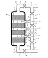
図10は、PSA法により原料ガスから二酸化炭素ガス(CO2)を分離回収する従来設備を示している。このPSA設備30は3塔の吸着塔41〜43を備えており、これら吸着塔41〜43には吸着剤(例えば、ゼオライトなど)が充填されている。ここでは、吸着塔41が吸着工程、吸着塔42が洗浄工程、吸着塔43が脱着工程をそれぞれ行っているものとして、原料ガス(例えば、高炉ガス)からCO2を分離回収する方法について説明する。なお、図中のV1〜V12はガス配管に設けられた開閉バルブであり、白抜きのバルブは開状態を、黒塗りのバルブは閉状態をそれぞれ示している。
FIG. 10 shows a conventional facility for separating and recovering carbon dioxide gas (CO 2 ) from raw material gas by the PSA method. The
吸着工程が行われている吸着塔41では、バルブV1,V4が開放され、ブロワー45により原料ガス導入管44を通じて原料ガスC0が導入される。この原料ガスC0は、吸着塔41内の吸着剤にCO2が吸着され、そのオフガスC1がオフガス排気管47により排出される。この段階では、吸着塔41内でCO2は濃縮されるものの、一般的には十分な濃度は得られていない。脱着工程が行われている吸着塔43では、バルブV11が開放され、吸着されているCO2を吸着剤から脱着させ、濃縮されたCO2(ガスC2)が真空ポンプ46により排出される。この高濃度CO2(ガスC2)の一部は、回収ガスC3として回収ガス排気管48により排出され、残りは、洗浄ガス供給管49により洗浄ガスC4として洗浄工程にある吸着塔42に導入される。洗浄工程にある吸着塔42では、バルブV6,V8が開放され、洗浄ガスC4が塔内に導入されて、吸着塔内の不要なガス成分がオフガスC5としてオフガス排気管47から排出される。この洗浄工程により、少量残留しているCO2以外のガス成分が、吸着剤から脱離されて吸着搭42から排出され、これにより、吸着塔42内には高濃度のCO2が残留することになる。上記の吸着工程、洗浄工程及び脱着工程を各吸着塔が順次行うことにより、原料ガスC0から高濃度のCO2を回収ガスC3として連続的に分離回収することができる。
In the
PSA法ではガス分離に要する電力が大きいため、ガス分離コストの削減には、PSAにおける電力消費量の削減が必要である。特に製鉄所副生ガスからCO2を分離回収する場合、製鉄所副生ガスはCO2濃度が低い(例えば、高炉ガスでは22vol%程度)ためCO2分離に要する電力消費が大きい。しかしながら、図10に示すような従来の吸着塔を用いたPSA設備では、ガス流通方法に制約があるため電力消費量の削減が難しい。 Since power required for gas separation is large in the PSA method, it is necessary to reduce power consumption in the PSA in order to reduce the gas separation cost. In particular, when CO 2 is separated and recovered from the ironworks byproduct gas, the ironworks byproduct gas has a low CO 2 concentration (for example, about 22 vol% in the blast furnace gas), so that power consumption required for CO 2 separation is large. However, in the PSA facility using the conventional adsorption tower as shown in FIG. 10, it is difficult to reduce the power consumption because there are restrictions on the gas distribution method.
すなわち、高炉ガスのような多成分混合ガスを原料ガスとする場合、吸着剤充填層にガスを流通する過程でガス組成が変化するため吸着剤へのガス吸着状態は一様にはならない。特に吸着剤充填層の上部領域は、下部領域を流通した後のCO2が少ないオフガスが流通するため、CO2吸着量が低下する。また、吸着剤充填層の下部領域においてCO2が吸着されることにより、オフガス中のCO2以外のガス成分(N2、CO等)の分圧が増加するので、上部領域においてCO2以外のガス成分の吸着量が増加し、当該領域での回収CO2純度が低下する。このように従来の吸着塔では、ガスが吸着剤充填層を流通する上での本質的な制約から、不可避的に吸着剤充填層内でCO2吸着量や回収CO2純度に分布を生じ、このため、少ない電力消費量で効率的なガス分離回収を行うことが難しい。 That is, when a multi-component mixed gas such as blast furnace gas is used as a raw material gas, the gas composition changes in the process of flowing the gas through the adsorbent packed bed, so the gas adsorption state on the adsorbent is not uniform. In particular, in the upper region of the adsorbent packed bed, the off-gas with a small amount of CO 2 after flowing through the lower region flows, so that the CO 2 adsorption amount decreases. Further, since the CO 2 is adsorbed in the lower region of the adsorbent filling layer, since the partial pressure of CO 2 other than the gas component in the off-gas (N 2, CO, etc.) is increased, other than CO 2 in the upper region The adsorption amount of the gas component increases, and the recovered CO 2 purity in the region decreases. Thus, in the conventional adsorption tower, due to the essential restrictions on the gas flowing through the adsorbent packed bed, the distribution of CO 2 adsorption amount and recovered CO 2 purity is inevitably generated in the adsorbent packed bed, For this reason, it is difficult to perform efficient gas separation and recovery with low power consumption.
したがって本発明の目的は、以上のような従来技術の課題を解決し、圧力スイング吸着法によるガス分離において、目的ガス成分の分離回収量を高めることができるガス分離方法及び設備を提供することにある。また、本発明のさらなる目的は、圧力スイング吸着法によるガス分離を少ない電力消費量で効率的に行うことができるガス分離方法及び設備を提供することにある。 Accordingly, an object of the present invention is to provide a gas separation method and equipment capable of solving the above-described problems of the prior art and increasing the separation and recovery amount of the target gas component in the gas separation by the pressure swing adsorption method. is there. A further object of the present invention is to provide a gas separation method and equipment capable of efficiently performing gas separation by the pressure swing adsorption method with low power consumption.
上記課題を解決するための本発明の要旨は以下のとおりである。
[1]圧力スイング吸着法により原料ガスから特定ガス成分を分離回収するためのガス分離設備において、塔下端のガス入口部(1)と塔上端のガス出口部(2)との間に、複数の吸着剤充填層(3)を吸着剤が充填されない空間部(4)を介在させて直列状に設けるとともに、空間部(4)からガスを導入又は排出するガス出入口(5)を設けた吸着塔(A)と、該吸着塔(A)のガス入口部(1)とガス出口部(2)とガス出入口(5)に通じるガス流路(B)を備え、該ガス流路(B)に設けられる複数の開閉弁(6)による流路の切り替えにより、1つ以上の吸着剤充填層(3)をバイパスして吸着塔(A)内にガスを流通させ得るようにしたことを特徴とする圧力スイング吸着法によるガス分離設備。
The gist of the present invention for solving the above problems is as follows.
[1] In a gas separation facility for separating and recovering a specific gas component from a raw material gas by a pressure swing adsorption method, a plurality of components are provided between a gas inlet (1) at the bottom of the tower and a gas outlet (2) at the top of the tower. The adsorbent packed bed (3) is provided in series with the space (4) not filled with the adsorbent, and the gas inlet / outlet (5) for introducing or discharging gas from the space (4) is provided. A gas channel (B) communicating with a tower (A), a gas inlet part (1), a gas outlet part (2) and a gas inlet / outlet (5) of the adsorption tower (A), the gas channel (B) By switching the flow path with a plurality of on-off valves (6) provided in the gas, one or more adsorbent packed beds (3) can be bypassed to allow gas to flow through the adsorption tower (A). Gas separation equipment by pressure swing adsorption method.
[2]上記[1]のガス分離設備において、ガス流路(B)が、ガス入口部(1)に接続されたガス配管(7)と、ガス出口部(2)に接続されたガス配管(8)と、一端がガス配管(7)の途中に接続(11)され、他端がガス配管(8)の途中に接続(12)されたガス配管(9)と、一端がガス出入口(5)に接続され、他端がガス配管(9)の途中に接続(13)されたガス配管(10)を有することを特徴とする圧力スイング吸着法によるガス分離設備。 [2] In the gas separation facility of [1], the gas flow path (B) includes a gas pipe (7) connected to the gas inlet part (1) and a gas pipe connected to the gas outlet part (2). (8), one end connected to the gas pipe (7) (11) and the other end connected to the gas pipe (8) (12), and one end connected to the gas inlet ( 5) Gas separation equipment by pressure swing adsorption method, characterized in that it has a gas pipe (10) connected to (13) in the middle of the gas pipe (9).
[3]圧力スイング吸着法により原料ガスから特定ガス成分を分離回収するためのガス分離方法において、上記[1]又は[2]のガス分離設備を用い、原料ガス又は洗浄ガスを1つ以上の吸着剤充填層(3)をバイパスして吸着塔(A)内に流通させることを特徴とする圧力スイング吸着法によるガス分離方法。
[4]上記[3]のガス分離方法において、原料ガス又は洗浄ガスを吸着塔(A)内に流通させる1つの工程中、一部の時間帯でのみ、1つ以上の吸着剤充填層(3)をバイパスして吸着塔(A)内に原料ガス又は洗浄ガスを流通させることを特徴とする圧力スイング吸着法によるガス分離方法。
[3] In a gas separation method for separating and recovering a specific gas component from a raw material gas by a pressure swing adsorption method, the gas separation facility of [1] or [2] is used, and one or more raw material gases or cleaning gases are used. A gas separation method by a pressure swing adsorption method, wherein the adsorbent packed bed (3) is bypassed and circulated in the adsorption tower (A).
[4] In the gas separation method of the above [3], one or more adsorbent packed beds (only in a part of time zone) during one step of flowing the raw material gas or the cleaning gas into the adsorption tower (A) ( 3) A gas separation method by a pressure swing adsorption method, wherein the raw material gas or the cleaning gas is circulated in the adsorption tower (A) by bypassing 3).
[5]上記[3]又は[4]のガス分離方法において、原料ガス又は洗浄ガスを吸着塔(A)内に流通させる1つの工程中、原料ガス又は洗浄ガスをバイパスさせる吸着剤充填層(3)を変更することを特徴とする圧力スイング吸着法によるガス分離方法。
[6]上記[5]のガス分離方法において、当該工程が終了するまでに、吸着塔(A)内の全部の吸着剤充填層(3)に対する原料ガス又は洗浄ガスの流通がなされることを特徴とする圧力スイング吸着法によるガス分離方法。
[5] In the gas separation method of [3] or [4] above, an adsorbent packed bed that bypasses the source gas or the cleaning gas during one step of circulating the source gas or the cleaning gas into the adsorption tower (A) ( (3) A gas separation method by a pressure swing adsorption method, wherein the method is changed.
[6] In the gas separation method of the above [5], the raw material gas or the cleaning gas is circulated to all the adsorbent packed beds (3) in the adsorption tower (A) before the process is completed. A gas separation method by a pressure swing adsorption method.
本発明によれば、吸着塔(A)内に複数の吸着剤充填層(3)が多段に設けられ、原料ガス又は洗浄ガスを1つ以上の任意の吸着剤充填層(3)をバイパスして吸着塔(A)内に流通させることができるため、1つの工程中で、原料ガス又は洗浄ガスを流通させる吸着剤充填層(3)を適宜選択・変更することにより、吸着塔(A)内の吸着剤充填層全体においてガス吸着量や回収ガス純度に分布が生じることが防止できる。このため、圧力スイング吸着法によるガス分離を効率的に行うことができ、目的ガス成分の回収量を高めることができる。
さらに、圧力スイング吸着法によるガス分離を少ない電力消費量で効率的に行うことができ、特に、本発明法を洗浄工程に適用した場合にその効果が大きい。これにより、例えば、製鉄所副生ガス中の二酸化炭素ガスの分離回収において、二酸化炭素ガス回収量の増加及び回収に要する電力消費量の低減化が可能となる。
According to the present invention, a plurality of adsorbent packed beds (3) are provided in multiple stages in the adsorption tower (A), and the raw material gas or the cleaning gas bypasses one or more arbitrary adsorbent packed beds (3). The adsorbent tower (A) can be circulated in the adsorption tower (A) by appropriately selecting and changing the adsorbent packed bed (3) through which the raw material gas or the cleaning gas is circulated in one process. It is possible to prevent the gas adsorption amount and the recovered gas purity from being distributed over the entire adsorbent packed bed. For this reason, gas separation by the pressure swing adsorption method can be performed efficiently, and the recovery amount of the target gas component can be increased.
Furthermore, gas separation by the pressure swing adsorption method can be efficiently performed with a small amount of power consumption, and the effect is particularly great when the method of the present invention is applied to a cleaning process. Thereby, for example, in the separation and recovery of carbon dioxide gas in a steelworks byproduct gas, it is possible to increase the amount of carbon dioxide gas recovered and reduce the power consumption required for recovery.
本発明のガス分離設備は、圧力スイング吸着法により原料ガス(混合ガス)から特定ガス成分(目的ガス成分)を分離回収するためのガス分離設備である。
図1は、本発明のガス分離設備の一実施形態を示すものであり、ガス分離設備は吸着塔Aと、この吸着塔Aのガス導入・排出を行うガス流路Bを備えている。通常、吸着塔Aは複数基(一般に3基以上)設けられ、これら複数の吸着塔Aで吸着工程、洗浄工程、脱着工程が順次行われるとともに、常にいずれかの吸着塔Aで上記各工程が行われるようにしている。
The gas separation facility of the present invention is a gas separation facility for separating and recovering a specific gas component (target gas component) from a raw material gas (mixed gas) by a pressure swing adsorption method.
FIG. 1 shows an embodiment of a gas separation facility according to the present invention. The gas separation facility includes an adsorption tower A and a gas flow path B for introducing and discharging the gas from the adsorption tower A. Usually, a plurality of adsorption towers A (generally three or more) are provided, and the adsorption process, washing process, and desorption process are sequentially performed in the plurality of adsorption towers A, and each of the above processes is always performed in any of the adsorption towers A. To be done.
吸着塔Aの下端にはガス入口部1が、上端にはガス出口部2がそれぞれ設けられ、これらガス入口部1とガス出口部2との間には、複数の吸着剤充填層3が、吸着剤が充填されない空間部4を間に介在させて直列状(多段式)に設けられている。この実施形態では、2つの吸着剤充填層3a,3bが設けられている。吸着剤充填層3a,3b間には、空間部4からガスを導入又は排出するガス出入口5が設けられている。
なお、各吸着剤充填層3は、例えば、網状部材などのような通気性を有する仕切壁(図示せず)間に吸着剤が充填されたものであり、仕切壁を通じて吸着剤の充填層にガスが流通する。
A gas inlet portion 1 is provided at the lower end of the adsorption tower A, and a
In addition, each adsorbent packed
ガス流路Bを構成するガス配管は、吸着塔Aのガス入口部1とガス出口部2とガス出入口5に接続され、ガス流路Bはこれらガスの出入口と通じている。ガス流路Bの要所(複数箇所)には開閉弁6が設けられ、これら開閉弁6による流路の切り替えにより、1つ以上の任意の吸着剤充填層3(本実施形態では吸着剤充填層3a、吸着剤充填層3bのいずれか)をバイパスして吸着塔A内にガスを流通させ得るようにしている。
The gas pipe constituting the gas flow path B is connected to the gas inlet part 1, the
具体的には、ガス流路Bは、ガス入口部1に接続されたガス配管7と、ガス出口部2に接続されたガス配管8と、一端がガス配管7の途中に接続11され、他端がガス配管8の途中に接続12されたガス配管9と、一端がガス出入口5に接続され、他端がガス配管9の途中に接続13されたガス配管10で構成されている。そして、ガス配管7のうちガス入口部1と接続部11間の配管部分70に開閉弁6aが、ガス配管8のうちガス出口部2と接続部12間の配管部分80に開閉弁6bが、ガス配管9のうち接続部11と接続部13間の配管部分90に開閉弁6cが、ガス配管9のうち接続部12と接続部13間の配管部分91に開閉弁6dが、それぞれ設けられている。
Specifically, the gas flow path B includes a
このような構成によれば、開閉弁6a〜6dの開閉による流路の切り替えにより、吸着剤充填層3a又は吸着剤充填層3bをバイパスして吸着塔A内にガスを流通させることができる。
なお、図示しないが、図10のガス流路と同様に、ガス配管7は複数の分岐管に分岐し、その分岐管の1つは原料ガスの供給系に通じている。また、その他の分岐管は、他の吸着塔Aのガス配管に通じ、他の吸着塔Aで脱着された脱着ガスを洗浄ガスとして供給できるようにしている。この構成は、図2、図3の実施形態でも同様である。
According to such a configuration, the gas is circulated in the adsorption tower A by bypassing the adsorbent packed
Although not shown, the
吸着塔A内に設けられる吸着剤充填層3の層数に特別な制限はないが、層数が多いと開閉弁の配置や配管レイアウトなど設計上の制約も多くなるため、2〜4程度が適当である。
図2は、本発明のガス分離設備において4層の吸着剤充填層3を設けた実施形態を示すものである。
吸着塔Aのガス入口部1とガス出口部2との間には、4層の吸着剤充填層3A〜3Dが、吸着剤が充填されない空間部4A〜4Cを間に介在させて直列状(多段式)に設けられている。隣接する吸着剤充填層3間には、それぞれの空間部4A〜4Cからガスを導入又は排出するガス出入口5A〜5Cが設けられている。
There is no particular restriction on the number of adsorbent packed
FIG. 2 shows an embodiment in which four adsorbent packed
Between the gas inlet part 1 and the
本実施形態でも、ガス流路Bを構成するガス配管は、吸着塔Aのガス入口部1とガス出口部2とガス出入口5A〜5Cに接続され、ガス流路Bはこれらガスの出入口と通じている。ガス流路Bの要所(複数箇所)には開閉弁6が設けられ、これら開閉弁6による流路の切り替えにより、1つ以上の任意の吸着剤充填層3(例えば、吸着剤充填層3A〜3Dのいずれか、或いは吸着剤充填層3A+3B、吸着剤充填層3A+3B+3C、吸着剤充填層3C+3Dなど)をバイパスして吸着塔A内にガスを流通させ得るようにしている。
In the present embodiment, the gas pipe constituting a gas flow path B is connected to the gas inlet 1 and the
ガス流路Bを構成するガス配管は、ガス入口部1に接続されたガス配管7、ガス出口部2に接続されたガス配管8、一端がガス配管7の途中に接続11され、他端がガス配管8の途中に接続12されたガス配管9については、図1の実施形態と同様である。本実施形態のガス流路Bは、さらに、一端がガス出入口5Aに接続され、他端がガス配管9の途中に接続14されたガス配管10Aと、一端がガス出入口5Bに接続され、他端がガス配管9の途中に接続15されたガス配管10Bと、一端がガス出入口5Cに接続され、他端がガス配管9の途中に接続16されたガス配管10Cを有している。そして、ガス配管7のうちガス入口部1と接続部11間の配管部分70に開閉弁6Aが、ガス配管8のうちガス出口部2と接続部12間の配管部分80に開閉弁6Bが、ガス配管9のうち接続部11と接続部14間の配管部分92に開閉弁6Cが、ガス配管9のうち接続部14と接続部15間の配管部分93に開閉弁6Dが、ガス配管9のうち接続部15と接続部16間の配管部分94に開閉弁6Eが、ガス配管9のうち接続部16と接続部12間の配管部分95に開閉弁6Fが、ガス配管10Aに開閉弁6Gが、ガス配管10Bに開閉弁6Hが、ガス配管10Cに開閉弁6Iが、それぞれ設けられている。
このような構成によれば、開閉弁6A〜6Iの開閉による流路の切り替えにより、1つ以上の吸着剤充填層3をバイパスして吸着塔A内にガスを流通させることができる。
The gas pipe constituting the gas flow path B includes a
According to such a configuration, the gas can be circulated in the adsorption tower A by bypassing the one or more adsorbent packed
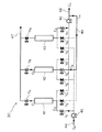
図3は、本発明のガス分離設備において3層の吸着剤充填層3を設けた実施形態を示すものである。
吸着塔Aのガス入口部1とガス出口部2との間には、3層の吸着剤充填層3E〜3Gが、吸着剤が充填されない空間部4D,4Eを間に介在させて直列状(多段式)に設けられている。隣接する吸着剤充填層3間には、それぞれの空間部4D,4Eからガスを導入又は排出するガス出入口5D,5Eが設けられている。
FIG. 3 shows an embodiment in which three adsorbent
Between the gas inlet 1 and the
本実施形態でも、ガス流路Bを構成するガス配管は、吸着塔Aのガス入口部1とガス出口部2とガス出入口5D,5Eに接続され、ガス流路Bはこれらガスの出入口と通じている。ガス流路Bの要所(複数箇所)には開閉弁6が設けられ、これら開閉弁6による流路の切り替えにより、1つ以上の任意の吸着剤充填層3(例えば、吸着剤充填層3E〜3Gのいずれか、或いは吸着剤充填層3E+3F、吸着剤充填層3F+3G)をバイパスして吸着塔A内にガスを流通させ得るようにしている。
In the present embodiment, the gas pipe constituting the gas passage B, the adsorption tower gas inlet portion of the A 1 and the gas outlet is connected to two
ガス流路Bを構成するガス配管は、ガス入口部1に接続されたガス配管7、ガス出口部2に接続されたガス配管8、一端がガス配管7の途中に接続11され、他端がガス配管8の途中に接続12されたガス配管9については、図1の実施形態と同様である。本実施形態のガス流路Bは、さらに、一端がガス出入口5Dに接続され、他端がガス配管9の途中に接続17されたガス配管10Dと、一端がガス出入口5Eに接続され、他端がガス配管9の途中に接続18されたガス配管10Eを有している。そして、ガス配管7のうちガス入口部1と接続部11間の配管部分70に開閉弁6Jが、ガス配管8のうちガス出口部2と接続部12間の配管部分80に開閉弁6Kが、ガス配管9のうち接続部11と接続部17間の配管部分96に開閉弁6Lが、ガス配管9のうち接続部17と接続部18間の配管部分97に開閉弁6Mが、ガス配管9のうち接続部18と接続部12間の配管部分98に開閉弁6Nが、ガス配管10Dに開閉弁6Oが、ガス配管10Eに開閉弁6Pが、それぞれ設けられている。
このような構成によれば、開閉弁6J〜6Pの開閉による流路の切り替えにより、1つ以上の任意の吸着剤充填層3をバイパスして吸着塔A内にガスを流通させることができる。
The gas pipe constituting the gas flow path B includes a
According to such a configuration, the gas can be circulated in the adsorption tower A by bypassing one or more arbitrary adsorbent packed
次に、本発明のガス分離方法について説明する。
本発明のガス分離方法は、圧力スイング吸着法により原料ガスから特定ガス成分(目的ガス成分)を分離回収するためのガス分離方法であり、上述したようなガス分離設備を用い、原料ガス又は洗浄ガスを1つ以上の吸着剤充填層3をバイパスして吸着塔A内に流通させるものである。以下、原料ガスからCO2を分離回収する場合を例に説明する。なお、便宜上、図4〜図8においては開閉弁6を含むガス流路Bの大部分の図示を省略してある。
Next, the gas separation method of the present invention will be described.
The gas separation method of the present invention is a gas separation method for separating and recovering a specific gas component (target gas component) from a raw material gas by a pressure swing adsorption method. The gas is circulated in the adsorption tower A by bypassing the one or more adsorbent packed
図4及び図5は、それぞれ図1のガス分離設備を用いた本発明法の実施形態を示すものであり、破線が流通するガスの経路を示している。
図4の実施形態では、図1の開閉弁6a、開閉弁6dを閉、開閉弁6b、開閉弁6cを開にして、ガス(原料ガス又は洗浄ガス)を下段の吸着剤充填層3aをバイパスして上段の吸着剤充填層3bにのみ流通させている。
また、図5の実施形態では、図1の開閉弁6b、開閉弁6cを閉、開閉弁6a、開閉弁6dを開にして、ガス(原料ガス又は洗浄ガス)を上段の吸着剤充填層3bをバイパスして下段の吸着剤充填層3aにのみ流通させている。
4 and 5 each show an embodiment of the method of the present invention using the gas separation facility of FIG. 1, and the broken line shows a gas path.
In the embodiment of FIG. 4, the on-off
In the embodiment of FIG. 5, the on-off
また、図6は、図2のガス分離設備を用いた本発明法の実施形態を示すものであり、この場合は、実線と破線がそれぞれ別々の実施形態で流通するガスの経路を示している。
実線の実施形態では、図2の開閉弁6B、開閉弁6C、開閉弁6D、開閉弁6G、開閉弁6Iを閉、開閉弁6A、開閉弁6H、開閉弁6E、開閉弁6Fを開にして、ガス(原料ガス又は洗浄ガス)を上側2段の吸着剤充填層3C,3Dをバイパスして下側2段の吸着剤充填層3A,3Bにのみ流通させている。
また、破線の実施形態では、図2の開閉弁6A、開閉弁6G、開閉弁6H、開閉弁6Fを閉、開閉弁6C、開閉弁6D、開閉弁6E、開閉弁6I、開閉弁6Bを開にして、ガス(原料ガス又は洗浄ガス)を最上段以外の吸着剤充填層3A〜3Cをバイパスして最上段の吸着剤充填層3Dにのみ流通させている。
本発明法で吸着塔A内に流通させるガスは、吸着工程での原料ガス(特定ガス成分を吸着分離すべき原料ガス)又は洗浄工程での洗浄ガス(他の吸着塔の脱着工程で脱着された脱着ガスの一部)である。
FIG. 6 shows an embodiment of the method of the present invention using the gas separation facility of FIG. 2, and in this case, a solid line and a broken line show gas paths that circulate in different embodiments, respectively. .
In the solid line embodiment, the on-off
2, the on-off
The gas to be circulated in the adsorption tower A in the method of the present invention is desorbed in the raw material gas in the adsorption step (the raw material gas for which the specific gas component is to be adsorbed and separated) or in the cleaning step (in the desorption step of the other adsorption tower) Part of the desorption gas).
さきに述べたように、高炉ガスのような多成分混合ガスを原料ガスとする場合、吸着剤充填層にガスを流通する過程でガス組成が変化するため吸着剤へのガス吸着状態は一様にはならない。単一の吸着剤充填層を備える従来の吸着塔では、特に吸着剤充填層の上部領域は、下部領域を流通した後のCO2が少ないオフガスが流通するため、CO2吸着量が低下する。また、吸着剤充填層の下部領域においてCO2が吸着されることにより、オフガス中のCO2以外のガス成分(N2、CO等)の分圧が増加するので、上部領域においてCO2以外のガス成分の吸着量が増加し、当該領域での回収CO2純度が低下する。このように従来の吸着塔では、ガスが吸着剤充填層を流通する上での本質的な制約から、不可避的に吸着剤充填層内でCO2吸着量や回収CO2純度に分布を生じ、このため、少ない電力消費量で効率的なガス分離回収を行うことが難しい。 As described above, when a multi-component mixed gas such as blast furnace gas is used as the raw material gas, the gas composition changes during the flow of gas through the adsorbent packed bed, so the gas adsorption state on the adsorbent is uniform. It will not be. In a conventional adsorption tower having a single adsorbent packed bed, particularly in the upper region of the adsorbent packed bed, the off-gas with less CO 2 after flowing through the lower region flows, so the CO 2 adsorption amount decreases. Further, since the CO 2 is adsorbed in the lower region of the adsorbent filling layer, since the partial pressure of CO 2 other than the gas component in the off-gas (N 2, CO, etc.) is increased, other than CO 2 in the upper region The adsorption amount of the gas component increases, and the recovered CO 2 purity in the region decreases. Thus, in the conventional adsorption tower, due to the essential restrictions on the gas flowing through the adsorbent packed bed, the distribution of CO 2 adsorption amount and recovered CO 2 purity is inevitably generated in the adsorbent packed bed, For this reason, it is difficult to perform efficient gas separation and recovery with low power consumption.
これに対して、本発明によれば、例えば下記の(i)、(ii)のような方法を採ることができ、上記のような従来技術の問題を解消することができる。
(i)原料ガス又は洗浄ガスを吸着塔A内に流通させる1つの工程中、一部の時間帯でのみ、1つ以上の吸着剤充填層3をバイパスして吸着塔A内に原料ガス又は洗浄ガスを流通させ、その他の時間帯では吸着塔A内の全部の吸着剤充填層3に原料ガス又は洗浄ガスを流通させる。吸着剤充填層3に原料ガス又は洗浄ガスを流通させると、ガス中のCO2が吸着剤に吸着されるが、ガス流通時間が長くなるとCO2吸着量が平衡吸着量に近くなり、ガス中のCO2が吸着剤に吸着されなくなる。そのような状況で吸着剤充填層3にガスを流通させても、不要な圧力損失を発生させるだけであり、CO2吸着量増加には寄与しない。そこで、ガス流通経路を時間に応じて変更することで、ガス流通を促進し、より効率良く吸着剤にCO2を吸着させることができる。また、従来の吸着塔ではCO2吸着量が少なかった吸着塔上部領域にも、CO2濃度の高い原料ガスをそのまま導入することができるので、吸着塔上部領域により多くのCO2を吸着させることができる。
On the other hand, according to the present invention, for example, the following methods (i) and (ii) can be adopted, and the above-mentioned problems of the prior art can be solved.
(I) During one process of circulating the raw material gas or the cleaning gas into the adsorption tower A, the raw material gas or the adsorption gas A is bypassed in the adsorption tower A by bypassing one or more adsorbent packed
(ii)原料ガス又は洗浄ガスを吸着塔A内に流通させる1つの工程中、原料ガス又は洗浄ガスをバイパスさせる吸着剤充填層3を変更する。この場合、当該工程が終了するまでに、吸着塔A内の全部の吸着剤充填層3に対する原料ガス又は洗浄ガスの流通がなされるようにすることができる。この(ii)の方法を採る理由も、上記(i)の方法の理由と基本的に同じである。
なお、上記(i)、(ii)の方法は、組み合わせて実施することも可能である。すなわち、上記(i)において、1つ以上の吸着剤充填層3をバイパスして吸着塔A内に原料ガス又は洗浄ガスを流通させる場合、その間に、原料ガス又は洗浄ガスをバイパスさせる吸着剤充填層3を変更することができる。
(Ii) During one step of flowing the raw material gas or the cleaning gas into the adsorption tower A, the adsorbent packed
The above methods (i) and (ii) can be performed in combination. That is, in the above (i), when one or more adsorbent packed
図7は、図1のガス分離設備を用いた上記(i)の方法の一実施形態を示すものであり、実線、破線はそれぞれある時間帯に流通するガスの経路を示している。この実施形態では、同一ガスを吸着塔A内に流通させる1つの工程(吸着工程又は洗浄工程)において、例えば、工程時間100秒のうち50秒では実線のように吸着塔A内の全部の吸着剤充填層3(吸着剤充填層3a,3b)にガスを流通させ、残りの50秒では破線のように下段の吸着剤充填層3aをバイパスして上段の吸着剤充填層3bにのみガスを流通させる。
FIG. 7 shows one embodiment of the above method (i) using the gas separation facility of FIG. 1, and the solid line and the broken line each show the path of gas flowing in a certain time zone. In this embodiment, in one process (adsorption process or washing process) in which the same gas is circulated in the adsorption tower A, for example, the entire adsorption in the adsorption tower A as shown by a solid line in 50 seconds out of a process time of 100 seconds. Gas is passed through the adsorbent packed bed 3 (adsorbent packed
上述したように、単一の吸着剤充填層を備える従来の吸着塔では、上部側の吸着剤充填層は、下部側の吸着剤充填層に較べてCO2吸着量が低下し、回収CO2純度も低下するが、図7の方法では、工程の一部の時間帯で、破線のように下段の吸着剤充填層3aをバイパスして上段の吸着剤充填層3bにのみガスを流通させるので、上段の吸着剤充填層3bのCO2吸着量や回収CO2純度が下段の吸着剤充填層3aよりも低くなるのを防止して、吸着塔内のCO2吸着量分布をより均一化することができる。
As described above, in a conventional adsorption tower having a single adsorbent packed bed, the upper adsorbent packed bed has a lower CO 2 adsorption amount than the lower adsorbent packed bed, and recovered CO 2. purity decreases, but the method of FIG. 7, the distribution part of the time zone step, the gas only lower
なお、図2のガス分離設備を用いた上記(i)の方法では、例えば、最初は吸着塔A内の全部の吸着剤充填層3にガスを流通させ、途中から下段側の吸着剤充填層3A,3Bをバイパスして上段側の吸着剤充填層3C,3Dにのみガスを流通させる。或いは、最初は吸着塔A内の全部の吸着剤充填層3にガスを流通させ、途中から下段側の吸着剤充填層をバイパスして上段側の吸着剤充填層にガスを流通させるが、その際、ガスをバイパスさせる吸着剤充填層の数を下段側から順に増やしていく。すなわち、まず、吸着剤充填層3Aをバイパスして吸着剤充填層3B,3C,3Dにのみガスを流通させ、次いで、吸着剤充填層3A,3Bをバイパスして吸着剤充填層3C,3Dにのみガスを流通させ、次いで、吸着剤充填層3A,3B,3Cをバイパスして吸着剤充填層3Dにのみガスを流通させる。
また、図3のガス分離設備を用いた上記(i)の方法では、例えば、最初は吸着塔A内の全部の吸着剤充填層3にガスを流通させ、途中から下段の吸着剤充填層3Eをバイパスして中段・上段の吸着剤充填層3F,3Gにのみガスを流通させ、次いで、下段・中段の吸着剤充填層3E,3Fをバイパスして上段の吸着剤充填層3Gにのみガスを流通させる。
In the method (i) using the gas separation facility shown in FIG. 2, for example, gas is first circulated through all the adsorbent packed
In the method (i) using the gas separation facility of FIG. 3, for example, gas is first circulated through all the adsorbent packed
図8は、図1のガス分離設備を用いた上記(ii)の方法の一実施形態を示すものであり、実線、破線はそれぞれある時間帯に流通するガスの経路を示している。この実施形態では、同一ガスを吸着塔A内に流通させる1つの工程(吸着工程又は洗浄工程)において、例えば、工程時間100秒のうち50秒では実線のように上段の吸着剤充填層3bをバイパスして下段の吸着剤充填層3aにのみガスを流通させ、残りの50秒では破線のように下段の吸着剤充填層3aをバイパスして上段の吸着剤充填層3bにのみガスを流通させる。このように各吸着剤充填層毎にガスを流通させることにより、不純物濃度が高いオフガスによって吸着塔上部領域で吸着されるCO2純度が低下するのを防止することができる。すなわち、この方法は、洗浄工程において洗浄オフガス(不純物濃度が高いガス)による吸着塔上部領域の汚染を防止するのに特に有効な方法である。
FIG. 8 shows an embodiment of the above method (ii) using the gas separation facility of FIG. 1, and the solid line and the broken line show the paths of gas flowing in a certain time zone. In this embodiment, in one process (adsorption process or washing process) for circulating the same gas into the adsorption tower A, for example, the upper adsorbent packed
なお、図2のガス分離設備を用いた上記(ii)の方法では、例えば、吸着剤充填層3A〜3Dに対して1つずつ順にガスを流通させる(他の3つの吸着剤充填層3はバイパスさせる)ようにしてもよいし、或いは、最初は吸着剤充填層3C,3Dをバイパスして吸着剤充填層3A,3Bにのみガスを流通させ、次いで、吸着剤充填層3A,3Dをバイパスして吸着剤充填層3B,3Cにのみガスを流通させ、次いで、吸着剤充填層3A,3Bをバイパスして吸着剤充填層3C,3Dにのみガスを流通させ、最後に、吸着剤充填層3A,3B,3Cをバイパスして吸着剤充填層3Dにのみガスを流通させるようにしてもよい。
In the method (ii) described above using a
また、図3のガス分離設備を用いた上記(ii)の方法では、例えば、吸着剤充填層3E〜3Gに対して1つずつ順にガスを流通させる(他の2つの吸着剤充填層3はバイパスさせる)ようにしてもよいし、或いは、最初は吸着剤充填層3Gをバイパスして吸着剤充填層3E,3Fにのみガスを流通させ、次いで、吸着剤充填層3Eをバイパスして吸着剤充填層3F,3Gにのみガスを流通させ、最後に、吸着剤充填層3E,3Fをバイパスして吸着剤充填層3Gにのみガスを流通させるようにしてもよい。
In the method (ii) described above using a gas separation equipment of Figure 3, for example, the adsorbent packed
したがって、上記(i)又は/及び(ii)の方法を採ることにより、吸着剤充填層全体においてCO2吸着量や回収CO2純度に分布が生じることが防止され、圧力スイング吸着法によるガス分離を少ない電力消費量で効率的に行うことができる。このため、CO2回収量の増加及び回収に要する電力消費量の低減化を図ることができる。
なお、図7、図8における実線、破線のガス経路の切り替えのタイミングは、例えば、赤外線連続ガス分析計等で分析されるオフガス組成(不純物濃度)に基づいて決定する。また、上述したような図2、図3のガス分離設備を用いて上記(i)、(ii)の方法を採る場合も同様である。
ここで、上記(i)、(ii)の方法で一部の吸着剤充填層をバイパスさせてガスを流通させる場合、吸着工程では下段側の吸着剤充填層をバイパスさせ、洗浄工程では上段側の吸着剤充填層をバイパスさせる運転が特に効果的である。
Therefore, by adopting the above method (i) or / and (ii), it is possible to prevent the distribution of the CO 2 adsorption amount and the recovered CO 2 purity in the entire adsorbent packed bed, and the gas separation by the pressure swing adsorption method. Can be efficiently performed with low power consumption. For this reason, it is possible to increase the CO 2 recovery amount and reduce the power consumption required for the recovery.
7 and 8 is determined based on an off-gas composition (impurity concentration) analyzed by, for example, an infrared continuous gas analyzer or the like. The same applies to the case where the above-described methods (i) and (ii) are adopted using the gas separation facilities shown in FIGS.
Here, when the gas is circulated by bypassing a part of the adsorbent packed bed by the above methods (i) and (ii), the lower adsorbent packed bed is bypassed in the adsorption process, and the upper stage is washed in the cleaning process. The operation of bypassing the adsorbent packed bed is particularly effective.
なお、本発明法が最も効果があるのは洗浄工程でバイパス運転(一部の吸着剤充填層をバイパスさせてガスを流通させる運転)を行った場合であり、特に電力消費量を低減する上で効果がある。したがって、発明の効果の点からは、洗浄工程でバイパス運転をするか、吸着工程と洗浄工程の両方でバイパス運転をすることがより好ましい。
本発明は種々の原料ガスから特定ガス成分(目的ガス成分)を分離回収するために用いることができるが、特に、製鉄所副生ガス(高炉ガスなど)中の二酸化炭素ガスの分離回収設備及び分離回収方法として有用であり、二酸化炭素ガス回収量の増加及び回収に要する電力消費量の低減化を可能とするものである。
The method of the present invention is most effective when a bypass operation is performed in the cleaning process (an operation in which a part of the adsorbent packed bed is bypassed and gas is circulated). In particular, the power consumption is reduced. It is effective. Therefore, from the viewpoint of the effect of the invention, it is more preferable to perform the bypass operation in the cleaning process or perform the bypass operation in both the adsorption process and the cleaning process.
The present invention can be used for separating and recovering a specific gas component (target gas component) from various source gases, and in particular, a facility for separating and recovering carbon dioxide gas in a steelworks byproduct gas (eg, blast furnace gas) and It is useful as a separation and recovery method, and enables an increase in the amount of carbon dioxide gas recovered and a reduction in power consumption required for recovery.
図1に示すような構成を有するPSA試験装置(3塔の吸着塔Aを備えた装置)により、原料ガスである高炉ガスからCO2を分離回収する実証試験を行った。吸着塔Aは、上下2段の吸着剤充填層3a,3bを備え、内径φ600mm、吸着剤充填層厚さ655mm(×2段)とした。吸着剤としては、CO2吸着剤である13Xゼオライトを240kg/塔を用いた。
試験条件は、吸着圧50kPaG、脱着圧−95kPaG、サイクルタイム300秒、回収CO2濃度90vol%で一定とし、ガスの流通形態を表1の条件とした試験を実施して回収CO2量及び真空ポンプ電力原単位の評価を行った。その結果を表1に示す。なお、吸着工程、洗浄工程、脱着工程の実施時間は各100秒としたが、表1及び以下の記載では、全工程の通しの実施時間(0〜300秒)中での時間で示してある。
A demonstration test for separating and recovering CO 2 from blast furnace gas, which is a raw material gas, was performed using a PSA test apparatus (equipment including three adsorption towers A) having a configuration as shown in FIG. The adsorption tower A includes upper and lower two-stage adsorbent packed
The test conditions were an adsorption pressure of 50 kPaG, a desorption pressure of -95 kPaG, a cycle time of 300 seconds, a recovered CO 2 concentration of 90 vol%, and a test was conducted with the gas flow form as shown in Table 1 to recover the recovered CO 2 amount and vacuum. The pump power intensity was evaluated. The results are shown in Table 1. In addition, although the implementation time of the adsorption process, the cleaning process, and the desorption process was 100 seconds each, in Table 1 and the following description, it is shown as the time in the implementation time (0 to 300 seconds) throughout the entire process. .
発明例1では、吸着工程(0〜100秒)において、最初は原料ガスを下段・上段の吸着剤充填層3a,3bに流通させ、開始70秒後、図4に示すように下段の吸着剤充填層3aをバイパスさせて上段の吸着剤充填層3bにのみ原料ガスを流通させた。
発明例2では、発明例1と同様に、吸着工程(0〜100秒)において、最初は原料ガスを下段・上段の吸着剤充填層3a,3bに流通させ、開始70秒後、図4に示すように下段の吸着剤充填層3aをバイパスさせて上段の吸着剤充填層3bにのみ原料ガスを流通させた。さらに、洗浄工程(100〜200秒)において、最初から図5に示すように上段の吸着剤充填層3bをバイパスさせて下段の吸着剤充填層3aにのみ原料ガスを流通させた。
なお、比較例は、いずれの工程でも吸着剤充填層3a又は吸着剤充填層3bに対するガスのバイパスを行わないものであるから、単一の吸着剤充填層を備える従来の吸着塔を使用した場合に相当する。
In Invention Example 1, in the adsorption step (0 to 100 seconds), first, the raw material gas was circulated through the lower and upper adsorbent packed
In Invention Example 2, similarly to Invention Example 1, in the adsorption step (0 to 100 seconds), first, the raw material gas was circulated through the lower and upper adsorbent packed
In Comparative Example, since those that does not perform the bypass of gas to 3 b
表1によれば、発明例1,2は比較例に較べてCO2回収量が増加している。また、発明例の中でも洗浄工程で上段の吸着剤充填層をバイパスさせた発明例2は、比較例に較べて真空ポンプ電力原単位が低減している。

また、図9は、比較例と発明例2の洗浄工程(脱着ガスを再利用してCO2高純度化を行う工程)でのオフガスのCO濃度を、赤外線連続ガス分析計を用いて測定した結果を示している。COは、CO2回収時の不純物成分である。図9によれば、発明例2は、比較例に較べて不純物であるCOの除去効率が高いことが判る。比較例では、下段の吸着剤充填層(従来の吸着塔が備えるような単一の吸着剤充填層の場合には、吸着剤充填層の下部に相当する)を流通させた洗浄オフガスを引き続き上段の吸着剤充填層(従来の吸着塔が備えるような単一の吸着剤充填層の場合には、吸着剤充填層の上部に相当する)に流通させるため、上段の吸着剤充填層にCOが再付着し、このためCO除去効率が低くなる。 FIG. 9 shows the CO concentration of off-gas in the cleaning process of Comparative Example and Inventive Example 2 (a process of refining CO 2 by reusing the desorption gas) using an infrared continuous gas analyzer. Results are shown. CO is an impurity component during CO 2 recovery. According to FIG. 9, it can be seen that Invention Example 2 has higher removal efficiency of CO, which is an impurity, than the Comparative Example. In the comparative example, the cleaning off-gas through which the lower adsorbent packed bed (which corresponds to the lower part of the adsorbent packed bed in the case of a single adsorbent packed bed as provided in a conventional adsorption tower) is continuously supplied to the upper stage In the upper adsorbent packed bed (which corresponds to the upper part of the adsorbent packed bed in the case of a single adsorbent packed bed provided in a conventional adsorption tower). It reattaches and this reduces the CO removal efficiency.
A 吸着塔
B ガス流路
1 ガス入口部
2 ガス出口部
3,3a,3b,3A,3B,3C,3D,3E,3F,3G 吸着剤充填層
4,4A,4B,4C,4D,4E 空間部
5,5A,5B,5C,5D,5E ガス出入口
6,6a,6b,6c,6d,6A,6B,6C,6D,6E,6F,6G,6H,6I,6J,6K,6L,6M,6N 開閉弁
7,8,9,10,10A,10B,10C,10D,10E ガス配管
11,12,13,14,15,16,17,18 接続部
70,80,90,91,92,93,94,95,96,97,98 配管部分
A adsorption tower B gas flow path 1 a
Claims (9)
圧力スイング吸着法により原料ガスから特定ガス成分を分離回収するためのガス分離設備であって、塔下端のガス入口部(1)と塔上端のガス出口部(2)との間に、複数の吸着剤充填層(3)を吸着剤が充填されない空間部(4)を介在させて直列状に設けるとともに、空間部(4)からガスを導入又は排出するガス出入口(5)を設けた吸着塔(A)と、該吸着塔(A)のガス入口部(1)とガス出口部(2)とガス出入口(5)に通じるガス流路(B)を備え、該ガス流路(B)に設けられる複数の開閉弁(6)による流路の切り替えにより、1つ以上の吸着剤充填層(3)をバイパスして吸着塔(A)内にガスを流通させ得るようにしたガス分離設備を用い、
吸着工程における原料ガス又は/及び洗浄工程における洗浄ガスを、当該工程中の少なくとも一部の時間帯において、1つ以上の吸着剤充填層(3)をバイパスして吸着塔(A)内に流通させることを特徴とする圧力スイング吸着法によるガス分離方法。 An adsorption process in which a raw material gas is introduced into an adsorption tower and a specific gas component in the raw material gas is adsorbed, and a part of the desorption gas of another adsorption tower in which the desorption process is performed is completed. A cleaning process for introducing unnecessary gas components other than the specific gas components adsorbed on the adsorption tower and discharging them, and a specific gas adsorbed on the adsorption tower after the cleaning process is completed In a gas separation method for separating and recovering carbon dioxide gas , which is a specific gas component , from a steelworks byproduct gas, which is a raw material gas , by a pressure swing adsorption method having a component desorbed and recovered ,
A gas separation facility for separating and recovering a specific gas component from a source gas by a pressure swing adsorption method, wherein a plurality of gas components are provided between a gas inlet part (1) at the lower end of the tower and a gas outlet part (2) at the upper end of the tower. An adsorbing tower provided with a gas inlet / outlet (5) for introducing or discharging gas from the space (4) while providing the adsorbent packed bed (3) in series with a space (4) not filled with the adsorbent. (A), a gas flow path (B) communicating with the gas inlet part (1), the gas outlet part (2), and the gas inlet / outlet (5) of the adsorption tower (A), and the gas flow path (B) A gas separation facility that allows one or more adsorbent packed beds (3) to bypass the gas in the adsorption tower (A) by switching the flow path using a plurality of open / close valves (6). Use
The raw material gas in the adsorption step and / or the cleaning gas in the washing step is circulated in the adsorption tower (A) by bypassing one or more adsorbent packed beds (3) in at least part of the time zone in the step. A gas separation method using a pressure swing adsorption method.
Priority Applications (1)
| Application Number | Priority Date | Filing Date | Title |
|---|---|---|---|
| JP2015240723A JP6468995B2 (en) | 2015-12-10 | 2015-12-10 | Gas separation method and equipment by pressure swing adsorption method |
Applications Claiming Priority (1)
| Application Number | Priority Date | Filing Date | Title |
|---|---|---|---|
| JP2015240723A JP6468995B2 (en) | 2015-12-10 | 2015-12-10 | Gas separation method and equipment by pressure swing adsorption method |
Publications (2)
| Publication Number | Publication Date |
|---|---|
| JP2017104808A JP2017104808A (en) | 2017-06-15 |
| JP6468995B2 true JP6468995B2 (en) | 2019-02-13 |
Family
ID=59058696
Family Applications (1)
| Application Number | Title | Priority Date | Filing Date |
|---|---|---|---|
| JP2015240723A Active JP6468995B2 (en) | 2015-12-10 | 2015-12-10 | Gas separation method and equipment by pressure swing adsorption method |
Country Status (1)
| Country | Link |
|---|---|
| JP (1) | JP6468995B2 (en) |
Families Citing this family (4)
| Publication number | Priority date | Publication date | Assignee | Title |
|---|---|---|---|---|
| CN108452635B (en) * | 2018-02-09 | 2020-12-04 | 北京东方计量测试研究所 | Method for optimizing VOCs adsorption material combination formula |
| JP2019150769A (en) * | 2018-03-02 | 2019-09-12 | Jfeスチール株式会社 | Gas separation method |
| CN114259844A (en) * | 2021-12-27 | 2022-04-01 | 中国科学院广州能源研究所 | Composite tower type CO2Absorption adsorption system |
| WO2024048579A1 (en) * | 2022-09-01 | 2024-03-07 | 日本碍子株式会社 | Acidic gas adsorption device |
Family Cites Families (2)
| Publication number | Priority date | Publication date | Assignee | Title |
|---|---|---|---|---|
| US8557029B2 (en) * | 2009-04-24 | 2013-10-15 | Univation Technologies, Llc | Regeneration of purification beds with a jet compressor in an open loop cycle |
| US8858683B2 (en) * | 2011-03-01 | 2014-10-14 | Exxonmobil Research And Engineering Company | Swing adsorption processes utilizing controlled adsorption fronts |
-
2015
- 2015-12-10 JP JP2015240723A patent/JP6468995B2/en active Active
Also Published As
| Publication number | Publication date |
|---|---|
| JP2017104808A (en) | 2017-06-15 |
Similar Documents
| Publication | Publication Date | Title |
|---|---|---|
| JP6468995B2 (en) | Gas separation method and equipment by pressure swing adsorption method | |
| US10080992B2 (en) | Apparatus and system for swing adsorption processes related thereto | |
| TWI426953B (en) | Method and equipment for selectively collecting process effluent | |
| RU2018121824A (en) | CARBON DIOXIDE ADSORPTION MATERIALS AND METHODS | |
| KR101388266B1 (en) | Method and apparatus for separating blast furnace gas | |
| JPH04227812A (en) | Method for recovering nitrogen gas from air | |
| JP5657532B2 (en) | Treatment of wet gas containing dust | |
| EA028938B1 (en) | Temperature swing adsorption system and method for purifying fluids using the same | |
| US20110100209A1 (en) | Recovery of NF3 from Adsorption Operation | |
| JP5498661B2 (en) | Blast furnace gas separation method | |
| US11083990B2 (en) | Gas separation and recovery method and facility | |
| KR20140028004A (en) | Target gas separation method and target gas separation device | |
| KR101647017B1 (en) | Oxygen concentrating method and apparatus having condensate water removing function | |
| JP6203654B2 (en) | Hydrogen chloride purification method and hydrogen chloride purification apparatus | |
| GB2281229A (en) | An adsorber vessel | |
| JP2009226258A (en) | Process for separation of blast furnace gas, and device of separating blast furnace gas | |
| JP5534972B2 (en) | Gas separation method by pressure swing adsorption method | |
| CN107847850B (en) | Combined rapid cycle temperature and pressure swing adsorption process and related apparatus and system | |
| KR102018322B1 (en) | Adsorber system for adsorption process and method of separating mixture gas using its adsorption process | |
| JP2019510627A5 (en) | ||
| JP2004262743A (en) | Method and apparatus for concentrating oxygen | |
| JP2014079680A (en) | Apparatus and method for separation recovery of carbon dioxide | |
| JP7207284B2 (en) | Gas separation and recovery equipment and gas separation and recovery method | |
| JP2781135B2 (en) | Gas separation and recovery equipment | |
| JP5796298B2 (en) | Gas separation method and apparatus |
Legal Events
| Date | Code | Title | Description |
|---|---|---|---|
| A621 | Written request for application examination |
Free format text: JAPANESE INTERMEDIATE CODE: A621 Effective date: 20170725 |
|
| A977 | Report on retrieval |
Free format text: JAPANESE INTERMEDIATE CODE: A971007 Effective date: 20171227 |
|
| A131 | Notification of reasons for refusal |
Free format text: JAPANESE INTERMEDIATE CODE: A131 Effective date: 20180124 |
|
| A521 | Request for written amendment filed |
Free format text: JAPANESE INTERMEDIATE CODE: A523 Effective date: 20180312 |
|
| A02 | Decision of refusal |
Free format text: JAPANESE INTERMEDIATE CODE: A02 Effective date: 20180724 |
|
| A521 | Request for written amendment filed |
Free format text: JAPANESE INTERMEDIATE CODE: A523 Effective date: 20180928 |
|
| RD01 | Notification of change of attorney |
Free format text: JAPANESE INTERMEDIATE CODE: A7426 Effective date: 20180927 |
|
| A911 | Transfer to examiner for re-examination before appeal (zenchi) |
Free format text: JAPANESE INTERMEDIATE CODE: A911 Effective date: 20181102 |
|
| TRDD | Decision of grant or rejection written | ||
| A01 | Written decision to grant a patent or to grant a registration (utility model) |
Free format text: JAPANESE INTERMEDIATE CODE: A01 Effective date: 20190108 |
|
| A61 | First payment of annual fees (during grant procedure) |
Free format text: JAPANESE INTERMEDIATE CODE: A61 Effective date: 20190115 |
|
| R150 | Certificate of patent or registration of utility model |
Ref document number: 6468995 Country of ref document: JP Free format text: JAPANESE INTERMEDIATE CODE: R150 |
|
| S533 | Written request for registration of change of name |
Free format text: JAPANESE INTERMEDIATE CODE: R313533 |
|
| S533 | Written request for registration of change of name |
Free format text: JAPANESE INTERMEDIATE CODE: R313533 |
|
| R350 | Written notification of registration of transfer |
Free format text: JAPANESE INTERMEDIATE CODE: R350 |
|
| R350 | Written notification of registration of transfer |
Free format text: JAPANESE INTERMEDIATE CODE: R350 |
|
| S111 | Request for change of ownership or part of ownership |
Free format text: JAPANESE INTERMEDIATE CODE: R313115 |
|
| R350 | Written notification of registration of transfer |
Free format text: JAPANESE INTERMEDIATE CODE: R350 |
|
| R250 | Receipt of annual fees |
Free format text: JAPANESE INTERMEDIATE CODE: R250 |
|
| R250 | Receipt of annual fees |
Free format text: JAPANESE INTERMEDIATE CODE: R250 |
|
| R250 | Receipt of annual fees |
Free format text: JAPANESE INTERMEDIATE CODE: R250 |
|
| S111 | Request for change of ownership or part of ownership |
Free format text: JAPANESE INTERMEDIATE CODE: R313115 |
|
| R350 | Written notification of registration of transfer |
Free format text: JAPANESE INTERMEDIATE CODE: R350 |