実施例1では、画像形成装置101として、レーザービームプリンタを例示している。また、感光ドラム上の各色のトナー像をベルトに順次転写した後、ベルト上のトナー像を用紙に一括転写する画像形成装置を例示している。
In the first embodiment, a laser beam printer is illustrated as the image forming apparatus 101. In addition, an image forming apparatus is illustrated in which the toner images of the respective colors on the photosensitive drum are sequentially transferred to a belt, and then the toner images on the belt are collectively transferred to a sheet.
[画像形成装置の全体構成]
図1(a)は、画像形成装置101の概略断面図である。給紙トレイ150内に積載された用紙Aは、給紙トレイ150から搬送路に向けて給紙されるときに、図中下方に降下して時計回り方向に回転する給紙ローラ152によって給送される。給紙トレイ150から給送された用紙Aは、搬送手段である搬送ローラ160と搬送対向ローラ161のニップ部に送られ、次いでベルト内ローラ105と転写ローラ122のニップ部(転写部、転写位置ともいう)へ送られる。給紙された用紙Aは、検知手段であるレジストセンサ162により検知できる。また、積載部である手差しトレイ170内に積載された用紙Bは、図中時計回り方向に回転する手差しトレイ170用の給紙手段である給紙ローラ171により搬送路に給送される。手差しトレイ170から給送された用紙Bは、搬送ローラ180a、180c、180eと搬送対向ローラ180b、180d、180fのニップ部に送られ、次いで搬送ローラ160と搬送対向ローラ161のニップ部に送られる。用紙Bは、用紙Aと同様に、ベルト内ローラ105と転写ローラ122のニップ部へ送られる。
[Entire configuration of image forming apparatus]
FIG. 1A is a schematic cross-sectional view of the image forming apparatus 101. When the paper A stacked in the paper feed tray 150 is fed from the paper feed tray 150 toward the transport path, the paper A is fed by a paper feed roller 152 that moves downward and rotates clockwise in the figure. Is done. The paper A fed from the paper feed tray 150 is sent to the nip portion of the transport roller 160 and the transport counter roller 161 as transport means, and then the nip portion (transfer portion, transfer position) of the belt inner roller 105 and the transfer roller 122. (Also called). The fed paper A can be detected by a registration sensor 162 which is a detection means. Further, the sheets B stacked in the manual feed tray 170 which is a stacking unit are fed to the transport path by a paper feed roller 171 which is a paper feed unit for the manual feed tray 170 which rotates in the clockwise direction in the drawing. The paper B fed from the manual feed tray 170 is sent to the nip portion of the transport rollers 180a, 180c, and 180e and the transport counter rollers 180b, 180d, and 180f, and then sent to the nip portion of the transport roller 160 and the transport counter roller 161. . Similarly to the paper A, the paper B is sent to the nip portion between the belt inner roller 105 and the transfer roller 122.
画像形成部115a、115b、115c、115dを構成する像担持体としての感光ドラム111a、111b、111c、111dは、図中反時計回り方向に回転する。ここで、a、b、c、dは、トナーの色に対応しており、例えば、イエロー(Y)、マゼンタ(M)、シアン(C)、ブラック(Bk)等を示すもので、以下、特定の色を説明する場合を除き、添え字a〜dを省略する。各画像形成部では、帯電ローラ112により一様に帯電された各感光ドラム111の外周面に、レーザスキャナ120から出射されたレーザ光によって静電潜像が順次形成される。続いて、感光ドラム111上に形成された静電潜像が現像ローラ113によって現像され、トナー像が形成される。感光ドラム111に形成されたトナー像は、転写ローラ114によって中間転写ベルト130に転写される。中間転写ベルト130は、ベルト内ローラ105、121によって張架されている。
The photosensitive drums 111a, 111b, 111c, and 111d as image carriers constituting the image forming units 115a, 115b, 115c, and 115d rotate counterclockwise in the drawing. Here, “a”, “b”, “c”, and “d” correspond to the colors of the toner, for example, indicate yellow (Y), magenta (M), cyan (C), black (Bk), and the like. Subscripts a to d are omitted unless a specific color is described. In each image forming unit, an electrostatic latent image is sequentially formed on the outer peripheral surface of each photosensitive drum 111 uniformly charged by the charging roller 112 by the laser light emitted from the laser scanner 120. Subsequently, the electrostatic latent image formed on the photosensitive drum 111 is developed by the developing roller 113 to form a toner image. The toner image formed on the photosensitive drum 111 is transferred to the intermediate transfer belt 130 by the transfer roller 114. The intermediate transfer belt 130 is stretched by belt inner rollers 105 and 121.
カラー画像を形成する場合は、感光ドラム111a、111b、111c、111dにイエロー、マゼンタ、シアン、ブラック各色のトナー像が現像される。感光ドラム111a、111b、111c、111dに形成されたトナー像が、転写ローラ114によって中間転写ベルト130に順次重畳して転写される。次に中間転写ベルト130に形成されたトナー像は、ベルト内ローラ105と転写ローラ122のニップ部に送られた用紙に一括転写される。更に、未定着のトナー像が転写された用紙は、定着フィルム107と加圧ローラ108のニップ部へ送られ、このニップ部で加熱及び加圧されてトナー像が用紙に定着される。トナー像が定着された用紙は、排出ローラ109と排出コロ110により排出される。
In the case of forming a color image, yellow, magenta, cyan, and black toner images are developed on the photosensitive drums 111a, 111b, 111c, and 111d. The toner images formed on the photosensitive drums 111a, 111b, 111c, and 111d are sequentially superimposed and transferred onto the intermediate transfer belt 130 by the transfer roller 114. Next, the toner image formed on the intermediate transfer belt 130 is collectively transferred onto a sheet sent to the nip portion between the belt inner roller 105 and the transfer roller 122. Further, the sheet on which the unfixed toner image is transferred is sent to the nip portion between the fixing film 107 and the pressure roller 108, and is heated and pressed in this nip portion to fix the toner image on the sheet. The sheet on which the toner image is fixed is discharged by a discharge roller 109 and a discharge roller 110.
[画像形成装置の制御構成]
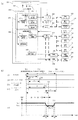
図1(b)は本実施例の制御構成を示すブロック図である。プリンタコントローラ201は、ホストコンピュータ等の外部装置から入力される画像データをプリンタの印刷に必要なビットデータに展開する。制御手段であるエンジン制御部202は、プリンタの各部をプリンタコントローラ201の指示に従って制御するとともに、プリンタコントローラ201へプリンタの内部情報を報知する。エンジン制御部202は、画像間隔調整部210、搬送速度調整部211、連動給紙部212等によって時間を計測するために用いられるシステムタイマ203と、各計算結果を保存するために用いられるメモリ204と、を備えている。また、エンジン制御部202は、画像形成動作を制御するための画像制御部205と、給紙搬送動作を制御するための給紙搬送制御部206と、を備えている。
[Control Configuration of Image Forming Apparatus]
FIG. 1B is a block diagram showing a control configuration of this embodiment. The printer controller 201 expands image data input from an external device such as a host computer into bit data necessary for printer printing. An engine control unit 202 serving as a control unit controls each unit of the printer in accordance with an instruction from the printer controller 201 and notifies the printer controller 201 of internal information about the printer. The engine control unit 202 includes a system timer 203 used for measuring time by the image interval adjustment unit 210, the conveyance speed adjustment unit 211, the interlock paper feeding unit 212, and the like, and a memory 204 used for storing each calculation result. And. The engine control unit 202 includes an image control unit 205 for controlling an image forming operation and a paper feed / conveying control unit 206 for controlling a paper feeding / conveying operation.
画像制御部205は、画像間隔を調整する画像間隔調整部210と、レーザ220を制御するためのレーザ制御部213と、スキャナモータ221を制御するためのスキャナ制御部214と、を備えている。また、画像形成装置101は、転写ローラ122、感光ドラム111、中間転写ベルト130を駆動するためのメインモータ222を備えており、画像制御部205は、メインモータ222を制御するためのメインモータ制御部215を備えている。
The image control unit 205 includes an image interval adjustment unit 210 that adjusts the image interval, a laser control unit 213 that controls the laser 220, and a scanner control unit 214 that controls the scanner motor 221. The image forming apparatus 101 also includes a main motor 222 for driving the transfer roller 122, the photosensitive drum 111, and the intermediate transfer belt 130, and the image control unit 205 controls the main motor 222 for controlling the main motor 222. Part 215.
給紙搬送制御部206は、レジストセンサ162によって用紙を検知したタイミングから用紙の搬送速度を調整するための搬送速度調整部211と、給紙タイミングを決定する連動給紙部212と、を備えている。また、画像形成装置101は、給紙ローラ152、搬送ローラ160、手差しトレイ170用の給紙ローラ171、搬送ローラ180を駆動する駆動手段である給紙モータ224を備えている。給紙搬送制御部206は、給紙モータ224を制御するための給紙モータ制御部216を備えている。また、給紙搬送制御部206は、給紙モータ制御部216により給紙モータ224を駆動している状態のときに給紙ソレノイド225を駆動することにより、給紙カム機構230を動作させる。給紙カム機構230が動作することにより、給紙ローラ152が回転し、給紙トレイ150に積載された用紙Aを給紙することができる。また、給紙搬送制御部206は、給紙モータ制御部216により給紙モータ224を駆動している状態のときに当接手段である給紙ソレノイド226を駆動することにより、給紙カム機構231を動作させる。給紙カム機構231が動作することにより、手差しトレイ170用の給紙ローラ171が回転し、手差しトレイ170に積載された用紙Bを給紙することができる。
The sheet feeding / conveying control unit 206 includes a conveyance speed adjusting unit 211 for adjusting the sheet conveying speed from the timing when the registration sensor 162 detects the sheet, and an interlocked sheet feeding unit 212 for determining the sheet feeding timing. Yes. The image forming apparatus 101 also includes a paper feed roller 152, a transport roller 160, a paper feed roller 171 for the manual feed tray 170, and a paper feed motor 224 that is a driving unit that drives the transport roller 180. The paper feed conveyance control unit 206 includes a paper feed motor control unit 216 for controlling the paper feed motor 224. In addition, the paper feed conveyance control unit 206 operates the paper feed cam mechanism 230 by driving the paper feed solenoid 225 while the paper feed motor control unit 216 is driving the paper feed motor 224. When the paper feed cam mechanism 230 operates, the paper feed roller 152 rotates and the paper A stacked on the paper feed tray 150 can be fed. In addition, the paper feed conveyance control unit 206 drives the paper feed solenoid 226 as a contact means when the paper feed motor 224 is driven by the paper feed motor control unit 216, whereby the paper feed cam mechanism 231. To work. By operating the paper feed cam mechanism 231, the paper feed roller 171 for the manual feed tray 170 rotates and paper B loaded on the manual feed tray 170 can be fed.
[搬送速度調整部]
搬送速度調整部211は、中間転写ベルト130に転写されたトナー画像と用紙の先端を合わせるために、次のような制御を行っている。レジストセンサ162で用紙の先端を検知したタイミングで、搬送速度調整部211は、トナー画像と用紙がそれぞれ転写ローラ122に到達する時間からの時間差を求める。搬送速度調整部211は、用紙が転写ローラ122に到達する前の所定の位置に到達するまでに、トナー画像との時間差を解消するように、用紙を搬送する搬送ローラ180の回転速度を加速又は減速して、用紙を一旦停止させることなく搬送させている。以下、用紙が転写ローラ122に到達する前の所定の位置を、マージポイントという。マージポイントは、用紙にトナー像が転写される転写位置よりも用紙の搬送方向における上流側の所定の位置である。用紙がマージポイントに到達したときに上述した時間差が解消されている場合、用紙が転写ローラ122に到達したときに、トナー画像は転写されるべき用紙の位置に転写されることとなる。このため、以下の説明では、マージポイントまでに時間差が解消されていることを、マージポイントでトナー画像と用紙の先端が合致するという。
[Conveyance speed adjustment section]
The conveyance speed adjustment unit 211 performs the following control in order to align the toner image transferred to the intermediate transfer belt 130 with the leading edge of the paper. At the timing when the leading edge of the paper is detected by the registration sensor 162, the conveyance speed adjustment unit 211 obtains a time difference from the time when the toner image and the paper reach the transfer roller 122, respectively. The conveyance speed adjustment unit 211 accelerates or rotates the rotation speed of the conveyance roller 180 that conveys the sheet so as to eliminate the time difference from the toner image until the sheet reaches a predetermined position before reaching the transfer roller 122. The paper is decelerated and the paper is conveyed without stopping. Hereinafter, a predetermined position before the sheet reaches the transfer roller 122 is referred to as a merge point. The merge point is a predetermined position upstream of the transfer position where the toner image is transferred to the paper in the paper transport direction. When the time difference described above is eliminated when the paper reaches the merge point, when the paper reaches the transfer roller 122, the toner image is transferred to the position of the paper to be transferred. For this reason, in the following description, the fact that the time difference has been eliminated by the merge point means that the toner image matches the leading edge of the paper at the merge point.
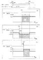
図2は、基本的な搬送速度調整部211の制御について説明する図である。図2の300はエンジン制御部202がプリンタコントローラ201に出力する/TOP信号を示す図で、/TOP信号が出力されたタイミングが、画像形成が開始されるタイミング301である。時間t1については後述する。図2の310は給紙搬送制御部206が給紙ソレノイド226を駆動するために出力する信号を示す図で、信号が出力されたタイミングが、給紙ソレノイドの駆動が開始されるタイミング311である。また、図2(a)から図2(c)までの図において、320はレジストセンサ162から出力される信号を示す。尚、レジストセンサ162が用紙を検知していないときにはローレベル、レジストセンサ162が用紙を検知しているときはハイレベルとしている。300、310、320の横軸はいずれも時間を示す。更に、図2(a)から図2(c)までの図におけるグラフは、横軸に時間、縦軸に用紙の搬送速度(単に、速度と記す)を示す。
FIG. 2 is a diagram for explaining basic control of the conveyance speed adjustment unit 211. 2 is a diagram illustrating a / TOP signal output from the engine control unit 202 to the printer controller 201. The timing at which the / TOP signal is output is a timing 301 at which image formation is started. The time t1 will be described later. 310 in FIG. 2 is a diagram showing a signal output for the paper feed conveyance control unit 206 to drive the paper feed solenoid 226, and the timing at which the signal is output is the timing 311 at which the drive of the paper feed solenoid is started. . 2A to 2C, reference numeral 320 denotes a signal output from the registration sensor 162. FIG. The registration sensor 162 is at a low level when no paper is detected, and is at a high level when the registration sensor 162 is detecting a paper. The horizontal axes of 300, 310, and 320 all indicate time. Further, in the graphs from FIG. 2A to FIG. 2C, the horizontal axis indicates time, and the vertical axis indicates the sheet conveyance speed (simply referred to as speed).
図2(a)は、用紙が理想のタイミング330でレジストセンサ162に到達した場合の図である。理想のタイミングとは、レジストセンサ162に到達した用紙をそのままの速度で搬送すると、マージポイントで中間転写ベルト130上のトナー画像と用紙の先端が合致するタイミングのことをいう。用紙が理想のタイミングでレジストセンサ162に到達した場合、エンジン制御部202は、中間転写ベルト130上のトナー画像がマージポイントに到達するまでに、図2(a)にハッチングで示された面積に相当する距離Lだけ用紙を搬送する。より詳細には、給紙搬送制御部206は、レジストセンサ162により用紙の先端を検知したタイミング(理想のタイミング)330からマージポイントに到達するタイミング302まで用紙を搬送する。ここで、レジストセンサ162により用紙の先端を検知したタイミングからマージポイントに用紙の先端が到達したタイミング302までの時間をT0、この間の用紙の搬送速度を所定の速度であるVpreとしている。
これは、用紙がレジストセンサ162に到達してから、中間転写ベルト130上のトナー画像がマージポイントに到達するまでに、用紙を距離Lだけ搬送することによって、用紙上の所定の位置にトナー画像を転写することができることを意味する。
FIG. 2A is a diagram when the sheet reaches the registration sensor 162 at an ideal timing 330. The ideal timing is the timing at which the toner image on the intermediate transfer belt 130 and the leading edge of the paper coincide at the merge point when the paper that has reached the registration sensor 162 is conveyed at the same speed. When the sheet reaches the registration sensor 162 at an ideal timing, the engine control unit 202 sets the area indicated by hatching in FIG. 2A until the toner image on the intermediate transfer belt 130 reaches the merge point. The paper is conveyed by a corresponding distance L. More specifically, the paper feed conveyance control unit 206 conveys the paper from timing (ideal timing) 330 when the registration sensor 162 detects the leading edge of the paper to timing 302 when the merge point is reached. Here, the time from the timing when the leading edge of the sheet is detected by the registration sensor 162 to the timing 302 when the leading edge of the sheet reaches the merge point is T0, and the sheet conveyance speed during this period is Vpre which is a predetermined speed.
This is because the toner image is moved to a predetermined position on the paper by transporting the paper by the distance L after the paper reaches the registration sensor 162 and before the toner image on the intermediate transfer belt 130 reaches the merge point. Can be transferred.
図2(b)は、理想のタイミング330よりも早く用紙がレジストセンサ162に到達した場合の図である。図2(b)では、理想のタイミング330よりも時間T0d早いタイミング332で、レジストセンサ162が用紙の先端を検知している。上述したように、マージポイントで中間転写ベルト130上のトナー画像と用紙の先端をあわせるには、マージポイントまでに、図2(a)同様、距離Lだけ用紙を搬送する必要がある。しかし、図2(b)のケースは、図2(a)のケースよりも用紙を搬送する時間が時間T0dの分長くなるため、時間T0dの間に搬送されてしまう距離に相当する分、用紙の搬送速度を遅くして、用紙が搬送される距離を図2(a)の距離Lと同じにすればよい。ここで、図2(a)の場合の用紙の搬送速度Vpreよりも遅くした搬送速度をVdownとする。また、レジストセンサ162により用紙の先端を検知してから用紙がマージポイントまで搬送速度Vdownで搬送される距離をLdとする。距離Ldは図2(b)にハッチングで示される面積に相当する。上述したように、距離Lと距離Ldが等しくなるような搬送速度Vdownとすればよい。
FIG. 2B is a diagram when the paper reaches the registration sensor 162 earlier than the ideal timing 330. In FIG. 2B, the registration sensor 162 detects the leading edge of the sheet at a timing 332 that is earlier than the ideal timing 330 by a time T0d. As described above, in order to align the toner image on the intermediate transfer belt 130 with the leading edge of the sheet at the merge point, it is necessary to transport the sheet by the distance L as in FIG. However, in the case of FIG. 2B, the time for transporting the paper is longer by the time T0d than in the case of FIG. 2A, and therefore the paper is equivalent to the distance that is transported during the time T0d. And the distance that the sheet is conveyed may be the same as the distance L in FIG. Here, a conveyance speed that is slower than the sheet conveyance speed Vpre in the case of FIG. Further, the distance at which the sheet is conveyed at the conveyance speed Vdown from the detection of the leading edge of the sheet by the registration sensor 162 to the merge point is Ld. The distance Ld corresponds to the area indicated by hatching in FIG. As described above, the conveyance speed Vdown may be set such that the distance L and the distance Ld are equal.
図2(c)は、図2(b)とは反対に、理想のタイミング330よりも遅く用紙がレジストセンサ162に到達した場合の図である。図2(c)では、理想のタイミング330よりも時間T0u遅いタイミング334で、レジストセンサ162が用紙の先端を検知している。この場合、マージポイントで中間転写ベルト130上のトナー画像と用紙の先端をあわせるには、マージポイントまでに、図2(a)同様、距離Lだけ用紙を搬送する必要がある。しかし、図2(c)のケースは、図2(a)のケースよりも用紙を搬送する時間が時間T0uの分短くなるため、時間T0uの間に搬送できない距離に相当する分、用紙の搬送速度を速くして、用紙が搬送される距離を図2(a)の距離Lと同じにすればよい。ここで、図2(a)の場合の用紙の搬送速度Vpreよりも早くした搬送速度をVupとする。また、レジストセンサ162により用紙の先端を検知してから用紙がマージポイントまで搬送速度Vupで搬送される距離をLuとする。距離Luは図2(c)にハッチングで示される面積に相当する。上述したように、距離Lと距離Luが等しくなるような搬送速度Vupとすればよい。
FIG. 2C is a diagram when the sheet reaches the registration sensor 162 later than the ideal timing 330, contrary to FIG. 2B. In FIG. 2C, the registration sensor 162 detects the leading edge of the sheet at a timing 334 later than the ideal timing 330 by a time T0u. In this case, in order to align the toner image on the intermediate transfer belt 130 with the leading edge of the paper at the merge point, it is necessary to transport the paper by the distance L until the merge point, as in FIG. However, in the case of FIG. 2C, the time for transporting the paper is shorter by the time T0u than in the case of FIG. 2A, so that the paper is transported by an amount corresponding to the distance that cannot be transported during the time T0u. It is only necessary to increase the speed so that the distance that the sheet is conveyed is the same as the distance L in FIG. Here, a transport speed that is faster than the paper transport speed Vpre in the case of FIG. Further, the distance at which the sheet is conveyed at the conveyance speed Vup from the detection of the leading edge of the sheet by the registration sensor 162 to the merge point is defined as Lu. The distance Lu corresponds to the area indicated by hatching in FIG. As described above, the conveyance speed Vup may be set so that the distance L and the distance Lu are equal.
[本実施例の搬送速度制御]
図3は、本実施例の搬送速度調整部211の制御を詳細に説明する図である。図3(a)は、レジストセンサ162に用紙の先端が到達したタイミング431が、理想のタイミング421より早い場合の図である。図3(b)は、レジストセンサ162に用紙の先端が到達したタイミング432が、理想のタイミング421より遅い場合の図である。また、各図の(i)はエンジン制御部202からプリンタコントローラ201に出力される/TOP信号を示し、タイミング401は画像形成が開始されたタイミングを示す。各図の(ii)は、給紙搬送制御部206から給紙ソレノイド226に出力される信号を示し、タイミング411は給紙ソレノイド226が駆動され、給紙が開始されるタイミングを示す。各図の(iii)は、用紙の搬送が理想的に行われている場合のレジストセンサ162から出力される信号を示し、タイミング421は給紙された用紙が搬送のばらつきなくレジストセンサ162に到達した理想のタイミング(理論値)を示す。理想のタイミング421で用紙の先端がレジストセンサ162に到達した場合、レジストセンサ162の位置から下流側の搬送路上では用紙の搬送速度を変更する必要がなく、用紙の先端を画像の先端に合わせることができる。各図の(iv)は、レジストセンサ162から出力される信号を示し、タイミング431及びタイミング432は、実際に搬送されている用紙の先端がレジストセンサ162によって検知されたタイミング(実測)を示している。また、タイミング402は、中間転写ベルト130上に形成された画像の先端がマージポイントに到達したタイミングを示す。いずれも横軸は時間を示す。更に、各図の(v)は、横軸に時間、縦軸に用紙の搬送速度を示す。
[Conveyance speed control of this embodiment]
FIG. 3 is a diagram illustrating in detail the control of the conveyance speed adjustment unit 211 of the present embodiment. FIG. 3A is a diagram when the timing 431 at which the leading edge of the sheet reaches the registration sensor 162 is earlier than the ideal timing 421. FIG. 3B is a diagram when the timing 432 at which the leading edge of the sheet reaches the registration sensor 162 is later than the ideal timing 421. Further, (i) in each figure shows a / TOP signal output from the engine control unit 202 to the printer controller 201, and a timing 401 shows a timing at which image formation is started. (Ii) in each figure shows a signal output from the paper feed conveyance control unit 206 to the paper feed solenoid 226, and timing 411 shows a timing at which the paper feed solenoid 226 is driven and paper feed is started. (Iii) in each figure shows a signal output from the registration sensor 162 when the paper is transported ideally, and a timing 421 indicates that the fed paper reaches the registration sensor 162 without variations in transport. Shows the ideal timing (theoretical value). When the leading edge of the sheet reaches the registration sensor 162 at the ideal timing 421, it is not necessary to change the sheet conveyance speed on the conveyance path downstream from the position of the registration sensor 162, and the leading edge of the sheet is aligned with the leading edge of the image. Can do. (Iv) in each figure indicates a signal output from the registration sensor 162, and timings 431 and 432 indicate timing (actual measurement) at which the leading edge of the actually conveyed paper is detected by the registration sensor 162. Yes. A timing 402 indicates a timing at which the leading edge of the image formed on the intermediate transfer belt 130 reaches the merge point. In either case, the horizontal axis represents time. Furthermore, (v) of each figure shows time on the horizontal axis and the paper conveyance speed on the vertical axis.
(理想のタイミングより早い場合)
図3(a)を用いて、レジストセンサ162に用紙の先端が到達したタイミング431が、理想のタイミング421より早い場合の制御について説明する。/TOP信号が出力されたタイミング401から、トナー画像の先端(以下、画像先端という)がマージポイントに到達するタイミング402までの時間をt1とする。レジストセンサ162に用紙の先端が到達したタイミング431から、画像先端がマージポイントに到達するタイミング402までにシステムタイマ203によって計測された時間に基づき求められる実測時間をt2とする。/TOP信号が出力されたタイミング401から、理想のタイミング421までの時間をt3とする。
(If it is earlier than the ideal timing)
The control when the timing 431 when the leading edge of the paper reaches the registration sensor 162 is earlier than the ideal timing 421 will be described with reference to FIG. The time from the timing 401 when the / TOP signal is output to the timing 402 when the leading edge of the toner image (hereinafter referred to as the leading edge of the image) reaches the merge point is defined as t1. Let t2 be an actual measurement time obtained based on the time measured by the system timer 203 from the timing 431 when the leading edge of the paper reaches the registration sensor 162 to the timing 402 when the leading edge of the image reaches the merge point. The time from the timing 401 at which the / TOP signal is output to the ideal timing 421 is defined as t3.
時間t1、t3は、ばらつきを受けない所定の決まった値であるため、エンジン制御部202のメモリ204に予め保持しておく。また、給紙搬送制御部206は、タイミング431でレジストセンサ162により用紙の先端を検知することで時間t2を確定して、用紙がレジストセンサ162に到達する時間的な誤差Δtを、以下の式(1)から算出する。ここで、給紙搬送制御部206は、/TOP信号が出力されたタイミング401にシステムタイマ203による時間の計測を開始しておく。給紙搬送制御部206は、用紙の先端をレジストセンサ162により検知したタイミングでシステムタイマ203を参照することにより、時間t1から計測した時間を減じて時間t2を求める。
用紙は、レジストセンサ162の位置への先端の到達が時間Δt早まることによって、以下の式(2)に示すように、距離U1だけの進みが発生する。
Since the times t1 and t3 are predetermined values that are not subject to variations, they are stored in the memory 204 of the engine control unit 202 in advance. In addition, the paper feed conveyance control unit 206 determines the time t2 by detecting the leading edge of the paper with the registration sensor 162 at the timing 431, and calculates the time error Δt when the paper reaches the registration sensor 162 by the following equation. Calculate from (1). Here, the paper feed conveyance control unit 206 starts measuring the time by the system timer 203 at the timing 401 when the / TOP signal is output. The paper feed conveyance control unit 206 obtains the time t2 by subtracting the measured time from the time t1 by referring to the system timer 203 at the timing when the leading edge of the paper is detected by the registration sensor 162.
When the leading edge of the sheet reaches the position of the registration sensor 162 is advanced by time Δt, the sheet advances by the distance U1 as shown in the following equation (2).
したがって、所定のタイミングまでに用紙をマージポイントへ搬送するためには、用紙の搬送速度を遅くし、トナー画像がマージポイントに到達するタイミング402までに、距離U1に相当する分遅らせる必要がある。ここで、用紙がレジストセンサ162に早く到達したために進んだ距離U1を遅らせるために必要な搬送速度をVdown、搬送速度Vdownで用紙を搬送する時間(以下、搬送時間という)をTdownとする。また、用紙の搬送速度をVpreからVdownに遅くするための時間(以下、立ち下げ時間という)をTa、用紙の搬送速度をVdownからVpreに速くするための時間(以下、立ち上げ時間という)をTbとする。そうすると、搬送速度をVpreからVdownに遅くすることによって、遅らせることができる距離U2は、以下の式(3)によって求められる。
Therefore, in order to transport the paper to the merge point by a predetermined timing, it is necessary to slow down the paper transport speed and delay it by an amount corresponding to the distance U1 until the timing 402 when the toner image reaches the merge point. Here, it is assumed that the conveyance speed necessary for delaying the distance U1 traveled because the sheet arrived at the registration sensor 162 early is Vdown, and the time for conveying the sheet at the conveyance speed Vdown (hereinafter referred to as conveyance time) is Tdown. In addition, a time for slowing the sheet conveyance speed from Vpre to Vdown (hereinafter referred to as a fall time) is Ta, and a time for increasing the sheet conveyance speed from Vdown to Vpre (hereinafter referred to as a rise time). Let Tb. Then, the distance U2 that can be delayed by reducing the transport speed from Vpre to Vdown is obtained by the following equation (3).
以上より、距離U1と距離U2が等しくなるように(U1=U2)、搬送速度Vdown、搬送時間Tdown、立ち下げ時間Ta、立ち上げ時間Tbを決定する必要がある。
U1=U2より、以下の式(4)のように表せる。
From the above, it is necessary to determine the conveyance speed Vdown, the conveyance time Tdown, the falling time Ta, and the rising time Tb so that the distance U1 is equal to the distance U2 (U1 = U2).
From U1 = U2, it can be expressed as the following formula (4).
また、搬送速度調整部211は、画像先端がマージポイントに到達するタイミング402までの時間t2が経過するまでに、用紙の搬送速度をVdownからVpreに戻す必要がある。このため、以下の式(5)を満たす必要がある。
式(4)、式(5)より、以下の式(6)が導かれる。
Further, the conveyance speed adjustment unit 211 needs to return the conveyance speed of the sheet from Vdown to Vpre before the time t2 until the timing 402 at which the leading edge of the image reaches the merge point has elapsed. For this reason, it is necessary to satisfy the following formula (5).
From the equations (4) and (5), the following equation (6) is derived.
立ち下げ時間Ta、立ち上げ時間Tbは、給紙モータ224の加速度をαとすると、以下の式(7)で表される。尚、給紙モータ224の加速度αの値は、予めメモリ204に記憶されているものとする。
したがって、式(6)、式(7)より、以下の式(8)が導かれる。
The fall time Ta and the rise time Tb are expressed by the following formula (7), where the acceleration of the paper feed motor 224 is α. Note that the value of the acceleration α of the paper feed motor 224 is stored in the memory 204 in advance.
Therefore, the following equation (8) is derived from the equations (6) and (7).
よって、式(8)を変形して以下の式(9)が導かれる。
式(9)を解いて、搬送速度Vdownについて、以下の式(10)が導かれる。
したがって、搬送速度Vdownが式(10)で示される範囲内にあれば、用紙の搬送速度について加速又は減速(以下、加減速)の制御を実施することが可能となる。
Therefore, the following equation (9) is derived by modifying the equation (8).
By solving the equation (9), the following equation (10) is derived for the conveyance speed Vdown.
Therefore, if the conveyance speed Vdown is within the range expressed by the equation (10), it is possible to control acceleration or deceleration (hereinafter referred to as acceleration / deceleration) for the conveyance speed of the paper.
ここでは、用紙の搬送速度を決定する際の一例として、式(10)の範囲における中心値を搬送速度Vdownとする。即ち、搬送速度Vdownは以下の式(11)で表される。
また、用紙を搬送速度Vdownの搬送時間Tdownは、式(4)、式(7)より、以下の式(12)により決定される。
式(11)、式(12)より、搬送速度調整部211は、用紙の先端がレジストセンサ162に到達してから搬送速度をVpreからVdownに減速し、時間Tdownが経過するまで搬送速度Vdownで用紙を搬送する。そして、搬送速度調整部211は、時間Tdownが経過した後に搬送速度をVdownからVpreに戻す。
Here, as an example when determining the sheet conveyance speed, the center value in the range of Expression (10) is defined as the conveyance speed Vdown. That is, the conveyance speed Vdown is expressed by the following equation (11).
Further, the conveyance time Tdown of the sheet conveyance speed Vdown is determined by the following equation (12) from the equations (4) and (7).
From Expressions (11) and (12), the conveyance speed adjustment unit 211 reduces the conveyance speed from Vpre to Vdown after the leading edge of the sheet reaches the registration sensor 162, and continues at the conveyance speed Vdown until time Tdown elapses. Transport the paper. Then, the transport speed adjusting unit 211 returns the transport speed from Vdown to Vpre after the time Tdown has elapsed.
(理想のタイミングより遅い場合)
図3(b)を用いて、レジストセンサ162に用紙の先端が到達したタイミング432が、理想のタイミング421より遅い場合の制御について説明する。/TOP信号が出力されたタイミング401から、画像先端がマージポイントに到達するタイミング402までの時間をt1とする。レジストセンサ162に用紙の先端が到達したタイミング432から、画像先端がマージポイントに到達するタイミング402までにシステムタイマ203によって計測された時間に基づき求められる実測時間をt2’とする。/TOP信号が出力されたタイミング401から、理想のタイミング421までの時間をt3とする。
(If it is later than the ideal timing)
The control when the timing 432 when the leading edge of the sheet reaches the registration sensor 162 is later than the ideal timing 421 will be described with reference to FIG. The time from the timing 401 at which the / TOP signal is output to the timing 402 at which the leading edge of the image reaches the merge point is defined as t1. An actual measurement time obtained based on the time measured by the system timer 203 from the timing 432 when the leading edge of the sheet reaches the registration sensor 162 to the timing 402 when the leading edge of the image reaches the merge point is defined as t2 ′. The time from the timing 401 at which the / TOP signal is output to the ideal timing 421 is defined as t3.
時間t1、t3は、上述したようにばらつきを受けない所定の決まった値であるため、エンジン制御部202のメモリ204に予め保持しておく。また、給紙搬送制御部206は、タイミング432でレジストセンサ162により用紙の先端を検知することで時間t2’を確定して、用紙がレジストセンサ162に到達する時間的な誤差Δt’を、以下の式(13)から算出する。
用紙は、レジストセンサ162の位置への先端の到達が時間Δt’遅れることによって、以下の式(14)に示すように、距離U3だけの遅れが発生する。
Since the times t1 and t3 are predetermined values that are not subject to variations as described above, they are stored in the memory 204 of the engine control unit 202 in advance. Further, the paper feed conveyance control unit 206 determines the time t2 ′ by detecting the leading edge of the paper with the registration sensor 162 at the timing 432, and sets a time error Δt ′ for the paper to reach the registration sensor 162 as follows. (13).
When the leading edge of the sheet reaches the position of the registration sensor 162 is delayed by a time Δt ′, a delay of a distance U3 occurs as shown in the following equation (14).
したがって、所定のタイミングまでに用紙をマージポイントへ搬送するには、用紙の搬送速度を速くし、画像がマージポイントに到達するタイミング402までに、距離U3に相当する分進める必要がある。ここで、用紙がレジストセンサ162に遅れて到達したために遅れた距離U3を取り戻すために必要な搬送速度をVup、搬送速度Vupで用紙を搬送する搬送時間をTupとする。また、用紙の搬送速度をVpreからVupに速くするための立ち上げ時間をTc、用紙の搬送速度をVupからVpreに遅くするための立ち下げ時間をTdとする。そうすると、搬送速度をVpreからVupに速くすることによって取り戻すことができる距離U4は、以下の式(15)によって求められる。
Therefore, in order to convey the sheet to the merge point by a predetermined timing, it is necessary to increase the sheet conveyance speed and advance by an amount corresponding to the distance U3 until the timing 402 when the image reaches the merge point. Here, it is assumed that the transport speed necessary to recover the distance U3 that is delayed because the paper arrives late at the registration sensor 162 is Vup, and the transport time for transporting the paper at the transport speed Vup is Tup. Also, let Tc be the rise time for increasing the paper transport speed from Vpre to Vup, and Td be the fall time for slowing the paper transport speed from Vup to Vpre. Then, the distance U4 that can be recovered by increasing the transport speed from Vpre to Vup is obtained by the following equation (15).
以上より、距離U3と距離U4が等しくなるように(U3=U4)、搬送速度Vup、搬送時間Tup、立ち上げ時間Tc、立ち下げ時間Tdを決定する必要がある。U3=U4より、以下の式(16)のように表せる。
From the above, it is necessary to determine the conveyance speed Vup, the conveyance time Tup, the rise time Tc, and the fall time Td so that the distance U3 and the distance U4 are equal (U3 = U4). From U3 = U4, it can be expressed as the following equation (16).
また、搬送速度調整部211は、画像先端がマージポイントに到達するタイミング402までの時間t2’が経過するまでに、用紙の搬送速度をVupからVpreに戻す必要がある。このため、以下の式(17)を満たす必要がある。
式(16)、式(17)より、以下の式(18)が導かれる。
Further, the transport speed adjusting unit 211 needs to return the transport speed of the sheet from Vup to Vpre before the time t2 ′ until the timing 402 at which the leading edge of the image reaches the merge point has elapsed. For this reason, it is necessary to satisfy the following expression (17).
From the equations (16) and (17), the following equation (18) is derived.
立ち上げ時間Tc、立ち下げ時間Tdは、給紙モータ224の加速度を上述したようにαとすると、以下の式(19)で表される。
したがって、式(18)、式(19)より、以下の式(20)が導かれる。
よって、式(20)を変形して以下の式(21)が導かれる。
式(21)を解いて、搬送速度Vupについて、以下の式(22)が導かれる。
したがって、搬送速度Vupが式(22)で示される範囲内にあれば、用紙の搬送速度について加減速の制御を実施することが可能となる。
The rise time Tc and the fall time Td are expressed by the following equation (19), where α is the acceleration of the paper feed motor 224 as described above.
Therefore, the following equation (20) is derived from the equations (18) and (19).
Therefore, the following equation (21) is derived by modifying the equation (20).
Equation (21) is solved, and the following equation (22) is derived for the conveyance speed Vup.
Therefore, if the transport speed Vup is within the range expressed by the equation (22), it is possible to control acceleration / deceleration for the transport speed of the paper.
ここでは、用紙の搬送速度を決定する際の一例として、式(22)の範囲における中心値を搬送速度Vupとする。即ち、搬送速度Vupは以下の式(23)のようになる。
また、搬送速度Vupの搬送時間Tupは、式(16)、式(19)より、以下の式(24)により決定される。
式(23)、式(24)より、搬送速度調整部211は、用紙の先端がレジストセンサ162に到達してから搬送速度をVpreからVupに加速し、搬送時間Tupが経過するまで搬送速度Vupで用紙を搬送する。そして、搬送速度調整部211は、搬送時間Tupが経過した後に搬送速度をVupからVpreに戻す。
Here, as an example of determining the sheet conveyance speed, the center value in the range of Expression (22) is defined as the conveyance speed Vup. That is, the conveyance speed Vup is expressed by the following equation (23).
Further, the transport time Tup of the transport speed Vup is determined by the following equation (24) from the equations (16) and (19).
From Expressions (23) and (24), the conveyance speed adjusting unit 211 accelerates the conveyance speed from Vpre to Vup after the leading edge of the sheet reaches the registration sensor 162, and the conveyance speed Vup until the conveyance time Tup elapses. Transport the paper. Then, the transport speed adjusting unit 211 returns the transport speed from Vup to Vpre after the transport time Tup has elapsed.
以上より、搬送速度調整部211は、/TOP信号が出力されたタイミング401と、レジストセンサ162に用紙の先端が到達する理想のタイミング421と実際に到達したタイミング431、432に基づき、搬送制御を行う。即ち、搬送速度調整部211は、マージポイントにおいて用紙の先端と画像の先端を合わせる制御を行っている。
As described above, the transport speed adjustment unit 211 performs transport control based on the timing 401 at which the / TOP signal is output, the ideal timing 421 at which the leading edge of the paper reaches the registration sensor 162, and the actual timings 431 and 432. Do. In other words, the conveyance speed adjustment unit 211 performs control to align the leading edge of the sheet and the leading edge of the image at the merge point.
[手差し給紙構成]
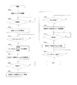
本実施例では、手差しトレイ170に積載された用紙を給紙する際の制御を示す。図4は手差しトレイ170において給紙動作と稼働音の関係を示した図である。図4(a)は、手差しトレイ170近傍の要部のみを示す図であり、手差しトレイ170上に載置された用紙Bを給紙する際に、給紙ソレノイド226を駆動したタイミング(図3のタイミング411)の状態を示す。図4(b)は、同様に手差しトレイ170近傍の要部のみを示す図であり、給紙ソレノイド226の駆動を開始した後、用紙Bと給紙ローラ171が当接したタイミングの状態を示す。
[Manual feed configuration]
In the present embodiment, control when feeding sheets stacked on the manual feed tray 170 is shown. FIG. 4 is a diagram showing the relationship between the sheet feeding operation and the operating sound in the manual feed tray 170. FIG. 4A is a diagram showing only the main part in the vicinity of the manual feed tray 170, and when the paper B placed on the manual feed tray 170 is fed, the timing at which the paper feed solenoid 226 is driven (FIG. 3). The timing 411) of FIG. FIG. 4B is a diagram similarly showing only the main part in the vicinity of the manual feed tray 170, and shows the state of timing when the paper B and the paper feed roller 171 come into contact after the drive of the paper feed solenoid 226 is started. .
不図示のカムやバネ等からなる給紙カム機構231が動作してから、昇降板172が上昇し、用紙Bが昇降板172によって押し上げられる。これにより、用紙Bが給紙ローラ171に当接する。用紙Bが給紙ローラ171に当接するタイミングは、給紙モータ224の回転量によってメカニカルに決まる。ただし、用紙Bの積載量や、給紙ソレノイド226の応答時間等により、用紙Bが給紙ローラ171に当接するまでの時間は変化する。具体的には、積載されている用紙Bの量が多い方が用紙Bは給紙ローラ171に早く当接し、給紙ソレノイド226の応答時間が早い方が用紙Bは給紙ローラ171に早く当接する。
After the sheet feeding cam mechanism 231 including a cam and a spring (not shown) is operated, the elevating plate 172 is raised and the paper B is pushed up by the elevating plate 172. As a result, the paper B comes into contact with the paper feed roller 171. The timing at which the paper B contacts the paper feed roller 171 is mechanically determined by the amount of rotation of the paper feed motor 224. However, the time until the sheet B comes into contact with the sheet feeding roller 171 varies depending on the loading amount of the sheet B, the response time of the sheet feeding solenoid 226, and the like. Specifically, the larger the amount of loaded paper B, the faster the paper B contacts the paper feed roller 171, and the faster the response time of the paper feed solenoid 226, the faster paper B hits the paper feed roller 171. Touch.
図4(c)は給紙モータ224を速度Vpreで動作するように駆動させ、手差しトレイ170の用紙Bを給紙する際の稼働音を示した図であり、横軸を時間[sec]、縦軸を稼働音[dB]としている。また、図4(c)中では、図4(a)のタイミングを(a)、図4(b)のタイミングを(b)としている。図4(a)のタイミングで給紙ソレノイド226が駆動された後、図4(b)のタイミングで給紙ローラ171に用紙Bが当接する際に稼働音が最大となる。このときの稼働音は、用紙Bが給紙ローラ171に当接する際の衝突音である。
FIG. 4C is a diagram showing the operation sound when the paper feed motor 224 is driven to operate at the speed Vpre and the paper B on the manual feed tray 170 is fed. The horizontal axis represents time [sec], The vertical axis represents operating sound [dB]. In FIG. 4C, the timing of FIG. 4A is (a), and the timing of FIG. 4B is (b). After the sheet feeding solenoid 226 is driven at the timing of FIG. 4A, the operating noise becomes maximum when the sheet B comes into contact with the sheet feeding roller 171 at the timing of FIG. The operating sound at this time is a collision sound when the paper B comes into contact with the paper feed roller 171.
上述したように、用紙Bが給紙ローラ171に当接するタイミングは、手差しトレイ170に積載されている用紙Bの量や、給紙ソレノイド226の応答時間によって変わる。そこで、用紙Bが給紙ローラ171に当接するタイミングの中で最も早いタイミングと最も遅いタイミングを、給紙ソレノイド226を駆動してから昇降板172が給紙ローラ171に当接するまでの、給紙モータ224よって用紙Bが移動される距離に換算する。ここで、用紙Bが給紙ローラ171に当接するタイミングの中で最も早いタイミングとなるときに換算された用紙Bが移動される距離を最短移動距離L1、最も遅いタイミングとなるときに換算された用紙Bが移動される距離を最長移動距離L2とする。そうすると、給紙モータ224は速度Vpreで動作しているため、最も早いタイミングはL1/Vpreで表され、最も遅いタイミングはL2/Vpreで表される。
As described above, the timing at which the paper B comes into contact with the paper feed roller 171 varies depending on the amount of the paper B stacked on the manual feed tray 170 and the response time of the paper feed solenoid 226. Therefore, the earliest timing and the latest timing among the timings at which the sheet B comes into contact with the sheet feeding roller 171 are the time from when the sheet feeding solenoid 226 is driven to when the lifting plate 172 contacts the sheet feeding roller 171. This is converted into the distance that the paper B is moved by the motor 224. Here, the distance traveled by the paper B when the paper B comes into contact with the paper feed roller 171 is the earliest timing, and the distance traveled by the shortest movement distance L1 is converted when the paper B is moved at the latest timing. The distance that the paper B is moved is the longest movement distance L2. Then, since the paper feed motor 224 operates at the speed Vpre, the earliest timing is represented by L1 / Vpre, and the latest timing is represented by L2 / Vpre.
従来は、給紙モータ224を減速させることで、用紙を給紙する際の衝突音を低減させていた。しかし、搬送路上で先行する用紙が搬送されているときに給紙モータ224を減速させた場合、給紙モータ224により駆動されている搬送ローラ160の回転速度も減速させてしまう。このため、一のモータで、用紙の積載部から用紙を給紙するためのソレノイドと転写部へ用紙を搬送するためのローラとを駆動する構成の画像形成装置では、用紙に対して画像を正しく転写させることができない。例えば、上述したように、給紙モータ224で給紙ソレノイド226と搬送ローラ160を駆動している場合には、給紙モータ224を減速させると搬送ローラ160も減速されてしまう。そこで、本実施例では、図3(a)のように搬送速度調整部211により、給紙モータ224を減速する制御を実施しているときに、後続の用紙Bの給紙を行う構成とする。このような構成とすることで、最長移動距離L2となる範囲内において、用紙Bが給紙ローラ171に当接する際に発生する衝突音を低減させる。
Conventionally, by decelerating the paper feed motor 224, the collision noise when paper is fed has been reduced. However, when the paper feed motor 224 is decelerated while the preceding paper is being conveyed on the conveyance path, the rotational speed of the conveyance roller 160 driven by the paper feed motor 224 is also decelerated. For this reason, in an image forming apparatus configured to drive a solenoid for feeding paper from the paper stacking unit and a roller for conveying the paper to the transfer unit with one motor, the image is correctly displayed on the paper. Cannot be transferred. For example, as described above, when the paper feed motor 224 drives the paper feed solenoid 226 and the transport roller 160, if the paper feed motor 224 is decelerated, the transport roller 160 is also decelerated. Therefore, in the present embodiment, as illustrated in FIG. 3A, when the conveyance speed adjustment unit 211 performs control to decelerate the paper feed motor 224, the subsequent paper B is fed. . With such a configuration, the collision noise generated when the paper B comes into contact with the paper feed roller 171 within the range of the longest movement distance L2 is reduced.
[画像間隔調整部]
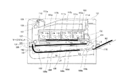
図5は、本実施例の搬送速度調整部211により給紙モータ224の速度を減速する際の中間転写ベルト130上のトナー画像と用紙の位置関係を説明する図である。尚、図5では説明上必要のない部材を省略している。レジストセンサ162とマージポイント間の搬送路に沿った距離を第一の区間であるL3とする。本実施例ではL3は、給紙ソレノイド226を駆動してから用紙Bが給紙ローラ171に当接するまでの最も遅いタイミングを距離に換算した最長移動距離L2よりも長い構成とする。
[Image interval adjuster]
FIG. 5 is a diagram illustrating the positional relationship between the toner image on the intermediate transfer belt 130 and the paper when the speed of the paper feed motor 224 is reduced by the transport speed adjustment unit 211 of the present embodiment. In FIG. 5, members not necessary for explanation are omitted. The distance along the conveyance path between the registration sensor 162 and the merge point is defined as L3 which is the first section. In this embodiment, L3 is configured to be longer than the longest moving distance L2 in which the latest timing from when the paper feed solenoid 226 is driven until the paper B comes into contact with the paper feed roller 171 is converted into a distance.
用紙B1がレジストセンサ162に到達してから、用紙B1と用紙B1に転写される第一のトナー画像C1の先端を合わせるためのマージポイントに到達するまでに、給紙モータ224を減速することができる。給紙モータ224を減速している間、並行して用紙B1に続いて搬送される後続の用紙(以下、後続紙という)B2の給紙を行うため、給紙搬送制御部206は給紙ソレノイド226を駆動する。尚、用紙B1は、後続紙B2に対しては先行して搬送されている用紙であるため、先行紙B1ともいう。
The sheet feeding motor 224 may be decelerated after the sheet B1 reaches the registration sensor 162 and before reaching the merge point for aligning the leading edge of the first toner image C1 transferred to the sheet B1 and the sheet B1. it can. While the sheet feeding motor 224 is decelerated, the sheet feeding / conveying control unit 206 feeds a succeeding sheet (hereinafter referred to as a succeeding sheet) B2 that is conveyed following the sheet B1 in parallel. 226 is driven. Note that the sheet B1 is also referred to as a preceding sheet B1 because it is a sheet that is conveyed in advance of the succeeding sheet B2.
ここで、図3(a)のように給紙モータ224を減速させるためには、中間転写ベルト130上のトナー画像C1よりも早く用紙B1がレジストセンサ162に到達している必要がある。そのため、給紙ローラ171からレジストセンサ162までの搬送路に沿った距離をL4とすると、画像形成の間隔L5は、次の式(25)で表される。ここで、画像形成の間隔L5は、先行紙B1に転写されるトナー画像C1の先端から、後続紙B2に転写される第二のトナー画像C2の先端までの中間転写ベルト130に沿った距離をいう。
L5=L4+給紙搬送遅れ設定値・・・(25)
Here, in order to decelerate the paper feed motor 224 as shown in FIG. 3A, the paper B1 needs to reach the registration sensor 162 earlier than the toner image C1 on the intermediate transfer belt 130. Therefore, if the distance along the conveyance path from the paper feed roller 171 to the registration sensor 162 is L4, the image formation interval L5 is expressed by the following equation (25). Here, the image formation interval L5 is a distance along the intermediate transfer belt 130 from the leading edge of the toner image C1 transferred to the preceding paper B1 to the leading edge of the second toner image C2 transferred to the succeeding paper B2. Say.
L5 = L4 + feeding conveyance delay setting value (25)
画像形成の間隔L5に相当する時間(以下、画像形成の間隔時間という)t4は、以下の式(26)で表される。
A time t4 (hereinafter referred to as an image formation interval time) t4 corresponding to the image formation interval L5 is expressed by the following equation (26).
ここで、給紙搬送遅れ設定値とは、給紙ローラ171や搬送ローラ180の摩耗や、個体ばらつき、給紙ソレノイド226の応答時間等、用紙の搬送が遅れる要因を距離に換算して加算した値である。給紙搬送遅れ設定値は、予めメモリ204に記憶されている。給紙搬送遅れ設定値を距離L4に加算することで、給紙ローラ171や搬送ローラ180が摩耗したとしても、図3(a)のようにトナー画像よりも先に用紙がレジストセンサ162に到達する。また、本実施例は、先行紙B1がレジストセンサ162に到達し、給紙モータ224を減速している際に後続紙B2を給紙する。このため、給紙ローラ171からレジストセンサ162までの距離L4よりも用紙長が短い用紙に対して実施される。ここで、用紙長とは、用紙の搬送方向の長さのことである。画像間隔調整部210は、メモリ204から給紙搬送遅れ設定値を読み出し、式(25)、式(26)を用いて時間t4を算出し、エンジン制御部202は、時間t4に基づき/TOP信号を出力する。
Here, the paper feed conveyance delay setting value is obtained by converting a factor of paper conveyance delay such as wear of the paper feed roller 171 and the transport roller 180, individual variation, response time of the paper feed solenoid 226, and the like into a distance. Value. The paper feed conveyance delay setting value is stored in the memory 204 in advance. By adding the paper feed conveyance delay setting value to the distance L4, even if the paper feed roller 171 and the transport roller 180 are worn, the paper reaches the registration sensor 162 before the toner image as shown in FIG. To do. In the present embodiment, when the preceding paper B1 reaches the registration sensor 162 and the paper feeding motor 224 is decelerated, the succeeding paper B2 is fed. For this reason, it is performed on a sheet having a sheet length shorter than the distance L4 from the sheet feeding roller 171 to the registration sensor 162. Here, the paper length is the length in the paper transport direction. The image interval adjustment unit 210 reads the paper feed conveyance delay setting value from the memory 204, calculates the time t4 using the equations (25) and (26), and the engine control unit 202 performs the / TOP signal based on the time t4. Is output.
[タイミングチャート]
図6は、本実施例の搬送速度調整部211及び連動給紙部212の制御を示すタイミングチャートである。図6(i)〜図6(v)は、図3(a)の(i)〜(v)に対応しており、図3(a)と同じ説明は省略する。エンジン制御部202は、タイミング501で1枚目の用紙B1にトナー画像C1を転写するための画像形成を開始し、タイミング511で給紙ソレノイド226を駆動して手差しトレイ170から1枚目の用紙B1を給紙する。エンジン制御部202は、タイミング501から時間t4が経過したタイミング502で、2枚目の用紙B2にトナー画像C2を転写するための画像形成を開始する。搬送速度調整部211は、1枚目の用紙B1がレジストセンサ162に到達したタイミング531で、時間t2を取得し、上述したように、式(1)からΔtを、式(11)からVdownを、式(12)からTdownを、それぞれ算出する。また、立ち下げ時間Ta、立ち上げ時間Tbは、式(7)により表されるものとする。
[Timing chart]
FIG. 6 is a timing chart showing the control of the conveyance speed adjustment unit 211 and the interlock paper feeding unit 212 of this embodiment. 6 (i) to 6 (v) correspond to (i) to (v) in FIG. 3 (a), and the same description as in FIG. 3 (a) is omitted. The engine control unit 202 starts image formation for transferring the toner image C1 onto the first sheet B1 at timing 501 and drives the sheet feeding solenoid 226 at timing 511 to start the first sheet from the manual feed tray 170. B1 is fed. The engine control unit 202 starts image formation for transferring the toner image C2 to the second sheet B2 at a timing 502 when the time t4 has elapsed from the timing 501. The conveyance speed adjustment unit 211 acquires the time t2 at the timing 531 when the first sheet B1 reaches the registration sensor 162, and, as described above, Δt from Expression (1) and Vdown from Expression (11). , Tdown is calculated from Equation (12). Further, it is assumed that the falling time Ta and the rising time Tb are expressed by Expression (7).
搬送速度調整部211は、タイミング541で給紙モータ224の速度をVpreからVdownに変更する。連動給紙部212は、搬送速度調整部211が給紙モータ224の速度をVdownに変更した後、タイミング512において、給紙ソレノイド226を駆動することで、給紙カム機構231を動作させ、手差しトレイ170に積載された用紙B2を給紙する。用紙B2が給紙ローラ171に当接した際に、給紙モータ224はVdownに減速している。これにより、用紙B2が給紙ローラ171に当接する際の衝突音を低減させることができる。搬送速度調整部211は、タイミング542で給紙モータ224の速度をVdownからVpreに戻す。このように、第一の用紙である用紙B1の搬送速度をVpreよりも遅いVdownに遅くする第二の区間を設ける。そして、第二の区間に相当する時間Tdownにおいて、第二の用紙である用紙B2が給紙ローラ171に当接されるように制御する。用紙B1はタイミング503でマージポイントに到達し、画像制御部205は用紙B1に中間転写ベルト130上のトナー画像C1を転写させる。
The conveyance speed adjustment unit 211 changes the speed of the paper feed motor 224 from Vpre to Vdown at the timing 541. The interlocked paper feed unit 212 operates the paper feed cam mechanism 231 by driving the paper feed solenoid 226 at timing 512 after the transport speed adjustment unit 211 changes the speed of the paper feed motor 224 to Vdown, thereby manually feeding the interlocked paper feed unit 212. The paper B2 loaded on the tray 170 is fed. When the paper B2 comes into contact with the paper feed roller 171, the paper feed motor 224 is decelerated to Vdown. Thereby, it is possible to reduce a collision sound when the paper B2 comes into contact with the paper feed roller 171. The conveyance speed adjustment unit 211 returns the speed of the paper feed motor 224 from Vdown to Vpre at the timing 542. In this way, a second section is provided in which the conveyance speed of the paper B1 as the first paper is slowed down to Vdown slower than Vpre. Then, control is performed so that the paper B2 as the second paper is brought into contact with the paper feed roller 171 at a time Tdown corresponding to the second section. The sheet B1 reaches the merge point at timing 503, and the image control unit 205 transfers the toner image C1 on the intermediate transfer belt 130 to the sheet B1.
[フローチャート]
図7は、本実施例の搬送速度調整部211及び連動給紙部212の処理を示すフローチャートである。エンジン制御部202は、プリンタコントローラ201に/TOP信号を出力し、以下の処理を開始する。尚、エンジン制御部202は、システムタイマ203による時間の計測も開始する。ステップ(以下、Sとする)102でエンジン制御部202は、給紙搬送制御部206により給紙ソレノイド226を駆動することにより1枚目の用紙B1の給紙を行う(図6 タイミング511)。S103でエンジン制御部202は、レジストセンサ162に用紙が到達したか否か、即ち、レジストセンサ162により用紙B1の先端を検知したか否かを判断する。尚、レジストセンサ162が用紙を検知しているときをオン、用紙を検知していないときをオフとする。
[flowchart]
FIG. 7 is a flowchart illustrating processing of the conveyance speed adjustment unit 211 and the interlock paper feeding unit 212 of the present embodiment. The engine control unit 202 outputs a / TOP signal to the printer controller 201 and starts the following processing. The engine control unit 202 also starts measuring time with the system timer 203. In step (hereinafter referred to as S) 102, the engine control unit 202 feeds the first sheet B1 by driving the sheet feed solenoid 226 by the sheet feed conveyance control unit 206 (timing 511 in FIG. 6). In step S <b> 103, the engine control unit 202 determines whether the sheet has reached the registration sensor 162, that is, whether the leading edge of the sheet B <b> 1 has been detected by the registration sensor 162. Note that when the registration sensor 162 detects a sheet, it is turned on, and when the sheet is not detected, it is turned off.
S103でエンジン制御部202は、レジストセンサ162がオンしていないと判断した場合、S103の処理を繰り返し、レジストセンサ162がオンしたと判断した場合(図6 タイミング531)、S104の処理に進む。S104でエンジン制御部202は、システムタイマ203を参照することにより時間t2を取得し、搬送速度調整部211により、Δt、Vdown、Ta、Tb、Tdownを算出する。S105でエンジン制御部202は、搬送速度調整部211により給紙モータ224の速度をVpreからVdownに変更する(図6 タイミング541)。S106でエンジン制御部202は、システムタイマ203を参照することにより、S105で給紙モータ224の速度の変更を開始してから立ち下げ時間Taが経過したか否かを判断する。
If the engine control unit 202 determines in S103 that the registration sensor 162 is not turned on, the process of S103 is repeated. If it is determined that the registration sensor 162 is turned on (timing 531 in FIG. 6), the process proceeds to S104. In step S <b> 104, the engine control unit 202 obtains the time t <b> 2 by referring to the system timer 203, and the transport speed adjustment unit 211 calculates Δt, Vdown, Ta, Tb, and Tdown. In S105, the engine control unit 202 changes the speed of the paper feed motor 224 from Vpre to Vdown by the transport speed adjustment unit 211 (timing 541 in FIG. 6). In S <b> 106, the engine control unit 202 refers to the system timer 203 to determine whether or not the falling time Ta has elapsed since the start of changing the speed of the paper feed motor 224 in S <b> 105.
S106でエンジン制御部202は、立ち下げ時間Taが経過していないと判断した場合、S106の処理を繰り返し、立ち下げ時間Taが経過したと判断した場合、S107の処理に進む。S107でエンジン制御部202は、給紙モータ224の速度がVdownに到達したタイミングで、連動給紙部212により給紙ソレノイド226を駆動させ、2枚目の用紙B2の給紙を行う(図6 タイミング512)。S108でエンジン制御部202は、システムタイマ203を参照することにより、給紙モータ224の速度がVdownとなってから時間Tdownが経過したか否かを判断する。S108でエンジン制御部202は、時間Tdownが経過していないと判断した場合、S108の処理を繰り返し、時間Tdownが経過したと判断した場合、S109の処理に進む。
If the engine control unit 202 determines in S106 that the fall time Ta has not elapsed, the process of S106 is repeated, and if it is determined that the fall time Ta has elapsed, the process proceeds to S107. In S107, the engine control unit 202 drives the paper feed solenoid 226 by the interlocked paper feed unit 212 at the timing when the speed of the paper feed motor 224 reaches Vdown, and feeds the second paper B2 (FIG. 6). Timing 512). In step S <b> 108, the engine control unit 202 refers to the system timer 203 to determine whether or not the time Tdown has elapsed since the speed of the paper feed motor 224 becomes Vdown. If the engine control unit 202 determines in S108 that the time Tdown has not elapsed, the process of S108 is repeated, and if it is determined that the time Tdown has elapsed, the process proceeds to S109.
S109でエンジン制御部202は、搬送速度調整部211により給紙モータ224の速度をVdownからVpreに変更する。S110でエンジン制御部202は、システムタイマ203を参照することにより、S109で給紙モータ224の速度の変更を開始してから立ち上げ時間Tbが経過したか否かを判断する。S110でエンジン制御部202は、立ち上げ時間Tbが経過していないと判断した場合、S110の処理を繰り返し、立ち上げ時間Tbが経過したと判断した場合、S111の処理に進む。S111でエンジン制御部202は、給紙モータ224の速度がVpreに到達したと判断し(図6 タイミング542)、S112で用紙B1の先端がマージポイントに到達したか否かを判断する。S112でエンジン制御部202は、用紙B1の先端がマージポイントに到達していないと判断した場合、S112の処理を繰り返す。S112でエンジン制御部202は、用紙B1の先端がマージポイントに到達したと判断した場合、用紙B1にトナー画像C1を転写する(図6 タイミング503)。
In step S <b> 109, the engine control unit 202 changes the speed of the paper feed motor 224 from Vdown to Vpre by the transport speed adjustment unit 211. In S110, the engine control unit 202 refers to the system timer 203 to determine whether or not the start-up time Tb has elapsed since the start of changing the speed of the paper feed motor 224 in S109. If the engine control unit 202 determines in S110 that the start-up time Tb has not elapsed, the process of S110 is repeated, and if it is determined that the start-up time Tb has elapsed, the process proceeds to S111. In S111, the engine control unit 202 determines that the speed of the paper feeding motor 224 has reached Vpre (timing 542 in FIG. 6), and determines in S112 whether the leading edge of the paper B1 has reached the merge point. If the engine control unit 202 determines in S112 that the leading edge of the sheet B1 has not reached the merge point, the process of S112 is repeated. If the engine control unit 202 determines in S112 that the leading edge of the sheet B1 has reached the merge point, the toner image C1 is transferred to the sheet B1 (timing 503 in FIG. 6).
以上、本実施例によれば、給紙ローラと搬送ローラが共通の駆動源である構成において、紙間を広げることなく給紙時の衝突音を低減させることができる。本実施例では、給紙ローラからレジストセンサまでの距離よりも用紙長が短い場合を説明するため、手差しトレイ170を例に説明した。しかし、給紙ローラからレジストセンサまでの距離よりも用紙長が短いという関係が成り立つ場合、給紙トレイ150や、装置に別途装着可能な他の給紙トレイについても本実施例の制御を実施でき、同様の効果を奏する。
As described above, according to the present embodiment, in a configuration in which the paper feed roller and the transport roller are a common drive source, it is possible to reduce the collision noise during paper feed without widening the gap between the papers. In this embodiment, the manual feed tray 170 has been described as an example in order to explain a case where the paper length is shorter than the distance from the paper feed roller to the registration sensor. However, when the relationship that the paper length is shorter than the distance from the paper feed roller to the registration sensor is established, the control of this embodiment can be performed for the paper feed tray 150 and other paper feed trays that can be separately attached to the apparatus. Have the same effect.
実施例1では、先行紙が搬送速度調整部211によって、給紙モータ224を減速させている間に、手差しトレイ170の昇降板172が給紙ローラ171に当接する場合について説明した。しかし、用紙の搬送バラツキにより用紙搬送が遅れ、レジストセンサ162に用紙が到達するタイミングが遅れると、給紙モータ224を減速しない場合がある。給紙モータ224を減速しない場合としては、例えば、用紙が理想的なタイミングでレジストセンサ162に到達した場合や、理想的なタイミングよりも遅れてレジストセンサ162に到達した場合(図3(b))がある。実施例2では、このような場合は、給紙モータ224の速度を加速させて、用紙が給紙ローラ171に当接する衝突音を低減させるために必要な減速期間(第二の区間に相当する時間)を設ける方法について説明する。尚、搬送速度調整部211と、連動給紙部212以外の処理は実施例1と同一であり、同じ構成には同じ符号を付し、説明を省略する。
In the first embodiment, a case has been described in which the elevating plate 172 of the manual feed tray 170 contacts the paper feed roller 171 while the paper feed motor 224 is decelerated by the transport speed adjustment unit 211 for the preceding paper. However, if paper transport is delayed due to paper transport variations and the timing at which the paper reaches the registration sensor 162 is delayed, the paper feed motor 224 may not be decelerated. As a case where the paper feed motor 224 is not decelerated, for example, when the paper reaches the registration sensor 162 at an ideal timing, or when the paper reaches the registration sensor 162 later than the ideal timing (FIG. 3B). ) In the second embodiment, in such a case, the speed of the paper feed motor 224 is accelerated, and a deceleration period (corresponding to the second section) necessary for reducing the collision noise in which the paper comes into contact with the paper feed roller 171. A method for providing time) will be described. The processes other than the conveyance speed adjustment unit 211 and the interlock paper feeding unit 212 are the same as those in the first embodiment, and the same components are denoted by the same reference numerals and the description thereof is omitted.
[搬送速度調整部]
図8は、本実施例の搬送速度調整部211及び連動給紙部212を示すタイミングチャートである。図8の600はエンジン制御部202がプリンタコントローラ201に出力する/TOP信号を示す図、610は給紙搬送制御部206が給紙ソレノイド226を駆動するために出力する信号を示す図である。また、図8(a)、図8(b)において、620はレジストセンサ162から出力される信号(理論値)を示す。600、610、620の横軸はいずれも時間を示す。また、図8(a)、図8(b)におけるグラフは、横軸に時間、縦軸に用紙の搬送速度(単に、速度と記す)を示す。
[Conveyance speed adjustment section]
FIG. 8 is a timing chart showing the transport speed adjusting unit 211 and the interlocked sheet feeding unit 212 of this embodiment. 8 is a diagram showing a / TOP signal output from the engine control unit 202 to the printer controller 201, and 610 is a diagram showing a signal output by the paper feed / transport control unit 206 to drive the paper feed solenoid 226. 8A and 8B, reference numeral 620 denotes a signal (theoretical value) output from the registration sensor 162. The horizontal axes of 600, 610, and 620 all indicate time. In the graphs of FIGS. 8A and 8B, the horizontal axis indicates time, and the vertical axis indicates the sheet conveyance speed (simply referred to as speed).
図8は、用紙がレジストセンサ162に理想のタイミングで到達したときのタイミングチャートである。ここで、理想のタイミングとは、上述したように、レジストセンサ162に到達した用紙をそのままの速度Vpreで搬送すると、マージポイントで中間転写ベルト130上のトナー画像と用紙の先端が合致するタイミングである。尚、1枚目の用紙に画像形成を開始するタイミングを601、2枚目の用紙に画像形成を開始するタイミングを602、1枚目の用紙について給紙ソレノイド226の駆動を開始するタイミングを611とする。
FIG. 8 is a timing chart when the paper reaches the registration sensor 162 at an ideal timing. Here, as described above, the ideal timing is the timing at which the toner image on the intermediate transfer belt 130 and the leading edge of the paper match at the merge point when the paper that has reached the registration sensor 162 is conveyed at the speed Vpre as it is. is there. Note that the timing for starting image formation on the first sheet is 601, the timing for starting image formation on the second sheet is 602, and the timing for starting driving the paper feed solenoid 226 for the first sheet is 611. And
図8(a)では、用紙が理想のタイミング621でレジストセンサ162に到達した場合のタイミングチャートである。エンジン制御部202は、中間転写ベルト130上のトナー画像がマージポイントに到達するタイミング603までに、L=Vpre×t2の距離(図中、ハッチング部分)だけ用紙を搬送する。尚、この距離を、以降、搬送距離という。搬送距離Lには、図4で説明した、給紙ソレノイド226を駆動してから昇降板172が上昇して用紙が給紙ローラ171に当接するまでに、給紙モータ224によって用紙が移動される距離に換算した最短移動距離L1が含まれる。また、給紙ソレノイド226を駆動してから昇降板172が上昇して用紙が給紙ローラ171に当接するまでに、最長移動距離L2だけかかる場合もある。以上のことから、図8(a)に示すように、搬送距離Lには、最短移動距離L1と、最短移動距離L1の終端から最長移動距離L2と最短移動距離L1との差分を加えた部分が含まれる。以降、搬送距離Lの中の最短移動距離L1の部分を領域631、最長移動距離L2と最短移動距離L1との差分の部分を領域632、搬送距離Lと最長移動距離L2との差分の部分を領域633とする。
FIG. 8A is a timing chart when the sheet reaches the registration sensor 162 at an ideal timing 621. The engine control unit 202 conveys the sheet by a distance of L = Vpre × t2 (hatched portion in the drawing) by the timing 603 when the toner image on the intermediate transfer belt 130 reaches the merge point. This distance is hereinafter referred to as a conveyance distance. In the transport distance L, the sheet is moved by the sheet feeding motor 224 from when the sheet feeding solenoid 226 described above with reference to FIG. 4 is driven to when the elevating plate 172 rises and the sheet contacts the sheet feeding roller 171. The shortest moving distance L1 converted into a distance is included. In some cases, it takes the longest moving distance L2 from the time when the paper feed solenoid 226 is driven until the elevating plate 172 moves up and the paper comes into contact with the paper feed roller 171. From the above, as shown in FIG. 8 (a), the transport distance L includes the shortest movement distance L1 and the difference between the longest movement distance L2 and the shortest movement distance L1 from the end of the shortest movement distance L1. Is included. Thereafter, the portion of the shortest moving distance L1 in the transport distance L is the region 631, the portion of the difference between the longest moving distance L2 and the shortest moving distance L1 is the region 632, and the portion of the difference between the transporting distance L and the longest moving distance L2 is shown. Region 633 is assumed.
本実施例では、図8(b)のように昇降板172が上昇して用紙が給紙ローラ171に当接する可能性がある領域644の搬送速度を遅くし、昇降板172の衝突音を低減するというものである。具体的には、領域632の速度を、図8(b)の644に示すように遅くする。ただし、中間転写ベルト130上のトナー画像がマージポイントに到達するまでの搬送距離が決まっている。このため、領域632で減速する分、図8(b)の第三の区間である643に示すように、最短移動距離L1の領域631で加速させて、マージポイントに到達するタイミング603までに搬送する距離を、トータルとして搬送距離Lと同じにする。
In this embodiment, as shown in FIG. 8B, the lifting plate 172 is raised and the conveyance speed of the region 644 where the sheet may come into contact with the paper feed roller 171 is decreased, and the collision noise of the lifting plate 172 is reduced. It is to do. Specifically, the speed of the region 632 is decreased as indicated by 644 in FIG. However, the transport distance until the toner image on the intermediate transfer belt 130 reaches the merge point is determined. For this reason, as shown in 643 which is the third section in FIG. 8B, the vehicle is accelerated by the region 631 having the shortest movement distance L1 and transported by the timing 603 when reaching the merge point by the amount decelerated in the region 632. The total distance is the same as the transport distance L.
このような条件を満たすために、エンジン制御部202は、用紙がレジストセンサ162に到達したタイミング621で時間t2を取得し、タイミング612で給紙ソレノイド226を駆動する。実施例1の式(4)を用い、用紙の搬送速度をVpreからVdown2(以下、減速速度という)に減速したときの時間Tdown2をt2及びΔt1から算出する。尚、式(4)のΔtをΔt1に、VdownをVdown2に、TdownをTdown2に、TaをTa2に、TbをTb2に、それぞれ置き換える。
In order to satisfy such a condition, the engine control unit 202 acquires the time t <b> 2 at the timing 621 when the sheet reaches the registration sensor 162, and drives the sheet feeding solenoid 226 at the timing 612. The time Tdown2 when the sheet conveyance speed is decelerated from Vpre to Vdown2 (hereinafter referred to as the deceleration speed) is calculated from t2 and Δt1 using the equation (4) of the first embodiment. In Expression (4), Δt is replaced with Δt1, Vdown is replaced with Vdown2, Tdown is replaced with Tdown2, Ta is replaced with Ta2, and Tb is replaced with Tb2.
給紙モータ224を減速させる領域632の距離L2−L1と、給紙モータ224を減速させる時間Tdown2の関係は、以下の式(27)のようになる。
式(27)より、時間Tdown2は、以下の式(28)で表される。
尚、立ち下げ時間Ta2と立ち上げ時間Tb2は、式(7)でTaをTa2に、TbをTb2に、VdownをVdown2に、それぞれ置き換えて算出する。
The relationship between the distance L2-L1 of the area 632 for decelerating the paper feed motor 224 and the time Tdown2 for decelerating the paper feed motor 224 is expressed by the following equation (27).
From the equation (27), the time Tdown2 is expressed by the following equation (28).
The fall time Ta2 and the rise time Tb2 are calculated by substituting Ta for Ta2, Tb for Tb2, and Vdown for Vdown2 in equation (7).
次に、給紙モータ224を減速させる時間Tdown2を確保するために必要な、給紙モータ224を加速させるための時間(以下、加速時間とする)ΔTup2は、以下の式(29)で表される。尚、ΔTup2は、図3(b)のΔt’に相当する。
給紙モータ224を加速させるときの速度Vup2及び搬送時間Tup2は、実施例1の図3(b)で説明したΔt’と同様の手順で算出することができる。速度Vup2は、式(23)より、以下の式(30)から導かれる。尚、式(23)の速度VupをVup2に、t2’をL/Vpreに、それぞれ置き換える。
Next, the time (hereinafter referred to as acceleration time) ΔTup2 for accelerating the paper feed motor 224 necessary for securing the time Tdown2 for decelerating the paper feed motor 224 is expressed by the following equation (29). The Note that ΔTup2 corresponds to Δt ′ in FIG.
The speed Vup2 and the transport time Tup2 when accelerating the paper feed motor 224 can be calculated by the same procedure as Δt ′ described in FIG. 3B of the first embodiment. The speed Vup2 is derived from the following equation (30) from the equation (23). Note that the speed Vup in equation (23) is replaced with Vup2, and t2 ′ is replaced with L / Vpre.
また、式(24)でTupをTup2、VupをVup2に、Δt’をΔTup2に置き換えることにより、以下の式(31)が導かれる。
尚、立ち上げ時間Tc2と立ち下げ時間Td2は、式(19)でTcをTc2に、TdをTd2に、VupをVup2に、それぞれ置き換えて算出する。
Further, by replacing Tup with Tup2, Vup with Vup2, and Δt ′ with ΔTup2 in equation (24), the following equation (31) is derived.
The rise time Tc2 and the fall time Td2 are calculated by substituting Tc for Tc2, Td for Td2, and Vup for Vup2 in equation (19).
以上により、給紙モータ224の速度について、加速と減速を組み合わせた搬送制御を行う。これにより、用紙がレジストセンサ162にどのようなタイミングで到達したとしても、搬送されるトナー画像に用紙を合わせつつ、給紙モータ224が減速した状態で用紙が給紙ローラ171に当接する。
As described above, the conveyance control combining acceleration and deceleration is performed for the speed of the paper feed motor 224. As a result, no matter what timing the sheet reaches the registration sensor 162, the sheet contacts the sheet feeding roller 171 while the sheet feeding motor 224 is decelerated while aligning the sheet with the conveyed toner image.
[フローチャート]
図9は、本実施例の搬送速度調整部211及び連動給紙部212の処理を示すフローチャートである。尚、S202、S203の処理は、実施例1の図7で説明したS102、S103の処理と同様であり、説明を省略する。1枚目の用紙がレジストセンサ162に到着すると、S204でエンジン制御部202は、システムタイマ203を参照することにより時間t2を取得し、搬送速度調整部211により、式(29)からΔTup2を、式(28)からTdown2を算出する。S205でエンジン制御部202は、搬送速度調整部211により、式(30)からVup2を、式(31)からTup2を、式(19)からTc2、Td2を算出する。S206でエンジン制御部202は、給紙ソレノイド226を駆動させ、2枚目の給紙を行い、搬送速度調整部211により給紙モータ224の速度をVpreからVup2に変更する。尚、タイミング612で給紙ソレノイド226の駆動を開始しても、用紙が給紙ローラ171に当接するまでには、最速でも最短移動距離L1に応じた時間が必要であり、搬送速度を加速している間に用紙が給紙ローラ171に当接することがない。S207でエンジン制御部202は、システムタイマ203を参照することにより、S206で給紙モータ224の速度の変更を開始してから立ち上げ時間Tc2が経過したか否かを判断する。
[flowchart]
FIG. 9 is a flowchart illustrating processing of the conveyance speed adjustment unit 211 and the interlock paper feeding unit 212 of the present embodiment. Note that the processing of S202 and S203 is the same as the processing of S102 and S103 described in FIG. When the first sheet arrives at the registration sensor 162, the engine control unit 202 acquires the time t2 by referring to the system timer 203 in S204, and ΔTup2 is calculated from the equation (29) by the transport speed adjustment unit 211. Tdown2 is calculated from equation (28). In S205, the engine control unit 202 calculates Vup2 from Expression (30), Tup2 from Expression (31), and Tc2 and Td2 from Expression (19) by the transport speed adjustment unit 211. In step S206, the engine control unit 202 drives the paper feed solenoid 226 to feed the second sheet, and the transport speed adjustment unit 211 changes the speed of the paper feed motor 224 from Vpre to Vup2. Even when driving of the paper feed solenoid 226 is started at the timing 612, a time corresponding to the shortest moving distance L1 is required at the fastest until the paper comes into contact with the paper feed roller 171, and the transport speed is accelerated. During this time, the paper does not come into contact with the paper feed roller 171. In step S207, the engine control unit 202 refers to the system timer 203 to determine whether the start-up time Tc2 has elapsed since the change in the speed of the paper feed motor 224 was started in step S206.
S207でエンジン制御部202は、立ち上げ時間Tc2が経過していないと判断した場合、S207の処理を繰り返し、立ち上げ時間Tc2が経過したと判断した場合、S208の処理に進む。S208でエンジン制御部は、給紙モータ224の速度がVup2に到達したと判断する。S209でエンジン制御部202は、システムタイマ203を参照することにより、給紙モータ224を速度Vup2で駆動させる時間Tup2が経過したか否かを判断する。S209でエンジン制御部202は、時間Tup2が経過していないと判断した場合、S209の処理を繰り返し、時間Tup2が経過したと判断した場合、S210の処理に進む。
If the engine control unit 202 determines in S207 that the startup time Tc2 has not elapsed, the process of S207 is repeated, and if it is determined that the startup time Tc2 has elapsed, the process proceeds to S208. In S208, the engine control unit determines that the speed of the paper feed motor 224 has reached Vup2. In step S209, the engine control unit 202 refers to the system timer 203 to determine whether or not the time Tup2 for driving the paper feed motor 224 at the speed Vup2 has elapsed. If the engine control unit 202 determines in S209 that the time Tup2 has not elapsed, the process of S209 is repeated, and if it is determined that the time Tup2 has elapsed, the process proceeds to S210.
S210でエンジン制御部202は、搬送速度調整部211により給紙モータ224の速度をVup2からVdown2に変更する。S211でエンジン制御部202は、システムタイマ203を参照することにより、S210で給紙モータ224の速度の変更を開始してから立ち下げ時間Td2及び立ち下げ時間Ta2(Td2+Ta2)が経過したか否かを判断する。S211でエンジン制御部202は、立ち下げ時間Td2と立ち下げ時間Ta2を加算した時間(Td2+Ta2)が経過していないと判断した場合は、S211の処理を繰り返し、時間(Td2+Ta2)が経過したと判断した場合は、S212の処理に進む。
In S210, the engine control unit 202 changes the speed of the paper feed motor 224 from Vup2 to Vdown2 by the transport speed adjustment unit 211. In S211, the engine control unit 202 refers to the system timer 203 to determine whether or not the falling time Td2 and the falling time Ta2 (Td2 + Ta2) have elapsed since the change in the speed of the paper feed motor 224 was started in S210. Judging. If the engine control unit 202 determines in S211 that the time (Td2 + Ta2) obtained by adding the falling time Td2 and the falling time Ta2 has not elapsed, the process of S211 is repeated, and it is determined that the time (Td2 + Ta2) has elapsed. If so, the process proceeds to S212.
S212でエンジン制御部202は、給紙モータ224の速度がVdown2に到達したと判断する。S213でエンジン制御部202は、システムタイマ203を参照することにより、給紙モータ224の速度がVdown2となってから時間Tdown2が経過したか否かを判断する。S213でエンジン制御部202は、時間Tdown2が経過していないと判断した場合、S213の処理を繰り返し、時間Tdown2が経過したと判断した場合、S214の処理に進む。
In S212, the engine control unit 202 determines that the speed of the paper feed motor 224 has reached Vdown2. In step S213, the engine control unit 202 refers to the system timer 203 to determine whether or not the time Tdown2 has elapsed since the speed of the paper feed motor 224 becomes Vdown2. If the engine control unit 202 determines in S213 that the time Tdown2 has not elapsed, the process of S213 is repeated. If the engine control unit 202 determines that the time Tdown2 has elapsed, the process proceeds to S214.
S214でエンジン制御部202は、搬送速度調整部211により給紙モータ224の速度をVdown2からVpreに変更する。S215でエンジン制御部は、システムタイマ203を参照することにより、S214で給紙モータ224の速度の変更を開始してから立ち上げ時間Tb2が経過したか否かを判断する。S215でエンジン制御部202は、立ち上げ時間Tb2が経過していないと判断した場合、S215の処理を繰り返し、立ち上げ時間Tb2が経過したと判断した場合、S216の処理に進む。尚、S216、S217の処理は、実施例1の図7のS111、S112の処理と同様であり、説明を省略する。
In step S <b> 214, the engine control unit 202 changes the speed of the paper feed motor 224 from Vdown <b> 2 to Vpre by the transport speed adjustment unit 211. In S215, the engine control unit refers to the system timer 203 to determine whether or not the startup time Tb2 has elapsed since the change in the speed of the paper feed motor 224 was started in S214. If the engine control unit 202 determines in S215 that the start-up time Tb2 has not elapsed, the process of S215 is repeated. If it is determined that the start-up time Tb2 has elapsed, the process proceeds to S216. Note that the processing of S216 and S217 is the same as the processing of S111 and S112 of FIG.
以上、本実施例によれば、用紙搬送が遅い場合や理想のタイミングで到達した場合でも、用紙を給紙する際の用紙が手差し給紙ローラ171に当接する際の衝突音を低減させることができる。本実施例では、最短移動距離L1(図8(a)の領域631)の距離が長いため、領域631で給紙モータ224を加速する構成とした、しかし、画像形成装置の構成によっては、図8の領域633(L−L2)の距離の方が領域631よりも長い構成もある。そのような場合は、先に給紙モータ224の減速制御を行って、領域633(L−L2)で給紙モータ224の加速制御を行ってもよい。この場合、領域633が第三の区間に相当する。更に、領域631と領域633の両方の領域で給紙モータ224の加速制御を行ってもよい。この場合、領域631と領域633が第三の区間に相当する。
As described above, according to this embodiment, it is possible to reduce a collision sound when a sheet is fed against the manual sheet feeding roller 171 even when the sheet is conveyed slowly or at an ideal timing. it can. In this embodiment, since the distance of the shortest moving distance L1 (area 631 in FIG. 8A) is long, the sheet feeding motor 224 is accelerated in the area 631. However, depending on the configuration of the image forming apparatus, FIG. In some configurations, the distance between the eight regions 633 (L-L2) is longer than the region 631. In such a case, deceleration control of the paper feed motor 224 may be performed first, and acceleration control of the paper feed motor 224 may be performed in the region 633 (L-L2). In this case, the region 633 corresponds to the third section. Further, the acceleration control of the sheet feeding motor 224 may be performed in both the area 631 and the area 633. In this case, the region 631 and the region 633 correspond to the third section.
以上、本実施例によれば、給紙ローラと搬送ローラが共通の駆動源である構成において、紙間を広げることなく給紙時の衝突音を低減させることができる。
As described above, according to the present embodiment, in a configuration in which the paper feed roller and the transport roller are a common drive source, it is possible to reduce the collision noise during paper feed without widening the gap between the papers.
実施例1、2では先行紙がレジストセンサ162に到達したタイミングを起点として、後続紙の給紙を行い、昇降板172の用紙B2が給紙ローラ171に当接するときに給紙モータ224を減速させるように制御している。これにより、後続紙を給紙する際の用紙と給紙ローラ171との当接時の衝突音を低減させている。本実施例では、レジストセンサ162からマージポイントまでの距離(図5 L3)が、最短移動距離L1よりも短い構成の画像形成装置について説明する。レジストセンサ162からマージポイントまでの距離が短い構成の場合、次のようになってしまう。即ち、先行紙がレジストセンサ162に到達してから給紙ソレノイド226を駆動したのでは、昇降板172上の用紙が上昇して給紙ローラ171に当接する前に、先行紙がマージポイントに到達してしまう。即ち、先行紙がマージポイントに到達すると、搬送速度は必ずVpreでなければならず、減速制御ができないことを意味する。そこで、本実施例では、先行紙がレジストセンサ162に到達するタイミングを予測して、給紙ソレノイド226を駆動する構成とする。このような構成とすることで、後続紙が給紙ローラ171に当接するときの衝突音を低減させる。尚、給紙搬送制御部206以外の構成は実施例1と同一であり、同じ構成には同じ符号を付し、説明を省略する。
In the first and second embodiments, the subsequent sheet is fed starting from the timing when the preceding sheet reaches the registration sensor 162, and the sheet feeding motor 224 is decelerated when the sheet B2 of the lifting plate 172 contacts the sheet feeding roller 171. It is controlled to let you. As a result, the collision noise at the time of contact between the paper and the paper feed roller 171 when the subsequent paper is fed is reduced. In this embodiment, an image forming apparatus having a configuration in which the distance from the registration sensor 162 to the merge point (L3 in FIG. 5) is shorter than the shortest movement distance L1 will be described. In the case of a configuration in which the distance from the registration sensor 162 to the merge point is short, the following occurs. That is, if the paper feeding solenoid 226 is driven after the preceding paper reaches the registration sensor 162, the preceding paper reaches the merge point before the paper on the lifting plate 172 rises and contacts the paper feeding roller 171. Resulting in. That is, when the preceding sheet reaches the merge point, the transport speed must be Vpre, which means that deceleration control cannot be performed. Therefore, in this embodiment, the feeding solenoid 226 is driven by predicting the timing when the preceding sheet reaches the registration sensor 162. With such a configuration, the collision noise when the succeeding paper comes into contact with the paper feed roller 171 is reduced. The configuration other than the sheet feeding / conveying control unit 206 is the same as that of the first embodiment, and the same components are denoted by the same reference numerals and description thereof is omitted.
[レジストセンサ到達予測部]
図10(a)は、本実施例の制御構成を示すブロック図であり、給紙搬送制御部206は、レジストセンサ到達予測部(以下、単に到達予測部という)280を備えている。本実施例では、到達予測部280は、給紙搬送制御部206が給紙ソレノイド226を駆動した後に1枚目の用紙がレジストセンサ162に到達するタイミングを予測する。そして、連動給紙部212は、到達予測部280により予測されたタイミングに基づいて、1枚目の用紙がレジストセンサ162に到達する前に2枚目の給紙動作を行う。給紙ソレノイド226が駆動されたタイミングからレジストセンサ162に到達するまでの時間t5をシステムタイマ203により予め計測しておき、メモリ204に記憶しておく。メモリ204に記憶された情報は、次の到達予測部280による予測に用いることができる。このため、時間t5は、予測時間t5ともいえる。実際に給紙ソレノイド226が駆動されてから、用紙がレジストセンサ162に到達するまでの時間は、用紙の厚みや給紙ローラ171、搬送ローラ180の摩耗等によって変化するため、実際に測定した時間に基づいて予測時間t5を更新する。
[Registration sensor arrival prediction unit]
FIG. 10A is a block diagram showing a control configuration of the present embodiment, and the paper feed conveyance control unit 206 includes a registration sensor arrival prediction unit (hereinafter simply referred to as arrival prediction unit) 280. In the present embodiment, the arrival prediction unit 280 predicts the timing at which the first sheet reaches the registration sensor 162 after the paper feed conveyance control unit 206 drives the paper feed solenoid 226. Then, based on the timing predicted by the arrival prediction unit 280, the interlock paper feeding unit 212 performs the second paper feeding operation before the first paper reaches the registration sensor 162. A time t <b> 5 from when the sheet feeding solenoid 226 is driven to the time when it reaches the registration sensor 162 is measured in advance by the system timer 203 and stored in the memory 204. Information stored in the memory 204 can be used for prediction by the next arrival prediction unit 280. For this reason, time t5 can also be said to be prediction time t5. Since the time from when the paper feed solenoid 226 is actually driven to when the paper reaches the registration sensor 162 varies depending on the thickness of the paper, the wear of the paper feed roller 171, and the transport roller 180, the actually measured time Based on the above, the predicted time t5 is updated.
先行紙(1枚目)を給紙するための給紙ソレノイド226の駆動を開始したタイミング(図10(b)の711)を基準として、後続紙(2枚目)の給紙ソレノイド226の駆動を開始(図10(b)の712)するまでの時間t6は、次のように導かれる。即ち、予測時間t5と最短移動距離L1を用いて以下の式(32)から導かれる。ここで、予測時間t5は、先行紙の給紙ソレノイド226の駆動が開始されてから用紙がレジストセンサ162に到達するまでの時間である。最短移動距離L1は、給紙ソレノイド226の駆動が開始されてから用紙が給紙ローラ171に当接するまでに用紙が移動する距離である。
このような制御を行うことで、1枚目の用紙がレジストセンサ162に到達した後に給紙モータ224を減速させている間に、用紙と給紙ローラ171を当接させることができる。
Driving the feeding solenoid 226 of the succeeding sheet (second sheet) with reference to the timing (711 in FIG. 10B) when driving of the feeding solenoid 226 for feeding the preceding sheet (first sheet) is started. Time t6 until starting (712 in FIG. 10B) is derived as follows. That is, it is derived from the following equation (32) using the predicted time t5 and the shortest movement distance L1. Here, the predicted time t5 is the time from the start of driving the paper feeding solenoid 226 for the preceding paper until the paper reaches the registration sensor 162. The shortest moving distance L1 is a distance that the sheet moves from when the sheet feeding solenoid 226 starts to be driven until the sheet contacts the sheet feeding roller 171.
By performing such control, the sheet and the sheet feeding roller 171 can be brought into contact with each other while the sheet feeding motor 224 is decelerated after the first sheet reaches the registration sensor 162.
[タイミングチャート]
図10(b)は、本実施例の搬送速度調整部211及び連動給紙部212の処理を示すタイミングチャートである。図10(b)(i)〜図10(b)(v)は、図6(i)〜図6(v)に対応しており、同一の説明を省略する。タイミング701で1枚目の用紙への画像形成を開始し、タイミング711で給紙ソレノイド226を駆動して1枚目の用紙を給紙する。タイミング702で2枚目の用紙への画像形成を開始する。到達予測部280により予め算出した時間t6を用い、タイミング712で、給紙ソレノイド226を駆動する。これにより、給紙カム機構231が動作し、手差しトレイ170に積載された2枚目の用紙を給紙する。1枚目の用紙がレジストセンサ162に到達したタイミング731で、搬送速度調整部211は時間t2を取得し、Δt、Vdown、Ta、Tb、Tdownを算出し、給紙モータ224の速度をVdownに変更する。給紙モータ224が搬送速度Vdownに減速していることにより、用紙が給紙ローラ171に当接するときの衝突音を低減させることができる。タイミング741で給紙モータ224の速度をVdownからVpreに戻す。1枚目の用紙はタイミング703でマージポイントに到達し、用紙に画像を転写させる。尚、721は、1枚目の用紙が理想のタイミングでレジストセンサ162に到達したタイミングである。
[Timing chart]
FIG. 10B is a timing chart showing processing of the conveyance speed adjustment unit 211 and the interlock paper feeding unit 212 of the present embodiment. 10 (b) (i) to FIG. 10 (b) (v) correspond to FIG. 6 (i) to FIG. 6 (v), and the same description is omitted. At timing 701, image formation on the first sheet is started. At timing 711, the sheet feeding solenoid 226 is driven to feed the first sheet. At timing 702, image formation on the second sheet is started. Using the time t6 calculated in advance by the arrival prediction unit 280, the sheet feeding solenoid 226 is driven at the timing 712. As a result, the paper feed cam mechanism 231 operates and feeds the second sheet stacked on the manual feed tray 170. At timing 731 when the first sheet reaches the registration sensor 162, the conveyance speed adjustment unit 211 obtains time t2, calculates Δt, Vdown, Ta, Tb, and Tdown, and sets the speed of the sheet feeding motor 224 to Vdown. change. Since the paper feed motor 224 is decelerated to the conveyance speed Vdown, it is possible to reduce a collision sound when the paper comes into contact with the paper feed roller 171. At timing 741, the speed of the paper feed motor 224 is returned from Vdown to Vpre. The first sheet reaches the merge point at timing 703, and the image is transferred to the sheet. Note that 721 is the timing when the first sheet reaches the registration sensor 162 at an ideal timing.
[フローチャート]
図11は、本実施例の搬送速度調整部211及び連動給紙部212の処理を示すフローチャートである。S302の処理は、実施例1の図7のS102と同様であり説明を省略する。S303でエンジン制御部202は、システムタイマ203を参照することにより、S302で給紙ソレノイド226を駆動したタイミング(図10(b) タイミング711)から時間t6が経過したか否かを判断する。尚、エンジン制御部202は、到達予測部280によりメモリ204の時間t5を読み出し、式(32)から時間t6を算出する。S303でエンジン制御部202は、時間t6が経過していないと判断した場合、S303の処理を繰り返し、時間t6が経過したと判断した場合、S304の処理に進む。
[flowchart]
FIG. 11 is a flowchart illustrating processing of the conveyance speed adjustment unit 211 and the interlock paper feeding unit 212 according to the present exemplary embodiment. The process of S302 is the same as S102 of FIG. In step S303, the engine control unit 202 refers to the system timer 203 to determine whether or not the time t6 has elapsed from the timing at which the paper feed solenoid 226 is driven in step S302 (timing 711 in FIG. 10B). The engine control unit 202 reads the time t5 in the memory 204 by the arrival prediction unit 280, and calculates the time t6 from Expression (32). If the engine control unit 202 determines in S303 that the time t6 has not elapsed, the process of S303 is repeated. If it is determined that the time t6 has elapsed, the process proceeds to S304.
S304でエンジン制御部202は、給紙搬送制御部206により給紙ソレノイド226を駆動させることで2枚目の用紙の給紙を行う。S305の処理は、図7のS103の処理と同様であるため説明を省略する。1枚目の用紙がレジストセンサ162に到達すると(図10(b) タイミング731)、S306でエンジン制御部202は、時間t2を取得し、搬送速度調整部211により、Δt、Vdown、Ta、Tb、Tdownを算出する。また、エンジン制御部202は、システムタイマ203を参照することにより、予測時間t5を取得してメモリ204の情報を更新する。S307、S308の処理は、図7のS105、S106の処理と同様であり、説明を省略する。
In step S <b> 304, the engine control unit 202 feeds the second sheet by driving the sheet feed solenoid 226 by the sheet feed control unit 206. Since the process of S305 is the same as the process of S103 of FIG. When the first sheet reaches the registration sensor 162 (timing 731 in FIG. 10B), the engine control unit 202 acquires time t2 in S306, and the conveyance speed adjustment unit 211 causes Δt, Vdown, Ta, Tb. , Tdown is calculated. In addition, the engine control unit 202 refers to the system timer 203 to acquire the predicted time t5 and update the information in the memory 204. The processing of S307 and S308 is the same as the processing of S105 and S106 in FIG.
S309でエンジン制御部202は、時間Taの経過をもって給紙モータ224の速度がVdownに到達したと判断する。尚、実施例1、実施例2では、このタイミングで給紙ソレノイド226の駆動を開始している。S310〜S314の処理は、図7のS108〜S112の処理と同様であり、説明を省略する。
In step S309, the engine control unit 202 determines that the speed of the paper feed motor 224 has reached Vdown with the elapse of time Ta. In the first and second embodiments, driving of the paper feed solenoid 226 is started at this timing. The processing of S310 to S314 is the same as the processing of S108 to S112 in FIG.
以上、本実施例では、レジストセンサ162からマージポイントまでの距離が、給紙ソレノイド駆動から給紙ローラ171と用紙が当接する距離よりも短い構成の画像形成装置の場合について説明した。本実施例によれば、このような構成の画像形成装置においても、用紙を給紙する際の用紙と給紙ローラ171の当接時の衝突音を低減させることができる。また、本実施例では、1枚目の用紙がレジストセンサ162に到達したタイミングが理想のタイミングよりも早い場合について説明した。しかし、1枚目の用紙がレジストセンサ162に到達するタイミングが理想のタイミングより遅い場合や理想のタイミングの場合(実施例2に相当)にも、同様の構成により、適用することが可能である。
As described above, the present embodiment has described the case of the image forming apparatus having a configuration in which the distance from the registration sensor 162 to the merge point is shorter than the distance between the feeding solenoid driving and the feeding roller 171 and the sheet contacting. According to the present embodiment, even in the image forming apparatus having such a configuration, it is possible to reduce the collision noise when the paper and the paper feed roller 171 come into contact with each other when the paper is fed. In this embodiment, the case where the timing when the first sheet reaches the registration sensor 162 is earlier than the ideal timing has been described. However, the same configuration can be applied to the case where the timing when the first sheet reaches the registration sensor 162 is later than the ideal timing or the ideal timing (corresponding to the second embodiment). .
以上、本実施例によれば、給紙ローラと搬送ローラが共通の駆動源である構成において、紙間を広げることなく給紙時の衝突音を低減させることができる。
As described above, according to the present embodiment, in a configuration in which the paper feed roller and the transport roller are a common drive source, it is possible to reduce the collision noise during paper feed without widening the gap between the papers.