JP6467149B2 - Diesel engine control device design method - Google Patents
Diesel engine control device design method Download PDFInfo
- Publication number
- JP6467149B2 JP6467149B2 JP2014130971A JP2014130971A JP6467149B2 JP 6467149 B2 JP6467149 B2 JP 6467149B2 JP 2014130971 A JP2014130971 A JP 2014130971A JP 2014130971 A JP2014130971 A JP 2014130971A JP 6467149 B2 JP6467149 B2 JP 6467149B2
- Authority
- JP
- Japan
- Prior art keywords
- fuel injection
- injection timing
- glow plug
- diesel engine
- control
- Prior art date
- Legal status (The legal status is an assumption and is not a legal conclusion. Google has not performed a legal analysis and makes no representation as to the accuracy of the status listed.)
- Expired - Fee Related
Links
Images


Classifications
-
- F—MECHANICAL ENGINEERING; LIGHTING; HEATING; WEAPONS; BLASTING
- F02—COMBUSTION ENGINES; HOT-GAS OR COMBUSTION-PRODUCT ENGINE PLANTS
- F02D—CONTROLLING COMBUSTION ENGINES
- F02D41/00—Electrical control of supply of combustible mixture or its constituents
- F02D41/30—Controlling fuel injection
- F02D41/3011—Controlling fuel injection according to or using specific or several modes of combustion
- F02D41/3017—Controlling fuel injection according to or using specific or several modes of combustion characterised by the mode(s) being used
- F02D41/3035—Controlling fuel injection according to or using specific or several modes of combustion characterised by the mode(s) being used a mode being the premixed charge compression-ignition mode
- F02D41/3041—Controlling fuel injection according to or using specific or several modes of combustion characterised by the mode(s) being used a mode being the premixed charge compression-ignition mode with means for triggering compression ignition, e.g. spark plug
-
- F—MECHANICAL ENGINEERING; LIGHTING; HEATING; WEAPONS; BLASTING
- F02—COMBUSTION ENGINES; HOT-GAS OR COMBUSTION-PRODUCT ENGINE PLANTS
- F02B—INTERNAL-COMBUSTION PISTON ENGINES; COMBUSTION ENGINES IN GENERAL
- F02B1/00—Engines characterised by fuel-air mixture compression
- F02B1/12—Engines characterised by fuel-air mixture compression with compression ignition
-
- F—MECHANICAL ENGINEERING; LIGHTING; HEATING; WEAPONS; BLASTING
- F02—COMBUSTION ENGINES; HOT-GAS OR COMBUSTION-PRODUCT ENGINE PLANTS
- F02D—CONTROLLING COMBUSTION ENGINES
- F02D35/00—Controlling engines, dependent on conditions exterior or interior to engines, not otherwise provided for
- F02D35/02—Controlling engines, dependent on conditions exterior or interior to engines, not otherwise provided for on interior conditions
- F02D35/023—Controlling engines, dependent on conditions exterior or interior to engines, not otherwise provided for on interior conditions by determining the cylinder pressure
-
- F—MECHANICAL ENGINEERING; LIGHTING; HEATING; WEAPONS; BLASTING
- F02—COMBUSTION ENGINES; HOT-GAS OR COMBUSTION-PRODUCT ENGINE PLANTS
- F02D—CONTROLLING COMBUSTION ENGINES
- F02D41/00—Electrical control of supply of combustible mixture or its constituents
- F02D41/0025—Controlling engines characterised by use of non-liquid fuels, pluralities of fuels, or non-fuel substances added to the combustible mixtures
- F02D41/0047—Controlling exhaust gas recirculation [EGR]
- F02D41/005—Controlling exhaust gas recirculation [EGR] according to engine operating conditions
- F02D41/0057—Specific combustion modes
-
- F—MECHANICAL ENGINEERING; LIGHTING; HEATING; WEAPONS; BLASTING
- F02—COMBUSTION ENGINES; HOT-GAS OR COMBUSTION-PRODUCT ENGINE PLANTS
- F02D—CONTROLLING COMBUSTION ENGINES
- F02D41/00—Electrical control of supply of combustible mixture or its constituents
- F02D41/0025—Controlling engines characterised by use of non-liquid fuels, pluralities of fuels, or non-fuel substances added to the combustible mixtures
- F02D41/0047—Controlling exhaust gas recirculation [EGR]
- F02D41/0065—Specific aspects of external EGR control
-
- F—MECHANICAL ENGINEERING; LIGHTING; HEATING; WEAPONS; BLASTING
- F02—COMBUSTION ENGINES; HOT-GAS OR COMBUSTION-PRODUCT ENGINE PLANTS
- F02D—CONTROLLING COMBUSTION ENGINES
- F02D41/00—Electrical control of supply of combustible mixture or its constituents
- F02D41/30—Controlling fuel injection
- F02D41/3011—Controlling fuel injection according to or using specific or several modes of combustion
- F02D41/3017—Controlling fuel injection according to or using specific or several modes of combustion characterised by the mode(s) being used
- F02D41/3035—Controlling fuel injection according to or using specific or several modes of combustion characterised by the mode(s) being used a mode being the premixed charge compression-ignition mode
-
- F—MECHANICAL ENGINEERING; LIGHTING; HEATING; WEAPONS; BLASTING
- F02—COMBUSTION ENGINES; HOT-GAS OR COMBUSTION-PRODUCT ENGINE PLANTS
- F02D—CONTROLLING COMBUSTION ENGINES
- F02D41/00—Electrical control of supply of combustible mixture or its constituents
- F02D41/30—Controlling fuel injection
- F02D41/3011—Controlling fuel injection according to or using specific or several modes of combustion
- F02D41/3064—Controlling fuel injection according to or using specific or several modes of combustion with special control during transition between modes
-
- F—MECHANICAL ENGINEERING; LIGHTING; HEATING; WEAPONS; BLASTING
- F02—COMBUSTION ENGINES; HOT-GAS OR COMBUSTION-PRODUCT ENGINE PLANTS
- F02D—CONTROLLING COMBUSTION ENGINES
- F02D41/00—Electrical control of supply of combustible mixture or its constituents
- F02D41/30—Controlling fuel injection
- F02D41/38—Controlling fuel injection of the high pressure type
- F02D41/40—Controlling fuel injection of the high pressure type with means for controlling injection timing or duration
- F02D41/401—Controlling injection timing
-
- F—MECHANICAL ENGINEERING; LIGHTING; HEATING; WEAPONS; BLASTING
- F02—COMBUSTION ENGINES; HOT-GAS OR COMBUSTION-PRODUCT ENGINE PLANTS
- F02P—IGNITION, OTHER THAN COMPRESSION IGNITION, FOR INTERNAL-COMBUSTION ENGINES; TESTING OF IGNITION TIMING IN COMPRESSION-IGNITION ENGINES
- F02P19/00—Incandescent ignition, e.g. during starting of internal combustion engines; Combination of incandescent and spark ignition
- F02P19/02—Incandescent ignition, e.g. during starting of internal combustion engines; Combination of incandescent and spark ignition electric, e.g. layout of circuits of apparatus having glowing plugs
- F02P19/026—Glow plug actuation during engine operation
-
- G—PHYSICS
- G06—COMPUTING; CALCULATING OR COUNTING
- G06F—ELECTRIC DIGITAL DATA PROCESSING
- G06F30/00—Computer-aided design [CAD]
- G06F30/10—Geometric CAD
- G06F30/17—Mechanical parametric or variational design
-
- F—MECHANICAL ENGINEERING; LIGHTING; HEATING; WEAPONS; BLASTING
- F02—COMBUSTION ENGINES; HOT-GAS OR COMBUSTION-PRODUCT ENGINE PLANTS
- F02P—IGNITION, OTHER THAN COMPRESSION IGNITION, FOR INTERNAL-COMBUSTION ENGINES; TESTING OF IGNITION TIMING IN COMPRESSION-IGNITION ENGINES
- F02P5/00—Advancing or retarding ignition; Control therefor
- F02P5/04—Advancing or retarding ignition; Control therefor automatically, as a function of the working conditions of the engine or vehicle or of the atmospheric conditions
- F02P5/145—Advancing or retarding ignition; Control therefor automatically, as a function of the working conditions of the engine or vehicle or of the atmospheric conditions using electrical means
- F02P5/15—Digital data processing
- F02P5/1502—Digital data processing using one central computing unit
- F02P5/1504—Digital data processing using one central computing unit with particular means during a transient phase, e.g. acceleration, deceleration, gear change
-
- Y—GENERAL TAGGING OF NEW TECHNOLOGICAL DEVELOPMENTS; GENERAL TAGGING OF CROSS-SECTIONAL TECHNOLOGIES SPANNING OVER SEVERAL SECTIONS OF THE IPC; TECHNICAL SUBJECTS COVERED BY FORMER USPC CROSS-REFERENCE ART COLLECTIONS [XRACs] AND DIGESTS
- Y02—TECHNOLOGIES OR APPLICATIONS FOR MITIGATION OR ADAPTATION AGAINST CLIMATE CHANGE
- Y02T—CLIMATE CHANGE MITIGATION TECHNOLOGIES RELATED TO TRANSPORTATION
- Y02T10/00—Road transport of goods or passengers
- Y02T10/10—Internal combustion engine [ICE] based vehicles
- Y02T10/40—Engine management systems
Description
本発明は、ディーゼルエンジンの制御に関する。 The present invention relates to control of a diesel engine.
従来、ディーゼルエンジンを、エンジン負荷に応じた燃焼形態で制御しようとするものが提案されている(例えば、下記特許文献1)。こうしたエンジン制御では、燃料の燃焼形態(燃焼モードともいう)として、燃焼室内に燃料を噴射しながら燃料を燃焼させる拡散燃焼モードと、燃料に着火する前に燃焼室内で燃料と空気とを混合させる予混合燃焼モード(予混合圧縮燃焼モードとも呼ぶ)がある。一般に、エンジンが高負荷状態にあるときは拡散燃焼モードを用い、一方でエンジンが低負荷状態にあるときは予混合燃焼モードを用いる。また、予混合燃焼では、排ガス(排気ともいう)を大量に吸気側に還流させるEGR制御が併用される。燃焼形態を予混合燃焼モードとすることで、NOxや煤などを低減できることが知られている。 Conventionally, what is going to control a diesel engine by the combustion form according to engine load is proposed (for example, the following patent documents 1). In such engine control, as a fuel combustion mode (also referred to as a combustion mode), a diffusion combustion mode in which fuel is burned while injecting fuel into the combustion chamber, and fuel and air are mixed in the combustion chamber before the fuel is ignited. There is a premixed combustion mode (also referred to as a premixed compression combustion mode). Generally, the diffusion combustion mode is used when the engine is in a high load state, while the premixed combustion mode is used when the engine is in a low load state. In the premixed combustion, EGR control for recirculating a large amount of exhaust gas (also referred to as exhaust) to the intake side is also used. It is known that NOx and soot can be reduced by setting the combustion mode to the premixed combustion mode.
拡散燃焼から予混合燃焼に燃焼モードを切り替えるとき、あるいはモータリング状態から予混合燃焼による燃焼モードに切り替えるとき、窒素酸化物(NOx)、煤(SootまたはOPACITY)、燃焼ノイズ等が発生または増大することがある。そこで、下記特許文献2では、燃料噴射をパイロット噴射とメイン噴射とに分け、こうした過渡時における燃料噴射量の増減をきめ細かく調整して、これらの問題を解決しようとしている。
When switching the combustion mode from diffusion combustion to premixed combustion, or when switching from the motoring state to the combustion mode by premixed combustion, nitrogen oxides (NOx), soot (Soot or OPACITY), combustion noise, etc. are generated or increased Sometimes. Therefore, in
こうしたディーゼルエンジンの予混合燃焼においては、予混合燃焼モードに切り替えた直後にトルク変動や燃焼ノイズが増大することが知られている。拡散燃焼モードから予混合燃焼モードに切り替える、いわゆる過渡時には、燃焼が不安定になるためと考えられる。予混合燃焼に切り替えた直後には、排ガス導入の時間的な遅れなどがあり、EGR量を適切に制御することができないといった点も、制御が不安定になる原因の1つと考えられる。 In such premixed combustion of a diesel engine, it is known that torque fluctuation and combustion noise increase immediately after switching to the premixed combustion mode. This is probably because the combustion becomes unstable during the so-called transition when switching from the diffusion combustion mode to the premixed combustion mode. Immediately after switching to premixed combustion, there is a time delay of exhaust gas introduction, and the fact that the EGR amount cannot be appropriately controlled is also considered to be one of the causes of unstable control.
予混合燃焼では、燃料噴射時期を調整することにより、ディーゼルエンジンの出力やそのトルク変動、あるいは燃焼ノイズ、NOxや煤の発生量などを抑制できることが知られている。しかしながら、特に予混合燃焼に切り替える過渡時では、燃料噴射時期の制御可能な範囲が狭く、ディーゼルエンジンの各種特性を満足する燃料噴射時期を見い出すことは困難であった。例えば、燃料噴射時期を遅角すれば、一般に燃焼ノイズやNOxなどは低減できるものの、出力が低下しトルク変動が増大してしまい、場合によっては、失火する可能性も指摘されていた。一方、燃料噴射時期を進角すれば、失火の可能性は低減できるものの、燃焼が急激になり、ノッキングの発生に伴って燃焼ノイズやNOxが増加する可能性があった。このように、燃焼形態を切替える過渡時では、燃料噴射時期の制御可能な領域は常に変化すると共に、燃料噴射時期を適正に制御できる領域も狭いため、燃料噴射時期を適切に制御することは困難であった。 In premixed combustion, it is known that by adjusting the fuel injection timing, it is possible to suppress the output of a diesel engine, its torque fluctuation, or the amount of combustion noise, NOx and soot generation. However, especially during the transition to premixed combustion, the controllable range of the fuel injection timing is narrow, and it has been difficult to find a fuel injection timing that satisfies the various characteristics of the diesel engine. For example, although retarding the fuel injection timing can generally reduce combustion noise, NOx, etc., it has been pointed out that there is a possibility of misfire in some cases because the output decreases and torque fluctuation increases. On the other hand, if the fuel injection timing is advanced, the possibility of misfire can be reduced, but the combustion becomes abrupt and combustion noise and NOx may increase with the occurrence of knocking. As described above, in the transitional state in which the combustion mode is switched, the controllable region of the fuel injection timing always changes, and the region in which the fuel injection timing can be appropriately controlled is also narrow, so that it is difficult to appropriately control the fuel injection timing. Met.
本発明は、上述の課題の少なくとも一部を解決するためになされたものであり、以下の形態として実現することが可能である。 SUMMARY An advantage of some aspects of the invention is to solve at least a part of the problems described above, and the invention can be implemented as the following forms.
(1)この技術の1つの実施形態として、ディーゼルエンジンの燃焼を制御する制御装置が提供される。このディーゼルエンジンの制御装置は、前記ディーゼルエンジンの筒内を加熱する筒内ヒーターと、EGRを実施した状態で、予混合燃焼に切り替える際に、前記筒内ヒーターによる筒内の加熱を行なうと共に、少なくとも、前記ディーゼルエンジンの燃料噴射時期制御を行なう制御ユニットとを備えてよい。 (1) As one embodiment of this technology, a control device for controlling combustion of a diesel engine is provided. The diesel engine control apparatus performs in-cylinder heating by the in-cylinder heater when switching to premixed combustion in a state where the in-cylinder heater that heats the in-cylinder of the diesel engine and EGR is performed, And a control unit for performing fuel injection timing control of the diesel engine.
かかるディーゼルエンジンの制御装置によれば、予混合燃焼に切り替える際に、グロープラグへ通電することにより、燃料噴射時期制御によるエンジンの特性を改善することができる。 According to such a diesel engine control device, when switching to premixed combustion, it is possible to improve the engine characteristics by controlling the fuel injection timing by energizing the glow plug.
(2)こうしたディーゼルエンジンの制御装置において、前記制御ユニットは、予混合燃焼に切り替えられる際の前記EGRを所定のEGR率以上に制御するものとして良い。予混合燃焼においてEGR率を所定以上とすることにより、NOxの発生量や煤の発生量を抑制することができる。 (2) In such a diesel engine control device, the control unit may control the EGR when switched to premixed combustion to a predetermined EGR rate or higher. By setting the EGR rate to a predetermined value or higher in the premixed combustion, the amount of NOx generated and the amount of soot generated can be suppressed.
(3)上記ディーゼルエンジンの制御装置において、前記制御ユニットは、前記所定のEGR率以上でのEGR制御の下で、前記燃料噴射時期の遅角制御を実施するものとして良い。こうすることで、燃料噴射時期を通常より遅角することができ、筒内ヒーターによる筒内の加熱と相俟って、サイクル変動や燃焼ノイズ、NOxなどを低減することができる。 (3) In the control device for a diesel engine, the control unit may perform retard control of the fuel injection timing under EGR control at the predetermined EGR rate or higher. By doing so, the fuel injection timing can be retarded from normal, and coupled with the in-cylinder heating by the in-cylinder heater, cycle fluctuations, combustion noise, NOx, and the like can be reduced.
(4)こうしたディーゼルエンジンの制御装置において、前記筒内ヒーターによる前記加熱は、前記予混合燃焼への切替直前に行なわれるものとして良い。グロープラグは通電してから、所定の温度に達するのに、有意の時間を要するから、その時間を考慮して、加熱を行なうことが望ましい。 (4) In such a diesel engine control device, the heating by the in-cylinder heater may be performed immediately before switching to the premixed combustion. Since the glow plug requires a significant time to reach a predetermined temperature after being energized, it is desirable to perform heating in consideration of that time.
(5)更に、前記筒内ヒーターは、900度C以上に昇温可能なグロープラグでとしてよい。加熱による温度上昇が900度Cを超えると、燃料噴射時期に関して、特に有意の差が見られるからである。 (5) Further, the in-cylinder heater may be a glow plug capable of raising the temperature to 900 ° C. or higher. This is because when the temperature rise due to heating exceeds 900 ° C., a particularly significant difference is observed with respect to the fuel injection timing.
(6)このとき、前記グロープラグは、昇温速度が、1200度C到達まで、0.5秒から3秒であるものとして良い。短時間のうち必要な温度まで上昇できれば、速やかに予混合燃焼に移行することができる。 (6) At this time, the glow plug may have a temperature rising rate of 0.5 seconds to 3 seconds until reaching 1200 degrees C. If the temperature can be increased to a required temperature within a short time, the premixed combustion can be quickly performed.
(7)この技術の他の実施形態として、ディーゼルエンジンの燃焼を制御する制御方法が提供される。かかる制御方法は、EGRを実施した状態で、予混合燃焼に切り替える際に、筒内ヒーターによって、前記ディーゼルエンジンの筒内の加熱を行なうと共に、少なくとも、前記ディーゼルエンジンの燃料噴射時期制御を行なうものとして良い。かかるディーゼルエンジンの制御方法によれば、予混合燃焼に切り替える際に、グロープラグへ通電することにより、燃料噴射時期制御によるエンジンの特性を改善することができる。 (7) As another embodiment of this technology, a control method for controlling combustion of a diesel engine is provided. In this control method, when switching to premixed combustion in a state where EGR is performed, the cylinder heater is heated by the cylinder heater and at least the fuel injection timing control of the diesel engine is performed. As good. According to this diesel engine control method, when switching to premixed combustion, it is possible to improve the engine characteristics by controlling the fuel injection timing by energizing the glow plug.
(8)本発明の第1の形態として、ディーゼルエンジンの燃焼を制御する制御装置の設計方法が提供される。この設計方法では、前記ディーゼルエンジンの筒内を加熱する筒内ヒーターの加熱温度および前記ディーゼルエンジンにおけるEGR率をパラメータとして、予混合燃焼モードに切り替える際の燃料噴射時期制御の遅角限界を測定し、前記測定結果に基づき、前記ディーゼルエンジンを予混合燃焼モードに切り替える際の前記筒内ヒーターによる筒内の加熱温度を所定温度とした場合の、前記EGR率毎の前記ディーゼルエンジンの燃料噴射時期制御の進角量を決定し、前記ディーゼルエンジンを予混合燃焼モードに切り替えた際に、前記決定した進角量で前記ディーゼルエンジンの燃料噴射時期を制御するように、制御ユニットを設計するものとして良い。 (8) As a first aspect of the present invention, a control device design method for controlling the combustion of a diesel engine is provided. In this design method, the delay limit of fuel injection timing control when switching to the premixed combustion mode is measured using the heating temperature of the in-cylinder heater that heats the inside of the cylinder of the diesel engine and the EGR rate in the diesel engine as parameters. Based on the measurement results, the fuel injection timing control of the diesel engine for each EGR rate when the in-cylinder heating temperature by the in-cylinder heater when switching the diesel engine to the premixed combustion mode is set to a predetermined temperature When the diesel engine is switched to the premixed combustion mode , the control unit may be designed to control the fuel injection timing of the diesel engine with the determined advance amount. .
かかるディーゼルエンジンの制御装置の設計方法によれば、予混合燃焼に切り替える際の燃料噴射時期の進角量を適正に決定することができる。この場合の進角量は、グロープラグへの通電を行なわない場合と比べると、遅角側に決定される。 According to the diesel engine control device design method, it is possible to appropriately determine the advance amount of the fuel injection timing when switching to the premixed combustion. The advance amount in this case is determined on the retard side as compared with the case where the glow plug is not energized.
(9)こうした設計方法において、前記制御ユニットにおける前記燃料噴射時期の制御は、前記予混合燃焼に切り替える際に、前記筒内ヒーターの前記加熱温度が前記所定温度であることを前提として、前記EGR率毎に、前記燃料噴射時期を前記決定された進角量に制御するものとして良い。かかる設計方法によれば、EGR率毎に適正な燃料噴射時期を決定することができる。 (9) In such a design method, the control of the fuel injection timing in the control unit is based on the premise that the heating temperature of the in-cylinder heater is the predetermined temperature when switching to the premixed combustion. For each rate, the fuel injection timing may be controlled to the determined advance amount. According to this design method, an appropriate fuel injection timing can be determined for each EGR rate.
(10)こうした設計方法において、前記測定された遅角限界に基づいて、前記制御ユニットによる燃料噴射時期の進角量を、前記ディーゼルエンジンの燃焼ノイズ、あるいは排気におけるNOx(窒素酸化物、ノックス)、CO(一酸化炭素)、THC(炭化水素の全量)、SOOT(煤)の内の少なくとも1つを抑制するように決定するものとしてよい。かかる設計方法によれば、これらのパラメータの少なくとも1つを抑制するディーゼルエンジンの制御装置を容易に設計することができる。 (10) In such a design method, based on the measured retardation limit, the advance amount of the fuel injection timing by the control unit is determined based on combustion noise of the diesel engine or NOx (nitrogen oxide, knock) in the exhaust. , CO (carbon monoxide), THC (total amount of hydrocarbons), and SOOT (soot) may be determined to be suppressed. According to such a design method, a control device for a diesel engine that suppresses at least one of these parameters can be easily designed.
上述した本発明の各形態の有する複数の構成要素はすべてが必須のものではなく、上述の課題の一部又は全部を解決するため、あるいは、本明細書に記載された効果の一部又は全部を達成するために、適宜、前記複数の構成要素の一部の構成要素について、その変更、削除、新たな他の構成要素との差し替え、限定内容の一部削除を行うことが可能である。また、上述の課題の一部又は全部を解決するため、あるいは、本明細書に記載された効果の一部又は全部を達成するために、上述した本発明の一形態に含まれる技術的特徴の一部又は全部を上述した本発明の他の形態に含まれる技術的特徴の一部又は全部と組み合わせて、本発明の独立した一形態とすることも可能である。 A plurality of constituent elements of each aspect of the present invention described above are not indispensable, and some or all of the effects described in the present specification are to be solved to solve part or all of the above-described problems. In order to achieve the above, it is possible to appropriately change, delete, replace with another new component, and partially delete the limited contents of some of the plurality of components. In order to solve part or all of the above-described problems or to achieve part or all of the effects described in this specification, technical features included in one embodiment of the present invention described above. A part or all of the technical features included in the other aspects of the present invention described above may be combined to form an independent form of the present invention.
本発明は、装置以外の種々の形態で実現することも可能である。例えば、燃料噴射制御装置や燃料噴射時期制御方法、あるいはディーゼルエンジンの制御装置の製造方法やディーゼルエンジンの制御装置の制御方法、その制御方法を実現するコンピュータプログラム、そのコンピュータプログラムを記録した一時的でない記録媒体等の形態で実現することができる。 The present invention can be realized in various forms other than the apparatus. For example, a fuel injection control device, a fuel injection timing control method, a diesel engine control device manufacturing method, a diesel engine control device control method, a computer program that implements the control method, or a non-temporary recording of the computer program It can be realized in the form of a recording medium or the like.
A.エンジン制御装置のハードウェア構成:
本発明の第1実施形態としてのディーゼルエンジンの制御装置について、説明する。ディーゼルエンジンの制御装置100は、4気筒直噴型のディーゼルエンジン(以下、単にエンジンと呼ぶ)10と、このエンジン10に排気再循環を含む吸排気を行なう吸排気系20、エンジン10に燃料(軽油)を供給する燃料噴射弁30、エンジン10の運転全体を制御するECU70などを中心に構成されている。
A. Engine controller hardware configuration:
A control device for a diesel engine as a first embodiment of the present invention will be described. The diesel
エンジン10は、4気筒タイプのものであり、各気筒のシリンダにはピストンが設けられ、燃料の燃焼により押下げられるピストンの運動はコンロッドを介して、クランクシャフトの回転運動に変換される。クランシャフトに結合されたギヤホイール11の外周には回転角度センサー54が設けられており、クランクシャフトの回転角度(以下、クランク角CAという)を正確に検出する。ギヤホイールの形状を工夫することにより、各気筒におけるピストンの上死点TDCおよび下死点BDCも併せて検出される。
The
エンジン10のシリンダヘッドには、上述した燃料噴射弁30や、筒内圧センサーを内蔵したグロープラグ32が設けられている。また、エンジン10には、この他、冷却水温を検出する水温センサーなども設けられている。燃料噴射弁30は、ECU70からの指令を受けて開弁し、燃料供給ポンプ24からコモンレール26を介して供給された高圧の燃料を、エンジン10の筒内に噴射する。この噴射の時期を、上死点TDCからのクランク角CAで表わしたものが、燃料噴射時期である。一般に、拡散燃焼モードでは、上死点TDC近傍で燃料噴射が行なわれ、予混合燃焼モードでは、上死点TDCより前に燃料噴射が行なわれる。燃料噴射時期を、クランク角CAにおいて早めることを進角側に制御する、と呼び、その逆を遅角側に制御(リタード)する、と呼ぶ。
The cylinder head of the
燃料噴射弁30と共に設けられたグロープラグ32は、通電により短時間のうち900度以上に達するヒーターを内蔵しており、燃焼補助または低温時の燃焼安定化するために用いられる。このグロープラグ32には、筒内圧センサーが内蔵されているが、この筒内圧センサーは、図1には単独では図示されていない。グロープラグ32は、その先端が受ける筒内圧力により変位するヒーター部を備え、ヒーター部の終端をダイアフラムで受けた構造を有する。ダイアフラムには、ピエゾ素子が設けられており、筒内圧によりヒーター部が変位すると、ダイアフラムが歪み、ピエゾ素子の抵抗値が変化する。筒内圧センサーを備えたグロープラグ32は、このピエゾ素子の抵抗値の変化を、電気信号に変換して出力する。これが筒内圧に相当する信号である。本実施形態で採用されたグロープラグ32は、ヒーター部にセラミックヒーターを備え、メタルヒーターより短時間に(本実施形態では、0.5〜3.0秒の間に)、1200度Cに達する。筒内が吸気による冷却環境であっても、このグロープラグ32により筒内を短時間のうちに、1200度C程度に加熱することができる。
The
次に、吸排気系20について説明する。エンジン10の燃焼には酸素が必要とされ、この酸素は外部から取り入れられた新気によって賄われる。新気は、図示しないエアフィルタを介して吸気管入口12から取り入れられ、吸気バルブ14を介して、吸排気系20に取り込まれる。エンジン10は、この新気と、排気再循環により排気系から循環された排気とを吸い込んで燃焼に用いる。このエンジン10が吸い込むものを「吸気」と呼ぶ。筒内に吸い込まれた吸気が燃料噴射弁30から燃料が噴射され燃料と混合した状態となったものを、「混合気」と呼ぶ。
Next, the intake /
吸排気系20には、吸気管入口12からエンジン10の吸気ポートまでの間に、上流から順に、ターボチャージャー15、インタークーラー17、インタークーラー通路絞り弁18、インテークマニフォールド(以下単にマニフォールドという)21が設けられている。他方、エンジン10の排気ポートから先には、分岐管33、ターボチャージャー15の排気側タービン、酸化触媒34、排気フィルター(DPF)36、排気シャッター38が設けられている。排気シャッター38から先は図示していないが、公知のマフラーなどが設けられ、排気は、酸化触媒34や、DPF36により浄化された上で、大気に放出される。
In the intake /
排気シャッター38の手前で通路は分岐されており、ここに第1EGRバルブ37が設けられている。分岐された通路は、吸気管入口12から新気を導く流路と接続されているから、排気の一部はここで新気と合流する。合流した新気と排気は、ターボチャージャー15の吸気側通路に導かれる。ターボチャージャー15は、エンジン10からの排気通路に配置された排気側タービンを、エンジン10の排気により回転させる。排気側タービンは、吸気側に配置された吸気側タービンに直結されているから、吸気側タービンが回転して、エンジン10に吸気を過給する。ターボチャージャー15による過給を受けると、断熱圧縮により吸気の温度が上昇する。インタークーラー17は、吸気を冷却するために設けられている。インタークーラー17で冷却された吸気(新気と排気)は、マニフォールド21を介して、エンジン10に吸入されるから、排気が再循環されることになる。排気の再循環量は、第1EGRバルブ37の開度を調整することにより制御することができる。この通路を第1EGR通路と呼ぶ。
The passage is branched before the
他方、エンジン10の排気ポート直後に設けられた分岐管33は、EGRクーラー35および第2EGRバルブ22を介して、マニフォールド21に連結されている。この管路を、エンジン10の排気側から吸気側に排気を循環させる第2EGR通路と呼ぶ。第2EGRバルブ22およびマニフォールド21の直前に設けられたインタークーラー通路絞り弁18の開度を調整することにより、EGR量を制御することができる。
On the other hand, the
以上説明した吸排気系20には、多数のセンサーが設けられている。マニフォールド21には、吸気の温度を検出する吸気温センサー51、吸気圧を検出する吸気圧センサー52、更に、吸気の酸素濃度を検出する酸素濃度センサー53が設けられている。また分岐管33の下流には排気温度を検出する排気温センサー55が設けられ、DPF36の手前には排気の不透明度(煤の発生量)を検出する不透明度センサー57が設けられている。更に、排気シャッター38の手前にはNOx量を検出するNOxセンサー59が設けられている。これらのセンサーのうち、酸素濃度センサー53、不透明度センサー57、NOxセンサー59などは、後で説明するエンジンの制御装置100の性能を測定するために設けたものであり、実際に車両に搭載されたエンジン10の制御のためには、必ずしも必要はない。他のセンサーについても、エンジン制御に必要がなければ、適宜省くことも差し支えない。NOxセンサーなどの各種センサーを設けない場合には、ベンチテストで、排ガス分析計やオパシメータなどを用いて各種パラメータを測定することにより、実施形態の制御装置の効果を確認するものとしても良い。
The intake /
上記各種センサーやバルブなどのアクチュエータは、何れもECU70に接続されている。ECU70は、制御を行なうCPU71,ROM72,RAM73,車内LAN80との通信を行なうCAN74の他、センサーからの信号を受け取る入力ポート75、各種バルブに駆動信号を出力する出力ポート76、これらの各素子、ポートを接続するバス78などを備える。入力ポート75には、アクセル62の踏込量(以下、アクセル踏込量αという)を検出するアクセルセンサー61や、車速センサー64など、車両の運転状態を検出する各種センサーも接続されている。
The actuators such as the various sensors and valves are all connected to the
B.エンジンの制御:
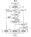
以上説明したハードウェア構成を前提として、第1実施形態の制御装置100は、図2に示した処理を行なう。図2は、エンジンの制御ルーチンを示すフローチャートである。ECU70は、エンジン10の運転が開始されると、図2に示した処理を繰り返し実行する。このルーチンの処理を開始すると、ECU70は、まずアクセルセンサー61や車速センサー64などのセンサーからの信号を入力し、アクセル踏込量αや車速Vなどを読み込む(ステップS100)。続いて、こうしたアクセル踏込量αや車速Vなどから、予混合燃焼モードで運転する領域であるか否かの判断を行なう(ステップS110)。一般に、予混合燃焼モードは低速・低負荷領域で採用され、エンジンの負荷が高い領域では拡散燃焼モードが選択される。何れの運転領域で、予混合燃焼モードでの運転を行なうかは、予め定め、マップの形式でROM72などに記憶している。このマップの一例を図3(A)に示した。
B. Engine control:
On the premise of the hardware configuration described above, the
図示するように、ここでは、エンジン10の負荷を、車速Vとアクセル踏込量αとにより定るものとし、車速Vとアクセル踏込量αとが小さい領域では、予混合燃焼モードによりエンジン10を運転し、車速Vとアクセル踏込量αとが大きい領域では、拡散燃焼モードによりエンジン10を運転するものとしている。図3(A)は、エンジン10に対して要求される負荷を車速Vとアクセル踏込量αとにより判断するマップとして構成したが、負荷に対するエンジン10の出力は、エンジン10の出力トルクTと回転数Nとの積として捉えることも可能である。この場合には、図3(A)は、トルクTと回転数Nとの二次元マップとして構成することができる。
As shown in the figure, here, the load of the
予混合燃焼モードでの運転を行なう領域であると判定すると(ステップS110:「YES」)、次に、モータリングまたは拡散燃焼モードで運転する領域から遷移したか否かの判断を行なう(ステップS120)。モータリングまたは拡散燃焼モードで運転する領域から遷移したときは、それまでエンジンがモータリング状態にあったか、または拡散燃焼モードによって運転されており、車両の運転状態が変化して、エンジン負荷が予混合燃焼モードで運転する領域に変化したことを意味する。 If it is determined that the region is to be operated in the premixed combustion mode (step S110: “YES”), it is next determined whether or not the region has been shifted from the region operated in the motoring or diffusion combustion mode (step S120). ). When a transition is made from a region that operates in motoring or diffusion combustion mode, the engine has been in motoring state until then, or has been operated in diffusion combustion mode, and the vehicle operation state has changed and the engine load has been premixed. It means that it has changed to the region that operates in the combustion mode.
拡散燃焼領域から予混合燃焼領域に遷移する場合の一例を、図3に、点A1〜A5として示した。エンジン10に対する要求負荷が、図3に示した点A1の場合には、拡散燃焼モードにより、エンジン10を運転し、要求負荷が次第に減少して、点A2→A3→A4と変化し、やがて点A5に至ると、予混合燃焼モードにより運転すると判断することになる。この燃焼領域の変化を時間軸に沿って示したのが、図3(B)である。この例では、時間と共に、エンジンの負荷は、拡散燃焼領域内で変化し、点A5では、予混合燃焼領域に入ったことが分かる。
An example of the transition from the diffusion combustion region to the premixed combustion region is shown as points A1 to A5 in FIG. When the required load on the
拡散燃焼領域から予混合燃焼領域に入った直後、即ち燃焼領域の遷移が起きたと判断された場合には(ステップS120:「YES」)、グロープラグ32への通電を行ない(ステップS200)、所定時間(本実施形態では約3秒)の経過を待つ(ステップS210)。所定時間待つのは、グロープラグ32の温度が1300度Cまで上昇するのを待つためである。本実施形態で用いたセラミックタイプのグロープラグ32は、およそ3秒あれば、1300度Cまで達する。この間は、拡散燃焼が継続されることになる。所定時間が経過すると、予混合燃焼モードに切り替える処理と、EGR率を増加する処理とを行なう(ステップS300)。予混合燃焼モードに切り替えると、ECU70は、第1,第2EGRバルブ37,22を制御し、EGR率を40〜80%に増大させる。EGR率は、排ガスが、第2EGRバルブ22を通る比較的短い経路、もしくは第1EGRバルブ37を通る長い経路を介して吸気側に供給されるので、何れの経路を通る場合でも、所定のEGR率に達するまでには相当の時間を要する。そこで、本実施形態では、EGR率が所定の値に達するまでの期間を、遷移期間としている。図3(B)に示したように、この遷移期間では、グロープラグ32は1300度Cに保たれる。EGRを行なった状態でのグロープラグ32への通電による作用効果については、燃料噴射時期制御(ステップS400)と共に、後述する。
Immediately after entering the premixed combustion region from the diffusion combustion region, that is, when it is determined that a transition of the combustion region has occurred (step S120: “YES”), the
他方、上記ステップS110,S120の判断において、車両の運転状態から見てエンジンが予混合燃焼モードにより運転する領域にないか(ステップS110:「NO」)、予混合燃焼モードで運転する領域にあっても、上記遷移期間にない場合(ステップS120:「NO」)には、ステップS130に移行して、それまでの制御を継続する。それまでの制御とは、拡散燃焼モードで運転していた場合には、そのまま拡散燃焼モードでの燃料噴射制御を継続し、予混合燃焼モードで運転していた場合には、そのまま予混合燃焼モードでの燃料噴射制御を継続することを意味している。なお、拡散燃焼モードや予混合燃焼モードでの燃焼は、従来から公知のものなので、詳しくは説明しない。もとより、同じ拡散燃焼モードや予混合燃焼モードにも、様々なバリエーションが存在するが、ステップS200、S210での処理を除けば、何れの制御でも適用可能である。 On the other hand, in the determinations in steps S110 and S120, whether the engine is not in a region where it operates in the premixed combustion mode as viewed from the vehicle operating state (step S110: “NO”), or is in a region where the engine is operated in the premixed combustion mode. However, when it is not in the transition period (step S120: “NO”), the process proceeds to step S130 and the control up to that point is continued. The previous control means that if the engine is operating in the diffusion combustion mode, the fuel injection control in the diffusion combustion mode is continued, and if it is operating in the premixed combustion mode, the premixed combustion mode is continued. This means that the fuel injection control is continued. The combustion in the diffusion combustion mode and the premixed combustion mode is conventionally known and will not be described in detail. Of course, there are various variations in the same diffusion combustion mode and premixed combustion mode, but any control can be applied except for the processing in steps S200 and S210.
ステップS130の後、所定時間が経過したか否かの判断を行ない(ステップS140)、所定時間が経過していれば、グロープラグ32への通電をオフする処理を行なう(ステップS220)。所定の時間の経過は、ここでは、予混合燃焼モードに切り替えられてからの時間により判断している。したがって、通常は遷移期間の終了と共に、グロープラグ32への通電はオフされる。予混合燃焼モードから拡散燃焼モードに移行したのち、所定期間が経過すれば、グロープラグに通電しておく必要はないと判断するのである。なお、遷移期間とグロープラグの通電時間(ステップS140:「所定時間」)とは、一致していても良いし、異なっていても差し支えない。
After step S130, it is determined whether or not a predetermined time has elapsed (step S140). If the predetermined time has elapsed, a process for turning off the energization of the
上述した処理の後、燃料噴射時期制御(ステップS400)を実行する。ディーゼルエンジン10にとって、燃料噴射時期は、燃焼状態に大きな影響を与える。もとより、燃料噴射量は、車速Vとアクセル踏込量αとにより決定される。本実施形態では、燃料噴射時期は、車両に要求されているトルクを確保できるように予め決定されている。車速Vとアクセル踏込量αとにより燃料噴射量を求めた上で、予め定めたマップを参照し、この燃料噴射量で必要なトルクが得られる燃料噴射時期での燃料噴射が行なわれる。この点を、図を用いて説明する。図4は、EGR率が約40%の場合に、グロープラグ32の加熱温度をパラメータとする燃料噴射時期とトルク(図示平均有効圧IMEP)との関係を示すグラフである。
After the process described above, fuel injection timing control (step S400) is executed. For the
本実施形態では、モータリングまたは拡散燃焼領域から予混合燃焼領域に遷移した直後に、グロープラグ32への通電を行ない、所定時間待ってから、予混合燃焼モードに切り替えている。つまり、グロープラグ32への通電は、拡散燃焼モードから拡散燃焼モードに切替える直前に行なわれることになる。グロープラグ32は、少なくとも所定時間経過すれば、1300度Cまでその温度を上昇する。したがって、同じIMEP値同士で比べると、グロープラグ32を1300度Cに通電した場合の燃料噴射時期は、グロープラグ32への通電を行なわない場合と比べて、1CA[deg]程度、燃料噴射時期を遅角(リタード)することができる。図4では、燃料噴射時期を遅角(リタード)−1CA[deg]に制御できることが分かる。なお、本実施形態では、グロープラグ32を少なくとも900度C程度まで上昇させることができれば、グロープラグ32への通電を行なわない場合と比べてトルク増大の効果は認められる。なお、グロープラグ32の到達温度を1000度C、1300度Cと高めていくと、トルク増大の効果が、より高まることが認められた。
In the present embodiment, immediately after the transition from the motoring or diffusion combustion region to the premixed combustion region, the
このように、本実施形態では、グロープラグ32への通電を行なうことで、グロープラグ32の温度が1300度Cまで上昇しているので、燃料噴射時期を遅角(リタード)することができる。燃料噴射時期を遅角すると、種々の望ましい効果をディーゼルエンジン10に生じさせる。各種特性の改善について、以下、図5ないし図10を用いて説明する。図5ないし図10は、何れも図4同様、EGR率が約40%での特性を示している。
As described above, in the present embodiment, since the temperature of the
(A)トルク変動の低減:
図5は、燃料噴射時期とサイクル変動(IMEP COV %)との関係を示すグラフである。図示するように、グロープラグ32への通電を行なってグロープラグ32の温度を1300度Cまで上昇させた状態で、1CA[deg]遅角されることで、グロープラグ32への通電を行なわず、且つ、燃料噴射時期を遅角しない状態と比較して、ディーゼルエンジン10のトルク変動は、低減される。
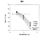
(B)図6は、グロープラグの加熱温度をパラメータとして、燃料噴射時期と燃焼ノイズとの関係を示すグラフである。図示するように、グロープラグ32への通電を行なってグロープラグ32の温度を1300度Cまで上昇させると、発生する燃焼ノイズは、グロープラグ32への通電を行なわない場合と比べて、増加するが、燃料噴射時期が1CA[deg]だけ遅角することにより、遅角せずかつグロープラグ32への通電を行なわない場合より、燃焼ノイズは低減される。遅角せずかつグロープラグ32への通電を行なわない場合の燃焼ノイズを、図6に、判定ラインDLとして記載した。1CA[deg]だけ遅角した場合、1300度Cでも、この判定ラインDLを下回っていることが分かる。なお、他の図7ないし図10においても、同様に、判定ラインDLを記載している。
(A) Reduction of torque fluctuation:
FIG. 5 is a graph showing the relationship between the fuel injection timing and the cycle variation (IMEP COV%). As shown in the drawing, when the
(B) FIG. 6 is a graph showing the relationship between the fuel injection timing and the combustion noise using the heating temperature of the glow plug as a parameter. As shown in the figure, when the
(C)図7はグロープラグの加熱温度をパラメータとして、燃料噴射時期とNOx発生量との関係を示すグラフである。図示するように、グロープラグ32への通電を行なってグロープラグ32の温度を1300度Cまで上昇させると、発生するNOxの量は、グロープラグ32への通電を行なわない場合と比べて、増加するが、燃料噴射時期が1CA[deg]だけ遅角することにより、遅角せずかつグロープラグ32への通電を行なわない場合(判定ラインDL)と同程度まで、NOxの発生量は低減される。
(D)図8は、グロープラグの加熱温度をパラメータとして、燃料噴射時期とCO発生量との関係を示すグラフである。図示するように、グロープラグ32への通電を行なってグロープラグ32の温度を1300度Cまで上昇させると、発生するCOの量は、グロープラグ32への通電を行なわない場合と比べて、低減する。もとより、燃料噴射時期を遅角側に制御すると、COの発生量は増加するが、燃料噴射時期を1CA[deg]だけ遅角しても、遅角せずかつグロープラグ32への通電を行なわない場合(判定ラインDL)より、COの発生量は低減される。
(C) FIG. 7 is a graph showing the relationship between the fuel injection timing and the NOx generation amount with the heating temperature of the glow plug as a parameter. As shown in the figure, when the
(D) FIG. 8 is a graph showing the relationship between the fuel injection timing and the CO generation amount with the heating temperature of the glow plug as a parameter. As shown in the figure, when the
(E)図9は、グロープラグの加熱温度をパラメータとして、燃料噴射時期とTHC発生量との関係を示すグラフである。図示するように、グロープラグ32への通電を行なってグロープラグ32の温度を1300度Cまで上昇させると、発生するTHCの量は、グロープラグ32への通電を行なわない場合と比べて、低減する。もとより、燃料噴射時期を遅角側に制御すると、THCの発生量は増加するが、燃料噴射時期を1CA[deg]だけ遅角しても、遅角せずかつグロープラグ32への通電を行なわない場合(判定ラインDL)より、THCの発生量は低減される。
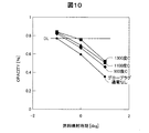
(F)図10は、グロープラグの加熱温度をパラメータとして、燃料噴射時期と煤発生量(OPACITY)との関係を示すグラフである。図示するように、グロープラグ32への通電を行なってグロープラグ32の温度を1300度Cまで上昇させると、発生する煤の量は、グロープラグ32への通電を行なわない場合と比べて、増加するが、燃料噴射時期が1CA[deg]だけ遅角することにより、遅角せずかつグロープラグ32への通電を行なわない場合(判定ラインDL)と比べて、発生する煤の量をほぼ同程度にすることができる。
(E) FIG. 9 is a graph showing the relationship between the fuel injection timing and the THC generation amount with the heating temperature of the glow plug as a parameter. As shown in the figure, when energization of the
(F) FIG. 10 is a graph showing the relationship between the fuel injection timing and the soot generation amount (OPACITY) using the heating temperature of the glow plug as a parameter. As shown in the figure, when energization of the
以上説明したように、本実施形態によれば、車両の負荷が低下して、ディーゼルエンジン10を予混合燃焼すべき領域に遷移すると、グロープラグ32への通電を行なってグロープラグ32の温度を上昇し、かつ燃料噴射時期を1CA[deg]だけ遅角側に制御している。この結果、必要なエンジントルクを確保したまま、トルク変動(図5)、燃焼ノイズ(図6)、NOxの発生量(図7)、COの発生量(図8)、THCの発生量(図9)などを、グロープラグ32への通電を行なわない場合と比べて、低減することができるという優れた効果を奏する。
As described above, according to the present embodiment, when the load of the vehicle is reduced and the
C.変形例:
C−1)変形例1:
上記実施例では、グロープラグ32としてセラミックタイプのものを用い、グロープラグ32の温度を1300度Cまで上昇するものとしたが、各図に示したように、グロープラグによる加熱温度は、少なくとも900度Cあれば良く、1100度C以上であれば、なお好ましい。900度C程度の加熱温度であれば、メタルタイプのグロープラグによっても達成可能である。
C. Variation:
C-1) Modification 1:
In the above embodiment, a ceramic type is used as the
C−2)変形例2:
上記実施形態では、グロープラグへの通電を行なうと共に、燃料噴射時期を遅角したが、燃料噴射時期を遅角せず、大きなトルクを取り出すものとしても良い。あるいは、エンジン10から取り出すトルクはそのままに燃料噴射量を、その分低減しても良い。
C-2) Modification 2:
In the above embodiment, the glow plug is energized and the fuel injection timing is retarded. However, a large torque may be extracted without delaying the fuel injection timing. Alternatively, the fuel injection amount may be reduced correspondingly while the torque extracted from the
C−3)変形例3:
上記実施形態では、車速Vとアクセル踏込量αとにより予混合燃焼領域か否かの判断を行ない、グロープラグ32への通電を行なった後、温度上昇に必要な時間(例えば3秒)だけ待機してから、予混合燃焼モードでの運転に切り替えた。これに対して、待機する時間を3秒未満、例えば0.1秒〜2.5秒程度まで短縮しても差し支えない。特に、グロープラグの性能が高く、短時間に高温に達するものを採用していれば、その分だけ待機時間を短くすることができる。また、グロープラグに加熱時より小さい電力を供給して予熱しておき、短時間のうちに所定の温度まで上昇させるものとしても良い。
C-3) Modification 3:
In the above embodiment, whether or not the premixed combustion region is determined based on the vehicle speed V and the accelerator depression amount α, energizes the
C−4)変形例4:
グロープラグへの通電は、予混合燃焼領域(図3(A))に入ってから行なうのではなく、エンジンへの要求負荷の変化を予測して、予混合燃焼領域に入る前に行っても良い。図3(A)に示した例では、車速Vとアクセル踏込量αとが、点A1→A2→A3→A4と変化してくれば、やがて予混合燃焼領域に入るであろうと予測することができる。こうした予測を行なってグロープラグへの通電を行なえば、早期に予混合燃焼モードでの運転に切り替えることができ、燃費の改善に資することができる。また、上記実施形態では、図3(B)に実線GAとして示したように、遷移期間が終わると、グロープラグ32への通電をオフしたが、必ずしも遷移期間の終了と共に、直ちに通電をオフする必要はない。予混合燃焼モードでの運転中、グロープラグ32への通電をそのまま継続しても良いし、図3(B)に、破線GBとして示したように、供給する電力量を下げて、上昇温度を1300度C以下、例えば900度C程度に抑えて継続しても良い。暖気運転時など、エンジンや触媒がまだ十分に暖気されていない場合には、グロープラグ32への通電を継続すると、THCの発生量を低減できる。あるいは、一旦電力の供給をオフとし、必要に応じて、一点鎖線GCとして示したように、再通電して、グロープラグ32を所定温度まで加熱するものとしても良い。例えば、排気通路に設けられたセンサーからの信号により、触媒が十分な活性を示していないと判断された場合に、グロープラグ32への通電を再開するものとしても良い。
C-4) Modification 4:
Energization of the glow plug is not performed after entering the premixed combustion region (FIG. 3A), but may be performed before entering the premixed combustion region by predicting a change in the required load on the engine. good. In the example shown in FIG. 3A, if the vehicle speed V and the accelerator depression amount α change from the point A1 → A2 → A3 → A4, it is predicted that the vehicle will soon enter the premixed combustion region. it can. By conducting such a prediction and energizing the glow plug, it is possible to switch to the operation in the premixed combustion mode at an early stage, which can contribute to the improvement of fuel consumption. In the above embodiment, as indicated by the solid line GA in FIG. 3B, the energization to the
C−5)変形例5:
上記実施形態では、予混合燃焼モードでの燃料噴射時期は、予め定めておくものとしたが、各種パラメータを用いたフィードバック制御により決定するものとしても良い。フィードバック制御のためのパラメータとしては、トルクやトルク変動、NOx発生量なども用いることができるが、グロープラグ32に設けられた筒内圧センサーからの信号を利用して、圧力上昇率最大値dPmaxを演算し、これを所定の範囲とするようにフィードバック制御することも望ましい。圧力上昇率最大値dPmaxは、予混合燃焼時の燃料噴射時期を制御する指標として、優れているからである。圧力上昇率最大値dPmaxは、EGR率をパラメータとして、燃料噴射時期に強い相関を示す。したがって、この圧力上昇率最大値dPmaxが目標値dPmaxとなるように燃料噴射時期をフィードバック制御すると、燃焼ノイズ、NOxの発生量、COの発生量、煤(OPACITY)などを抑制することができる。
C-5) Modification 5:
In the above embodiment, the fuel injection timing in the premixed combustion mode is determined in advance, but may be determined by feedback control using various parameters. As parameters for feedback control, torque, torque fluctuation, NOx generation amount, and the like can be used. However, by using a signal from an in-cylinder pressure sensor provided in the
しかも、圧力上昇率最大値dPmaxによる燃料噴射時期のフィードバック制御を、グロープラグ32を加熱して温度上昇させた状態で行なうと、更に好ましいことが見い出された。図11は、グロープラグ32の上昇温度をパラメータとして、燃料噴射時期と圧力上昇率最大値dPmaxとの関係を示すグラフ(図11上段)と、同じくグロープラグ32の上昇温度をパラメータとして、燃料噴射時期とトルク(図示平均有効圧IMEP)との関係を示すグラフ(図11下段)である。なお、EGR率は、この例では、30%であった。
In addition, it has been found that it is more preferable to perform feedback control of the fuel injection timing with the maximum pressure increase rate value dPmax in a state where the temperature is increased by heating the
図11から分かるように、グロープラグ32の上昇温度が変わると、燃料噴射時期と圧力上昇率最大値dPmaxとの関係は変化するものの、圧力上昇率最大値dPmaxを目標範囲に制御するための燃料噴射時期の制御範囲CAa,CAbは、グロープラグ32の上昇温度に寄らず、略同一である。しかし、燃料噴射時期の制御範囲CAa,CAbにおける図示平均有効圧IMEPの変動ΔIa,ΔIbは、図11下段に示したように、グロープラグ32の上昇温度が高いほど小さくなる(ΔIb<ΔIa)。したがって、予混合燃焼モードでエンジン10を制御する際、圧力上昇率最大値dPmaxを用いて燃料噴射時期をフィードバック制御することで、エンジン10を好適に運転でき、更にグロープラグ32への通電を行なうことで、燃焼ノイズの低減を初めとして、NOxの発生量、COの発生量、煤(OPACITY)、トルク変動などを一層低減することができる。
As can be seen from FIG. 11, when the rising temperature of the
上述した圧力上昇率最大値dPmaxに代えて、あるいは圧力上昇率最大値dPmaxと共に、熱発生率最大値dQmaxを用いても良い。また、これらのパラメータを用いて制御する場合、予め、EGR率と圧力上昇率最大値dPmax(あるいは熱発生率最大値dQmax)と燃料噴射時期との相関を求めてマップ用意し、これに基づいて、フィードバック制御を行なってもよいが、例えば以下のように、簡便な制御を用いても良い。この場合、まず、圧力上昇率最大値dPmaxの目標値を定めておき、筒内圧センサーからの信号を処理して得られた圧力上昇率最大値dPmaxと目標値との大小を比較する。圧力上昇率最大値dPmaxが、目標値を超えていれば予混合燃焼モードにおける燃料噴射時期を所定CA角度だけ遅角側に制御し、目標値未満であれば所定CA角度だけ進角側に制御する。こうした簡便な制御によって、適正な燃料噴射時期を実現実現することができる。 Instead of the pressure increase rate maximum value dPmax described above, or together with the pressure increase rate maximum value dPmax, the heat release rate maximum value dQmax may be used. When the control is performed using these parameters, a map is prepared in advance by obtaining a correlation between the EGR rate, the pressure increase rate maximum value dPmax (or the heat release rate maximum value dQmax), and the fuel injection timing. Although feedback control may be performed, for example, simple control may be used as follows. In this case, first, a target value of the pressure increase rate maximum value dPmax is determined, and the pressure increase rate maximum value dPmax obtained by processing the signal from the in-cylinder pressure sensor is compared with the target value. If the maximum pressure rise rate dPmax exceeds the target value, the fuel injection timing in the premixed combustion mode is controlled to the retard side by a predetermined CA angle, and if it is less than the target value, the fuel injection timing is controlled to the advance side by the predetermined CA angle. To do. An appropriate fuel injection timing can be realized by such simple control.
C−6)変形例6:
上記実施形態では、グロープラグへの通電は予混合燃焼モードへの遷移時に行なったが、EGR率が所定以上、例えば60%以上となったときに実施するものとして良い。EGR率は、酸素濃度センサー53からの信号に基づいて求めることができる。あるいは、第1,第2EGRバルブ37,22の開度から予測しても良い。またグロープラグへの通電を行なうEGR率としては、60%より小さくても大きくても良い。ディーゼルエンジンの特性に応じて、決定すればよい。
C-6) Modification 6:
In the above embodiment, energization of the glow plug is performed at the time of transition to the premixed combustion mode. However, it may be performed when the EGR rate is equal to or higher than a predetermined value, for example, 60%. The EGR rate can be obtained based on a signal from the
D.第2実施形態:
次に本願発明の第2実施形態について説明する。第2実施形態のエンジンの制御装置100は、第1実施形態の制御装置と同一の構成を備え、エンジン制御ルーチンのみ異なる。第2実施形態におけるエンジン制御ルーチンを図12に示した。
D. Second embodiment:
Next, a second embodiment of the present invention will be described. The
第2実施形態のエンジンの制御装置100を構成するECU70は、エンジン10が起動すると、図12に示した制御ルーチンを繰り返し実行する。このルーチンを起動すると、ECU70は、第1実施形態と同様に、まず車両におけるアクセルセンサー61や車速センサー64などのセンサーからの信号を入力し、アクセル踏込量αや車速Vなどを読み込む(ステップS500)。続いて、こうしたアクセル踏込量αや車速Vなどから、燃焼形態についての判断を行なう(ステップS510)。
ECU70 which comprises the
ここでいう燃焼形態についての判断は、現在の燃焼形態と、次に実現すべき燃焼形態(目標燃焼形態)とがどのようなものであるか、という判断である。図3に示したように、一般に、予混合燃焼モードは低速・低負荷領域で採用され、エンジンの負荷が高い領域では拡散燃焼モードが選択される。何れの運転領域で、予混合燃焼モードでの運転を行なうかは、予め定め、マップの形式でROM72などに記憶している。図3には、エンジン10の挙動の一例を示しているが、この例に沿って例示すると、燃焼形態の判断は次のようになる。
The judgment about the combustion mode here is a judgment of what the current combustion mode and the combustion mode (target combustion mode) to be realized next are. As shown in FIG. 3, generally, the premixed combustion mode is adopted in the low speed / low load region, and the diffusion combustion mode is selected in the region where the engine load is high. In which operating region the operation in the premixed combustion mode is determined in advance and stored in the
(1)例えば図3にA3で示した状態から負荷が変化しなかったり、変化したとしてもA4に示した状態に移行したとすれば、現在の燃焼形態は拡散燃焼であり、目標燃焼形態も拡散燃焼、となる。
(2)例えば図3にA4で示した状態からA5に示した状態に移行したとすれば、現在の燃焼形態は拡散燃焼であり、目標燃焼形態は予混合燃焼、となる。
(3)例えば図3にA5で示した状態から負荷が変化しなかったり、変化したとしてもA5より更に負荷の小さな状態に移行したとすれば、現在の燃焼形態は予混合燃焼であり、目標燃焼形態も予混合燃焼、となる。
(4)例えば図3にA5で示した状態からA4に示した状態に移行したとすれば、現在の燃焼形態は予混合燃焼であり、目標燃焼形態は拡散燃焼、となる。但し、本実施形態では、(4)は、拡散燃焼である制御を行なうものとして、(1)と同様に制御する。
(1) For example, if the load does not change from the state indicated by A3 in FIG. 3 or if the load changes to the state indicated by A4, the current combustion mode is diffusion combustion, and the target combustion mode is also It becomes diffusion combustion.
(2) For example, if the state indicated by A4 in FIG. 3 is shifted to the state indicated by A5, the current combustion mode is diffusion combustion, and the target combustion mode is premixed combustion.
(3) For example, if the load does not change from the state shown by A5 in FIG. 3 or even if it changes, the current combustion form is premixed combustion, and the target combustion mode is the target combustion. The combustion mode is also premixed combustion.
(4) For example, if the state indicated by A5 in FIG. 3 is shifted to the state indicated by A4, the current combustion mode is premixed combustion, and the target combustion mode is diffusion combustion. However, in this embodiment, (4) is controlled in the same manner as (1), assuming that the control is diffusion combustion.
(1)(4)のケースでは、拡散燃焼の制御を継続する(ステップS530)。拡散燃焼では、上死点(TDC)付近で筒内に燃料を噴射する。燃料噴射量や噴射時期は、要求負荷(車速とアクセル踏み込み量など)に応じて予め定められているものとして良い。なお、拡散燃焼においては、EGR率は低い値とされている。 (1) In the case of (4), the diffusion combustion control is continued (step S530). In diffusion combustion, fuel is injected into the cylinder near the top dead center (TDC). The fuel injection amount and the injection timing may be determined in advance according to the required load (vehicle speed, accelerator depression amount, etc.). In diffusion combustion, the EGR rate is a low value.
(2)のケース、即ち、現在の燃焼形態が拡散燃焼であり、目標燃焼形態が予混合燃焼である場合には、第1実施形態と同様、グロープラグ32への通電をオン状態とする(ステップS550)。通電が開始されると、本実施形態で用いたセラミックヒーターを用いたグロープラグ32では、その温度は急速に上昇する。こうしたセラミックヒーターと圧力センサーとを備えたグロープラグ32としては、例えば特開2013−257133号公報などに示されたグロープラグがある。こうしたグロープラグ32では、所定温度(例えば1000℃)まで達する時間は、数秒程度で済む。そこで、続いて、グロープラグ32への通電時間について判定する(ステップS560)。グロープラグ32への通電時間が所定時間経過していなければ、既に説明した拡散燃焼の制御(ステップS530)に移行し、拡散燃焼を継続するものとし、「NEXT」に抜けて、本制御ルーチンを一旦終了する。
In the case of (2), that is, when the current combustion mode is diffusion combustion and the target combustion mode is premixed combustion, the energization to the
図12に示した制御ルーチンが繰り返し実行されていると、グロープラグ32への通電時間は、やがて所定時間を経過する。所定時間は、グロープラグ32が通電開始から1000℃に達するまでの時間を目安に、例えば3秒程度に設定されている。グロープラグ32への通電が開始されてから所定時間が経過すると、ステップS560では、「所定時間経過」と判断し、予混合燃焼モードへの切り替えとEGR率を増大する処理とを行なう(ステップS570)。この処理は、第1実施形態で示した処理(図2、ステップS300)と基本的に同じである。その後、更にステップS600に進み、過渡時の燃料噴射時期制御を実施する。ステップS600の過渡時の燃料噴射時期制御は、第1実施形態のC−5)変形例5として説明した処理、即ち圧力上昇率最大値または熱発生率最大値を用いて、燃料噴射時期をフィードバック制御するものである。制御としては、基本的に第1実施形態の制御(図2、ステップS400)に対応している。過渡時の燃料噴射時期制御を実行した後、「NEXT」に抜けて本制御ルーチンを一旦終了する。
When the control routine shown in FIG. 12 is repeatedly executed, the energization time to the
次に、本制御ルーチンが起動されると、燃焼モードは、予混合燃焼モードに切り替えられているから(ステップS570)、ステップS510での判断は、(3)のケース、即ち現在の燃焼状態が予混合燃焼であり、目標燃焼状態も予混合燃焼となる。この場合には、まず制御が収束しているか否かの判断を行なう(ステップS610)。予混合燃焼に切り替えられると、次第にEGR率は上昇し、圧力上昇率最大値または熱発生率最大値による制御は収束して行くが、収束までには一定の時間を要する。制御が収束するまでは、過渡時の燃料噴射時期制御(ステップS600)を継続する。本実施形態において、制御が収束したとは、圧力上昇率最大値または熱発生率最大値が目標範囲に収まった場合、あるいは燃料噴射時期の変更に対して圧力上昇率最大値などの感度がなくなった場合を意味している。 Next, when this control routine is started, the combustion mode is switched to the premixed combustion mode (step S570), so the judgment in step S510 is the case of (3), that is, the current combustion state. This is premixed combustion, and the target combustion state is also premixed combustion. In this case, it is first determined whether or not the control has converged (step S610). When the premixed combustion is switched, the EGR rate gradually increases and the control based on the maximum value of the pressure increase rate or the maximum value of the heat generation rate converges, but it takes a certain time to converge. Until the control converges, the fuel injection timing control at the time of transition (step S600) is continued. In this embodiment, the control has converged when the maximum value of the pressure increase rate or the maximum value of the heat generation rate falls within the target range, or the sensitivity such as the maximum value of the pressure increase rate is lost when the fuel injection timing is changed. It means that.
他方、制御が収束したと判断された場合には(ステップS610:「YES」)、これまで通電を継続していたグロープラグ32への通電を停止する(ステップS620)。その後、過渡時の制御は終了したとして、予混合燃焼の制御を開始・継続する(ステップS630)。予混合燃焼では、低負荷時の燃料噴射量を求め、これをパイロット噴射とメイン噴射に分けて、予め定めた噴射時期で噴射する。その後、「NEXT」に抜けて、本制御ルーチンを一旦終了する。以後も、ディーゼルエンジン10が運転されている限り、本制御ルーチンを繰り返し実行し、燃焼状態とその遷移に基づき、グロープラグ32への通電や、EGR率の制御、更には、拡散燃焼、予混合燃焼および過渡時の制御のいずれかを実行する。
On the other hand, when it is determined that the control has converged (step S610: “YES”), the energization to the
以上説明した第2実施形態としてのエンジン制御装置100によれば、図12に示した制御ルーチンを繰り返し実行しながら、ディーゼルエンジン10の運転状態により、拡散燃焼モードで制御、予混合燃焼モードでの制御、過渡時の燃焼制御を適切に行ない、かつグロープラグ32への通電を的確に制御することができる。この結果、第1実施形態と同様の効果を奏する上、制御を、より的確に行なうことができる。
According to the
E.燃料噴射時期の設計:
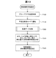
次に本発明の第3の実施形態として、燃料噴射時期を設計する方法について説明する。図13は、燃料噴射時期の設計の工程を示す工程図である。所定のエンジンにおける燃料噴射時期を設計する場合、まず図1に示したように、エンジン10を、実際に運転される吸排気系20に組み込み、グロープラグの温度を制御する(ステップT100)。ここでは、グロープラグの実際の温度が分かるように、熱電対などの温度検出手段をエンジンに組み込んでおくことも望ましい。
E. Fuel injection timing design:
Next, a method for designing the fuel injection timing will be described as a third embodiment of the present invention. FIG. 13 is a process diagram showing a process for designing the fuel injection timing. When designing the fuel injection timing in a predetermined engine, first, as shown in FIG. 1, the
次に、予混合燃焼モードでエンジンを運転する(ステップT110)。運転に際して、EGR率を実際と同様に漸増させる。そして、エンジン10に設けた各種センサーからのデータを収集する(ステップT200)。各種データには、図1に示したセンサーの他、計測のために特に設けられたセンサーからのデータが含まれても良い。例えば、燃料のセタン価を検出するセンサーなどが考えられる。
Next, the engine is operated in the premixed combustion mode (step T110). During operation, the EGR rate is gradually increased as in the actual case. And the data from the various sensors provided in the
次に、得られたデータから、エンジンの出力、トルク変動、燃焼ノイズ、NOx、CO、THC、煤の各発生量を総合的に判断して、各EGR率での燃料噴射時期を決定する(ステップT310)。かかる処理を、繰り返し、また更に、グロープラグの温度を変えて、実行し、予混合燃焼モードとなった際の遷移状態での燃料噴射時期を、マップの形にして、設定する(ステップT320)。こうして得られたマップは、実際にエンジン10を制御する制御装置であるECU70のROM72に書き込んで提供される。ECU70は、予混合燃焼モードへ遷移したとき、ROM72に書き込まれたマップを参照して、燃料噴射時期を制御する。
Next, from the obtained data, the engine output, torque fluctuation, combustion noise, NOx, CO, THC, and soot generation amount are comprehensively determined to determine the fuel injection timing at each EGR rate ( Step T310). This process is repeated and further performed by changing the temperature of the glow plug, and the fuel injection timing in the transition state when the premixed combustion mode is set is set in the form of a map (step T320). . The map thus obtained is provided by being written in the
以上説明した燃料噴射時期の設計方法によれば、予混合燃焼モードへ遷移する際の燃料噴射時期を、グロープラグの加熱温度に合わせて、好ましい特性が得られるように決定することができる。この結果、第1実施形態で説明したように、必要なトルクを確保した上で、トルク変動や燃焼ノイズ等を低減した予混合燃焼モードでのエンジンの運転が可能となる。 According to the fuel injection timing design method described above, the fuel injection timing at the time of transition to the premixed combustion mode can be determined so as to obtain preferable characteristics in accordance with the heating temperature of the glow plug. As a result, as described in the first embodiment, it is possible to operate the engine in the premixed combustion mode in which the required torque is ensured and torque fluctuation, combustion noise and the like are reduced.
F.変形例:
上記燃料噴射時期の設計方法では、燃料噴射時期の決定に、エンジンの出力、トルク変動、燃焼ノイズ、NOx、CO、THC、煤の各発生量を総合的に考慮したが、これらのパラメータのうち、少なくとも1つを考慮して決定してすれば良い。あるいは、更に多くのパラメータを考慮しても良い。例えば、燃焼質量割合(MFB)や熱発生率などを考慮してもよい。
F. Variation:
In the fuel injection timing design method described above, the engine output, torque fluctuation, combustion noise, NOx, CO, THC, and soot generation amount are comprehensively considered in determining the fuel injection timing. Of these parameters, The determination may be made in consideration of at least one. Alternatively, more parameters may be considered. For example, a combustion mass ratio (MFB), a heat generation rate, or the like may be considered.
本発明は、上述の実施形態や実施例、変形例に限られるものではなく、その趣旨を逸脱しない範囲において種々の構成で実現することができる。例えば、発明の概要の欄に記載した各形態中の技術的特徴に対応する実施形態、実施例、変形例中の技術的特徴は、上述の課題の一部又は全部を解決するために、あるいは、上述の効果の一部又は全部を達成するために、適宜、差し替えや、組み合わせを行うことが可能である。また、その技術的特徴が本明細書中に必須なものとして説明されていなければ、適宜、削除することが可能である。 The present invention is not limited to the above-described embodiments, examples, and modifications, and can be realized with various configurations without departing from the spirit thereof. For example, the technical features in the embodiments, examples, and modifications corresponding to the technical features in each embodiment described in the summary section of the invention are to solve some or all of the above-described problems, or In order to achieve part or all of the above effects, replacement or combination can be performed as appropriate. Further, if the technical feature is not described as essential in the present specification, it can be deleted as appropriate.
10…ディーゼルエンジン
11…ギヤホイール
12…吸気管
14…吸気パルプ
15…ターボチャージャー
17…インタークーラー
18…インタークーラー通路絞り弁
20…吸排気系
21…マニフォールド
22…第2EGRバルブ
24…燃料供給ポンプ
26…コモンレール
30…燃料噴射弁
32…グロープラグ
33…分岐管
34…酸化触媒
36…DPF
37…第1EGRバルブ
38…排気シャッター
51…吸気温センサー
52…吸気圧センサー
53…酸素濃度センサー
55…排気温センサー
57…不透明度センサー
59…NOxセンサー
61…アンクセルセンサー
62…アクセル
64…車速センサー
70…ECU
71…CPU
72…ROM
73…RAM
74…CAN
75…入力ポート
76…出力ポート
80…車内LAN
100…ディーゼルエンジンの制御装置
DESCRIPTION OF
37 ...
71 ... CPU
72 ... ROM
73 ... RAM
74 ... CAN
75 ...
100 ... Diesel engine control device
Claims (3)
前記ディーゼルエンジンの筒内を加熱する筒内ヒーターの加熱温度および前記ディーゼルエンジンにおけるEGR率をパラメータとして、予混合燃焼モードに切り替える際の燃料噴射時期制御の遅角限界を測定し、
前記測定の結果に基づき、前記ディーゼルエンジンを予混合燃焼モードに切り替える際の前記筒内ヒーターによる筒内の加熱温度を所定温度とした場合の、前記EGR率毎の前記ディーゼルエンジンの燃料噴射時期制御の進角量を決定し、
前記ディーゼルエンジンを予混合燃焼モードに切り替えた際に、前記決定した進角量で前記ディーゼルエンジンの燃料噴射時期を制御するように、制御ユニットを設計する
ディーゼルエンジンの制御装置の設計方法。 A control device design method for controlling combustion of a diesel engine,
Using the heating temperature of the in-cylinder heater that heats the inside of the cylinder of the diesel engine and the EGR rate in the diesel engine as parameters, the delay limit of the fuel injection timing control when switching to the premixed combustion mode is measured,
Based on the result of the measurement , fuel injection timing control of the diesel engine for each EGR rate when the in-cylinder heating temperature by the in-cylinder heater when switching the diesel engine to the premixed combustion mode is set to a predetermined temperature Determine the advance amount of
A method for designing a control device for a diesel engine, wherein a control unit is designed to control a fuel injection timing of the diesel engine with the determined advance amount when the diesel engine is switched to a premixed combustion mode.
請求項1記載のディーゼルエンジンの制御装置の設計方法。 The control of the fuel injection timing in the control unit is performed when the fuel injection timing is changed for each EGR rate on the assumption that the heating temperature of the in-cylinder heater is the predetermined temperature when switching to the premixed combustion mode. The method for designing a control device for a diesel engine according to claim 1, wherein the timing is controlled to the determined advance amount.
請求項1または請求項2記載のディーゼルエンジンの制御装置の設計方法。 Based on the measured retardation limit, the advance amount of the fuel injection timing by the control unit is suppressed by at least one of combustion noise of the diesel engine or NOx, CO, THC, and soot in the exhaust. The method for designing a control device for a diesel engine according to claim 1 or 2.
Priority Applications (3)
| Application Number | Priority Date | Filing Date | Title |
|---|---|---|---|
| JP2014130971A JP6467149B2 (en) | 2014-03-26 | 2014-06-26 | Diesel engine control device design method |
| EP15158910.8A EP2927464A1 (en) | 2014-03-26 | 2015-03-13 | Diesel engine control apparatus, diesel engine control method, and method for designing diesel engine control apparatus |
| US14/668,311 US20150275811A1 (en) | 2014-03-26 | 2015-03-25 | Diesel engine control apparatus, diesel engine control method, and method for designing diesel engine control apparatus |
Applications Claiming Priority (3)
| Application Number | Priority Date | Filing Date | Title |
|---|---|---|---|
| JP2014063743 | 2014-03-26 | ||
| JP2014063743 | 2014-03-26 | ||
| JP2014130971A JP6467149B2 (en) | 2014-03-26 | 2014-06-26 | Diesel engine control device design method |
Publications (2)
| Publication Number | Publication Date |
|---|---|
| JP2015194146A JP2015194146A (en) | 2015-11-05 |
| JP6467149B2 true JP6467149B2 (en) | 2019-02-06 |
Family
ID=52807544
Family Applications (1)
| Application Number | Title | Priority Date | Filing Date |
|---|---|---|---|
| JP2014130971A Expired - Fee Related JP6467149B2 (en) | 2014-03-26 | 2014-06-26 | Diesel engine control device design method |
Country Status (3)
| Country | Link |
|---|---|
| US (1) | US20150275811A1 (en) |
| EP (1) | EP2927464A1 (en) |
| JP (1) | JP6467149B2 (en) |
Families Citing this family (4)
| Publication number | Priority date | Publication date | Assignee | Title |
|---|---|---|---|---|
| JP6405846B2 (en) * | 2014-09-30 | 2018-10-17 | 三菱自動車工業株式会社 | Engine control device |
| GB2551528A (en) * | 2016-06-21 | 2017-12-27 | Jaguar Land Rover Ltd | Control system for a vehicle and method |
| CN106294964A (en) * | 2016-08-05 | 2017-01-04 | 重庆长安汽车股份有限公司 | A kind of analysis method determining intake manifold pressure sensor position |
| JP6842284B2 (en) * | 2016-11-30 | 2021-03-17 | 三菱重工業株式会社 | Marine diesel engine |
Family Cites Families (10)
| Publication number | Priority date | Publication date | Assignee | Title |
|---|---|---|---|---|
| JP2864896B2 (en) * | 1992-10-01 | 1999-03-08 | 日産自動車株式会社 | Control unit for diesel engine |
| DE60116546T2 (en) * | 2000-05-17 | 2006-08-24 | Toyota Jidosha K.K., Toyota | Internal combustion engine |
| JP3885545B2 (en) * | 2001-10-12 | 2007-02-21 | 日産自動車株式会社 | Exhaust gas purification device for internal combustion engine |
| JP2004011584A (en) * | 2002-06-10 | 2004-01-15 | Toyota Motor Corp | Fuel injection control device |
| JP4730122B2 (en) | 2006-02-07 | 2011-07-20 | いすゞ自動車株式会社 | Engine control method and engine control system |
| US7690368B2 (en) * | 2006-06-16 | 2010-04-06 | Ford Global Technologies, Llc | System and method for facilitating homogeneous charge compression ignition |
| JP5196270B2 (en) | 2009-03-31 | 2013-05-15 | マツダ株式会社 | Combustion control device and combustion control method for diesel engine |
| WO2010122643A1 (en) * | 2009-04-22 | 2010-10-28 | トヨタ自動車株式会社 | Controller of internal combustion engine |
| JP5396144B2 (en) * | 2009-05-14 | 2014-01-22 | 日本特殊陶業株式会社 | Glow plug energization control device and glow plug |
| JP6166093B2 (en) | 2012-05-14 | 2017-07-19 | 日本特殊陶業株式会社 | Glow plug with pressure sensor |
-
2014
- 2014-06-26 JP JP2014130971A patent/JP6467149B2/en not_active Expired - Fee Related
-
2015
- 2015-03-13 EP EP15158910.8A patent/EP2927464A1/en not_active Withdrawn
- 2015-03-25 US US14/668,311 patent/US20150275811A1/en not_active Abandoned
Also Published As
| Publication number | Publication date |
|---|---|
| EP2927464A1 (en) | 2015-10-07 |
| US20150275811A1 (en) | 2015-10-01 |
| JP2015194146A (en) | 2015-11-05 |
Similar Documents
| Publication | Publication Date | Title |
|---|---|---|
| US7769525B2 (en) | Apparatus and method for controlling a homogeneous charge compression-ignited internal-combustion engine | |
| JP6320209B2 (en) | Diesel engine control device and control method thereof | |
| US7246596B2 (en) | Control system for internal combustion engine | |
| US20020162320A1 (en) | Direct-injection spark-ignition engine with a turbo charging device | |
| JP2006112424A (en) | Engine | |
| JP6467149B2 (en) | Diesel engine control device design method | |
| JP2009041488A (en) | Control device of internal combustion engine | |
| EP2225451B1 (en) | Fuel injection control apparatus of internal combustion engine | |
| JP6302715B2 (en) | Diesel engine control apparatus and method | |
| JP2009041540A (en) | Control device of gasoline engine | |
| JP4379286B2 (en) | In-cylinder direct injection spark ignition internal combustion engine controller | |
| JP4643967B2 (en) | In-cylinder direct injection spark ignition internal combustion engine controller | |
| JP4290715B2 (en) | Control device for internal combustion engine | |
| JP5720479B2 (en) | Control device for internal combustion engine | |
| JP5158245B1 (en) | Combustion control device | |
| JP2010013953A (en) | Control device and control method | |
| JP4615503B2 (en) | Control device for internal combustion engine | |
| JP5831160B2 (en) | Control device for internal combustion engine | |
| JP7238571B2 (en) | Engine control method and engine control device | |
| JP6866871B2 (en) | Engine control device and control method | |
| JP5229429B1 (en) | Fuel property determination device for internal combustion engine | |
| JP5045482B2 (en) | Exhaust purification device and exhaust purification method | |
| JP2010190119A (en) | Combustion control device for diesel engine | |
| JP2007332815A (en) | Control unit of diesel engine | |
| JP2019183770A (en) | Engine low temperature oxidation reaction detection method and control method, engine low temperature oxidation reaction detection device and control device |
Legal Events
| Date | Code | Title | Description |
|---|---|---|---|
| A621 | Written request for application examination |
Free format text: JAPANESE INTERMEDIATE CODE: A621 Effective date: 20170412 |
|
| A131 | Notification of reasons for refusal |
Free format text: JAPANESE INTERMEDIATE CODE: A131 Effective date: 20180130 |
|
| A977 | Report on retrieval |
Free format text: JAPANESE INTERMEDIATE CODE: A971007 Effective date: 20180130 |
|
| A521 | Request for written amendment filed |
Free format text: JAPANESE INTERMEDIATE CODE: A523 Effective date: 20180323 |
|
| A02 | Decision of refusal |
Free format text: JAPANESE INTERMEDIATE CODE: A02 Effective date: 20180904 |
|
| A521 | Request for written amendment filed |
Free format text: JAPANESE INTERMEDIATE CODE: A523 Effective date: 20181121 |
|
| A911 | Transfer to examiner for re-examination before appeal (zenchi) |
Free format text: JAPANESE INTERMEDIATE CODE: A911 Effective date: 20181129 |
|
| TRDD | Decision of grant or rejection written | ||
| A01 | Written decision to grant a patent or to grant a registration (utility model) |
Free format text: JAPANESE INTERMEDIATE CODE: A01 Effective date: 20181218 |
|
| A61 | First payment of annual fees (during grant procedure) |
Free format text: JAPANESE INTERMEDIATE CODE: A61 Effective date: 20190111 |
|
| R150 | Certificate of patent or registration of utility model |
Ref document number: 6467149 Country of ref document: JP Free format text: JAPANESE INTERMEDIATE CODE: R150 |
|
| LAPS | Cancellation because of no payment of annual fees |