【0001】
【発明の属する技術分野】
本発明は、筒内と吸気管内に燃料を噴射する装置をそれぞれ備えるディーゼルエンジンの燃料噴射を制御する燃料噴射制御装置に関する。
【0002】
【従来の技術】
ディーゼルエンジンは、気筒(シリンダ)内に吸入した空気を高圧縮することで高温にし、そこに燃料を噴射することで自然着火させ、爆発的に燃焼させることで出力を得るものである。
【0003】
ディーゼルエンジンは、ガソリンより揮発性の低い軽油を燃料として使用することができ、燃料が安価でかつ、熱効率がよいため、経済性の高いエンジンとしてバス、トラック等に広く用いられている。一方で、ディーゼルエンジンは、ガソリンエンジンに比べて未燃燃料からなる浮遊粒子状物質(SPM;Suspended Particulate Matter)、NOxの排出量が多く、近年、大気汚染の原因物質として、規制が強化され、その低減対策が必要とされている。
【0004】
ディーゼルエンジンにおけるSPM生成は、筒内への燃料噴射時間を短くする必要のある高負荷高回転領域において顕著である。
【0005】
SPMの発生を抑制する手段として、吸気管内にも補助燃料を噴射することで、筒内へ噴射される燃料量を削減し、筒内への燃料噴射時間を短縮することにより、燃料の着火・燃焼の遅れを抑制する技術が知られている。
【0006】
【発明が解決しようとする課題】
しかしながら、軽油はガソリンに比べて揮発性が低いため、吸気管内への直接噴射では気化しにくく、気化しないままで筒内に導入すると、燃焼に寄与せず、むしろエミッションを劣化させてしまうおそれがある。
【0007】
この対策として、補助燃料としてガソリン等の低沸点燃料を用いたり、軽油を高沸点成分と低沸点成分とに分離して低沸点成分を補助燃料に利用する手法もあるが、燃料供給系統が複雑になり、燃料の補給の手間が増大する問題がある。
【0008】
また、希薄混合気を筒内へと導いて自己着火により燃焼させるHCCI(Homogeneous−Charge Compression Ignition combustion:予混合圧縮着火)エンジンという技術が注目されているが、着火時期は、EGR(Exhaust Gas Recirculation:排ガス再循環)量等でコントロールする必要があり、着火時期の制御が難しく、負荷・回転数の変動範囲が狭いとされている。
【0009】
そこで本発明は、補助燃料と主燃料を同一とし、着火時期の制御も簡単でSPMの生成を抑制可能なディーゼルエンジン用の燃料噴射制御装置を提供することを課題とする。
【0010】
【課題を解決するための手段】
上記課題を解決するため本発明に係る燃料噴射制御装置は、ディーゼルエンジンの筒内に燃料を噴射する筒内燃料噴射装置と、吸気管内に燃料を噴射する吸気管内燃料噴射装置のそれぞれの燃料供給を制御する燃料噴射制御装置において、圧縮行程の上死点付近において筒内燃料噴射装置により行われるメイン噴射に加えて、低回転数低負荷領域ではメイン噴射に先立って筒内燃料噴射装置により1度ないし複数度のパイロット噴射を実行し、高回転または高負荷領域では吸気管内燃料噴射装置により吸気管噴射を実行し、両者の中間領域ではパイロット噴射と吸気管噴射の両方を実行することを特徴とする。
【0011】
パイロット噴射または吸気管噴射によって筒内にメイン噴射前に予混合気が形成され、メイン噴射量を低減することができるので、着火・燃焼遅れを抑制してNOx低減、燃焼騒音低下、SPMの抑制を図れる。吸気管内での燃料の霧化が困難な低負荷低回転数領域では、パイロット噴射により予混合気を形成し、パイロット噴射の噴射時間や混合時間を稼ぐことが難しく、噴射量が限られるほか、ボアフラッシングのおそれもある高回転数・高負荷領域では吸気管噴射を行うことで、確実な予混合気の形成が可能となる。
【0012】
エンジン冷却水温または吸気温が低いほど、吸気管内へ噴射した燃料が気化することなく吸気ポートへと付着するおそれが大きくなるため、パイロット噴射の実行領域を高回転・高負荷領域側へ拡大することで、吸気管噴射の領域を狭めることが好ましい。
【0013】
高負荷または高回転領域から低負荷低回転領域に移行する過渡時には壁面からの脱離燃料量を考慮してパイロット噴射の噴射量を制御するとともに、その噴射量の減少を抑制する制御を行うことことが好ましい。こうした過渡時には、前サイクルまでに壁面に付着し、脱離して気筒内へと流入する燃料量だけパイロット噴射の燃料量を減少させる補正制御を行う必要があるが、軽負荷の場合には、この脱離燃料が燃焼に寄与しない可能性があるため、正常燃焼を継続するためにはパイロット燃料の燃料量を確保する必要があるからである。
【0014】
吸気管噴射のタイミングを吸気バルブが全開付近となるタイミングに合わせて制御することが好ましい。このようにすると、流動状態の吸入空気中に燃料を噴射することができるので、霧化を促進することができる。
【0015】
このディーゼルエンジンは複数の気筒を備えており、噴射量算出、噴射時期制御において筒内燃料噴射装置によるメイン噴射を最優先し、他の燃料噴射をこれより位置的、時間的に離れるほど下位に優先づけて制御することが好ましい。
【0016】
多気筒の場合には、ある気筒への燃料噴射指令と他の気筒への燃料噴射指令とが時期的に重なり、相互に干渉する場合がある。この干渉の結果、燃料供給が十分に行われないと燃料不足によるトルク変動や排気性能の悪化をもたらす。そこで、各種の補正制御時にメイン噴射を最優先にして、これに位置的、時間的に近い噴射を優先して補正を行うことで、気筒間の噴射の干渉を避け、トルク変動や排気性能の悪化を抑制する。
【0017】
予測筒内温度に基づいてパイロット噴射および吸気管噴射の噴射タイミングを制御することが好ましい。着火条件を予測して噴射タイミングを制御することで筒内温度が低くても少ない燃料で確実に着火させることができ、低温時の始動性が向上する。
【0018】
【発明の実施の形態】
以下、添付図面を参照して本発明の好適な実施の形態について詳細に説明する。説明の理解を容易にするため、各図面において同一の構成要素に対しては可能な限り同一の参照番号を附し、重複する説明は省略する。
【0019】
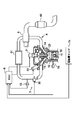
図1は、本発明に係る燃料噴射制御装置を含むディーゼルエンジンの概略構成図である。このディーゼルエンジンは多気筒式であって、燃料である軽油を高圧貯蔵するコモンレール21に接続されている燃料インジェクタ23により燃焼室12内に直接燃料を噴射して着火燃焼させることでシリンダ10内のピストン11を往復駆動するものである。燃焼室12には吸気弁13、排気弁14を介してそれぞれ吸気管3、排気管4が接続されており、排気のエネルギーにより吸気を促進するターボチャージャー5を備えている。ターボチャージャー5下流の吸気弁13との間の吸気管3内には、吸気を冷却するインタークーラー31、吸気絞り弁32、燃料インジェクタ22が配置される。この燃料インジェクタ22は、筒内の燃料インジェクタ23と同様にコモンレール21に接続される。排気管4のターボチャージャー5下流には、DPNR(Diesel Particulate−NOx Reduction system)触媒等からなる排気浄化装置40が配置される。
【0020】
エンジンの作動を制御するECU6には、回転数センサ71、冷却水温センサ72、吸気温センサ73の各出力が入力され、燃料インジェクタ22、23、吸気絞り弁32の作動を制御する。このECU6が本発明に係る燃料噴射制御装置の制御部を構成する。
【0021】
このディーゼルエンジンにおいては、燃料インジェクタ23による筒内燃料噴射と、燃料インジェクタ22による吸気管噴射を組み合わせた燃料供給を行うことを特徴とする。
【0022】
燃料インジェクタ23を利用した燃料噴射としては、ピストン11の圧縮上死点到達時近傍で燃料を噴射するメイン噴射と、これに先立って、例えば圧縮行程または吸気行程において燃料を1度ないし複数回噴射するパイロット噴射がある。このパイロット噴射では、燃料の一部予混合化により、NOx、燃焼騒音低下という効果が得られるが、噴射量が増大するとボアフラッシングの危険性が増大する。
【0023】
吸気管噴射では、パイロット噴射と同様に燃料の一部予混合化を促すことができ、同様の効果が期待される。図2は燃料予混合割合(全燃料噴射量に対する吸気管噴射量の比率)と燃焼室12から排出されるスモークの量の関係を示すグラフであり、図3は、燃料予混合割合とトルクの関係を示すグラフである。これらの図から明らかなように、吸気管3内で燃料を噴射することで吸気管3内で予混合を促進して燃焼室12内に導入することにより、スモーク低減、出力増加が実現できる。これはボアフラッシングが抑制されるためであり、騒音を低減する効果もある。
【0024】
ただし、ディーゼルエンジンにおいて使用される軽油は揮発性が低く、低吸気温、低水温条件下では吸気管3の壁面への付着が起こりやすくなる。図4は、壁面への付着割合と、吸気管噴射量、吸気温・水温との関係を示すグラフである。吸気管噴射量が少ないと壁面への付着割合は増大する。吸気管噴射量が多くなると、燃料噴射による吸気の攪乱・混合効果が増大し、燃料と吸気の混合が促進されるためである。
【0025】
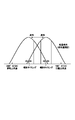
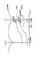
このように、燃料と吸気の混合を促進するためには、吸気弁13が十分に開いて吸気管3内の空気流の流速が十分に速い状態で燃料インジェクタ22からの燃料噴射を行う必要がある。噴射タイミングがずれて空気流の流速が遅い状態で燃料インジェクタ22からの燃料噴射を行うと、燃料が空気流に乗って燃焼室12内へ流入せず、大部分が吸気管3の壁面や吸気弁13の傘部等に付着してしまう。具体的には、吸気弁のリフト頂角の±30°CA域内で燃料噴射を行うことが好ましい。吸気弁13のリフトタイミングを可変としたVVTエンジンの場合には、図5に示されるようにリフトタイミングの変更(ここでは、低温時には吸気弁13のリフトタイミングを遅角側に補正する場合を例に示している。)に応じて噴射タイミングを変更する必要がある。図6はこのタイミング調整のフローチャートである。
【0026】
ステップS1では、エンジン回転数NeとQfinを読み込む。そして、ステップS2ではVVTの作動設定を行う。具体的には、指令バルブリフトタイミングTaを設定する。この指令バルブリフトタイミングTaとは、例えば、バルブリフトの頂点位置の角度である。続く、ステップS3、S4では、実バルブタイミングTfと指令バルブリフトタイミングTaとの偏差の絶対値を所定値と比較する。まず、ステップS3では、|Tf−Ta|が60°CA未満か以上かを判定する。|Tf−Ta|が60°CA以上の場合には、指令量と実際との偏差が過大であり、VVT機構が正常に機能していない可能性があるとしてステップS10へと移行し吸気管噴射中止を決定して処理を終了する。|Tf−Ta|が60°CA未満の場合には、ステップS4へと移行して|Tf−Ta|が2°CA未満か以上かを判定する。|Tf−Ta|が2°CA未満の場合には、TfとTaがほぼ一致し、後述する噴射タイミングの補正処理も完了しているとして処理を終了する。一方、|Tf−Ta|が2°CA以上60°CA未満の場合には、ステップS5へと移行してカウンタiを1加算する。このカウンタiはステップS1、S2時点では初期値0に設定されている。
【0027】
ステップS6ではカウンタiの値が10未満であるか否かを判定する。10以上の場合には、後述の補正処理の処理回数が設定条件を超えていると判定してステップS10へと移行し、吸気管噴射を中止して処理を終了する。10未満の場合には、ステップS7移行の噴射タイミング補正処理に移行する。
【0028】
ステップS7では、TfとTaの大小関係を判定する。Tfが大きい、つまり実際には進角側にずれている場合にはステップS8へと移行し、噴射タイミングTvをTaから求められるTvに対してTf−Taだけずらし(進角側)、Taを1°進角側にずらす。一方、Tfが小さい、つまり遅角側にずれている場合にはステップS9へと移行し、噴射タイミングTvをTaから求められるTvに対してTf−Taだけずらし(遅角側)、Taを1°遅角側にずらす。
【0029】
このように制御することで、バルブリフトタイミングや噴射タイミングの急変を抑制しつつ、噴射タイミングをバルブリフトタイミングに合わせて変更するので、最適な時期に吸気管噴射を行うことができ、壁面付着を効果的に抑制できる。
【0030】
また、表1はメイン噴射量Qmに対して吸気管噴射量Qvを変更した場合に、吸気管噴射量Qvのうち燃焼室12内で燃焼に用いられる量を示している。
【0031】
【表1】
【0032】
表よりわかるように、メイン噴射量Qmが少ないと、吸気管噴射量Qvのうち燃焼室12内で燃焼に用いられる量は減ってしまう。これは、メイン噴射量Qmが少ないと、燃焼開始が遅れ、燃焼室全体に火炎が行き渡らず、予混合気の中に燃え残りが発生するためである。
【0033】
そこで、本発明においては、比較的低負荷・低回転時にはパイロット噴射を優先し、高負荷・高回転時には、吸気管噴射に切り替える制御を行う。図7、図8は、この切替の制御マップの例を示す線図であり、図7が暖機後の常温時のマップを、図8が低水温・低吸気温(含冷間始動)時を示している。ここでは、2種類のマップを切り替える場合を例に説明するが、3種類以上のマップを吸気温やエンジン冷却水温に応じて切り替えてもよい。
【0034】
このように低回転・低負荷時(図中の領域(a))ではパイロット噴射を行い、高回転または高負荷時(図中の領域(c))では吸気管噴射を行い、中間領域となる領域(b)ではパイロット噴射と吸気管噴射の両方を実行することで、燃料の予混合化によるスモーク低減、トルク向上、NOx低減といった効果を全運転領域で得られるとともに、ボアフラッシングや吸気管3壁面への燃料付着を効果的に抑制することができる。
【0035】
ここで、吸気管噴射の噴射量算定に当たっては、壁面への付着および付着した燃料の脱離を推定して噴射量を算出する。また、実際にトルクとして用いられる燃料量を考慮して噴射を行う必要がある。一方、吸気管噴射量が増大するにつれて、オイル希釈が発生するおそれがある。オイル希釈はHC排出量の増加を伴うが、HC排出量の増加は排気浄化装置40の触媒温度の上昇から推定可能である。そこで、触媒温度が閾値を超えたらHC排出量が過大となり、オイル希釈の可能性大と判定し、吸気管噴射量Qvを減らしてその分だけメイン噴射量Qmを増大させるとともに、メイン噴射時期を進角させることで、吸気管噴射量Qv減少に伴うスモーク排出増大とトルク減少を抑制する。
【0036】
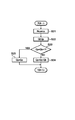
一方、図中の領域(b)(c)から領域(a)へ制御が切り替わった場合には、吸気管噴射中の壁面への付着を考慮してパイロット噴射量を調整する必要がある。図9にその制御フローを示す。
【0037】
ステップS21では、回転数センサ71の出力からエンジン回転数Neを読み込むとともに、図示していないアクセル開度センサの出力をもとにアクセル開度accpを検出する。続く、ステップS22では、燃料噴射量Qf、このうちのパイロット燃料噴射量Qpを算出する。ステップS23では、Qpを前回の運転サイクルにおける吸気管噴射量Qbと比較する。QpがQb+1より小さい場合には、パイロット噴射量Qpが少ない軽負荷時であると判定する。このような軽負荷時においては、壁面付着燃料が全て脱離して筒内に流入した場合であってもそれが気化せず、燃焼に寄与しない可能性がある。この場合に付着燃料の脱離を考慮してパイロット噴射量を抑制すると、燃焼騒音やNOx排出量が急増してしまう。そこでこのような場合にはステップS25へと移行して、パイロット噴射量Qpをそのまま維持する。反対に、QpがQb+1以上の場合には、このような問題の起こる軽負荷領域ではないと判定し、ステップS24へと移行して、付着燃料の脱離を考慮してパイロット噴射量Qpを脱離量Qbだけ減少させる。
【0038】
本実施形態ではさらに、燃焼室12内の燃料・混合気の着火時期は、メイン噴射の時期によってコントロールする。メイン噴射時期が遅すぎたり、メイン噴射量が少なすぎる場合、吸気管噴射やパイロット噴射によって生成された混合気が自己着火してしまい、予期せぬ急激な燃焼を発生させて騒音の発生、ひいてはエンジンの損傷のおそれがある。そこで、メイン噴射量、吸気管噴射量に応じてメイン噴射時期の遅角側限界値を設定し、これより進角側に制御することでメイン噴射前の自着火発生を抑制する。表2はその限界値設定の一例を示すものであり、メイン噴射量が同一なら吸気管噴射量が多いほど、吸気管噴射量が同一ならメイン噴射量が少ないほど進角側に遅角側限界値を設定する。
【0039】
【表2】
【0040】
本実施形態の燃料噴射制御においては、コモンレール式噴射系21が各気筒でパイロット噴射とメイン噴射で1行程に複数回の燃料噴射を行うため、他の気筒と噴射指令時期の干渉が起こる。相互干渉が大きくなると、燃料噴射に用いられるインジェクタの作動を制御するEDU(図示せず)のチャージが十分でない状態で噴射指令が発生し、燃料噴射が不十分であったり、噴射されない場合が出て、トルク変動の要因となる。また、トータル噴射量をもとに管理しているEGR(排ガス再循環)、ターボチャージャー5、吸気絞り弁32の作動制御の実際とのずれが大きくなってしまう。そこで、相互干渉を抑制するため、燃料噴射に優先順位をつけ、優先下位の噴射時期を遅らせることでEDUチャージ不足による無噴射とこれに伴うトルク変動、エミッション悪化を抑制する。
【0041】
EDUのチャージ不足を判定した場合は、複数の噴射指令の有無を判別し、噴射指令が複数ある場合には、(1)メイン噴射、(2)ポスト噴射(メイン噴射後の燃料噴射)、(3)多段噴射(含むパイロット噴射)、(4)吸気管噴射、(5)触媒用ポスト噴射、の順で優先順位を設定し、優先下位の噴射時期を遅らせる。同一優先順位内で複数回の噴射が行われる場合には、メイン噴射に近い噴射を優先する。
【0042】
前述したように、メイン噴射量Qmが少ないと、吸気管噴射量Qvのうち燃焼に寄与せずHCとして排出される量が増大する。これを利用して吸気管噴射量Qvを増大させてHC、COの排出量を増大させることにより、排気浄化装置40で急増したNOxを還元することができる。吸気管噴射量Qvは中負荷領域でも増大させることができ、噴射量増大に伴うスモークの発生を抑制できるため、NOx還元が可能な領域が拡大する。そのため、排気浄化触媒が吸蔵限界に到達するのを防止することができ、良好なエミッションを維持できる。
【0043】
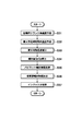
次に、始動時制御について説明する。始動時においては、フリクションに打ち勝つだけの十分な量の燃料を燃焼させ、低い筒内温度条件でも確実に着火させることが要求される。一方で、燃焼に寄与しない燃料の過剰噴射を抑制する必要があるため、着火条件を予測して適切な量の燃料を適切な時期に噴射する必要がある。図10はこの始動時制御のフローチャートであり、図11は、始動時制御におけるクランク角速度、筒内圧、筒内温度、噴射タイミングを示すタイミングチャートである。
【0044】
まず、ステップS31では、TDC前のクランク角速度をもとにして圧縮時の角速度を予測する。次のステップS32では、この角速度と水温、吸気温、吸気圧等から着火予定時期における筒内温度を予測する。ステップS33では、着火可能温度を筒内圧予測によって補正する。ステップS34では、着火可能温度と予想筒内温度との差から吸気管噴射量Qvと着火用のパイロット噴霧量Qpを設定する。ステップS35では、着火用のパイロット噴霧の噴射時期を予想筒内温度により補正した着火遅れにより求める。ステップS36では、吸気管噴射の噴射時期を筒内温度予測により補正する。この噴射は所定の着火時期より先に自己着火しない範囲でできるだけ速い時期に設定する。ステップS37では、こうして設定した噴射量、噴射タイミングに応じてコモンレール式噴射系21および燃料インジェクタ22により燃料噴射を実行する。
【0045】
このようにして噴射を行うことで、より少ない燃料で着火しやすい環境を形成することができ、着火させたい予定時期以前の自己着火が抑制されるので、始動性が向上する。
【0046】
【発明の効果】
以上説明したように本発明によれば、ディーゼルエンジンにおいて、メインの筒内噴射のほかに筒内へのパイロット噴射と吸気管噴射を組み合わせて、負荷・回転数に応じて適切な組み合わせを選択することにより、ボアフラッシングや吸気管壁面への燃料付着を抑制しつつ、予混合化によるスモーク低減、トルク向上、騒音低減、NOx低下等の効果が得られる。
【図面の簡単な説明】
【図1】本発明に係る燃料噴射制御装置を含むディーゼルエンジンの概略構成図である。
【図2】燃料予混合割合と燃焼室から排出されるスモーク量の関係を示すグラフである。
【図3】燃料予混合割合とトルクの関係を示すグラフである。
【図4】壁面への付着割合と、吸気管噴射量、吸気温・水温との関係を示すグラフである。
【図5】VVTエンジンにおけるリフトタイミングと噴射タイミングの関係を示す図である。
【図6】燃料噴射タイミング調整のフローチャートである。
【図7】パイロット噴射と吸気管噴射の切替制御マップ(暖機後常温時)である。
【図8】パイロット噴射と吸気管噴射の切替制御マップ(低水温・低吸気温時)である。
【図9】壁面への付着を考慮したパイロット噴射量調整の制御フローである。
【図10】始動時制御のフローチャートである。
【図11】始動時制御のタイミングチャートである。
【符号の説明】
3…吸気管、4…排気管、5…ターボチャージャー、6…ECU、10…シリンダ、11…ピストン、12…燃焼室、13…吸気弁、14…排気弁、21…コモンレール、22、23…燃料インジェクタ、31…インタークーラー、32…吸気絞り弁、40…排気浄化装置、71…回転数センサ、72…冷却水温センサ、73…吸気温センサ。[0001]
TECHNICAL FIELD OF THE INVENTION
The present invention relates to a fuel injection control device that controls fuel injection of a diesel engine including a device that injects fuel into a cylinder and an intake pipe.
[0002]
[Prior art]
In a diesel engine, the air taken into a cylinder (cylinder) is heated to a high temperature by high compression, and fuel is injected into the air to spontaneously ignite and explosively burn to obtain an output.
[0003]
Diesel engines can use light oil, which is less volatile than gasoline, as fuel, and are widely used in buses, trucks, and the like as highly economical engines because of their low cost and good thermal efficiency. On the other hand, diesel engines emit a greater amount of suspended particulate matter (SPM) and NOx composed of unburned fuel than gasoline engines, and in recent years, regulations have been tightened as substances causing air pollution. There is a need for reduction measures.
[0004]
SPM generation in a diesel engine is remarkable in a high-load and high-speed region where it is necessary to shorten the fuel injection time into the cylinder.
[0005]
As means for suppressing the generation of SPM, auxiliary fuel is also injected into the intake pipe to reduce the amount of fuel injected into the cylinder and shorten the fuel injection time into the cylinder, thereby igniting the fuel. Techniques for suppressing combustion delay are known.
[0006]
[Problems to be solved by the invention]
However, light oil is less volatile than gasoline, so it is difficult to vaporize by direct injection into the intake pipe, and if introduced into the cylinder without vaporization, it may not contribute to combustion, but rather degrade emissions. is there.
[0007]
As a countermeasure, there is a method of using a low-boiling fuel such as gasoline as an auxiliary fuel, or separating light oil into a high-boiling component and a low-boiling component and using the low-boiling component as the auxiliary fuel, but the fuel supply system is complicated. And there is a problem that the trouble of refueling increases.
[0008]
In addition, a technology called a HCCI (Homogeneous-Charge Compression Ignition Combustion) engine that guides a lean air-fuel mixture into a cylinder and burns by self-ignition has attracted attention. : Exhaust gas recirculation), it is difficult to control the ignition timing, and the fluctuation range of the load / rotational speed is narrow.
[0009]
Therefore, an object of the present invention is to provide a fuel injection control device for a diesel engine that uses the same auxiliary fuel and main fuel, can easily control ignition timing, and can suppress generation of SPM.
[0010]
[Means for Solving the Problems]
In order to solve the above-mentioned problems, a fuel injection control device according to the present invention includes a fuel supply device for in-cylinder fuel injection for injecting fuel into a cylinder of a diesel engine and a fuel supply device for in-pipe fuel injection for injecting fuel into an intake pipe. In addition to the main injection performed by the in-cylinder fuel injector near the top dead center of the compression stroke, the in-cylinder fuel injector controls the main injection in the low rotational speed and low load region prior to the main injection. Or multiple pilot injections, the intake pipe injection is executed by the fuel injection device in the intake pipe in the high rotation or high load range, and both the pilot injection and the intake pipe injection are performed in the middle range between the two. And
[0011]
Premixed air is formed in the cylinder before the main injection by the pilot injection or the intake pipe injection, and the main injection amount can be reduced. Therefore, ignition and combustion delays are suppressed to reduce NOx, reduce combustion noise, and suppress SPM. Can be achieved. In the low-load and low-speed range where it is difficult to atomize fuel in the intake pipe, pilot injection forms a premixed mixture, making it difficult to increase the injection time and mixing time of pilot injection. By performing the intake pipe injection in a high rotation speed and high load region where there is a possibility of bore flushing, it is possible to form a reliable premixed gas.
[0012]
The lower the engine cooling water temperature or intake air temperature, the greater the risk of fuel injected into the intake pipe adhering to the intake port without vaporization, so the pilot injection execution area should be expanded toward the high rotation / high load area. Therefore, it is preferable to narrow the region of the intake pipe injection.
[0013]
At the time of transition from high load or high speed range to low load and low speed range, control the pilot injection amount in consideration of the amount of fuel desorbed from the wall and control the decrease in the injection amount. Is preferred. At the time of such a transition, it is necessary to perform correction control to reduce the fuel amount of the pilot injection by the amount of fuel that adheres to the wall surface, desorbs and flows into the cylinder by the previous cycle. This is because there is a possibility that the desorbed fuel does not contribute to the combustion, and thus it is necessary to secure a fuel amount of the pilot fuel in order to continue the normal combustion.
[0014]
It is preferable to control the timing of the injection of the intake pipe in accordance with the timing when the intake valve is close to full open. In this case, the fuel can be injected into the flowing intake air, so that atomization can be promoted.
[0015]
This diesel engine has a plurality of cylinders, and gives top priority to the main injection by the in-cylinder fuel injection system in the calculation of injection quantity and injection timing control, and the lower the other fuel injections are, the further the position and time are separated from this. It is preferable to control with priority.
[0016]
In the case of a multi-cylinder, a fuel injection command to a certain cylinder and a fuel injection command to another cylinder may overlap with each other in time, and may interfere with each other. As a result of this interference, if the fuel supply is not sufficient, torque fluctuations due to insufficient fuel and deterioration of exhaust performance are caused. Therefore, by giving priority to the main injection at the time of various correction controls, and giving priority to the injection that is close in position and time, correction of the injection between cylinders is avoided, and torque fluctuation and exhaust performance Suppress deterioration.
[0017]
It is preferable to control the injection timing of the pilot injection and the intake pipe injection based on the predicted in-cylinder temperature. By predicting the ignition conditions and controlling the injection timing, it is possible to reliably ignite with a small amount of fuel even if the in-cylinder temperature is low, and the startability at low temperatures is improved.
[0018]
BEST MODE FOR CARRYING OUT THE INVENTION
Hereinafter, preferred embodiments of the present invention will be described in detail with reference to the accompanying drawings. In order to facilitate understanding of the description, the same components are denoted by the same reference numerals as much as possible in each drawing, and redundant description is omitted.
[0019]
FIG. 1 is a schematic configuration diagram of a diesel engine including a fuel injection control device according to the present invention. This diesel engine is a multi-cylinder type, and injects fuel directly into the combustion chamber 12 by a fuel injector 23 connected to a common rail 21 that stores light oil as fuel at high pressure, and ignites and burns the fuel in the cylinder 10. The piston 11 is driven reciprocally. An intake pipe 3 and an exhaust pipe 4 are connected to the combustion chamber 12 via an intake valve 13 and an exhaust valve 14, respectively. The combustion chamber 12 is provided with a turbocharger 5 for promoting intake by energy of exhaust. In the intake pipe 3 between the intake valve 13 downstream of the turbocharger 5, an intercooler 31 for cooling intake air, an intake throttle valve 32, and a fuel injector 22 are arranged. This fuel injector 22 is connected to the common rail 21 similarly to the fuel injector 23 in the cylinder. Downstream of the turbocharger 5 of the exhaust pipe 4, an exhaust gas purification device 40 including a DPNR (Diesel Particulate-NOx Reduction system) catalyst or the like is arranged.
[0020]
The outputs of the rotation speed sensor 71, the coolant temperature sensor 72, and the intake temperature sensor 73 are input to the ECU 6 that controls the operation of the engine, and controls the operation of the fuel injectors 22, 23 and the intake throttle valve 32. The ECU 6 constitutes a control unit of the fuel injection control device according to the present invention.
[0021]
This diesel engine is characterized by performing fuel supply by combining in-cylinder fuel injection by the fuel injector 23 and intake pipe injection by the fuel injector 22.
[0022]
The fuel injection using the fuel injector 23 includes main injection for injecting fuel near the time when the piston 11 reaches the compression top dead center, and prior to this, fuel is injected one or more times in, for example, a compression stroke or an intake stroke. There is a pilot injection to do. In this pilot injection, the effect of lowering NOx and combustion noise is obtained by partially premixing the fuel, but the risk of bore flushing increases as the injection amount increases.
[0023]
In the intake pipe injection, similar to the pilot injection, partial premixing of fuel can be promoted, and the same effect is expected. FIG. 2 is a graph showing the relationship between the fuel premix ratio (the ratio of the intake pipe injection amount to the total fuel injection amount) and the amount of smoke discharged from the combustion chamber 12. FIG. 3 is a graph showing the relationship between the fuel premix ratio and the torque. It is a graph which shows a relationship. As is apparent from these drawings, by injecting fuel in the intake pipe 3 to promote premixing in the intake pipe 3 and introducing the fuel into the combustion chamber 12, smoke reduction and output increase can be realized. This is because bore flushing is suppressed, and there is also an effect of reducing noise.
[0024]
However, light oil used in a diesel engine has low volatility, and easily adheres to the wall surface of the intake pipe 3 under low intake air temperature and low water temperature conditions. FIG. 4 is a graph showing the relationship between the adhesion ratio to the wall surface, the intake pipe injection amount, and the intake air temperature / water temperature. When the injection amount of the intake pipe is small, the adhesion ratio to the wall surface increases. This is because, when the intake pipe injection amount increases, the effect of disturbing and mixing the intake air by the fuel injection increases, and the mixing of the fuel and the intake air is promoted.
[0025]
As described above, in order to promote the mixing of the fuel and the intake air, it is necessary to perform the fuel injection from the fuel injector 22 in a state where the intake valve 13 is sufficiently opened and the flow velocity of the air flow in the intake pipe 3 is sufficiently fast. is there. When the fuel is injected from the fuel injector 22 in a state where the injection timing is shifted and the airflow velocity is low, the fuel does not flow into the combustion chamber 12 due to the airflow, and most of the fuel does not flow into the wall of the intake pipe 3 or the intake air. It adheres to the umbrella portion of the valve 13 and the like. Specifically, it is preferable to perform the fuel injection within a range of ± 30 ° CA of the lift apex angle of the intake valve. In the case of a VVT engine in which the lift timing of the intake valve 13 is made variable, the lift timing is changed as shown in FIG. 5 (here, an example in which the lift timing of the intake valve 13 is corrected to the retard side at low temperatures). It is necessary to change the injection timing according to the above. FIG. 6 is a flowchart of the timing adjustment.
[0026]
In step S1, the engine speed Ne and Qfin are read. Then, in step S2, the operation setting of the VVT is performed. Specifically, the command valve lift timing Ta is set. The command valve lift timing Ta is, for example, the angle of the peak position of the valve lift. In steps S3 and S4, the absolute value of the deviation between the actual valve timing Tf and the command valve lift timing Ta is compared with a predetermined value. First, in step S3, it is determined whether | Tf−Ta | is less than or equal to 60 ° CA. If | Tf−Ta | is equal to or greater than 60 ° CA, it is determined that the deviation between the command amount and the actual value is excessive, and the VVT mechanism may not be functioning properly. The cancellation is determined and the process ends. If | Tf−Ta | is less than 60 ° CA, the process proceeds to step S4 to determine whether | Tf−Ta | is less than or equal to 2 ° CA. If | Tf−Ta | is less than 2 ° CA, Tf and Ta substantially match, and the process ends, assuming that the injection timing correction process described later has also been completed. On the other hand, when | Tf−Ta | is equal to or greater than 2 ° CA and less than 60 ° CA, the process proceeds to step S5 and the counter i is incremented by one. This counter i is set to the initial value 0 at the time of steps S1 and S2.
[0027]
In step S6, it is determined whether or not the value of the counter i is less than 10. If the number is equal to or greater than 10, it is determined that the number of times of the correction process described below exceeds the set condition, and the process shifts to step S10 to stop the intake pipe injection and terminate the process. If it is less than 10, the process proceeds to the injection timing correction process of step S7.
[0028]
In step S7, the magnitude relationship between Tf and Ta is determined. When Tf is large, that is, when it is actually shifted to the advance side, the process proceeds to step S8, and the injection timing Tv is shifted by Tf-Ta with respect to Tv obtained from Ta (advance side), and Ta is set. Shift to the 1 ° advance side. On the other hand, when Tf is small, that is, when it is shifted to the retard side, the process proceeds to step S9, the injection timing Tv is shifted by Tf-Ta with respect to Tv obtained from Ta (retard side), and Ta is set to 1 ° Shift to the retard side.
[0029]
By controlling in this way, the injection timing is changed in accordance with the valve lift timing while suppressing a sudden change in the valve lift timing and the injection timing. It can be suppressed effectively.
[0030]
Table 1 shows the amount of the intake pipe injection amount Qv used for combustion in the combustion chamber 12 when the intake pipe injection amount Qv is changed with respect to the main injection amount Qm.
[0031]
[Table 1]
[0032]
As can be seen from the table, when the main injection amount Qm is small, the amount of the intake pipe injection amount Qv used for combustion in the combustion chamber 12 is reduced. This is because if the main injection amount Qm is small, the start of combustion is delayed, the flame does not reach the entire combustion chamber, and the unburned gas remains in the premixed gas.
[0033]
Therefore, in the present invention, control is performed such that pilot injection is prioritized at a relatively low load / low rotation, and switching to intake pipe injection is performed at a high load / high rotation. FIGS. 7 and 8 are diagrams showing examples of the control map for this switching. FIG. 7 shows a map at normal temperature after warm-up, and FIG. 8 shows a map at low water temperature / low intake air temperature (starting during cold operation). Is shown. Here, a case where two types of maps are switched will be described as an example, but three or more types of maps may be switched according to the intake air temperature or the engine cooling water temperature.
[0034]
As described above, pilot injection is performed during low rotation and low load (region (a) in the drawing), and intake pipe injection is performed during high rotation or high load (region (c) in the drawing), resulting in an intermediate region. By performing both pilot injection and intake pipe injection in the area (b), effects such as smoke reduction, torque improvement, and NOx reduction by premixing of fuel can be obtained in all operation areas, and bore flushing and intake pipe 3 Fuel adhesion to the wall surface can be effectively suppressed.
[0035]
Here, in calculating the injection amount of the intake pipe injection, the injection amount is calculated by estimating the adhesion to the wall surface and the desorption of the attached fuel. Further, it is necessary to perform the injection in consideration of the fuel amount actually used as the torque. On the other hand, as the intake pipe injection amount increases, oil dilution may occur. Oil dilution involves an increase in the amount of HC emission, but the increase in the amount of HC emission can be estimated from an increase in the catalyst temperature of the exhaust gas purification device 40. Therefore, when the catalyst temperature exceeds the threshold value, the HC discharge amount becomes excessive, it is determined that the possibility of oil dilution is large, the intake pipe injection amount Qv is reduced, the main injection amount Qm is increased by that amount, and the main injection timing is adjusted. The advanced angle suppresses an increase in smoke emission and a decrease in torque due to a decrease in the intake pipe injection amount Qv.
[0036]
On the other hand, when the control is switched from the areas (b) and (c) in the figure to the area (a), it is necessary to adjust the pilot injection amount in consideration of the adhesion to the wall surface during the intake pipe injection. FIG. 9 shows the control flow.
[0037]
In step S21, the engine speed Ne is read from the output of the speed sensor 71, and the accelerator opening accp is detected based on the output of an accelerator opening sensor (not shown). In the following step S22, the fuel injection amount Qf and the pilot fuel injection amount Qp among them are calculated. In step S23, Qp is compared with the intake pipe injection amount Qb in the previous operation cycle. If Qp is smaller than Qb + 1, it is determined that the pilot injection amount Qp is small and the load is light. At the time of such a light load, even when all the fuel adhered to the wall surface is desorbed and flows into the cylinder, the fuel does not vaporize and may not contribute to combustion. In this case, if the pilot injection amount is suppressed in consideration of the detachment of the attached fuel, the combustion noise and the NOx emission amount increase rapidly. Therefore, in such a case, the process proceeds to step S25, and the pilot injection amount Qp is maintained as it is. On the other hand, when Qp is equal to or larger than Qb + 1, it is determined that the region is not the light load region in which such a problem occurs, and the process shifts to step S24 to reduce the pilot injection amount Qp in consideration of the detachment of the attached fuel. It is decreased by the separation amount Qb.
[0038]
Further, in the present embodiment, the ignition timing of the fuel / air-fuel mixture in the combustion chamber 12 is controlled by the timing of the main injection. If the main injection timing is too late or the main injection amount is too small, the air-fuel mixture generated by the intake pipe injection or pilot injection will self-ignite, generating unexpected sudden combustion and generating noise, and eventually noise. The engine may be damaged. Therefore, a retarded limit value of the main injection timing is set in accordance with the main injection amount and the intake pipe injection amount, and the ignition timing is controlled to be more advanced to suppress the occurrence of self-ignition before the main injection. Table 2 shows an example of the limit value setting. If the main injection amount is the same, the larger the intake pipe injection amount, the smaller the main injection amount if the intake pipe injection amount is the same. Set the value.
[0039]
[Table 2]
[0040]
In the fuel injection control of the present embodiment, since the common rail injection system 21 performs the fuel injection in each cylinder a plurality of times in one stroke between the pilot injection and the main injection, interference occurs between the other cylinders and the injection command timing. When the mutual interference increases, an injection command is issued in a state where the charge of an EDU (not shown) for controlling the operation of the injector used for fuel injection is not sufficient, and the fuel injection may be insufficient or may not be performed. Therefore, it becomes a factor of torque fluctuation. Further, deviations from actual control of the operation of the EGR (exhaust gas recirculation), the turbocharger 5, and the intake throttle valve 32, which are managed based on the total injection amount, increase. Therefore, in order to suppress the mutual interference, the fuel injection is prioritized, and the lower priority injection timing is delayed, thereby suppressing no injection due to insufficient EDU charge, and accompanying torque fluctuation and emission deterioration.
[0041]
When it is determined that the EDU is insufficiently charged, it is determined whether there are a plurality of injection commands. When there are a plurality of injection commands, (1) main injection, (2) post injection (fuel injection after main injection), ( The priority order is set in the order of 3) multi-stage injection (including pilot injection), (4) intake pipe injection, and (5) catalyst post injection, and the lower priority injection timing is delayed. When multiple injections are performed within the same priority, priority is given to the injection close to the main injection.
[0042]
As described above, when the main injection amount Qm is small, the amount of HC exhausted as HC without contributing to combustion increases. By utilizing this, the intake pipe injection amount Qv is increased to increase the emission amount of HC and CO, so that the NOx that has rapidly increased in the exhaust purification device 40 can be reduced. The intake pipe injection amount Qv can be increased even in the medium load region, and the generation of smoke accompanying the increase in the injection amount can be suppressed, so that the region where NOx can be reduced is expanded. Therefore, it is possible to prevent the exhaust purification catalyst from reaching the storage limit, and to maintain good emission.
[0043]
Next, the starting control will be described. At the time of start-up, it is required to burn a sufficient amount of fuel to overcome friction and to reliably ignite even under low in-cylinder temperature conditions. On the other hand, since it is necessary to suppress excessive injection of fuel that does not contribute to combustion, it is necessary to predict an ignition condition and inject an appropriate amount of fuel at an appropriate time. FIG. 10 is a flowchart of the starting control, and FIG. 11 is a timing chart showing the crank angular velocity, the in-cylinder pressure, the in-cylinder temperature, and the injection timing in the starting control.
[0044]
First, in step S31, the angular velocity at the time of compression is predicted based on the crank angular velocity before TDC. In the next step S32, the cylinder temperature at the scheduled ignition timing is predicted from the angular velocity, the water temperature, the intake air temperature, the intake pressure and the like. In step S33, the ignitable temperature is corrected by predicting the in-cylinder pressure. In step S34, the intake pipe injection amount Qv and the ignition pilot spray amount Qp are set from the difference between the ignitable temperature and the predicted in-cylinder temperature. In step S35, the injection timing of the ignition pilot spray is obtained from the ignition delay corrected based on the estimated in-cylinder temperature. In step S36, the injection timing of the intake pipe injection is corrected by in-cylinder temperature prediction. This injection is set as early as possible within a range that does not self-ignite before a predetermined ignition timing. In step S37, fuel injection is performed by the common rail injection system 21 and the fuel injector 22 according to the injection amount and the injection timing thus set.
[0045]
By performing the injection in this manner, an environment in which ignition is easy with less fuel can be formed, and self-ignition before the scheduled time at which ignition is desired is suppressed, so that startability is improved.
[0046]
【The invention's effect】
As described above, according to the present invention, in a diesel engine, in addition to main in-cylinder injection, pilot injection into the cylinder and intake pipe injection are combined, and an appropriate combination is selected according to the load and the number of revolutions. Thus, effects such as smoke reduction, torque improvement, noise reduction, and NOx reduction by premixing can be obtained while suppressing bore flushing and fuel adhesion to the intake pipe wall surface.
[Brief description of the drawings]
FIG. 1 is a schematic configuration diagram of a diesel engine including a fuel injection control device according to the present invention.
FIG. 2 is a graph showing a relationship between a fuel premix ratio and an amount of smoke discharged from a combustion chamber.
FIG. 3 is a graph showing a relationship between a fuel premix ratio and a torque.
FIG. 4 is a graph showing a relationship between a ratio of adhesion to a wall surface, an intake pipe injection amount, and intake air temperature / water temperature.
FIG. 5 is a diagram showing a relationship between a lift timing and an injection timing in a VVT engine.
FIG. 6 is a flowchart of fuel injection timing adjustment.
FIG. 7 is a control map for switching between pilot injection and intake pipe injection (at normal temperature after warm-up).
FIG. 8 is a switching control map for pilot injection and intake pipe injection (at low water temperature and low intake air temperature).
FIG. 9 is a control flow of pilot injection amount adjustment in consideration of adhesion to a wall surface.
FIG. 10 is a flowchart of start-time control.
FIG. 11 is a timing chart of start-up control.
[Explanation of symbols]
3 ... intake pipe, 4 ... exhaust pipe, 5 ... turbocharger, 6 ... ECU, 10 ... cylinder, 11 ... piston, 12 ... combustion chamber, 13 ... intake valve, 14 ... exhaust valve, 21 ... common rail, 22, 23 ... Fuel injector, 31 ... intercooler, 32 ... intake throttle valve, 40 ... exhaust gas purification device, 71 ... rotation speed sensor, 72 ... cooling water temperature sensor, 73 ... intake air temperature sensor.