JP6466609B2 - Centrifugal pump - Google Patents
Centrifugal pump Download PDFInfo
- Publication number
- JP6466609B2 JP6466609B2 JP2018042203A JP2018042203A JP6466609B2 JP 6466609 B2 JP6466609 B2 JP 6466609B2 JP 2018042203 A JP2018042203 A JP 2018042203A JP 2018042203 A JP2018042203 A JP 2018042203A JP 6466609 B2 JP6466609 B2 JP 6466609B2
- Authority
- JP
- Japan
- Prior art keywords
- blood
- inflow port
- bearing
- flow path
- centrifugal pump
- Prior art date
- Legal status (The legal status is an assumption and is not a legal conclusion. Google has not performed a legal analysis and makes no representation as to the accuracy of the status listed.)
- Active
Links
- 239000008280 blood Substances 0.000 claims description 175
- 210000004369 blood Anatomy 0.000 claims description 175
- 230000002093 peripheral effect Effects 0.000 claims description 56
- 230000017531 blood circulation Effects 0.000 claims description 48
- 238000011144 upstream manufacturing Methods 0.000 claims description 8
- 239000000463 material Substances 0.000 description 17
- 208000007536 Thrombosis Diseases 0.000 description 9
- 239000000470 constituent Substances 0.000 description 7
- 230000015572 biosynthetic process Effects 0.000 description 6
- 238000009434 installation Methods 0.000 description 6
- 239000007769 metal material Substances 0.000 description 6
- -1 polyethylene Polymers 0.000 description 6
- 239000000919 ceramic Substances 0.000 description 5
- 238000003780 insertion Methods 0.000 description 5
- 230000037431 insertion Effects 0.000 description 5
- 238000000034 method Methods 0.000 description 5
- 239000004698 Polyethylene Substances 0.000 description 4
- 230000004927 fusion Effects 0.000 description 4
- 229920000178 Acrylic resin Polymers 0.000 description 3
- 239000004925 Acrylic resin Substances 0.000 description 3
- 239000004721 Polyphenylene oxide Substances 0.000 description 3
- 229920003229 poly(methyl methacrylate) Polymers 0.000 description 3
- 229920000728 polyester Polymers 0.000 description 3
- 229920000573 polyethylene Polymers 0.000 description 3
- 239000004926 polymethyl methacrylate Substances 0.000 description 3
- 229920000098 polyolefin Polymers 0.000 description 3
- 239000011347 resin Substances 0.000 description 3
- 229920005989 resin Polymers 0.000 description 3
- 229920000572 Nylon 6/12 Polymers 0.000 description 2
- 239000004952 Polyamide Substances 0.000 description 2
- 239000004743 Polypropylene Substances 0.000 description 2
- PPBRXRYQALVLMV-UHFFFAOYSA-N Styrene Chemical compound C=CC1=CC=CC=C1 PPBRXRYQALVLMV-UHFFFAOYSA-N 0.000 description 2
- 239000004699 Ultra-high molecular weight polyethylene Substances 0.000 description 2
- 230000014759 maintenance of location Effects 0.000 description 2
- 238000000465 moulding Methods 0.000 description 2
- 229920001200 poly(ethylene-vinyl acetate) Polymers 0.000 description 2
- 229920002647 polyamide Polymers 0.000 description 2
- 229920001707 polybutylene terephthalate Polymers 0.000 description 2
- 239000004417 polycarbonate Substances 0.000 description 2
- 229920000515 polycarbonate Polymers 0.000 description 2
- 229920000570 polyether Polymers 0.000 description 2
- 239000004800 polyvinyl chloride Substances 0.000 description 2
- 229920000915 polyvinyl chloride Polymers 0.000 description 2
- 229920000785 ultra high molecular weight polyethylene Polymers 0.000 description 2
- OKTJSMMVPCPJKN-UHFFFAOYSA-N Carbon Chemical compound [C] OKTJSMMVPCPJKN-UHFFFAOYSA-N 0.000 description 1
- 239000004709 Chlorinated polyethylene Substances 0.000 description 1
- YCKRFDGAMUMZLT-UHFFFAOYSA-N Fluorine atom Chemical compound [F] YCKRFDGAMUMZLT-UHFFFAOYSA-N 0.000 description 1
- JHWNWJKBPDFINM-UHFFFAOYSA-N Laurolactam Chemical compound O=C1CCCCCCCCCCCN1 JHWNWJKBPDFINM-UHFFFAOYSA-N 0.000 description 1
- 229920000106 Liquid crystal polymer Polymers 0.000 description 1
- 239000004977 Liquid-crystal polymers (LCPs) Substances 0.000 description 1
- BGPVFRJUHWVFKM-UHFFFAOYSA-N N1=C2C=CC=CC2=[N+]([O-])C1(CC1)CCC21N=C1C=CC=CC1=[N+]2[O-] Chemical compound N1=C2C=CC=CC2=[N+]([O-])C1(CC1)CCC21N=C1C=CC=CC1=[N+]2[O-] BGPVFRJUHWVFKM-UHFFFAOYSA-N 0.000 description 1
- 239000004677 Nylon Substances 0.000 description 1
- 229920000571 Nylon 11 Polymers 0.000 description 1
- 229920000299 Nylon 12 Polymers 0.000 description 1
- 229920003189 Nylon 4,6 Polymers 0.000 description 1
- 229920002292 Nylon 6 Polymers 0.000 description 1
- 229920000305 Nylon 6,10 Polymers 0.000 description 1
- 229920002302 Nylon 6,6 Polymers 0.000 description 1
- 239000004696 Poly ether ether ketone Substances 0.000 description 1
- 229930182556 Polyacetal Natural products 0.000 description 1
- 239000005062 Polybutadiene Substances 0.000 description 1
- 239000004734 Polyphenylene sulfide Substances 0.000 description 1
- 239000004793 Polystyrene Substances 0.000 description 1
- RTAQQCXQSZGOHL-UHFFFAOYSA-N Titanium Chemical compound [Ti] RTAQQCXQSZGOHL-UHFFFAOYSA-N 0.000 description 1
- 239000000853 adhesive Substances 0.000 description 1
- 230000001070 adhesive effect Effects 0.000 description 1
- 239000000956 alloy Substances 0.000 description 1
- 229910045601 alloy Inorganic materials 0.000 description 1
- 125000003118 aryl group Chemical group 0.000 description 1
- 238000005452 bending Methods 0.000 description 1
- 229910052799 carbon Inorganic materials 0.000 description 1
- 229920001577 copolymer Polymers 0.000 description 1
- 230000003247 decreasing effect Effects 0.000 description 1
- 230000000694 effects Effects 0.000 description 1
- 229920001971 elastomer Polymers 0.000 description 1
- 239000005038 ethylene vinyl acetate Substances 0.000 description 1
- 229910052731 fluorine Inorganic materials 0.000 description 1
- 239000011737 fluorine Substances 0.000 description 1
- 239000000203 mixture Substances 0.000 description 1
- 229920001778 nylon Polymers 0.000 description 1
- 229920002492 poly(sulfone) Polymers 0.000 description 1
- 229920001230 polyarylate Polymers 0.000 description 1
- 229920002857 polybutadiene Polymers 0.000 description 1
- 229920005668 polycarbonate resin Polymers 0.000 description 1
- 239000004431 polycarbonate resin Substances 0.000 description 1
- 229920002530 polyetherether ketone Polymers 0.000 description 1
- 229920001195 polyisoprene Polymers 0.000 description 1
- 229920000642 polymer Polymers 0.000 description 1
- 229920006324 polyoxymethylene Polymers 0.000 description 1
- 229920006380 polyphenylene oxide Polymers 0.000 description 1
- 229920000069 polyphenylene sulfide Polymers 0.000 description 1
- 229920001155 polypropylene Polymers 0.000 description 1
- 229920005606 polypropylene copolymer Polymers 0.000 description 1
- 229920002223 polystyrene Polymers 0.000 description 1
- 239000004814 polyurethane Substances 0.000 description 1
- 229920002635 polyurethane Polymers 0.000 description 1
- 230000003014 reinforcing effect Effects 0.000 description 1
- 239000005060 rubber Substances 0.000 description 1
- 239000002904 solvent Substances 0.000 description 1
- 239000010935 stainless steel Substances 0.000 description 1
- 229910001220 stainless steel Inorganic materials 0.000 description 1
- KKEYFWRCBNTPAC-UHFFFAOYSA-L terephthalate(2-) Chemical compound [O-]C(=O)C1=CC=C(C([O-])=O)C=C1 KKEYFWRCBNTPAC-UHFFFAOYSA-L 0.000 description 1
- 229920002725 thermoplastic elastomer Polymers 0.000 description 1
- 229920006259 thermoplastic polyimide Polymers 0.000 description 1
- 239000010936 titanium Substances 0.000 description 1
- 229910052719 titanium Inorganic materials 0.000 description 1
Images


Classifications
-
- F—MECHANICAL ENGINEERING; LIGHTING; HEATING; WEAPONS; BLASTING
- F04—POSITIVE - DISPLACEMENT MACHINES FOR LIQUIDS; PUMPS FOR LIQUIDS OR ELASTIC FLUIDS
- F04D—NON-POSITIVE-DISPLACEMENT PUMPS
- F04D29/00—Details, component parts, or accessories
- F04D29/40—Casings; Connections of working fluid
- F04D29/42—Casings; Connections of working fluid for radial or helico-centrifugal pumps
- F04D29/426—Casings; Connections of working fluid for radial or helico-centrifugal pumps especially adapted for liquid pumps
- F04D29/4273—Casings; Connections of working fluid for radial or helico-centrifugal pumps especially adapted for liquid pumps suction eyes
-
- F—MECHANICAL ENGINEERING; LIGHTING; HEATING; WEAPONS; BLASTING
- F04—POSITIVE - DISPLACEMENT MACHINES FOR LIQUIDS; PUMPS FOR LIQUIDS OR ELASTIC FLUIDS
- F04D—NON-POSITIVE-DISPLACEMENT PUMPS
- F04D29/00—Details, component parts, or accessories
- F04D29/04—Shafts or bearings, or assemblies thereof
- F04D29/046—Bearings
- F04D29/0467—Spherical bearings
-
- A—HUMAN NECESSITIES
- A61—MEDICAL OR VETERINARY SCIENCE; HYGIENE
- A61M—DEVICES FOR INTRODUCING MEDIA INTO, OR ONTO, THE BODY; DEVICES FOR TRANSDUCING BODY MEDIA OR FOR TAKING MEDIA FROM THE BODY; DEVICES FOR PRODUCING OR ENDING SLEEP OR STUPOR
- A61M60/00—Blood pumps; Devices for mechanical circulatory actuation; Balloon pumps for circulatory assistance
- A61M60/20—Type thereof
- A61M60/205—Non-positive displacement blood pumps
- A61M60/216—Non-positive displacement blood pumps including a rotating member acting on the blood, e.g. impeller
- A61M60/226—Non-positive displacement blood pumps including a rotating member acting on the blood, e.g. impeller the blood flow through the rotating member having mainly radial components
- A61M60/232—Centrifugal pumps
-
- A—HUMAN NECESSITIES
- A61—MEDICAL OR VETERINARY SCIENCE; HYGIENE
- A61M—DEVICES FOR INTRODUCING MEDIA INTO, OR ONTO, THE BODY; DEVICES FOR TRANSDUCING BODY MEDIA OR FOR TAKING MEDIA FROM THE BODY; DEVICES FOR PRODUCING OR ENDING SLEEP OR STUPOR
- A61M60/00—Blood pumps; Devices for mechanical circulatory actuation; Balloon pumps for circulatory assistance
- A61M60/40—Details relating to driving
- A61M60/403—Details relating to driving for non-positive displacement blood pumps
- A61M60/419—Details relating to driving for non-positive displacement blood pumps the force acting on the blood contacting member being permanent magnetic, e.g. from a rotating magnetic coupling between driving and driven magnets
-
- A—HUMAN NECESSITIES
- A61—MEDICAL OR VETERINARY SCIENCE; HYGIENE
- A61M—DEVICES FOR INTRODUCING MEDIA INTO, OR ONTO, THE BODY; DEVICES FOR TRANSDUCING BODY MEDIA OR FOR TAKING MEDIA FROM THE BODY; DEVICES FOR PRODUCING OR ENDING SLEEP OR STUPOR
- A61M60/00—Blood pumps; Devices for mechanical circulatory actuation; Balloon pumps for circulatory assistance
- A61M60/80—Constructional details other than related to driving
- A61M60/802—Constructional details other than related to driving of non-positive displacement blood pumps
- A61M60/804—Impellers
- A61M60/806—Vanes or blades
-
- A—HUMAN NECESSITIES
- A61—MEDICAL OR VETERINARY SCIENCE; HYGIENE
- A61M—DEVICES FOR INTRODUCING MEDIA INTO, OR ONTO, THE BODY; DEVICES FOR TRANSDUCING BODY MEDIA OR FOR TAKING MEDIA FROM THE BODY; DEVICES FOR PRODUCING OR ENDING SLEEP OR STUPOR
- A61M60/00—Blood pumps; Devices for mechanical circulatory actuation; Balloon pumps for circulatory assistance
- A61M60/80—Constructional details other than related to driving
- A61M60/802—Constructional details other than related to driving of non-positive displacement blood pumps
- A61M60/81—Pump housings
-
- A—HUMAN NECESSITIES
- A61—MEDICAL OR VETERINARY SCIENCE; HYGIENE
- A61M—DEVICES FOR INTRODUCING MEDIA INTO, OR ONTO, THE BODY; DEVICES FOR TRANSDUCING BODY MEDIA OR FOR TAKING MEDIA FROM THE BODY; DEVICES FOR PRODUCING OR ENDING SLEEP OR STUPOR
- A61M60/00—Blood pumps; Devices for mechanical circulatory actuation; Balloon pumps for circulatory assistance
- A61M60/80—Constructional details other than related to driving
- A61M60/802—Constructional details other than related to driving of non-positive displacement blood pumps
- A61M60/818—Bearings
- A61M60/825—Contact bearings, e.g. ball-and-cup or pivot bearings
-
- F—MECHANICAL ENGINEERING; LIGHTING; HEATING; WEAPONS; BLASTING
- F04—POSITIVE - DISPLACEMENT MACHINES FOR LIQUIDS; PUMPS FOR LIQUIDS OR ELASTIC FLUIDS
- F04D—NON-POSITIVE-DISPLACEMENT PUMPS
- F04D29/00—Details, component parts, or accessories
- F04D29/04—Shafts or bearings, or assemblies thereof
- F04D29/046—Bearings
-
- F—MECHANICAL ENGINEERING; LIGHTING; HEATING; WEAPONS; BLASTING
- F04—POSITIVE - DISPLACEMENT MACHINES FOR LIQUIDS; PUMPS FOR LIQUIDS OR ELASTIC FLUIDS
- F04D—NON-POSITIVE-DISPLACEMENT PUMPS
- F04D29/00—Details, component parts, or accessories
- F04D29/18—Rotors
- F04D29/22—Rotors specially for centrifugal pumps
-
- F—MECHANICAL ENGINEERING; LIGHTING; HEATING; WEAPONS; BLASTING
- F04—POSITIVE - DISPLACEMENT MACHINES FOR LIQUIDS; PUMPS FOR LIQUIDS OR ELASTIC FLUIDS
- F04D—NON-POSITIVE-DISPLACEMENT PUMPS
- F04D29/00—Details, component parts, or accessories
- F04D29/40—Casings; Connections of working fluid
- F04D29/42—Casings; Connections of working fluid for radial or helico-centrifugal pumps
- F04D29/426—Casings; Connections of working fluid for radial or helico-centrifugal pumps especially adapted for liquid pumps
- F04D29/4293—Details of fluid inlet or outlet
-
- A—HUMAN NECESSITIES
- A61—MEDICAL OR VETERINARY SCIENCE; HYGIENE
- A61M—DEVICES FOR INTRODUCING MEDIA INTO, OR ONTO, THE BODY; DEVICES FOR TRANSDUCING BODY MEDIA OR FOR TAKING MEDIA FROM THE BODY; DEVICES FOR PRODUCING OR ENDING SLEEP OR STUPOR
- A61M60/00—Blood pumps; Devices for mechanical circulatory actuation; Balloon pumps for circulatory assistance
- A61M60/10—Location thereof with respect to the patient's body
- A61M60/122—Implantable pumps or pumping devices, i.e. the blood being pumped inside the patient's body
- A61M60/126—Implantable pumps or pumping devices, i.e. the blood being pumped inside the patient's body implantable via, into, inside, in line, branching on, or around a blood vessel
- A61M60/148—Implantable pumps or pumping devices, i.e. the blood being pumped inside the patient's body implantable via, into, inside, in line, branching on, or around a blood vessel in line with a blood vessel using resection or like techniques, e.g. permanent endovascular heart assist devices
-
- F—MECHANICAL ENGINEERING; LIGHTING; HEATING; WEAPONS; BLASTING
- F04—POSITIVE - DISPLACEMENT MACHINES FOR LIQUIDS; PUMPS FOR LIQUIDS OR ELASTIC FLUIDS
- F04D—NON-POSITIVE-DISPLACEMENT PUMPS
- F04D13/00—Pumping installations or systems
- F04D13/02—Units comprising pumps and their driving means
- F04D13/06—Units comprising pumps and their driving means the pump being electrically driven
-
- F—MECHANICAL ENGINEERING; LIGHTING; HEATING; WEAPONS; BLASTING
- F04—POSITIVE - DISPLACEMENT MACHINES FOR LIQUIDS; PUMPS FOR LIQUIDS OR ELASTIC FLUIDS
- F04D—NON-POSITIVE-DISPLACEMENT PUMPS
- F04D7/00—Pumps adapted for handling specific fluids, e.g. by selection of specific materials for pumps or pump parts
- F04D7/02—Pumps adapted for handling specific fluids, e.g. by selection of specific materials for pumps or pump parts of centrifugal type
- F04D7/04—Pumps adapted for handling specific fluids, e.g. by selection of specific materials for pumps or pump parts of centrifugal type the fluids being viscous or non-homogenous
Description
本発明は、遠心ポンプに関する。 The present invention relates to a centrifugal pump.
従来、血液を搬送する血液ポンプとしては、遠心力によって血液を送り出すターボ型のポンプがあり、中空のハウジングと、ハウジング内に回転可能に収納されたインペラと、インペラの回転中心となる回転軸(軸部材)と、回転軸の上端部を回転可能に支持する上部軸受けと、回転軸の下端部を回転可能に支持する下部軸受けとを備えるものが知られている(例えば、特許文献1参照)。 2. Description of the Related Art Conventionally, blood pumps that transport blood include turbo pumps that pump blood by centrifugal force. A hollow housing, an impeller that is rotatably housed in the housing, and a rotating shaft that serves as the center of rotation of the impeller ( A shaft member), an upper bearing that rotatably supports the upper end portion of the rotating shaft, and a lower bearing that rotatably supports the lower end portion of the rotating shaft are known (see, for example, Patent Document 1). .
この特許文献1に記載の血液ポンプでは、ハウジングは、血液が流入する入口ポートと、血液が流出する出口ポートとを有している。これら入口ポートと出口ポートとは、ハウジングから筒状に突出して形成されている。また、入口ポートは、その中心軸が回転軸と一致するように、軸部材の延長上に設けられている。 In the blood pump described in Patent Document 1, the housing has an inlet port through which blood flows and an outlet port through which blood flows out. The inlet port and the outlet port are formed so as to protrude in a cylindrical shape from the housing. The inlet port is provided on the extension of the shaft member so that the center axis thereof coincides with the rotation axis.
ここで、近年では、入口ポートが回転軸に対して傾斜して設けられている血液ポンプが用いられている。この場合、例えば、入口ポートの途中に凹部を形成し、凹部内に上部軸受けを設置する構成が挙げられる。 Here, in recent years, a blood pump in which an inlet port is provided inclined with respect to a rotation axis is used. In this case, for example, a configuration in which a recess is formed in the middle of the inlet port and an upper bearing is installed in the recess can be mentioned.
しかしながら、このような構成では、凹部の深さや形状にもよるが、血液が入口ポートを流下する際、凹部内には、血液が滞留する傾向を示す。このため、長時間、血液ポンプを使用した場合、回転軸の凹部内、特に回転軸の凹部に挿入された部分の外周部に血栓が形成される可能性がある。 However, in such a configuration, although depending on the depth and shape of the recess, when blood flows down the inlet port, the blood tends to stay in the recess. For this reason, when a blood pump is used for a long time, a thrombus may be formed in the recess of the rotating shaft, particularly in the outer peripheral portion of the portion inserted in the recess of the rotating shaft.
本発明の目的は、血液流入ポート内において血栓が形成されるのを効果的に防止または抑制することができる遠心ポンプを提供することにある。 An object of the present invention is to provide a centrifugal pump that can effectively prevent or suppress the formation of thrombus in a blood inflow port.
このような目的は、下記(1)〜(7)の本発明により達成される。
(1) 中空体で構成されたハウジング本体と、前記ハウジング本体から筒状に突出形成され、前記ハウジング本体に連通し、血液が流入する血液流入ポートと、前記ハウジング本体の前記血液流入ポートとは異なる位置に設けられ、血液が流出する血液流出ポートとを有するハウジングと、
前記中空部内に回転可能に収納され、その回転により血液に遠心力を付与する遠心力付与部材と、
前記遠心力付与部材を前記ハウジングに対し回転可能に支持する支持機構と、
血液の流れを整流する整流部とを備え、
前記支持機構は、前記遠心力付与部材の回転中心に設置された軸部材と、
前記軸部材の一端部を回転可能に支持し、前記血液流入ポートの内周部に設置された第1の軸受けと、
前記軸部材の他端部を回転可能に支持する第2の軸受けとを有し、
前記第1の軸受けは、前記血液流入ポートの内側に臨み、前記血液流入ポートの内周面とともに血液の流路を形成する血液流路形成面を有し、
前記血液流路形成面は、前記血液流入ポートの内周面と、前記血液流入ポートの中心軸からの距離が同じか、または、前記血液流入ポートの内周面よりも前記血液流入ポートの中心軸側に位置しており、
前記整流部は、前記血液流入ポートの内周部の前記第1の軸受けよりも上流側に突出形成され、前記血液流入ポートの中心軸に沿って延在し、横断面形状が、前記血液流入ポートの中心軸側に頂部を有する形状をなすものであり、上流側にいくに従って幅および突出高さが徐々に小さくなっていることを特徴とする遠心ポンプ。
Such an object is achieved by the present inventions (1) to (7) below.
(1) A housing main body constituted by a hollow body, a blood inflow port which is formed to project from the housing main body in a cylindrical shape, communicates with the housing main body and into which blood flows, and the blood inflow port of the housing main body. Housings provided at different positions and having blood outflow ports through which blood flows out;
A centrifugal force imparting member that is rotatably accommodated in the hollow portion and imparts centrifugal force to blood by the rotation,
A support mechanism for rotatably supporting the centrifugal force applying member with respect to the housing;
A rectifier that rectifies the flow of blood,
The support mechanism includes a shaft member installed at the center of rotation of the centrifugal force applying member,
A first bearing that rotatably supports one end of the shaft member and is disposed on an inner peripheral portion of the blood inflow port;
A second bearing that rotatably supports the other end of the shaft member;
The first bearing has a blood flow path forming surface that faces the inside of the blood inflow port and forms a blood flow path with an inner peripheral surface of the blood inflow port,
The blood flow path forming surface has the same distance from the inner peripheral surface of the blood inflow port and the central axis of the blood inflow port, or the center of the blood inflow port more than the inner peripheral surface of the blood inflow port Located on the shaft side,
The rectifying portion is formed to protrude upstream from the first bearing of the inner peripheral portion of the blood inflow port, extends along the central axis of the blood inflow port, and has a cross-sectional shape having the blood inflow portion. A centrifugal pump characterized in that it has a shape having a top on the central axis side of the port, and the width and protrusion height are gradually reduced toward the upstream side.
(2) 前記血液流入ポートは、前記遠心力付与部材の回転中心に対して傾斜した部分を有し、
前記血液流路形成面は、前記血液流入ポートの内周面と同じ方向に傾斜している部分を有する上記(1)に記載の遠心ポンプ。
(2) The blood inflow port has a portion inclined with respect to the rotation center of the centrifugal force application member,
The centrifugal pump according to (1), wherein the blood flow path forming surface has a portion inclined in the same direction as the inner peripheral surface of the blood inflow port.
(3) 前記血液流入ポートは、円筒状をなし、
前記血液流路形成面は、前記血液流入ポートの内周面の湾曲形状に沿って湾曲している部分を有する上記(1)または(2)に記載の遠心ポンプ。
(3) The blood inlet port has a cylindrical shape,
The centrifugal pump according to (1) or (2), wherein the blood flow path forming surface has a curved portion along the curved shape of the inner peripheral surface of the blood inflow port.
(4)前記第1の軸受けは、外形形状が円柱状をなし、
前記血液流路形成面は、前記第1の軸受けの長手方向に沿ってずれた多段構造になっており、第1の血液流路形成面と、前記第1の血液流路形成面よりも前記血液流入ポートの中心軸側に位置する第2の血液流路形成面とを有している上記(1)ないし(3)のいずれかに記載の遠心ポンプ。
(4) The first bearing has a cylindrical outer shape,
The blood flow path forming surface has a multi-stage structure shifted along the longitudinal direction of the first bearing, and the first blood flow path forming surface and the first blood flow path forming surface are more The centrifugal pump according to any one of (1) to (3), further including a second blood flow path forming surface located on the central axis side of the blood inflow port.
(5)前記第1の軸受けは、外径が異なる大径部および小径部を有し、
前記第1の血液流路形成面は、前記大径部の前記血液流入ポートの内側に臨む面で構成され、
前記第2の血液流路形成面は、前記小径部の前記血液流入ポートの内側に臨む面で構成されている上記(4)に記載の遠心ポンプ。
(5) The first bearing has a large diameter portion and a small diameter portion having different outer diameters,
The first blood flow path forming surface is configured by a surface facing the inside of the blood inlet port of the large diameter portion,
The centrifugal pump according to (4), wherein the second blood flow path forming surface is configured by a surface facing the inside of the blood inlet port of the small diameter portion.
(6) 前記第1の軸受けは、前記軸部材の一端面と接触して支持する支持面を有し、
前記支持面は、前記血液流入ポートの内周面よりも前記血液流入ポートの中心軸側に位置している上記(1)ないし(5)のいずれかに記載の遠心ポンプ。
(6) The first bearing has a support surface that supports and supports one end surface of the shaft member;
The centrifugal pump according to any one of (1) to (5), wherein the support surface is located closer to a central axis of the blood inlet port than an inner peripheral surface of the blood inlet port.
(7) 前記整流部は、前記頂部を介して互いに反対側に位置する一対の側面を有し、
前記一対の側面は、それぞれ、互いに接近する方向に湾曲している上記(1)ないし(6)のいずれかに記載の遠心ポンプ。
(7) The rectifying unit has a pair of side surfaces located on opposite sides with respect to the top part,
The centrifugal pump according to any one of (1) to (6), wherein the pair of side surfaces are curved in directions approaching each other.
本発明によれば、第1の軸受けの血液流路形成面が、血液流入ポートの内周面と血液流入ポートの中心軸からの距離が同じか、または、血液流入ポートの内周面よりも血液流入ポートの中心軸側に位置しているため、血液流入ポート内、特に、軸部材や第1の軸受けの周辺において血液が円滑に流下することができる。よって、流入ポート内において血栓が形成されるのを効果的に防止または抑制することができる。 According to the present invention, the blood flow passage forming surface of the first bearing has the same distance from the inner peripheral surface of the blood inflow port and the central axis of the blood inflow port, or more than the inner peripheral surface of the blood inflow port. Since it is located on the central axis side of the blood inlet port, blood can flow smoothly in the blood inlet port, particularly in the vicinity of the shaft member and the first bearing. Therefore, thrombus formation in the inflow port can be effectively prevented or suppressed.
以下、本発明の遠心ポンプを添付図面に示す好適な実施形態に基づいて詳細に説明する。 Hereinafter, the centrifugal pump of the present invention will be described in detail based on preferred embodiments shown in the accompanying drawings.
<第1実施形態>
図1は、本発明の遠心ポンプの実施形態を示す断面側面図である。図2は、本発明の遠心ポンプの実施形態を示す断面平面図である。図3は、本発明の遠心ポンプが備える第1の軸受けの斜視図である。図4は、図1中のA−A線断面図である。なお、以下では、説明の都合上、図1、図3(図5〜図9についても同様)の上側を「上」または「上方」、下側を「下」または「下方」と言う。
<First Embodiment>
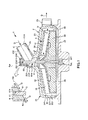
FIG. 1 is a sectional side view showing an embodiment of the centrifugal pump of the present invention. FIG. 2 is a cross-sectional plan view showing an embodiment of the centrifugal pump of the present invention. FIG. 3 is a perspective view of a first bearing provided in the centrifugal pump of the present invention. 4 is a cross-sectional view taken along line AA in FIG. In the following, for convenience of explanation, the upper side of FIGS. 1 and 3 (the same applies to FIGS. 5 to 9) is referred to as “upper” or “upper”, and the lower side is referred to as “lower” or “lower”.
図1に示す遠心ポンプ1は、中空体で構成されたハウジング2と、ハウジング2内に回転可能に収納された回転体(インペラ)3と、回転体3をハウジング2に対し回転可能に支持する支持機構4とを備えている。以下、各部の構成について説明する。
A centrifugal pump 1 shown in FIG. 1 supports a
ハウジング2は、ハウジング本体20と、血液Qが流入する血液流入ポート25と、血液Qが流出する血液流出ポート26とを有している。
The
ハウジング本体20は、偏平な円筒状の部材で構成され、その上端を閉塞する天板21と、天板21の縁部から立設した側壁23と、下端を閉塞する底板22とを有している。そして、天板21と底板22と側壁23とで囲まれた偏平な空間(中空部)がポンプ室24となる。
The housing body 20 is composed of a flat cylindrical member, and includes a top plate 21 that closes the upper end thereof, a
血液流入ポート25と血液流出ポート26とは、それぞれ、ポンプ室24に連通している。そして、血液流入ポート25から流入した血液Qは、ポンプ室24を介して、血液流出ポート26から流出することができる。
The
図1に示すように、血液流入ポート25は、天板21(一端部)の中心部に管状(円筒状)に突出形成されている。血液流入ポート25は、その長手方向の途中が屈曲しており、当該屈曲部251を境界部として天板21側の根元部252と、それと反対側の接続部253とに分けることができる。接続部253は、回転体3の回転軸に対して傾斜して設けられている。この接続部253には、例えば血液回路を構成するチューブを接続することができる。
As shown in FIG. 1, the
図2に示すように、血液流出ポート26は、側壁23の外周面(外周部)231に管状に突出形成されている。この血液流出ポート26は、側壁23の外周面231の接線方向に向かって突出している。
As shown in FIG. 2, the
ハウジング本体20のポンプ室24内には、円盤状をなす回転体3が同心的に配置されている。この回転体3は、回転することにより、血液Qに遠心力を付与する遠心力付与部材である。
In the
図2に示すように、回転体3は、血液Qが通過する複数本(図示の構成では6本)の血液流路31を有している。これらの血液流路31は、回転体3の中心から放射状に形成されている。また、各血液流路31の回転体3の中心側の部分同士は、互いに合流(交差)しており、回転体3の上面32に開口している。一方、血液流路31の回転体3の中心側と反対側の部分は、それぞれ、回転体3の外周面33に開口している。また、回転体3の外周面33とハウジング2の側壁23の内周面232との間には、間隙241が形成されている。
As shown in FIG. 2, the rotator 3 has a plurality (six in the illustrated configuration) of
そして、このような回転体3がハウジング2を上から見たような図2のように軸部材5を中心に時計回りに回転すると、血液流入ポート25から流入した血液Qは、各血液流路31にその回転体3の中心側の部分から入り込み、遠心力を受けて、血液流路31を流下する。この流下した血液Qは、間隙241内に流出する。その後、血液Qは、間隙241内で図2中の時計回りの回転力を受けて、血液流出ポート26に至ると、当該血液流出ポート26から確実に排出されることとなる。
When such a rotating body 3 rotates clockwise about the
図1に示すように、回転体3には、血液流路31の下側の部分に、磁石が設置されている。なお、図1に示す構成では、複数(例えば6つ)の永久磁石34を用いている。遠心ポンプ1を駆動するに際しては、後述する軸部材5が鉛直方向と平行となるようにハウジング2の底板22を下側にして、当該遠心ポンプ1を外部駆動手段(図示せず)に装着する。この装着状態で遠心ポンプ1が使用される。外部駆動手段は、例えば、モータと、モータに連結された永久磁石とを有し、この永久磁石が遠心ポンプ1に内蔵された永久磁石34と磁力により引き付け合う。そして、この状態でモータが回転すると、その回転力が前記引き付け合う磁石同士を介して伝達されて、回転体3も回転することができる。
As shown in FIG. 1, the rotating body 3 is provided with a magnet in a lower portion of the
なお、回転体3の直径は、特に限定されないが、例えば、20〜200mmであるのが好ましく、30〜100mmであるのがより好ましい。回転体3の厚さは、特に限定されないが、例えば、3〜40mmであるのが好ましく、5〜30mmであるのがより好ましい。回転体3の最大回転数は、特に限定されないが、例えば、2000〜6000rpmであるのが好ましく、2500〜5000rpmであるのがより好ましい。 The diameter of the rotating body 3 is not particularly limited, but is preferably 20 to 200 mm, for example, and more preferably 30 to 100 mm. Although the thickness of the rotary body 3 is not specifically limited, For example, it is preferable that it is 3-40 mm, and it is more preferable that it is 5-30 mm. Although the maximum rotation speed of the rotary body 3 is not specifically limited, For example, it is preferable that it is 2000-6000 rpm, and it is more preferable that it is 2500-5000 rpm.
また、回転体3およびハウジング2の構成材料としては、特に限定されず、例えば、硬質ポリ塩化ビニル、ポリエチレン、ポリプロピレン、ポリスチレン、ポリカーボネート、アクリル樹脂、ポリメチルメタクリレート(PMMA)等のアクリル系樹脂、ポリエチレ
ンテレフタレート(PET)、ポリブチレンテレフタレート(PBT)のようなポリエステル、ポリサルフォン、ポリアリレート等の各種硬質樹脂が挙げられる。また、これらの構成材料のうちでも、特に、血液Qとの適合性に優れ、また、透明性、成形加工性に優れるという点で、ポリカーボネート、アクリル樹脂が好ましい。
Moreover, it does not specifically limit as a constituent material of the rotary body 3 and the
図1に示すように、回転体3は、支持機構4を介してハウジング2に対し回転可能に支持されている。支持機構4は、軸部材5と、軸部材5の上端部(一端部)を回転可能に支持する第1の軸受け6と、軸部材5の下端部(他端部)を回転可能に支持する第2の軸受け7とを有している。
As shown in FIG. 1, the rotating body 3 is supported to be rotatable with respect to the
軸部材5は、回転体3の回転中心に設置されている。軸部材5は、両端部が丸みを帯びた棒状の部材で構成されている。軸部材5の構成材料としてセラミックを用いる場合、軸部材5の両端部は、研磨を施すことで軸部材5が回転する際の両端部の摺動性が向上する。また、軸部材5の構成材料として金属材料を用いる場合、軸部材5の両端部には、研磨を施した上で、例えば、ダイヤモンドライクカーボン(DLC)やチタン等のコーティングが施されていてもよい。これにより、軸部材5が回転する際の両端部の摺動性や耐久性が向上する。
The
第1の軸受け6は、血液流入ポート25の接続部253の内周部に凹没して形成された第1の軸受け設置部(凹部)254に設置、固定されている。第2の軸受け7は、ハウジング2の底板22の中心部に凹没して形成された第2の軸受け設置部221に設置、固定されている。なお、第1の軸受け6、第2の軸受け7のハウジング2に対する固定方法としては、特に限定されないが、例えば、嵌合による方法、接着(接着剤や溶媒による接着)による方法、融着(熱融着、高周波融着、超音波融着等)による方法、インサート成形による方法等が挙げられる。
The
図1および図3に示すように、第1の軸受け6は、外形形状が円柱状をなし、回転体3の回転中心方向に延在している。第1の軸受け6は、軸部材5の上端部が挿入される挿入部61を有している。挿入部61は、第1の軸受け6の下面62に開放する凹部で構成されている。また、挿入部61の底部は、軸部材5の上端面と接触して支持する支持面611となっており、軸部材5の上端面の形状に沿って湾曲している。
As shown in FIGS. 1 and 3, the
ここで、第1の軸受け6の下面(血液流路形成面)62は、血液流入ポート25の内側に臨んでおり、血液流入ポート25(接続部253)の内周面255とともに血液の流路を形成している。この第1の軸受け6の下面62は、血液流入ポート25の内周面255と同じ方向に、かつ、同じ傾斜角度で傾斜している。また、第1の軸受け6の下面62は、血液流入ポート25の内周面255と血液流入ポート25(接続部253)の中心軸Oからの距離が同じになっている。すなわち、第1の軸受け6の下面62と血液流入ポート25の内周面255とは境界部で段差のない連続面になっており、第1の軸受け6の下面62は、血液流入ポート25の内周面255と、血液流入ポート25の径方向の位置が同じになっていると言える。
Here, the lower surface (blood channel forming surface) 62 of the
このような構成によれば、血液Qが滞留し得る段差を解消することができる。これにより、図1中の拡大部分に示すように、血液流入ポート25内を流下する血液Qが、血液流入ポート25の内周面255と第1の軸受け6の下面62との境界部付近を流下する際、円滑に流下することができる。よって、血液流入ポート25内に血液Qが滞留し得る滞留部が生じるのを効果的に防止または抑制することができる。その結果、血液流入ポート25内(特に、軸部材5の外周部)に血栓が形成されるのを効果的に防止または抑制することができる。さらに、血液Qが滞留し得る段差を解消されていることにより、使用開始時に遠心ポンプ1に血液を充填する際の気泡抜きを容易にすることができたり、血液Q中に気泡が混在している場合、当該気泡の滞留も防止することができる。
According to such a structure, the level | step difference in which the blood Q can stay can be eliminated. As a result, as shown in the enlarged portion in FIG. 1, the blood Q flowing down in the
また、図4に示すように、第1の軸受け6の下面62は、血液流入ポート25の内周面255の曲率と同じ曲率で湾曲している。このため、図4中に示す断面において、第1の軸受け6の下面62は、血液流入ポート25の内周面255とともに円形の内面を形成している。これにより、血液Qは、血液流入ポート25内をより円滑に流下することができる。
As shown in FIG. 4, the
第1の軸受け6と第2の軸受け7とは、同じ材料で構成されるのが好ましい。また、各軸受けと軸部材5とは、互いに同じ材料で構成されていてもよいし、異なる材料で構成されていてもよい。各軸受けと軸部材5とが互いに同じ材料で構成されている場合、各構成材料に硬質のものを用い、例えば、第1の軸受け6と第2の軸受け7と軸部材5とをそれぞれ金属材料またはセラミックスで構成することができる。各軸受けと軸部材5とが互いに異なる材料で構成されている場合、軸部材5の構成材料に硬質のものを用い、各軸受けの構成材料に軸部材5よりも軟質のものを用い、例えば、軸部材5を金属材料やセラミックスで構成し、第1の軸受け6と第2の軸受け7とをそれぞれ樹脂材料で構成することができる。
The
樹脂材料としては、特に限定されず、例えば、ポリエチレン、ポリプロピレン、エチレン−酢酸ビニル共重合体等のポリオレフィン、変性ポリオレフィン、ポリアミド(例:ナイロン6、ナイロン46、ナイロン66、ナイロン610、ナイロン612、ナイロン11、ナイロン12、ナイロン6−12、ナイロン6−66)、熱可塑性ポリイミド、芳香族ポリエステル等の液晶ポリマー、ポリフェニレンオキシド、ポリフェニレンサルファイド、ポリカーボネート、ポリメチルメタクリレート、ポリエーテル、ポリエーテルエーテルケトン、ポリエーテルイミド、ポリアセタール、スチレン系、ポリオレフィン系、ポリ塩化ビニル系、ポリウレタン系、ポリエステル系、ポリアミド系、ポリブタジエン系、トランスポリイソプレン系、フッ素ゴム系、塩素化ポリエチレン系等の各種熱可塑性エラストマー等、またはこれらを主とする共重合体、ブレンド体、ポリマーアロイ等が挙げられ、これらのうちの1種または2種以上を混合して用いることができる。これらの中でも、特に平均分子量が大きい(例えば、200万〜1000万程度)のポリエチレン(超高分子ポリエチレン)が好ましい。特に、第1の軸受け6を超高分子ポリエチレンで構成することにより、第1の軸受け6の耐摩耗性、加工性および自己潤滑性を高めることができる。
The resin material is not particularly limited. For example, polyolefins such as polyethylene, polypropylene, and ethylene-vinyl acetate copolymer, modified polyolefins, polyamides (eg,
金属材料としては、特に限定されず、例えば、ステンレス鋼等が挙げられる。また、金属材料の他に、セラミックス等も用いることができる。また、このような硬質材料(金属材料やセラミックス)の硬度(ビッカース硬度(Hv))としては、特に限定されず、例えば、50以上であるのが好ましく、100以上であるのがより好ましい。 It does not specifically limit as a metal material, For example, stainless steel etc. are mentioned. Moreover, ceramics etc. can be used besides a metal material. Moreover, it does not specifically limit as hardness (Vickers hardness (Hv)) of such a hard material (a metal material or ceramics), For example, it is preferable that it is 50 or more, and it is more preferable that it is 100 or more.
<第2実施形態>
図5は、本発明の遠心ポンプ(第2実施形態)が備える第1の軸受けの斜視図である。
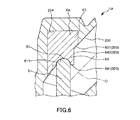
図6は、本発明の遠心ポンプ(第2実施形態)の拡大断面図である。
Second Embodiment
FIG. 5 is a perspective view of a first bearing provided in the centrifugal pump (second embodiment) of the present invention.
FIG. 6 is an enlarged cross-sectional view of the centrifugal pump (second embodiment) of the present invention.
以下、この図を参照して本発明の遠心ポンプの第2実施形態について説明するが、前述した実施形態との相違点を中心に説明し、同様の事項はその説明を省略する。 Hereinafter, the second embodiment of the centrifugal pump of the present invention will be described with reference to this figure. However, the difference from the above-described embodiment will be mainly described, and the description of the same matters will be omitted.
本実施形態は、第1の軸受けの形状が異なること以外は前記第1実施形態と同様である。 This embodiment is the same as the first embodiment except that the shape of the first bearing is different.
図5および図6に示すように、遠心ポンプ1Aの第1の軸受け6Aは、互いに外径が異なる大径部63および小径部64を有している。
As shown in FIGS. 5 and 6, the
大径部63は、第1の軸受け設置部254内に挿入されている部分である。大径部63の血液流入ポート25内に臨む面、すなわち、下面631(以下、「第1の血液流路形成面200」とも言う)は、血液流入ポート25の内周面255と同じ方向に、かつ、同じ傾斜角度で傾斜している。また、大径部63の下面631は、血液流入ポート25の内周面255と血液流入ポート25(接続部253)の中心軸Oからの径方向の距離が同じになっている。さらに、大径部63の下面631は、血液流入ポート25の内周面255の曲率と同じ曲率で湾曲している。このような大径部63によって、血液Qの円滑な血流を確保することができる。
The large-
小径部64は、大径部63よりも血液流入ポート25の中心軸O側に位置している。小径部64の下面641は、軸部材5の回転中心に対して垂直な面になっている。なお、小径部64の下面641および外周面642で第2の血液流路形成面300が構成されている。
The
また、小径部64では、第1実施形態での挿入部61が省略されており、軸部材5の上端面に沿って窪んだ支持面611が形成されている。これにより、軸部材5が第1の軸受け6に挿入された部分をできるだけ少なくすることができる。
Further, in the
また、図6に示すように、支持面611は、血液流入ポート25の内周面255よりも血液流入ポート25の中心軸O側に位置している。これにより、軸部材5の上端面51と支持面611との間に入り込んだ血液Qは、血液流入ポート25を流下してくる血液Qによって押し出される。よって、血液Qが軸部材5の上端面51と支持面611との間に血液Qが滞留するのを効果的に防止または抑制することができる。その結果、血液Qが軸部材5の上端面51と支持面611との間に血栓が形成されるのを防止または抑制することができる。
As shown in FIG. 6, the
このように、第1の軸受け6Aでは、血液流入ポート25内に臨む面が、第1の血液流路形成面200と、第2の血液流路形成面300とが第1の軸受け6Aの長手方向に沿ってずれた多段構造になっている。このような構成によれば、大径部63によって円滑な血流を確保することができるとともに、小径部64によって軸部材5の上端面51と支持面611との間に血栓が形成されるのを防止または抑制することができる。
As described above, in the
<第3実施形態>
図7は、本発明の遠心ポンプ(第3実施形態)が備える第1の軸受けの斜視図である。図8は、本発明の遠心ポンプ(第3実施形態)の拡大断面図である。
<Third Embodiment>
FIG. 7 is a perspective view of a first bearing provided in the centrifugal pump (third embodiment) of the present invention. FIG. 8 is an enlarged cross-sectional view of the centrifugal pump (third embodiment) of the present invention.
以下、この図を参照して本発明の遠心ポンプの第3実施形態について説明するが、前述した実施形態との相違点を中心に説明し、同様の事項はその説明を省略する。
本実施形態は、小径部の形状が異なること以外は前記第2実施形態と同様である。
Hereinafter, the third embodiment of the centrifugal pump of the present invention will be described with reference to this figure. However, the difference from the above-described embodiment will be mainly described, and the description of the same matters will be omitted.
The present embodiment is the same as the second embodiment except that the shape of the small diameter portion is different.
図7および図8に示すように、遠心ポンプ1Bの第1の軸受け6Bでは、小径部64が第2実施形態の小径部よりも長い。また、第2の血液流路形成面300(特に、下面641)は、血液流入ポート25の径方向において、大径部63の下面631よりも中心軸O側に位置している。本実施形態では、小径部64の下面641は、中心軸Oと交わっている。このため、支持面611は、中心軸O付近に位置することとなる。このため、血液流入ポート25の中心軸O付近では、血液Qの流速が比較的速い部分に支持面611が位置することとなる。これにより、軸部材5の上端面51と支持面611との間に入り込んだ血液Qは、血液流入ポート25を流下してくる血液Qによってより確実に押し出される。よって、血液Qが軸部材5の上端面51と支持面611との間に血液Qが滞留するのがより確実に防止または抑制される。その結果、軸部材5の上端面51と支持面611との間に血栓が形成されるのをより効果的に防止または抑制することができる。
As shown in FIGS. 7 and 8, in the
<第4実施形態>
図9は、本発明の遠心ポンプ(第4実施形態)の拡大断面図である。図10は、本発明の遠心ポンプ(第4実施形態)を血液流入ポートの開口側から見た図である。
<Fourth embodiment>
FIG. 9 is an enlarged cross-sectional view of the centrifugal pump (fourth embodiment) of the present invention. FIG. 10 is a view of the centrifugal pump (fourth embodiment) of the present invention viewed from the opening side of the blood inflow port.
以下、この図を参照して本発明の遠心ポンプの第4実施形態について説明するが、前述した実施形態との相違点を中心に説明し、同様の事項はその説明を省略する。 Hereinafter, the fourth embodiment of the centrifugal pump of the present invention will be described with reference to this figure. However, the difference from the above-described embodiment will be mainly described, and the description of the same matters will be omitted.
本実施形態は、整流部が設けられていることと、第1の軸受けの形状が異なること以外は前述の第1実施形態と略同様である。 The present embodiment is substantially the same as the first embodiment described above except that the rectifying unit is provided and the shape of the first bearing is different.
図9および図10に示すように、遠心ポンプ1Cの第1の軸受け6Cでは、下面62は、第1の軸受け設置部254の深さ方向と垂直になっている。また、下面62は、血液流入ポート25の径方向において、血液流入ポート25の内周面255よりも中心軸O側に位置している。
As shown in FIGS. 9 and 10, the
また、血液流入ポート25には、第1の軸受け6の上流側に設けられ、血液Qの流れを整流する整流部256が一体的に形成されている。整流部256は、血液流入ポート25の内周面255から中心軸O側に向って突出して設けられている。また、整流部256は、中心軸Oに沿って延在している。この整流部256により、血液流入ポート25を流下する血液Qは、整流部256を介して両側に流れる(図10参照)。これにより、血液Qは、整流部256の下流側に位置する第1の軸受け6を迂回するようにして血液流入ポート25内を流下する。よって、第1の軸受け6の周辺に血液Qが滞留するのをさらに効果的に防止または抑制することができる。よって、第1の軸受け6の外周部に血栓が形成されるのをさらに効果的に防止または抑制することができる。
Further, the
また、整流部256は、横断面形状が中心軸O側に頂部を有する略三角形をなしている。そして、図10に示すように、整流部256は、上流側にいくに従って幅および突出高さが徐々に小さくなっている。これにより、血液流入ポート25を流下する血液Qは、上流側から緩やかに整流される。
Further, the rectifying
さらに、図10中の補助断面図に示すように、整流部256の一対の側面257は、それぞれ、互いに接近する方向に湾曲している。これにより、血液流入ポート25を流下する血液Qは、上流側から、さらに緩やかに整流される。
Furthermore, as shown in the auxiliary sectional view in FIG. 10, the pair of side surfaces 257 of the rectifying
このような構成によれば、整流部256は、上記効果をより確実に発揮することができる。
According to such a configuration, the rectifying
また、整流部256の下流側の端部は、第1の軸受け6Cの外周部に接触している。これにより、第1の軸受け6Cには、例えば、回転体3が回転する際に生じる得るラジアル方向への力がかかるため、第1の軸受け6Cが変形することを防止する、すなわち、補強部として機能し得る。その結果、遠心ポンプ1Cの高寿命化を図ることができる。さらに、血液Qの流圧による第1の軸受け6Cへの影響を軽減することができ、血液損傷を軽減することができる。
Further, the downstream end portion of the rectifying
以上、本発明の遠心ポンプを図示の実施形態について説明したが、本発明は、これに限定されるものではなく、遠心ポンプを構成する各部は、同様の機能を発揮し得る任意の構成のものと置換することができる。また、任意の構成物が付加されていてもよい。 As mentioned above, although the centrifugal pump of this invention was demonstrated about embodiment of illustration, this invention is not limited to this, Each part which comprises a centrifugal pump is a thing of arbitrary structures which can exhibit the same function. Can be substituted. Moreover, arbitrary components may be added.
なお、前記第1実施形態では、第1の軸受けの下面は、血液流入ポートの内周面と、血液流入ポートの中心軸との距離が同じであるが、本発明ではこれに限定されず、血液流入ポートの内周面よりも血液流入ポートの中心軸側に位置していてもよい。 In the first embodiment, the lower surface of the first bearing has the same distance between the inner peripheral surface of the blood inlet port and the central axis of the blood inlet port, but the present invention is not limited to this. You may be located in the center axis | shaft side of a blood inflow port rather than the internal peripheral surface of a blood inflow port.
また、前記各実施形態では、各軸受けとハウジングとは、別体で構成されているが、本発明ではこれに限定されず、各軸受けとハウジングとは、一体的に構成されていてもよい。 Moreover, in each said embodiment, although each bearing and a housing are comprised separately, in this invention, it is not limited to this, Each bearing and a housing may be comprised integrally.
また、前記第2実施形態では、大径部の下面は、血液流入ポートの内周面と、血液流入ポートの径方向の位置が同じであるが、本発明ではこれに限定されず、血液流入ポートの内周面よりも血液流入ポートの中心軸側に位置していてもよい。 In the second embodiment, the lower surface of the large-diameter portion is the same as the inner peripheral surface of the blood inflow port and the radial position of the blood inflow port. You may be located in the center axis | shaft side of the blood inflow port rather than the internal peripheral surface of a port.
また、前記第2実施形態および第3実施形態では、小径部の下面は、第1の軸受けの長手方向に対して垂直であるが、本発明ではこれに限定されず、傾斜していてもよい。 In the second embodiment and the third embodiment, the lower surface of the small diameter portion is perpendicular to the longitudinal direction of the first bearing. However, the present invention is not limited to this and may be inclined. .
また、前記第4実施形態では、整流部は、血液流入ポートの中心軸方向に延在しているが、本発明ではこれに限定されず、例えば、長手方向の途中が欠損して間欠的に設けられていてもよい。 In the fourth embodiment, the rectifier extends in the central axis direction of the blood inflow port. However, the present invention is not limited to this, and for example, the middle in the longitudinal direction is lost and intermittently. It may be provided.
また、前記第4実施形態では、整流部は、横断面形状が略三角形をなしているが、本発明ではこれに限定されず、例えば、円形、半円形、四角形またはそれ以上の多角形等であってもよい。 Moreover, in the said 4th Embodiment, although the cross-sectional shape has comprised the substantially triangular shape in the said 4th Embodiment, it is not limited to this in this invention, For example, circular, a semicircle, a quadrangle | tetragon or more polygons etc. There may be.
また、前記第4実施形態では、整流部は、下流側が第1の軸受けと接触しているが、本発明ではこれに限定されず、第1の軸受けと離間していてもよい。 Moreover, in the said 4th Embodiment, although the rectification | straightening part is contacting the 1st bearing in the downstream, it is not limited to this in this invention, You may space apart from the 1st bearing.
また、前記第4実施形態では、整流部は、ハウジング(血液流入ポート)と一体的に形成されているが、本発明ではこれに限定されず、ハウジングとは別体で構成されていてもよく、第1の軸受けと一体的に形成されていてもよい。 Moreover, in the said 4th Embodiment, although the rectification | straightening part is integrally formed with the housing (blood inflow port), it is not limited to this in this invention, You may be comprised separately from the housing. The first bearing may be formed integrally with the first bearing.
本発明の遠心ポンプは、中空体で構成されたハウジング本体と、前記ハウジング本体から筒状に突出形成され、前記ハウジング本体に連通し、血液が流入する血液流入ポートと、前記ハウジング本体の前記血液流入ポートとは異なる位置に設けられ、血液が流出する血液流出ポートとを有するハウジングと、前記中空部内に回転可能に収納され、その回転により血液に遠心力を付与する遠心力付与部材と、前記遠心力付与部材を前記ハウジングに対し回転可能に支持する支持機構とを備え、前記支持機構は、前記遠心力付与部材の回転中心に設置された軸部材と、前記軸部材の一端部を回転可能に支持し、前記血液流入ポートの内周部に設置された第1の軸受けと、前記軸部材の他端部を回転可能に支持する第2の軸受けとを有し、前記第1の軸受けは、前記血液流入ポートの内側に臨み、前記血液流入ポートの内周面とともに血液の流路を形成する血液流路形成面を有し、前記血液流路形成面は、前記血液流入ポートの内周面と、前記血液流入ポートの中心軸からの距離が同じか、または、前記血液流入ポートの内周面よりも前記血液流入ポートの中心軸側に位置していることを特徴とする。そのため、血液流入ポート内において血栓が形成されるのを効果的に防止または抑制することができる。 The centrifugal pump according to the present invention includes a housing body constituted by a hollow body, a blood projecting port formed in a cylindrical shape from the housing body, communicating with the housing body, and receiving blood, and the blood of the housing body. A housing that is provided at a position different from the inflow port, and has a blood outflow port through which blood flows out; and a centrifugal force applying member that is rotatably accommodated in the hollow portion and applies centrifugal force to the blood by the rotation; A support mechanism that rotatably supports the centrifugal force application member with respect to the housing, and the support mechanism is capable of rotating a shaft member installed at a rotation center of the centrifugal force application member and one end of the shaft member. And a second bearing that rotatably supports the other end of the shaft member, and the first bearing is disposed on the inner periphery of the blood inlet port. The bearing has a blood flow path forming surface that faces the inside of the blood inflow port and forms a blood flow path together with an inner peripheral surface of the blood inflow port. The distance from the inner peripheral surface and the central axis of the blood inlet port is the same, or the inner peripheral surface of the blood inlet port is located closer to the central axis of the blood inlet port. Therefore, it is possible to effectively prevent or suppress the formation of thrombus in the blood inflow port.
1、1A、1B、1C 遠心ポンプ
2 ハウジング
20 ハウジング本体
21 天板
22 底板
221 第2の軸受け設置部
23 側壁
231 外周面
232 内周面
24 ポンプ室
241 間隙
25 血液流入ポート
251 屈曲部
252 根元部
253 接続部
254 第1の軸受け設置部
255 内周面
256 整流部
257 側面
26 血液流出ポート
3 回転体
31 血液流路
32 上面
33 外周面
34 永久磁石
4 支持機構
5 軸部材
51 上端面
6、6A、6B、6C 第1の軸受け
61 挿入部
611 支持面
62 下面
63 大径部
631 下面
64 小径部
641 下面
642 外周面
7 第2の軸受け
200 第1の血液流路形成面
300 第2の血液流路形成面
O 中心軸
Q 血液
1, 1A, 1B,
Claims (7)
前記中空部内に回転可能に収納され、その回転により血液に遠心力を付与する遠心力付与部材と、
前記遠心力付与部材を前記ハウジングに対し回転可能に支持する支持機構と、
血液の流れを整流する整流部とを備え、
前記支持機構は、前記遠心力付与部材の回転中心に設置された軸部材と、
前記軸部材の一端部を回転可能に支持し、前記血液流入ポートの内周部に設置された第1の軸受けと、
前記軸部材の他端部を回転可能に支持する第2の軸受けとを有し、
前記第1の軸受けは、前記血液流入ポートの内側に臨み、前記血液流入ポートの内周面とともに血液の流路を形成する血液流路形成面を有し、
前記血液流路形成面は、前記血液流入ポートの内周面と、前記血液流入ポートの中心軸からの距離が同じか、または、前記血液流入ポートの内周面よりも前記血液流入ポートの中心軸側に位置しており、
前記整流部は、前記血液流入ポートの内周部の前記第1の軸受けよりも上流側に突出形成され、前記血液流入ポートの中心軸に沿って延在し、横断面形状が、前記血液流入ポートの中心軸側に頂部を有する形状をなすものであり、上流側にいくに従って幅および突出高さが徐々に小さくなっていることを特徴とする遠心ポンプ。 A housing main body configured by a hollow body, formed in a cylindrical shape protruding from the housing main body, communicated with the housing main body, and a blood inflow port through which blood flows, and the blood inflow port of the housing main body at different positions A housing provided with a blood outlet port through which blood flows out;
A centrifugal force imparting member that is rotatably accommodated in the hollow portion and imparts centrifugal force to blood by the rotation,
A support mechanism for rotatably supporting the centrifugal force applying member with respect to the housing;
A rectifier that rectifies the flow of blood,
The support mechanism includes a shaft member installed at the center of rotation of the centrifugal force applying member,
A first bearing that rotatably supports one end of the shaft member and is disposed on an inner peripheral portion of the blood inflow port;
A second bearing that rotatably supports the other end of the shaft member;
The first bearing has a blood flow path forming surface that faces the inside of the blood inflow port and forms a blood flow path with an inner peripheral surface of the blood inflow port,
The blood flow path forming surface has the same distance from the inner peripheral surface of the blood inflow port and the central axis of the blood inflow port, or the center of the blood inflow port more than the inner peripheral surface of the blood inflow port Located on the shaft side,
The rectifying portion is formed to protrude upstream from the first bearing of the inner peripheral portion of the blood inflow port, extends along the central axis of the blood inflow port, and has a cross-sectional shape having the blood inflow portion. A centrifugal pump characterized in that it has a shape having a top on the central axis side of the port, and the width and protrusion height are gradually reduced toward the upstream side.
前記血液流路形成面は、前記血液流入ポートの内周面と同じ方向に傾斜している部分を有する請求項1に記載の遠心ポンプ。 The blood inflow port has a portion inclined with respect to the rotation center of the centrifugal force applying member,
The centrifugal pump according to claim 1, wherein the blood flow path forming surface has a portion inclined in the same direction as the inner peripheral surface of the blood inflow port.
前記血液流路形成面は、前記血液流入ポートの内周面の湾曲形状に沿って湾曲している部分を有する請求項1または2に記載の遠心ポンプ。 The blood inlet port has a cylindrical shape,
The centrifugal pump according to claim 1 or 2, wherein the blood flow path forming surface has a curved portion along a curved shape of an inner peripheral surface of the blood inflow port.
前記血液流路形成面は、前記第1の軸受けの長手方向に沿ってずれた多段構造になっており、第1の血液流路形成面と、前記第1の血液流路形成面よりも前記血液流入ポートの中心軸側に位置する第2の血液流路形成面とを有している請求項1ないし3のいずれか1項に記載の遠心ポンプ。 The first bearing has a cylindrical outer shape,
The blood flow path forming surface has a multi-stage structure shifted along the longitudinal direction of the first bearing, and the first blood flow path forming surface and the first blood flow path forming surface are more The centrifugal pump according to any one of claims 1 to 3, further comprising a second blood flow path forming surface located on a central axis side of the blood inflow port.
前記第1の血液流路形成面は、前記大径部の前記血液流入ポートの内側に臨む面で構成され、
前記第2の血液流路形成面は、前記小径部の前記血液流入ポートの内側に臨む面で構成されている請求項4に記載の遠心ポンプ。 The first bearing has a large diameter portion and a small diameter portion having different outer diameters,
The first blood flow path forming surface is configured by a surface facing the inside of the blood inlet port of the large diameter portion,
The centrifugal pump according to claim 4, wherein the second blood flow path forming surface is configured by a surface facing the inside of the blood inlet port of the small diameter portion.
前記支持面は、前記血液流入ポートの内周面よりも前記血液流入ポートの中心軸側に位置している請求項1ないし5のいずれか1項に記載の遠心ポンプ。 The first bearing has a support surface that supports and supports one end surface of the shaft member;
The centrifugal pump according to any one of claims 1 to 5, wherein the support surface is located closer to a central axis of the blood inlet port than an inner peripheral surface of the blood inlet port.
前記一対の側面は、それぞれ、互いに接近する方向に湾曲している請求項1ないし6のいずれか1項に記載の遠心ポンプ。 The rectifying unit has a pair of side surfaces located on opposite sides of each other via the top part,
The centrifugal pump according to any one of claims 1 to 6, wherein the pair of side surfaces are curved in directions approaching each other.
Applications Claiming Priority (2)
| Application Number | Priority Date | Filing Date | Title |
|---|---|---|---|
| JP2014191807 | 2014-09-19 | ||
| JP2014191807 | 2014-09-19 |
Related Parent Applications (1)
| Application Number | Title | Priority Date | Filing Date |
|---|---|---|---|
| JP2016548787A Division JP6306725B2 (en) | 2014-09-19 | 2015-08-21 | Centrifugal pump |
Publications (2)
| Publication Number | Publication Date |
|---|---|
| JP2018134428A JP2018134428A (en) | 2018-08-30 |
| JP6466609B2 true JP6466609B2 (en) | 2019-02-06 |
Family
ID=55533017
Family Applications (2)
| Application Number | Title | Priority Date | Filing Date |
|---|---|---|---|
| JP2016548787A Active JP6306725B2 (en) | 2014-09-19 | 2015-08-21 | Centrifugal pump |
| JP2018042203A Active JP6466609B2 (en) | 2014-09-19 | 2018-03-08 | Centrifugal pump |
Family Applications Before (1)
| Application Number | Title | Priority Date | Filing Date |
|---|---|---|---|
| JP2016548787A Active JP6306725B2 (en) | 2014-09-19 | 2015-08-21 | Centrifugal pump |
Country Status (4)
| Country | Link |
|---|---|
| US (1) | US10272185B2 (en) |
| EP (1) | EP3196470B1 (en) |
| JP (2) | JP6306725B2 (en) |
| WO (1) | WO2016042975A1 (en) |
Families Citing this family (5)
| Publication number | Priority date | Publication date | Assignee | Title |
|---|---|---|---|---|
| JP6208374B2 (en) * | 2014-09-19 | 2017-10-04 | テルモ株式会社 | Centrifugal pump |
| CN111298221A (en) * | 2018-12-12 | 2020-06-19 | 深圳核心医疗科技有限公司 | Ventricular assist device |
| WO2020146821A1 (en) * | 2019-01-10 | 2020-07-16 | Burgreen Gregory W | Passively flushed bearing for cardiovascular turbomachinery |
| JP7422729B2 (en) | 2019-02-19 | 2024-01-26 | テルモ株式会社 | pump equipment |
| DE102020117818A1 (en) * | 2020-07-07 | 2022-01-13 | Resuscitec Gmbh | blood pump |
Family Cites Families (11)
| Publication number | Priority date | Publication date | Assignee | Title |
|---|---|---|---|---|
| US5458459A (en) * | 1992-07-30 | 1995-10-17 | Haemonetics Corporation | Centrifugal blood pump with impeller blades forming a spin inducer |
| JP3399528B2 (en) * | 1992-07-30 | 2003-04-21 | コーブ カルディオバスキュラー, インコーポレイテッド | Spiral blood pump |
| US5713730A (en) * | 1992-09-04 | 1998-02-03 | Kyocera Corporation | Ceramic pivot bearing arrangement for a sealless blood pump |
| US5527159A (en) * | 1993-11-10 | 1996-06-18 | The United States Of America As Represented By The Administrator Of The National Aeronautics And Space Administration | Rotary blood pump |
| US5613935A (en) * | 1994-12-16 | 1997-03-25 | Jarvik; Robert | High reliability cardiac assist system |
| US6746416B2 (en) * | 2001-12-05 | 2004-06-08 | Spin Corporation | Duplex blood pump for heart surgery |
| JP2005146981A (en) * | 2003-11-14 | 2005-06-09 | Kawamoto Pump Mfg Co Ltd | Line pump |
| US7210898B2 (en) * | 2004-10-15 | 2007-05-01 | Lloyd Hubbard | Gas removal from a centrifugal pump |
| JP4548450B2 (en) | 2007-05-29 | 2010-09-22 | 株式会社ジェイ・エム・エス | Turbo blood pump |
| JP5743567B2 (en) * | 2011-01-25 | 2015-07-01 | 京セラメディカル株式会社 | Centrifugal blood pump |
| JP5739287B2 (en) * | 2011-09-05 | 2015-06-24 | テルモ株式会社 | Centrifugal pump |
-
2015
- 2015-08-21 JP JP2016548787A patent/JP6306725B2/en active Active
- 2015-08-21 WO PCT/JP2015/073549 patent/WO2016042975A1/en active Application Filing
- 2015-08-21 EP EP15842515.7A patent/EP3196470B1/en active Active
-
2017
- 2017-01-12 US US15/404,377 patent/US10272185B2/en active Active
-
2018
- 2018-03-08 JP JP2018042203A patent/JP6466609B2/en active Active
Also Published As
| Publication number | Publication date |
|---|---|
| EP3196470A1 (en) | 2017-07-26 |
| JPWO2016042975A1 (en) | 2017-04-27 |
| JP6306725B2 (en) | 2018-04-04 |
| EP3196470B1 (en) | 2020-08-12 |
| US10272185B2 (en) | 2019-04-30 |
| EP3196470A4 (en) | 2018-04-11 |
| WO2016042975A1 (en) | 2016-03-24 |
| US20170122337A1 (en) | 2017-05-04 |
| JP2018134428A (en) | 2018-08-30 |
Similar Documents
| Publication | Publication Date | Title |
|---|---|---|
| JP6466609B2 (en) | Centrifugal pump | |
| JP6208374B2 (en) | Centrifugal pump | |
| JP4548450B2 (en) | Turbo blood pump | |
| US8523539B2 (en) | Centrifugal pump | |
| JP3582467B2 (en) | Turbo blood pump | |
| US20160279311A1 (en) | Axial flow blood pump | |
| JP5739287B2 (en) | Centrifugal pump | |
| JP2008545083A (en) | Axial pump with helical blades | |
| JP6503301B2 (en) | Centrifugal pump | |
| JP2009523488A5 (en) | ||
| JP6134702B2 (en) | Centrifugal pump and centrifugal pump manufacturing method | |
| JP5673795B2 (en) | Turbo blood pump and method for manufacturing the same | |
| KR101694847B1 (en) | spurt pump | |
| JP4912090B2 (en) | Impeller and fuel pump using impeller | |
| JP6276708B2 (en) | Centrifugal pump | |
| US6824358B2 (en) | Turbo blood pump | |
| JP2012161526A (en) | Centrifugal blood pump and centrifugal blood pump device | |
| JP5623203B2 (en) | Centrifugal blood pump and centrifugal blood pump device | |
| JP2002085554A (en) | Turbo type blood pump | |
| JP2015155682A (en) | Noncontact bearing pump | |
| JP2015151995A (en) | pump | |
| KR100985200B1 (en) | Motor pump | |
| JP3247717B2 (en) | Blood pump |
Legal Events
| Date | Code | Title | Description |
|---|---|---|---|
| A977 | Report on retrieval |
Free format text: JAPANESE INTERMEDIATE CODE: A971007 Effective date: 20181211 |
|
| TRDD | Decision of grant or rejection written | ||
| A01 | Written decision to grant a patent or to grant a registration (utility model) |
Free format text: JAPANESE INTERMEDIATE CODE: A01 Effective date: 20181218 |
|
| A61 | First payment of annual fees (during grant procedure) |
Free format text: JAPANESE INTERMEDIATE CODE: A61 Effective date: 20190109 |
|
| R150 | Certificate of patent or registration of utility model |
Ref document number: 6466609 Country of ref document: JP Free format text: JAPANESE INTERMEDIATE CODE: R150 |
|
| R250 | Receipt of annual fees |
Free format text: JAPANESE INTERMEDIATE CODE: R250 |
|
| R250 | Receipt of annual fees |
Free format text: JAPANESE INTERMEDIATE CODE: R250 |
|
| R250 | Receipt of annual fees |
Free format text: JAPANESE INTERMEDIATE CODE: R250 |