JP6464729B2 - Display device and control method of display device - Google Patents
Display device and control method of display device Download PDFInfo
- Publication number
- JP6464729B2 JP6464729B2 JP2014260216A JP2014260216A JP6464729B2 JP 6464729 B2 JP6464729 B2 JP 6464729B2 JP 2014260216 A JP2014260216 A JP 2014260216A JP 2014260216 A JP2014260216 A JP 2014260216A JP 6464729 B2 JP6464729 B2 JP 6464729B2
- Authority
- JP
- Japan
- Prior art keywords
- display
- unit
- control unit
- value
- light
- Prior art date
- Legal status (The legal status is an assumption and is not a legal conclusion. Google has not performed a legal analysis and makes no representation as to the accuracy of the status listed.)
- Active
Links
Images


Landscapes
- Controls And Circuits For Display Device (AREA)
Description
本発明は、表示装置、及び、表示装置の制御方法に関する。 The present invention relates to a display device and a display device control method.
従来、使用者の頭部に装着される表示装置が知られている(例えば、特許文献1参照)。光を発する表示装置においては、表示装置が発する光の強さ、言い換えれば表示の輝度、或いは明るさを調整できることが一般的であり、頭部に装着される表示装置においても同様である。 Conventionally, a display device mounted on a user's head is known (see, for example, Patent Document 1). In a display device that emits light, it is common to be able to adjust the intensity of light emitted from the display device, in other words, the luminance or brightness of the display, and the same applies to a display device mounted on the head.
特許文献1に記載された表示装置のように、使用者の眼と表示装置とが近い場合、表示の輝度を、使用者の好みに合わせて設定することが求められる。表示装置の表示の明るさの感じ方は、使用者の感覚だけでなく、使用者の眼に入射する外光など他の要素の影響を受ける。例えば、表示装置が発する光と外光とが同じ方向から使用者の眼に入射する場合と、外光が入射しない場合とでは、表示装置の表示の輝度の感じ方は大きく変わる可能性がある。このため、表示装置の表示の輝度に関する制御が複雑化しやすく、処理負荷が高くなったり、使用者が望むような輝度の調整が難しくなったりするという問題があった。
本発明は上記事情に鑑みてなされたものであり、使用者の頭部に装着される表示装置において、簡易な処理により、表示の輝度を適切に調整することを目的とする。
When the user's eye is close to the display device as in the display device described in Patent Document 1, it is required to set the display brightness according to the user's preference. The display brightness of the display device is influenced not only by the user's senses but also by other factors such as external light incident on the user's eyes. For example, there is a possibility that how the display device perceives the brightness of the display device varies greatly between the case where the light emitted from the display device and the outside light enter the user's eyes from the same direction and the case where the outside light does not enter. . For this reason, there is a problem that the control regarding the display brightness of the display device is likely to be complicated, the processing load becomes high, and it is difficult to adjust the brightness as desired by the user.
The present invention has been made in view of the above circumstances, and an object of the present invention is to appropriately adjust the display brightness by a simple process in a display device mounted on a user's head.
上記目的を達成するために、本発明は、使用者の頭部に装着される頭部装着型の表示装置であって、前記使用者の眼に画像光を照射する表示部と、光を検出する光検出部と、前記表示部の表示の輝度を調整する調整処理、及び、前記光検出部の検出値に基づいて補正係数を求め前記表示部の表示の輝度を補正する補正処理を実行する制御部と、を備えることを特徴とする。
本発明によれば、表示の輝度を調整する処理と、光検出部の検出値に基づき表示の輝度を変化させる処理とを容易に実行できるので、負荷の軽い処理により表示の輝度を適切に調整できる。
In order to achieve the above object, the present invention provides a head-mounted display device mounted on a user's head, the display unit for irradiating image light to the user's eyes, and light detection And a correction process for adjusting the display luminance of the display unit, and a correction process for correcting the display luminance of the display unit by obtaining a correction coefficient based on the detection value of the light detection unit. And a control unit.
According to the present invention, the process of adjusting the display brightness and the process of changing the display brightness based on the detection value of the light detection unit can be easily executed. Therefore, the display brightness can be appropriately adjusted by the light load process. it can.
また、本発明は、上記表示装置において、前記制御部は、前記光検出部の検出値を用いて前記補正係数を求め、求めた補正係数に従って、前記補正処理で前記調整処理後の前記表示部の表示の輝度を補正すること、を特徴とする。
本発明によれば、表示の輝度を調整した後に、調整した輝度を光検出部の検出値に対応して変化させる処理を、容易に実行できる。
In the display device according to the aspect of the invention, the control unit obtains the correction coefficient using a detection value of the light detection unit, and the display unit after the adjustment process in the correction process according to the obtained correction coefficient. The display brightness is corrected.
According to the present invention, it is possible to easily execute the process of changing the adjusted luminance corresponding to the detection value of the light detection unit after adjusting the luminance of the display.
また、本発明は、上記表示装置において、前記制御部は、前記光検出部の検出値を予め設定された演算式に適用して演算処理を行うことにより前記補正係数を求めること、を特徴とする。
本発明によれば、演算処理によって、検出値に対応する補正係数を容易に求めることができる。
Further, the present invention is characterized in that, in the display device, the control unit obtains the correction coefficient by performing a calculation process by applying a detection value of the light detection unit to a predetermined calculation formula. To do.
According to the present invention, the correction coefficient corresponding to the detected value can be easily obtained by arithmetic processing.
また、本発明は、上記表示装置において、前記制御部は、前記光検出部の検出値を予め設定されたテーブルに適用することにより前記補正係数を求めること、を特徴とする。
本発明によれば、検出値に対応する補正係数を求める処理の負荷を軽減できる。
Further, the present invention is characterized in that, in the display device, the control unit obtains the correction coefficient by applying a detection value of the light detection unit to a preset table.
According to the present invention, it is possible to reduce the processing load for obtaining a correction coefficient corresponding to a detected value.
また、本発明は、上記表示装置において、前記制御部は、前記補正処理で、前記補正係数に従って、前記調整処理後の表示の輝度を補正する演算を行い、表示の輝度を補正すること、を特徴とする。
本発明によれば、補正係数を反映して表示の輝度を速やかに変更できる。
In the display device according to the aspect of the invention, the control unit may perform an operation of correcting the display brightness after the adjustment process according to the correction coefficient in the correction process to correct the display brightness. Features.
According to the present invention, it is possible to promptly change the display brightness by reflecting the correction coefficient.
また、本発明は、上記表示装置において、前記制御部は、前記補正処理により、前記調整処理で設定した前記表示部の表示の輝度値に前記補正係数を乗じて、前記表示部の表示の輝度値を補正すること、を特徴とする。
本発明によれば、係数を利用することによって、負荷の軽い処理により、調整がなされた表示の輝度に対して光検出部の検出値を反映させることができ、表示の輝度を適切に調整できる。
Further, according to the present invention, in the display device, the control unit multiplies the display luminance value of the display unit set in the adjustment process by the correction coefficient by the correction process, thereby obtaining the display luminance of the display unit. It is characterized by correcting the value.
According to the present invention, by using the coefficient, the detection value of the light detection unit can be reflected on the adjusted display brightness by a light load process, and the display brightness can be adjusted appropriately. .
前記制御部は、前記補正処理により、前記表示部の表示の輝度値を補正した前記輝度値に変化させる場合にヒステリシス処理を実行し、前記表示部の表示の輝度値を高輝度側に変化させる場合と、輝度値を低輝度側に変化させる場合とのそれぞれについて、独立して前記ヒステリシス処理の条件を設定可能であること、を特徴とする。
本発明によれば、表示部の輝度の変化に関してヒステリシスを設定できるため、光検出部の検出値が変化した場合に、使用者にとっての視認性を良好に維持できる。また、表示の輝度値を明るくする場合と暗くする場合とについて独立してヒステリシスの設定を行えるので、人間の眼の特性に合わせて、或いは、使用者の好みや表示装置の使用環境に合わせてヒステリシスの設定を行うことができる。
The control unit performs a hysteresis process when changing the luminance value of the display on the display unit to the corrected luminance value by the correction process, and changes the luminance value of the display on the display unit to the high luminance side. The hysteresis processing condition can be set independently for each of the case and the case of changing the luminance value to the low luminance side.
According to the present invention, since hysteresis can be set with respect to a change in the luminance of the display unit, it is possible to maintain good visibility for the user when the detection value of the light detection unit changes. In addition, since the hysteresis can be set independently for the case where the brightness value of the display is made brighter and the case where it is made darker, it can be set according to the characteristics of the human eye or according to the user's preference and the usage environment of the display device. Hysteresis can be set.
また、本発明は、上記表示装置において、前記表示部は、前記使用者の右眼に画像光を照射する右眼用表示部、及び、前記使用者の左眼に画像光を照射する左眼用表示部を備え、前記制御部は、前記調整処理により前記右眼用表示部の輝度と前記左眼用表示部の輝度とをそれぞれ独立して設定すること、を特徴とする。
本発明によれば、表示の輝度を左右の眼のそれぞれに対応して調整することができ、その上で、調整がなされた表示の輝度に対して光検出部の検出値を反映させ、表示の輝度を適切に調整できる。
Further, in the display device according to the present invention, the display unit includes a right-eye display unit that irradiates image light to the right eye of the user, and a left eye that irradiates image light to the left eye of the user. And the control unit sets the luminance of the right-eye display unit and the luminance of the left-eye display unit independently by the adjustment process.
According to the present invention, the brightness of the display can be adjusted corresponding to each of the left and right eyes, and then the detection value of the light detection unit is reflected on the brightness of the adjusted display. Can be adjusted appropriately.
また、本発明は、上記表示装置において、前記表示部は、外光を透過して前記使用者の眼に入射させるシースルー型の表示部であること、を特徴とする。
本発明によれば、表示の輝度に大きな影響を与える外光の光量に対応して、表示の輝度を適切に調整できる。
Further, the present invention is characterized in that, in the display device, the display unit is a see-through display unit that transmits external light and enters the eyes of the user.
According to the present invention, it is possible to appropriately adjust the display brightness in accordance with the amount of external light that greatly affects the display brightness.
また、本発明は、上記表示装置において、前記光検出部は、前記表示部を透過して前記使用者が視認する方向からの光を検出する光センサーを有すること、を特徴とする。
本発明によれば、表示の輝度に大きな影響を与える外光の光量に対応して、表示の輝度を適切に調整できる。
Moreover, the present invention is characterized in that, in the display device, the light detection unit includes a light sensor that detects light from a direction that is transmitted through the display unit and visually recognized by the user.
According to the present invention, it is possible to appropriately adjust the display brightness in accordance with the amount of external light that greatly affects the display brightness.
また、本発明は、上記表示装置において、前記制御部とは別体として構成され、前記制御部に接続される第2制御部を備え、前記第2制御部は前記制御部に対して前記補正処理を指示し、前記制御部は前記第2制御部の指示に基づき前記調整処理および前記補正処理を実行すること、を特徴とする。
本発明によれば、制御部に指示を与える第2制御部の負荷を抑え、表示の輝度を適切に調整できる。
In the display device according to the aspect of the invention, the display device includes a second control unit that is configured separately from the control unit and connected to the control unit, and the second control unit corrects the control unit with respect to the correction unit. Instructing the process, the control unit executes the adjustment process and the correction process based on an instruction from the second control unit.
According to the present invention, it is possible to suppress the load on the second control unit that gives an instruction to the control unit and appropriately adjust the display luminance.
また、上記目的を達成するために、本発明の表示装置の制御方法は、使用者の頭部に装着され、前記使用者の眼に画像光を照射する表示部と、光を検出する光検出部と、を備える表示装置を制御して、前記表示部の表示の輝度を調整する調整処理、及び、前記光検出部の検出値に基づいて補正係数を求め前記表示部の表示の輝度を補正する補正処理を実行すること、を特徴とする。
本発明によれば、表示の輝度を調整する処理と、光検出部の検出値に基づき表示の輝度を変化させる処理とを容易に実行できるので、負荷の軽い処理により表示の輝度を適切に調整できる。
In order to achieve the above object, a display device control method according to the present invention includes a display unit that is mounted on a user's head and that irradiates the user's eyes with image light, and light detection that detects light. An adjustment process for adjusting the display brightness of the display unit, and a correction coefficient is obtained based on the detection value of the light detection unit to correct the display brightness of the display unit. It is characterized by executing correction processing.
According to the present invention, the process of adjusting the display brightness and the process of changing the display brightness based on the detection value of the light detection unit can be easily executed. Therefore, the display brightness can be appropriately adjusted by the light load process. it can.
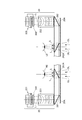
図1は、本発明を適用した実施形態に係る頭部装着型表示装置100(表示装置)の外観構成を示す説明図である。
頭部装着型表示装置100は、使用者の頭部に装着された状態で使用者に虚像を視認させる画像表示部20(表示部)と、画像表示部20を制御する制御装置10と、を備えている。制御装置10は、使用者が頭部装着型表示装置100を操作するコントローラーとしても機能する。
FIG. 1 is an explanatory diagram showing an external configuration of a head-mounted display device 100 (display device) according to an embodiment to which the present invention is applied.
The head-mounted
画像表示部20は、使用者の頭部に装着される装着体であり、本実施形態では眼鏡形状を有する。画像表示部20は、右保持部21と、右表示駆動部22と、左保持部23と、左表示駆動部24と、右光学像表示部26と、左光学像表示部28と、カメラ61(撮像部)と、マイク63とを備える。右光学像表示部26及び左光学像表示部28は、それぞれ、使用者が画像表示部20を装着した際に使用者の右及び左の眼前に位置するように配置されている。右光学像表示部26の一端と左光学像表示部28の一端とは、使用者が画像表示部20を装着した際の使用者の眉間に対応する位置で、互いに連結されている。
The
右保持部21は、右光学像表示部26の他端である端部ERから、使用者が画像表示部20を装着した際の使用者の側頭部に対応する位置にかけて、延伸して設けられた部材である。同様に、左保持部23は、左光学像表示部28の他端である端部ELから、使用者が画像表示部20を装着した際の使用者の側頭部に対応する位置にかけて、延伸して設けられた部材である。右保持部21及び左保持部23は、眼鏡のテンプル(つる)のようにして、使用者の頭部に画像表示部20を保持する。
The
右表示駆動部22と左表示駆動部24とは、使用者が画像表示部20を装着した際の使用者の頭部に対向する側に配置されている。なお、右表示駆動部22及び左表示駆動部24を総称して単に「表示駆動部」とも呼び、右光学像表示部26及び左光学像表示部28を総称して単に「光学像表示部」とも呼ぶ。
The right
表示駆動部22,24は、図2を参照して後述する液晶ディスプレイ241,242(Liquid Crystal Display、以下「LCD241,242」と呼ぶ)、投写光学系251,252等を含む。
右光学像表示部26及び左光学像表示部28は、導光板261,262(図2)と、調光板20Aとを備える。導光板261,262は、光透過性の樹脂等によって形成され、表示駆動部22,24が出力する画像光を、使用者の眼に導く。調光板20Aは、薄板状の光学素子であり、使用者の眼の側とは反対の側である画像表示部20の表側を覆うように配置される。調光板20Aは、光透過性がほぼ無いもの、透明に近いもの、光量を減衰させて光を透過するもの、特定の波長の光を減衰又は反射するもの等、種々のものを用いることができる。調光板20Aの光学特性(光透過率など)を適宜選択することにより、外部から右光学像表示部26及び左光学像表示部28に入射する外光量を調整して、虚像の視認のしやすさを調整できる。本実施形態では、少なくとも、頭部装着型表示装置100を装着した使用者が外の景色を視認できる程度の光透過性を有する調光板20Aを用いる場合について説明する。調光板20Aは、右導光板261及び左導光板262を保護し、右導光板261及び左導光板262の損傷や汚れの付着等を抑制する。
調光板20Aは、右光学像表示部26及び左光学像表示部28に対し着脱可能としてもよく、複数種類の調光板20Aを交換して装着可能としてもよいし、省略してもよい。
The
The right optical
The dimming
カメラ61は、右光学像表示部26と左光学像表示部28との境目部分に配置される。使用者が画像表示部20を装着した状態で、カメラ61の位置は、水平方向においては使用者の両眼のほぼ中間であり、鉛直方向においては使用者の両眼より上である。カメラ61は、CCDやCMOS等の撮像素子及び撮像レンズ等を備えるデジタルカメラであり、単眼カメラであってもステレオカメラであってもよい。
カメラ61は、頭部装着型表示装置100の表側方向、換言すれば、頭部装着型表示装置100を装着した状態における使用者の視界方向の少なくとも一部の外景を撮像する。カメラ61の画角の広さは適宜設定可能であるが、カメラ61の撮像範囲が、使用者が右光学像表示部26、左光学像表示部28を通して視認する外界を含む範囲であることが好ましい。さらに、調光板20Aを通した使用者の視界の全体を撮像できるようにカメラ61の撮像範囲が設定されているとより好ましい。
The
The
また、フレーム2には照度センサー68が配置される。照度センサー68は、外光の光量を検出して、検出値を出力する環境光センサー(Ambient Light Sensor)である。照度センサー68はカメラ61の近傍に配置され、カメラ61の画角を含む方向から照度センサー68に向けて照射される光を受光し、光量を検出する。
本実施形態では、一つの照度センサー68をフレーム2に設ける構成を例に挙げるが、複数の照度センサー68を設けることも可能である。また、照度センサー68の位置は、図1に示すようにフレーム2の幅方向における中央とする他、端部ERや端部ELに設けてもよい。
An
In the present embodiment, a configuration in which one
図2は、画像表示部20が備える光学系の構成を示す要部平面図である。図2には説明のため使用者の左眼LE及び右眼REを図示する。
左表示駆動部24は、LED等の光源と拡散板とを有する左バックライト222を備える。また、左表示駆動部24は、左バックライト222の拡散板で拡散された光の光路上に配置される透過型の左LCD242、および、左LCD242を透過した画像光Lを導くレンズ群等を備えた左投写光学系252を備える。左LCD242は、複数の画素をマトリクス状に配置した透過型液晶パネルである。
FIG. 2 is a principal plan view showing the configuration of the optical system provided in the
The left
左投写光学系252は、左LCD242から射出された画像光Lを平行状態の光束にするコリメートレンズを有する。コリメートレンズにより平行状態の光束にされた画像光Lは、左導光板262(光学素子)に入射される。左導光板262は、画像光Lを反射する複数の反射面が形成されたプリズムであり、画像光Lは、左導光板262の内部において複数回の反射を経て左眼LE側に導かれる。左導光板262には、左眼LEの眼前に位置するハーフミラー262A(反射面)が形成される。
ハーフミラー262Aで反射した画像光Lは左眼LEに向けて左光学像表示部28から射出され、この画像光Lが左眼LEの網膜に像を結び、使用者に画像を視認させる。
The left projection
The image light L reflected by the
右表示駆動部22は、左表示駆動部24と左右対称に構成される。右表示駆動部22は、LED等の光源と拡散板とを有する右バックライト221を備える。また、右表示駆動部22は、右バックライト221の拡散板で拡散された光の光路上に配置される透過型の右LCD241、および、右LCD241を透過した画像光Lを導くレンズ群等を備えた右投写光学系251を備える。右LCD241は、複数の画素をマトリクス状に配置した透過型液晶パネルである。
The right
右投写光学系251は、右LCD241から射出された画像光Lを平行状態の光束にするコリメートレンズを有する。コリメートレンズにより平行状態の光束にされた画像光Lは、右導光板261(光学素子)に入射される。右導光板261は、画像光Lを反射する複数の反射面が形成されたプリズムであり、画像光Lは、右導光板261の内部において複数回の反射を経て右眼RE側に導かれる。右導光板261には、右眼REの眼前に位置するハーフミラー261A(反射面)が形成される。
ハーフミラー261Aで反射した画像光Lは右眼REに向けて右光学像表示部26から射出され、この画像光Lが右眼REの網膜に像を結び、使用者に画像を視認させる。
The right projection
The image light L reflected by the
使用者の右眼REには、ハーフミラー261Aで反射した画像光Lと、調光板20Aを透過した外光OLとが入射する。左眼LEには、ハーフミラー262Aで反射した画像光Lと、調光板20Aを透過した外光OLとが入射する。このように、頭部装着型表示装置100は、内部で処理した画像の画像光Lと外光OLとを重ねて使用者の眼に入射させ、使用者にとっては、調光板20Aを透かして外景が見え、この外景に重ねて、画像光Lによる画像が視認される。このように、頭部装着型表示装置100は、シースルー型の表示装置として機能する。
The image light L reflected by the
なお、左投写光学系252と左導光板262とを総称して「左導光部」とも呼び、右投写光学系251と右導光板261とを総称して「右導光部」と呼ぶ。右導光部及び左導光部の構成は上記の例に限定されず、画像光を用いて使用者の眼前に虚像を形成する限りにおいて任意の方式を用いることができ、例えば、回折格子を用いても良いし、半透過反射膜を用いても良い。
The left projection
また、照度センサー68は、使用者が右導光板261、左導光板262を透過して使用者が視認する外景方向の外光を検出する。即ち、図2の外光OLを受光するように、フレーム2に取り付けられる。つまり、照度センサー68は、画像光Lの背景光として使用者の眼に入射する外光OLを検出する。
In addition, the
画像表示部20(図1)は、制御装置10に接続部40を介して接続する。接続部40は、制御装置10に接続される本体コード48、右コード42、左コード44、及び、連結部材46を備えるハーネスである。右コード42及び左コード44は、本体コード48が2本に分岐し、右コード42は右保持部21の延伸方向の先端部APから右保持部21の筐体内に挿入され、右表示駆動部22に接続される。同様に、左コード44は、左保持部23の延伸方向の先端部APから左保持部23の筐体内に挿入され、左表示駆動部24に接続される。右コード42、左コード44、及び、本体コード48は、デジタルデータを伝送可能なものであればよく、例えば金属ケーブルや光ファイバーで構成できる。また、右コード42と左コード44とを一本のコードにまとめた構成としてもよい。
The image display unit 20 (FIG. 1) is connected to the
連結部材46は、本体コード48と、右コード42及び左コード44との分岐点に設けられ、イヤホンプラグ30を接続するためのジャックを有する。イヤホンプラグ30からは、右イヤホン32及び左イヤホン34が延伸する。イヤホンプラグ30の近傍にはマイク63が設けられる。イヤホンプラグ30からマイク63までは一本のコードにまとめられ、マイク63からコードが分岐して、右イヤホン32と左イヤホン34のそれぞれに繋がる。
The connecting
マイク63は、例えば図1に示すように、マイク63の集音部が使用者の視線方向を向くように配置され、音声を集音して、音声信号を出力する。マイク63は、例えばモノラルマイクであってもステレオマイクであってもよく、指向性を有するマイクであってもよいし、無指向性のマイクであってもよい。
For example, as shown in FIG. 1, the
画像表示部20と制御装置10とは、接続部40を介して各種信号を伝送する。本体コード48の連結部材46とは反対側の端部、及び、制御装置10には、互いに嵌合するコネクター(図示略)が設けられる。本体コード48のコネクターと制御装置10のコネクターとを嵌合し、或いは、この嵌合を外すことで、制御装置10と画像表示部20とを接離できる。
The
制御装置10は、画像表示部20の本体とは別体となる箱形の本体を有し、頭部装着型表示装置100を制御する。制御装置10は、決定キー11、点灯部12、表示切替キー13、輝度切替キー15、方向キー16、メニューキー17、及び電源スイッチ18を含むスイッチ類を備える。また、制御装置10は、使用者が手指で操作するトラックパッド14を備える。
The
決定キー11は、押下操作を検出して、制御装置10で操作された内容を決定する信号を出力する。点灯部12は、LED(Light Emitting Diode)等の光源を備え、光源の点灯状態により、頭部装着型表示装置100の動作状態(例えば、電源のON/OFF)を通知する。表示切替キー13は、押下操作に応じて、例えば、画像の表示モードの切り替えを指示する信号を出力する。
The
トラックパッド14は、接触操作を検出する操作面を有し、操作面に対する操作に応じて操作信号を出力する。操作面における検出方式は限定されず、静電式、圧力検出式、光学式等を採用できる。輝度切替キー15は、押下操作に応じて画像表示部20の輝度の増減を指示する信号を出力する。方向キー16は、上下左右方向に対応するキーへの押下操作に応じて操作信号を出力する。電源スイッチ18は、頭部装着型表示装置100の電源オン/オフを切り替えるスイッチである。
The
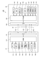
図3は、頭部装着型表示装置100を構成する各部の機能ブロック図である。
制御装置10は、制御装置10及び画像表示部20を制御する制御部110(第2制御部)を備える。制御部110は、例えばマイクロプロセッサーで構成され、制御部110が処理するデータ等を一時的に記憶するメモリー121、及び、制御部110が処理するデータ等を不揮発的に記憶するフラッシュメモリー122に接続される。メモリー121及びフラッシュメモリー122はいずれも半導体素子により構成され、データバスを介して制御部110に接続する。
FIG. 3 is a functional block diagram of each part constituting the head-mounted
The
制御部110には、電源制御部123、UI(ユーザーインターフェイス)制御部124、無線I/F(インターフェイス)制御部125、音声制御部126、センサーIC127、及び、外部I/F(インターフェイス)部128が接続される。
頭部装着型表示装置100は、電源として一次電池または二次電池を備え、電源制御部123は、これら電池に接続されるICで構成される。電源制御部123は、制御部110の制御に従って電池の残容量の検出を行い、検出値のデータ、または残容量が設定値以下となったことを示すデータを制御部110に出力する。
The
The head-mounted
UI制御部124は、図1に示した決定キー11、表示切替キー13、トラックパッド14、輝度切替キー15、方向キー16、及びメニューキー17の各操作部、点灯部12、及び、トラックパッド14が接続されるICである。上記各操作部は入力部として機能し、点灯部12及びトラックパッド14は出力部として機能し、頭部装着型表示装置100のユーザーインターフェイスを構成する。UI制御部124は、上記操作部における操作を検出して、操作に対応する操作データを制御部110に出力する。また、UI制御部124は、制御部110の制御に従って、点灯部12の点灯/消灯、及びトラックパッド14における表示を行う。
The
無線I/F制御部125は、無線通信インターフェイス(図示略)に接続される制御ICであり、制御部110の制御に従って、上記無線通信インターフェイスによる通信を実行する。制御装置10が備える無線通信インターフェイスは、例えば、無線LAN(WiFi(登録商標))、Miracast(登録商標)、Bluetooth(登録商標)等の規格に準じた無線データ通信を実行する。
音声制御部126は、右イヤホン32、左イヤホン34、及びマイク63に接続され、A/D(アナログ/ディジタル)コンバーターやアンプ等を備えるICである。音声制御部126は、制御部110から入力される音声データに基づき右イヤホン32及び左イヤホン34から音声を出力させる。また、音声制御部126は、マイク63が集音する音声に基づき音声データを生成して制御部110に出力する。
The wireless I /
The
センサーIC127は、例えば、3軸加速度センサー、3軸ジャイロセンサー、及び3軸地磁気センサーを備え、例えば上記センサーを具備する1つのICで構成される。センサーIC127は、制御部110の制御に従って検出を実行し、各センサーの検出値を示すデータを制御部110に出力する。センサーIC127が備えるセンサーの数や種類は制限されず、照度センサー、温度センサー、圧力センサー等を備えてもよい。
The
外部I/F部128は、頭部装着型表示装置100を外部機器に接続するインターフェイスである。例えば、USBインターフェイス、マイクロUSBインターフェイス、メモリーカード用インターフェイス等の有線接続に対応したインターフェイスを用いることができ、無線通信インターフェイスで構成してもよい。外部I/F部128には、頭部装着型表示装置100に対してコンテンツを供給する種々の外部機器を接続できる。これらの外部機器は、頭部装着型表示装置100に画像を供給する画像供給装置ということもでき、例えば、パーソナルコンピューター(PC)、携帯電話端末、携帯型ゲーム機等が用いられる。また、外部I/F部128は、右イヤホン32、左イヤホン34及びマイク63に繋がる端子を設けてもよく、この場合、音声制御部126が処理するアナログ音声信号は外部I/F部128を介して入出力される。
The external I /
制御部110には、I/F(インターフェイス)部115が接続される。I/F部115は接続部40に一端に接続するコネクター等を備えたインターフェイスであり、接続部40の他端は画像表示部20のI/F部155に接続される。
制御部110は、接続部40を介して、画像表示部20が備えるサブ制御部150とデータ通信を実行する。
An I / F (interface)
The
制御部110は、内蔵するROMに記憶するプログラムを実行して、頭部装着型表示装置100の各部を制御する。制御部110は、センサーIC127から入力されるデータに基づきセンサーの検出値を取得して、メモリー121に記憶する。このとき、制御部110は、センサーの検出値に対応付けて、検出値を取得した時刻を示すタイムスタンプ情報を付加して記憶する。
The
また、制御部110は、接続部40を介して、画像表示部20が備えるセンサー(照度センサー68、9軸センサー162、及び、GPS163)の検出値を示すデータを受信する。制御部110は、受信したデータをメモリー121に記憶する。制御部110が受信するデータは、サブ制御部150が付加したタイムスタンプ情報を含む。制御部110は、上記のようにセンサーIC127の検出値に付加するタイムスタンプ情報を、サブ制御部150が付加したタイムスタンプ情報と区別できる態様で付加し、メモリー121に記憶する。メモリー121には、センサーの検出値が、データの属性の1つとしてタイムスタンプ情報が付加されたデータ形式で記憶される。ここで、制御部110は、センサーの検出値のデータを、フラッシュメモリー122に記憶してもよい。
Further, the
制御部110は、外部I/F部128または無線I/F制御部125により接続する外部機器から、コンテンツのデータを受信して、フラッシュメモリー122に記憶する。コンテンツのデータは、画像表示部20で表示するテキストや画像等のデータであり、右イヤホン32及び左イヤホン34で出力する音声のデータを含んでもよい。制御部110は、頭部装着型表示装置100を制御してコンテンツを再生する。具体的には、制御部110は、コンテンツの表示用のデータをサブ制御部150に送信して表示を実行させ、コンテンツの音声データを音声制御部126に出力して音声を出力させる。また、外部機器から受信するコンテンツのデータが、再生に関する条件を示すデータを含む場合、制御部110は、この条件に従ってコンテンツを再生する。例えば、画像表示部20において検出される位置や傾き等のセンサーの検出値が、条件に該当する場合に、検出値に対応するテキストや画像を表示させる。
The
画像表示部20は、制御部110と通信を実行し、画像表示部20の各部を制御するサブ制御部150を備える。サブ制御部150は、例えばマイクロプロセッサーで構成され、I/F部155により接続部40に接続され、接続部40を介して制御部110との間でデータ通信を実行する。
サブ制御部150には、照度センサー68、9軸センサー162、及び、GPS163のセンサー類が接続される。照度センサー68は、上述したように環境光センサー(ALS)のIC、又は、環境光センサーを含む複数のセンサーやセンサーの周辺回路をユニット化したICである。9軸センサー162は、3軸加速度センサー、3軸ジャイロセンサー、及び、3軸地磁気センサーを備えるICである。
照度センサー68は、サブ制御部150の制御により駆動され、光量の検出値をサブ制御部150に出力する。また、9軸センサー162は、サブ制御部150の制御により駆動され、内蔵する各センサーの検出値を示すデータを、サブ制御部150に出力する。
The
The
The
GPS163は、GPS衛星や屋内に設置される疑似GPS送信機(図示略)が送信する位置検出用の信号を受信して、画像表示部20の現在位置を算出し、算出したデータをサブ制御部150に出力する。GPS163は、位置検出用の信号を受信する受信機としての機能のみ有する構成としてもよく、この場合、GPS163が出力するデータに基づきサブ制御部150が現在位置を算出する処理を行えば良い。
The
EEPROM165(設定データ記憶部)は、サブ制御部150が実行する処理に関するデータ等を不揮発的に記憶する。
また、サブ制御部150にはカメラ61が接続され、サブ制御部150は、カメラ61を制御して撮像を実行させ、カメラ61の撮像画像データを制御部110に送信する。
The EEPROM 165 (setting data storage unit) stores data related to processing executed by the
In addition, the
サブ制御部150には、右LCD241を駆動して描画を行うLCD駆動部167、及び、左LCD242を駆動して描画を行うLCD駆動部168が接続される。サブ制御部150は、制御部110からコンテンツのデータを受信し、受信したデータに含まれるテキストや画像を表示する表示データを生成してLCD駆動部167、168に出力し、表示を実行させる。
Connected to the
また、サブ制御部150は、右バックライト221を駆動するバックライト駆動部169、及び、左バックライト222を駆動するバックライト駆動部170に接続される。サブ制御部150は、バックライト駆動部169、170に対し、PWM制御用のタイミングデータを含む制御データを出力する。バックライト駆動部169、170は、サブ制御部150から入力される制御データに基づき、右バックライト221、左バックライト222に駆動電圧とパルスを供給して、右バックライト221、左バックライト222を点灯させる。
The
また、サブ制御部150は、バックライト駆動部169に出力するデータにより、バックライト駆動部169が右バックライト221に出力するパルスのパルス幅、或いは、デューティーを指定する。デューティーは、パルスのオン期間とオフ期間の比を指す。同様に、サブ制御部150は、バックライト駆動部170に出力するデータにより、バックライト駆動部170が左バックライト222に出力するパルスのパルス幅、或いは、デューティーを指定する。右バックライト221及び左バックライト222はLED等の個体光源であり、発光する明るさ、すなわち輝度をPWM制御により調整できる。従って、サブ制御部150の制御により、使用者の眼に入射する画像光L(図2)の光量を調整できる。また、サブ制御部150はバックライト駆動部169とバックライト駆動部170のそれぞれに、異なるデータを出力し、右バックライト221の輝度と左バックライト222の輝度とを個別に調整できる。
Further, the
バックライト駆動部169は、右バックライト221の輝度を段階的に調整でき、バックライト駆動部170も同様に、左バックライト222の輝度を段階的に調整できる。本実施形態では、輝度を256段階で調整可能な構成を例に挙げる。サブ制御部150は、バックライト駆動部169、170に対し、右バックライト221及び左バックライト222のそれぞれの輝度を指定するデータを出力する。このデータは、輝度の段階を示す0〜255の輝度値である。バックライト駆動部169、170は、サブ制御部150から入力するデータで指定された輝度値に対応するパルスを生成して、右バックライト221と左バックライト222のそれぞれに出力する。
サブ制御部150には、表示に適した輝度や、右LCD241及び左LCD242のガンマ値等を加味して設定された輝度値が、初期値として設定される。
The
In the
制御部110とサブ制御部150とを接続する接続部40は、制御データバス41A、画像データバス41B、表示データバス41C、41Dを含む複数のデータバスを有する。これらのデータバスは、互いに独立してデータを伝送可能であるが、各データバスを構成する信号線が物理的に区分された構成であってもよいし、各データバスが共通の信号線を用いて仮想的あるいは論理的に構成されてもよい。
制御データバス41Aは、制御部110からサブ制御部150に対して送信される制御データ、サブ制御部150が制御部110に送信するセンサーの検出値のデータ等を伝送する。画像データバス41Bは、サブ制御部150から制御部110に、カメラ61の撮像画像データを伝送する。表示データバス41Cは、右表示駆動部22で表示するデータを伝送し、表示データバス41Dは左表示駆動部24で表示するデータを伝送する。
The
The
画像表示部20が備える照度センサー68、9軸センサー162、及び、GPS163を含む複数のセンサーのサンプリング周期は、大きく異なることもある。例えば、9軸センサー162の加速度センサーのサンプリング周期(サンプリング頻度)は200回/秒以上となることが考えられる。これに対し、照度センサー68のサンプリング周期はより遅く、1〜10回/秒(1000〜100ms周期)程度でも十分に役立つことが考えられる。これらのセンサーは、サブ制御部150がサンプリング周期の設定を行い、設定したサンプリング周期に従ってサブ制御部150が検出値を取得する。サブ制御部150は、各センサーからサンプリングした検出値のデータを、制御データバス41Aにおいて時分割で制御部110に送信する。
The sampling periods of a plurality of sensors including the
このため、サンプリング周期の遅い(サンプリング頻度が低い、或いは、サンプリング間隔が長いと言い換えられる)センサーを制御するために制御データバス41Aが長時間占有されることがない。これにより、制御データバス41Aのオーバーヘッドを低減し、制御データバス41Aで多数のセンサーの検出値を効率よく伝送できる。また、サブ制御部150は、RAM(図示略)を内蔵し、センサーの検出値を取得した場合はRAMに一時的に記憶する。サブ制御部150は、RAMに記憶したデータの送信タイミングを調整して、データを制御データバス41Aに送出する。従って、サブ制御部150の動作も、各センサーのサンプリング周期の制約を受けにくく、センサーの制御のためにサブ制御部150の処理が占有される事態を防止できる。
For this reason, the
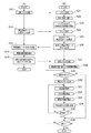
図4は、頭部装着型表示装置100の動作を示すフローチャートであり、(A)は制御装置10の動作を示し、(B)は画像表示部20の動作を示す。
制御装置10に対する操作により、表示動作の開始が指示されると、制御部110が、起動コマンドを生成してサブ制御部150に送信する(ステップS11)。このコマンドは制御データバス41Aを介して伝送され、サブ制御部150はコマンドを受信する(ステップS21)。
FIG. 4 is a flowchart showing the operation of the head-mounted
When the start of the display operation is instructed by an operation on the
サブ制御部150は動作を開始し、コマンドに従って、サブ制御部150の初期化を行い、照度センサー68、9軸センサー162、及びGPS163を含む画像表示部20の各部の初期化を行う(ステップS22)。続いて、サブ制御部150は、バックライト駆動部169、170を動作させて右バックライト221及び左バックライト222を点灯させる(ステップS23)。ステップS23で、サブ制御部150は、バックライト駆動部169、170に対するPWM制御用のデータとして、初期値のデータを出力する。また、サブ制御部150は、必要に応じてカメラ61、9軸センサー162、GPS163等を起動させる。
The
続いて、制御部110が、輝度調整用のデータの取得を指示するコマンドを生成して、サブ制御部150に送信する(ステップS12)。
サブ制御部150は、制御部110が送信するコマンドを受信し(ステップS24)、受信したコマンドに従って、EEPROM165から、輝度調整用のデータである輝度調整データを読み出し、取得する(ステップS25)。サブ制御部150は、取得した輝度調整データを制御部110に送信し(ステップS26)、制御部110は、サブ制御部150が送信する輝度調整データを受信する(ステップS13)。
Subsequently, the
The
輝度調整データは、右バックライト221と左バックライト222の輝度を調整する初期値である。例えば、右バックライト221及び左バックライト222のそれぞれが備えるLED等の光源の個体差により、右バックライト221と左バックライト222の輝度のばらつきを生じることがある。この場合、バックライト駆動部169、170が同じパルスを右バックライト221と左バックライト222とに出力すると、使用者の右眼に入射する画像光Lの光量と、左眼に入射する画像光Lの光量とが揃わず、違和感を生む可能性がある。輝度調整データは、使用者に、右光学像表示部26と左光学像表示部28の表示輝度のばらつきを感じさせないように、右バックライト221の輝度と左バックライト222の輝度とを揃えるためのデータである。輝度調整データは、予め設定されてEEPROM165に記憶される。例えば、頭部装着型表示装置100の出荷時の検査により、輝度調整データが求められ、EEPROM165に記憶される。
The brightness adjustment data is an initial value for adjusting the brightness of the
制御部110は、サブ制御部150から受信した輝度調整データに基づき、輝度の設定値を算出する(ステップS14)。続いて、制御部110は、輝度の設定値を指定する設定コマンドと、算出した輝度の設定値を示すデータとを、サブ制御部150に送信する(ステップS15)。ステップS14で制御部110が算出する設定値は、サブ制御部150がバックライト駆動部169、170に出力するデータのもととなる値である。右バックライト221及び左バックライト222の初期値(デフォルト値)である輝度に、左右の輝度の差を感じさせないようにする補正を加えた値である。
The
サブ制御部150は、制御部110から送信される設定コマンドとデータを受信し(ステップS27)、受信した設定値に従って、右バックライト221及び左バックライト222のPWM制御を開始する(ステップS28)。すなわち、サブ制御部150は、PWM制御用のデータを生成し、バックライト駆動部169、170に出力し、右バックライト221及び左バックライト222の輝度を調整する。
The
さらに、サブ制御部150は、自動調光を行うか否かを判定する(ステップS29)。自動調光とは、頭部装着型表示装置100の外部の明るさに対応して、右光学像表示部26及び左光学像表示部28の表示の明るさを調整する処理である。自動調光を行うか否かは、予め設定され、設定状態を示すデータが、例えばフラッシュメモリー122またはEEPROM165に記憶される。
Further, the
自動調光を行う場合(ステップS29;YES)、サブ制御部150は、照度センサー68を起動させ、光量の検出を開始させる(ステップS30)。次いで、サブ制御部150は、照度センサー68の検出値を取得し(ステップS31)、取得した照度センサー68の検出値に基づき調光指数(補正係数)を算出する(ステップS32)。
When performing automatic light control (step S29; YES), the
調光指数は、例えば下記式(1)で示す演算により求めることができる。
X=A×Q^B+C ・・・(1)
但し、Xは調光指数であり、A、B及びCは定数である。Qは照度センサー68の検出値から求められる平均環境照度(単位は[lux])である。
上記式(1)及び定数A、B、Cは、例えば予めEEPROM165に記憶される。
定数A、B、Cは、例えば平均環境照度Qが、平均的な室内環境である400luxまたはその近傍である場合に、調光指数X=1となるように定められる。例えば、0<A≦1、0<B≦1、0≦C≦1である。
The dimming index can be obtained, for example, by calculation represented by the following formula (1).
X = A × Q ^ B + C (1)
However, X is a dimming index and A, B, and C are constants. Q is the average environmental illuminance (unit: [lux]) obtained from the detection value of the
The above equation (1) and the constants A, B, and C are stored in advance in the
The constants A, B, and C are determined so that, for example, the dimming index X = 1 when the average ambient illuminance Q is 400 lux, which is an average indoor environment, or the vicinity thereof. For example, 0 <A ≦ 1, 0 <B ≦ 1, and 0 ≦ C ≦ 1.
サブ制御部150は、照度センサー68の検出値をそのまま平均環境照度Qの値として上記式(1)の演算を行ってもよいし、予め設定された期間内で照度センサー68から複数回の検出値を取得し、取得した検出値の平均を平均環境照度Qの値としてもよい。また、照度センサー68の検出値またはその平均値を、予め設定された演算処理により、平均環境照度Qに変換してもよい。
The
さらに、サブ制御部150は、照度センサー68の検出値についてノイズフィルタリングを行って、平均環境照度Qを求めてもよい。例えば、照度センサー68の検出値を取得する時間の長さが、照度取得時間(単位は[秒])として予め設定され、サブ制御部150は照度取得時間に所定のサンプリング周期で検出値(照度)を取得する。サブ制御部150は取得した検出値のうち最も大きい所定個の値と、最も小さい所定個の値とを除いて平均し、平均環境照度を算出する。検出値からトリミングする値の数は、予め設定され、或いは制御部110が設定コマンドでサブ制御部150に設定する。
Further, the
続いて、サブ制御部150は輝度調整値を求める(ステップS33)。輝度調整値は、調光制御の前に、サブ制御部150がバックライト駆動部169、170に設定する輝度値を、調光指数Xで補正した値である。輝度調整値は、例えば下記式(2)で示す演算により求めることができる。
輝度調整値=輝度値×調光指数X ・・・(2)
Subsequently, the
Luminance adjustment value = Luminance value x Dimming index X (2)
輝度値は、EEPROM165に記憶された輝度調整データに基づき、ステップS14で制御部110が算出する輝度値であり、右バックライト221、左バックライト222の個体差等を加味した値であるが、照度センサー68の検出値は反映されていない。例えば、輝度値は、制御部110がステップS15で送信する設定コマンドにより、サブ制御部150のレジスターに書き込まれる。サブ制御部150は、輝度値に対して調光指数を乗算することで、外光の輝度、言い換えれば環境照度に対応して、バックライト駆動部169、170に出力する輝度値のデータを変更する。具体的には、レジスターに書き込まれた輝度値の値を、上記式(2)で求められる輝度調整値に更新する。後述するように調光処理をループで実行する場合は、レジスターに書き込まれた輝度調整値を更新する。
輝度調整値については上記式(2)で求められる値をそのまま用いてもよいが、調整を行ってもよい。例えば、調光指数を乗じる前の輝度値が0でない場合は、輝度調整値の最小値を1とし、上記式(2)で求められた値を補正してもよい。
The luminance value is a luminance value calculated by the
As the brightness adjustment value, the value obtained by the above equation (2) may be used as it is, but adjustment may be performed. For example, when the luminance value before being multiplied by the dimming index is not 0, the minimum value of the luminance adjustment value may be set to 1, and the value obtained by the above equation (2) may be corrected.
上記式(1)で補正係数を演算処理により求める場合に、所定の補正曲線に基づき照度センサー68の検出値を補正係数に変換してもよく、この場合に、補正曲線がシーン毎に異なるよう設定されてもよい。この場合、例えば制御装置10に対する使用者の操作によりシーンが選択され、選択されたシーンに対応する補正曲線、すなわち上記式(1)に相当する関数により、補正係数が求められる。また、照度センサー68の検出値や、検出値の経時変化に基づき、シーンを自動的にサブ制御部150が判定してもよい。
When the correction coefficient is calculated by the above formula (1), the detection value of the
具体的なシーンとしては、例えば、次のシーンが挙げられる。
[1]低照度環境下でも、右光学像表示部26及び左光学像表示部28が表示する画像や映像と、外景とを見易くする「低照度環境モード」。
[2]リビングルームなど明るい室内において、右光学像表示部26及び左光学像表示部28が表示するテキスト、画像、映像等と、外景とを見易くし、例えば業務のドキュメント等の表示に適した「外界、映像両立モード」。
[3]右光学像表示部26及び左光学像表示部28が表示する画像や映像の視認性を高くする一方、外景の視認性を低下させて、例えば映画の視聴に適した「シアター鑑賞モード」。
[4]晴天の屋外など明るい環境下において、右光学像表示部26及び左光学像表示部28が表示するテキストや画像の視認性を確保し、例えば真夏の炎天下で作業指示等のマュアルを読めるようにした「青天下ドキュメント閲覧モード」。
Specific examples of the scene include the following scene.
[1] “Low illuminance environment mode” that makes it easy to see the images and videos displayed by the right optical
[2] In a bright room such as a living room, the text, images, video, and the like displayed by the right optical
[3] “Theater viewing mode” suitable for viewing movies, for example, by increasing the visibility of images and videos displayed by the right optical
[4] The visibility of text and images displayed by the right optical
また、サブ制御部150は、上記式(1)に示した演算処理に代えて、照度センサー68の検出値と調光指数とを対応付けるLUT(LookUpTable)を用いて、調光指数を求めてもよい。このLUTが照度センサー68の代表値について調光指数を設定するLUTである場合には、照度センサー68の検出値に対応する調光指数を、補間演算により求めてもよい。さらに、サブ制御部150は、上記式(2)に示した演算処理に代えて、調光指数と、現在設定されている輝度値とをもとに輝度調整値を求めるLUTを用い、輝度調整値を求めてもよい。このLUTが代表値を含む構成である場合に、サブ制御部150は補間演算を行ってもよい。これらのLUTは、例えば、EEPROM165、或いは、フラッシュメモリー122に予め記憶されていてもよい。
Further, the
また、[1]〜[4]に例示したシーンに対応して、シーン毎に予めLUTが記憶され、サブ制御部150がシーンに対応したLUTを選択して、補正係数を求めてもよい。
In addition, an LUT may be stored in advance for each scene corresponding to the scenes illustrated in [1] to [4], and the
すなわち、サブ制御部150は、バックライト駆動部169、170に出力するデータを、ステップS33で求めた輝度調整値のデータに更新する(ステップS34)。これにより、バックライト駆動部169、170が右バックライト221及び左バックライト222のそれぞれに出力するパルスが、輝度調整値に対応するパルスに変更される。
That is, the
その後、サブ制御部150は、調光処理を終了するか否かを判定する(ステップS35)。調光処理を終了しないと判定した場合(ステップS35;NO)、サブ制御部150はステップS31に戻る。これにより、調光処理のループが継続され、照度センサー68の検出値を反映して、右バックライト221、左バックライト222の輝度が随時調整される。
Thereafter, the
また、制御装置10の操作により調光処理の終了が指示された場合や、右バックライト221及び左バックライト222の輝度が手動操作により設定された場合、サブ制御部150は調光処理を終了すると判定する(ステップS35;YES)。この場合、サブ制御部150は、表示処理を終了するか否かを判定する(ステップS36)。表示処理を終了しない場合は(ステップS36;NO)、ステップS29に戻る。また、制御装置10の操作により表示処理の終了が指示された場合や、制御装置10の電源スイッチ18により頭部装着型表示装置100がオフにされた場合、サブ制御部150は表示処理を終了すると判定し、停止する(ステップS36;YES)。
Further, when the end of the dimming process is instructed by the operation of the
このように、照度センサー68が検出する環境照度に対応して、右導光板261、左導光板262から使用者の眼に入射する画像光Lを調整するので、画像表示部20が表示する画像の視認性を良好に保つことができる。シースルーのハーフミラー261A、262Aで表示される画像は、外光OLの強さ、光量により、視認性が影響されるが、図4の動作をサブ制御部150が行うことで、環境照度の変化に対しリアルタイムに、シームレスに対応できる。
As described above, the image light L that is incident on the user's eyes from the right
なお、ステップS31で取得した照度の検出値により、ステップS34で輝度値または輝度調整値を更新する場合、急激な輝度の変化を軽減するため、指定回数分、中間ステップを挿入してもよい。この場合、輝度調整値を変更(更新)する際に、右バックライト221及び左バックライト222の輝度を、変更前の輝度調整値から変更後の輝度調整値に変化させる間、1または複数の中間ステップの輝度が設定される。これにより、右バックライト221及び左バックライト222の輝度が段階的に変化する。
サブ制御部150には、輝度値が低い状態から高くする場合の中間ステップの回数として、明順応回数が設定され、輝度値が高い状態から低くする場合の中間ステップの回数として、暗順応回数が設定される。また、中間ステップを行う時間としてディミング時間が設定される。
When the luminance value or the luminance adjustment value is updated in step S34 based on the detected illuminance value acquired in step S31, intermediate steps may be inserted for the specified number of times in order to reduce a sudden change in luminance. In this case, when changing (updating) the luminance adjustment value, while changing the luminance of the
In the
例えば、ステップS32で求めた調光指数が第1の値P1であり、それ以前に求められた調光指数が第2の値P2である場合(但し、P2<P1)、ディミング時間毎に、下記式(3)で示す中間値だけ輝度値が変化する。
中間値=(P1−P2)/明順応回数 ・・・(3)
また、P1<P2の場合は、ディミング時間毎に、下記式(4)で示す中間値だけ輝度値が変化する。
中間値=(P2−P1)/暗順応回数 ・・・(4)
この処理により、照度センサー68が検出する環境照度が急激に変化しても、使用者の眼に入射する画像光Lの光量の変化が緩和されるので、使用感を損なわない。
For example, when the dimming index obtained in step S32 is the first value P1 and the dimming index obtained before that is the second value P2 (where P2 <P1), for each dimming time, The luminance value changes by an intermediate value represented by the following formula (3).
Intermediate value = (P1-P2) / number of light adaptations (3)
In the case of P1 <P2, the luminance value changes by an intermediate value represented by the following formula (4) every dimming time.
Intermediate value = (P2−P1) / number of dark adaptations (4)
By this processing, even if the environmental illuminance detected by the
上記式(3)及び(4)に示したように、頭部装着型表示装置100では、明順応と暗順応のそれぞれについて、独立して中間ステップの回数(明順応回数、暗順応回数)が設定される。また、ディミング時間も明順応と暗順応のそれぞれについて設定してもよい。従って、サブ制御部150が表示の輝度を明るく変化させる場合には、明順応について設定された中間ステップの回数及びディミング時間に従って処理が行われる。表示の輝度を暗く変化させる場合には、暗順応について設定された中間ステップの回数及びディミング時間に従って処理が行われる。
As shown in the above formulas (3) and (4), in the head-mounted
このように、明順応及び暗順応のいずれについても輝度の変化についてヒステリシスの設定ができる。従って、例えば使用者の周囲の明るさが大きく変化する場合に、表示の輝度を適切に変化させることで、外景の視認性の低下を抑制し、視認性を確保できる。外景がシースルーで視認できる頭部装着型表示装置100においては、使用者の安心感を高めることができ、効果的である。また、頭部装着型表示装置100を装着した状態で移動する使用方法においては特に効果的である。
さらに、明順応と暗順応のそれぞれに独立してヒステリシスの設定ができるので、より適切に、輝度の変化を設定できるという利点がある。
In this way, hysteresis can be set for changes in luminance for both light adaptation and dark adaptation. Therefore, for example, when the brightness of the surroundings of the user greatly changes, by appropriately changing the display brightness, it is possible to suppress a decrease in the visibility of the outside scene and ensure the visibility. In the head-mounted
Furthermore, since hysteresis can be set independently for each of light adaptation and dark adaptation, there is an advantage that a change in luminance can be set more appropriately.
また、サブ制御部150は、照度センサー68、9軸センサー162、及びGPS163等のセンサーを制御して検出値を取得し、制御部110に送信する。このため、制御部110が各センサーを制御する場合に比べて、制御部110の処理負荷、制御部110の処理の占有時間を大幅に軽減できる。また、制御部110に各センサーを接続した場合、サンプリング周期が異なるセンサーの検出値を同じ信号線で伝送することは困難であるから、接続部40に設ける信号線の数がセンサーの数に対応して多くなる。このため、接続部40のハーネスが太くなり取り回しが低下する、センサーの数が制限される等の好ましくない事態が懸念される。本実施形態のように、サブ制御部150が各センサーの検出値を取得し、制御データバス41Aを介した送信タイミングの調整を行い、複数のセンサーの検出値を送信することで、上記の事態を全て防止でき、効率のよい処理を実現できる。例えば、サブ制御部150は、サンプリング周期が短いセンサーの検出値を送信する動作を、予め設定したタイミングで優先的に行い、この動作の空き時間に、サンプリング周期の長いセンサーの検出値を送信してもよい。
そして、照度センサー68が検出する環境照度に対応して、サブ制御部150が、ステップS30〜S34の調光処理を実行するので、制御部110の負荷を増やすことなく、また、接続部40で伝送されるデータ量を増やさずに調光を行える。
Further, the
And since the
以上説明したように、本発明を適用した実施形態の頭部装着型表示装置100は、使用者の頭部に装着され、使用者の眼に画像光を照射する画像表示部20と、光を検出する照度センサー68とを備える。頭部装着型表示装置100は、サブ制御部150を備える。サブ制御部150は、制御部110が設定する輝度値に従い、画像表示部20の表示の輝度を調整する調整処理を行う。また、サブ制御部150は、照度センサー68の検出値に基づいて調光指数を求め画像表示部20の表示の輝度を補正する調光処理(補正処理)を実行する。このため、表示の輝度を調整する処理と、照度センサー68の検出値に基づき表示の輝度を変化させる処理とを容易に実行できるので、負荷の軽い処理により表示の輝度を適切に調整できる。
As described above, the head-mounted
サブ制御部150は、照度センサー68の検出値を、例えば上記式(1)のように予め設定された演算式に適用することにより、補正係数を求めるので、表示の輝度を変化させる処理を容易に実行できる。また、サブ制御部150は、LUTを使用して、照度センサー68の検出値に対応する補正係数を求めてもよい。
また、サブ制御部150は、調光処理により、ステップS28で設定した右バックライト221及び左バックライト222の輝度値に調光指数を乗じて、画像表示部20の表示の輝度値を補正する。このため、調整がなされた表示の輝度に対して照度センサー68の検出値を反映させて調整できる。
The
Further, the
また、サブ制御部は、画像表示部20の表示の輝度値を補正した輝度値に変化させる場合にヒステリシス処理を実行する。画像表示部20の表示の輝度値を高輝度側に変化させる場合と、輝度値を低輝度側に変化させる場合とのそれぞれについて、独立して前記ヒステリシス処理の条件を設定可能である。このため、照度センサー68の検出値が変化した場合に、使用者にとっての視認性を良好に維持できる。また、画像表示部20の輝度値を明るくする場合と暗くする場合とについて独立してヒステリシスの設定を行えるので、人間の眼の特性に合わせて、或いは、使用者の好みや表示装置の使用環境に合わせてヒステリシスの設定を行うことができる。
Further, the sub-control unit executes a hysteresis process when changing the display luminance value of the
また、画像表示部20は、使用者の右眼に画像光を照射する右眼用画像表示部、及び、使用者の左眼に画像光を照射する左眼用画像表示部を備える。サブ制御部150は、右眼用画像表示部の右バックライト221の輝度と左眼用画像表示部の左バックライト222の輝度とを、それぞれ独立して設定する。このため、左右の眼のそれぞれに対応して輝度を調整できる。そして、調整された輝度に対して照度センサー68の検出値を反映させ、適切に調整できる。
画像表示部20は、外光OLを透過して使用者の眼に入射させるシースルー型の画像表示部20であるから、表示の輝度に大きな影響を与える外光の光量に対応して輝度を調整することで、表示の視認性を良好に保つことができる。
また、上記実施形態のように、照度センサー68は、画像表示部20を透過して使用者が視認する方向からの光を検出する構成とすることが、好ましい。
The
Since the
Further, as in the above-described embodiment, the
本実施形態では本体の一例として、眼鏡型のフレーム2を例示した。本体の形状は眼鏡型に限定されず、使用者の頭部に装着され固定されるものであればよく、使用者の左右の眼の前に跨がって装着される形状であれば、より好ましい。例えば、ここで説明する眼鏡型の他に、使用者の顔の上部を覆うスノーゴーグル様の形状であってもよいし、双眼鏡のように使用者の左右の眼のそれぞれの前方に配置される形状であってもよい。
In the present embodiment, the spectacle-
また、本実施形態では、フレーム2に照度センサー68及びカメラ61が固定的に設けられる構成を例に挙げて説明したが、カメラ61が変位可能な構成であってもよい。この例を変形例として示す。
In the present embodiment, the configuration in which the
[変形例]
図5は、本実施形態の変形例としての頭部装着型表示装置100Bの外観構成を示す図である。
変形例における頭部装着型表示装置100Bは、上記実施形態の制御装置10に、画像表示部20Bを接続した構成を有する。なお、画像表示部20Bにおいて、画像表示部20と同様に構成される各部には、同じ符号を付して説明を省略する。
[Modification]
FIG. 5 is a diagram showing an external configuration of a head-mounted
The head-mounted
画像表示部20Bは、画像表示部20(図1)と同様、制御装置10に接続部40を介して接続する。画像表示部20Bと制御装置10とは、接続部40を介して各種信号を伝送する。
The
画像表示部20Bは、使用者の頭部に装着される装着体であり、本実施形態では眼鏡形状のフレーム6(本体)を有する。フレーム6は、使用者の右眼の前に位置する右部6A、及び、左眼の前に位置する左部6Bを有し、右部6Aと左部6Bとがブリッジ部6C(連結部)で連結された形状である。ブリッジ部6Cは、使用者が画像表示部20Bを装着した際の使用者の眉間に対応する位置で、右部6Aと左部6Bとを互いに連結する。
右部6A及び左部6Bは、それぞれテンプル部6D、6Eに連結される。テンプル部6D、6Eは眼鏡のテンプルのようにして、フレーム6を使用者の頭部に支持する。右光学像表示部26は右部6Aに配置され、左光学像表示部28は左部6Bに配置される、それぞれ、使用者が画像表示部20Bを装着した際に使用者の右及び左の眼前に位置する。
The
The
テンプル部6Dは、右光学像表示部26の他端である端部ERから、使用者が画像表示部20Bを装着した際の使用者の側頭部に対応する位置にかけて、延伸して設けられる。同様に、テンプル部6Eは、左光学像表示部28の他端である端部ELから、使用者が画像表示部20Bを装着した際の使用者の側頭部に対応する位置にかけて、延伸して設けられる。テンプル部6Dは使用者の頭部において右耳またはその近傍に当接し、テンプル部6Eは使用者の左耳またはその近傍に当接して、使用者の頭部に画像表示部20Bを保持する。
The
フレーム6には、カメラユニット3が設けられる。カメラユニット3は、上部カメラ61Bが配置されるカメラ台座部3Cと、カメラ台座部3Cを支持するアーム部3A、3Bとを有する。アーム部3Aは、テンプル部6Dの先端部APに設けられたヒンジ60Aにより、回動可能にテンプル部6Dに連結される。アーム部3Bは、テンプル部6Eの先端部APに設けられたヒンジ60Bにより、回動可能にテンプル部6Eに連結される。このため、カメラユニット3は全体として、図中矢印Kで示す方向、すなわち装着状態において上下に回動可能である。カメラユニット3は、回動範囲の下端でフレーム6に接する。また、カメラユニット3の回動範囲の上端はヒンジ60A、60Bの仕様等で決定される。
The
カメラ台座部3Cは、右部6A、左部6B及びブリッジ部6Cの上部に跨がって位置する板状または棒状部材であり、ブリッジ部6Cの上に相当する位置に、上部カメラ61Bが埋込設置される。上部カメラ61Bは、CCDやCMOS等の撮像素子及び撮像レンズ等を備えるデジタルカメラであり、単眼カメラであってもステレオカメラであってもよい。
上部カメラ61Bは、頭部装着型表示装置100の表側方向、換言すれば、画像表示部20Bを装着した状態における使用者の視界方向の少なくとも一部の外景を撮像する。上部カメラ61Bの画角の広さは適宜設定可能であるが、例えばカメラユニット3の回動範囲の下端において、上部カメラ61Bの撮像範囲が、使用者が右光学像表示部26、左光学像表示部28を通して視認する外界を含むことが好ましい。さらに、調光板20Aを通した使用者の視界の全体を撮像できるように上部カメラ61Bの撮像範囲が設定されているとより好ましい。上部カメラ61Bは、制御部110(図3)の制御に従って撮像を実行し、撮像画像データを出力する。
The
The
この画像表示部20Bにおいて、ブリッジ部6Cには照度センサー68が配置される。照度センサー68は、右光学像表示部26、及び左光学像表示部28を透過して使用者が視認する外景方向からの光を受光し、光量を示す検出値を出力する。
In the
このように、上部カメラ61Bを搭載したカメラユニット3が、フレーム6に対し変位可能に設けられた構成においても、照度センサー68を搭載し、照度センサー68の検出値を取得するサブ制御部150(図2)により上記制御を実行できる。この場合、フレームの形状が違っても、上記実施形態と同様の効果が得られる。
また、カメラユニット3に対して上部カメラ61Bが、さらに変位可能に取り付けられた構成としてもよい。
As described above, even in the configuration in which the
Further, the
なお、この発明は上記実施形態及び変形例の構成に限られるものではなく、その要旨を逸脱しない範囲において種々の態様において実施することが可能である。
また、例えば、画像表示部20、20Bに代えて、例えば帽子のように装着する画像表示部等の他の方式の画像表示部を採用してもよく、使用者の左眼に対応して画像を表示する表示部と、使用者の右眼に対応して画像を表示する表示部とを備えていればよい。また、本発明の表示装置は、例えば、自動車や飛行機等の車両に搭載されるヘッドマウントディスプレイとして構成されてもよい。また、例えば、ヘルメット等の身体防護具に内蔵されたヘッドマウントディスプレイとして構成されてもよい。この場合、使用者の身体に対する位置を位置決めする部分、及び、当該部分に対し位置決めされる部分を装着部とすることができる。
In addition, this invention is not restricted to the structure of the said embodiment and modification, It can implement in a various aspect in the range which does not deviate from the summary.
Further, for example, instead of the
また、制御装置10として、ノート型コンピューター、タブレット型コンピューター又はデスクトップ型コンピューターを用いてもよい。或いは、制御装置10として、ゲーム機や携帯型電話機やスマートフォンや携帯型メディアプレーヤーを含む携帯型電子機器、その他の専用機器等を用いてもよい。
また、例えば、画像表示部20、20Bにおいて画像光を生成する構成として、有機EL(有機エレクトロルミネッセンス、Organic Electro-Luminescence)のディスプレイと、有機EL制御部とを備える構成としてもよい。また、画像光を生成する構成として、LCOS(Liquid crystal on silicon, LCoSは登録商標)や、デジタル・マイクロミラー・デバイス等を用いることもできる。
As the
For example, as a configuration for generating image light in the
また、画像光を使用者の眼に導く光学系としては、外部から装置に向けて入射する外光を透過する光学部材を備え、画像光とともに使用者の眼に入射させる構成を採用できる。また、使用者の眼の前方に位置して使用者の視界の一部または全部に重なる光学部材を用いてもよい。さらに、レーザー光等を走査させて画像光とする走査方式の光学系を採用してもよい。また、光学部材の内部で画像光を導光させるものに限らず、使用者の眼に向けて画像光を屈折及び/または反射させて導く機能のみを有するものであってもよい。
例えば、レーザー網膜投影型のヘッドマウントディスプレイに対して本発明を適用することも可能である。すなわち、光射出部が、レーザー光源と、レーザー光源を使用者の眼に導く光学系とを備え、レーザー光を使用者の眼に入射させて網膜上を走査し、網膜に結像させることにより、使用者に画像を視認させる構成を採用してもよい。
また、本発明を、MEMSミラーを用いた走査光学系を採用し、MEMSディスプレイ技術を利用した表示装置に適用することも可能である。すなわち、信号光形成部と、信号光形成部が射出する光を走査するMEMSミラーを有する走査光学系と、走査光学系により走査される光によって虚像が形成される光学部材とを光射出部として備えてもよい。この構成では、信号光形成部が射出した光がMEMSミラーにより反射され、光学部材に入射し、光学部材の中を導かれて、虚像形成面に達する。MEMSミラーが光を走査することにより、虚像形成面に虚像が形成され、この虚像を使用者が眼で捉えることで、画像が認識される。この場合の光学部品は、例えば上記実施形態の右導光板261及び左導光板262のように、複数回の反射を経て光を導くものであってもよく、ハーフミラー面を利用してもよい。
The optical system that guides the image light to the user's eyes may include an optical member that transmits external light that is incident on the apparatus from the outside and that is incident on the user's eyes together with the image light. Moreover, you may use the optical member which is located ahead of a user's eyes and overlaps a part or all of a user's visual field. Further, a scanning optical system that scans a laser beam or the like to obtain image light may be employed. Further, the optical member is not limited to guiding the image light inside the optical member, and may have only a function of guiding the image light by refracting and / or reflecting it toward the user's eyes.
For example, the present invention can also be applied to a laser retinal projection type head mounted display. That is, the light emitting unit includes a laser light source and an optical system that guides the laser light source to the user's eyes, and the laser light is incident on the user's eyes to scan the retina and form an image on the retina. A configuration that allows the user to visually recognize an image may be employed.
Further, the present invention can be applied to a display device that employs a scanning optical system using a MEMS mirror and uses MEMS display technology. That is, a light emitting unit includes a signal light forming unit, a scanning optical system having a MEMS mirror that scans light emitted from the signal light forming unit, and an optical member on which a virtual image is formed by light scanned by the scanning optical system. You may prepare. In this configuration, the light emitted from the signal light forming unit is reflected by the MEMS mirror, enters the optical member, is guided through the optical member, and reaches the virtual image forming surface. When the MEMS mirror scans the light, a virtual image is formed on the virtual image forming surface, and the user recognizes the virtual image with the eyes, thereby recognizing the image. The optical component in this case may be one that guides light through a plurality of reflections, such as the right
また、図3に示した各機能ブロックのうち少なくとも一部は、ハードウェアで実現してもよいし、ハードウェアとソフトウェアの協働により実現される構成としてもよく、図3に示した通りに独立したハードウェア資源を配置する構成に限定されない。また、図3に示した各機能部は、マイクロプロセッサーとICで構成する例に制限されず、より大規模の集積回路に複数の機能部を実装する構成としてもよいし、SoC(System-on-a-chip)等の形態としても良い。また、制御装置10に形成された構成が重複して画像表示部20に形成されていてもよい。
Further, at least a part of each functional block shown in FIG. 3 may be realized by hardware, or may be realized by cooperation of hardware and software, as shown in FIG. It is not limited to a configuration in which independent hardware resources are arranged. Further, each functional unit shown in FIG. 3 is not limited to an example constituted by a microprocessor and an IC, and a configuration in which a plurality of functional units are mounted on a larger scale integrated circuit may be adopted. -a-chip) or the like. Further, the configuration formed in the
2、6…フレーム、10…制御装置、20、20B…画像表示部(表示部)、22…右表示駆動部、24…左表示駆動部、40…接続部、41A…制御データバス、41B…画像データバス、41C、41D…表示データバス、61…カメラ、63…マイク、68…照度センサー(光検出部)、100、100B…頭部装着型表示装置(表示装置)、110…制御部(第2制御部)、121…メモリー、122…フラッシュメモリー、123…電源制御部、124…UI制御部、124…制御部、125…無線I/F制御部、126…音声制御部、127…センサーIC、128…外部I/F部、150…サブ制御部(制御部)、155…I/F部、162…9軸センサー、163…GPS、165…EEPROM、167、168…LCD駆動部、169、170…バックライト駆動部、221…右バックライト、222…左バックライト、241…右液晶ディスプレイ、242…左液晶ディスプレイ、251…右投写光学系、252…左投写光学系。 2, 6 ... Frame, 10 ... Control device, 20, 20B ... Image display unit (display unit), 22 ... Right display drive unit, 24 ... Left display drive unit, 40 ... Connection unit, 41A ... Control data bus, 41B ... Image data bus, 41C, 41D ... display data bus, 61 ... camera, 63 ... microphone, 68 ... illuminance sensor (light detection unit), 100, 100B ... head-mounted display device (display device), 110 ... control unit ( (Second control unit), 121 ... memory, 122 ... flash memory, 123 ... power supply control unit, 124 ... UI control unit, 124 ... control unit, 125 ... wireless I / F control unit, 126 ... voice control unit, 127 ... sensor IC, 128 ... external I / F unit, 150 ... sub control unit (control unit), 155 ... I / F unit, 162 ... 9-axis sensor, 163 ... GPS, 165 ... EEPROM, 167, 168 ... LCD Moving parts, 169, 170 ... backlight driving section, 221 ... right backlight, 222 ... left backlight, 241 ... right LCD, 242 ... left liquid crystal display, 251 ... right projection optical system, 252 ... left projection optical system.
Claims (11)
前記使用者の眼に画像光を照射する表示部と、
光を検出する光検出部と、
前記表示部の表示の輝度を調整する調整処理、及び、前記光検出部の検出値に基づいて補正係数を求め前記表示部の表示の輝度を補正する補正処理を実行する制御部と、
を備え、
前記表示部の表示の輝度値を補正した前記輝度値に変更する前記補正処理について、変更前の輝度値より高い輝度値に変更する場合の中間ステップ数である明順応回数と、変更前の輝度値より低い輝度値に変更する場合の中間ステップ数である暗順応回数と、がそれぞれ独立して設定され、
前記制御部は、前記補正処理により、前記表示部の表示の輝度値を、変更前の輝度値より高い輝度値に変更する場合に、前記明順応回数に基づき中間値を求め、前記表示部の表示の輝度値を、変更前の輝度値より低い輝度値に変更する場合に、前記暗順応回数に基づき中間値を求め、
求めた中間値ずつ輝度値を変化させることを特徴とする表示装置。 A head-mounted display device mounted on a user's head,
A display unit that emits image light to the eyes of the user;
A light detection unit for detecting light;
An adjustment process for adjusting the display brightness of the display unit, and a control unit for executing a correction process for obtaining a correction coefficient based on the detection value of the light detection unit and correcting the display brightness of the display unit;
With
For the correction process for changing the display brightness value of the display unit to the corrected brightness value, the number of bright adaptations, which is the number of intermediate steps when changing to a brightness value higher than the brightness value before the change, and the brightness before the change The number of dark adaptations, which is the number of intermediate steps when changing to a luminance value lower than the value, is set independently,
The control unit obtains an intermediate value based on the number of bright adaptations when the luminance value of display on the display unit is changed to a luminance value higher than the luminance value before the change by the correction process, and the display unit when changing the luminance value of the display, the low have luminance value than the luminance value before change, obtains an intermediate value based on the dark adaptation times,
A display device characterized in that a luminance value is changed by an obtained intermediate value.
前記表示部の表示の輝度値を変更前の輝度値より高い輝度値に変更する場合と、前記表示部の表示の輝度値とのそれぞれについて前記ディミング時間が設定されることを特徴とする請求項1記載の表示装置。 In the correction process, the control unit executes a process of changing the display brightness value of the display unit by the intermediate value for each set dimming time,
The dimming time is set for each of a case where the display brightness value of the display section is changed to a brightness value higher than a brightness value before the change and a display brightness value of the display section. The display device according to 1 .
を特徴とする請求項1または2記載の表示装置。 The control unit obtains the correction coefficient by performing a calculation process by applying a detection value of the light detection unit to a preset calculation formula;
The display device according to claim 1 or 2.
前記制御部は、前記表示部の表示の視認性と前記表示部を透過して視認される外光の視認性とが異なる複数のシーン毎に異なる演算処理を実行可能に構成され、選択された前記シーンに対応する演算処理を実行して前記補正係数を求めること、
を特徴とする請求項3記載の表示装置。 The display unit is a see-through type display unit that transmits external light and enters the user's eyes.
The control unit is configured and selected so as to be able to execute different arithmetic processing for each of a plurality of scenes having different visibility of display on the display unit and visibility of external light transmitted through the display unit. Calculating the correction coefficient by executing a calculation process corresponding to the scene;
The display device according to claim 3.
を特徴とする請求項1または2記載の表示装置。 The control unit obtains the correction coefficient by applying a detection value of the light detection unit to a preset table;
The display device according to claim 1 or 2.
を特徴とする請求項1から5のいずれかに記載の表示装置。 The control unit performs an operation of correcting the display brightness after the adjustment process according to the correction coefficient in the correction process, and corrects the display brightness.
The display device according to claim 1, wherein:
を特徴とする請求項6記載の表示装置。 The control unit corrects the display brightness value of the display unit by multiplying the display brightness value of the display unit set in the adjustment process by the correction coefficient by the correction process;
The display device according to claim 6.
前記制御部は、前記調整処理により前記右眼用表示部の輝度と前記左眼用表示部の輝度とをそれぞれ独立して設定すること、
を特徴とする請求項1から7のいずれかに記載の表示装置。 The display unit includes a right-eye display unit that irradiates image light to the user's right eye, and a left-eye display unit that irradiates image light to the user's left eye,
The control unit sets the brightness of the right-eye display unit and the brightness of the left-eye display unit independently by the adjustment process;
The display device according to claim 1, wherein:
を特徴とする請求項4記載の表示装置。 The light detection unit includes a light sensor that detects light from a direction that the user sees through the display unit;
The display device according to claim 4.
前記第2制御部は前記制御部に対して前記補正処理を指示し、
前記制御部は前記第2制御部の指示に基づき前記調整処理および前記補正処理を実行すること、
を特徴とする請求項1から9のいずれかに記載の表示装置。 The control unit is configured as a separate body, and includes a second control unit connected to the control unit,
The second control unit instructs the control unit to perform the correction process,
The control unit performs the adjustment process and the correction process based on an instruction of the second control unit;
The display device according to claim 1, wherein:
前記表示部の表示の輝度を調整する調整処理、及び、前記光検出部の検出値に基づいて補正係数を求め前記表示部の表示の輝度を補正する補正処理を実行し、
前記表示部の表示の輝度値を補正した前記輝度値に変更する前記補正処理について、変更前の輝度値より高い輝度値に変更する場合の中間ステップ数である明順応回数と、変更前の輝度値より低い輝度値に変更する場合の中間ステップ数である暗順応回数と、がそれぞれ独立して設定され、
前記補正処理により、前記表示部の表示の輝度値を、変更前の輝度値より高い輝度値に変更する場合に、前記明順応回数に基づき中間値を求め、前記表示部の表示の輝度値を、変更前の輝度値より低い輝度値に変更する場合に、前記暗順応回数に基づき中間値を求め、
求めた中間値ずつ輝度値を変化させること、
を特徴とする表示装置の制御方法。
Controlling a display device that is mounted on the user's head and includes a display unit that irradiates the user's eyes with image light, and a light detection unit that detects light,
An adjustment process for adjusting the display brightness of the display unit, and a correction process for obtaining a correction coefficient based on the detection value of the light detection unit and correcting the display brightness of the display unit,
For the correction process for changing the display brightness value of the display unit to the corrected brightness value, the number of bright adaptations, which is the number of intermediate steps when changing to a brightness value higher than the brightness value before the change, and the brightness before the change The number of dark adaptations, which is the number of intermediate steps when changing to a luminance value lower than the value, is set independently,
When changing the display brightness value of the display unit to a brightness value higher than the brightness value before the change by the correction process, an intermediate value is obtained based on the number of bright adaptations, and the display brightness value of the display unit is calculated. , when changing to the low have luminance value than the luminance value before change, obtains an intermediate value based on the dark adaptation times,
Changing the brightness value by the determined intermediate value;
A control method of a display device characterized by the above.
Priority Applications (2)
| Application Number | Priority Date | Filing Date | Title |
|---|---|---|---|
| JP2014260216A JP6464729B2 (en) | 2014-12-24 | 2014-12-24 | Display device and control method of display device |
| US14/957,119 US10101586B2 (en) | 2014-12-24 | 2015-12-02 | Display device and control method for display device |
Applications Claiming Priority (1)
| Application Number | Priority Date | Filing Date | Title |
|---|---|---|---|
| JP2014260216A JP6464729B2 (en) | 2014-12-24 | 2014-12-24 | Display device and control method of display device |
Publications (2)
| Publication Number | Publication Date |
|---|---|
| JP2016122039A JP2016122039A (en) | 2016-07-07 |
| JP6464729B2 true JP6464729B2 (en) | 2019-02-06 |
Family
ID=56328900
Family Applications (1)
| Application Number | Title | Priority Date | Filing Date |
|---|---|---|---|
| JP2014260216A Active JP6464729B2 (en) | 2014-12-24 | 2014-12-24 | Display device and control method of display device |
Country Status (1)
| Country | Link |
|---|---|
| JP (1) | JP6464729B2 (en) |
Cited By (1)
| Publication number | Priority date | Publication date | Assignee | Title |
|---|---|---|---|---|
| CN112404906B (en) * | 2020-11-13 | 2022-01-04 | 海盐嘉海五金有限公司 | Double-rotation-direction thread long screw production line and production process thereof |
Families Citing this family (5)
| Publication number | Priority date | Publication date | Assignee | Title |
|---|---|---|---|---|
| FR3061312B1 (en) * | 2016-12-22 | 2021-04-30 | Microoled | GLASSES WITH OPTICAL DISPLAY SYSTEM |
| KR102259693B1 (en) | 2017-03-15 | 2021-06-02 | 삼성전자주식회사 | Transparent display apparatus and display method thereof |
| KR102029188B1 (en) * | 2018-05-06 | 2019-10-07 | 주식회사 스포컴 | Eyewear with adjustable light transmittance |
| JP2021057737A (en) * | 2019-09-30 | 2021-04-08 | セイコーエプソン株式会社 | Display system, display control method, and program |
| KR102260393B1 (en) * | 2019-11-27 | 2021-06-03 | 주식회사 피앤씨솔루션 | A head mounted display apparatus with automatic screen illumination intensity adjustment according to the user |
Family Cites Families (6)
| Publication number | Priority date | Publication date | Assignee | Title |
|---|---|---|---|---|
| JPH06308891A (en) * | 1993-04-23 | 1994-11-04 | Matsushita Electric Ind Co Ltd | Display device |
| JP4366944B2 (en) * | 2003-01-31 | 2009-11-18 | 株式会社ニコン | Head mounted display |
| JP2009267967A (en) * | 2008-04-28 | 2009-11-12 | Canon Inc | Image processing device, method for processing image, program for processing image, and storage medium |
| US9087471B2 (en) * | 2011-11-04 | 2015-07-21 | Google Inc. | Adaptive brightness control of head mounted display |
| JP6160020B2 (en) * | 2011-12-12 | 2017-07-12 | セイコーエプソン株式会社 | Transmission type display device, display method, and display program |
| JP2013174708A (en) * | 2012-02-24 | 2013-09-05 | Brother Ind Ltd | Head-mounted display, brightness adjusting method, and control program |
-
2014
- 2014-12-24 JP JP2014260216A patent/JP6464729B2/en active Active
Cited By (1)
| Publication number | Priority date | Publication date | Assignee | Title |
|---|---|---|---|---|
| CN112404906B (en) * | 2020-11-13 | 2022-01-04 | 海盐嘉海五金有限公司 | Double-rotation-direction thread long screw production line and production process thereof |
Also Published As
| Publication number | Publication date |
|---|---|
| JP2016122039A (en) | 2016-07-07 |
Similar Documents
| Publication | Publication Date | Title |
|---|---|---|
| JP6160020B2 (en) | Transmission type display device, display method, and display program | |
| JP6089705B2 (en) | Display device and control method of display device | |
| US10101586B2 (en) | Display device and control method for display device | |
| JP6364715B2 (en) | Transmission display device and control method of transmission display device | |
| CN106199963B (en) | Display device and its control method and computer program | |
| JP6464729B2 (en) | Display device and control method of display device | |
| US20160035136A1 (en) | Display apparatus, method for controlling display apparatus, and program | |
| US9792710B2 (en) | Display device, and method of controlling display device | |
| JP5682417B2 (en) | Head mounted display and its brightness adjustment method | |
| JP6405991B2 (en) | Electronic device, display device, and control method of electronic device | |
| US10121409B2 (en) | Display device, method of controlling display device, and program | |
| JP5742271B2 (en) | Head-mounted display device and method for controlling head-mounted display device | |
| JP2016142887A (en) | Head-mounted display device and control method of the same, and computer program | |
| JP6561606B2 (en) | Display device and control method of display device | |
| JP5742270B2 (en) | Head-mounted display device and method for controlling head-mounted display device | |
| JP6609920B2 (en) | Display device and control method of display device | |
| KR102235903B1 (en) | Image optimization method of head mounted display apparatus using two illuminance sensors | |
| US20160063909A1 (en) | Method For Adjusting Display Effect And Electronic Apparatus | |
| JP6638325B2 (en) | Display device and display device control method | |
| JP2016051102A (en) | Display device and control method of the same, and computer program | |
| JP6540004B2 (en) | Display device and control method of display device | |
| JP5975145B2 (en) | Head-mounted display device and method for controlling head-mounted display device | |
| JP6565202B2 (en) | Head-mounted display device, control method therefor, and computer program | |
| JP6268704B2 (en) | Display device, display device control method, and program | |
| JP2014127968A (en) | Display device and control method for display device |
Legal Events
| Date | Code | Title | Description |
|---|---|---|---|
| A621 | Written request for application examination |
Free format text: JAPANESE INTERMEDIATE CODE: A621 Effective date: 20171006 |
|
| A977 | Report on retrieval |
Free format text: JAPANESE INTERMEDIATE CODE: A971007 Effective date: 20180620 |
|
| A131 | Notification of reasons for refusal |
Free format text: JAPANESE INTERMEDIATE CODE: A131 Effective date: 20180710 |
|
| A521 | Written amendment |
Free format text: JAPANESE INTERMEDIATE CODE: A523 Effective date: 20180903 |
|
| A131 | Notification of reasons for refusal |
Free format text: JAPANESE INTERMEDIATE CODE: A131 Effective date: 20180918 |
|
| A521 | Written amendment |
Free format text: JAPANESE INTERMEDIATE CODE: A523 Effective date: 20181029 |
|
| TRDD | Decision of grant or rejection written | ||
| A01 | Written decision to grant a patent or to grant a registration (utility model) |
Free format text: JAPANESE INTERMEDIATE CODE: A01 Effective date: 20181211 |
|
| A61 | First payment of annual fees (during grant procedure) |
Free format text: JAPANESE INTERMEDIATE CODE: A61 Effective date: 20181224 |
|
| R150 | Certificate of patent or registration of utility model |
Ref document number: 6464729 Country of ref document: JP Free format text: JAPANESE INTERMEDIATE CODE: R150 |