JP6464118B2 - Focus detection apparatus and method, imaging apparatus, and lens unit - Google Patents
Focus detection apparatus and method, imaging apparatus, and lens unit Download PDFInfo
- Publication number
- JP6464118B2 JP6464118B2 JP2016126737A JP2016126737A JP6464118B2 JP 6464118 B2 JP6464118 B2 JP 6464118B2 JP 2016126737 A JP2016126737 A JP 2016126737A JP 2016126737 A JP2016126737 A JP 2016126737A JP 6464118 B2 JP6464118 B2 JP 6464118B2
- Authority
- JP
- Japan
- Prior art keywords
- image
- focus
- optical system
- focus detection
- lens
- Prior art date
- Legal status (The legal status is an assumption and is not a legal conclusion. Google has not performed a legal analysis and makes no representation as to the accuracy of the status listed.)
- Active
Links
Images


Classifications
-
- G—PHYSICS
- G02—OPTICS
- G02B—OPTICAL ELEMENTS, SYSTEMS OR APPARATUS
- G02B7/00—Mountings, adjusting means, or light-tight connections, for optical elements
- G02B7/28—Systems for automatic generation of focusing signals
- G02B7/34—Systems for automatic generation of focusing signals using different areas in a pupil plane
-
- G—PHYSICS
- G03—PHOTOGRAPHY; CINEMATOGRAPHY; ANALOGOUS TECHNIQUES USING WAVES OTHER THAN OPTICAL WAVES; ELECTROGRAPHY; HOLOGRAPHY
- G03B—APPARATUS OR ARRANGEMENTS FOR TAKING PHOTOGRAPHS OR FOR PROJECTING OR VIEWING THEM; APPARATUS OR ARRANGEMENTS EMPLOYING ANALOGOUS TECHNIQUES USING WAVES OTHER THAN OPTICAL WAVES; ACCESSORIES THEREFOR
- G03B13/00—Viewfinders; Focusing aids for cameras; Means for focusing for cameras; Autofocus systems for cameras
- G03B13/32—Means for focusing
- G03B13/34—Power focusing
- G03B13/36—Autofocus systems
-
- G—PHYSICS
- G03—PHOTOGRAPHY; CINEMATOGRAPHY; ANALOGOUS TECHNIQUES USING WAVES OTHER THAN OPTICAL WAVES; ELECTROGRAPHY; HOLOGRAPHY
- G03B—APPARATUS OR ARRANGEMENTS FOR TAKING PHOTOGRAPHS OR FOR PROJECTING OR VIEWING THEM; APPARATUS OR ARRANGEMENTS EMPLOYING ANALOGOUS TECHNIQUES USING WAVES OTHER THAN OPTICAL WAVES; ACCESSORIES THEREFOR
- G03B3/00—Focusing arrangements of general interest for cameras, projectors or printers
- G03B3/10—Power-operated focusing
-
- H—ELECTRICITY
- H04—ELECTRIC COMMUNICATION TECHNIQUE
- H04N—PICTORIAL COMMUNICATION, e.g. TELEVISION
- H04N23/00—Cameras or camera modules comprising electronic image sensors; Control thereof
- H04N23/10—Cameras or camera modules comprising electronic image sensors; Control thereof for generating image signals from different wavelengths
-
- H—ELECTRICITY
- H04—ELECTRIC COMMUNICATION TECHNIQUE
- H04N—PICTORIAL COMMUNICATION, e.g. TELEVISION
- H04N23/00—Cameras or camera modules comprising electronic image sensors; Control thereof
- H04N23/60—Control of cameras or camera modules
- H04N23/66—Remote control of cameras or camera parts, e.g. by remote control devices
- H04N23/663—Remote control of cameras or camera parts, e.g. by remote control devices for controlling interchangeable camera parts based on electronic image sensor signals
-
- H—ELECTRICITY
- H04—ELECTRIC COMMUNICATION TECHNIQUE
- H04N—PICTORIAL COMMUNICATION, e.g. TELEVISION
- H04N23/00—Cameras or camera modules comprising electronic image sensors; Control thereof
- H04N23/60—Control of cameras or camera modules
- H04N23/67—Focus control based on electronic image sensor signals
- H04N23/672—Focus control based on electronic image sensor signals based on the phase difference signals
-
- H—ELECTRICITY
- H04—ELECTRIC COMMUNICATION TECHNIQUE
- H04N—PICTORIAL COMMUNICATION, e.g. TELEVISION
- H04N25/00—Circuitry of solid-state image sensors [SSIS]; Control thereof
- H04N25/60—Noise processing, e.g. detecting, correcting, reducing or removing noise
- H04N25/61—Noise processing, e.g. detecting, correcting, reducing or removing noise the noise originating only from the lens unit, e.g. flare, shading, vignetting or "cos4"
-
- H—ELECTRICITY
- H04—ELECTRIC COMMUNICATION TECHNIQUE
- H04N—PICTORIAL COMMUNICATION, e.g. TELEVISION
- H04N25/00—Circuitry of solid-state image sensors [SSIS]; Control thereof
- H04N25/70—SSIS architectures; Circuits associated therewith
- H04N25/702—SSIS architectures characterised by non-identical, non-equidistant or non-planar pixel layout
Description
本発明は、焦点検出装置および方法、撮像装置、及びレンズユニットに関し、特に、撮影光学系を介して入射する光を光電変換して得られた信号に基づいて焦点検出を行う焦点検出装置および方法、撮像装置、およびレンズユニットに関する。 The present invention relates to a focus detection apparatus and method, an imaging apparatus, and a lens unit, and more particularly, a focus detection apparatus and method for performing focus detection based on a signal obtained by photoelectrically converting light incident through a photographing optical system. The present invention relates to an imaging device and a lens unit.
従来より、撮像装置の自動焦点検出(AF)の一般的な方式として、コントラストAF方式と位相差AF方式とが知られている。コントラストAF方式も位相差AF方式もビデオカメラやデジタルスチルカメラで多く用いられるAF方式であり、撮像素子が焦点検出用センサとして用いられるものが存在する。 Conventionally, a contrast AF method and a phase difference AF method are known as general methods of automatic focus detection (AF) of an imaging apparatus. Both the contrast AF method and the phase difference AF method are AF methods that are often used in video cameras and digital still cameras, and there are devices in which an image sensor is used as a focus detection sensor.
これらのAF方式は、光学像を利用して焦点検出を行うため、撮影画像とAF時に使用する画像の解像度の差と、光学像を結像する光学系の収差により、焦点検出結果に誤差が生じる場合がある。また、撮影画像の鑑賞環境によって、ユーザーの注視周波数が変化することで、同様に、光学系の収差により、焦点検出結果に誤差が生じる場合がある。この焦点検出誤差は、本来、撮影された画像として最も良好にピントが合っている(合焦)であると観察者が感じられる焦点状態と、焦点検出結果が示す焦点状態の差である。このような焦点検出誤差は、上述の焦点調節方法によらず、コントラストAF方式や位相差AF方式に用いられる焦点調節用信号の評価周波数帯域によって発生する。 Since these AF methods use an optical image for focus detection, there is an error in the focus detection result due to the difference in resolution between the captured image and the image used during AF and the aberration of the optical system that forms the optical image. May occur. In addition, when the user's gaze frequency changes depending on the viewing environment of the captured image, an error may occur in the focus detection result due to the aberration of the optical system. This focus detection error is the difference between the focus state that the observer feels that the photographed image is best focused (focused) and the focus state indicated by the focus detection result. Such a focus detection error is caused by the evaluation frequency band of the focus adjustment signal used in the contrast AF method or the phase difference AF method, regardless of the focus adjustment method described above.
そこで、誤差を低減するための方法が提案されている。特許文献1には、撮影用途(例えば、撮影解像度、圧縮率、動画記録又は静止画記録、HD/SDの記録モード等の条件設定)によって、AF方式を切り替える方法が開示されている。特許文献1では、例えば、撮影解像度の高い静止画記録の場合には、一般的に高精度な焦点検出が可能であるコントラストAFを選択し、撮影解像度の低い動画記録の場合には、位相差AFを選択する。
Therefore, a method for reducing the error has been proposed.
しかしながら、特許文献1では、撮影解像度によってAF方式を変更する点には触れられているが、撮影解像度によって焦点検出位置が変化することには触れられていない。また、撮影画像の鑑賞環境によって、焦点位置が変化することについても触れられていない。このように、特許文献1に記載された構成では、焦点検出誤差の補正を十分に行えないといった問題がある。
However,
本発明は上記問題点を鑑みてなされたものであり、表示された撮影画像の鑑賞環境等に応じた焦点調節を行うことを目的とする。 The present invention has been made in view of the above-described problems, and an object of the present invention is to perform focus adjustment according to the viewing environment of a displayed captured image.
上記目的を達成するために、本発明の焦点検出装置は、撮影光学系を介して入射した光を撮像素子により光電変換して得られた画像信号を用いて、合焦位置を検出する焦点検出手段と、前記撮影光学系の収差情報を取得する第1の取得手段と、前記画像信号に基づく画像を表示部に表示して鑑賞する際の、前記撮影光学系の収差の状態に対応する第1の重みづけ情報を取得する第2の取得手段と、前記合焦位置を検出する際の、前記撮影光学系の収差の状態に対応する第2の重みづけ情報を取得する第3の取得手段と、前記撮像素子から得られる画像信号を用いて記録画像を生成する生成手段と、前記焦点検出手段により検出された合焦位置と、前記記録画像において合焦すべき位置との差を補正するための補正値を、前記収差情報と、前記第1の重みづけ情報と、前記第2の重みづけ情報とに基づいて求める演算手段と、前記補正値により、前記合焦位置を補正する補正手段と、を有する。 In order to achieve the above object, the focus detection apparatus of the present invention is a focus detection that detects an in-focus position using an image signal obtained by photoelectrically converting light incident through a photographing optical system by an image sensor. A first acquisition unit that acquires aberration information of the imaging optical system, and a first corresponding to an aberration state of the imaging optical system when an image based on the image signal is displayed on the display unit and viewed. Second acquisition means for acquiring one weighting information, and third acquisition means for acquiring second weighting information corresponding to an aberration state of the photographing optical system when detecting the in-focus position. And a generation unit that generates a recorded image using an image signal obtained from the image sensor, and a difference between a focus position detected by the focus detection unit and a position to be focused in the recorded image is corrected. the correction value for the said aberration information, wherein 1 of the weighting information, and calculating means for calculating, based on said second weighting information, by the correction value, that having a, a correction means for correcting the focus position.
本発明によれば、表示された撮影画像の鑑賞環境等に応じた焦点調節を行うことができる。 According to the present invention, it is possible to adjust the focus according to the viewing environment of the displayed captured image.
以下、添付図面を参照して本発明を実施するための形態を詳細に説明する。なお、実施形態は発明の理解と説明を容易にするため、具体的かつ特定の構成を有するが、本発明はそのような特定の構成に限定されない。例えば、以下では本発明をレンズ交換可能な一眼レフタイプのデジタルカメラに適用した実施形態について説明するが、本発明はレンズ交換できないタイプのデジタルカメラや、ビデオカメラに対しても適用可能である。また、カメラを備えた任意の電子機器、例えば携帯電話機、パーソナルコンピュータ(ラップトップ、タブレット、デスクトップ型など)、ゲーム機などで実施することもできる。 DESCRIPTION OF EMBODIMENTS Hereinafter, embodiments for carrying out the present invention will be described in detail with reference to the accompanying drawings. The embodiments have specific and specific configurations to facilitate understanding and explanation of the invention, but the present invention is not limited to such specific configurations. For example, an embodiment in which the present invention is applied to a single-lens reflex digital camera capable of exchanging lenses will be described below, but the present invention can also be applied to a digital camera and video camera in which lenses cannot be interchanged. In addition, the present invention can be implemented with any electronic device equipped with a camera, such as a mobile phone, a personal computer (laptop, tablet, desktop type, etc.), a game machine, and the like.
<第1の実施形態>
(撮像装置の構成の説明−レンズユニット)
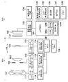
図1は、実施形態に係る撮像装置の一例としてデジタルカメラの機能構成例を示すブロック図である。上述したように、本実施形態のデジタルカメラはレンズ交換式一眼レフカメラであり、レンズユニット100とカメラ本体120とを有する。レンズユニット100は図中央の点線で示されるマウントMを介して、カメラ本体120に装着される。
<First Embodiment>
(Description of configuration of imaging apparatus-lens unit)
FIG. 1 is a block diagram illustrating a functional configuration example of a digital camera as an example of an imaging apparatus according to the embodiment. As described above, the digital camera of this embodiment is a lens interchangeable single-lens reflex camera, and includes the
レンズユニット100は、光学系(第1レンズ群101、絞り兼用シャッタ102、第2レンズ群103、フォーカスレンズ群(以下、単に「フォーカスレンズ」という)104)及び、駆動/制御系を有する。このようにレンズユニット100は、フォーカスレンズ104を含み、被写体の光学像を形成する撮影レンズである。
The
第1レンズ群101は、レンズユニット100の先端に配置され、光軸方向OAに移動可能に保持される。絞り兼用シャッタ102は、その開口径を調節することで撮影時の光量を調節する機能のほか、静止画撮影時には露出時間を制御するメカニカルシャッタとしても機能する。絞り兼用シャッタ102及び第2レンズ群103は一体で光軸方向OAに移動可能であり、第1レンズ群101と連動して移動することによりズーム機能を実現する。また、フォーカスレンズ104も光軸方向OAに移動可能であり、位置に応じてレンズユニット100が合焦する被写体距離(合焦距離)が変化する。フォーカスレンズ104の光軸方向OAにおける位置を制御することにより、レンズユニット100の合焦距離を調節する焦点調節を行う。
The
駆動/制御系は、ズームアクチュエータ111、絞りシャッタアクチュエータ112、フォーカスアクチュエータ113、ズーム駆動回路114、絞りシャッタ駆動回路115、フォーカス駆動回路116、レンズMPU(マイクロプロセッサ)117、レンズメモリ118を有する。
The drive / control system includes a
ズーム駆動回路114は、撮影者のズーム操作に応じてズームアクチュエータ111を駆動して、第1レンズ群101や第2レンズ群103を光軸方向OAに駆動することで、レンズユニット100の光学系の画角を制御する。絞りシャッタ駆動回路115は、絞りシャッタアクチュエータ112を用いて絞り兼用シャッタ102を駆動し、絞り兼用シャッタ102の開口径や開閉動作を制御する。フォーカス駆動回路116は、フォーカスアクチュエータ113を用いてフォーカスレンズ104を光軸方向OAに駆動し、レンズユニット100の光学系の合焦距離を変化させる。また、フォーカス駆動回路116は、フォーカスアクチュエータ113を用いてフォーカスレンズ104の現在位置を検出する。
The
レンズMPU(マイクロプロセッサ)117は、レンズユニット100に係る全ての演算、制御を行い、ズーム駆動回路114、絞りシャッタ駆動回路115、フォーカス駆動回路116を制御する。また、レンズMPU117は、マウントMを通じてカメラMPU125と接続され、コマンドやデータを通信する。例えば、レンズMPU117はフォーカスレンズ104の光軸上の位置を検出し、カメラMPU125からの要求に対してレンズ位置情報を通知する。このレンズ位置情報は、フォーカスレンズ104の光軸方向OAにおける位置、光学系が移動していない状態の射出瞳の光軸方向OAにおける位置および直径、射出瞳の光束を制限するレンズ枠の光軸方向OAにおける位置および直径などの情報を含む。またレンズMPU117は、カメラMPU125からの要求に応じて、ズーム駆動回路114、絞りシャッタ駆動回路115、フォーカス駆動回路116を制御する。レンズメモリ118には自動焦点検出に必要な光学情報が予め記憶されている。カメラMPU125は例えば内蔵する不揮発性メモリやレンズメモリ118に記憶されているプログラムを実行することで、レンズユニット100の動作を制御する。
The lens MPU (microprocessor) 117 performs all calculations and control related to the
(撮像装置の構成の説明−カメラ本体)
カメラ本体120は、光学系(光学ローパスフィルタ(LPF)121および撮像素子122)と、駆動/制御系とを有する。レンズユニット100の第1レンズ群101、絞り兼用シャッタ102、第2レンズ群103、フォーカスレンズ104と、カメラ本体120の光学LPF121は撮影光学系を構成する。
(Explanation of imaging device configuration-camera body)
The
光学LPF121は、撮影画像の偽色やモアレを軽減する。撮像素子122はCMOSイメージセンサと周辺回路で構成され、横方向m画素、縦方向n画素(n,mは2以上の整数)が配置される。本実施形態の撮像素子122は、図2を参照して後述するような構成の光電変換素子を有する画素を含み、撮影光学系を介して入射した光を光電変換して、画像信号を出力する。画像処理回路124は、撮像素子122が出力する画像信号から、位相差AF用のデータと、表示、記録、およびコントラストAF(TVAF)用の画像データを生成する。
The
駆動/制御系は、撮像素子駆動回路123、画像処理回路124、カメラMPU125、表示器126、操作スイッチ群127、メモリ128、撮像面位相差焦点検出部129、TVAF焦点検出部130を有する。
The drive / control system includes an image
撮像素子駆動回路123は、撮像素子122の動作を制御するとともに、取得した画像信号をA/D変換してカメラMPU125及び画像処理回路124に送信する。画像処理回路124は、撮像素子122から出力された画像データに対し、例えばγ変換、ホワイトバランス調整処理、色補間処理、圧縮符号化処理など、デジタルカメラで行われる一般的な画像処理を行う。また、画像処理回路124は位相差AF用の信号も生成する。
The image
カメラMPU(マイクロプロセッサ)125は、カメラ本体120に係る全ての演算、制御を行う。そして、撮像素子駆動回路123、画像処理回路124、表示器126、操作スイッチ群127、メモリ128、撮像面位相差焦点検出部129、TVAF焦点検出部130を制御する。また、カメラMPU125はマウントMの信号線を介してレンズMPU117と接続され、レンズMPU117とコマンドやデータを通信する。カメラMPU125はレンズMPU117に対し、レンズ位置の取得要求や、所定の駆動量での絞り兼用シャッタ102、フォーカスレンズ104、ズームの駆動要求や、レンズユニット100に固有の光学情報の取得要求などを要求する。なお、カメラMPU125には、カメラ動作を制御するプログラムを格納したROM(Read Only Memory)125a、変数を記憶するRAM(Random Access Memory)125b、諸パラメータを記憶するEEPROM(Electrically Erasable Programmable Read−Only Memory)125cが内蔵されている。
A camera MPU (microprocessor) 125 performs all calculations and controls related to the
表示器126はLCD(liquid crystal display)などから構成され、カメラの撮影モードに関する情報、撮影前のプレビュー画像と撮影後の確認用画像、焦点検出時の合焦状態表示画像などを表示する。操作スイッチ群127は、電源スイッチ、レリーズ(撮影トリガ)スイッチ、ズーム操作スイッチ、撮影モード選択スイッチ等で構成される。メモリ128は、フラッシュメモリなどの着脱可能なメモリで、撮影済み画像を記録する。
The
撮像面位相差焦点検出部129は、画像処理回路124により得られる焦点検出用データを用いて位相差検出方式の焦点検出処理(撮像面位相差AF)を行う。より具体的には、画像処理回路124が、撮影光学系の一対の瞳領域を通過する光束で形成される一対の像データを焦点検出用データとして生成し、撮像面位相差焦点検出部129はこの一対の像データのずれ量に基づいて焦点ずれ量を検出する。このように、本実施形態の撮像面位相差焦点検出部129は、専用のAFセンサを用いず、撮像素子122の出力に基づく位相差AF(撮像面位相差AF)を行う。撮像面位相差焦点検出部129の動作については後で詳細に説明する。
The imaging surface phase difference focus detection unit 129 performs focus detection processing (imaging surface phase difference AF) of the phase difference detection method using the focus detection data obtained by the
TVAF焦点検出部130は、画像処理回路124が生成するTVAF用評価値(画像データのコントラスト情報)に基づいてコントラスト方式の焦点検出処理(TVAF)を行う。コントラスト方式の焦点検出処理では、フォーカスレンズ104を移動しながら複数のフォーカスレンズ位置で焦点評価値を算出し、焦点評価値がピークとなるフォーカスレンズ位置を合焦位置として検出する。
The TVAF
このように、本実施形態のデジタルカメラは撮像面位相差AFとTVAFの両方を実行可能であり、状況に応じて選択的に使用したり、組み合わせて使用したりすることができる。 As described above, the digital camera according to the present embodiment can execute both of the imaging plane phase difference AF and TVAF, and can be selectively used according to the situation or can be used in combination.
(焦点検出動作の説明:位相差AF)
以下、撮像面位相差焦点検出部129およびTVAF焦点検出部130の動作についてさらに説明する。最初に、撮像面位相差焦点検出部129の動作について説明する。
(Description of focus detection operation: phase difference AF)
Hereinafter, operations of the imaging plane phase difference focus detection unit 129 and the TVAF
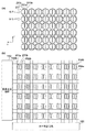
図2(a)は本実施形態における撮像素子122の画素配列を模式的に示した図で、2次元CMOSエリアセンサの縦(Y方向)6行と横(X方向)8列の範囲を、レンズユニット100側から観察した状態を示している。撮像素子122にはベイヤー配列のカラーフィルタが設けられ、奇数行の画素211には、左から順に緑(G)と赤(R)のカラーフィルタが交互に、偶数行の画素211には、左から順に青(B)と緑(G)のカラーフィルタが交互に配置されている。画素211において、円211iはオンチップマイクロレンズを表し、オンチップマイクロレンズの内側に配置された複数の矩形211a,211bはそれぞれ光電変換部である。
FIG. 2A is a diagram schematically showing the pixel arrangement of the
本実施形態の撮像素子122は、すべての画素の光電変換部がX方向に2分割され、個々の光電変換部の光電変換信号と、光電変換信号の和が独立して読み出し可能である。また、光電変換信号の和から一方の光電変換部の光電変換信号を減じることで、他方の光電変換部の光電変換信号に相当する信号を得ることができる。個々の光電変換部における光電変換信号は位相差AF用のデータとして用いたり、3D(3−Dimensional)画像を構成する視差画像の生成に用いたりすることもできる。また、光電変換信号の和は、通常の撮影画像データとして用いることができる。
In the
ここで、位相差AFを行う場合の画素信号について説明する。後述するように、本実施形態においては、図2(a)のマイクロレンズ211iと、分割された光電変換部211a,211bで撮影光学系の射出光束を瞳分割する。そして、同一画素行に配置された所定範囲内の複数の画素211について、光電変換部211aの出力をつなぎ合わせて編成したものをAF用A像、光電変換部211bの出力をつなぎ合わせて編成したものをAF用B像とする。光電変換部211a、211bの出力は、カラーフィルタの単位配列に含まれる緑、赤、青、緑の出力を加算して算出した疑似的な輝度(Y)信号を用いる。但し、赤、青、緑の色ごとに、AF用A像、B像を編成してもよい。このように生成したAF用A像とB像の相対的な像ずれ量を相関演算により検出することで、所定領域の焦点ずれ量(デフォーカス量)を検出することができる。本実施形態では、一方の光電変換部の出力と全光電変換部の出力の和を撮像素子122から読み出すものとする。例えば光電変換部211aの出力と、光電変換部211a,211bの出力の和とが読み出される場合、光電変換部211bの出力は和から光電変換部211aの出力を減じることで取得する。これにより、AF用A像とB像の両方を得ることができ、位相差AFが実現できる。このような撮像素子は、特開2004−134867号公報などに開示されるように公知であるため、これ以上の詳細に関する説明は省略する。
Here, a pixel signal when performing phase difference AF will be described. As will be described later, in the present embodiment, the exit lens of the photographing optical system is pupil-divided by the microlens 211i in FIG. 2A and the divided
図2(b)は本実施形態の撮像素子122の読み出し回路の構成例を示した図である。151は水平走査回路、153は垂直走査回路である。そして各画素の境界部には、水平走査ライン152a及び152bと、垂直走査ライン154a及び154bが配線され、各光電変換部はこれらの走査ラインを介して信号が外部に読み出される。
FIG. 2B is a diagram illustrating a configuration example of a readout circuit of the
なお、本実施形態の撮像素子122は上述の画素内の読み出し方法に加え、以下の2種類の読み出しモードを有する。第1の読み出しモードは全画素読み出しモードと称するもので、高精細静止画を撮像するためのモードである。この場合は、全画素の信号が読み出される。
Note that the
第2の読み出しモードは間引き読み出しモードと称するもので、動画記録、もしくはプレビュー画像の表示のみを行うためのモードである。この場合に必要な画素数は全画素よりも少ないため、画素群はX方向及びY方向ともに所定比率で間引いた画素のみ読み出す。また、高速に読み出す必要がある場合にも、同様に間引き読み出しモードを用いる。X方向に間引く際には、信号の加算を行いS/Nの改善を図り、Y方向に対する間引きは、間引かれる行の信号出力を無視する。位相差AFおよびコントラストAFも、通常、第2の読み出しモードで読み出された信号に基づいて行われる。 The second readout mode is called a thinning readout mode, and is a mode for performing only moving image recording or preview image display. In this case, since the number of pixels required is smaller than that of all the pixels, the pixel group reads only the pixels thinned out at a predetermined ratio in both the X direction and the Y direction. Similarly, when it is necessary to read out at high speed, the thinning-out reading mode is used similarly. When thinning out in the X direction, signals are added to improve the S / N ratio, and thinning out in the Y direction ignores the signal output of the thinned out rows. The phase difference AF and the contrast AF are also usually performed based on the signal read in the second reading mode.
図3は、本実施形態の撮像装置において、撮影光学系の射出瞳面と、像高ゼロすなわち像面中央近辺に配置された撮像素子の光電変換部の共役関係を説明する図である。撮像素子内の光電変換部と撮影光学系の射出瞳面は、オンチップマイクロレンズによって共役関係となるように設計される。そして撮影光学系の射出瞳は、一般的に光量調節用の虹彩絞りが置かれる面とほぼ一致する。一方、本実施形態の撮影光学系は変倍機能を有したズームレンズであるが、光学タイプによっては変倍操作を行うと、射出瞳の像面からの距離や大きさが変化する。図3(a)では、レンズユニット100の焦点距離が広角端と望遠端の中央にある状態を示している。この状態における射出瞳距離Zepを標準値として、オンチップマイクロレンズの形状や、像高(X,Y座標)に応じた偏心パラメータの最適設計がなされる。
FIG. 3 is a diagram for explaining the conjugate relationship between the exit pupil plane of the imaging optical system and the photoelectric conversion unit of the image sensor arranged near the center of the image plane, that is, in the vicinity of the center of the image plane, in the imaging apparatus of the present embodiment. The photoelectric conversion unit in the image sensor and the exit pupil plane of the photographing optical system are designed to have a conjugate relationship by an on-chip microlens. The exit pupil of the photographic optical system generally coincides with the surface on which the iris diaphragm for adjusting the amount of light is placed. On the other hand, the photographing optical system of the present embodiment is a zoom lens having a zooming function. However, depending on the optical type, when the zooming operation is performed, the distance and size of the exit pupil from the image plane change. FIG. 3A shows a state where the focal length of the
図3(a)において、101は第1レンズ群、101bは第1レンズ群を保持する鏡筒部材、104はフォーカスレンズ、104bはフォーカスレンズ104を保持する鏡筒部材である。102は絞り兼用シャッタで、102aは絞り開放時の開口径を規定する開口板、102bは絞り込み時の開口径を調節するための絞り羽根である。なお、撮影光学系を通過する光束の制限部材として作用する101b、102a、102b、及び104bは、像面から観察した場合の光学的な虚像を示している。また、絞り兼用シャッタ102の近傍における合成開口をレンズの射出瞳と定義し、前述したように像面からの距離をZepとしている。
In FIG. 3A, 101 is a first lens group, 101 b is a lens barrel member that holds the first lens group, 104 is a focus lens, and 104 b is a lens barrel member that holds the
画素211は像面中央近傍に配置されており、本実施形態では、中央画素と呼ぶ。中央画素211は、最下層より、光電変換部211a,211b、配線層211e〜211g、カラーフィルタ211h、及びオンチップマイクロレンズ211iの各部材で構成される。そして2つの光電変換部211a,211bはオンチップマイクロレンズ211iによって撮影光学系の射出瞳面に投影される。換言すれば、撮影光学系の射出瞳が、オンチップマイクロレンズ211iを介して、光電変換部の表面に投影される。
The
図3(b)は、撮影光学系の射出瞳面上における、光電変換部の投影像を示したもので、光電変換部211a及び211bに対する投影像は各々EP1a及びEP1bとなる。また本実施形態では、撮像素子122は、2つの光電変換部211aと211bのいずれか一方の出力と、両方の和の出力を得ることができる画素を有している。両方の和の出力は、撮影光学系のほぼ全瞳領域である投影像EP1a、EP1bの両方の領域を通過した光束を光電変換したものであるので、図3(b)でのTLと投影像EEP1a、EP1bが重複している面積に相当する光束に対応する値が出力される。
FIG. 3B shows a projected image of the photoelectric conversion unit on the exit pupil plane of the photographing optical system, and the projected images on the
図3(a)で、撮影光学系を通過する光束の最外部をLで示すと、光束Lは、絞りの開口板102aで規制されており、投影像EP1a及びEP1bは撮影光学系でケラレがほぼ発生していない。図3(b)では、図3(a)の光束Lを、TLで示している。TLで示す円の内部に、光電変換部の投影像EP1a、EP1bの大部分が含まれていることからも、ケラレがほぼ発生していないことがわかる。光束Lは、絞りの開口板102aでのみ制限されているため、TLは、102aと言い換えることができる。この際、像面中央では各投影像EP1aないしEP1bのケラレ状態は光軸に対して対称となり、各光電変換部211a及び211bが受光する光量は等しい。
In FIG. 3A, when the outermost part of the light beam passing through the photographing optical system is denoted by L, the light beam L is regulated by the
位相差AFを行う場合、カメラMPU125は撮像素子122から上述した2種類の出力を読み出すように撮像素子駆動回路123を制御する。そして、カメラMPU125は画像処理回路124に対して焦点検出領域の情報を与え、焦点検出領域内に含まれる画素の出力から、AF用A像およびB像のデータを生成して撮像面位相差焦点検出部129に供給するよう命令する。画像処理回路124はこの命令に従ってAF用A像およびB像のデータを生成して撮像面位相差焦点検出部129に出力する。画像処理回路124はまた、TVAF焦点検出部130に対してRAW画像データを供給する。
When performing phase difference AF, the
以上説明した様に、撮像素子122は位相差AFおよびコントラストAFの両方について、焦点検出装置の一部を構成している。
As described above, the
なお、ここでは一例として水平方向に射出瞳を2分割する構成を説明したが、撮像素子122の一部の画素については垂直方向に射出瞳を2分割する構成としてもよい。また、水平および垂直の両方向に射出瞳を分割する構成としてもよい。垂直方向に射出瞳を分割する画素を設けることにより、水平だけでなく垂直方向の被写体のコントラストに対応した位相差AFが可能となる。
Here, as an example, the configuration in which the exit pupil is divided into two in the horizontal direction has been described. However, for some pixels of the
(焦点検出動作の説明:コントラストAF)
次に、図4を用いて、コントラストAF(TVAF)について説明する。コントラストAFは、カメラMPU125とTVAF焦点検出部130が連携してフォーカスレンズ104の駆動と評価値の算出を繰り返し行うことで実現される。
(Description of focus detection operation: contrast AF)
Next, contrast AF (TVAF) will be described with reference to FIG. Contrast AF is realized by the
画像処理回路124からRAW画像データがTVAF焦点検出部130に入力されると、AF評価用信号処理回路401で、ベイヤー配列信号からの緑(G)信号の抽出と、低輝度成分を強調して高輝度成分を抑圧するガンマ補正処理が施される。本実施形態では、TVAFを緑(G)信号で行う場合を説明するが、赤(R)、青(B)、緑(G)の全ての信号を用いてもよい。また、RGB全色用いて輝度(Y)信号を生成してもよい。AF評価用信号処理回路401で生成される出力信号は、用いられた信号の種類によらず、以後の説明では、輝度信号Yと呼ぶ。
When RAW image data is input from the
なお、カメラMPU125から、領域設定回路413に焦点検出領域が設定されているものとする。領域設定回路413は、設定された領域内の信号を選択するゲート信号を生成する。ゲート信号は、ラインピーク検出回路402、水平積分回路403、ライン最小値検出回路404、ラインピーク検出回路409、垂直積分回路406、410、垂直ピーク検出回路405、407、411の各回路に入力される。また、各焦点評価値が焦点検出領域内の輝度信号Yで生成されるように、輝度信号Yが各回路に入力するタイミングが制御される。なお、領域設定回路413には、焦点検出領域に合わせて複数の領域が設定可能である。
It is assumed that a focus detection area is set in the
Yピーク評価値の算出方法について説明する。ガンマ補正された輝度信号Yはラインピーク検出回路402へ入力され、領域設定回路413に設定された焦点検出領域内で水平ラインごとのYラインピーク値が求められる。ラインピーク検出回路402の出力は垂直ピーク検出回路405において焦点検出領域内で垂直方向にピークホールドされ、Yピーク評価値が生成される。Yピーク評価値は、高輝度被写体や低照度被写体の判定に有効な指標である。
A method for calculating the Y peak evaluation value will be described. The gamma-corrected luminance signal Y is input to the line
Y積分評価値の算出方法について説明する。ガンマ補正された輝度信号Yは、水平積分回路403へ入力され、焦点検出領域内で水平ラインごとにYの積分値が求められる。更に、水平積分回路403の出力は垂直積分回路406において焦点検出領域内で垂直方向に積分されて、Y積分評価値が生成される。Y積分評価値は、焦点検出領域内全体の明るさを判断する指標として用いることができる。
A method for calculating the Y integral evaluation value will be described. The gamma-corrected luminance signal Y is input to the
Max−Min評価値の算出方法について説明する。ガンマ補正された輝度信号Yは、ラインピーク検出回路402に入力され、焦点検出領域内で水平ラインごとのYラインピーク値が求められる。また、ガンマ補正された輝度信号Yは、ライン最小値検出回路404に入力され、焦点検出領域内で水平ラインごとにYの最小値が検出される。検出された水平ラインごとのYのラインピーク値及び最小値は減算器に入力され、(ラインピーク値−最小値)が垂直ピーク検出回路407に入力される。垂直ピーク検出回路407は焦点検出領域内で垂直方向にピークホールドを行い、Max−Min評価値を生成する。Max−Min評価値は、低コントラスト・高コントラストの判定に有効な指標である。
A method for calculating the Max-Min evaluation value will be described. The gamma-corrected luminance signal Y is input to the line
領域ピーク評価値の算出方法について説明する。ガンマ補正された輝度信号Yは、BPF408に通すことによって特定の周波数成分が抽出され焦点信号が生成される。この焦点信号はラインピーク検出回路409へ入力され、焦点検出領域内で水平ラインごとのラインピーク値が求められる。ラインピーク値は、垂直ピーク検出回路411によって焦点検出領域内でピークホールドされ、領域ピーク評価値が生成される。領域ピーク評価値は、焦点検出領域内で被写体が移動しても変化が少ないので、合焦状態から再度合焦点を探す処理に移行するかどうかを判定する再起動判定に有効な指標である。
A method for calculating the region peak evaluation value will be described. A specific frequency component is extracted from the gamma-corrected luminance signal Y through the
全ライン積分評価値の算出方法について説明する。領域ピーク評価値と同様に、ラインピーク検出回路409は、焦点検出領域内で水平ラインごとのラインピーク値を求める。次に、ラインピーク値を垂直積分回路410に入力し、焦点検出領域内で垂直方向に全水平走査ライン数について積分して全ライン積分評価値を生成する。高周波全ライン積分評価値は、積分の効果でダイナミックレンジが広く、感度が高いので、主要なAF評価値である。従って、本実施形態では単に焦点評価値と記載した場合は全ライン積分評価値を意味する。
A method for calculating the total line integral evaluation value will be described. Similar to the area peak evaluation value, the line
カメラMPU125のAF制御部160は上述したそれぞれの焦点評価値を取得し、レンズMPU117を通じてフォーカスレンズ104を光軸方向に沿って所定方向に所定量移動させる。そして、新たに得られた画像データに基づいて上述した各種の評価値を算出し、全ライン積分評価値が最大値となるフォーカスレンズ位置を検出する。そして、現在のフォーカスレンズ位置と全ライン積分評価値が最大値となるフォーカスレンズ位置との差を、焦点ずれ量(デフォーカス量)として検出する。
The AF control unit 160 of the
本実施形態では、各種のAF用評価値を水平ライン方向および垂直ライン方向で算出する。これにより、水平、垂直の直交する2方向の被写体のコントラスト情報に対して焦点検出を行うことができる。 In the present embodiment, various AF evaluation values are calculated in the horizontal line direction and the vertical line direction. Thereby, focus detection can be performed on the contrast information of the subject in two directions that are orthogonal to each other in the horizontal and vertical directions.
(焦点検出領域の説明)
図5は、撮影範囲内における焦点検出領域の例を示す図である。上述の通り、位相差AFおよびコントラストAFのいずれも、焦点検出領域に含まれる画素から得られた信号に基づいて行われる。図5において、点線で示す長方形は撮像素子122の撮像範囲内の焦点検出領域219を示す。図5中の例では、afH(横)×afV(縦)[pix]の画素を含む。図5では、顔検出を行って焦点検出領域を設定した例を示したが、主被写体220を含むように焦点検出領域を設定しても良いし、ユーザーが事前に設定した焦点検出領域でも構わない。なお、図5は焦点検出領域の設定例であり、数、位置および大きさは図示したものに限定されない。
(Description of focus detection area)
FIG. 5 is a diagram illustrating an example of the focus detection area within the imaging range. As described above, both phase difference AF and contrast AF are performed based on signals obtained from pixels included in the focus detection area. In FIG. 5, a rectangle indicated by a dotted line indicates a
(焦点検出処理の流れの説明)
次に、図6を参照して、本実施形態のデジタルカメラにおける自動焦点検出(AF)動作について説明する。以下のAF処理動作は、他の主体が明記されている場合を除き、カメラMPU125が主体となって実行される。また、カメラMPU125がレンズMPU117にコマンド等を送信することによってレンズユニット100の駆動や制御を行う場合、説明を簡潔にするために動作主体をカメラMPU125として記載する場合がある。
(Explanation of focus detection process flow)
Next, an automatic focus detection (AF) operation in the digital camera of this embodiment will be described with reference to FIG. The following AF processing operations are executed mainly by the
図6(a)は、本実施形態におけるAF処理の流れを示すフローチャートである。まず、S1においてカメラMPU125は焦点検出領域を設定する。ここで設定される焦点検出領域219は、図5のように、主被写体220によって決められるものでも良いし、予め設定された焦点検出領域でも良い。ここでは、焦点検出領域に対して、焦点検出領域219を代表する座標(x1、y1)を設定する。この時の代表座標(x1、y1)は例えば、焦点検出領域219に対する重心位置であっても良い。
FIG. 6A is a flowchart showing the flow of AF processing in the present embodiment. First, in S1, the
S2では、焦点ずれ量(デフォーカス量)の検出を行う。本実施形態でカメラMPU125は、S1で設定された焦点検出領域において、位相差AFもしくはコントラストAFを適用してデフォーカス量DEFを求める。
In S2, a defocus amount (defocus amount) is detected. In the present embodiment, the
S3で、カメラMPU125は、ベストピント(BP)補正値の算出に必要なパラメータ(算出条件)を取得する。BP補正値は、フォーカスレンズ104の位置、ズーム状態を示す第1レンズ群101の位置、焦点検出領域の位置座標(x1、y1)など、撮影光学系の変化や焦点検出光学系の変化に伴い変化する。そのため、カメラMPU125は、例えばフォーカスレンズ104の位置、ズーム状態を示す第1レンズ群101の位置、および、焦点検出領域の位置座標(x1、y1)などの情報を取得する。
In S3, the
次に、S4では、収差情報を取得する。ここでの収差情報は、光学系の収差状態を表す情報であり、例えば、被写体の色、方向、空間周波数ごとの撮影光学系の結像位置に関する情報である。 Next, in S4, aberration information is acquired. The aberration information here is information representing the aberration state of the optical system, for example, information relating to the imaging position of the photographing optical system for each color, direction, and spatial frequency of the subject.
まず、図7(a)及び図7(b)を用いてレンズメモリ118に格納されている空間周波数ごとの収差情報の例について説明する。図7(a)は、撮影光学系のデフォーカスMTFを示すグラフである。横軸は、フォーカスレンズ104の位置を示しており、縦軸はMTFの強度を示している。図7(a)に描かれている4種の曲線は、空間周波数ごとのMTF曲線で、空間周波数F1(lp/mm)のMTF曲線がMTF1に対応し、同様に、空間周波数F2,F3,F4(lp/mm)がそれぞれMTF2,MTF3,MTF4に対応する。F1,F2,F3,F4の順に、空間周波数が高くなっている。また、LP4、LP5、LP5、LP6は、それぞれ、デフォーカスMTF1,MTF2,MTF3,MTF4の曲線の極大値に対応するフォーカスレンズ104の位置を示している。
First, an example of aberration information for each spatial frequency stored in the
図7(b)は、図7(a)に示したデフォーカスMTFの極大値を示すフォーカスレンズ104の位置を、上述した色(R、G、B)と方向(水平、垂直)との6通りの組み合わせの各々について示している。例えば、図7(b)において、曲線MTF_P_RHは、赤(R)、水平方向(H)のデフォーカスMTFの各空間周波数における極大値を示すフォーカスレンズ104の位置情報を表している。同様に、赤(R)以外の色(G、B)及び垂直方向(V)についても表している。この図7(b)に示す曲線は、例えば、赤(R)、水平方向(H)の組み合わせの場合、空間周波数fと撮像素子122上の焦点検出領域の位置座標(x,y)を変数とした以下の式(1)で表現される。なお、式(1)においてrh(n)(n=0〜8)は係数であり、本実施形態における収差情報である。
FIG. 7B shows the position of the
MTF_P_RH(f,x,y)=
(rh(0)×x+rh(1)×y+rh(2))×f2
+(rh(3)×x+rh(4)×y+rh(5))×f
+(rh(6)×x+rh(7)×y+rh(8)) …(1)
MTF_P_RH (f, x, y) =
(Rh (0) × x + rh (1) × y + rh (2)) × f 2
+ (Rh (3) × x + rh (4) × y + rh (5)) × f
+ (Rh (6) × x + rh (7) × y + rh (8)) (1)
なお、他の色及び方向の組み合わせについても、係数を変更することで、式(1)と同様の式で表される。また、本実施形態において、rh(n)(n=0〜8)は、レンズユニット100のレンズメモリ118に予め記憶され、カメラMPU125は、レンズMPU117に要求してrh(n)(n=0〜8)を取得するものとする。しかしながら、rh(n)(n=0〜8)はカメラRAM125bの不揮発性領域に記憶されていてもよい。
Note that other combinations of colors and directions are also expressed by the same expression as Expression (1) by changing the coefficients. In this embodiment, rh (n) (n = 0 to 8) is stored in advance in the
また、赤と垂直(MTF_P_RV)、緑と水平(MTF_P_GH)、緑と垂直(MTF_P_GV)、青と水平(MTF_P_BH)、青と垂直(MTF_P_BV)の各組み合わせにおける係数(rv,gh,gv,bh,bv)も、同様に記憶並びに取得できる。このように収差情報を関数化し、各項の係数を収差情報として記憶することで、レンズメモリ118やカメラRAM125bのデータ量を削減しつつ、撮影光学系の変化や焦点検出光学系の変化に対応した収差情報の記憶が可能になる。
In addition, coefficients (rv, gh, gv, bh, bv) can be stored and retrieved in the same manner. In this way, aberration information is converted into a function and the coefficient of each term is stored as aberration information, thereby reducing the amount of data in the
次に、S5では、撮像素子122から得られる信号のうち、撮影条件によるAF、撮像の重みづけ設定を行う。撮影条件とは、ユーザーが撮影画像を撮影する際の条件であり、例として、撮影画像の解像度、被写体、撮影光学系、画像処理の周波数特性などによるものである。詳細な動作は図6(b)を用いて後述するが、S5における動作の出力として、図8(a)のような焦点検出、撮影画像に関する第1、第2の重み付け情報の設定が行われる。ここでのAF、撮像の重みづけは、焦点状態を評価するコントラストの方向(水平、垂直)と色(R、G、B)、空間周波数の各組み合わせに対する、重み付けの大きさを示す情報である。
Next, in S <b> 5, among the signals obtained from the
次に、S6では、撮像素子122から得られる信号のうち、鑑賞条件によるパラメータの重みづけ計算を行う。鑑賞条件とは、ユーザーが撮影画像を鑑賞する際の条件であり、例として、撮影画像をモニタで見る際のモニタサイズ、モニタ解像度、モニタ表示率、鑑賞距離(ユーザーとモニタの距離)などによるものである。詳細な動作は図6(c)を用いて後述するが、図8(b)に示す撮影画像の周波数設定K_IMG_fq1〜K_IMG_fq4の重みづけ係数をS6で更新する。S6までで計算された、撮影画像を鑑賞する際の撮影光学系の収差状態に対応する重みづけ係数(K_IMG_H,K_IMG_V、K_IMG_R,K_IMG_G、K_IMG_B、K_IMG_fq1〜K_IMG_fq4)は、第1の重みづけ情報を形成する。また、焦点検出を行う際の撮影光学系の収差状態に対応する重みづけ係数(K_AF_H,K_AF_V、K_AF_R,K_AF_G、K_AF_B、K_AF_fq1〜K_AF_fq4)は第2の重みづけ情報を形成する。
Next, in S <b> 6, parameter weighting calculation based on viewing conditions is performed among signals obtained from the
次に、S7で、カメラMPU125は、S6までで設定された重みづけの係数と、S4で取得された収差情報から、BP補正値を算出する。
Next, in S7, the
具体的な動作を以下で説明する。まず、赤(R)、水平方向(H)の組み合わせについては、式(1)のx,yにS3で取得した焦点検出領域の位置情報(x、y)を代入する。この計算により式(1)は、以下の式(2)のような形式で表される。
MTF_P_RH(f)=Arh×f2+Brh×f+Crh …(2)
A specific operation will be described below. First, for the combination of red (R) and horizontal direction (H), the position information (x, y) of the focus detection area acquired in S3 is substituted for x and y in equation (1). By this calculation, the expression (1) is expressed in the form of the following expression (2).
MTF_P_RH (f) = Arh × f 2 + Brh × f + Crh (2)
カメラMPU125は、他の色、方向に関する収差情報MTF_P_RV(f)、MTF_P_GH(f)、MTF_P_GV(f)、MTF_P_BH(f)、MTF_P_BV(f)についても同様に計算する。
The
図7(b)は、S1で設定した焦点検出領域の位置情報を代入した後の収差情報の例を示し、横軸は空間周波数を、縦軸はデフォーカスMTFの極大値を示すフォーカスレンズ104の位置(ピーク位置)である。図示の通り、色収差が大きい場合には、色ごとの曲線が乖離し、縦横差が大きい場合には、図中の水平方向と垂直方向の曲線が乖離する。このように、本実施形態では、色(R、G、B)と評価方向(HとV)との組み合わせごとに、空間周波数に対応したデフォーカスMTF情報を有する。 FIG. 7B shows an example of aberration information after substituting the position information of the focus detection area set in S1, the horizontal axis indicates the spatial frequency, and the vertical axis indicates the maximum value of the defocus MTF. (Peak position). As shown in the figure, when the chromatic aberration is large, the curves for each color are deviated, and when the vertical and horizontal differences are large, the horizontal and vertical curves in the figure are deviated. As described above, in this embodiment, each combination of color (R, G, B) and evaluation direction (H and V) has defocus MTF information corresponding to the spatial frequency.
次に、カメラMPU125は、S6までで計算される焦点検出、撮影画像に関する方向、色、周波数の重みづけ係数(図8(a))で、収差情報を重み付けする。これにより、収差情報が、焦点検出、撮影画像で評価する色、方向に関して重み付けされ、撮影画像を鑑賞する際の収差状態と焦点検出を行う際の収差状態を得ることができる。具体的には、カメラMPU125は、焦点検出用の空間周波数特性MTF_P_AF(f)と撮影画像用の空間周波数特性MTF_P_IMG(f)を、式(3)および式(4)を用いて算出する。
MTF_P_AF(f)=
K_AF_R×K_AF_H×MTF_P_RH(f)
+K_AF_R×K_AF_V×MTF_P_RV(f)
+K_AF_G×K_AF_H×MTF_P_GH(f)
+K_AF_G×K_AF_V×MTF_P_GV(f)
+K_AF_B×K_AF_H×MTF_P_BH(f)
+K_AF_B×K_AF_V×MTF_P_BV(f) …(3)
MTF_P_IMG(f)=
K_IMG_R×K_IMG_H×MTF_P_RH(f)
+K_IMG_R×K_IMG_V×MTF_P_RV(f)
+K_IMG_G×K_IMG_H×MTF_P_GH(f)
+K_IMG_G×K_IMG_V×MTF_P_GV(f)
+K_IMG_B×K_IMG_H×MTF_P_BH(f)
+K_IMG_B×K_IMG_V×MTF_P_BV(f) …(4)
Next, the
MTF_P_AF (f) =
K_AF_R × K_AF_H × MTF_P_RH (f)
+ K_AF_R × K_AF_V × MTF_P_RV (f)
+ K_AF_G × K_AF_H × MTF_P_GH (f)
+ K_AF_G × K_AF_V × MTF_P_GV (f)
+ K_AF_B × K_AF_H × MTF_P_BH (f)
+ K_AF_B × K_AF_V × MTF_P_BV (f) (3)
MTF_P_IMG (f) =
K_IMG_R × K_IMG_H × MTF_P_RH (f)
+ K_IMG_R × K_IMG_V × MTF_P_RV (f)
+ K_IMG_G × K_IMG_H × MTF_P_GH (f)
+ K_IMG_G × K_IMG_V × MTF_P_GV (f)
+ K_IMG_B × K_IMG_H × MTF_P_BH (f)
+ K_IMG_B × K_IMG_V × MTF_P_BV (f) (4)
図7(c)に、離散的な空間周波数F1からF4について、式(3)に代入して得られるデフォーカスMTFがピーク(極大値)となるフォーカスレンズ位置(ピーク位置)LP4_AF、LP5_AF、LP6_AF、LP7_AFを示す。また、離散的な空間周波数F1からF4について、式(4)に代入して得られるデフォーカスMTFがピーク(極大値)となるフォーカスレンズ位置(ピーク位置)LP4_Img、LP5_Img、LP6_Img、LP7_Imgも示す。 FIG. 7C shows focus lens positions (peak positions) LP4_AF, LP5_AF, and LP6_AF at which the defocus MTF obtained by substituting into the expression (3) for the discrete spatial frequencies F1 to F4 is a peak (maximum value). , LP7_AF. Further, focus lens positions (peak positions) LP4_Img, LP5_Img, LP6_Img, and LP7_Img at which the defocus MTF obtained by substituting into the equation (4) for the discrete spatial frequencies F1 to F4 reaches a peak (maximum value) are also shown.
次に、カメラMPU125は、撮影画像の合焦位置(P_img)とAFによって検出される合焦位置(P_AF)を、以下の式(5)および(6)に従って算出する。算出には、上記式(3)及び(4)によって得られたデフォーカスMTF情報MTF_P(n)と、S6で得た評価帯域K_IMG_fq,K_AF_fqを用いる。
P_img=MTF_P_IMG(1)×K_IMG_fq(1)
+MTF_P_IMG(2)×K_IMG_fq(2)
+MTF_P_IMG(3)×K_IMG_fq(3)
+MTF_P_IMG(4)×K_IMG_fq(4) …(5)
P_AF=MTF_P_AF(1)×K_AF_FQ(1)
+MTF_P_AF(2)×K_AF_FQ(2)
+MTF_P_AF(3)×K_AF_FQ(3)
+MTF_P_AF(4)×K_AF_FQ(4) …(6)
Next, the
P_img = MTF_P_IMG (1) × K_IMG_fq (1)
+ MTF_P_IMG (2) × K_IMG_fq (2)
+ MTF_P_IMG (3) × K_IMG_fq (3)
+ MTF_P_IMG (4) × K_IMG_fq (4) (5)
P_AF = MTF_P_AF (1) × K_AF_FQ (1)
+ MTF_P_AF (2) × K_AF_FQ (2)
+ MTF_P_AF (3) × K_AF_FQ (3)
+ MTF_P_AF (4) × K_AF_FQ (4) (6)
つまり、カメラMPU125は、図7(c)で示した空間周波数ごとのデフォーカスMTFの極大値情報K_P_IMG(n),K_P_AF(n)を、撮影画像やAFの評価帯域K_IMG_fq,K_AF_fqで重みづけ加算する。これにより、撮影画像の合焦位置(P_img)とAFが検出する合焦位置(P_AF)を算出する。
That is, the
次にカメラMPU125は、BP補正値(BP)を、以下の式(7)により算出する。
BP=P_AF−P_img …(7)
Next, the
BP = P_AF−P_img (7)
次に、S8では、S2で得られたデフォーカス量DEFと、S7で得られたBP補正値BPとを用いて、式(8)によりフォーカスレンズ駆動量Mを求める。
M=DEF+BP …(8)
Next, in S8, the focus lens drive amount M is obtained by Expression (8) using the defocus amount DEF obtained in S2 and the BP correction value BP obtained in S7.
M = DEF + BP (8)
カメラMPU125は、フォーカスレンズ駆動量Mの分、光軸方向にフォーカスレンズを駆動させることで、ユーザーの意図にあった焦点画像を得る。
The
次に、図6(b)のフローチャートを参照しながら、撮影条件によるAF、撮影画像の重みづけ係数値の計算方法について、図9を用いて詳細に説明する。図9は、いずれも空間周波数毎の強度を示しており、横軸に空間周波数、縦軸に強度を示している。 Next, referring to the flowchart of FIG. 6B, an AF based on shooting conditions and a method of calculating a weighted coefficient value of a shot image will be described in detail with reference to FIG. FIG. 9 shows the intensity for each spatial frequency, with the horizontal axis indicating the spatial frequency and the vertical axis indicating the intensity.
S11では、まず、撮影画像の色、方向による焦点検出(AF)用の重みづけ係数を設定する。ここでは、図8(a)に示すように、焦点検出(AF)時の色の重みづけ係数K_AF_R,K_AF_G,K_AF_B、撮影画像の色の重みづけ係数K_IMG_R,K_IMG_G,K_IMG_Bを設定する。更に、焦点検出(AF)時の方向の重みづけ係数K_AF_H,K_AF_V、撮影画像の方向の重みづけ係数K_IMG_H,K_IMG_Vの係数値を設定する。以下、代表的な設定方法について説明する。例えば、方向の重みづけ係数K_AF_H、K_AF_V、K_IMG_H、K_IMG_Vに関しては、焦点検出方向が図2に示すような瞳分割形状で水平H方向のみの場合、
K_AF_H=1
K_AF_V=0
K_IMG_H=1
K_IMG_V=1
と設定すると良い。これは、焦点検出によるピント位置は水平方向Hによる収差に寄与するところが大きく、撮影画像のピント位置は水平方向Hと垂直方向Vを1:1で平均した収差状態の撮影画像でピント位置を判断することが一般的であるためである。
In S11, first, a weighting coefficient for focus detection (AF) based on the color and direction of the captured image is set. Here, as shown in FIG. 8A, color weighting coefficients K_AF_R, K_AF_G, K_AF_B at the time of focus detection (AF), and color weighting coefficients K_IMG_R, K_IMG_G, K_IMG_B of the captured image are set. Furthermore, coefficient values of the weighting coefficients K_AF_H and K_AF_V in the direction during focus detection (AF) and the weighting coefficients K_IMG_H and K_IMG_V in the direction of the captured image are set. Hereinafter, a typical setting method will be described. For example, for the direction weighting coefficients K_AF_H, K_AF_V, K_IMG_H, K_IMG_V, when the focus detection direction is the pupil division shape as shown in FIG.
K_AF_H = 1
K_AF_V = 0
K_IMG_H = 1
K_IMG_V = 1
It is good to set. This is because the focus position by focus detection largely contributes to the aberration in the horizontal direction H, and the focus position of the photographed image is determined by the photographed image in the aberration state in which the horizontal direction H and the vertical direction V are averaged by 1: 1. It is because it is common to do.
次に、色の重みづけ係数K_AF_R、K_AF_G、K_AF_B、K_IMG_R、K_IMG_G、K_IMG_Bに関しては、例えば、焦点検出用の画素がベイヤー配列中のGのみの場合、
K_AF_R=0
K_AF_G=1
K_AF_B=0
K_IMG_R=0.3
K_IMG_G=0.5
K_IMG_B=0.2
と設定しても良い。これは焦点検出時には、Gの色収差の影響のみピント位置に影響を与え、撮影画像は所望のホワイトバランス係数によって与えられた重みづけの各色の色収差による影響でピント位置が変動することに因る。代表的な設定方法について説明したが、方向、色に関しても、被写体の色や方向を検出して更新しても構わないし、ユーザーが任意に設定可能なもので合っても良い。また、色の分割数(R,G,B)を3、方向の分割数(H,V)を2としたが、より多くの分割数を設けても良い。分割数が多ければ多いほど、前述したBP補正値の算出時の重みづけ計算が複雑化し、カメラMPUの処理負荷は増えるが、より高精度なBP補正値の算出が可能になる。
Next, regarding the color weighting coefficients K_AF_R, K_AF_G, K_AF_B, K_IMG_R, K_IMG_G, and K_IMG_B, for example, when the pixel for focus detection is only G in the Bayer array,
K_AF_R = 0
K_AF_G = 1
K_AF_B = 0
K_IMG_R = 0.3
K_IMG_G = 0.5
K_IMG_B = 0.2
May be set. This is because at the time of focus detection, only the influence of the chromatic aberration of G affects the focus position, and the photographed image varies due to the influence of the chromatic aberration of each color of weighting given by the desired white balance coefficient. Although a typical setting method has been described, regarding the direction and color, the color and direction of the subject may be detected and updated, or may be arbitrarily set by the user. Further, although the color division number (R, G, B) is 3 and the direction division number (H, V) is 2, a larger number of divisions may be provided. The greater the number of divisions, the more complicated the weighting calculation at the time of calculating the BP correction value described above, and the processing load on the camera MPU increases, but it becomes possible to calculate the BP correction value with higher accuracy.
S12以降の処理は空間周波数に関する重みづけ係数K_AF_fq1〜K_AF_fq4、K_IMG_fq1〜K_IMG_fq4についての算出方法である。 The processing after S12 is a calculation method for weighting coefficients K_AF_fq1 to K_AF_fq4 and K_IMG_fq1 to K_IMG_fq4 related to the spatial frequency.
まず、S12において、撮影画像の記録解像度周波数特性を取得する。ここでは、撮影画像のナイキスト周波数を取得する。ナイキスト周波数を超えた撮影画像成分は写真に記録することができない。例えば、上述の通り、本実施形態の撮像素子122は2種類の読み出しモードを有する。第1の読み出しモード、すなわち全画素読み出しモードでは、信号生成時に空間周波数特性が変わる事はないため、図9におけるナイキスト周波数はNqである。例えば、画素ピッチ4μmの画素ピッチに対応するナイキスト周波数Nqは、
1/(0.004×2)=125[lp/mm]
である。
First, in S12, the recording resolution frequency characteristic of the captured image is acquired. Here, the Nyquist frequency of the captured image is acquired. A photographed image component exceeding the Nyquist frequency cannot be recorded in a photograph. For example, as described above, the
1 / (0.004 × 2) = 125 [lp / mm]
It is.
一方で、第2の読み出しモード、すなわち間引き読み出しモードの際には、信号生成時に空間周波数特性が変わる。例えば、第2の読み出しモードでX方向に1/3間引き処理が行われる場合を想定すると、第2の読み出しモードでの撮影画像は4μm×3=12μmの画素ピッチとなる。それに伴い、第2の読み出しモードでのナイキスト周波数Nqは、
1/(0.012×2)=42[lp/mm]
となり、解像できる撮影画像の周波数成分が低くなる。S12では、このように撮影画像として残る周波数限界[lp/mm]を撮影画像の画素ピッチから計算しておく。また、ナイキスト周波数を超えた周波数成分は、エイリアシング(偽解像)となる。撮影画像、AF用画像として、記録、解像できない周波数成分は、正しく鑑賞したり、焦点検出したりすることができないため、撮影画像のナイキスト周波数を基準に、S13以降の空間周波数情報の取得を行い、AF、撮像の周波数重み付けを計算する。下記の説明では、AF、撮像用の画像が同値のナイキスト周波数を持つ場合について説明する。しかしながら、撮像AF用の画像が第1の読み出しモード、AF用の画像が第2の読み出しモードで設定される場合など、AF、撮像で異なる画素ピッチである場合には、異なるナイキスト周波数を持つとして計算を行う。
On the other hand, in the second reading mode, that is, the thinning-out reading mode, the spatial frequency characteristics change when generating a signal. For example, assuming a case where 1/3 decimation processing is performed in the X direction in the second readout mode, a captured image in the second readout mode has a pixel pitch of 4 μm × 3 = 12 μm. Accordingly, the Nyquist frequency Nq in the second readout mode is
1 / (0.012 × 2) = 42 [lp / mm]
Thus, the frequency component of the captured image that can be resolved is lowered. In S12, the frequency limit [lp / mm] remaining as the captured image is calculated from the pixel pitch of the captured image. Further, the frequency component exceeding the Nyquist frequency becomes aliasing (false resolution). Since frequency components that cannot be recorded or resolved as a captured image or an AF image cannot be properly viewed or focus-detected, spatial frequency information acquisition from S13 onward is performed based on the Nyquist frequency of the captured image. And AF, imaging frequency weighting is calculated. In the following description, a case where AF and imaging images have the same Nyquist frequency will be described. However, if the image pickup AF image is set in the first readout mode and the AF image is set in the second readout mode, and the pixel pitch is different for AF and image pickup, it is assumed that the Nyquist frequency is different. Perform the calculation.
次に、S13では、被写体の空間周波数特性(I)を取得する。図9(a)は、被写体の空間周波数特性(I)の一例を示している。横軸上のfq1、fq2、fq3、fq4は、図8(b)で設定されている空間周波数であり、Nqは、撮像素子122の画素ピッチにより決まるナイキスト周波数を示す。空間周波数fq4は、fq1に比べ、ナイキスト周波数に近いので、高周波である。
Next, in S13, the subject's spatial frequency characteristic (I) is acquired. FIG. 9A shows an example of the spatial frequency characteristic (I) of the subject. Fq1, fq2, fq3, and fq4 on the horizontal axis are the spatial frequencies set in FIG. 8B, and Nq indicates the Nyquist frequency determined by the pixel pitch of the
空間周波数fq1、fq2、fq3、fq4、Nqについては、以後説明する図9(b)から図9(f)にも同様に示している。本実施形態では、被写体の空間周波数特性(I)は、焦点検出を行う被写体に応じて、用いる被写体の空間周波数特性を変更する。例えば、S1で設定された焦点検出領域において、撮影した画像信号に高速フーリエ変換(FFT)処理などの処理を行うことにより、図9(a)に示すような被写体の空間周波数情報を得ることができる。このような処理により、演算処理内容が増えるが、焦点検出を行う被写体に応じた補正値を算出できるため、高精度な焦点調節を行うことができる。また、より簡易的に、被写体のコントラスト情報の大小によって、予め記憶された数種の空間周波数特性を使い分けてもよい。なお、図9(a)では、被写体の空間周波数特性(I)は、曲線で描かれているが、離散的に空間周波数fq1、fq2、fq3、fq4に対応した値を有し、それをI(n)(1≦n≦4)と表す。 The spatial frequencies fq1, fq2, fq3, fq4, and Nq are similarly shown in FIGS. 9B to 9F described later. In the present embodiment, the spatial frequency characteristic (I) of the subject changes the spatial frequency characteristic of the subject to be used according to the subject for which focus detection is performed. For example, in the focus detection region set in S1, the subject spatial frequency information as shown in FIG. 9A can be obtained by performing processing such as fast Fourier transform (FFT) processing on the captured image signal. it can. Such processing increases the amount of calculation processing, but a correction value corresponding to the subject for which focus detection is performed can be calculated, so that highly accurate focus adjustment can be performed. Further, several types of spatial frequency characteristics stored in advance may be properly used depending on the magnitude of the contrast information of the subject. In FIG. 9A, the spatial frequency characteristic (I) of the subject is drawn with a curve, but has discrete values corresponding to the spatial frequencies fq1, fq2, fq3, and fq4. (N) (1 ≦ n ≦ 4).
次に、S14では、撮影光学系の周波数特性の取得を行う。図9(b)は、撮影光学系の空間周波数特性(O)の一例を示している。この光学情報は、レンズMPU117を通じて得てもよいし、カメラ内のRAM125bに記憶しておいてもよい。その際に記憶する情報は、デフォーカス状態毎の空間周波数特性でもよいし、合焦時の空間周波数特性のみでもよい。空間周波数BP補正値は、合焦近傍で算出するため、合焦時の空間周波数特性を用いれば、高精度に補正を行うことができる。但し、演算負荷は増えるものの、デフォーカス状態毎の空間周波数特性を用いると、より高精度に焦点調節を行うことができる。なお、図9(b)では、撮影光学系の空間周波数特性(O)は、曲線で描かれているが、離散的に空間周波数fq1、fq2、fq3、fq4に対応した値を有し、それをO(n)(1≦n≦4)と表す。
Next, in S14, the frequency characteristic of the photographing optical system is acquired. FIG. 9B shows an example of the spatial frequency characteristic (O) of the photographing optical system. This optical information may be obtained through the
次に、S15では、カメラ本体120の光学LPF121の周波数特性の取得を行う。図9(c)は、光学LPF121の空間周波数特性(L)の一例を示している。この情報は、カメラ内のRAM125bに記憶されている。なお、図9(c)では、光学LPF121の空間周波数特性(L)は、曲線で描かれているが、離散的に空間周波数fq1、fq2、fq3、fq4に対応した値を有し、それをL(n)(1≦n≦4)と表す。
Next, in S15, the frequency characteristic of the
ここでは、S13からS15において、被写体、撮影光学系、光学LP(光学LP:光学ローパス)の周波数特性をそれぞれ別々に取得している。そして、後述するS18において、各周波数fq(n)において掛け算を行うことで、特定の被写体を撮影光学系で撮影した時の空間周波数特性を取得する方法を示している。しかしながら、方法はこれに限らず、実際にカメラ本体120にレンズユニット100を装着して被写体を撮影して得られた撮像信号をフーリエ変換することで、I(n)×O(n)×L(n)の信号を得ることができる。このような方法で、撮影を行う度にI(n)×O(n)×L(n)の値を更新しても良い。
Here, in S13 to S15, the frequency characteristics of the subject, the photographing optical system, and the optical LP (optical LP: optical low pass) are acquired separately. In S18, which will be described later, a method of acquiring a spatial frequency characteristic when a specific subject is photographed by the photographing optical system by performing multiplication at each frequency fq (n) is shown. However, the method is not limited to this, and I (n) × O (n) × L is obtained by Fourier-transforming an imaging signal obtained by actually attaching the
次に、S16では、画像処理周波数特性の取得を行う。ここでは、撮影画像に施されるローパス(LP)処理や圧縮処理等による画像処理方法によって変更される周波数特性を計算する。 Next, in S16, image processing frequency characteristics are acquired. Here, a frequency characteristic that is changed by an image processing method such as low-pass (LP) processing or compression processing applied to a captured image is calculated.
図9(d)は、信号生成による空間周波数特性(M1,M2,M3)の一例を示している。M1は、撮影画像にLP処理や圧縮処理が全く施されなかった場合の周波数特性である。この場合、空間周波数特性が変わることは無いので、各周波数に対する係数は常に1を設定する。一方で、画像に施される処理として、エイリアシングの防止やS/Nの改善を図るため、信号の加算を行うことが考えられる。この場合、加算によるローパス効果が発生する。 FIG. 9D shows an example of spatial frequency characteristics (M1, M2, M3) by signal generation. M1 is a frequency characteristic when the LP process and the compression process are not performed at all on the captured image. In this case, since the spatial frequency characteristic does not change, the coefficient for each frequency is always set to 1. On the other hand, as processing performed on an image, it is conceivable to add signals in order to prevent aliasing and improve S / N. In this case, a low-pass effect due to addition occurs.
一例として、図10(a)を図9(d)のM1に対応する撮影画像、図10(b)をM2に対応する撮影画像とする。ここで、図10(c)に示すように、LP処理や圧縮処理が施されたM2に対応する撮影画像の1画素を、1+2+3、4+5+6、・・・のように、M1に対応する信号を加算したものとする。また、上述のような単純な加算処理だけでなく、画像圧縮時には、より高い周波数を残すような圧縮処理を行う場合もある。例えば、撮像素子駆動回路123内での加算処理は上述のような処理を行う場合でも、画像処理回路124内ではより高精細な撮影画像を残すため、高い周波数を残した画像圧縮を行う場合もある。この場合でも、画像処理のLP効果に合わせた周波数特性Mを設定すれば良い。例えば、画像処理回路124のLP効果をM3とし、撮像素子駆動回路123での加算効果をM2とすると、撮影画像がどちらの回路を通って現在の記録解像度になったかによって、選択する画像処理周波数特性をM2かM3に切り替えれば良い。
As an example, FIG. 10A is a captured image corresponding to M1 in FIG. 9D, and FIG. 10B is a captured image corresponding to M2. Here, as shown in FIG. 10C, a pixel corresponding to M2 that has been subjected to LP processing and compression processing is represented by a signal corresponding to M1, such as 1 + 2 + 3, 4 + 5 + 6,. It shall be added. In addition to the simple addition process as described above, a compression process that leaves a higher frequency may be performed during image compression. For example, the addition processing in the image
このように、S16では、S15における撮影画像の画素数、画素ピッチが同じ(ナイキスト周波数が同じ)であっても、画像処理方法によって、撮影画像に残る周波数帯域が異なる場合があるので、その重みづけを与える。なお、図9(d)では、信号生成による空間周波数特性(M1,M2,M3)は、曲線で描かれているが、離散的に空間周波数fq1、fq2、fq3、fq4に対応した値を有し、それをM1(n)、M2(n)、M3(n)(1≦n≦4)と表す。 Thus, in S16, even if the number of pixels and the pixel pitch of the captured image in S15 are the same (the Nyquist frequency is the same), the frequency band remaining in the captured image may differ depending on the image processing method. Give In FIG. 9D, the spatial frequency characteristics (M1, M2, M3) due to signal generation are drawn as curves, but discretely have values corresponding to the spatial frequencies fq1, fq2, fq3, and fq4. It is expressed as M1 (n), M2 (n), M3 (n) (1 ≦ n ≦ 4).
次に、S17では、AFデジタル処理の周波数特性と撮影画像を鑑賞する際の代表的な空間周波数特性を取得する。焦点検出は、デジタルフィルタをかけて行うのが一般的である。 Next, in S17, a frequency characteristic of AF digital processing and a typical spatial frequency characteristic when viewing a captured image are acquired. In general, focus detection is performed by applying a digital filter.
図9(e)は、撮影画像を鑑賞する際の空間周波数ごとの感度を示す空間周波数特性(D1)とAF評価信号の処理時に用いるデジタルフィルタの空間周波数特性(D2)を示している。撮影画像を鑑賞する際の空間周波数毎の感度は、画像を鑑賞する表示部であるモニタサイズやモニタ解像度、モニタ表示率、鑑賞距離などにより影響を受ける。鑑賞条件による変化量の算出方法は、図6(c)を用いて後述する。ここでは、例えば、代表的な値として、モニタサイズ=A3、モニタ解像度=1920×1080、モニタ表示率100%、鑑賞距離=500mmなどの条件下での鑑賞時の空間周波数毎の感度を設定し、記憶している。なお、図9(e)では、信号生成による空間周波数特性(D1、D2)は、曲線で描かれているが、離散的に空間周波数fq1、fq2、fq3、fq4に対応した値を有し、それをD1(n)、D2(n)(1≦n≦4)と表す。
FIG. 9E shows the spatial frequency characteristic (D1) indicating the sensitivity for each spatial frequency when viewing a captured image, and the spatial frequency characteristic (D2) of the digital filter used when processing the AF evaluation signal. The sensitivity for each spatial frequency when viewing a captured image is affected by the monitor size, monitor resolution, monitor display rate, viewing distance, and the like, which are display units for viewing the image. A method of calculating the change amount according to the viewing conditions will be described later with reference to FIG. Here, for example, as a representative value, the sensitivity for each spatial frequency during viewing under conditions such as monitor size = A3, monitor resolution = 1920 × 1080, monitor
次に、S18では、S17までで得られた空間周波数の特性値から、焦点検出用と撮影画像用の空間周波数重み付け係数をそれぞれ算出する。以下の式(9)及び式(10)で、撮影画像の重み付け係数K_IMG_fq´及びAFの重み付け係数K_AF_fqの算出を行う。
K_IMG_fq´(n)=I(n)×O(n)×L(n)×M1(n)×D1(n)
(1≦n≦4) …(9)
K_AF_fq(n)=I(n)×O(n)×L(n)×M2(n)×D2(n)
(1≦n≦4) …(10)
Next, in S18, a spatial frequency weighting coefficient for focus detection and a captured image are calculated from the spatial frequency characteristic values obtained up to S17. The weighted coefficient K_IMG_fq ′ of the captured image and the weighting coefficient K_AF_fq of the AF are calculated by the following expressions (9) and (10).
K_IMG_fq ′ (n) = I (n) × O (n) × L (n) × M1 (n) × D1 (n)
(1 ≦ n ≦ 4) (9)
K_AF_fq (n) = I (n) * O (n) * L (n) * M2 (n) * D2 (n)
(1 ≦ n ≦ 4) (10)
図9(f)に、撮影画像の重み付け係数K_IMG_fq´とAFの重み付け係数K_AF_fqを示す。式(9)及び式(10)のような計算を行うことにより、撮影画像の合焦状態を決定する因子に対して、空間周波数毎に、どの程度の影響度合いを有するかを定量化することができる。同様に、焦点検出結果が有する誤差が、空間周波数毎に、どの程度の影響度合いを有するかを定量化することができる。また、検出された被写体ごとに図9(a)の空間周波数特性(I)を更新することで、被写体の空間周波数特性に対応した重み付け係数K_IMG_fqとK_AF_fq´を得ることができる。 FIG. 9F shows the weighting coefficient K_IMG_fq ′ of the captured image and the AF weighting coefficient K_AF_fq. Quantifying the degree of influence of each spatial frequency on the factor that determines the in-focus state of the captured image by performing calculations such as Expression (9) and Expression (10) Can do. Similarly, it is possible to quantify how much influence the error of the focus detection result has for each spatial frequency. Further, by updating the spatial frequency characteristic (I) of FIG. 9A for each detected subject, the weighting coefficients K_IMG_fq and K_AF_fq ′ corresponding to the spatial frequency characteristic of the subject can be obtained.
また、前述したように、S16で行われる画像処理の空間周波数特性がM2から、M3となる場合には、式(10)におけるM2(n)をM3(n)に置き換えて重み付け係数を算出すれば良い。 As described above, when the spatial frequency characteristic of the image processing performed in S16 changes from M2 to M3, the weighting coefficient can be calculated by replacing M2 (n) in Equation (10) with M3 (n). It ’s fine.
また、全ての計算を焦点検出動作内で行う必要はないため、例えば、撮影光学系と被写体の空間周波数特性のみは予め計算し、カメラ内に記憶しておくことにより、データの記憶容量の低減や演算量の低減をはかってもよい。 In addition, since it is not necessary to perform all calculations within the focus detection operation, for example, only the spatial frequency characteristics of the photographing optical system and the subject are calculated in advance and stored in the camera, thereby reducing the data storage capacity. Alternatively, the amount of calculation may be reduced.
図9では、4つの空間周波数(fq1〜fq4)を用いて説明したが、データを有する空間周波数の数が多いほど、撮影画像やAFの評価帯域の空間周波数特性を分解能良く再現することができ、精度のよい補正値の算出を行うことができる。逆に、重みづけを行う空間周波数を少なくすることにより、演算量の低減を行うことができる。また、撮影画像の評価帯域とAF評価帯域の空間周波数特性を代表する空間周波数を各々1つずつ持ち、演算を行ってもよい。 In FIG. 9, the four spatial frequencies (fq1 to fq4) have been described. However, as the number of spatial frequencies having data increases, the spatial frequency characteristics of the captured image and the AF evaluation band can be reproduced with high resolution. Therefore, it is possible to calculate a correction value with high accuracy. Conversely, the amount of calculation can be reduced by reducing the spatial frequency for weighting. Further, the calculation may be performed with one spatial frequency representing the spatial frequency characteristics of the evaluation band of the captured image and the AF evaluation band.
次に、図6(c)のフローチャートを参照しながら、撮影条件による撮影画像の空間周波数重みづけ値の計算方法について、図11、図12を用いて詳細に説明する。 Next, with reference to the flowchart of FIG. 6C, a method for calculating the spatial frequency weighting value of the captured image according to the imaging conditions will be described in detail with reference to FIGS.
前述したように、図6(b)では、表示部の特定鑑賞条件(例として、モニタサイズ=A3、モニタ解像度=1920×1080、モニタ表示率100%、鑑賞距離=500mm)下での撮像の空間周波数重み付けを算出したものであった。図6(c)では、ユーザーの鑑賞条件(モニタサイズ、モニタ解像度、モニタ表示率、鑑賞距離など)によって変化する着目周波数を変更可能にする。鑑賞条件(モニタサイズ、モニタ解像度、モニタ表示率、鑑賞距離など)に関連するパラメータは、鑑賞者が入力、選択可能なものであっても良いし、後述する方法で検出を行っても良い。
As described above, in FIG. 6B, imaging under specific viewing conditions of the display unit (for example, monitor size = A3, monitor resolution = 1920 × 1080, monitor
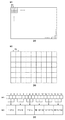
前提として、デジタルカメラでの撮影画像が図11(a)にあるように、5×5[pix]で形成されていたとする。このときの図6(b)で示した特定の鑑賞条件での画像イメージを図11(b)に示す。図11(b)はデジタルカメラでの撮影画像をモニタ表示する際の一例を示しており、ここでの表示部のモニタサイズ:Z1、モニタ解像度:R1、表示率:B1、鑑賞距離:E1での例を示している。表示部のモニタサイズとは、モニタ表示部のサイズ(M_H[mm]×M_V[mm])を示す。現在では、モニタサイズは、17インチのものから4K対応による大画面のものまで様々なサイズがあるが、ここでは表示部のサイズに変更が生じた際のユーザーの鑑賞周波数変化に対応する。 As a premise, it is assumed that an image captured by a digital camera is formed with 5 × 5 [pix] as shown in FIG. FIG. 11B shows an image image under the specific viewing condition shown in FIG. 6B at this time. FIG. 11B shows an example when the captured image of the digital camera is displayed on the monitor. The monitor size of the display unit is Z1, monitor resolution is R1, display rate is B1, and viewing distance is E1. An example is shown. The monitor size of the display unit indicates the size of the monitor display unit (M_H [mm] × M_V [mm]). At present, there are various monitor sizes ranging from 17 inches to large screens that support 4K, but here, it corresponds to changes in the viewing frequency of the user when the size of the display unit changes.
次に、表示部のモニタ解像度とは、モニタ上の総画素数(P_H[pix]×P_V[pix])を示す。同一のモニタサイズで比較する場合、画素数が多いほど高精細な表示が可能となる。上述のモニタサイズM_H[mm]×M_V[mm]と、モニタの1画素の大きさMP[mm]が既知であれば、
P_H[pix]= M_H[mm]/ MP[mm]
P_V[pix]= M_V[mm]/ MP[mm]
と求めることもできる。
Next, the monitor resolution of the display unit indicates the total number of pixels on the monitor (P_H [pix] × P_V [pix]). When comparing with the same monitor size, a higher-definition display becomes possible as the number of pixels increases. If the monitor size M_H [mm] × M_V [mm] and the size MP [mm] of one pixel of the monitor are known,
P_H [pix] = M_H [mm] / MP [mm]
P_V [pix] = M_V [mm] / MP [mm]
You can also ask.
次に、表示部のモニタ表示率とは、モニタ上の拡大表示率のことであり、一般的に、表示率=100%と指定した場合には、図11(a)上に示す記録画素の1[pix]×1[pix]の情報=モニタ上の1[pix]×1[pix]の情報として表示する。表示率=200%の場合には、記録画素の1[pix]×1[pix]の情報=モニタ上の2[pix]×2[pix]の情報として表示する。 Next, the monitor display rate of the display unit is an enlarged display rate on the monitor. Generally, when the display rate is designated as 100%, the recording pixel shown in FIG. 1 [pix] × 1 [pix] information = displayed as 1 [pix] × 1 [pix] information on the monitor. When the display rate is 200%, information of 1 [pix] × 1 [pix] of the recording pixel is displayed as information of 2 [pix] × 2 [pix] on the monitor.
次に、鑑賞距離とは、図11(c)に示すように、例えば、ユーザーとモニタとのZ軸方向の距離である。ユーザーの視点位置から出る点線はユーザーの画角であり、角度θで表される。 Next, the viewing distance is, for example, the distance between the user and the monitor in the Z-axis direction, as shown in FIG. The dotted line coming out from the user's viewpoint position is the angle of view of the user and is represented by an angle θ.
S21では、まず、鑑賞情報1として、表示部のモニタサイズの情報取得を行う。図11(d)は、モニタサイズZ=Z2となり、サイズが小さくなった場合の例を図示している。なお、このとき、その他の鑑賞条件(被写体、モニタ解像度、モニタ表示率、鑑賞距離)は変更がないものとして説明する。
In S21, first, as the
この場合、モニタ解像度:R1(総画素数)が同じで、モニタサイズが小さくなっているため、モニタの1画素の大きさMP[mm]は、図11(b)に示す場合に比べて小さくなる(MPc[mm])。さらに、モニタ表示率も同じであるので、相対的に、図11(b)に比べて、モニタ上に表示される被写体の大きさは小さくなる。つまり、モニタが小さくなると、同じ距離でモニタを観察しているユーザーにとっては、被写体の中の高周波な成分は見えにくくなる。具体的な例を述べると、図11(d)で顔が映し出されている場合、睫などの高周波な成分よりも輪郭などの低域な部分でユーザーはピントを評価する。この重み付け情報を表した例が図12(a)のG1である。図9と同様に、fq1、fq2、fq3、fq4は、図8(b)で設定されている空間周波数であり、Nqは、撮像素子122の画素ピッチにより決まるナイキスト周波数を示す。
In this case, since the monitor resolution: R1 (total number of pixels) is the same and the monitor size is small, the size MP [mm] of one pixel of the monitor is smaller than that shown in FIG. (MPc [mm]). Furthermore, since the monitor display rate is the same, the size of the subject displayed on the monitor is relatively smaller than that in FIG. That is, as the monitor becomes smaller, it becomes difficult for a user who observes the monitor at the same distance to see high-frequency components in the subject. To describe a specific example, when a face is projected in FIG. 11D, the user evaluates the focus at a lower frequency part such as a contour than a high-frequency component such as wrinkles. An example representing this weighting information is G1 in FIG. Similarly to FIG. 9,
図12(a)の二点差線は、モニタサイズ:Z1のときの空間周波数の重み付け特性例を表している。それに対し、現在のモニタサイズはZ2であるので、モニタの大きさは、Z2/Z1である。このとき、鑑賞時の空間周波数の重み付けは、モニタの大きさに比例するモニタの画素ピッチMP、MPcを利用し、一例として、鑑賞周波数をMPc/MP低域に重みを強くしたG1のように表現する。なお、図12(a)では、鑑賞条件1(モニタサイズ)の空間周波数特性(G1)は、曲線で描かれているが、離散的に空間周波数fq1、fq2、fq3、fq4に対応した値を有し、それをG1(n)(1≦n≦4)と表す。 The two-dot chain line in FIG. 12A represents an example of the spatial frequency weighting characteristic when the monitor size is Z1. On the other hand, since the current monitor size is Z2, the monitor size is Z2 / Z1. At this time, weighting of the spatial frequency at the time of viewing uses the pixel pitches MP and MPc of the monitor proportional to the size of the monitor, and as an example, the weight of the viewing frequency is MPc / MP low range and the weight is increased like G1. Express. In FIG. 12A, the spatial frequency characteristic (G1) of the viewing condition 1 (monitor size) is drawn as a curve, but values corresponding to the spatial frequencies fq1, fq2, fq3, and fq4 are discretely obtained. It is expressed as G1 (n) (1 ≦ n ≦ 4).
次に、S22では、鑑賞情報2として、モニタ解像度の情報取得を行う。図11(e)にモニタ解像度R=R2となり、解像度が低くなった場合の例を図示している。なお、このとき、その他の鑑賞条件(被写体、モニタサイズ、モニタ表示率、鑑賞距離)は変更がないものとして説明する。
Next, in S22, monitor resolution information is acquired as viewing
この場合、モニタサイズ:Z1が同じで、モニタ解像度が低くなっているため、モニタの1画素の大きさMP[mm]は、図11(b)に示す場合に比べて大きくなる(MPd[mm])。さらに、モニタ表示率も同じであるので、相対的に、図11(b)に比べて、モニタ上に表示される被写体の大きさは大きくなる。つまり、被写体が大きくなると、同じ距離でモニタを観察しているユーザーにとっては、被写体の中の高周波な成分が見えやすくなる。具体的な例を述べると、図11(e)で顔が映し出されている場合、睫などの高周波な成分でユーザーはピント評価を行う。この重み付け情報を表した例が図12(b)のG2である。図9と同様に、fq1、fq2、fq3、fq4は、図8(b)で設定されている空間周波数であり、Nqは、撮像素子の画素ピッチにより決まるナイキスト周波数を示す。 In this case, since the monitor size: Z1 is the same and the monitor resolution is low, the size MP [mm] of one pixel of the monitor is larger than that shown in FIG. 11B (MPd [mm] ]). Furthermore, since the monitor display rate is the same, the size of the subject displayed on the monitor is relatively larger than that in FIG. That is, when the subject becomes large, a user who observes the monitor at the same distance can easily see a high-frequency component in the subject. To describe a specific example, when a face is projected in FIG. 11E, the user performs focus evaluation with a high-frequency component such as wrinkles. An example representing this weighting information is G2 in FIG. Similarly to FIG. 9, fq1, fq2, fq3, and fq4 are the spatial frequencies set in FIG. 8B, and Nq represents the Nyquist frequency determined by the pixel pitch of the image sensor.
図12(b)の二点差線は、モニタ解像度:R1のときの空間周波数の重み付け特性例を表している。それに対し、現在のモニタ解像度はR2であるので、モニタの解像度比は、R2/R1である。このとき、鑑賞時の空間周波数の重み付けは、モニタの解像度に比例するモニタの画素ピッチMP、MPdを利用し、一例として、鑑賞周波数をMPd/MP高周波側に重みを強くしたG2のように表現する。なお、図12(b)では、鑑賞条件2(モニタ解像度)の空間周波数特性(G2)は、曲線で描かれているが、離散的に空間周波数fq1、fq2、fq3、fq4に対応した値を有し、それをG2(n)(1≦n≦4)と表す。 A two-dot difference line in FIG. 12B represents an example of a spatial frequency weighting characteristic when the monitor resolution is R1. On the other hand, since the current monitor resolution is R2, the monitor resolution ratio is R2 / R1. At this time, weighting of the spatial frequency at the time of viewing is expressed as G2 using the monitor pixel pitches MP and MPd proportional to the resolution of the monitor, and as an example, the viewing frequency is increased to the MPd / MP high frequency side. To do. In FIG. 12B, the spatial frequency characteristic (G2) of the viewing condition 2 (monitor resolution) is drawn with a curve, but values corresponding to the spatial frequencies fq1, fq2, fq3, and fq4 are discretely obtained. It is expressed as G2 (n) (1 ≦ n ≦ 4).
次に、S23では、鑑賞情報3として、モニタ表示率の情報取得を行う。図11(f)にモニタ表示率B=B2となり、表示率が高くなった場合の例を図示している。なお、このとき、その他の鑑賞条件(被写体、モニタサイズ、モニタ解像度、鑑賞距離)は変更がないものとして説明する。
Next, in S23, the monitor display rate information is acquired as the
この場合、モニタサイズ、モニタ解像度が同じであるため、モニタの1画素の大きさMP[mm]は図11(b)と同じである。しかし、モニタ表示率が異なるので、相対的に、図11(b)に比べて、モニタ上に表示される被写体の大きさは大きくなる。つまり、表示率が大きくなると、同じ距離でモニタを観察しているユーザーにとっては、被写体の中の高周波な成分が見えやすくなる。具体的な例を述べると、図11(f)中で顔が映し出されている場合、睫などの高周波な成分でユーザーはピント評価を行う。この重み付け情報を表した例が図12(c)のG3である。図9と同様に、fq1、fq2、fq3、fq4は、図8(b)で設定されている空間周波数であり、Nqは、撮像素子の画素ピッチにより決まるナイキスト周波数を示す。 In this case, since the monitor size and the monitor resolution are the same, the size MP [mm] of one pixel of the monitor is the same as that in FIG. However, since the monitor display rate is different, the size of the subject displayed on the monitor is relatively larger than that in FIG. In other words, when the display rate increases, a user who observes the monitor at the same distance can easily see a high-frequency component in the subject. To describe a specific example, when a face is projected in FIG. 11F, the user performs a focus evaluation with a high-frequency component such as wrinkles. An example of this weighting information is G3 in FIG. Similarly to FIG. 9, fq1, fq2, fq3, and fq4 are the spatial frequencies set in FIG. 8B, and Nq represents the Nyquist frequency determined by the pixel pitch of the image sensor.
図12(c)の二点差線は、モニタ表示率:B1のときの空間周波数の重み付け特性例を表している。それに対し、現在のモニタ表示率はB2であるので、モニタの表示率比は、B2/B1である。このとき、鑑賞時の空間周波数の重み付けは、一例として、鑑賞周波数をB2/B1高周波側に重みを強くしたG3のように表現する。なお、図12(c)では、鑑賞条件3(モニタ表示率)の空間周波数特性(G3)は、曲線で描かれているが、離散的に空間周波数fq1、fq2、fq3、fq4に対応した値を有し、それをG3(n)(1≦n≦4)と表す。 A two-dot difference line in FIG. 12C represents a weighting characteristic example of the spatial frequency when the monitor display rate is B1. On the other hand, since the current monitor display rate is B2, the monitor display rate ratio is B2 / B1. At this time, the weighting of the spatial frequency at the time of viewing is expressed as G3, for example, where the viewing frequency is increased to the B2 / B1 high frequency side. In FIG. 12C, the spatial frequency characteristic (G3) of the viewing condition 3 (monitor display rate) is drawn as a curve, but discretely corresponds to the spatial frequencies fq1, fq2, fq3, and fq4. It is expressed as G3 (n) (1 ≦ n ≦ 4).
また、モニタの表示率は、注視される被写体の大きさから決定しても良い。今、図11(a)のように取得された被写体はafH[pix]×afV[pix]で構成されているとする。この画像をモニタ上のOUT_H[pix],OUT_V[pix]で表示することを考える。S23におけるユーザーの入力が表示画素数OUT_H[pix],OUT_V[pix]であった場合、例えば、表示率B2は
B2=(OUT_H[pix]×OUT_V[pix])
/(afH[pix]×afV[pix])
として計算可能である。また、入力が表示画素数OUT_H[pix],OUT_V[pix]でなく、大きさOUTm_H[mm],OUTm_V[mm]の場合には、
The display rate of the monitor may be determined from the size of the subject being watched. Now, it is assumed that the subject acquired as shown in FIG. 11A is composed of afH [pix] × afV [pix]. Consider displaying this image with OUT_H [pix], OUT_V [pix] on the monitor. When the user input in S23 is the number of display pixels OUT_H [pix], OUT_V [pix], for example, the display rate B2 is B2 = (OUT_H [pix] × OUT_V [pix])
/ (AfH [pix] × afV [pix])
Can be calculated as Further, when the input is not the number of display pixels OUT_H [pix] and OUT_V [pix] but the sizes OUTm_H [mm] and OUTm_V [mm],
B2=
(OUTm_H[mm]/MP[mm]×OUTm_V[mm]/MP[mm])
/(afH[pix]×afV[pix])
として、モニタ上1pixの大きさMP[mm]を使って換算を行えばよいし、ユーザーがモニタ上で表示エリアを指定するようにしても良い。
B2 =
(OUTm_H [mm] / MP [mm] × OUTm_V [mm] / MP [mm])
/ (AfH [pix] × afV [pix])
Then, the conversion may be performed using the size MP [mm] of 1 pix on the monitor, or the user may designate the display area on the monitor.
次に、S24では、鑑賞情報4として、鑑賞距離の情報取得を行う。図11(g)に鑑賞距離E=E2となり、鑑賞距離が近くなった場合の例を図示している。なお、このとき、その他の鑑賞条件(被写体、モニタサイズ、モニタ解像度、モニタ表示率)は変更がないものとして説明する。
Next, in S24, the viewing distance information is acquired as the
この場合、モニタサイズ、モニタ解像度が同じであるため、モニタの1画素の大きさMP[mm]は図11(b)と同じである。また、モニタ表示率も同じであるので、モニタ上に表示される被写体の大きさも同じである。しかし、ユーザーの観察距離が近くなるとモニタ上の注視領域が狭くなる。図11(h)は、観察距離E2でのユーザーとモニタとのZ軸方向の距離を示した図である。画角θが同じであるとき、ユーザーは点線の範囲内しか視認できないので、図11(g)上のモニタでは、点線内のエリアに注視して表示画像の確認を行うことになる。つまり、距離が近くなると、同じモニタを観察しているユーザーにとっては、被写体の中の高周波な成分が見えやすくなる。具体的な例を述べると、図11(g)中で顔が映し出されている場合、睫などの高周波な成分でユーザーはピント評価を行う。この重み付け情報を表した例が図12(d)のG4である。図9と同様に、fq1、fq2、fq3、fq4は、図8(b)で設定されている空間周波数であり、Nqは、撮像素子の画素ピッチにより決まるナイキスト周波数を示す。 In this case, since the monitor size and the monitor resolution are the same, the size MP [mm] of one pixel of the monitor is the same as that in FIG. Also, since the monitor display rate is the same, the size of the subject displayed on the monitor is also the same. However, when the user's observation distance is short, the gaze area on the monitor is narrowed. FIG. 11H is a diagram showing the distance in the Z-axis direction between the user and the monitor at the observation distance E2. When the angle of view θ is the same, the user can visually recognize only within the range of the dotted line. Therefore, the monitor on FIG. 11G checks the display image by paying attention to the area within the dotted line. That is, when the distance is short, a user who is observing the same monitor can easily see a high-frequency component in the subject. To describe a specific example, when a face is projected in FIG. 11G, the user performs a focus evaluation with high frequency components such as wrinkles. An example of this weighting information is G4 in FIG. Similarly to FIG. 9, fq1, fq2, fq3, and fq4 are the spatial frequencies set in FIG. 8B, and Nq represents the Nyquist frequency determined by the pixel pitch of the image sensor.
図12(d)の二点差線は、鑑賞距離:E1のときの空間周波数の重み付け特性例を表している。それに対し、現在の鑑賞距離はE2であるので、注視エリアの大きさに対する鑑賞距離比は、E2tanθ/E1tanθ=E2/E1である。ここではモニタ画面縦方向の比に関して述べたが、横方向に関しても同様である。このとき、鑑賞時の空間周波数の重み付けは、一例として、鑑賞周波数をE2/E1高周波側に重みを強くしたG4のように表現する。なお、図12(d)では、鑑賞条件4(鑑賞距離)の空間周波数特性(G4)は、曲線で描かれているが、離散的に空間周波数fq1、fq2、fq3、fq4に対応した値を有し、それをG4(n)(1≦n≦4)と表す。 The two-dot difference line in FIG. 12D represents an example of the spatial frequency weighting characteristic when the viewing distance is E1. On the other hand, since the current viewing distance is E2, the ratio of the viewing distance to the size of the gaze area is E2 tan θ / E1 tan θ = E2 / E1. Although the ratio in the vertical direction of the monitor screen has been described here, the same applies to the horizontal direction. At this time, the weighting of the spatial frequency at the time of viewing is expressed as G4, for example, where the viewing frequency is increased to the E2 / E1 high frequency side. In FIG. 12D, the spatial frequency characteristic (G4) of the viewing condition 4 (viewing distance) is depicted by a curve, but values corresponding to the spatial frequencies fq1, fq2, fq3, and fq4 are discretely obtained. It is expressed as G4 (n) (1 ≦ n ≦ 4).
最後に、S25では、S24までで得られた空間周波数の特性値から、撮像の空間周波数重み付け係数を算出する。以下の式(13)で、撮影画像の評価帯域K_IMG_fqの算出を行う。
K_IMG_fq(n)=
K_IMG_fq´(n)×G1(n)×G2(n)×G3(n)×G4(n)
(1≦n≦4) …(13)
Finally, in S25, an imaging spatial frequency weighting coefficient is calculated from the spatial frequency characteristic values obtained up to S24. The evaluation band K_IMG_fq of the captured image is calculated by the following equation (13).
K_IMG_fq (n) =
K_IMG_fq ′ (n) × G1 (n) × G2 (n) × G3 (n) × G4 (n)
(1 ≦ n ≦ 4) (13)
図12(e)に、式(13)で算出されたモニタサイズ:Z2、モニタ解像度:R2、表示率:B2、鑑賞距離:E2での撮影画像の評価帯域K_IMG_fqの一例を示す。このような計算を行うことにより、鑑賞条件に因る撮影画像の合焦状態を決定する因子に対して、空間周波数毎に、どの程度の影響度合いを有するかを定量化することができる。 FIG. 12E shows an example of the evaluation band K_IMG_fq of the photographed image at the monitor size: Z2, the monitor resolution: R2, the display rate: B2, and the viewing distance: E2 calculated by the equation (13). By performing such calculation, it is possible to quantify the degree of influence for each spatial frequency with respect to the factor that determines the focused state of the captured image due to viewing conditions.
なお、図12では、説明を簡易にするため、4つ空間周波数(fq1〜fq4)を用いて説明したが、データを有する空間周波数の数は、多いほど、撮影画像の空間周波数特性を分解能良く再現することができ、精度のよいBP補正値の算出を行うことができる。一方で、重みづけを行う空間周波数を少なくすることにより、演算量の低減を行うことができる。撮影画像の評価帯域を代表する空間周波数を各々1つずつ持ち、演算を行ってもよい。 In FIG. 12, for the sake of simplicity, the description has been given using four spatial frequencies (fq1 to fq4). However, the greater the number of spatial frequencies having data, the better the spatial frequency characteristics of the captured image. It is possible to reproduce the BP correction value with high accuracy. On the other hand, the amount of calculation can be reduced by reducing the spatial frequency for weighting. The calculation may be performed with one spatial frequency representing the evaluation band of the captured image.
上述の説明では、鑑賞条件によって補正値を変更することを可能としたため、よりユーザーの意図にあった焦点検出の補正が可能である。例えば、4Kモニタ等の高精細な表示が可能な環境かつ大画面表示の際には、より高周波な被写体にピント調整を行う必要がある。これに対し、本実施形態では環境による因子を入力可能であるので、鑑賞条件に因る撮影画像の合焦状態を決定する因子に対して、空間周波数毎に、どの程度の影響度合いを有するかを定量化することができる。 In the above description, since the correction value can be changed according to viewing conditions, it is possible to correct the focus detection more suited to the user's intention. For example, in an environment capable of high-definition display such as a 4K monitor and a large screen display, it is necessary to perform focus adjustment on a higher frequency subject. On the other hand, in the present embodiment, it is possible to input a factor depending on the environment. Therefore, how much influence is exerted on each spatial frequency with respect to a factor that determines a focused state of a captured image depending on viewing conditions. Can be quantified.
また、上述の説明では、表示部を液晶モニターで鑑賞するものとして説明としたが、表示部はこれに限らない。例えば、カメラ内のライブビュー表示でも良いし、投影型のモニタでも良い。 In the above description, the display unit is described as being viewed on a liquid crystal monitor, but the display unit is not limited thereto. For example, a live view display in the camera or a projection monitor may be used.
また、上述の説明では、主に補正値の計算をカメラMPU125で行ったが、本発明はこれに限るものではない。例えば、レンズMPU117で補正値の計算を行ってもよい。その場合には、カメラMPU125から、レンズMPU117に対して、図8を用いて説明した各種情報を送信し、レンズMPU117内で、デフォーカスMTF情報などを用いて補正値の算出を行ってもよい。そして、その場合には、図6(a)のS8で、カメラMPU125から送信された合焦位置に対して、レンズMPU117が補正を施して、レンズ駆動を行えばよい。
In the above description, the correction value is calculated mainly by the
本実施形態では、焦点検出に用いる信号の特性(縦横、色、空間周波数帯域)に着目して、AF用のBP補正値を算出している。そのため、AFの方式、鑑賞条件によらず、同様の方法で、BP補正値の算出を行うことができる。AF方式、鑑賞条件毎に、補正方法、補正に用いるデータを有する必要がないため、データの記憶容量、および、演算負荷を低減することができる。 In the present embodiment, the AF BP correction value is calculated by paying attention to the characteristics (vertical and horizontal, color, spatial frequency band) of the signal used for focus detection. Therefore, the BP correction value can be calculated by the same method regardless of the AF method and viewing conditions. Since it is not necessary to have a correction method and data used for correction for each AF method and viewing condition, the data storage capacity and the calculation load can be reduced.
<他の実施形態>
なお、本発明は、複数の機器から構成されるシステムに適用しても、一つの機器からなる装置に適用してもよい。
<Other embodiments>
Note that the present invention may be applied to a system composed of a plurality of devices or an apparatus composed of a single device.
また、本発明は、上述の実施形態の1以上の機能を実現するプログラムを、ネットワーク又は記憶媒体を介してシステム又は装置に供給し、そのシステム又は装置のコンピュータにおける1つ以上のプロセッサーがプログラムを読出し実行する処理でも実現可能である。また、1以上の機能を実現する回路(例えば、ASIC)によっても実現可能である。 Further, the present invention supplies a program that realizes one or more functions of the above-described embodiment to a system or apparatus via a network or a storage medium, and one or more processors in a computer of the system or apparatus execute the program. It can also be realized by a process of reading and executing. It can also be realized by a circuit (for example, ASIC) that realizes one or more functions.
100:レンズユニット、104:フォーカスレンズ、113:フォーカスアクチュエータ、116:フォーカス駆動回路、117:レンズMPU、118:レンズメモリ、120:カメラ本体、122:撮像素子、123:撮像素子駆動回路、124:画像処理回路、125:カメラMPU、129:撮像面位相差検出部、130:TVAF焦点検出部 100: Lens unit, 104: Focus lens, 113: Focus actuator, 116: Focus drive circuit, 117: Lens MPU, 118: Lens memory, 120: Camera body, 122: Image sensor, 123: Image sensor drive circuit, 124: Image processing circuit, 125: camera MPU, 129: imaging plane phase difference detection unit, 130: TVAF focus detection unit
Claims (14)
前記撮影光学系の収差情報を取得する第1の取得手段と、
前記画像信号に基づく画像を表示部に表示して鑑賞する際の、前記撮影光学系の収差の状態に対応する第1の重みづけ情報を取得する第2の取得手段と、
前記合焦位置を検出する際の、前記撮影光学系の収差の状態に対応する第2の重みづけ情報を取得する第3の取得手段と、
前記撮像素子から得られる画像信号を用いて記録画像を生成する生成手段と、
前記焦点検出手段により検出された合焦位置と、前記記録画像において合焦すべき位置との差を補正するための補正値を、前記収差情報と、前記第1の重みづけ情報と、前記第2の重みづけ情報とに基づいて求める演算手段と、
前記補正値により、前記合焦位置を補正する補正手段と、
を有することを特徴とする焦点検出装置。 A focus detection unit that detects an in-focus position using an image signal obtained by photoelectrically converting light incident through the imaging optical system using an image sensor;
First acquisition means for acquiring aberration information of the photographing optical system;
Second acquisition means for acquiring first weighting information corresponding to an aberration state of the photographing optical system when an image based on the image signal is displayed on a display unit and viewed;
Third acquisition means for acquiring second weighting information corresponding to an aberration state of the photographing optical system when detecting the in-focus position;
Generating means for generating a recorded image using an image signal obtained from the image sensor;
A correction value for correcting a difference between the in-focus position detected by the focus detection unit and the position to be in-focus in the recorded image, the aberration information , the first weight information, and the first Computing means for obtaining based on the weighting information of 2 ;
Correction means for correcting the in-focus position by the correction value;
Focus detecting apparatus according to claim Rukoto to have a.
請求項1乃至5のいずれか1項に記載の焦点検出装置と
を有することを特徴とする撮像装置。 An image sensor that photoelectrically converts light incident through the imaging optical system and outputs an image signal; and
Imaging apparatus characterized by having a focus detecting device according to any one of claims 1 to 5.
前記画像信号に基づく画像を表示部に表示して鑑賞する際の、前記撮影光学系の収差の状態に対応する第1の重みづけ情報を取得する第1の取得手段と、
前記合焦位置を検出する際の、前記撮影光学系の収差の状態に対応する第2の重みづけ情報を取得する第2の取得手段と、
前記撮影光学系の収差情報と、前記第1の重みづけ情報と、前記第2の重みづけ情報とから、前記合焦位置を補正するための補正値を求める演算手段と、
前記補正値により、前記合焦位置を補正する補正手段と、
前記補正された合焦位置に基づいて、前記フォーカスレンズを駆動する駆動手段と、を有し、
第1の取得手段は、前記画像信号の撮影条件と前記画像の鑑賞条件とに基づいて、前記第1の重みづけ情報を取得することを特徴とするレンズユニット。 An input means for inputting a focus position of the focus lens detected using an image signal obtained by photoelectrically converting light incident through a photographing optical system including a lens unit having a focus lens by an image sensor;
First acquisition means for acquiring first weighting information corresponding to an aberration state of the photographing optical system when an image based on the image signal is displayed on a display unit and viewed;
Second acquisition means for acquiring second weighting information corresponding to an aberration state of the photographing optical system when detecting the in-focus position;
An arithmetic means for obtaining a correction value for correcting the in-focus position from the aberration information of the photographing optical system, the first weight information, and the second weight information;
Correction means for correcting the in-focus position by the correction value;
Driving means for driving the focus lens based on the corrected focus position;
The lens unit according to claim 1, wherein the first acquisition unit acquires the first weighting information based on a photographing condition of the image signal and an image viewing condition.
第1の取得手段が、前記撮影光学系の収差情報を取得する第1の取得工程と、
第2の取得手段が、前記画像信号に基づく画像を表示部に表示して鑑賞する際の、前記撮影光学系の収差の状態に対応する第1の重みづけ情報を取得する第2の取得工程と、
第3の取得手段が、前記合焦位置を検出する際の、前記撮影光学系の収差の状態に対応する第2の重みづけ情報を取得する第3の取得工程と、
生成手段が、前記撮像素子から得られる画像信号を用いて記録画像を生成する生成工程と、
演算手段が、前記焦点検出手段により検出された合焦位置と、前記記録画像において合焦すべき位置との差を補正するための補正値を、前記収差情報と、前記第1の重みづけ情報と、前記第2の重みづけ情報とに基づいて求める演算工程と、
補正手段が、前記補正値により、前記合焦位置を補正する補正工程と、
を有することを特徴とする焦点検出方法。 A focus detection step in which a focus detection unit detects an in-focus position using an image signal obtained by photoelectrically converting light incident through the imaging optical system using an image sensor;
A first acquisition unit that acquires aberration information of the imaging optical system;
A second acquisition step in which a second acquisition unit acquires first weighting information corresponding to an aberration state of the photographing optical system when an image based on the image signal is displayed on a display unit and viewed. When,
A third acquisition step in which a third acquisition unit acquires second weighting information corresponding to an aberration state of the photographing optical system when the in-focus position is detected;
A generating step of generating a recorded image using an image signal obtained from the image sensor;
A correction means for correcting a difference between the focus position detected by the focus detection means and the position to be focused in the recorded image, the aberration information, and the first weight information. And a calculation step determined based on the second weighting information ;
A correcting step in which the correcting means corrects the in-focus position by the correction value;
Focus detection method comprising Rukoto to have a.
第1の取得手段が、前記画像信号に基づく画像を表示部に表示して鑑賞する際の、前記撮影光学系の収差の状態に対応する第1の重みづけ情報を取得する第1の取得工程と、
第2の取得手段が、前記合焦位置を検出する際の、前記撮影光学系の収差の状態に対応する第2の重みづけ情報を取得する第2の取得工程と、
演算手段が、前記撮影光学系の収差情報と、前記第1の重みづけ情報と、前記第2の重みづけ情報とから、前記合焦位置を補正するための補正値を求める演算工程と、
補正手段が、前記補正値により、前記合焦位置を補正する補正工程と、
を有し
第1の取得工程では、前記画像信号の撮影条件と前記画像の鑑賞条件とに基づいて、前記第1の重みづけ情報を取得することを特徴とする焦点検出方法。 An input unit inputs a focus position of the focus lens detected using an image signal obtained by photoelectrically converting light incident through a photographing optical system including a lens unit having a focus lens by an image sensor. Input process;
A first acquisition step in which first acquisition means acquires first weighting information corresponding to an aberration state of the photographing optical system when an image based on the image signal is displayed on a display unit and viewed. When,
A second acquisition step in which second acquisition means acquires second weighting information corresponding to an aberration state of the photographing optical system when detecting the in-focus position;
A calculating step for calculating a correction value for correcting the in-focus position from the aberration information of the photographing optical system, the first weighting information, and the second weighting information;
A correcting step in which the correcting means corrects the in-focus position by the correction value;
In the first acquisition step, the first weighting information is acquired based on a shooting condition of the image signal and a viewing condition of the image.
Priority Applications (2)
| Application Number | Priority Date | Filing Date | Title |
|---|---|---|---|
| JP2016126737A JP6464118B2 (en) | 2016-06-27 | 2016-06-27 | Focus detection apparatus and method, imaging apparatus, and lens unit |
| US15/621,251 US10326924B2 (en) | 2016-06-27 | 2017-06-13 | Focus detection apparatus and method, image capturing apparatus, and lens unit |
Applications Claiming Priority (1)
| Application Number | Priority Date | Filing Date | Title |
|---|---|---|---|
| JP2016126737A JP6464118B2 (en) | 2016-06-27 | 2016-06-27 | Focus detection apparatus and method, imaging apparatus, and lens unit |
Publications (3)
| Publication Number | Publication Date |
|---|---|
| JP2018004691A JP2018004691A (en) | 2018-01-11 |
| JP2018004691A5 JP2018004691A5 (en) | 2018-02-22 |
| JP6464118B2 true JP6464118B2 (en) | 2019-02-06 |
Family
ID=60678161
Family Applications (1)
| Application Number | Title | Priority Date | Filing Date |
|---|---|---|---|
| JP2016126737A Active JP6464118B2 (en) | 2016-06-27 | 2016-06-27 | Focus detection apparatus and method, imaging apparatus, and lens unit |
Country Status (2)
| Country | Link |
|---|---|
| US (1) | US10326924B2 (en) |
| JP (1) | JP6464118B2 (en) |
Families Citing this family (7)
| Publication number | Priority date | Publication date | Assignee | Title |
|---|---|---|---|---|
| JP7152766B2 (en) * | 2016-06-29 | 2022-10-13 | 株式会社プロスパークリエイティブ | data masking system |
| DE102016117547A1 (en) | 2016-09-18 | 2018-03-22 | Leica Camera Ag | Fixed focal length lens with constant length for autofocus applications |
| JP7091053B2 (en) * | 2017-10-27 | 2022-06-27 | キヤノン株式会社 | Imaging device and focus detection method |
| US11133339B2 (en) * | 2018-04-16 | 2021-09-28 | Canon Kabushiki Kaisha | Image sensor, image capturing apparatus and image processing apparatus |
| JP7406880B2 (en) * | 2019-04-10 | 2023-12-28 | キヤノン株式会社 | Image processing device, its control method and program |
| JP7303668B2 (en) | 2019-06-05 | 2023-07-05 | キヤノン株式会社 | IMAGING DEVICE AND CONTROL METHOD THEREOF, CAMERA SYSTEM, PROGRAM, STORAGE MEDIUM |
| CN113834635A (en) * | 2020-06-24 | 2021-12-24 | 浙江宇视科技有限公司 | Virtual focus testing method, device and equipment for image acquisition and storage medium |
Family Cites Families (11)
| Publication number | Priority date | Publication date | Assignee | Title |
|---|---|---|---|---|
| JP2004134867A (en) | 2002-10-08 | 2004-04-30 | Canon Inc | Solid-state imaging apparatus, drive method thereof, and imaging system |
| JP2007121504A (en) | 2005-10-26 | 2007-05-17 | Canon Inc | Focus detection apparatus and method, and imaging apparatus |
| KR20100013859A (en) * | 2008-08-01 | 2010-02-10 | 삼성디지털이미징 주식회사 | Apparatus and method for adjusting focus using modulation transfer fuction of lens in digital image processing device |
| WO2011045850A1 (en) * | 2009-10-13 | 2011-04-21 | キヤノン株式会社 | Focusing device and focusing method |
| JP2012070046A (en) * | 2010-09-21 | 2012-04-05 | Sony Corp | Aberration correction device, aberration correction method and program |
| JP2012134951A (en) * | 2010-11-30 | 2012-07-12 | Canon Inc | Imaging apparatus and control method of the same |
| JP5995969B2 (en) * | 2012-01-13 | 2016-09-21 | キヤノン株式会社 | Lens unit, imaging device, and control method thereof |
| JP6478457B2 (en) * | 2014-01-23 | 2019-03-06 | キヤノン株式会社 | Focus adjustment device and focus adjustment method |
| JP6313685B2 (en) * | 2014-05-01 | 2018-04-18 | キヤノン株式会社 | Imaging apparatus and control method thereof |
| JP6429546B2 (en) * | 2014-09-11 | 2018-11-28 | キヤノン株式会社 | Imaging apparatus, control method, program, and storage medium |
| JP2017068195A (en) * | 2015-10-02 | 2017-04-06 | 株式会社タムロン | Focusing control device, lens barrel, and optical device |
-
2016
- 2016-06-27 JP JP2016126737A patent/JP6464118B2/en active Active
-
2017
- 2017-06-13 US US15/621,251 patent/US10326924B2/en active Active
Also Published As
| Publication number | Publication date |
|---|---|
| JP2018004691A (en) | 2018-01-11 |
| US20170374271A1 (en) | 2017-12-28 |
| US10326924B2 (en) | 2019-06-18 |
Similar Documents
| Publication | Publication Date | Title |
|---|---|---|
| KR102159544B1 (en) | Focus detection apparatus, Focus detection method, and Lens unit | |
| JP6464118B2 (en) | Focus detection apparatus and method, imaging apparatus, and lens unit | |
| JP6478457B2 (en) | Focus adjustment device and focus adjustment method | |
| JP6429546B2 (en) | Imaging apparatus, control method, program, and storage medium | |
| US10313578B2 (en) | Image capturing apparatus and method for controlling image capturing apparatus | |
| JP6478496B2 (en) | Imaging apparatus and control method thereof | |
| JP6486288B2 (en) | Imaging apparatus, control method, program, storage medium | |
| JP6682310B2 (en) | Focus detection apparatus and method, and imaging apparatus | |
| JP6843604B2 (en) | Information processing device and information processing method | |
| JP6854619B2 (en) | Focus detection device and method, imaging device, lens unit and imaging system | |
| JP6890937B2 (en) | Focus detector, image pickup device, and focus detection method | |
| JP6744933B2 (en) | Lens part and its control method | |
| JP6484003B2 (en) | Imaging apparatus, control method therefor, and imaging optical system | |
| JP6685769B2 (en) | Information processing device, imaging device, and information processing method | |
| JP6484004B2 (en) | Imaging apparatus and control method thereof, imaging optical system and control method thereof | |
| JP6686191B2 (en) | Focus detection device, imaging device, and focus detection method | |
| JP6686239B1 (en) | Lens unit, transmitter, and receiver | |
| JP6548626B2 (en) | Image pickup apparatus, control method for image pickup apparatus, and focus control program | |
| JP6415054B2 (en) | Imaging apparatus and imaging method |
Legal Events
| Date | Code | Title | Description |
|---|---|---|---|
| A621 | Written request for application examination |
Free format text: JAPANESE INTERMEDIATE CODE: A621 Effective date: 20171219 |
|
| A521 | Request for written amendment filed |
Free format text: JAPANESE INTERMEDIATE CODE: A523 Effective date: 20180111 |
|
| A977 | Report on retrieval |
Free format text: JAPANESE INTERMEDIATE CODE: A971007 Effective date: 20180712 |
|
| A131 | Notification of reasons for refusal |
Free format text: JAPANESE INTERMEDIATE CODE: A131 Effective date: 20180907 |
|
| A521 | Request for written amendment filed |
Free format text: JAPANESE INTERMEDIATE CODE: A523 Effective date: 20181102 |
|
| TRDD | Decision of grant or rejection written | ||
| A01 | Written decision to grant a patent or to grant a registration (utility model) |
Free format text: JAPANESE INTERMEDIATE CODE: A01 Effective date: 20181207 |
|
| A61 | First payment of annual fees (during grant procedure) |
Free format text: JAPANESE INTERMEDIATE CODE: A61 Effective date: 20190107 |
|
| R151 | Written notification of patent or utility model registration |
Ref document number: 6464118 Country of ref document: JP Free format text: JAPANESE INTERMEDIATE CODE: R151 |