JP6313685B2 - Imaging apparatus and control method thereof - Google Patents
Imaging apparatus and control method thereof Download PDFInfo
- Publication number
- JP6313685B2 JP6313685B2 JP2014169803A JP2014169803A JP6313685B2 JP 6313685 B2 JP6313685 B2 JP 6313685B2 JP 2014169803 A JP2014169803 A JP 2014169803A JP 2014169803 A JP2014169803 A JP 2014169803A JP 6313685 B2 JP6313685 B2 JP 6313685B2
- Authority
- JP
- Japan
- Prior art keywords
- focus detection
- evaluation
- focus
- mtf
- correction value
- Prior art date
- Legal status (The legal status is an assumption and is not a legal conclusion. Google has not performed a legal analysis and makes no representation as to the accuracy of the status listed.)
- Active
Links
Images


Classifications
-
- G—PHYSICS
- G03—PHOTOGRAPHY; CINEMATOGRAPHY; ANALOGOUS TECHNIQUES USING WAVES OTHER THAN OPTICAL WAVES; ELECTROGRAPHY; HOLOGRAPHY
- G03B—APPARATUS OR ARRANGEMENTS FOR TAKING PHOTOGRAPHS OR FOR PROJECTING OR VIEWING THEM; APPARATUS OR ARRANGEMENTS EMPLOYING ANALOGOUS TECHNIQUES USING WAVES OTHER THAN OPTICAL WAVES; ACCESSORIES THEREFOR
- G03B13/00—Viewfinders; Focusing aids for cameras; Means for focusing for cameras; Autofocus systems for cameras
- G03B13/32—Means for focusing
- G03B13/34—Power focusing
- G03B13/36—Autofocus systems
-
- G—PHYSICS
- G02—OPTICS
- G02B—OPTICAL ELEMENTS, SYSTEMS OR APPARATUS
- G02B7/00—Mountings, adjusting means, or light-tight connections, for optical elements
- G02B7/02—Mountings, adjusting means, or light-tight connections, for optical elements for lenses
- G02B7/04—Mountings, adjusting means, or light-tight connections, for optical elements for lenses with mechanism for focusing or varying magnification
- G02B7/09—Mountings, adjusting means, or light-tight connections, for optical elements for lenses with mechanism for focusing or varying magnification adapted for automatic focusing or varying magnification
-
- G—PHYSICS
- G02—OPTICS
- G02B—OPTICAL ELEMENTS, SYSTEMS OR APPARATUS
- G02B7/00—Mountings, adjusting means, or light-tight connections, for optical elements
- G02B7/28—Systems for automatic generation of focusing signals
-
- G—PHYSICS
- G02—OPTICS
- G02B—OPTICAL ELEMENTS, SYSTEMS OR APPARATUS
- G02B7/00—Mountings, adjusting means, or light-tight connections, for optical elements
- G02B7/28—Systems for automatic generation of focusing signals
- G02B7/282—Autofocusing of zoom lenses
-
- G—PHYSICS
- G02—OPTICS
- G02B—OPTICAL ELEMENTS, SYSTEMS OR APPARATUS
- G02B7/00—Mountings, adjusting means, or light-tight connections, for optical elements
- G02B7/28—Systems for automatic generation of focusing signals
- G02B7/34—Systems for automatic generation of focusing signals using different areas in a pupil plane
-
- G—PHYSICS
- G02—OPTICS
- G02B—OPTICAL ELEMENTS, SYSTEMS OR APPARATUS
- G02B7/00—Mountings, adjusting means, or light-tight connections, for optical elements
- G02B7/28—Systems for automatic generation of focusing signals
- G02B7/36—Systems for automatic generation of focusing signals using image sharpness techniques, e.g. image processing techniques for generating autofocus signals
- G02B7/365—Systems for automatic generation of focusing signals using image sharpness techniques, e.g. image processing techniques for generating autofocus signals by analysis of the spatial frequency components of the image
-
- G—PHYSICS
- G03—PHOTOGRAPHY; CINEMATOGRAPHY; ANALOGOUS TECHNIQUES USING WAVES OTHER THAN OPTICAL WAVES; ELECTROGRAPHY; HOLOGRAPHY
- G03B—APPARATUS OR ARRANGEMENTS FOR TAKING PHOTOGRAPHS OR FOR PROJECTING OR VIEWING THEM; APPARATUS OR ARRANGEMENTS EMPLOYING ANALOGOUS TECHNIQUES USING WAVES OTHER THAN OPTICAL WAVES; ACCESSORIES THEREFOR
- G03B17/00—Details of cameras or camera bodies; Accessories therefor
- G03B17/02—Bodies
- G03B17/12—Bodies with means for supporting objectives, supplementary lenses, filters, masks, or turrets
- G03B17/14—Bodies with means for supporting objectives, supplementary lenses, filters, masks, or turrets interchangeably
-
- H—ELECTRICITY
- H04—ELECTRIC COMMUNICATION TECHNIQUE
- H04N—PICTORIAL COMMUNICATION, e.g. TELEVISION
- H04N23/00—Cameras or camera modules comprising electronic image sensors; Control thereof
- H04N23/60—Control of cameras or camera modules
- H04N23/67—Focus control based on electronic image sensor signals
- H04N23/672—Focus control based on electronic image sensor signals based on the phase difference signals
-
- H—ELECTRICITY
- H04—ELECTRIC COMMUNICATION TECHNIQUE
- H04N—PICTORIAL COMMUNICATION, e.g. TELEVISION
- H04N23/00—Cameras or camera modules comprising electronic image sensors; Control thereof
- H04N23/60—Control of cameras or camera modules
- H04N23/67—Focus control based on electronic image sensor signals
- H04N23/673—Focus control based on electronic image sensor signals based on contrast or high frequency components of image signals, e.g. hill climbing method
-
- H—ELECTRICITY
- H04—ELECTRIC COMMUNICATION TECHNIQUE
- H04N—PICTORIAL COMMUNICATION, e.g. TELEVISION
- H04N25/00—Circuitry of solid-state image sensors [SSIS]; Control thereof
- H04N25/10—Circuitry of solid-state image sensors [SSIS]; Control thereof for transforming different wavelengths into image signals
- H04N25/11—Arrangement of colour filter arrays [CFA]; Filter mosaics
- H04N25/13—Arrangement of colour filter arrays [CFA]; Filter mosaics characterised by the spectral characteristics of the filter elements
- H04N25/134—Arrangement of colour filter arrays [CFA]; Filter mosaics characterised by the spectral characteristics of the filter elements based on three different wavelength filter elements
-
- H—ELECTRICITY
- H04—ELECTRIC COMMUNICATION TECHNIQUE
- H04N—PICTORIAL COMMUNICATION, e.g. TELEVISION
- H04N23/00—Cameras or camera modules comprising electronic image sensors; Control thereof
- H04N23/60—Control of cameras or camera modules
- H04N23/63—Control of cameras or camera modules by using electronic viewfinders
- H04N23/633—Control of cameras or camera modules by using electronic viewfinders for displaying additional information relating to control or operation of the camera
- H04N23/635—Region indicators; Field of view indicators
Description
本発明は撮像装置およびその制御方法に関し、特には自動焦点検出技術に関する。 The present invention relates to an imaging apparatus and a control method thereof, and more particularly to an automatic focus detection technique.
撮像装置の自動焦点検出(AF)方式として、コントラストAF方式と位相差AF方式が知られている。コントラストAF方式も位相差AF方式もビデオカメラやデジタルスチルカメラで多く用いられるAF方式であり、撮像素子が焦点検出用センサとして用いられるものが存在する。 As an automatic focus detection (AF) method for an imaging apparatus, a contrast AF method and a phase difference AF method are known. Both the contrast AF method and the phase difference AF method are AF methods that are often used in video cameras and digital still cameras, and there are devices in which an image sensor is used as a focus detection sensor.
これらのAF方式は光学像を利用して焦点検出を行うため、光学像を結像する光学系の収差が焦点検出結果に誤差を与える場合があり、このような誤差を低減するための方法が提案されている。 Since these AF methods perform focus detection using an optical image, the aberration of the optical system that forms the optical image may give an error to the focus detection result, and there is a method for reducing such an error. Proposed.
特許文献1には、AF枠、焦点距離、AF評価周波数、被写体までの距離のそれぞれについて、複数の代表値の組み合わせを規定した基準補正データを用意し、実際の条件に応じて補間して求めた補正データで焦点検出結果を補正する方法が開示されている。
In
しかしながら、カメラ本体に固有のAF評価周波数に適した補正値を用いて焦点検出結果を補正する特許文献1の方法では、焦点検出誤差の補正を十分に行えないという問題がある。焦点検出誤差は、本来、撮影された画像において最も良好なピント状態であると観察者が感じられる焦点状態と、焦点検出結果が示す焦点状態の差である。しかしながら、特許文献1記載の方法では、撮影された画像の焦点状態について考慮されていない。また、焦点検出誤差の要因は様々であり、各要因の周波数に応じた焦点検出誤差を考慮すべきであるが、この点についても特許文献1では考慮されていない。
However, the method of
本発明はこのような従来技術の問題点の1つ以上を改善することを目的としている。具体的には、少なくとも撮影画像の焦点状態を考慮して焦点検出結果を補正することにより、光学系の収差による焦点検出誤差を精度良く補正可能な撮像装置およびその制御方法を提供する。 The present invention is directed to ameliorating one or more of these prior art problems. Specifically, an imaging apparatus capable of accurately correcting a focus detection error due to an aberration of an optical system and a control method thereof are provided by correcting a focus detection result in consideration of at least a focus state of a captured image.
上述の目的は、位相差検出方式およびコントラスト方式の少なくとも一方による自動焦点検出を実行可能な撮像装置であって、撮影光学系の非点収差、色収差、球面収差によって生じる、自動焦点検出に用いる信号の評価周波数と撮像画像の評価周波数との差によるピント状態の差を補正するための第1の補正値を算出する算出手段と、第1の補正値によって補正された自動焦点検出の結果に基づいて撮影光学系が有するフォーカスレンズの位置を制御する制御手段と、を有し、算出手段は、評価色と評価方向との組み合わせごとの空間周波数に対応したデフォーカスMTFから、自動焦点検出の評価色と評価方向に対応するデフォーカスMTFを取得して、異なる複数の空間周波数に対応するMTFの極大値に対応する複数のフォーカスレンズ位置を自動焦点検出の評価帯域で重み付け加算したデフォーカスMTFの極大値に対応する第1のフォーカスレンズ位置を求め、評価色と評価方向との組み合わせごとの空間周波数に対応したデフォーカスMTFから、撮像画像の評価色と評価方向に対応するデフォーカスMTFを取得して、異なる複数の空間周波数に対応するMTFの極大値に対応する複数のフォーカスレンズ位置を撮像画像の評価帯域で重み付け加算したデフォーカスMTFの極大値に対応する第2のフォーカスレンズ位置を求め、第1のフォーカスレンズ位置と第2のフォーカスレンズ位置との差を、第1の補正値として算出することを特徴とする撮像装置によって達成される。 The above object is at least one executable image pickup device automatic focus detection by a phase difference detection method and the contrast method, astigmatism of the imaging optical system, chromatic aberration occurs depending on the spherical yield difference, the automatic focus detection Calculation means for calculating a first correction value for correcting a difference in focus state due to a difference between an evaluation frequency of a signal to be used and an evaluation frequency of a captured image, and a result of automatic focus detection corrected by the first correction value control means for controlling the position of the focus lens imaging optical system has a possess based on, calculation means, from the defocus MTF corresponding to the spatial frequency of each combination of the evaluation direction and evaluation color, automatic focus detection The defocus MTF corresponding to the evaluation color and the evaluation direction is acquired, and a plurality of focus levels corresponding to the maximum values of the MTF corresponding to a plurality of different spatial frequencies are acquired. The first focus lens position corresponding to the maximum value of the defocus MTF obtained by weighting and adding the shift position with the evaluation band for automatic focus detection is obtained, and the defocus MTF corresponding to the spatial frequency for each combination of the evaluation color and the evaluation direction is obtained. The defocus MTF corresponding to the evaluation color and the evaluation direction of the captured image is acquired, and a plurality of focus lens positions corresponding to the maximum values of the MTF corresponding to different spatial frequencies are weighted and added in the evaluation band of the captured image. A second focus lens position corresponding to a maximum value of the defocus MTF is obtained, and a difference between the first focus lens position and the second focus lens position is calculated as a first correction value. Achieved by the device.
このような構成により、本発明によれば、少なくとも撮影画像の焦点状態を考慮して焦点検出結果を補正することにより、光学系の収差による焦点検出誤差を精度良く補正可能な撮像装置およびその制御方法を提供できる。 With such a configuration, according to the present invention, an imaging apparatus capable of accurately correcting a focus detection error due to aberration of the optical system by correcting the focus detection result in consideration of at least the focus state of the captured image, and its control Can provide a method.
以下、図面を参照しながら本発明の例示的な実施形態について説明する。なお、実施形態は発明の理解と説明を容易にするため、具体的かつ特定の構成を有するが、本発明はそのような特定の構成に限定されない。例えば、以下では本発明をレンズ交換可能な一眼レフタイプのデジタルカメラに適用した実施形態について説明するが、本発明はレンズ交換できないタイプのデジタルカメラや、ビデオカメラに対しても適用可能である。また、カメラを備えた任意の電子機器、例えば携帯電話機、パーソナルコンピュータ(ラップトップ、タブレット、デスクトップ型など)、ゲーム機などで実施することもできる。 Hereinafter, exemplary embodiments of the present invention will be described with reference to the drawings. The embodiments have specific and specific configurations to facilitate understanding and explanation of the invention, but the present invention is not limited to such specific configurations. For example, an embodiment in which the present invention is applied to a single-lens reflex digital camera capable of exchanging lenses will be described below, but the present invention can also be applied to a digital camera and video camera in which lenses cannot be interchanged. In addition, the present invention can be implemented with any electronic device equipped with a camera, such as a mobile phone, a personal computer (laptop, tablet, desktop type, etc.), a game machine, and the like.
●(第1の実施形態)
(撮像装置の構成の説明−レンズユニット)
図2は、実施形態に係る撮像装置の一例としてデジタルカメラの機能構成例を示すブロック図である。本実施形態のデジタルカメラはレンズ交換式一眼レフカメラであり、レンズユニット100とカメラ本体120とを有する。レンズユニット100は図中央の点線で示されるマウントMを介して、カメラ本体120に装着される。
● (first embodiment)
(Description of configuration of imaging apparatus-lens unit)
FIG. 2 is a block diagram illustrating a functional configuration example of a digital camera as an example of the imaging apparatus according to the embodiment. The digital camera of this embodiment is a lens interchangeable single-lens reflex camera, and includes a
レンズユニット100は、光学系(第1レンズ群101、絞り102、第2レンズ群103、フォーカスレンズ群(以下、単に「フォーカスレンズ」という)104)及び、駆動/制御系を有する。このようにレンズユニット100は、フォーカスレンズ104を含み、被写体の光学像を形成する撮影レンズである。
The
第1レンズ群101はレンズユニット100の先端に配置され、光軸方向OAに移動可能に保持される。絞り102は、撮影時の光量を調節する機能のほか、静止画撮影時には露出時間を制御するメカニカルシャッタとしても機能する。絞り102及び第2レンズ群103は一体で光軸方向OAに移動可能であり、第1レンズ群101と連動して移動することによりズーム機能を実現する。フォーカスレンズ104も光軸方向OAに移動可能であり、位置に応じてレンズユニット100が合焦する被写体距離(合焦距離)が変化する。フォーカスレンズ104の光軸方向OAにおける位置を制御することにより、レンズユニット100の合焦距離を調節する焦点調節を行う。
The
駆動/制御系は、ズームアクチュエータ111、絞りアクチュエータ112、フォーカスアクチュエータ113、ズーム駆動回路114、絞り絞り駆動回路115、フォーカス駆動回路116、レンズMPU117、レンズメモリ118を有する。
The drive / control system includes a
ズーム駆動回路114は、ズームアクチュエータ111を用いて第1レンズ群101や第3レンズ群103を光軸方向OAに駆動し、レンズユニット100の光学系の画角を制御する。絞り駆動回路115は、絞りアクチュエータ112を用いて絞り102を駆動し、絞り102の開口径や開閉動作を制御する。フォーカス駆動回路116はフォーカスアクチュエータ113を用いてフォーカスレンズ104を光軸方向OAに駆動し、レンズユニット100の光学系の合焦距離を制御する。また、フォーカス駆動回路116は、フォーカスアクチュエータ113を用いてフォーカスレンズ104の現在位置を検出する。
The
レンズMPU(プロセッサ)117は、レンズユニット100に係る全ての演算、制御を行い、ズーム駆動回路114、絞り駆動回路115、フォーカス駆動回路116を制御する。また、レンズMPU117は、マウントMを通じてカメラMPU125と接続され、コマンドやデータを通信する。例えばレンズMPU117はフォーカスレンズ104の位置を検出し、カメラMPU125からの要求に対してレンズ位置情報を通知する。このレンズ位置情報は、フォーカスレンズ104の光軸方向OAにおける位置、光学系が移動していない状態の射出瞳の光軸方向OAにおける位置および直径、射出瞳の光束を制限するレンズ枠の光軸方向OAにおける位置および直径などの情報を含む。またレンズMPU117は、カメラMPU125からの要求に応じて、ズーム駆動回路114、絞り駆動回路115、フォーカス駆動回路116を制御する。レンズメモリ118は自動焦点検出に必要な光学情報が予め記憶されている。カメラMPU125は例えば内蔵する不揮発性メモリやレンズメモリ118に記憶されているプログラムを実行することで、レンズユニット100の動作を制御する。
The lens MPU (processor) 117 performs all calculations and control related to the
(撮像装置の構成の説明−カメラ本体)
カメラ本体120は、光学系(光学ローパスフィルタ121および撮像素子122)と、駆動/制御系とを有する。レンズユニット100の第1レンズ群101、絞り102、第2レンズ群103、フォーカスレンズ104と、カメラ本体120の光学ローパスフィルタ121は撮影光学系を構成する。
光学ローパスフィルタ121は、撮影画像の偽色やモアレを軽減する。撮像素子122はCMOSイメージセンサと周辺回路で構成され、横方向m画素、縦方向n画素(n,mは2以上の整数)が配置される。本実施形態の撮像素子122は、瞳分割機能を有し、画像データを用いた位相差AFが可能である。画像処理回路124は、撮像素子122が出力する画像データから、位相差AF用のデータと、表示、記録、およびコントラストAF(TVAF)用の画像データを生成する。
(Explanation of imaging device configuration-camera body)
The
The optical low-
駆動/制御系は、センサ駆動回路123、画像処理回路124、カメラMPU125、表示器126、操作スイッチ群127、メモリ128、位相差AF部129、TVAF部130を有する。
The drive / control system includes a
センサ駆動回路123は、撮像素子122の動作を制御するとともに、取得した画像信号をA/D変換してカメラMPU125に送信する。画像処理回路124は、撮像素子122が取得した画像データに対し、例えばγ変換、ホワイトバランス調整処理、色補間処理、圧縮符号化処理など、デジタルカメラで行われる一般的な画像処理を行う。また、画像処理回路124は位相差AF用の信号も生成する。
The
カメラMPU(プロセッサ)125は、カメラ本体120に係る全ての演算、制御を行い、センサ駆動回路123、画像処理回路124、表示器126、操作スイッチ群127、メモリ128、位相差AF部129、TVAF部130を制御する。カメラMPU125はマウントMの信号線を介してレンズMPU117と接続され、レンズMPU117とコマンドやデータを通信する。カメラMPU125はレンズMPU117に対し、レンズ位置の取得要求や、所定の駆動量での絞り、フォーカスレンズ、ズーム駆動要求や、レンズユニット100に固有の光学情報の取得要求などを発行する。カメラMPU125には、カメラ動作を制御するプログラムを格納したROM125a、変数を記憶するRAM125b、諸パラメータを記憶するEEPROM125cが内蔵されている。
The camera MPU (processor) 125 performs all calculations and controls related to the
表示器126はLCDなどから構成され、カメラの撮影モードに関する情報、撮影前のプレビュー画像と撮影後の確認用画像、焦点検出時の合焦状態表示画像などを表示する。操作スイッチ群127は、電源スイッチ、レリーズ(撮影トリガ)スイッチ、ズーム操作スイッチ、撮影モード選択スイッチ等で構成される。本実施形態の記録手段としてのメモリ128は、着脱可能なフラッシュメモリで、撮影済み画像を記録する。
The
位相差AF部129は、画像処理回路124により得られる焦点検出用データを用いて位相差検出方式で焦点検出処理を行う。より具体的には、画像処理回路124が、撮影光学系の一対の瞳領域を通過する光束で形成される一対の像データを焦点検出用データとして生成し、位相差AF部129はこの一対の像データのずれ量に基づいて焦点ずれ量を検出する。このように、本実施形態の位相差AF部129は、専用のAFセンサを用いず、撮像素子122の出力に基づく位相差AF(撮像面位相差AF)を行う。位相差AF部129の動作については後で詳細に説明する。
The phase
TVAF部130は、画像処理回路124が生成するTVAF用評価値(画像データのコントラスト情報)に基づいてコントラスト方式の焦点検出処理を行う。コントラスト方式の焦点検出処理は、フォーカスレンズ104を移動して評価値がピークとなるフォーカスレンズ位置を合焦位置として検出する。
このように、本実施形態のデジタルカメラは位相差AFとTVAFの両方を実行可能であり、状況に応じて選択的に使用したり、組み合わせて使用したりすることができる。
The
As described above, the digital camera according to the present embodiment can execute both phase difference AF and TVAF, and can be selectively used according to the situation or can be used in combination.
(焦点検出動作の説明:位相差AF)
以下、位相差AF部129およびTVAF部130の動作についてさらに説明する。
最初に、位相差AF部129の動作について説明する。
図3(a)は本実施形態における撮像素子122の画素配列を示した図で、2次元C−MOSエリアセンサの縦(Y方向)6行と横(X方向)8列の範囲を、レンズユニット100側から観察した状態を示している。撮像素子122にはベイヤー配列のカラーフィルタが設けられ、奇数行の画素には、左から順に緑(G)と赤(R)のカラーフィルタが交互に、偶数行の画素には、左から順に青(B)と緑(G)のカラーフィルタが交互に配置されている。画素211において、円211iはオンチップマイクロレンズを表し、オンチップマイクロレンズの内側に配置された複数の矩形211a,211bはそれぞれ光電変換部である。
(Description of focus detection operation: phase difference AF)
Hereinafter, operations of the phase
First, the operation of the phase
FIG. 3A is a diagram showing a pixel arrangement of the
本実施形態の撮像素子122は、すべての画素の光電変換部がX方向に2分割され、個々の光電変換部の光電変換信号と、光電変換信号の和が独立して読み出し可能である。また、光電変換信号の和から一方の光電変換部の光電変換信号を減じることで、他方の光電変換部の光電変換信号に相当する信号を得ることができる。個々の光電変換部における光電変換信号は位相差AF用のデータとして用いたり、3D(3-Dimensional)画像を構成する視差画像の生成に用いたりすることもできる。また、光電変換信号の和は、通常の撮影画像データとして用いることができる。
In the
ここで、位相差AFを行なう場合の画素信号について説明する。後述するように、本実施形態においては、図3(a)のマイクロレンズ211iと、分割された光電変換部211a,211bで撮影光学系の射出光束を瞳分割する。そして、同一画素行に配置された所定範囲内の複数の画素211について、光電変換部211aの出力をつなぎ合わせて編成したものをAF用A像、光電変換部211bの出力をつなぎ合わせて編成したものをAF用B像とする。光電変換部211a、211bの出力は、カラーフィルタの単位配列に含まれる緑、赤、青、緑の出力を加算して算出した疑似的な輝度(Y)信号を用いる。但し、赤、青、緑の色ごとに、AF用A像、B像を編成してもよい。このように生成したAF用A像とB像の相対的な像ずれ量を相関演算により検出することで、所定領域の焦点ずれ量(デフォーカス量)を検出することができる。本実施形態では、一方の光電変換部の出力と全光電変換部の出力の和を撮像素子122から読み出すものとする。例えば光電変換部211aの出力と、光電変換部211a,211bの出力の和とが読み出される場合、光電変換部211bの出力は和から光電変換部211aの出力を減じることで取得する。これにより、AF用A像とB像の両方を得ることができ、位相差AFが実現できる。このような撮像素子は、特開2004−134867号公報に開示されるように公知であるため、これ以上の詳細に関する説明は省略する。
Here, a pixel signal when performing phase difference AF will be described. As will be described later, in the present embodiment, the exit lens of the photographing optical system is pupil-divided by the
図3(b)は本実施形態の撮像素子122の読み出し回路の構成例を示した図である。151は水平走査回路、153は垂直走査回路である。そして各画素の境界部には、水平走査ライン152a及び152bと、垂直走査ライン154a及び154bが配線され、各光電変換部はこれらの走査ラインを介して信号が外部に読み出される。
FIG. 3B is a diagram illustrating a configuration example of the readout circuit of the
なお、本実施形態の撮像素子は上述の画素内の読み出し方法に加え、以下の2種類の読み出しモードを有する。第1の読み出しモードは全画素読み出しモードと称するもので、高精細静止画を撮像するためのモードである。この場合は、全画素の信号が読み出される。
第2の読み出しモードは間引き読み出しモードと称するもので、動画記録、もしくはプレビュー画像の表示のみを行なうためのモードである。この場合に必要な画素数は全画素よりも少ないため、画素群はX方向及びY方向ともに所定比率に間引いた画素のみ読み出す。また、高速に読み出す必要がある場合にも、同様に間引き読み出しモードを用いる。X方向に間引く際には、信号の加算を行いS/Nの改善を図り、Y方向に対する間引きは、間引かれる行の信号出力を無視する。位相差AFおよびコントラストAFも、通常、第2の読み出しモードで読み出された信号に基づいて行われる。
Note that the imaging device of the present embodiment has the following two types of readout modes in addition to the readout method in the pixel described above. The first readout mode is called an all-pixel readout mode and is a mode for capturing a high-definition still image. In this case, signals of all pixels are read out.
The second readout mode is called a thinning readout mode, and is a mode for performing only moving image recording or preview image display. In this case, since the number of necessary pixels is smaller than that of all the pixels, the pixel group reads out only the pixels thinned out at a predetermined ratio in both the X direction and the Y direction. Also, when it is necessary to read at high speed, the thinning-out reading mode is used in the same manner. When thinning out in the X direction, signals are added to improve the S / N ratio, and thinning out in the Y direction ignores the signal output of the thinned out rows. The phase difference AF and the contrast AF are also usually performed based on the signal read in the second reading mode.
図4は、本実施形態の撮像装置において、撮影光学系の射出瞳面と、像高ゼロすなわち像面中央近傍に配置された撮像素子の光電変換部の共役関係を説明する図である。撮像素子内の光電変換部と撮影光学系の射出瞳面は、オンチップマイクロレンズによって共役関係となるように設計される。そして撮影光学系の射出瞳は、一般的に光量調節用の虹彩絞りが置かれる面とほぼ一致する。一方、本実施形態の撮影光学系は変倍機能を有したズームレンズであるが、光学タイプによっては変倍操作を行なうと、射出瞳の像面からの距離や大きさが変化する。図4では、レンズユニット100の焦点距離が広角端と望遠端の中央にある状態を示している。この状態における射出瞳距離Zepを標準値として、オンチップマイクロレンズの形状や、像高(X,Y座標)に応じた偏心パラメータの最適設計がなされる。
FIG. 4 is a diagram for explaining the conjugate relationship between the exit pupil plane of the photographic optical system and the photoelectric conversion unit of the image sensor disposed near the center of the image plane, that is, in the vicinity of the center of the image plane, in the imaging apparatus of the present embodiment. The photoelectric conversion unit in the image sensor and the exit pupil plane of the photographing optical system are designed to have a conjugate relationship by an on-chip microlens. The exit pupil of the photographic optical system generally coincides with the surface on which the iris diaphragm for adjusting the amount of light is placed. On the other hand, the photographing optical system of the present embodiment is a zoom lens having a magnification function. However, depending on the optical type, when the magnification operation is performed, the distance and size of the exit pupil from the image plane change. FIG. 4 shows a state where the focal length of the
図4(a)において、101は第1レンズ群、101bは第1レンズ群を保持する鏡筒部材、105は第3レンズ群、104bはフォーカスレンズ104を保持する鏡筒部材である。102は絞りで、102aは絞り開放時の開口径を規定する開口板、102bは絞り込み時の開口径を調節するための絞り羽根である。なお、撮影光学系を通過する光束の制限部材として作用する101b、102a、102b、及び104bは、像面から観察した場合の光学的な虚像を示している。また、絞り102の近傍における合成開口をレンズの射出瞳と定義し、前述したように像面からの距離をZepとしている。
In FIG. 4A, 101 is a first lens group, 101 b is a lens barrel member that holds the first lens group, 105 is a third lens group, and 104 b is a lens barrel member that holds the
画素211は像面中央近傍に配置されており、本実施形態では、中央画素と呼ぶ。中央画素211は、最下層より、光電変換部211a,211b、配線層211e〜211g、カラーフィルタ211h、及びオンチップマイクロレンズ211iの各部材で構成される。そして2つの光電変換部はオンチップマイクロレンズ211iによって撮影光学系の射出瞳面に投影される。換言すれば、撮影光学系の射出瞳が、オンチップマイクロレンズ211iを介して、光電変換部の表面に投影される。
The
図4(b)は、撮影光学系の射出瞳面上における、光電変換部の投影像を示したもので、光電変換部211a及び211bに対する投影像は各々EP1a及びEP1bとなる。また本実施形態では、撮像素子は、2つの光電変換部211aと211bのいずれか一方の出力と、両方の和の出力を得ることができる画素を有している。両方の和の出力は、撮影光学系のほぼ全瞳領域である投影像EP1a、EP1bの両方の領域を通過した光束を光電変換したものである。
FIG. 4B shows a projected image of the photoelectric conversion unit on the exit pupil plane of the photographing optical system, and the projected images on the
図4(a)で、撮影光学系を通過する光束の最外部をLで示すと、光束Lは、絞りの開口板102aで規制されており、投影像EP1a及びEP1bは撮影光学系でケラレがほぼ発生していない。図4(b)では、図4(a)の光束Lを、TLで示している。TLで示す円の内部に、光電変換部の投影像EP1a、EP1bの大部分が含まれていることからも、ケラレがほぼ発生していないことがわかる。光束Lは、絞りの開口板102aでのみ制限されているため、TLは、102aと言い換えることができる。この際、像面中央では各投影像EP1aないしEP1bのケラレ状態は光軸に対して対称となり、各光電変換部211a及び211bが受光する光量は等しい。
In FIG. 4A, when the outermost part of the light beam passing through the photographing optical system is denoted by L, the light beam L is regulated by the
位相差AFを行う場合、カメラMPU125は撮像素子122から上述した2種類の出力を読み出すようにセンサ駆動回路123を制御する。そして、カメラMPU125は画像処理回路124に対して焦点検出領域の情報を与え、焦点検出領域内に含まれる画素の出力から、AF用A像およびB像のデータを生成して位相差AF部129に供給するよう命令する。画像処理回路124はこの命令に従ってAF用A像およびB像のデータを生成して位相差AF部129に出力する。画像処理回路124はまた、TVAF部130に対してRAW画像データを供給する。
When performing phase difference AF, the
以上説明した様に、撮像素子122は位相差AFおよびコントラストAFの両方について、焦点検出装置の一部を構成している。
なお、ここでは一例として水平方向に射出瞳を2分割する構成を説明したが、撮像素子一部の画素については垂直方向に射出瞳を2分割する構成としてもよい。また、水平および垂直の両方向に射出瞳を分割する構成としてもよい。垂直方向に射出瞳を分割する画素を設けることにより、水平だけでなく垂直方向の被写体のコントラストに対応した位相差AFが可能となる。
As described above, the
Here, as an example, the configuration in which the exit pupil is divided into two in the horizontal direction has been described. However, for some pixels of the image sensor, the exit pupil may be split in two in the vertical direction. Further, the exit pupil may be divided in both the horizontal and vertical directions. By providing pixels that divide the exit pupil in the vertical direction, phase difference AF corresponding to the contrast of the subject in the vertical direction as well as in the horizontal direction becomes possible.
(焦点検出動作の説明:コントラストAF)
次に、図5を用いて、コントラストAF(TVAF)について説明する。コントラストAFは、カメラMPU125とTVAF部130が連携してフォーカスレンズの駆動と評価値の算出を繰り返し行うことで実現される。
(Description of focus detection operation: contrast AF)
Next, contrast AF (TVAF) will be described with reference to FIG. The contrast AF is realized by the
画像処理回路124からRAW画像データがTVAF部130に入力されると、AF評価用信号処理回路401で、ベイヤー配列信号からの緑(G)信号の抽出と、低輝度成分を強調して高輝度成分を抑圧するガンマ補正処理が施される。本実施形態では、TVAFを緑(G)信号で行う場合を説明するが、赤(R)、青(B)、緑(G)の全ての信号を用いてもよい。また、RGB全色用いて輝度(Y)信号を生成してもよい。AF評価用信号処理回路401で生成される出力信号は、用いられた信号の種類によらず、以後の説明では、輝度信号Yと呼ぶ。
When the RAW image data is input from the
なお、カメラMPU125から、領域設定回路413に焦点検出領域が設定されているものとする。領域設定回路413は、設定された領域内の信号を選択するゲート信号を生成する。ゲート信号は、ラインピーク検出回路402、水平積分回路403、ライン最小値検出回路404、ラインピーク検出回路409、垂直積分回路406、410垂直ピーク検出回路405、407、411の各回路に入力される。また、各焦点評価値が焦点検出領域内の輝度信号Yで生成されるように、輝度信号Yが各回路に入力するタイミングが制御される。なお、領域設定回路413には、焦点検出領域に合わせて複数の領域が設定可能である。
It is assumed that a focus detection area is set in the
Yピーク評価値の算出方法について説明する。ガンマ補正された輝度信号Yはラインピーク検出回路402へ入力され、領域設定回路413に設定された焦点検出領域内で水平ラインごとのYラインピーク値が求められる。ラインピーク検出回路402の出力は垂直ピーク検出回路405において焦点検出領域内で垂直方向にピークホールドされ、Yピーク評価値が生成される。Yピーク評価値は、高輝度被写体や低照度被写体の判定に有効な指標である。
A method for calculating the Y peak evaluation value will be described. The gamma-corrected luminance signal Y is input to the line
Y積分評価値の算出方法について説明する。ガンマ補正された輝度信号Yは、水平積分回路403へ入力され、焦点検出領域内で水平ラインごとにYの積分値が求められる。更に、水平積分回路403の出力は垂直積分回路406において焦点検出領域内で垂直方向に積分されて、Y積分評価値が生成される。Y積分評価値は、焦点検出領域内全体の明るさを判断する指標として用いることができる。
A method for calculating the Y integral evaluation value will be described. The gamma-corrected luminance signal Y is input to the
Max−Min評価値の算出方法について説明する。ガンマ補正された輝度信号Yは、ラインピーク検出回路402に入力され、焦点検出領域内で水平ラインごとのYラインピーク値が求められる。また、ガンマ補正された輝度信号Yは、ライン最小値検出回路404に入力され、焦点検出領域内で水平ラインごとにYの最小値が検出される。検出された水平ラインごとのYのラインピーク値及び最小値は減算器に入力され、(ラインピーク値−最小値)が垂直ピーク検出回路407に入力される。垂直ピーク検出回路407は焦点検出領域内で垂直方向にピークホールドを行い、Max−Min評価値を生成する。Max−Min評価値は、低コントラスト・高コントラストの判定に有効な指標である。
A method for calculating the Max-Min evaluation value will be described. The gamma-corrected luminance signal Y is input to the line
領域ピーク評価値の算出方法について説明する。ガンマ補正された輝度信号Yは、BPF408に通すことによって特定の周波数成分が抽出され焦点信号が生成される。この焦点信号はラインピーク検出回路409へ入力され、焦点検出領域内で水平ラインごとのラインピーク値が求められる。ラインピーク値は、垂直ピーク検出回路411によって焦点検出領域内でピークホールドされ、領域ピーク評価値が生成される。領域ピーク評価値は、焦点検出領域内で被写体が移動しても変化が少ないので、合焦状態から再度合焦点を探す処理に移行するかどうかを判定する再起動判定に有効な指標である。
A method for calculating the region peak evaluation value will be described. A specific frequency component is extracted from the gamma-corrected luminance signal Y through the
全ライン積分評価値の算出方法について説明する。領域ピーク評価値と同様に、ラインピーク検出回路409は、焦点検出領域内で水平ラインごとのラインピーク値を求める。次に、ラインピーク値を垂直積分回路410に入力し、焦点検出領域内で垂直方向に全水平走査ライン数について積分して全ライン積分評価値を生成する。高周波全ライン積分評価値は、積分の効果でダイナミックレンジが広く、感度が高いので、主要なAF評価値である。従って、本実施形態では単に焦点評価値と記載した場合は全ライン積分評価値を意味する。
A method for calculating the total line integral evaluation value will be described. Similar to the area peak evaluation value, the line
カメラMPU125のAF制御部1251は上述したそれぞれの焦点評価値を取得し、レンズMPU117を通じてフォーカスレンズ104を光軸方向に沿って所定方向に所定量移動させる。そして、新たに得られた画像データに基づいて上述した各種の評価値を算出し、全ライン積分評価値が最大値となるフォーカスレンズ位置を検出する。
本実施形態では、各種のAF用評価値を水平ライン方向および垂直ライン方向で算出する。これにより、水平、垂直の直交する2方向の被写体のコントラスト情報に対して焦点検出を行うことができる。 In the present embodiment, various AF evaluation values are calculated in the horizontal line direction and the vertical line direction. Thereby, focus detection can be performed on the contrast information of the subject in two directions that are orthogonal to each other in the horizontal and vertical directions.
(焦点検出領域の説明)
図6は、撮影範囲内における焦点検出領域の例を示す図である。上述の通り、位相差AFおよびコントラストAFのいずれも、焦点検出領域に含まれる画素から得られた信号に基づいて行われる。図6において、点線で示す長方形は撮像素子122の画素が形成された撮影範囲217を示す。撮影範囲217には位相差AF用の焦点検出領域218ah、218bh、218chが設定されている。本実施形態では、位相差AF用の焦点検出領域218ah、218bh、218chを撮影範囲217の中央部と左右2箇所の計3箇所に設定している。また、TVAF用の焦点検出領域219a、219b、219cが、位相差AF用の焦点検出領域218ah、218bh、218chの1つを包含する形で設定されている。なお、図6は焦点検出領域の設定例であり、数、位置および大きさは図示したものに限定されない。
(Description of focus detection area)
FIG. 6 is a diagram illustrating an example of the focus detection area within the imaging range. As described above, both phase difference AF and contrast AF are performed based on signals obtained from pixels included in the focus detection area. In FIG. 6, a rectangle indicated by a dotted line indicates an
(焦点検出処理の流れの説明)
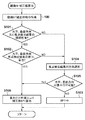
次に、図1Aおよび1Bを参照して、本実施形態のデジタルカメラにおける自動焦点検出(AF)動作について説明する。
AF処理の概要を説明した後、詳細な説明を行う。本実施形態でカメラMPU125はまず、焦点検出領域218ah、218bh、218chのそれぞれについて、位相差AFを適用して焦点ずれ量(デフォーカス量)と、デフォーカス量の信頼性とを求める。焦点検出領域218ah、218bh、218chの全てで所定の信頼性を有するデフォーカス量が得られていれば、カメラMPU125はデフォーカス量に基づいて最至近の被写体の合焦位置にフォーカスレンズ104を移動させる。
(Explanation of focus detection process flow)
Next, an automatic focus detection (AF) operation in the digital camera of this embodiment will be described with reference to FIGS. 1A and 1B.
After the outline of the AF process is described, a detailed description will be given. In this embodiment, the
一方、所定の信頼性を有するデフォーカス量が得られなかった焦点検出領域が存在する場合、カメラMPU125は、その焦点検出領域を包含するコントラストAF用の焦点検出領域について焦点評価値を取得する。カメラMPU125は、焦点評価値の変化とフォーカスレンズ104の位置の関係とに基づいて、位相差AFで得られたデフォーカス量に対応する被写体距離より至近側に被写体が存在するか判定する。そして、より至近側に被写体が存在すると判定された場合、焦点評価値の変化に基づく方向にフォーカスレンズ104を駆動する。
On the other hand, when there is a focus detection area where a defocus amount having a predetermined reliability cannot be obtained, the
なお、以前に焦点評価値が得られていない場合には焦点評価値の変化量を求めることができない。その場合、カメラMPU125は予め決められたデフォーカス量よりも大きく、かつ所定の信頼性を有するデフォーカス量が得られた焦点検出領域が存在する場合にはその中の最至近の被写体に合焦するようにフォーカスレンズ104を駆動する。所定の信頼性を有するデフォーカス量が得られていない場合、及び、予め決められたデフォーカス量よりも大きなデフォーカス量が得られていない場合、カメラMPU125はデフォーカス量に関係の無い所定量フォーカスレンズ104を駆動させる。これは、小さいデフォーカス量に基づいてフォーカスレンズ104を駆動した場合、次の焦点検出時に焦点評価値の変化を検出することが難しい可能性が高いからである。
Note that if the focus evaluation value has not been obtained before, the amount of change in the focus evaluation value cannot be obtained. In that case, if there is a focus detection area in which the
いずれかの方法により焦点検出を終えると、カメラMPU125は各種の補正値を算出し、焦点検出結果を補正する。そして、カメラMPU125は補正後の焦点検出結果に基づいてフォーカスレンズ104を駆動する。
When focus detection is finished by any method, the
以下、上述したAF処理の詳細を、図1Aおよび図1Bに示すフローチャートを用いて説明する。以下のAF処理動作は、他の主体が明記されている場合を除き、カメラMPU125が主体となって実行される。また、カメラMPU125がレンズMPU117にコマンド等を送信することによってレンズユニット100の駆動や制御を行う場合、説明を簡潔にするために動作主体をカメラMPU125として記載する場合がある。
S1でカメラMPU125は焦点検出領域を設定する。ここでは、位相差AF用、コントラストAF用とも、図5に示したような3か所の焦点検出領域が設定されるものとする。
Details of the AF process described above will be described below with reference to the flowcharts shown in FIGS. 1A and 1B. The following AF processing operations are executed mainly by the
In S1, the
S2において、カメラMPU125は、RAM125b内の至近判定フラグを1に設定する。
S3で、カメラMPU125は、撮像素子122を露光して画像信号を読み出し、画像処理回路124に位相差AF用の焦点検出領域218ah、218bh、218ch内の画像データに基づく位相差AF用の像信号を生成させる。また、画像処理回路124が生成したRAW画像データをTVAF部130に供給させ、TVAF部130でTVAF用の焦点検出領域219a、219b、219c内の画素データに基づく評価値を算出させる。なお、位相差AF用の像信号を生成する前に、画像処理回路124において撮影レンズのレンズ枠などによる光束のケラレによる射出瞳の非対称性を補正する処理(特開2010−117679号公報参照)を適用してもよい。TVAF部130が算出した焦点評価値は、カメラMPU125内のRAM125bに記憶される。
In S2, the
In S3, the
S4において、カメラMPU125は、信頼性のある焦点評価値のピーク(極大値)が検出されたか否かを判定する。信頼性のあるピークが検出された場合、カメラMPU125は、焦点検出処理を終えるために処理をS20に進める。なお、焦点評価値のピークの信頼性の算出方法に制限はないが、例えば、特開2010−78810号公報の図10から図13で説明されているような方法を用いればよい。具体的には、検出されたピークが山の頂点かどうかを、焦点評価値の最大値と最小値の差、一定値(SlopeThr)以上の傾きで傾斜している部分の長さ、および傾斜している部分の勾配をそれぞれの閾値と比較して判断する。全ての閾値を満たしていればピークは信頼性があると判定することができる。
In S4, the
本実施形態では、位相差AFとコントラストAFを併用している。そのため、同一の焦点検出領域や他の焦点検出領域で、より至近側の被写体の存在が確認されている場合には、信頼性のある焦点評価値ピークが検出された際であっても、焦点検出を終えずに処理をS5に進めてもよい。ただし、この場合、信頼性のある焦点評価値ピークに対応するフォーカスレンズ104の位置を記憶しておき、S5以降の処理で信頼性のある焦点検出結果が得られなかった場合に、記憶したフォーカスレンズ104位置を焦点検出結果とする。
In the present embodiment, phase difference AF and contrast AF are used in combination. For this reason, if the presence of a closer subject is confirmed in the same focus detection area or another focus detection area, the focus evaluation value peak is detected even when a reliable focus evaluation value peak is detected. The process may be advanced to S5 without finishing the detection. However, in this case, the position of the
S5において、位相差AF部129は、焦点検出領域218ch、218ah,218bhごとに、画像処理回路124から供給された一対の像信号のずれ量(位相差)を算出し、位相差を予め記憶されている換算係数を用いてデフォーカス量に変換する。ここでは、算出されたデフォーカス量の信頼性も判定し、所定の信頼性を有すると判定された焦点検出領域のデフォーカス量のみを、以後のAF処理で用いる。レンズ枠などによるケラレの影響により、デフォーカス量が大きくなるにつれて、一対の像信号間で検出される位相差は、より多くの誤差を含むようになる。そのため、得られたデフォーカス量が閾値より大きい場合、一対の像信号の形状の一致度が低い場合、像信号のコントラストが低い場合には、得られたデフォーカス量は所定の信頼性を有さない(信頼性が低い)と判定することができる。以下、得られたデフォーカス量が所定の信頼性を有すると判定された場合に「デフォーカス量が算出できた」と表現する。また、デフォーカス量が何らかの理由で算出できなかった場合や、デフォーカス量の信頼性が低いと判定された場合には「デフォーカス量が算出できない」と表現する。
In S5, the phase
S6でカメラMPU125は、S1で設定した位相差AF用の焦点検出領域218ah、218bh、218chの全てでデフォーカス量が算出できたか否か調べる。全ての焦点検出領域でデフォーカス量が算出できている場合、カメラMPU125は処理をS20に進め、算出されたデフォーカス量の中で、最も至近側にある被写体を示すデフォーカス量が算出された焦点検出領域に対して、縦横BP補正値(BP1)を算出する。ここで、最も至近側の被写体を選択する理由は、一般に、撮影者がピントを合わせたい被写体は、至近側に存在することが多いためである。また、縦横BP補正値(BP1)は、水平方向の被写体のコントラストに対して焦点検出を行った場合と、垂直方向の被写体のコントラストに対して焦点検出を行った場合の焦点検出結果の差を補正する値である。
In S6, the
一般的な被写体は、水平方向、垂直方向ともにコントラストを有しており、撮影された画像のピント状態の評価も、水平方向、垂直方向の両方向のコントラストを鑑みてなされる。一方で、上述の位相差検出方式のAFのように水平方向のみの焦点検出を行う場合、水平方向の焦点検出結果と撮影画像の水平方向、垂直方向の両方向のピント状態には誤差を生じる。この誤差は、撮影光学系の非点収差などにより発生する。縦横BP補正値(BP1)は、その誤差を補正するための補正値で、選択された焦点検出領域、フォーカスレンズ104の位置、ズーム状態を示す第1レンズ群101の位置などを考慮して算出される。算出方法の詳細については後述する。
A general subject has contrast in both the horizontal direction and the vertical direction, and the evaluation of the focus state of the captured image is also made in view of the contrast in both the horizontal direction and the vertical direction. On the other hand, when focus detection is performed only in the horizontal direction as in the AF of the phase difference detection method described above, an error occurs between the focus detection result in the horizontal direction and the focus state in both the horizontal and vertical directions of the captured image. This error is caused by astigmatism of the photographing optical system. The vertical / horizontal BP correction value (BP1) is a correction value for correcting the error, and is calculated in consideration of the selected focus detection region, the position of the
S21でカメラMPU125は、S20で補正値算出対象となった焦点検出領域に対して、垂直方向もしくは水平方向のコントラスト情報を用いて、色BP補正値(BP2)を算出する。色BP補正値(BP2)は、撮影光学系の色収差により発生するもので、焦点検出に用いる信号の色のバランスと撮影画像もしくは現像された画像に用いる信号の色のバランスとの差により生じる。例えば、本実施形態のコントラストAFでは、焦点評価値を緑(G)のカラーフィルタを有する画素(緑画素)出力に基づいて生成するため、主に緑色の波長の合焦位置を検出することになる。しかし、撮影画像は、RGB全色を用いて生成されるため、赤(R)や青(B)の合焦位置が緑(G)と異なる場合(軸上色収差が存在する場合)、焦点評価値による焦点検出結果とずれ(誤差)を生じる。その誤差を、補正するための補正値が、色BP補正値(BP2)である。色BP補正値(BP2)の算出方法の詳細は、後述する。
In S21, the
S22でカメラMPU125は、補正対象である焦点検出領域に対して、垂直方向もしくは水平方向で緑信号もしくは輝度信号Yのコントラスト情報を用いて、ある特定の色空間周波数BP補正値(BP3)を算出する。空間周波数BP補正値(BP3)は、撮影光学系の主に球面収差により発生するもので、焦点検出に用いる信号の評価周波数(帯域)と撮影画像を鑑賞する際の評価周波数(帯域)の差によって発生する。上述の通り焦点検出時の画像信号は第2のモードで撮像素子から読み出されているため、出力信号が加算や間引きされている。そのため、第1の読み出しモードで読み出された全画素の信号を用いて生成される撮影画像に対して、焦点検出に用いる出力信号は評価帯域が低くなる。その評価帯域の差により発生する焦点検出のずれを補正するのが空間周波数BP補正値(BP3)である。空間周波数BP補正値(BP3)の算出方法の詳細は、後述する。
In step S22, the
S23でカメラMPU125は、算出された3種の補正値(BP1、BP2、BP3)を用いて以下の式(1)により焦点検出結果DEF_Bを補正し、補正後の焦点検出結果DEF_Aを算出する。
DEF_A=DEF_B+BP1+BP2+BP3 (1)
In S23, the
DEF_A = DEF_B + BP1 + BP2 + BP3 (1)
本実施形態では、焦点検出結果を補正するための補正値を3段階に分けて、縦横(S20)、色(S21)、空間周波数(S22)の順番に、計算する。
まず、撮影画像の鑑賞時の評価が縦横両方向のコントラスト情報を用いられるのに対し、焦点検出は1方向のコントラスト情報を用いることに起因する誤差を、縦横BP補正値(BP1)として算出する。
In the present embodiment, the correction value for correcting the focus detection result is divided into three stages and is calculated in the order of vertical and horizontal (S20), color (S21), and spatial frequency (S22).
First, contrast in both vertical and horizontal directions is used for evaluation at the time of viewing a captured image, whereas focus detection calculates an error caused by using contrast information in one direction as a vertical and horizontal BP correction value (BP1).
次に、縦横BPの影響を切り離して、1方向のコントラスト情報において、撮影画像に用いられる信号の色と焦点検出時に用いられる信号の色による合焦位置の差を、色BP補正値(BP2)として算出する。
さらに、1方向のコントラスト情報で、緑もしくは輝度信号などのある特定の色に関して、撮影画像の鑑賞時と焦点検出時の評価帯域の差により発生する合焦位置の差を空間周波数BP補正値(BP3)として算出する。
このように、3種類の誤差を切り分けて算出することにより、演算量の低減、レンズもしくはカメラに記憶するデータ容量の低減を図っている。
Next, the influence of the vertical / horizontal BP is separated, and the difference in focus position between the color of the signal used for the captured image and the color of the signal used for focus detection in the contrast information in one direction is expressed as a color BP correction value (BP2). Calculate as
Further, with respect to a specific color such as green or a luminance signal in the contrast information in one direction, a spatial frequency BP correction value (a spatial frequency BP correction value ( BP3) is calculated.
In this way, by calculating the three types of errors separately, the amount of calculation is reduced and the data capacity stored in the lens or camera is reduced.
S24でカメラMPU125は、レンズMPU117を通じてフォーカスレンズ104を、式(1)で算出された補正後のデフォーカス量DEF_Aに基づいて駆動する。
In S <b> 24, the
S25でカメラMPU125は、フォーカスレンズ104の駆動に用いたデフォーカス量を算出した焦点検出領域を表す表示(AF枠表示)を、表示器126で例えばライブビュー画像に重畳表示させて、AF処理を終了する。
In S25, the
一方、S6でデフォーカス量が算出できなかった焦点検出領域が存在した場合、カメラMPU125は処理を図1BのS7に進める。S7でカメラMPU125は、至近判定フラグが1であるか否かを判定する。至近判定フラグが1なのは、AF動作が始まってからフォーカスレンズ駆動が一度も行われていない場合である。フォーカスレンズ駆動が行われていれば至近判定フラグは0となる。至近判定フラグが1である場合、カメラMPU125は、処理をS8に進める。
On the other hand, if there is a focus detection area where the defocus amount could not be calculated in S6, the
S8でカメラMPU125は、全ての焦点検出領域でデフォーカス量を算出できなかった場合、もしくは、算出されたデフォーカス量のうち、最も至近側の被写体の存在を示すデフォーカス量が所定の閾値A以下の場合には、処理をS9に進める。S9でカメラMPU125は、至近側に予め決められた量、フォーカスレンズを駆動する。
If the
ここでS8でYesの場合に、所定量のレンズ駆動を行う理由を説明する。まず、複数の焦点検出領域の中で、デフォーカス量が算出できた領域が無い場合とは、現時点では、ピント合わせを行うべき被写体が見つかっていない場合である。そのため、合焦不能であると判断する前に、全ての焦点検出領域に対して、ピント合わせを行うべき被写体の存在を確認するために、所定量のレンズ駆動を行い、後述する焦点評価値の変化を判定できるようにする。また、算出されたデフォーカス量の中で最も至近側の被写体の存在を示すデフォーカス量が所定の閾値A以下の場合とは、現時点で、ほぼ合焦状態の焦点検出領域が存在している場合である。このような状況では、デフォーカス量が算出できなかった焦点検出領域に、より至近側に、現時点では検出されていない被写体がある可能性を確認するために、所定量のレンズ駆動を行い、後述する焦点評価値の変化を判定できるようにする。
なお、S9でフォーカスレンズを駆動する所定量は、撮影光学系のF値やレンズ駆動量に対する撮像面上でのピント移動量の敏感度を鑑みて定めればよい。
Here, the reason why the predetermined amount of lens driving is performed in the case of Yes in S8 will be described. First, the case where there is no region where the defocus amount can be calculated among the plurality of focus detection regions is a case where no subject to be focused is found at the present time. Therefore, before determining that focusing is impossible, a predetermined amount of lens driving is performed to check the presence of a subject to be focused on in all focus detection areas, and a focus evaluation value described later is obtained. Enable to determine changes. Also, when the defocus amount indicating the presence of the closest subject in the calculated defocus amount is equal to or smaller than the predetermined threshold A, there is a focus detection region that is almost in focus at the present time. Is the case. In such a situation, a predetermined amount of lens drive is performed in order to confirm that there is a subject that is not detected at the present time closer to the focus detection area where the defocus amount could not be calculated. It is possible to determine a change in focus evaluation value.
The predetermined amount for driving the focus lens in S9 may be determined in view of the sensitivity of the focus movement amount on the imaging surface to the F value of the photographing optical system and the lens driving amount.
一方で、S8でNoの場合、すなわち、算出されたデフォーカス量の中で最も至近側の被写体の存在を示すデフォーカス量が所定の閾値Aより大きい場合には、S10に進む。この場合には、デフォーカス量が算出できた焦点検出領域は存在するものの、その焦点検出領域は合焦状態ではない場合である。そのため、S10でカメラMPU125は、算出されたデフォーカス量の中で最も至近側の被写体の存在を示すデフォーカス量に基づき、レンズ駆動を行う。
S9もしくはS10にてレンズ駆動を行った後、カメラMPU125は処理をS11に進め、至近判定フラグを0に設定して、図1AのS3に処理を戻す。
On the other hand, in the case of No in S8, that is, when the defocus amount indicating the presence of the closest subject in the calculated defocus amount is larger than the predetermined threshold A, the process proceeds to S10. In this case, there is a focus detection area where the defocus amount can be calculated, but the focus detection area is not in focus. Therefore, in step S10, the
After driving the lens in S9 or S10, the
S7で、至近判定フラグが1でない(0である)場合、カメラMPU125は処理をS12に進める。S12でカメラMPU125は、デフォーカス量が算出できなかった焦点検出領域に対応したTVAF用の焦点検出領域の焦点評価値が、レンズ駆動前後で、所定の閾値B以上変化したか否かを判断する。焦点評価値は増加する場合も減少する場合もあるが、S12では焦点評価値の変化量の絶対値が所定の閾値B以上であるか否かを判断する。
If the closeness determination flag is not 1 (0) in S7, the
ここで、焦点評価値の変化量の絶対値が所定の閾値B以上である場合とは、デフォーカス量は算出できないものの、焦点評価値の増減により、被写体のボケ状態の変化を検出できたことを意味している。そのため、本実施形態では、位相差AFによるデフォーカス量が検出できない場合でも、焦点評価値の増減に基づいて被写体の存在を判定し、AF処理を継続する。これにより、デフォーカス量が大きく、位相差AFでは検出できない被写体に対して、焦点調節を行うことができる。 Here, when the absolute value of the change amount of the focus evaluation value is equal to or greater than the predetermined threshold B, the defocus amount cannot be calculated, but the change in the blur state of the subject can be detected by increasing or decreasing the focus evaluation value. Means. Therefore, in the present embodiment, even when the defocus amount due to the phase difference AF cannot be detected, the presence of the subject is determined based on the increase / decrease of the focus evaluation value, and the AF process is continued. As a result, focus adjustment can be performed on a subject that has a large defocus amount and cannot be detected by phase difference AF.
ここで、判定に用いられる所定の閾値Bは、レンズ駆動量に応じて変更する。レンズ駆動量が大きい場合は、小さい場合よりも閾値Bに大きい値を設定する。これは、被写体が存在する場合には、レンズ駆動量の増加に応じて、焦点評価値の変化量も増加するためである。これらのレンズ駆動量ごとの閾値Bは、EEPROM125cに記憶されている。
Here, the predetermined threshold B used for the determination is changed according to the lens driving amount. When the lens driving amount is large, a larger value is set for the threshold B than when the lens driving amount is small. This is because when the subject exists, the amount of change in the focus evaluation value increases as the lens driving amount increases. The threshold value B for each lens driving amount is stored in the
焦点評価値の変化量の絶対値が閾値B以上である場合、カメラMPU125は処理をS13に進め、焦点評価値の変化量が閾値B以上ある焦点検出領域が、無限遠側被写体の存在を示す焦点検出領域のみであるか否かを判定する。焦点検出領域が無限遠側被写体の存在を示す場合とは、レンズ駆動の駆動方向が至近方向で焦点評価値が減少、もしくは、レンズ駆動の駆動方向が無限遠方向で焦点評価値が増加した場合である。
When the absolute value of the change amount of the focus evaluation value is equal to or greater than the threshold value B, the
焦点評価値の変化量が閾値B以上である焦点検出領域が、無限遠側被写体の存在を示す焦点検出領域のみでない場合、カメラMPU125は処理をS14に進め、至近側に所定量のレンズ駆動を行う。これは、焦点評価値の変化量が閾値B以上ある焦点検出領域の中に、至近側被写体の存在を示す焦点検出領域があるためである。なお、至近側を優先する理由は上述のとおりである。
When the focus detection area where the change amount of the focus evaluation value is equal to or greater than the threshold B is not only the focus detection area indicating the presence of the infinity side subject, the
一方、S13において、焦点評価値の変化量が閾値B以上ある焦点検出領域が、無限遠側被写体の存在を示す焦点検出領域のみである場合、カメラMPU125は処理をS15に進める。S15でカメラMPU125は、デフォーカス量が算出できた焦点検出領域が存在するか否かを判定する。デフォーカス量が算出できた焦点検出領域が存在する場合(S15でYes)には、焦点評価値による無限遠側被写体の存在よりも、位相差AFの結果を優先するため、カメラMPU125は、処理を図1AのS20に進める。
On the other hand, in S13, when the focus detection area where the change amount of the focus evaluation value is greater than or equal to the threshold B is only the focus detection area indicating the presence of the infinity side subject, the
デフォーカス量が算出できた焦点検出領域が存在しない場合(S15でNo)には、被写体の存在を示す情報が、焦点評価値の変化のみである。そのため、カメラMPU125は、焦点評価利の変化に基づいて、S16で無限遠側に所定量のレンズ駆動を行い、処理を図1AのS3に戻す。
When there is no focus detection area where the defocus amount can be calculated (No in S15), the information indicating the presence of the subject is only the change in the focus evaluation value. Therefore, the
S14及びS16で行うレンズ駆動の所定量は、位相差AFで検出可能なデフォーカス量を鑑みて決めればよい。被写体によって検出可能なデフォーカス量は異なるが、焦点検出不可能な状態からのレンズ駆動で、被写体を検出できずに通り過ぎてしまうことがないようなレンズ駆動量を予め設定しておく。 The predetermined amount of lens driving performed in S14 and S16 may be determined in view of the defocus amount that can be detected by the phase difference AF. Although the defocus amount that can be detected differs depending on the subject, a lens drive amount is set in advance so that the subject cannot be detected and passed by the lens drive from a state where the focus cannot be detected.
焦点評価値の変化量の絶対値が所定の閾値B未満である場合(S12でNo)、カメラMPU125は処理をS17に進め、デフォーカス量が算出できた焦点検出領域の有無を判定する。デフォーカス量が算出できた焦点検出領域が無い場合、カメラMPU125は、処理をS18に進め、予め定められた定点にレンズを駆動した後、さらに処理をS19に進め、表示器126に非合焦表示を行ってAF処理を終了する。これは、デフォーカス量が算出できた焦点検出領域が無く、レンズ駆動の前後で焦点評価値の変化がある焦点検出領域も無い場合である。このような場合、被写体の存在を示す情報が全く無いため、カメラMPU125は合焦不能と判定してAF処理を終了する。
If the absolute value of the change amount of the focus evaluation value is less than the predetermined threshold B (No in S12), the
一方、S17で、デフォーカス量が算出できた焦点検出領域が有る場合、カメラMPU125は処理を図1AのS20に進め、検出されたデフォーカス量の補正を行い(S20〜S23)、S24で合焦位置へフォーカスレンズ104を駆動する。その後、カメラMPU125はS25で表示器126に合焦表示を行い、AF処理を終了する。
On the other hand, if there is a focus detection area in which the defocus amount can be calculated in S17, the
(縦横BP補正値の算出方法)
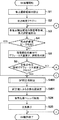
次に、図7から図8(b)を用いて、図1のS20で行う縦横BP補正値(BP1)の算出方法について説明する。図7は、縦横BP補正値(BP1)の算出処理の詳細を示すフローチャートである。
S100で、カメラMPU125は縦横BP補正情報を取得する。縦横BP補正情報は、水平方向(第1の方向)の合焦位置に対する垂直方向(第2の方向)の合焦位置の差分情報である。本実施形態において縦横BP補正情報はレンズユニット100のレンズメモリ118に予め記憶されており、カメラMPU125は、レンズMPU117に要求して取得するものとする。しかし、カメラRAM125bの不揮発性領域に、レンズユニットの識別情報と対応付けて記憶されていてもよい。
(Calculation method of vertical / horizontal BP correction value)
Next, a method for calculating the vertical / horizontal BP correction value (BP1) performed in S20 of FIG. 1 will be described with reference to FIGS. FIG. 7 is a flowchart showing details of the calculation process of the vertical / horizontal BP correction value (BP1).
In S100, the
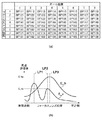
図8(a)に、縦横BP補正情報の例を示す。ここでは、図6の中央の焦点検出領域219a、218ahに対応した縦横BP補正情報の例を示しているが、他の焦点検出領域219c、218chおよび219b、218bhについても縦横BP補正情報を記憶している。ただし、撮影光学系の光軸を挟んで対称な位置に存在する焦点検出領域の焦点検出補正値は設計上は等しい。本実施形態において、焦点検出領域219c、218chと219b、218bhとはこのような対象関係を満たすため、一方についてのみ縦横BP補正情報を記憶してもよい。また、焦点検出領域の位置によって補正値が大きく変化しない場合には、共通の値として記憶してもよい。
FIG. 8A shows an example of vertical / horizontal BP correction information. Here, an example of the vertical and horizontal BP correction information corresponding to the central
図8(a)に示す例では、撮影光学系のズーム位置(画角)とフォーカスレンズ位置(合焦距離)を8つのゾーンに分割し、ゾーンごとに焦点検出補正値BP111〜BP188を記憶している。分割ゾーン数が多いほど撮影光学系の第1レンズ群101の位置およびフォーカスレンズ104の位置に応じた高精度な補正値が得られる。また、縦横BP補正情報は、コントラストAF、位相差AFの両方に用いることができる。
In the example shown in FIG. 8A, the zoom position (field angle) and focus lens position (focus distance) of the photographing optical system are divided into eight zones, and focus detection correction values BP111 to BP188 are stored for each zone. ing. As the number of divided zones increases, a highly accurate correction value corresponding to the position of the
S100でカメラMPU125は、補正対象となっている焦点検出結果に応じたズーム位置、フォーカスレンズ位置に対応した補正値を取得する。
S101でカメラMPU125は、補正対象となっている焦点検出領域において、水平方向、垂直方向のいずれの方向に対しても信頼性のある焦点検出結果が得られているかを判定する。焦点検出結果の信頼性の判定の方法については、位相差AFについてもコントラストAFについても上述した通りである。本実施形態の位相差AFは水平方向の焦点検出しか行っていないため、水平方向、垂直方向の両方向に信頼性のある焦点検出結果が得られるのはコントラストAFである。そのため、縦横BP補正値に関する以後の説明は、コントラストAFを想定した説明を行うが、位相差AFの焦点検出を水平、垂直の両方向で行う場合も、同様の処理を行えばよい。S101で、水平方向、垂直方向のいずれの焦点検出結果も信頼性があると判定された場合、カメラMPU125は、処理をS102に進める。
In S100, the
In step S101, the
S102でカメラMPU125は、水平方向の焦点検出結果と垂直方向の焦点検出結果の差が、妥当であるか否かを判定する。これは、遠い距離の被写体と近い距離の被写体を焦点検出領域内に含んだ際に生じる遠近競合の問題に対応するために行う処理である。例えば、遠い被写体が水平方向にコントラストを有し、近い被写体が垂直方向にコントラストを有するような場合、撮影光学系の非点収差などにより発生する誤差よりも絶対値が大きかったり、符号が反対の焦点検出結果の差が生じたりする場合がある。カメラMPU125は、水平方向の焦点検出結果と垂直方向の焦点検出結果の差が予め定めた判定値Cより大きい場合には差が妥当でない(遠近競合している)と判定する。そして、より至近側の焦点検出結果を示す方向として水平方向もしくは垂直方向を選択し、処理をS104に進める。なお、判定値Cは、上述の理由から、収差などで発生しうる差を大きく超える値を一意に決めてもよいし、S100で得られた補正情報を用いて設定してもよい。
In S102, the
S102で水平方向の焦点検出結果と垂直方向の焦点検出結果の差が妥当であると判定された場合、カメラMPU125は、処理をS106に進める。
If it is determined in S102 that the difference between the focus detection result in the horizontal direction and the focus detection result in the vertical direction is appropriate, the
一方で、S101で水平方向、もしくは垂直方向の一方向にのみ信頼性が有る場合や、S102で水平方向もしくは垂直方向の一方向のみが選択された場合、カメラMPU125は処理をS104に進める。S104でカメラMPU125は焦点検出結果の方向選択を行う。信頼性のある焦点検出結果を算出した方向や、遠近競合判定で、より至近側にある被写体に対応した焦点検出結果を算出した方向を選択する。
On the other hand, if there is reliability in only one horizontal or vertical direction in S101, or if only one horizontal or vertical direction is selected in S102, the
次にカメラMPU125は、S105で、水平方向、垂直方向の重み付けが可能であるか否かを判定する。S105が実行される場合、焦点評価値の信頼性や遠近競合の観点で、水平方向、垂直方向の両方向に対して信頼性のある焦点検出結果が得られていないが、縦横BP補正値を算出するための判定を改めて行う。この理由を、図8(b)を用いて、詳細に説明する。
Next, in step S105, the
図8(b)は、選択された焦点検出領域のフォーカスレンズ104の位置と焦点評価値の関係例を示す図である。図中の曲線E_h、E_vは、コントラストAFで検出された水平方向の焦点評価値と垂直方向の焦点評価値の変化を示す。また、LP1、LP2、LP3は、それぞれフォーカスレンズ位置を示す。図8(b)では、水平方向の焦点評価値E_hから信頼性のある焦点検出結果としてLP3が得られ、垂直方向の焦点評価値E_vから信頼性のある焦点検出結果としてLP1が得られた場合を示している。LP1とLP3とが大きく異なっているため遠近競合状態であると判定され、より至近側の焦点検出結果である水平方向の焦点検出結果LP3がS104で選択される。
FIG. 8B is a diagram showing an example of the relationship between the position of the
このような状況で、S105でカメラMPU125は、選択されている水平方向の焦点検出結果LP3近傍に、垂直方向の焦点検出結果が存在しないか否かを判定する。図8(b)のような状況ではLP2が存在するため、カメラMPU125は、水平、垂直方向の重み付けが可能であると判定して処理をS106に進め、焦点検出結果LP3の補正値を、焦点検出結果LP2の影響を考慮に入れて算出する。
In such a situation, in S105, the
S100において縦横BP補正情報として図8(a)の1要素であるBP1_Bを取得しており、図8(b)におけるLP3における水平方向の焦点評価値がE_hp、LP2における垂直方向の焦点評価値がE_vpであるとする。この場合、S106でカメラMPU125は、焦点評価値の合計に対する、補正する方向と直交する方向における焦点評価値の割合に基づき、縦横BP補正値BP1を以下の式(2)に従って算出する。
BP1=BP1_B×E_vp/(E_vp+E_hp)×(+1) (2)
In S100, BP1_B, which is one element of FIG. 8A, is acquired as the vertical and horizontal BP correction information, the horizontal focus evaluation value in LP3 in FIG. 8B is E_hp, and the vertical focus evaluation value in LP2 is the vertical focus evaluation value. It is assumed that E_vp. In this case, in S106, the
BP1 = BP1_B × E_vp / (E_vp + E_hp) × (+1) (2)
本実施形態では、水平方向の焦点検出結果に対する補正値を算出するため、式(2)を用いて補正値BP1を算出するが、垂直方向の焦点検出結果を補正する場合には、以下の式(3)で算出することができる。
BP1=BP1_B×E_hp/(E_vp+E_hp)×(−1) (3)
In the present embodiment, in order to calculate a correction value for the focus detection result in the horizontal direction, the correction value BP1 is calculated using Equation (2). However, when correcting the focus detection result in the vertical direction, the following equation is used. It can be calculated in (3).
BP1 = BP1_B × E_hp / (E_vp + E_hp) × (−1) (3)
S102で水平方向の焦点検出結果と垂直方向の焦点検出結果の差が妥当であると判定された場合、至近側の焦点検出結果が水平方向の検出結果であれば式(2)を、垂直方向の検出結果であれば式(3)を用いて補正値BP1を算出する。 When it is determined in S102 that the difference between the focus detection result in the horizontal direction and the focus detection result in the vertical direction is appropriate, if the focus detection result on the near side is the detection result in the horizontal direction, Equation (2) is obtained. If the detection result is, the correction value BP1 is calculated using Equation (3).
式(2)、式(3)から自明であるように、焦点評価値が大きいという情報を、被写体に含まれるコントラスト情報が多いと判定して、縦横BP補正値(BP1)を算出する。上述の通り、縦横BP補正情報は、
(垂直方向にのみコントラスト情報をもつ被写体の焦点検出位置)−(水平方向にのみコントラスト情報を持つ被写体の焦点検出位置)
である。そのため、水平方向の焦点検出結果を補正する補正値BP1と垂直方向の焦点検出結果を補正する補正値BP1の符号は反対となる。S106の処理を終えるとカメラMPU125は、縦横BP補正値算出処理を終了する。
As is obvious from Expressions (2) and (3), information indicating that the focus evaluation value is large is determined to be a large amount of contrast information included in the subject, and the vertical and horizontal BP correction value (BP1) is calculated. As described above, the vertical and horizontal BP correction information is
(Focus detection position of a subject having contrast information only in the vertical direction)-(Focus detection position of a subject having contrast information only in the horizontal direction)
It is. Therefore, the signs of the correction value BP1 for correcting the focus detection result in the horizontal direction and the correction value BP1 for correcting the focus detection result in the vertical direction are opposite. When the process of S106 is completed, the
一方、選択されている水平方向の焦点検出結果LP3近傍に、垂直方向の焦点検出結果が存在しないとS105で判定された場合、カメラMPU125は処理をS103に進める。S103でカメラMPU125は、被写体に含まれるコントラスト情報が概ね1方向のみであると判断されるため、BP1=0とし、縦横BP補正値算出処理を終了する。
On the other hand, if it is determined in S105 that there is no vertical focus detection result in the vicinity of the selected horizontal focus detection result LP3, the
このように、本実施形態では、異なる方向における被写体のコントラスト情報に応じて補正値を算出するため、被写体のパターンに応じた高精度な補正値算出を行うことができる。なお、図8(b)では、被写体が遠近競合している場合について説明したが、水平方向と垂直方向に1つずつ極大値が検出されており、片方の焦点検出結果に信頼性が無い場合も、同様の考え方で補正値を算出する。 Thus, in this embodiment, since the correction value is calculated according to the contrast information of the subject in different directions, it is possible to calculate the correction value with high accuracy according to the pattern of the subject. In FIG. 8B, the case where the subject is competing for perspective has been described, but the maximum value is detected one by one in the horizontal direction and the vertical direction, and the focus detection result on one side is not reliable. Also, the correction value is calculated in the same way.
ただし、S106での補正値算出方法はこれに限らない。例えば、本実施形態の位相差AFのように、水平方向のみ焦点検出が行える場合には、被写体の水平方向と垂直方向のコントラストの情報量は同量であると仮定して、補正値を算出してもよい。その場合には、上述の式(2)、式(3)において、E_hp=E_vp=1を代入することにより補正値を算出することができる。このような処理を行うことにより、補正精度は落ちるが、補正値演算の負荷を減らすことができる。 However, the correction value calculation method in S106 is not limited to this. For example, when focus detection can be performed only in the horizontal direction as in the phase difference AF of the present embodiment, the correction value is calculated on the assumption that the amount of contrast information in the horizontal direction and the vertical direction of the subject is the same. May be. In that case, the correction value can be calculated by substituting E_hp = E_vp = 1 in the above-described equations (2) and (3). By performing such processing, the correction accuracy is reduced, but the load of correction value calculation can be reduced.
上述の説明では、コントラストAFの焦点検出結果に対して説明したが、位相差AFの焦点検出結果に対しても同様の処理を行うことが可能である。補正値算出の際の重み付けの係数として、位相差AFの相関演算で算出される相関量の変化量を用いればよい。これは、被写体の明暗差が大きい場合や明暗差のあるエッジの数が多い場合など、被写体のコントラスト情報が多ければ多いほど、相関量の変化量も大きくなることを利用している。同様の関係が得られる評価値であれば、相関量の変化量に限らず、種々の評価値を用いてよい。 In the above description, the focus detection result of contrast AF has been described, but the same processing can be performed on the focus detection result of phase difference AF. As a weighting coefficient when calculating the correction value, a change amount of the correlation amount calculated by the correlation calculation of the phase difference AF may be used. This utilizes the fact that the amount of change in the correlation amount increases as the contrast information of the subject increases, such as when the contrast of the subject is large or the number of edges having the contrast is large. As long as the evaluation value can obtain the same relationship, various evaluation values may be used without being limited to the change amount of the correlation amount.
このように、縦横BP補正値を用いて焦点検出結果を補正することにより、被写体の方向ごとのコントラスト情報の量によらず、高精度な焦点検出を行うことができる。また、水平方向、垂直方向の補正値を図8(a)に示したような共通の補正情報を用いて算出しているため、方向ごとに各々の補正値を記憶する場合に比べて、補正情報の記憶容量を低減することができる。 As described above, by correcting the focus detection result using the vertical and horizontal BP correction values, it is possible to perform highly accurate focus detection regardless of the amount of contrast information for each direction of the subject. Further, since the correction values in the horizontal direction and the vertical direction are calculated using the common correction information as shown in FIG. 8A, the correction values are corrected as compared with the case where each correction value is stored for each direction. The storage capacity of information can be reduced.
また、方向ごとの焦点検出結果が大きく異なる場合には、これらの焦点検出結果を用いた縦横BP補正値の算出を行わないことにより、遠近競合の影響を低減することができる。さらに、遠近競合が想定される場合においても、方向ごとの焦点評価値の大小により補正値の重みづけを行うことにより、より高精度な補正を行うことができる。 In addition, when the focus detection results for each direction are greatly different, the influence of perspective conflict can be reduced by not calculating the vertical and horizontal BP correction values using these focus detection results. Furthermore, even when perspective conflict is assumed, more accurate correction can be performed by weighting the correction value based on the magnitude of the focus evaluation value for each direction.
(色BP補正値の算出方法)
次に、図9(a)および図9を用いて、図1のS21で行う色BP補正値(BP2)の算出方法について説明する。図9(a)は、色BP補正値(BP2)の算出処理の詳細を示すフローチャートである。
S200で、カメラMPU125は色BP補正情報を取得する。色BP補正情報は、緑(G)の信号を用いて検出される合焦位置に対する他の色(赤(R)、青(B))の信号を用いて検出される合焦位置の差分情報である。本実施形態において色BP補正情報はレンズユニット100のレンズメモリ118に予め記憶されており、カメラMPU125は、レンズMPU117に要求して取得するものとするが、カメラRAM125bの不揮発性領域に記憶されていてもよい。
(Calculation method of color BP correction value)
Next, a method for calculating the color BP correction value (BP2) performed in S21 of FIG. 1 will be described with reference to FIG. 9A and FIG. FIG. 9A is a flowchart showing details of the calculation process of the color BP correction value (BP2).
In step S200, the
分割ゾーン数が多いほど撮影光学系の第1レンズ群101の位置およびフォーカスレンズ104の位置に応じた高精度な補正値が得られる。また、色BP補正情報は、コントラストAF、位相差AFの両方に用いることができる。
As the number of divided zones increases, a highly accurate correction value corresponding to the position of the
S200でカメラMPU125は、補正対象となっている焦点検出結果に応じたズーム位置、フォーカスレンズ位置に対応した補正値を取得する。
S201でカメラMPU125は、色BP補正値を算出する。S200で、図9(b)の1要素としてBP_R、図9(c)の1要素としてBP_Bを取得している場合、カメラMPU125は、色BP補正値BP2を以下の式(4)に従って算出する。
BP2=K_R×BP_R+K_B×BP_B (4)
In S200, the
In step S201, the
BP2 = K_R × BP_R + K_B × BP_B (4)
ここで、K_RおよびK_Bは、各色の補正情報に対する係数である。被写体に含まれる緑(G)情報に対する赤(R)や青(B)の情報の大小関係と相関がある値で、赤い色を多く含む被写体に対しては、K_Rが大きな値を取り、青い色を多く含む被写体に対しては、K_Bが大きな値を取る。緑色を多く含む被写体に対しては、K_R、K_B共に小さい値を取る。K_R、K_Bは、被写体として代表的な分光情報に基づき、予め設定しておけばよい。被写体の分光情報を検出できる場合には、被写体の分光情報に応じてK_R、K_Bを設定すればよい。S202で色BP補正値の算出を終えると、カメラMPU125は、色BP補正値算出処理を終了する。
Here, K_R and K_B are coefficients for the correction information of each color. For a subject that contains many red colors, K_R takes a large value and is blue for a value that correlates with the magnitude relationship of red (R) and blue (B) information with respect to green (G) information contained in the subject. For a subject that contains many colors, K_B takes a large value. For a subject containing a lot of green, both K_R and K_B take small values. K_R and K_B may be set in advance based on spectral information representative of the subject. When the spectral information of the subject can be detected, K_R and K_B may be set according to the spectral information of the subject. When the calculation of the color BP correction value is completed in S202, the
なお、本実施形態では、補正値を図8(a)や図9のように焦点検出領域ごとにテーブル形式で記憶するものとしたが、補正値の記憶方法については、これに限らない。例えば、撮像素子と撮影光学系の光軸との交点を原点とし、撮像装置の水平方向、垂直方向をX軸、Y軸とした座標を設定し、焦点検出領域の中心座標における補正値をXとYの関数で求めてもよい。この場合、焦点検出補正値として記憶すべき情報量を削減することができる。 In the present embodiment, correction values are stored in a table format for each focus detection area as shown in FIG. 8A and FIG. 9, but the correction value storage method is not limited to this. For example, the coordinates where the intersection of the imaging element and the optical axis of the imaging optical system is set as the origin, the horizontal and vertical directions of the imaging device are set as the X axis and the Y axis are set, and the correction value at the center coordinate of the focus detection region is set as X And a function of Y. In this case, the amount of information to be stored as the focus detection correction value can be reduced.
また、本実施形態では、縦横BP補正情報や色BP補正情報を用いて算出する焦点検出に用いる補正値を、被写体のパターンの持つ空間周波数情報によらないものとして算出した。そのため、記憶するべき補正情報の量を増やすことなく高精度な補正を行うことができる。しかしながら、補正値の算出方法は、これに限らない。後述する空間周波数BP補正値の算出方法と同様に、空間周波数ごとの縦横BP補正情報や色BP補正情報を用いて、被写体の空間周波数成分に合わせた補正値を算出してもよい。 In the present embodiment, the correction value used for focus detection calculated using the vertical / horizontal BP correction information and the color BP correction information is calculated based on the spatial frequency information of the subject pattern. Therefore, highly accurate correction can be performed without increasing the amount of correction information to be stored. However, the correction value calculation method is not limited to this. Similar to the method of calculating the spatial frequency BP correction value described later, a correction value that matches the spatial frequency component of the subject may be calculated using vertical / horizontal BP correction information and color BP correction information for each spatial frequency.
(空間周波数BP補正値の算出方法)
次に、図10(a)から図10(c)を用いて、図1のS22で行う空間周波数BP補正値(BP3)の算出方法について説明する。図10(a)は、空間周波数BP補正値(BP3)の算出処理の詳細を示すフローチャートである。
S300で、カメラMPU125は空間周波数BP補正情報を取得する。空間周波数BP補正情報は、被写体の空間周波数ごとの撮影光学系の結像位置に関する情報である。本実施形態において空間周波数BP補正情報はレンズユニット100のレンズメモリ118に予め記憶されており、カメラMPU125は、レンズMPU117に要求して取得するものとするが、カメラRAM125bの不揮発性領域に記憶されていてもよい。
(Calculation method of spatial frequency BP correction value)
Next, the calculation method of the spatial frequency BP correction value (BP3) performed in S22 of FIG. 1 will be described using FIGS. 10 (a) to 10 (c). FIG. 10A is a flowchart showing details of the calculation processing of the spatial frequency BP correction value (BP3).
In S300, the
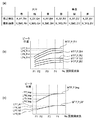
撮影光学系のデフォーカスMTF(Modulation Transfer Function)を示す図10(b)を用いて、空間周波数BP補正情報の例を説明する。図10(b)の横軸はフォーカスレンズ104の位置を、縦軸はMTFの強度を示している。図10(b)に描かれている4種の曲線は、空間周波数ごとのMTF曲線で、MTF1、MTF2、MTF3、MTF4の順に、空間周波数が低い方から高い方に変化した場合を示している。空間周波数F1(lp/mm)のMTF曲線がMTF1と対応し、同様に、空間周波数F2,F3,F4(lp/mm)とMTF2、MTF3、MTF4が対応する。また、LP4、LP5、LP5、LP6は、各デフォーカスMTF曲線の極大値に対応するフォーカスレンズ104位置を示している。なお、記憶されている空間周波数BP補正情報は図10(b)の曲線を離散的にサンプリングしたものである。一例として本実施形態では、1つのMTF曲線に対して10個のフォーカスレンズ位置に対してMTFデータがサンプリングされており、例えば、MTF1に対しては、MTF1(n)(1≦n≦10)として10個のデータを記憶している。
An example of the spatial frequency BP correction information will be described with reference to FIG. 10B showing a defocus MTF (Modulation Transfer Function) of the photographing optical system. In FIG. 10B, the horizontal axis indicates the position of the
空間周波数BP補正情報は、縦横BP補正情報や色BP補正情報と同様、焦点検出領域の位置ごとに撮影光学系のズーム位置(画角)とフォーカスレンズ位置(合焦距離)を8つのゾーンに分割し、ゾーンごとに記憶する。分割ゾーン数が多いほど撮影光学系の第1レンズ群101の位置およびフォーカスレンズ104の位置に応じた高精度な補正値が得られる。また、空間周波数BP補正情報は、コントラストAF、位相差AFの両方に用いることができる。
Spatial frequency BP correction information, like vertical and horizontal BP correction information and color BP correction information, has eight zones for the zoom position (view angle) and focus lens position (focus distance) of the photographing optical system for each position of the focus detection area. Divide and store for each zone. As the number of divided zones increases, a highly accurate correction value corresponding to the position of the
S300でカメラMPU125は、補正対象となっている焦点検出結果に応じたズーム位置、フォーカスレンズ位置に対応した補正値を取得する。
S301でカメラMPU125は、補正対象となっている焦点検出領域において、コントラストAFや位相差AFを行う際に用いられる信号の帯域を算出する。本実施形態でカメラMPU125は、被写体、撮影光学系、撮像素子のサンプリング周波数、評価に用いるデジタルフィルタの影響を鑑みて、AF評価帯域を算出する。AF評価帯域の算出方法は、後述する。
In S300, the
In step S <b> 301, the
次に、S302でカメラMPU125は、撮影画像に用いられる信号の帯域を算出する。S302のAF評価帯域の算出と同様にカメラMPU125は、被写体、撮影光学系、および撮像素子の周波数特性、撮影画像の鑑賞者の評価帯域の影響を鑑みて、撮影画像評価帯域を算出する。
Next, in S302, the
図11を用いて、S301、S302で行うAF評価帯域(第2の評価帯域)、撮影画像評価帯域(第1の評価帯域)の算出について説明する。図11は、いずれも空間周波数ごとの強度を示しており、横軸に空間周波数、縦軸に強度を示している。
図11(a)は、被写体の空間周波数特性(I)を示している。横軸上のF1、F2,F3、F4は、図10(b)のMTF曲線(MTF1〜MTF4)と対応した空間周波数である。また、Nqは、撮像素子122の画素ピッチによりきまるナイキスト周波数を示している。F1からF4とNqについては、以後説明する図11(b)から図11(f)にも同様に示している。本実施形態では、被写体の空間周波数特性(I)は、事前に記憶した代表値を用いる。図11(a)では、被写体の空間周波数特性(I)は連続した曲線で描かれているが、空間周波数F1,F2,F3,F4に対応した離散値I(n)(1≦n≦4)を有する。
The calculation of the AF evaluation band (second evaluation band) and the captured image evaluation band (first evaluation band) performed in S301 and S302 will be described with reference to FIG. FIG. 11 shows the intensity for each spatial frequency, with the horizontal axis indicating the spatial frequency and the vertical axis indicating the intensity.
FIG. 11A shows the spatial frequency characteristic (I) of the subject. F1, F2, F3, and F4 on the horizontal axis are spatial frequencies corresponding to the MTF curves (MTF1 to MTF4) in FIG. Nq represents the Nyquist frequency determined by the pixel pitch of the
また、本実施形態では、被写体の空間周波数特性として予め記憶された代表値を用いたが、焦点検出を行う被写体に応じて、用いる被写体の空間周波数特性を変更してもよい。撮影した画像信号にFFT処理などを適用することにより、被写体の空間周波数情報(パワースペクトル)を得ることができる。この場合、演算処理が増加するが、実際に焦点検出する被写体に応じた補正値を算出できるため、高精度な焦点検出が可能となる。また、より簡易的に、被写体のコントラスト情報の大小によって、予め記憶された数種の空間周波数特性を使い分けてもよい。 In this embodiment, the representative value stored in advance as the spatial frequency characteristic of the subject is used. However, the spatial frequency characteristic of the subject to be used may be changed according to the subject for which focus detection is performed. The spatial frequency information (power spectrum) of the subject can be obtained by applying FFT processing or the like to the captured image signal. In this case, the calculation processing increases, but since a correction value corresponding to the subject for which focus detection is actually performed can be calculated, focus detection with high accuracy is possible. Further, several types of spatial frequency characteristics stored in advance may be properly used depending on the magnitude of the contrast information of the subject.
図11(b)は、撮影光学系の空間周波数特性(O)である。この情報は、レンズMPU117を通じて得てもよいし、カメラ内のRAM125bに記憶しておいてもよい。記憶する情報は、デフォーカス状態ごとの空間周波数特性でもよいし、合焦時の空間周波数特性のみでもよい。空間周波数BP補正値は合焦近傍で算出するため、合焦時の空間周波数特性を用いれば、高精度に補正を行うことができる。ただし、演算負荷は増えるものの、デフォーカス状態ごとの空間周波数特性を用いると、より高精度に焦点調節を行うことができる。どのデフォーカス状態の空間周波数特性を用いるかについては、位相差AFにより得られるデフォーカス量を用いて選択すればよい。
FIG. 11B is a spatial frequency characteristic (O) of the photographing optical system. This information may be obtained through the
図11(b)で撮影光学系の空間周波数特性(O)は連続した曲線で描かれているが、空間周波数F1,F2,F3,F4に対応した離散値O(n)(1≦n≦4)を有する。
図11(c)は、光学ローパスフィルタ121の空間周波数特性(L)である。この情報は、カメラ内のRAM125bに記憶されている。図11(c)では、光学ローパスフィルタ121の空間周波数特性(L)は、連続した曲線で描かれているが、空間周波数F1,F2,F3,F4に対応した離散値L(n)(1≦n≦4)を有する。
In FIG. 11B, the spatial frequency characteristic (O) of the photographing optical system is drawn as a continuous curve, but the discrete value O (n) (1 ≦ n ≦ 1) corresponding to the spatial frequencies F1, F2, F3, and F4. 4).
FIG. 11C shows the spatial frequency characteristic (L) of the optical low-
図11(d)は、信号生成による空間周波数特性(M1,M2)である。上述の通り、本実施形態の撮像素子は2種類の読み出しモードを有する。第1の読み出しモード、すなわち全画素読み出しモードでは、M1として示すように、信号生成時に空間周波数特性が変わることはない。一方で、第2の読み出しモード、すなわち間引き読み出しモードの際には、M2で示すように信号生成時に空間周波数特性が変わる。上述の通り、X方向の間引きの際に信号の加算を行いS/Nの改善を図るため、加算によるローパス効果が発生する。図11(d)のM2は、第2の読み出しモードの際の信号生成時の空間周波数特性を示している。ここでは、間引きの影響は加味せず、加算によるローパス効果を示している。 FIG. 11D shows spatial frequency characteristics (M1, M2) by signal generation. As described above, the image sensor of this embodiment has two types of readout modes. In the first readout mode, that is, the all-pixel readout mode, the spatial frequency characteristics do not change during signal generation, as indicated by M1. On the other hand, in the second reading mode, that is, the thinning-out reading mode, the spatial frequency characteristic changes at the time of signal generation as indicated by M2. As described above, a signal is added at the time of decimation in the X direction to improve the S / N, so that a low-pass effect due to the addition occurs. M2 in FIG. 11D indicates a spatial frequency characteristic during signal generation in the second readout mode. Here, the influence of thinning is not taken into account, and the low-pass effect by addition is shown.
図11(d)では、信号生成による空間周波数特性(M1,M2)が連続した曲線で描かれているが、空間周波数F1,F2,F3,F4に対応した離散値M1(n),M2(n)(1≦n≦4)を有する。
図11(e)は、撮影画像を鑑賞する際の空間周波数ごとの感度を示す空間周波数特性(D1)とAF評価信号の処理時に用いるデジタルフィルタの空間周波数特性(D2)を示している。撮影画像を鑑賞する際の空間周波数ごとの感度は、鑑賞者の個人差や、画像サイズや鑑賞距離、明るさなどの鑑賞環境などにより影響を受ける。本実施形態では、代表的な値として、鑑賞時の空間周波数ごとの感度を設定し、記憶している。
In FIG. 11D, the spatial frequency characteristics (M1, M2) due to signal generation are drawn by continuous curves, but discrete values M1 (n), M2 (corresponding to the spatial frequencies F1, F2, F3, F4 ( n) (1 ≦ n ≦ 4).
FIG. 11E shows the spatial frequency characteristic (D1) indicating the sensitivity for each spatial frequency when viewing a captured image and the spatial frequency characteristic (D2) of the digital filter used when processing the AF evaluation signal. Sensitivity for each spatial frequency at the time of appreciating a photographed image is affected by individual differences among viewers, viewing environment such as image size, viewing distance, and brightness. In this embodiment, the sensitivity for each spatial frequency during viewing is set and stored as a representative value.
一方で、第2の読み出しモードの際には、間引きの影響で、信号の周波数成分の折り返しノイズ(エイリアシング)が発生する。その影響を加味して、デジタルフィルタの空間周波数特性を示したのがD2である。
図11(e)では、鑑賞時の空間周波数特性(D1)とデジタルフィルタの空間周波数特性(D2)は、曲線で描かれているが、空間周波数F1,F2,F3,F4に対応した離散値D1(n)、D2(n)(1≦n≦4)を有する。
On the other hand, in the second readout mode, aliasing noise (aliasing) of the frequency component of the signal occurs due to the influence of thinning. In consideration of the influence, D2 shows the spatial frequency characteristics of the digital filter.
In FIG. 11 (e), the spatial frequency characteristic (D1) at the time of viewing and the spatial frequency characteristic (D2) of the digital filter are drawn as curves, but are discrete values corresponding to the spatial frequencies F1, F2, F3, and F4. D1 (n), D2 (n) (1 ≦ n ≦ 4).
以上のように、種々の情報を、カメラ、レンズのいずれかに記憶しておくことにより、カメラMPU125は撮影画像の評価帯域W1やAF評価帯域W2を以下の式(5),(6)に基づいて算出する。
W1(n)=I(n)×O(n)×L(n)×M1(n)×D1(n)(1≦n≦4) (5)
W2(n)=I(n)×O(n)×L(n)×M2(n)×D2(n)(1≦n≦4) (6)
As described above, by storing various pieces of information in either the camera or the lens, the
W1 (n) = I (n) × O (n) × L (n) × M1 (n) × D1 (n) (1 ≦ n ≦ 4) (5)
W2 (n) = I (n) × O (n) × L (n) × M2 (n) × D2 (n) (1 ≦ n ≦ 4) (6)
図11(f)に、撮影画像の評価帯域W1(第1の評価帯域)とAF評価帯域W2(第2の評価帯域)を示す。式(5)や式(6)のような計算を行うことにより、撮影画像の合焦状態を決定する因子に対して、空間周波数毎に、どの程度の影響度合いを有するかを定量化することができる。同様に、焦点検出結果が有する誤差が、空間周波数毎に、どの程度の影響度合いを有するかを定量化することができる。 FIG. 11F shows an evaluation band W1 (first evaluation band) and an AF evaluation band W2 (second evaluation band) of the captured image. Quantifying the degree of influence of each spatial frequency on the factor that determines the in-focus state of the captured image by performing calculations such as Expression (5) and Expression (6) Can do. Similarly, it is possible to quantify how much influence the error of the focus detection result has for each spatial frequency.
また、カメラ内に記憶する情報は、事前に計算されたW1やW2を記憶していてもよい。上述のように、補正の度に計算することにより、AF評価の際に用いるデジタルフィルタ等を変更した際に、柔軟に対応して補正値を算出できる。一方で、事前に記憶しておけば、式(5)や式(6)のような計算や各種データの記憶容量を削減することができる。 The information stored in the camera may store W1 and W2 calculated in advance. As described above, by calculating each correction, the correction value can be calculated flexibly when the digital filter or the like used for AF evaluation is changed. On the other hand, if they are stored in advance, calculations such as Equation (5) and Equation (6) and the storage capacity of various data can be reduced.
また、全ての計算を事前に終えておく必要はないため、例えば、撮影光学系と被写体の空間周波数特性のみは予め計算し、カメラ内に記憶することにより、データの記憶容量の低減や演算量の低減を行ってもよい。 In addition, since it is not necessary to finish all calculations in advance, for example, only the spatial frequency characteristics of the photographing optical system and the subject are calculated in advance and stored in the camera, thereby reducing the data storage capacity and the calculation amount. May be reduced.
図11では、説明を簡易にするため、4つの空間周波数(F1〜F4)に対応する離散値を用いて説明した。しかし、データを有する空間周波数の数は、多いほど、撮影画像やAFの評価帯域の空間周波数特性を正確に再現することができ、精度のよい補正値の算出を行うことができる。一方で、重みづけを行う空間周波数を少なくすることにより、演算量の低減を行うことができる。撮影画像の評価帯域とAF評価帯域の空間周波数特性を代表する空間周波数を各々1つずつ持ち、以後の演算を行ってもよい。 In FIG. 11, in order to simplify the description, the description has been made using discrete values corresponding to the four spatial frequencies (F1 to F4). However, as the number of spatial frequencies having data increases, the spatial frequency characteristics of the captured image and the AF evaluation band can be accurately reproduced, and the correction value can be calculated with high accuracy. On the other hand, the amount of calculation can be reduced by reducing the spatial frequency for weighting. It is also possible to have one spatial frequency representative of the spatial frequency characteristics of the evaluation band of the photographed image and the AF evaluation band, and perform subsequent calculations.
図10(a)に戻り、S303でカメラMPU125は、空間周波数BP補正値(BP3)を算出する。空間周波数BP補正値の算出を行うに際しカメラMPU125は、まず、撮影画像のデフォーカスMTF(C1)と焦点検出信号のデフォーカスMTF(C2)を算出する。C1,C2は、S300で得たデフォーカスMTF情報と、S301、S301で得た評価帯域W1,W2を用いて、以下の式(7)に従って算出する。
C1(n)=MTF1(n)×W1(1)+MTF2(n)×W1(2)+MTF3(n)×W1(3)+MTF4(n)×W1(4) (7)
C2(n)=MTF1(n)×W2(1)+MTF2(n)×W2(2)+MTF3(n)×W2(3)+MTF4(n)×W2(4) (8)
Returning to FIG. 10A, in step S303, the
C1 (n) = MTF1 (n) × W1 (1) + MTF2 (n) × W1 (2) + MTF3 (n) × W1 (3) + MTF4 (n) × W1 (4) (7)
C2 (n) = MTF1 (n) × W2 (1) + MTF2 (n) × W2 (2) + MTF3 (n) × W2 (3) + MTF4 (n) × W2 (4) (8)
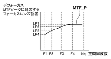
このように、図10(b)で示した空間周波数ごとのデフォーカスMTF情報を、S301、S302で算出した撮影画像やAFの評価帯域の重みづけに基づいて加算し、撮影画像のデフォーカスMTF(C1)とAFのデフォーカスMTF(C2)を得る。図10(c)に、得られた2つのデフォーカスMTFであるC1,C2を示している。横軸はフォーカスレンズ104の位置で、縦軸は、空間周波数毎に重み付け加算されたMTFの値となっている。カメラMPU125は、各々のMTF曲線の極大値位置を検出する。曲線C1の極大値と対応するフォーカスレンズ104の位置としてP_img(第1の結像位置)が検出される。曲線C2の極大値と対応するフォーカスレンズ104の位置としてP_AF(第2の結像位置)が検出される。
In this way, the defocus MTF information for each spatial frequency shown in FIG. 10B is added based on the captured image calculated in S301 and S302 and the weight of the AF evaluation band, and the defocus MTF of the captured image is added. (C1) and AF defocus MTF (C2) are obtained. FIG. 10 (c) shows two obtained defocus MTFs C1 and C2. The horizontal axis represents the position of the
S303でカメラMPU125は、空間周波数BP補正値(BP3)を以下の式(9)により算出する。
BP3=P_AF−P_img (9)
式(9)により、撮影画像の合焦位置とAFで検出される合焦位置の間で発生しうる誤差を補正するための補正値を補正することができる。
In S303, the
BP3 = P_AF−P_img (9)
According to Expression (9), it is possible to correct a correction value for correcting an error that may occur between the focus position of the captured image and the focus position detected by AF.
上述したように撮影画像の合焦位置は、被写体、撮影光学系、および光学ローパスフィルタのそれぞれの空間周波数特性、信号生成時の空間周波数特性、鑑賞時の周波数ごとの感度を示す空間周波数特性や、撮影画像に施される画像処理などによって変化する。本実施形態では、撮影画像の生成過程に遡って空間周波数特性を算出することにより、高精度に撮影画像の合焦位置を算出することができる。例えば、撮影画像の記録サイズや、画像処理で行われる超解像処理、シャープネスなどによって、撮影画像の合焦位置を変更する。また、撮影画像の記録後に、どの程度の画像サイズや拡大率で鑑賞されるかや鑑賞する際の鑑賞距離などは、鑑賞者の評価帯域に影響を与える。そして、画像サイズが大きくなるほど、また、鑑賞距離が短くなるほど、鑑賞者の評価帯域を高周波成分に重きを置いた特性とすることで、撮影画像の合焦位置も変更される。 As described above, the in-focus position of the captured image is determined by the spatial frequency characteristics of the subject, the imaging optical system, and the optical low-pass filter, the spatial frequency characteristics at the time of signal generation, and the spatial frequency characteristics indicating the sensitivity for each frequency during viewing. It varies depending on the image processing applied to the photographed image. In the present embodiment, the in-focus position of the photographed image can be calculated with high accuracy by calculating the spatial frequency characteristics going back to the process of generating the photographed image. For example, the in-focus position of the photographed image is changed by the recording size of the photographed image, super-resolution processing performed by image processing, sharpness, or the like. In addition, after recording a photographed image, the degree of image size and the magnification rate at which the image is viewed, the viewing distance for viewing, and the like affect the evaluation band of the viewer. As the image size becomes larger and the viewing distance becomes shorter, the focus position of the photographed image is also changed by setting the appreciator's evaluation band to emphasize the high frequency component.
一方で、AFが検出する合焦位置も同様に、被写体、撮影光学系、および光学ローパスフィルタそれぞれの空間周波数特性、信号生成時の空間周波数特性、AF評価に用いるデジタルフィルタ空間周波数特性などにより変化する。本実施形態では、AFに用いられる信号が生成される過程に遡って空間周波数特性を算出することにより、高精度にAFが検出する合焦位置を算出することができる。例えば、第1の読み出しモードでAFを行う際にも柔軟に対応できる。その場合には、信号生成時の空間周波数特性を、第1の読み出しモードに対応した特性に変更して、重みづけ係数を算出すればよい。 On the other hand, the in-focus position detected by AF also varies depending on the spatial frequency characteristics of the subject, the imaging optical system, and the optical low-pass filter, the spatial frequency characteristics at the time of signal generation, the digital filter spatial frequency characteristics used for AF evaluation, etc. To do. In the present embodiment, the in-focus position detected by the AF can be calculated with high accuracy by calculating the spatial frequency characteristics going back to the process of generating the signal used for the AF. For example, it is possible to flexibly cope with AF in the first reading mode. In that case, the weighting coefficient may be calculated by changing the spatial frequency characteristic at the time of signal generation to a characteristic corresponding to the first readout mode.
また、本実施形態で説明した撮像装置は、レンズ交換式一眼レフカメラであるため、レンズユニット100の交換が可能である。レンズユニット100が交換された場合、レンズMPU117は各空間周波数に対応したデフォーカスMTF情報を、カメラ本体120に送信する。そして、カメラMPU125が、撮影画像の合焦位置やAFが検出する合焦位置を算出するので、交換レンズ毎に高精度な補正値の算出を行うことができる。レンズユニット100は、デフォーカスMTF情報だけでなく、撮影光学系の空間周波数特性などの情報もカメラ本体120に送信してもよい。その情報の活用方法は、上述のとおりである。
In addition, since the imaging apparatus described in this embodiment is a lens interchangeable single-lens reflex camera, the
また、同様に、カメラ本体120を交換した場合には、画素ピッチや光学ローパスフィルタの特性などが変わる場合がある。上述の通り、そのような場合でも、カメラ本体120の特性に合わせた補正値が算出されるため、高精度に補正を行うことができる。
Similarly, when the
上述の説明では、補正値の計算をカメラMPU125で行ったが、レンズMPU117で行ってもよい。その場合には、カメラMPU125から、レンズMPU117に対して、図11を用いて説明した各種情報を送信し、レンズMPU117がデフォーカスMTF情報などを用いて補正値を算出してもよい。この場合、図1のS24で、カメラMPU125から送信された合焦位置に対して、レンズMPU117が補正を施して、レンズ駆動を行えばよい。
In the above description, the correction value is calculated by the
本実施形態では、焦点検出に用いる信号の特性(縦横、色、空間周波数帯域)に着目して、AF用の補正値を算出している。そのため、AFの方式によらず、同様の方法で、補正値の算出を行うことができる。AF方式毎に、補正方法、補正に用いるデータを有する必要がないため、データの記憶容量、演算負荷の低減を行うことができる。 In the present embodiment, the correction value for AF is calculated by paying attention to the characteristics (vertical and horizontal, color, spatial frequency band) of the signal used for focus detection. Therefore, the correction value can be calculated by the same method regardless of the AF method. Since it is not necessary to have a correction method and data used for correction for each AF method, it is possible to reduce data storage capacity and calculation load.
●(第2の実施形態)
次に、本発明の第2の実施形態について説明する。第1の実施形態との主な違いは、空間周波数BP補正値の算出方法が異なる点である。第1の実施形態では、撮影光学系の空間周波数ごとの特性を表す値としてデフォーカスMTF情報を用いた。しかしながら、デフォーカスMTF情報は、データ量が多く、記憶容量、演算負荷が大きくなるため、第2の実施形態では、デフォーカスMTFの極大値情報を用いて空間周波数BP補正値を算出する。これにより、レンズメモリ118もしくはRAM125bの容量を節約し、レンズ−カメラ間の通信容量の低減、カメラMPU125で行う演算負荷の低減などが実現できる。
● (Second Embodiment)
Next, a second embodiment of the present invention will be described. The main difference from the first embodiment is that the calculation method of the spatial frequency BP correction value is different. In the first embodiment, the defocus MTF information is used as a value representing the characteristic for each spatial frequency of the photographing optical system. However, since the defocus MTF information has a large amount of data, a large storage capacity, and a large calculation load, in the second embodiment, the spatial frequency BP correction value is calculated using the maximum value information of the defocus MTF. Thereby, it is possible to save the capacity of the lens memory 118 or the
なお、撮像装置のブロック図(図2)、各焦点検出方式の説明図(図3(a)から5)、焦点検出領域の説明図(図6)、焦点検出処理および各種BP補正値算出処理のフローチャート(図1、図7、図9(a))は、本実施形態においても流用する。また、空間周波数BP補正値算出処理のフローチャート(図10(a))および各評価帯域の説明図(図11)についても流用する。 It should be noted that the block diagram of the imaging apparatus (FIG. 2), the explanatory diagrams of the respective focus detection methods (FIGS. 3A to 5), the explanatory diagram of the focus detection area (FIG. 6), the focus detection process, and various BP correction value calculation processes The flowcharts (FIGS. 1, 7, and 9A) are also used in this embodiment. The flowchart of the spatial frequency BP correction value calculation process (FIG. 10A) and the explanatory diagram of each evaluation band (FIG. 11) are also used.
本実施形態における空間周波数BP補正値(BP3)の算出方法を、図12を用いて説明する。
S300でカメラMPU125は空間周波数BP補正情報を取得する。
A method of calculating the spatial frequency BP correction value (BP3) in the present embodiment will be described with reference to FIG.
In step S300, the
図12は、撮影光学系の特性である空間周波数ごとのデフォーカスMTFの極大値を示すフォーカスレンズ104位置を示している。図10(b)に示した離散的な空間周波数F1からF4について、デフォーカスMTFがピーク(極大値)となるフォーカスレンズ位置LP4、LP5、LP6、LP7が縦軸に示されている。本実施形態では、このLP4〜LP7を、MTF_P(n)(1≦n≦4)としてレンズメモリ118またはRAM125bに記憶する。記憶されている情報が、焦点検出領域の位置、ズーム位置やフォーカスレンズ位置に対応していることは、第1の実施形態と同様である。
FIG. 12 shows the position of the
第2の実施形態では、図10(a)に示した空間周波数BP補正値処理のS300で、カメラMPU125は、補正対象となっている焦点検出結果に応じたズーム位置、フォーカスレンズ位置に対応した補正値を取得する。
S301、S302でカメラMPU125は、第1の実施形態と同様の処理を行う。
In the second embodiment, in S300 of the spatial frequency BP correction value processing shown in FIG. 10A, the
In S301 and S302, the
S303でカメラMPU125は、空間周波数BP補正値(BP3)を算出する。空間周波数BP補正値の算出を行うに際し、カメラMPU125はまず、撮影画像の合焦位置(P_img)とAFが検出する合焦位置(P_AF)を、以下の式(10)および(11)に従って算出する。算出には、S300で得たデフォーカスMTF情報MTF_P(n)と、S301、S302で得た評価帯域W1,W2を用いる。
P_img=MTF_P(1)×W1(1)+MTF_P(2)×W1(2)+MTF_P(3)×W1(3)+MTF_P(4)×W1(4) (10)
P_AF=MTF_P(1)×W2(1)+MTF_P(2)×W2(2)+MTF_P(3)×W2(3)+MTF_P(4)×W2(4) (11)
In S303, the
P_img = MTF_P (1) × W1 (1) + MTF_P (2) × W1 (2) + MTF_P (3) × W1 (3) + MTF_P (4) × W1 (4) (10)
P_AF = MTF_P (1) × W2 (1) + MTF_P (2) × W2 (2) + MTF_P (3) × W2 (3) + MTF_P (4) × W2 (4) (11)
つまり、図12で示した空間周波数ごとのデフォーカスMTFの極大値情報MTF_P(n)を、S301、S302で算出した撮影画像やAFの評価帯域W1,W2で重みづけ加算する。それにより、撮影画像の合焦位置(P_img)とAFが検出する合焦位置(P_AF)を算出している。 That is, the maximum value information MTF_P (n) of the defocus MTF for each spatial frequency shown in FIG. 12 is weighted and added with the captured image calculated in S301 and S302 and the AF evaluation bands W1 and W2. Thereby, the focus position (P_img) of the captured image and the focus position (P_AF) detected by the AF are calculated.
次にカメラMPU125は、空間周波数BP補正値(BP3)を、第1の実施形態と同様に、以下の式(9)により算出する。
BP3=P_AF−P_img (9)
Next, the
BP3 = P_AF−P_img (9)
本実施形態では、空間周波数BP補正値をより簡便に算出することができる。本実施形態では、空間周波数BP補正値の精度は第1の実施形態より若干劣るが、空間周波数BP補正値を算出するために記憶しておく情報量の削減、レンズ−カメラ間の通信量の削減、カメラMPU125で行う演算負荷の低減が実現できる。
In the present embodiment, the spatial frequency BP correction value can be calculated more easily. In this embodiment, the accuracy of the spatial frequency BP correction value is slightly inferior to that of the first embodiment, but the amount of information stored for calculating the spatial frequency BP correction value is reduced, and the communication amount between the lens and the camera is reduced. Reduction of calculation load performed by the
●(第3の実施形態)
次に、本発明の第3の実施形態について説明する。本実施形態も空間周波数BP補正値の算出方法が上述の実施形態と異なる。本実施形態では、空間周波数BP補正値を算出する必要性がない場合には算出しないことにより、空間周波数BP補正値の精度を低下させずに、レンズ−カメラ間の通信容量の低減やカメラMPU125で行う演算負荷を低減する。
● (Third embodiment)
Next, a third embodiment of the present invention will be described. This embodiment is also different from the above-described embodiment in the method of calculating the spatial frequency BP correction value. In this embodiment, the calculation is not performed when there is no need to calculate the spatial frequency BP correction value, thereby reducing the communication capacity between the lens and the camera and the
なお、撮像装置のブロック図(図2)、各焦点検出方式の説明図(図3(a)から6)、焦点検出領域の説明図(図6)、焦点検出処理および各種BP補正値算出処理のフローチャート(図1、図7、図9(a))は、本実施形態においても流用する。また、空間周波数BP補正値算出処理に関する図(図10(b)〜図10(c))についても流用する。 It should be noted that the block diagram of the imaging device (FIG. 2), the explanatory diagrams of the respective focus detection methods (FIGS. 3A to 6), the explanatory diagram of the focus detection area (FIG. 6), the focus detection process, and various BP correction value calculation processes The flowcharts (FIGS. 1, 7, and 9A) are also used in this embodiment. In addition, the diagrams related to the spatial frequency BP correction value calculation processing (FIGS. 10B to 10C) are also used.
本実施形態における空間周波数BP補正値(BP3)の算出方法を、図13のフローチャートを用いて説明する。図13において、図10(a)と同様の処理は同じ参照数字を付して重複する説明を省略する。 A method for calculating the spatial frequency BP correction value (BP3) in the present embodiment will be described with reference to the flowchart of FIG. In FIG. 13, the same processes as those in FIG. 10A are denoted by the same reference numerals, and redundant description is omitted.
S3000でカメラMPU125は、空間周波数BP補正値を算出する必要があるか否かを判定する。第1の実施形態で説明したことからわかる通り、撮影画像の評価帯域W1とAF評価帯域W2が似ているほど、空間周波数BP補正値は小さくなる。そのため、本実施形態では、2つの評価帯域の差が空間周波数BP補正値を算出する必要がない程度に小さいと判定される場合には、補正値の算出を省略する。
In S3000, the
具体的には、2つの評価帯域の差が十分小さくなる条件を満たす場合に、補正値の算出を省略する。例えば、AFに用いる信号も第1の読み出しモードで読み出された信号である場合には、撮影画像の評価帯域とAF評価帯域は等しくなる。さらに、撮影画像を鑑賞する際の空間周波数ごとの感度を示す空間周波数特性と類似の空間周波数特性のデジタルフィルタをAF評価信号の処理時に用いる場合には、鑑賞時の空間周波数特性とデジタルフィルタの空間周波数特性が等しくなる。このような状況は、表示器126に表示する画像を拡大して表示する場合などに発生する。
また、同様に、撮影画像が第2の読み出しモードで読み出された信号で生成される場合にも撮影画像の評価帯域とAF評価帯域が等しくなることが想定される。このような状況は、撮影画像の記録画像サイズを小さく設定している場合などに、発生する。
Specifically, the calculation of the correction value is omitted when the condition that the difference between the two evaluation bands is sufficiently small is satisfied. For example, when the signal used for AF is also a signal read in the first reading mode, the evaluation band of the captured image is equal to the AF evaluation band. Furthermore, when a digital filter having a spatial frequency characteristic similar to the spatial frequency characteristic indicating the sensitivity for each spatial frequency when viewing a captured image is used when processing the AF evaluation signal, the spatial frequency characteristic during viewing and the digital filter Spatial frequency characteristics are equal. Such a situation occurs when an image to be displayed on the
Similarly, when the captured image is generated with a signal read in the second readout mode, it is assumed that the evaluation band of the captured image is equal to the AF evaluation band. Such a situation occurs when the recording image size of the captured image is set small.
S3000でカメラMPU125は、このような、予め定められた条件のいずれかが満たされる場合に、補正値の算出が不要と判定し、処理をS3001に進める。
S3001でカメラMPU125は、補正値の算出を行わないため、BP3に0を代入し、空間周波数BP補正値(BP3)の算出処理を終了する。
In S3000, the
In step S3001, since the
一方、S3000で、補正値の算出が必要であると判定された場合、カメラMPU125は、S300〜S303を第1の実施形態(または第2の実施形態)と同様に実施する。
On the other hand, when it is determined in S3000 that the correction value needs to be calculated, the
このように、本実施形態では、空間周波数BP補正値の算出が不要と判定された場合には補正値の算出を省略するので、補正値の算出用に記憶しておくデータ量は削減できないが、補正値算出時のデータ通信量や演算負荷を低減することができる。なお、第2の実施形態と組み合わせることも可能であり、その場合は補正値の算出用に記憶しておくデータ量の削減はもちろん、補正値算出時のデータ通信量や演算負荷を一層低減することができる。 As described above, in this embodiment, when it is determined that the calculation of the spatial frequency BP correction value is unnecessary, the calculation of the correction value is omitted, so that the amount of data stored for calculating the correction value cannot be reduced. Thus, it is possible to reduce the amount of data communication and the calculation load when calculating the correction value. It is also possible to combine with the second embodiment. In this case, not only the amount of data stored for calculating the correction value but also the data communication amount and calculation load when calculating the correction value are further reduced. be able to.
本実施形態では、空間周波数BP補正値の省略について説明したが、縦横BP補正値や色BP補正値についても不要と判定できれば省略することができる。例えば、焦点検出を垂直方向、水平方向の両方のコントラストを考慮して行う場合は、縦横BP補正値の算出を省略してもよい。また、撮影画像に用いる色信号と、焦点検出に用いる色信号が等しい場合は、色BP補正値の算出を省略してもよい。 In this embodiment, the omission of the spatial frequency BP correction value has been described. However, the vertical / horizontal BP correction value and the color BP correction value can also be omitted if it can be determined that they are unnecessary. For example, when focus detection is performed in consideration of both vertical and horizontal contrasts, calculation of the vertical and horizontal BP correction values may be omitted. If the color signal used for the captured image is the same as the color signal used for focus detection, the calculation of the color BP correction value may be omitted.
●(第4の実施形態)
次に、本発明の第4の実施形態について説明する。第1の実施形態とは、各種BP補正値の算出方法が主に異なる。第1の実施形態では、縦横BP補正値、色BP補正値、空間周波数BP補正値を、各々異なる補正値として算出した。しかしながら、縦横BP補正値や色BP補正値も空間周波数に依存するため、第4の実施形態では、縦横BP補正値および色BP補正値についても空間周波数を考慮して算出する。これにより、レンズメモリ118もしくはRAM125bに必要な容量は増えるが、より高精度に補正値を算出することができる。また、BP補正値の算出における演算の順序や一時記憶する係数の情報などを変更することにより、演算量の低減を図ることができる。
● (Fourth embodiment)
Next, a fourth embodiment of the present invention will be described. It differs from the first embodiment mainly in the method for calculating various BP correction values. In the first embodiment, the vertical / horizontal BP correction value, the color BP correction value, and the spatial frequency BP correction value are calculated as different correction values. However, since the vertical / horizontal BP correction value and the color BP correction value also depend on the spatial frequency, in the fourth embodiment, the vertical / horizontal BP correction value and the color BP correction value are also calculated in consideration of the spatial frequency. As a result, the required capacity of the lens memory 118 or the
なお、撮像装置のブロック図(図2)、各焦点検出方式の説明図(図3(a)から図5)、焦点検出領域の説明図(図6)、各評価帯域の説明図(図11)は、本実施形態においても共通であるため、以下の説明で流用する。 The block diagram of the imaging device (FIG. 2), the explanatory diagrams of each focus detection method (FIGS. 3A to 5), the explanatory diagram of the focus detection area (FIG. 6), and the explanatory diagrams of each evaluation band (FIG. 11). ) Is common to the present embodiment, and is used in the following description.
本実施形態におけるBP補正値(BP)の算出方法を、図14から図17を用いて説明する。
図14において、第1の実施形態における焦点検出処理と同様の処理を行うものについては、図1Aと同じ参照数字を付している。図14では、図1AにおけるS20からS22がS400に、S23の処理がS401に、それぞれ置き換えられている点が異なる。S400でカメラMPU125は、方向(縦横)、色、空間周波数など、各種の誤差要因をまとめて補正するためのBP補正値(BP)を算出する。
A method of calculating the BP correction value (BP) in the present embodiment will be described with reference to FIGS.
In FIG. 14, the same reference numerals as those in FIG. 1A are given to those performing the same process as the focus detection process in the first embodiment. 14 differs from FIG. 1A in that S20 to S22 are replaced with S400, and the process of S23 is replaced with S401. In S400, the
S401でカメラMPU125は、算出されたBP補正値(BP)を用いて以下の式(12)により焦点検出結果DEF_Bを補正し、補正後の焦点検出結果DEF_Aを算出する。
DEF_A=DEF_B+BP (12)
In step S401, the
DEF_A = DEF_B + BP (12)
本実施形態では、R(赤)、G(緑)、およびB(青)の3色と、縦(垂直)および横(水平)の2方向とを組み合わせた6種の空間周波数の各々のデフォーカスMTFの極大値を示すフォーカスレンズ104位置の情報を用いてBP補正値を算出する。これにより、色や方向(縦横)についても、空間周波数の依存性を考慮することができ、より高精度なBP補正値を算出することができ、補正精度を向上することができる。
In the present embodiment, each of the six spatial frequency combinations of the three colors R (red), G (green), and B (blue) and two directions of vertical (vertical) and horizontal (horizontal) is combined. A BP correction value is calculated using information on the position of the
図15は、図14のS400におけるBP補正値算出処理の詳細を示すフローチャートである。
S500で、カメラMPU125は、BP補正値の算出に必要なパラメータ(算出条件)を取得する。BP補正値は、第1の実施形態で説明したように、フォーカスレンズ104の位置、ズーム状態を示す第1レンズ群101の位置、焦点検出領域の位置など、撮影光学系の変化や焦点検出光学系の変化に伴い変化する。そのため、カメラMPU125は、S500で例えばフォーカスレンズ104の位置、ズーム状態を示す第1レンズ群101の位置、および、焦点検出領域の位置の情報を取得する。さらに、カメラMPU125はS500において、焦点検出に用いる信号と撮影画像に用いる信号の色や評価方向に関する設定情報を取得する。
FIG. 15 is a flowchart showing details of the BP correction value calculation processing in S400 of FIG.
In S500, the
図16(a)に、色や評価方向に関する設定情報の例を示す。この設定情報は、焦点状態を評価するコントラストの方向(水平、垂直)と色(赤、緑、青)の各組み合わせに対する、重み付けの大きさを示す情報である。設定情報は、焦点検出用と撮影画像用とで、異なる情報を有する。例えば、水平方向で緑色の信号を用いたコントラストAFの結果を補正する場合、焦点検出用の設定情報を、
K_AF_RH=0
K_AF_GH=1
K_AF_BH=0
K_AF_RV=0
K_AF_GV=0
K_AF_BV=0
のように定めればよい。このような設定情報により、焦点検出用の信号のデフォーカスMTFのピーク情報は、水平方向で緑色の信号の特性と同じであることを示すことができる。
FIG. 16A shows an example of setting information related to color and evaluation direction. This setting information is information indicating the weighting level for each combination of contrast direction (horizontal and vertical) and color (red, green and blue) for evaluating the focus state. The setting information has different information for the focus detection and the captured image. For example, when correcting the result of contrast AF using a green signal in the horizontal direction, setting information for focus detection is
K_AF_RH = 0
K_AF_GH = 1
K_AF_BH = 0
K_AF_RV = 0
K_AF_GV = 0
K_AF_BV = 0
It may be determined as follows. With such setting information, it can be shown that the defocus MTF peak information of the focus detection signal is the same as the characteristics of the green signal in the horizontal direction.
一方、撮影画像用の設定情報は、
K_IMG_RH=0.15
K_IMG_GH=0.29
K_IMG_BH=0.06
K_IMG_RV=0.15
K_IMG_GV=0.29
K_IMG_BV=0.06
のように定めればよい。これは、RGBの信号をY信号相当に変換するための重み付けを行い、撮影画像はY信号で評価し、水平方向、垂直方向いずれのコントラストも同等に評価することを想定して設定される値である。ただし、設定値や設定値の種類などは、これに限らない。
On the other hand, the setting information for captured images is
K_IMG_RH = 0.15
K_IMG_GH = 0.29
K_IMG_BH = 0.06
K_IMG_RV = 0.15
K_IMG_GV = 0.29
K_IMG_BV = 0.06
It may be determined as follows. This is a value that is set on the assumption that weighting is performed to convert RGB signals into Y signals, the captured images are evaluated with Y signals, and the contrast in both the horizontal and vertical directions is evaluated equally. It is. However, the setting value and the type of the setting value are not limited to this.
S501でカメラMPU125は、後述するピーク係数に変更があるか否かを判定する。この判定は、事前に行われたBP補正値の算出と今回のBP補正値の算出における各種条件が同一の場合、ピーク係数の再算出を省略するために行っている。本実施形態でカメラMPU125は、焦点検出用と撮影画像用の色や評価方向に関する設定情報(図16(a))と焦点検出領域の位置に変更がなければ、ピーク係数に変更なしと判定し、S502からS504をスキップして処理をS505に移行させる。
In step S501, the
S501で、初めてピーク係数を算出する場合もしくはピーク係数の変更ありと判定された場合、カメラMPU125は処理をS502に進め、BP補正情報を取得する。BP補正情報は、被写体の空間周波数ごとの撮影光学系の結像位置に関する情報である。上述した3色と2方向との6通りの組み合わせの各々について、空間周波数fと撮像素子上の焦点検出領域の位置(x,y)を変数とした以下の式(13)で表現される。
MTF_P_RH(f,x,y)=(rh(0)×x+rh(1)×y+rh(2))×f2+(rh(3)×x+rh(4)×y+rh(5))×f+(rh(6)×x+rh(7)×y+rh(8)) (13)
In S501, when calculating the peak coefficient for the first time or when it is determined that the peak coefficient has been changed, the
MTF_P_RH (f, x, y) = (rh (0) × x + rh (1) × y + rh (2)) × f2 + (rh (3) × x + rh (4) × y + rh (5)) × f + (rh (6)) × x + rh (7) × y + rh (8)) (13)
なお、式(13)は、赤(R)色の信号について水平(H)方向に対応した空間周波数ごとのデフォーカスMTFの極大値を示すフォーカスレンズ104位置の情報MTF_P_RHの式を示しているが、他の組み合わせについても同様の式で表される。また、本実施形態において、rh(n)(0≦n≦8)は、レンズユニット100のレンズメモリ118にあらかじめ記憶され、カメラMPU125は、レンズMPU117に要求してrh(n)(0≦n≦8)を取得するものとする。しかし、rh(n)(0≦n≦8)はカメラRAM125bの不揮発性領域に記憶されていてもよい。
The expression (13) shows the expression of the information MTF_P_RH of the
赤と垂直(MTF_P_RV)、緑と水平(MTF_P_GH)、緑と垂直(MTF_P_GV)、青と水平(MTF_P_BH)、青と垂直(MTF_P_BV)の各組み合わせにおける係数(rv,gh,gv,bh,bv)も同様に記憶並びに取得できる。 Coefficients (rv, gh, gv, bh, bv) in each combination of red and vertical (MTF_P_RV), green and horizontal (MTF_P_GH), green and vertical (MTF_P_GV), blue and horizontal (MTF_P_BH), blue and vertical (MTF_P_BV) Can be stored and retrieved in the same manner.
次に、S503でカメラMPU125は、得られたBP補正情報に対して、焦点検出領域の位置や評価信号の色、コントラスト方向に関する重み付けを行う。まずカメラMPU125は、BP補正値を算出する際の焦点検出領域の位置についての情報を用いて、BP補正情報を計算する。
具体的には、式(13)のx,yに焦点検出領域の位置情報を代入する。この計算により式(13)は、以下の式(14)のような形式で表される。
MTF_P_RH(f)=Arh×f2+Brh×f+Crh (14)
カメラMPU125は、MTF_P_RV(f)、MTF_P_GH(f)、MTF_P_GV(f)、MTF_P_BH(f)、MTF_P_BV(f)についても同様に計算する。これらは、デフォーカスMTF中間情報に相当する。
In step S <b> 503, the
Specifically, the position information of the focus detection area is substituted into x and y in Expression (13). By this calculation, the expression (13) is expressed in the form of the following expression (14).
MTF_P_RH (f) = Arh × f2 + Brh × f + Crh (14)
The
図16(b)は、S503で焦点検出領域の位置情報を代入した後のBP補正情報の例を示し、横軸は空間周波数を、縦軸はデフォーカスMTFの極大値を示すフォーカスレンズ104の位置(ピーク位置)である。図示の通り、色収差が大きい場合には、色ごとの曲線が乖離し、縦横差が大きい場合には、図中の水平方向と垂直方向の曲線が乖離する。このように、本実施形態では、色(RGB)と評価方向(HとV)との組み合わせごとに、空間周波数に対応したデフォーカスMTF情報を有する。これにより、高精度なBP補正値算出を可能とする。 FIG. 16B shows an example of BP correction information after the position information of the focus detection area is substituted in S503. The horizontal axis indicates the spatial frequency, and the vertical axis indicates the maximum value of the defocus MTF. Position (peak position). As shown in the figure, when the chromatic aberration is large, the curves for each color are deviated, and when the vertical and horizontal differences are large, the horizontal and vertical curves in the figure are deviated. Thus, in this embodiment, defocus MTF information corresponding to the spatial frequency is provided for each combination of color (RGB) and evaluation direction (H and V). Thereby, highly accurate BP correction value calculation is enabled.
次に、カメラMPU125は、S500で取得している設定情報を構成する12個の係数(図16(a))を、BP補正情報を用いて重み付けする。これにより、設定情報が、焦点検出、撮像で評価する色、方向に関して重み付けされる。具体的には、カメラMPU125は、焦点検出用の空間周波数特性MTF_P_AF(f)と撮影画像用の空間周波数特性MTF_P_IMG(f)を、式(15)および(16)を用いて算出する。
MTF_P_AF(f)=
K_AF_RH×MTF_P_RH(f)
+K_AF_RV×MTF_P_RV(f)
+K_AF_GH×MTF_P_GH(f)
+K_AF_GV×MTF_P_GV(f)
+K_AF_BH×MTF_P_BH(f)
+K_AF_BV×MTF_P_BV(f) (15)
MTF_P_IMG(f)=
K_IMG_RH×MTF_P_RH(f)
+K_IMG_RV×MTF_P_RV(f)
+K_IMG_GH×MTF_P_GH(f)
+K_IMG_GV×MTF_P_GV(f)
+K_IMG_BH×MTF_P_BH(f)
+K_IMG_BV×MTF_P_BV(f) (16)
Next, the
MTF_P_AF (f) =
K_AF_RH × MTF_P_RH (f)
+ K_AF_RV × MTF_P_RV (f)
+ K_AF_GH × MTF_P_GH (f)
+ K_AF_GV × MTF_P_GV (f)
+ K_AF_BH × MTF_P_BH (f)
+ K_AF_BV × MTF_P_BV (f) (15)
MTF_P_IMG (f) =
K_IMG_RH × MTF_P_RH (f)
+ K_IMG_RV × MTF_P_RV (f)
+ K_IMG_GH × MTF_P_GH (f)
+ K_IMG_GV × MTF_P_GV (f)
+ K_IMG_BH × MTF_P_BH (f)
+ K_IMG_BV × MTF_P_BV (f) (16)
図16(c)に、MTF_P_AF(f)とMTF_P_IMG(f)の例を、図16(b)と同様の様式で示す。本実施形態では、このように、焦点検出領域の位置や評価する色や方向についての変数の計算を、空間周波数の変数に関する計算に先駆けて行う。計算の結果、MTF_P_AF(f)とMTF_P_IMG(f)は、以下の式(17)および(18)の形式で表される。
MTF_P_AF(f)=Aaf×f2+Baf×f+Caf (17)
MTF_P_IMG(f)=Aimg×f2+Bimg×f+Cimg (18)
FIG. 16C shows an example of MTF_P_AF (f) and MTF_P_IMG (f) in the same manner as FIG. 16B. In this embodiment, in this way, the calculation of the variables for the position of the focus detection region, the color and direction to be evaluated is performed prior to the calculation for the spatial frequency variable. As a result of the calculation, MTF_P_AF (f) and MTF_P_IMG (f) are expressed in the following formulas (17) and (18).
MTF_P_AF (f) = Aaf × f2 + Baf × f + Caf (17)
MTF_P_IMG (f) = Aimg × f2 + Bimg × f + Cimg (18)
図16(c)には、離散的な空間周波数F1からF4について、式(17)に代入して得られるデフォーカスMTFがピーク(極大値)となるフォーカスレンズ位置(ピーク位置)LP4_AF、LP5_AF、LP6_AF、LP7_AFが縦軸に示されている。 FIG. 16C shows focus lens positions (peak positions) LP4_AF, LP5_AF at which the defocus MTF obtained by substituting into the equation (17) for the discrete spatial frequencies F1 to F4 reaches a peak (maximum value). LP6_AF and LP7_AF are shown on the vertical axis.
S504でカメラMPU125は、このLP4_AF〜LP7_AFを、ピーク係数MTF_P_AF(n)(1≦n≦4)としてレンズメモリ118またはRAM125bに記憶する。カメラMPU125はまた、LP4_Img〜LP7_Imgを、ピーク係数MTF_P_Img(n)(1≦n≦4)としてレンズメモリ118またはRAM125bに記憶し、処理をS505に進める。
In S504, the
次に、S505でカメラMPU125は、焦点検出用もしくは撮影画像用の信号の評価帯域に変更があるか否かを判定し、評価帯域に変更がない場合には処理をS507に進め、BP補正値を算出する。BP補正値を算出するに際し、カメラMPU125はまず、撮影画像の合焦位置(P_img)とAFが検出する合焦位置(P_AF)を、第2の実施形態と同様に、以下の式(19)および(20)に従って算出する。算出には、第1の実施形態のS301,S302で得た評価帯域W1,W2を用いる。
Next, in S505, the
P_img=MTF_P_Img(1)×W1(1)+MTF_P_Img(2)×W1(2)+MTF_P_Img(3)×W1(3)+MTF_P_Img(4)×W1(4) (19)
P_AF=MTF_P_AF(1)×W2(1)+MTF_P_AF(2)×W2(2)+MTF_P_AF(3)×W2(3)+MTF_P_AF(4)×W2(4) (20)
P_img = MTF_P_Img (1) × W1 (1) + MTF_P_Img (2) × W1 (2) + MTF_P_Img (3) × W1 (3) + MTF_P_Img (4) × W1 (4) (19)
P_AF = MTF_P_AF (1) × W2 (1) + MTF_P_AF (2) × W2 (2) + MTF_P_AF (3) × W2 (3) + MTF_P_AF (4) × W2 (4) (20)
つまり、カメラMPU125は、図16(c)で示した空間周波数ごとのデフォーカスMTFの極大値情報を、第1の実施形態のS301、S302で算出した撮影画像やAFの評価帯域W1,W2で重みづけ加算する。それにより、撮影画像の合焦位置(P_img)とAFが検出する合焦位置(P_AF)を算出している。
That is, the
次にカメラMPU125は、BP補正値(BP)を、第1の実施形態と同様に、以下の式(21)により算出する。
BP=P_AF−P_img (21)
Next, the
BP = P_AF−P_img (21)
一方、S505で評価帯域に変更があると判定された場合、カメラMPU125は処理をS506に進め、評価帯域情報を取得する。評価帯域情報は、第1の実施形態の撮影画像の評価帯域W1やAF評価帯域W2に相当するもので、焦点検出や撮影画像の設定や状況に応じて、図11で説明した考え方に則って算出することができる。S506で、評価帯域情報の取得を終えると、カメラMPU125はS507に処理を進めて上述の通りBP補正値を算出する。
On the other hand, when it is determined in S505 that there is a change in the evaluation band, the
本実施形態では、焦点検出領域の位置、評価信号の色やコントラスト方向に関する処理を、評価帯域に関する処理よりも先行して実行している。これは、撮影者が焦点検出領域の位置を設定により決定している場合、焦点検出領域の位置や、評価する色や方向に関する情報が変更される頻度が低いためである。一方で、信号の評価帯域については、第1の実施形態の図11で説明した通り、撮像素子の読出しモードやAF評価信号のデジタルフィルタなどにより変更される頻度が高い。例えば、信号のS/Nが低下する低照度環境では、デジタルフィルタの帯域をより低帯域に変更することなどが考えられる。本実施形態では、このような場合に、変更の頻度が低い係数(ピーク係数)を算出した後に記憶し、変更の頻度の高い係数(評価帯域)のみを必要に応じて計算し、BP補正値算出を行う。これにより、撮影者が焦点検出領域の位置を設定している場合などには、演算量の低減を行うことができる。 In the present embodiment, the processing related to the position of the focus detection region, the color of the evaluation signal, and the contrast direction is executed prior to the processing related to the evaluation band. This is because when the photographer determines the position of the focus detection area by setting, the frequency of the information on the position of the focus detection area and the color and direction to be evaluated is low. On the other hand, as described with reference to FIG. 11 of the first embodiment, the signal evaluation band is frequently changed by the readout mode of the image sensor or the digital filter of the AF evaluation signal. For example, in a low illuminance environment where the S / N of the signal decreases, it may be possible to change the band of the digital filter to a lower band. In this embodiment, in such a case, a coefficient with a low change frequency (peak coefficient) is calculated and stored, only a coefficient with a high change frequency (evaluation band) is calculated as necessary, and a BP correction value is calculated. Perform the calculation. Thereby, when the photographer has set the position of the focus detection area, the amount of calculation can be reduced.
(変形例)
一方で、複数の焦点検出領域の位置に対応するBP補正値の算出を行う場合も考えられる。例えば、焦点検出時に、複数の焦点検出領域を用いた焦点検出を行う場合や、デフォーカスマップを作成するために、撮影範囲内の複数のデフォーカス量を取得したい場合などが考えらえる。
(Modification)
On the other hand, there may be a case where BP correction values corresponding to the positions of a plurality of focus detection areas are calculated. For example, it is conceivable to perform focus detection using a plurality of focus detection areas at the time of focus detection, or to acquire a plurality of defocus amounts within a shooting range in order to create a defocus map.
このような場合には、評価信号の色、コントラストの方向、評価帯域に関する計算を先行して行い、焦点検出領域の位置に関する計算を、焦点検出領域の位置情報のみを変更しながら行うことにより、演算量を低減することができる。 In such a case, the calculation regarding the color of the evaluation signal, the direction of the contrast, and the evaluation band is performed in advance, and the calculation regarding the position of the focus detection area is performed while changing only the position information of the focus detection area, The amount of calculation can be reduced.
図17は、図14のS400におけるBP補正値算出処理の別の例を示すフローチャートである。図15と同様の処理を行う工程については、同じ参照数字を付し、重複する説明は省略する。 FIG. 17 is a flowchart showing another example of the BP correction value calculation process in S400 of FIG. Steps for performing the same processing as in FIG. 15 are given the same reference numerals, and redundant descriptions are omitted.
S601でカメラMPU125は、後述するBP係数に変更があるか否かを判定する。この判定は、事前に行われたBP補正値の算出と今回のBP補正値の算出における各種条件が同一の場合、BP係数の再算出を省略するために行っている。本実施形態でカメラMPU125は、焦点検出用と撮影画像用の色や評価方向に関する設定情報(図16(a))および評価帯域に関する情報(評価帯域W1,W2)に変更がなければ、BP係数に変更なしと判定し、S605へ処理をスキップする。
In step S601, the
S501で、初めてBP係数を算出する場合もしくはBP係数の変更ありと判定された場合、カメラMPU125は処理をS502に進め、第4の実施形態と同様にBP補正情報を取得して、処理をS603に進める。
S603でカメラMPU125は、式(14)および式(16)を用いて説明したように、6種類のデフォーカスMTFのピーク情報に関して、評価信号の色、コントラスト方向に関する重み付けを行う。ただし、S503と異なり、式(14)への焦点検出領域の位置情報の代入は行わない。従って、MTF_P_RH(f,x,y)、MTF_P_RV(f,x,y)、MTF_P_GH(f,x,y)、MTF_P_GV(f,x,y)、MTF_P_BH(f,x,y)、MTF_P_BV(f,x,y)が得られる。
In S501, when calculating the BP coefficient for the first time or when it is determined that the BP coefficient has been changed, the
In step S <b> 603, the
そして、カメラMPU125は、S500で取得している設定情報を構成する12個の係数(図16(a))を、これらのBP補正情報で重み付けする。具体的には、カメラMPU125は、焦点検出用の空間周波数特性MTF_P_AF(f,x,y)と撮影画像用の空間周波数特性MTF_P_IMG(f,x,y)を、式(22)および(23)を用いて算出する。
MTF_P_AF(f,x,y)=
K_AF_RH×MTF_P_RH(f,x,y)
+K_AF_RV×MTF_P_RV(f,x,y)
+K_AF_GH×MTF_P_GH(f,x,y)
+K_AF_GV×MTF_P_GV(f,x,y)
+K_AF_BH×MTF_P_BH(f,x,y)
+K_AF_BV×MTF_P_BV(f,x,y) (22)
MTF_P_IMG(f,x,y)=
K_IMG_RH×MTF_P_RH(f,x,y)
+K_IMG_RV×MTF_P_RV(f,x,y)
+K_IMG_GH×MTF_P_GH(f,x,y)
+K_IMG_GV×MTF_P_GV(f,x,y)
+K_IMG_BH×MTF_P_BH(f,x,y)
+K_IMG_BV×MTF_P_BV(f,x,y) (23)
Then, the
MTF_P_AF (f, x, y) =
K_AF_RH × MTF_P_RH (f, x, y)
+ K_AF_RV × MTF_P_RV (f, x, y)
+ K_AF_GH × MTF_P_GH (f, x, y)
+ K_AF_GV × MTF_P_GV (f, x, y)
+ K_AF_BH × MTF_P_BH (f, x, y)
+ K_AF_BV × MTF_P_BV (f, x, y) (22)
MTF_P_IMG (f, x, y) =
K_IMG_RH × MTF_P_RH (f, x, y)
+ K_IMG_RV × MTF_P_RV (f, x, y)
+ K_IMG_GH × MTF_P_GH (f, x, y)
+ K_IMG_GV × MTF_P_GV (f, x, y)
+ K_IMG_BH × MTF_P_BH (f, x, y)
+ K_IMG_BV × MTF_P_BV (f, x, y) (23)
さらに、カメラMPU125は、式(19)および(20)と同様に、第1の実施形態のS301,S302で得た評価帯域W1,W2を用いて評価帯域の重み付けを行う。これにより、撮影画像の合焦位置(P_img)と、AFが検出する合焦位置(P_AF)とが、焦点検出領域の位置(x,y)を変数とした関数として、式(24)および(25)のように求まる。
P_img(x,y)=MTF_P_Img(F1,x,y)×W1(1)
+MTF_P_Img(F2,x,y)×W1(2)
+MTF_P_Img(F3,x,y)×W1(3)
+MTF_P_Img(F4,x,y)×W1(4) (24)
P_AF(x,y)=MTF_P_AF(F1,x,y)×W2(1)
+MTF_P_AF(F2,x,y)×W2(2)
+MTF_P_AF(F3,x,y)×W2(3)
+MTF_P_AF(F4,x,y)×W2(4) (25)
Further, the
P_img (x, y) = MTF_P_Img (F1, x, y) × W1 (1)
+ MTF_P_Img (F2, x, y) × W1 (2)
+ MTF_P_Img (F3, x, y) × W1 (3)
+ MTF_P_Img (F4, x, y) × W1 (4) (24)
P_AF (x, y) = MTF_P_AF (F1, x, y) × W2 (1)
+ MTF_P_AF (F2, x, y) × W2 (2)
+ MTF_P_AF (F3, x, y) × W2 (3)
+ MTF_P_AF (F4, x, y) × W2 (4) (25)
S604でカメラMPU125は、式(24)および(25)を構成する係数を、BP係数としてレンズメモリ118またはRAM125bに記憶する。
次に、S605でカメラMPU125は、焦点検出領域の位置に変更があるか否かを判定し、変更がない場合には処理を直接S607に進め、変更がある場合にはS606で焦点検出領域の位置情報を取得してから処理をS607に進める。
In step S604, the
Next, in S605, the
S607でカメラMPU125は、BP補正値の算出を行う焦点検出領域の位置(x1,y1)を式(24)および(25)に代入し、以下の式(26)に従ってBP補正値(BP)を算出する。
BP=P_AF(x1,y1)−P_img(x1,y1) (26)
このように構成することにより、複数の焦点検出領域の位置に対応するBP補正値の算出を行う場合に対応した演算量の低減を行うことができる。
In step S <b> 607, the
BP = P_AF (x1, y1) −P_img (x1, y1) (26)
With this configuration, it is possible to reduce the amount of calculation corresponding to the calculation of BP correction values corresponding to the positions of a plurality of focus detection areas.
また、これらの演算処理の内容は、状態に応じて切り替えてもよい。例えば、焦点検出に用いる焦点検出領域が1つの場合は図15に示したように処理し、複数の場合は図17に示したように処理してもよい。
以上のように構成することにより、色と縦横BPについても空間周波数を考慮して、BP補正値を算出することができ、より高精度な補正を行うことができる。
The contents of these arithmetic processes may be switched according to the state. For example, when there is one focus detection area used for focus detection, processing may be performed as shown in FIG. 15, and when there are a plurality of focus detection regions, processing may be performed as shown in FIG.
By configuring as described above, the BP correction value can be calculated for the color and the vertical and horizontal BP in consideration of the spatial frequency, and more accurate correction can be performed.
●(第5の実施形態)
次に、本発明の第5の実施形態について説明する。第4の実施形態とはBP補正値の算出方法が異なる。第4の実施形態では、撮影光学系から取得するBP補正情報の評価帯域の範囲と、AF評価帯域や撮影画像の評価帯域の範囲とが等しいという前提でBP補正値を算出していた。しかしながら、撮像素子の画素ピッチの微細化に伴い、評価帯域の範囲を高周波帯域側に拡張することが考えられる。また、撮影光学系の高精度化に伴いBP補正情報として有する評価帯域の範囲も高周波帯域側に拡張することが考えられる。
● (Fifth Embodiment)
Next, a fifth embodiment of the present invention will be described. The BP correction value calculation method is different from that of the fourth embodiment. In the fourth embodiment, the BP correction value is calculated on the assumption that the evaluation band range of the BP correction information acquired from the photographing optical system is equal to the AF evaluation band and the evaluation band range of the photographed image. However, it is conceivable that the range of the evaluation band is extended to the high frequency band side as the pixel pitch of the image sensor is reduced. In addition, it is conceivable that the range of the evaluation band possessed as the BP correction information is expanded to the high frequency band side as the photographing optical system becomes more accurate.
本実施形態では、高精度にBP補正値を算出するため、撮像装置と撮影光学系の各々に限界帯域情報を持たせ、各々の大小関係に応じて、補正値算出処理を切り替える。限界帯域情報を用いて評価帯域の調整を行うことにより、新旧の撮像装置や撮影光学系の組み合わせによらず、高精度にBP補正値を算出することができる。 In the present embodiment, in order to calculate the BP correction value with high accuracy, each of the imaging device and the photographing optical system is provided with limit band information, and the correction value calculation processing is switched according to the magnitude relationship of each. By adjusting the evaluation band using the limit band information, the BP correction value can be calculated with high accuracy regardless of the combination of old and new imaging devices and photographing optical systems.
なお、撮像装置のブロック図(図2)、各焦点検出方式の説明図(図3(a)から5)、焦点検出領域の説明図(図6)、各評価帯域の説明図(図11)、焦点検出処理(図14)は、本実施形態においても共通であるため、以下の説明で流用する。 In addition, a block diagram of the imaging device (FIG. 2), explanatory diagrams of each focus detection method (FIGS. 3A to 5), an explanatory diagram of the focus detection area (FIG. 6), and an explanatory diagram of each evaluation band (FIG. 11). The focus detection process (FIG. 14) is common to this embodiment, and will be used in the following description.
本実施形態におけるBP補正値(BP)の算出方法を、図18および図19を用いて説明する。
図18において、第4の実施形態における焦点検出処理と同様の処理を行うものについては、図15と同じ参照数字を付している。本実施形態では、BP補正値算出の処理(S507)の前に、限界帯域処理(S700)の工程を有する点で異なる。限界帯域処理では、撮像装置の評価帯域の高周波側の限界値(カメラ限界帯域)と、撮影光学系の評価帯域の高周波側の限界値(レンズ限界帯域)との大小関係を判定する。そして、大小関係に応じて、式(15)および(16)であらわされるMTF_P_AF(f)とMTF_P_IMG(f)の離散化処理を切り替える。
A method of calculating the BP correction value (BP) in the present embodiment will be described with reference to FIGS.
In FIG. 18, the same reference numerals as those in FIG. 15 are attached to those performing the same processing as the focus detection processing in the fourth embodiment. This embodiment is different in that it includes a step of limit band processing (S700) before the BP correction value calculation processing (S507). In the limit band processing, the magnitude relationship between the limit value (camera limit band) on the high frequency side of the evaluation band of the imaging apparatus and the limit value (lens limit band) on the high frequency side of the evaluation band of the photographing optical system is determined. Then, the discretization processing of MTF_P_AF (f) and MTF_P_IMG (f) expressed by the equations (15) and (16) is switched according to the magnitude relationship.
以下、図18のS700で行う限界帯域処理の詳細について、図19(a)を用いて説明する。
S701でカメラMPU125は、限界帯域情報を取得する。ここでカメラMPU125は、カメラ限界帯域情報をROM125aから取得し、レンズ限界帯域情報をレンズメモリ118から取得する。カメラ限界帯域は、主に撮像素子の画素ピッチで定まるナイキスト周波数に基づいて設定される。一方で、レンズ限界帯域には、撮影光学系のMTFの応答が閾値以上となる帯域の限界値や、測定データの信頼性のある帯域の限界値などが設定される。
Hereinafter, the details of the limit band processing performed in S700 of FIG. 18 will be described with reference to FIG.
In step S701, the
次にS702でカメラMPU125は、カメラ限界帯域とレンズ限界帯域の大小を比較する。カメラMPU125は、カメラ限界帯域の方がレンズ限界帯域よりも大きい(限界周波数が高い)場合には処理をS703に進め、カメラ限界帯域がレンズ限界帯域以下の場合には、限界帯域処理を終了する。
In step S <b> 702, the
S703でカメラMPU125は、ピーク係数を加工する。ピーク係数の加工例を、図19(b)を用いて説明する。図19(b)は、第4の実施形態の図16(c)で示したMTF_P_AF(f)とMTF_P_IMG(f)を示している。ここで、レンズ限界帯域はF4、カメラ限界帯域はF6とする。Nqは、撮像素子122の画素ピッチにより定まるナイキスト周波数であり、カメラ限界帯域はNqよりも低く設定される。
In step S703, the
MTF_P_AF(f)はBP補正情報と焦点検出領域の位置、評価信号の色や評価方向の情報から算出される。図19(b)には、離散的な空間周波数F1からF4について、式(17)に代入して得られるデフォーカスMTFがピーク(極大値)となるフォーカスレンズ位置(ピーク位置)LP4_AF、LP5_AF、LP6_AF、LP7_AFが縦軸に示されている。 MTF_P_AF (f) is calculated from the BP correction information, the position of the focus detection area, the color of the evaluation signal, and the information on the evaluation direction. FIG. 19B shows focus lens positions (peak positions) LP4_AF, LP5_AF at which the defocus MTF obtained by substituting into the equation (17) for the discrete spatial frequencies F1 to F4 reaches a peak (maximum value). LP6_AF and LP7_AF are shown on the vertical axis.
レンズ限界帯域はF4のため、F4より高い空間周波数において、式(17)により算出されるピーク位置の精度は保証されない。そのため、本実施形態では、空間周波数F5,F6に対応するピーク位置LP8_AF、LP9_AFを、F4以下の空間周波数に対応するピーク位置の情報から算出する。簡易的には、図19(b)に示すように、空間周波数F4におけるピーク値LP7_AFを、空間周波数F5,F6に対応するピーク位置LP8_AF、LP9_AFとしても用いることが考えられる。より高精度に算出したい場合には、F4以下の空間周波数に対応する複数のピーク位置情報(LP4_AF、LP5_AF、LP6_AF、LP7_AF)を用いて、外挿計算により求めてもよい。 Since the lens limit band is F4, the accuracy of the peak position calculated by Expression (17) is not guaranteed at a spatial frequency higher than F4. Therefore, in the present embodiment, the peak positions LP8_AF and LP9_AF corresponding to the spatial frequencies F5 and F6 are calculated from the information on the peak positions corresponding to the spatial frequencies below F4. For simplicity, as shown in FIG. 19B, it is conceivable to use the peak values LP7_AF at the spatial frequency F4 as the peak positions LP8_AF and LP9_AF corresponding to the spatial frequencies F5 and F6. When it is desired to calculate with higher accuracy, it may be obtained by extrapolation calculation using a plurality of peak position information (LP4_AF, LP5_AF, LP6_AF, LP7_AF) corresponding to a spatial frequency of F4 or lower.
MTF_P_IMG(f)についても、同様に処理することにより、空間周波数F5,F6に対応するピーク位置LP8_Img、LP9_Imgを算出する。図19(b)では、空間周波数F4におけるピーク値LP7_Imgを、空間周波数F5,F6に対応するピーク位置LP8_Img、LP9_Imgとしても用いる例を示している。 The same processing is performed for MTF_P_IMG (f) to calculate peak positions LP8_Img and LP9_Img corresponding to the spatial frequencies F5 and F6. FIG. 19B shows an example in which the peak value LP7_Img at the spatial frequency F4 is also used as the peak positions LP8_Img and LP9_Img corresponding to the spatial frequencies F5 and F6.
S703でカメラMPU125は、ピーク係数として、LP4_AF〜LP7_AFおよびLP8_AF、LP9_AFを、MTF_P_AF(n)(1≦n≦6)としてレンズメモリ118またはRAM125bに記憶する。同様にカメラMPU125は、LP4_Img〜LP7_ImgおよびLP8_Img、LP9_Imgを、MTF_P_Img(n)(1≦n≦6)としてレンズメモリ118またはRAM125bに記憶し、限界帯域処理を終了する。
In S703, the
また、カメラMPU125は、AF評価帯域や撮影画像評価帯域として、カメラ限界帯域である空間周波数F6以下の情報を用い、式(19)〜(21)と同様にしてBP補正値の算出を行う。
In addition, the
上述の通り、S702でカメラ限界帯域がレンズ限界帯域以下の場合、S703で行うピーク係数の加工処理を行わずに限界帯域処理を終了するが、ピーク係数の加工処理を省略してよい理由について、図19(c)を用いて説明する。図19(c)は、カメラ限界帯域がレンズ限界帯域以下の場合の、MTF_P_AF(f)とMTF_P_IMG(f)の例を図19(b)と同様の帯域について示している。ここでは、カメラ限界帯域がF4、レンズ限界帯域がF6であるとする。上述の通りカメラ限界帯域はナイキスト周波数Nqより低く設定される。 As described above, when the camera limit band is equal to or less than the lens limit band in S702, the limit band processing is terminated without performing the peak coefficient processing in S703. For the reason that the peak coefficient processing may be omitted. This will be described with reference to FIG. FIG. 19C shows an example of MTF_P_AF (f) and MTF_P_IMG (f) for the same band as in FIG. 19B when the camera limit band is equal to or less than the lens limit band. Here, it is assumed that the camera limit band is F4 and the lens limit band is F6. As described above, the camera limit band is set lower than the Nyquist frequency Nq.
ピーク係数の加工処理を省略する場合、カメラ限界帯域がレンズ限界帯域以下のため、撮影光学系に関するピーク位置の情報が、評価範囲に関して過剰に存在する。一方、図11を用いて説明したAF評価帯域や撮影画像評価帯域は、カメラ限界帯域以下の帯域で算出されている。本実施形態では、カメラ限界帯域がレンズ限界帯域以下の場合には、カメラ限界帯域より高い空間周波数に対応するピーク位置の情報を用いずにBP補正値を算出する。カメラ限界帯域は、撮像素子の画素ピッチで定まるナイキスト周波数Nqより低くなるように設定されるため、カメラ限界帯域以上の情報は、画素によるサンプリングで欠落する。そのため、このような処理を行っても、BP補正値の算出精度は維持される。 When the peak coefficient processing is omitted, since the camera limit band is equal to or less than the lens limit band, information on the peak position relating to the photographing optical system exists excessively with respect to the evaluation range. On the other hand, the AF evaluation band and the captured image evaluation band described with reference to FIG. 11 are calculated in a band equal to or less than the camera limit band. In this embodiment, when the camera limit band is equal to or less than the lens limit band, the BP correction value is calculated without using the information on the peak position corresponding to the spatial frequency higher than the camera limit band. Since the camera limit band is set to be lower than the Nyquist frequency Nq determined by the pixel pitch of the image sensor, information exceeding the camera limit band is lost by sampling with pixels. Therefore, even if such processing is performed, the calculation accuracy of the BP correction value is maintained.
本実施形態では、第4の実施形態に基づくピーク位置(デフォーカスMTFがピークとなるフォーカスレンズ位置)の情報を用いた場合について説明したが、撮影光学系の収差情報としては、これに限らない。例えば、第1の実施形態で説明したようなデフォーカスMTF情報を用いて、対応範囲外のデフォーカスMTF形状を算出してもよい。 In the present embodiment, the case of using information on the peak position (the focus lens position at which the defocus MTF reaches a peak) based on the fourth embodiment has been described. However, the aberration information of the photographing optical system is not limited thereto. . For example, the defocus MTF information outside the corresponding range may be calculated using the defocus MTF information as described in the first embodiment.
以上のように、本実施形態では、カメラ限界帯域がレンズ限界帯域よりも高い場合、自動焦点検出用および撮影画像用の空間周波数特性を表す離散的な周波数の数を、カメラ限界帯域に合わせて増やすようにする。そのため、撮像装置と撮影光学系の組み合わせによらず、高精度にBP補正値の算出を行うことができる。 As described above, in the present embodiment, when the camera limit band is higher than the lens limit band, the number of discrete frequencies representing the spatial frequency characteristics for automatic focus detection and captured images is matched with the camera limit band. Try to increase. Therefore, the BP correction value can be calculated with high accuracy regardless of the combination of the imaging device and the imaging optical system.
(その他の実施形態)
また、本発明は、以下の処理を実行することによっても実現される。即ち、上述した実施形態の機能を実現するソフトウェア(プログラム)を、ネットワーク又は各種記憶媒体を介してシステム或いは装置に供給し、そのシステム或いは装置のコンピュータ(またはCPUやMPU等)がプログラムを読み出して実行する処理である。
(Other embodiments)
The present invention can also be realized by executing the following processing. That is, software (program) that realizes the functions of the above-described embodiments is supplied to a system or apparatus via a network or various storage media, and a computer (or CPU, MPU, or the like) of the system or apparatus reads the program. It is a process to be executed.
100…レンズユニット、104…フォーカスレンズ、113…フォーカスアクチュエータ、117…レンズMPU、118…レンズメモリ、120…カメラ本体、122…撮像素子、125…カメラMPU、129…位相差AF部、130…TVAF部
DESCRIPTION OF
Claims (11)
撮影光学系の非点収差、色収差、球面収差によって生じる、前記自動焦点検出に用いる信号の評価周波数と撮像画像の評価周波数との差によるピント状態の差を補正するための第1の補正値を算出する算出手段と、
前記第1の補正値によって補正された前記自動焦点検出の結果に基づいて前記撮影光学系が有するフォーカスレンズの位置を制御する制御手段と、
を有し、
前記算出手段は、
評価色と評価方向との組み合わせごとの空間周波数に対応したデフォーカスMTFから、自動焦点検出の評価色と評価方向に対応するデフォーカスMTFを取得して、異なる複数の空間周波数に対応するMTFの極大値に対応する複数のフォーカスレンズ位置を自動焦点検出の評価帯域で重み付け加算したデフォーカスMTFの極大値に対応する第1のフォーカスレンズ位置を求め、
評価色と評価方向との組み合わせごとの空間周波数に対応したデフォーカスMTFから、撮像画像の評価色と評価方向に対応するデフォーカスMTFを取得して、異なる複数の空間周波数に対応するMTFの極大値に対応する複数のフォーカスレンズ位置を撮像画像の評価帯域で重み付け加算したデフォーカスMTFの極大値に対応する第2のフォーカスレンズ位置を求め、
前記第1のフォーカスレンズ位置と前記第2のフォーカスレンズ位置との差を、前記第1の補正値として算出することを特徴とする撮像装置。 An imaging apparatus capable of performing automatic focus detection by at least one of a phase difference detection method and a contrast method,
Astigmatism of the imaging optical system, chromatic aberration occurs depending on the spherical yield difference or the first correction for correcting a difference in focus state according to the evaluation frequency of evaluation frequency and the captured image signal to be used for the automatic focus detection A calculating means for calculating a value;
Control means for controlling a position of a focus lens included in the photographing optical system based on the result of the automatic focus detection corrected by the first correction value;
I have a,
The calculating means includes
From the defocus MTF corresponding to the spatial frequency for each combination of the evaluation color and the evaluation direction, the defocus MTF corresponding to the evaluation color and the evaluation direction for automatic focus detection is acquired, and the MTF corresponding to a plurality of different spatial frequencies is acquired. A first focus lens position corresponding to a maximum value of defocus MTF obtained by weighting and adding a plurality of focus lens positions corresponding to the maximum value in an evaluation band for automatic focus detection;
The defocus MTF corresponding to the evaluation color and the evaluation direction of the captured image is acquired from the defocus MTF corresponding to the spatial frequency for each combination of the evaluation color and the evaluation direction, and the maximum MTF corresponding to a plurality of different spatial frequencies is obtained. A second focus lens position corresponding to a maximum value of defocus MTF obtained by weighting and adding a plurality of focus lens positions corresponding to the value in an evaluation band of the captured image;
An imaging apparatus , wherein a difference between the first focus lens position and the second focus lens position is calculated as the first correction value .
撮影光学系の非点収差、色収差、球面収差によって生じる、前記自動焦点検出に用いる信号の評価周波数と撮像画像の評価周波数との差によるピント状態の差を補正するための第1の補正値を算出する算出工程と、
前記第1の補正値によって補正された前記自動焦点検出の結果に基づいて前記撮影光学系が有するフォーカスレンズの位置を制御する制御工程と、
を有し、
前記算出工程は、
評価色と評価方向との組み合わせごとの空間周波数に対応したデフォーカスMTFから、自動焦点検出の評価色と評価方向に対応するデフォーカスMTFを取得して、異なる複数の空間周波数に対応するMTFの極大値に対応する複数のフォーカスレンズ位置を自動焦点検出の評価帯域で重み付け加算したデフォーカスMTFの極大値に対応する第1のフォーカスレンズ位置を求める工程と、
評価色と評価方向との組み合わせごとの空間周波数に対応したデフォーカスMTFから、撮像画像の評価色と評価方向に対応するデフォーカスMTFを取得して、異なる複数の空間周波数に対応するMTFの極大値に対応する複数のフォーカスレンズ位置を撮像画像の評価帯域で重み付け加算したデフォーカスMTFの極大値に対応する第2のフォーカスレンズ位置を求める工程と、
前記第1のフォーカスレンズ位置と前記第2のフォーカスレンズ位置との差を、前記第1の補正値として算出する工程と、
を有することを特徴とする撮像装置の制御方法。 An imaging apparatus control method capable of performing automatic focus detection by at least one of a phase difference detection method and a contrast method,
Astigmatism of projection optical system shooting, chromatic aberration occurs depending on the spherical yield difference or first to correct the difference by the focus state of the evaluation frequency of evaluation frequency and the captured image signal to be used for the automatic focus detection A calculation step of calculating a correction value;
And a control step of controlling the position of the front SL focus lens the imaging optical system has, based on the first of the automatic focus detection corrected by the correction value results,
I have a,
The calculation step includes
From the defocus MTF corresponding to the spatial frequency for each combination of the evaluation color and the evaluation direction, the defocus MTF corresponding to the evaluation color and the evaluation direction for automatic focus detection is acquired, and the MTF corresponding to a plurality of different spatial frequencies is acquired. Obtaining a first focus lens position corresponding to a maximum value of defocus MTF obtained by weighting and adding a plurality of focus lens positions corresponding to the maximum value in an evaluation band for automatic focus detection;
The defocus MTF corresponding to the evaluation color and the evaluation direction of the captured image is acquired from the defocus MTF corresponding to the spatial frequency for each combination of the evaluation color and the evaluation direction, and the maximum MTF corresponding to a plurality of different spatial frequencies is obtained. Obtaining a second focus lens position corresponding to a maximum value of defocus MTF obtained by weighting and adding a plurality of focus lens positions corresponding to the value in an evaluation band of the captured image;
Calculating a difference between the first focus lens position and the second focus lens position as the first correction value;
Control method for an imaging apparatus, characterized by have a.
前記撮像装置は、前記異なる複数の空間周波数に対応するMTFの極大値に対応する複数のフォーカスレンズ位置の情報と前記第1のパラメータを用いて、デフォーカスMTF中間情報を記憶する記憶手段をさらに有し、
前記算出手段は、前記デフォーカスMTF中間情報と前記第2のパラメータを用いて、前記第1の補正値を算出することを特徴とする請求項1記載の撮像装置。 Information of a plurality of focus lens positions corresponding to the maximum values of MTF corresponding to the plurality of different spatial frequencies is defined as a function having a first parameter and a second parameter as variables,
The imaging apparatus further includes storage means for storing defocus MTF intermediate information using information on a plurality of focus lens positions corresponding to maximum values of MTF corresponding to the plurality of different spatial frequencies and the first parameter. Have
The calculation unit, the defocus MTF using intermediate information and the second parameter, the first image pickup apparatus according to claim 1, wherein the calculating the correction value.
前記第1のパラメータは、色収差と、非点収差と、前記自動焦点検出を行う領域の位置とに対応する変数であり、
前記第2のパラメータは、球面収差に対応する変数であることを特徴とする請求項7記載の撮像装置。 An image sensor for receiving the light beam that has passed through the photographing optical system;
The first parameter is a variable corresponding to chromatic aberration, astigmatism, and a position of a region where the automatic focus detection is performed,
The imaging apparatus according to claim 7 , wherein the second parameter is a variable corresponding to spherical aberration.
前記第2のパラメータは、前記自動焦点検出を行う領域の位置に対応する変数であることを特徴とする請求項7記載の撮像装置。 The first parameter is a variable corresponding to chromatic aberration, astigmatism, spherical aberration,
The imaging apparatus according to claim 7, wherein the second parameter is a variable corresponding to a position of a region where the automatic focus detection is performed.
前記自動焦点検出に用いる信号の評価帯域に対応する第2の帯域の情報を有する第2の記憶手段と、
前記第2の帯域のうち、前記第1の帯域に含まれない帯域に対応する収差情報を、前記第1の帯域の情報と、該第1の帯域に対応する収差情報とを用いて算出する加工手段と、をさらに有することを特徴とする請求項1記載の撮像装置。 Astigmatism of the imaging optical system, chromatic aberration, a first storage means for storing a first band of information corresponding to at least one spherical aberration, and the aberration information corresponding to the bandwidth of the first,
Second storage means having a second bandwidth information of corresponding to the evaluation band of the signal to be used for the automatic focus detection,
In the second band, calculating said first aberration information corresponding to a band that is not included in the band of, by using the information of the first band, and the aberration information corresponding to the bandwidth of the first The imaging apparatus according to claim 1, further comprising processing means for performing the processing.
Priority Applications (13)
| Application Number | Priority Date | Filing Date | Title |
|---|---|---|---|
| JP2014169803A JP6313685B2 (en) | 2014-05-01 | 2014-08-22 | Imaging apparatus and control method thereof |
| EP18201017.3A EP3462726B1 (en) | 2014-05-01 | 2015-04-17 | Imaging optical system comprising focus adjustment |
| EP20159040.3A EP3691251B1 (en) | 2014-05-01 | 2015-04-17 | Focus adjustment device, method for controlling the same, and image capture apparatus |
| EP15163961.4A EP2940987B1 (en) | 2014-05-01 | 2015-04-17 | Focus adjustment device, method for controlling the same, and image capture apparatus |
| KR1020150060191A KR101968109B1 (en) | 2014-05-01 | 2015-04-29 | Focus adjustment device, method for controlling the same, and image capture apparatus |
| US14/699,665 US10025162B2 (en) | 2014-05-01 | 2015-04-29 | Focus adjustment device for correcting autofocus of focus lens using captured image signal to be recorded, method for controlling the same, and image capture apparatus |
| CN201510221529.0A CN105049702B (en) | 2014-05-01 | 2015-05-04 | Focus-regulating device and its control method and picture pick-up device |
| CN201910763982.2A CN110542977B (en) | 2014-05-01 | 2015-05-04 | Notification method and system |
| CN201910763890.4A CN110545374B (en) | 2014-05-01 | 2015-05-04 | Image pickup optical system |
| US16/010,668 US11099459B2 (en) | 2014-05-01 | 2018-06-18 | Focus adjustment device and method capable of executing automatic focus detection, and imaging optical system storing information on aberrations thereof |
| KR1020190002151A KR102053305B1 (en) | 2014-05-01 | 2019-01-08 | Imaging optical system |
| KR1020190158376A KR102159544B1 (en) | 2014-05-01 | 2019-12-02 | Focus detection apparatus, Focus detection method, and Lens unit |
| US17/372,801 US11822211B2 (en) | 2014-05-01 | 2021-07-12 | Imaging optical system storing information on its aberration, imaging apparatus, and control method thereof |
Applications Claiming Priority (3)
| Application Number | Priority Date | Filing Date | Title |
|---|---|---|---|
| JP2014094877 | 2014-05-01 | ||
| JP2014094877 | 2014-05-01 | ||
| JP2014169803A JP6313685B2 (en) | 2014-05-01 | 2014-08-22 | Imaging apparatus and control method thereof |
Publications (3)
| Publication Number | Publication Date |
|---|---|
| JP2015222411A JP2015222411A (en) | 2015-12-10 |
| JP2015222411A5 JP2015222411A5 (en) | 2017-10-05 |
| JP6313685B2 true JP6313685B2 (en) | 2018-04-18 |
Family
ID=52997271
Family Applications (1)
| Application Number | Title | Priority Date | Filing Date |
|---|---|---|---|
| JP2014169803A Active JP6313685B2 (en) | 2014-05-01 | 2014-08-22 | Imaging apparatus and control method thereof |
Country Status (5)
| Country | Link |
|---|---|
| US (3) | US10025162B2 (en) |
| EP (3) | EP3691251B1 (en) |
| JP (1) | JP6313685B2 (en) |
| KR (3) | KR101968109B1 (en) |
| CN (3) | CN110542977B (en) |
Families Citing this family (39)
| Publication number | Priority date | Publication date | Assignee | Title |
|---|---|---|---|---|
| JP6478457B2 (en) * | 2014-01-23 | 2019-03-06 | キヤノン株式会社 | Focus adjustment device and focus adjustment method |
| JP6313685B2 (en) * | 2014-05-01 | 2018-04-18 | キヤノン株式会社 | Imaging apparatus and control method thereof |
| JP6298362B2 (en) * | 2014-06-02 | 2018-03-20 | キヤノン株式会社 | Imaging apparatus, control method therefor, and imaging system |
| JP6478496B2 (en) * | 2014-07-03 | 2019-03-06 | キヤノン株式会社 | Imaging apparatus and control method thereof |
| JP6543916B2 (en) * | 2014-11-07 | 2019-07-17 | 株式会社ニコン | Interchangeable lens and imaging device |
| JP6474693B2 (en) * | 2015-06-19 | 2019-02-27 | オリンパス株式会社 | Focus detection apparatus, focus detection method, and recording medium |
| JP2017126035A (en) * | 2016-01-15 | 2017-07-20 | キヤノン株式会社 | Imaging apparatus, control method, program, and storage medium |
| JP6486288B2 (en) | 2016-02-09 | 2019-03-20 | キヤノン株式会社 | Imaging apparatus, control method, program, storage medium |
| JP6685769B2 (en) * | 2016-02-26 | 2020-04-22 | キヤノン株式会社 | Information processing device, imaging device, and information processing method |
| JP6682310B2 (en) | 2016-03-18 | 2020-04-15 | キヤノン株式会社 | Focus detection apparatus and method, and imaging apparatus |
| JP2017194558A (en) * | 2016-04-20 | 2017-10-26 | オリンパス株式会社 | Imaging device and imaging method |
| JP6464118B2 (en) * | 2016-06-27 | 2019-02-06 | キヤノン株式会社 | Focus detection apparatus and method, imaging apparatus, and lens unit |
| KR102217214B1 (en) * | 2016-07-11 | 2021-02-19 | 에이에스엠엘 네델란즈 비.브이. | Apparatus and method for determining fingerprint of performance parameter |
| JP6890937B2 (en) * | 2016-08-01 | 2021-06-18 | キヤノン株式会社 | Focus detector, image pickup device, and focus detection method |
| US10326925B2 (en) * | 2016-08-10 | 2019-06-18 | Canon Kabushiki Kaisha | Control apparatus for performing focus detection, image capturing apparatus, control method, and non-transitory computer-readable storage medium |
| JP6548626B2 (en) * | 2016-11-18 | 2019-07-24 | キヤノン株式会社 | Image pickup apparatus, control method for image pickup apparatus, and focus control program |
| US10326926B2 (en) * | 2017-01-13 | 2019-06-18 | Canon Kabushiki Kaisha | Focus detection apparatus and method, and image capturing apparatus |
| JP6942480B2 (en) | 2017-02-14 | 2021-09-29 | キヤノン株式会社 | Focus detector, focus detection method, and focus detection program |
| CN106896466B (en) * | 2017-04-20 | 2019-07-09 | 成都市极米科技有限公司 | Automatic focusing method, device and projector |
| JP6987524B2 (en) * | 2017-04-24 | 2022-01-05 | キヤノン株式会社 | Control device, image pickup device, control method, program, and storage medium |
| JP7009091B2 (en) * | 2017-06-20 | 2022-01-25 | キヤノン株式会社 | Distance information generator, image pickup device, distance information generation method, and program |
| US20200361026A1 (en) * | 2017-11-07 | 2020-11-19 | Murata Machinery, Ltd. | Laser processing machine and focus adjustment method |
| US11133339B2 (en) * | 2018-04-16 | 2021-09-28 | Canon Kabushiki Kaisha | Image sensor, image capturing apparatus and image processing apparatus |
| JP7052550B2 (en) * | 2018-05-17 | 2022-04-12 | オムロン株式会社 | Image sensor |
| JP7191552B2 (en) * | 2018-05-30 | 2022-12-19 | キヤノン株式会社 | Control device, imaging device, program, and storage medium |
| JP2019219499A (en) * | 2018-06-19 | 2019-12-26 | キヤノン株式会社 | Controller, imaging apparatus, control method, program, and storage medium |
| JP7199169B2 (en) * | 2018-07-05 | 2023-01-05 | キヤノン株式会社 | Image processing device, image processing method, and program |
| US11195257B2 (en) * | 2018-08-24 | 2021-12-07 | Canon Kabushiki Kaisha | Image processing method, image processing apparatus, imaging apparatus, lens apparatus, storage medium, and image processing system |
| JP6746857B2 (en) * | 2019-01-31 | 2020-08-26 | エスゼット ディージェイアイ テクノロジー カンパニー リミテッドSz Dji Technology Co.,Ltd | Image processing device, imaging device, unmanned aerial vehicle, image processing method, and program |
| CN109743569B (en) * | 2019-02-26 | 2020-04-10 | 深圳中天云创科技有限公司 | Camera focusing method and device |
| US10567749B1 (en) * | 2019-05-03 | 2020-02-18 | Zf Active Safety And Electronics Us Llc | Modulation transfer function evaluation for red/clear filtered optical devices |
| US10825163B1 (en) | 2019-06-13 | 2020-11-03 | Viavi Solutions Inc. | Automatically executing a test to inspect an end face of an optical fiber when an image is in focus |
| JP7379083B2 (en) * | 2019-10-24 | 2023-11-14 | キヤノン株式会社 | Control device, imaging device, control method, and program |
| JP2021076777A (en) * | 2019-11-12 | 2021-05-20 | キヤノン株式会社 | Control device, imaging apparatus, control method, and program |
| US20220159191A1 (en) * | 2020-11-18 | 2022-05-19 | Canon Kabushiki Kaisha | Image pickup apparatus |
| JP2022133983A (en) | 2021-03-02 | 2022-09-14 | キヤノン株式会社 | Imaging apparatus, computer program, and imaging method |
| TWI774418B (en) * | 2021-06-11 | 2022-08-11 | 大陸商廣州立景創新科技有限公司 | Camera module, focus adjustment system and focusing method |
| US11815466B2 (en) * | 2021-07-06 | 2023-11-14 | Hong Kong Applied Science and Technology Research Institute Company Limited | Flexible display inspection system |
| CN113677981A (en) * | 2021-07-06 | 2021-11-19 | 香港应用科技研究院有限公司 | Flexible display inspection system |
Family Cites Families (56)
| Publication number | Priority date | Publication date | Assignee | Title |
|---|---|---|---|---|
| JPH0672972B2 (en) | 1986-02-17 | 1994-09-14 | ミノルタカメラ株式会社 | Focus detection device |
| JPS63107990A (en) | 1986-05-14 | 1988-05-12 | Nippon Shinyaku Co Ltd | Quinolinecarboxylic acid derivative |
| JPH07181369A (en) * | 1993-12-24 | 1995-07-21 | Nikon Corp | Automatic focusing camera, and automatic focusing method of camera |
| JPH117679A (en) | 1997-06-18 | 1999-01-12 | Kao Corp | Magnetic tape driving device |
| JPH11258493A (en) * | 1998-03-12 | 1999-09-24 | Canon Inc | Focal point detector |
| JP4020527B2 (en) * | 1999-03-16 | 2007-12-12 | オリンパス株式会社 | Electronic camera |
| US6813442B2 (en) * | 2000-06-08 | 2004-11-02 | Canon Kabushiki Kaisha | Autofocus system and camera system |
| JP3841152B2 (en) * | 2001-09-05 | 2006-11-01 | コニカミノルタフォトイメージング株式会社 | Interchangeable lens, digital camera camera, and image processing method |
| JP3876724B2 (en) | 2002-02-18 | 2007-02-07 | コニカミノルタフォトイメージング株式会社 | Camera system and photographing lens |
| JP2004134867A (en) | 2002-10-08 | 2004-04-30 | Canon Inc | Solid-state imaging apparatus, drive method thereof, and imaging system |
| JP4532849B2 (en) * | 2003-05-20 | 2010-08-25 | キヤノン株式会社 | Automatic focusing device |
| US7260322B2 (en) * | 2004-01-21 | 2007-08-21 | Olympus Corporation | Changeable-lens camera, camera system, and focus detection device |
| JP2006071829A (en) * | 2004-08-31 | 2006-03-16 | Fuji Photo Film Co Ltd | Image reading apparatus and focusing control method |
| JP2006098771A (en) * | 2004-09-29 | 2006-04-13 | Canon Inc | Focus detecting device, imaging apparatus, imaging system, and lens unit |
| JP2006171470A (en) * | 2004-12-16 | 2006-06-29 | Canon Inc | Photographing apparatus |
| JP4522249B2 (en) * | 2004-12-17 | 2010-08-11 | キヤノン株式会社 | Imaging device |
| JP2007033653A (en) | 2005-07-25 | 2007-02-08 | Canon Inc | Focus detection device and imaging apparatus using the same |
| JP4921196B2 (en) * | 2006-02-08 | 2012-04-25 | キヤノン株式会社 | Imaging system, imaging apparatus, and lens apparatus |
| JP2007310009A (en) * | 2006-05-16 | 2007-11-29 | Olympus Imaging Corp | Digital camera and camera system |
| JP4332814B2 (en) * | 2007-01-15 | 2009-09-16 | ソニー株式会社 | Imaging device |
| JP5159361B2 (en) * | 2007-03-30 | 2013-03-06 | キヤノン株式会社 | interchangeable lens |
| CN101809994B (en) * | 2007-08-10 | 2012-11-14 | 佳能株式会社 | Image-pickup apparatus and control method therof |
| JP5087077B2 (en) | 2007-08-29 | 2012-11-28 | パナソニック株式会社 | Interchangeable lens camera system with autofocus function |
| JP5029274B2 (en) * | 2007-10-10 | 2012-09-19 | 株式会社ニコン | Imaging device |
| JP5106143B2 (en) | 2008-01-21 | 2012-12-26 | キヤノン株式会社 | Automatic focus adjustment device and automatic focus adjustment method thereof |
| JP5317562B2 (en) * | 2008-07-17 | 2013-10-16 | キヤノン株式会社 | Phase difference detection device, imaging device, phase difference detection method, phase difference detection program |
| JP5153542B2 (en) | 2008-09-25 | 2013-02-27 | キヤノン株式会社 | Automatic focus adjustment device and focus adjustment method |
| US8704907B2 (en) * | 2008-10-30 | 2014-04-22 | Panasonic Corporation | Camera body and camera system with interchangeable lens for performing image data correction |
| JP5237059B2 (en) | 2008-11-14 | 2013-07-17 | キヤノン株式会社 | Focus detection apparatus and method, and imaging apparatus |
| KR20100077878A (en) * | 2008-12-29 | 2010-07-08 | 삼성전자주식회사 | Focus detecting apparatus and image pick-up apparatus having the same |
| JP5230564B2 (en) * | 2009-08-14 | 2013-07-10 | キヤノン株式会社 | Lens apparatus and photographing system |
| JP5441612B2 (en) * | 2009-10-23 | 2014-03-12 | キヤノン株式会社 | Automatic focusing device and imaging device |
| KR101579737B1 (en) * | 2010-01-05 | 2015-12-23 | 삼성전자주식회사 | Auto focus adjusting apparatus and camera system |
| JP5537186B2 (en) * | 2010-02-24 | 2014-07-02 | オリンパスイメージング株式会社 | Attachment lens device and imaging device including the same |
| JP5609270B2 (en) * | 2010-05-28 | 2014-10-22 | ソニー株式会社 | IMAGING DEVICE, IMAGING SYSTEM, IMAGING DEVICE CONTROL METHOD, AND PROGRAM |
| JP5577939B2 (en) * | 2010-08-20 | 2014-08-27 | ソニー株式会社 | Imaging apparatus, aberration correction method, and program |
| US9030597B2 (en) * | 2010-09-30 | 2015-05-12 | Nikon Corporation | Interchangeable lens and camera body |
| JP2012128298A (en) * | 2010-12-17 | 2012-07-05 | Samsung Electronics Co Ltd | Imaging apparatus and imaging method |
| JP5808124B2 (en) * | 2011-03-24 | 2015-11-10 | キヤノン株式会社 | FOCUS DETECTION DEVICE, ITS CONTROL METHOD, AND IMAGING DEVICE HAVING FOCUS DETECTION DEVICE |
| JP5956782B2 (en) * | 2011-05-26 | 2016-07-27 | キヤノン株式会社 | Imaging device and imaging apparatus |
| JP5889010B2 (en) * | 2012-01-31 | 2016-03-22 | キヤノン株式会社 | Imaging apparatus and control method thereof |
| CN104350732B (en) * | 2012-05-28 | 2018-04-06 | 株式会社尼康 | Camera device |
| JP2014029353A (en) * | 2012-07-31 | 2014-02-13 | Sony Corp | Focus adjustment device, and focus adjustment method |
| JP6099904B2 (en) * | 2012-09-03 | 2017-03-22 | キヤノン株式会社 | Imaging device |
| JP2014048620A (en) * | 2012-09-04 | 2014-03-17 | Canon Inc | Focus adjustment device, control method therefor, and control program |
| US10079968B2 (en) * | 2012-12-01 | 2018-09-18 | Qualcomm Incorporated | Camera having additional functionality based on connectivity with a host device |
| JP5620522B2 (en) * | 2013-01-07 | 2014-11-05 | オリンパスイメージング株式会社 | Imaging apparatus and imaging method |
| JP6478457B2 (en) * | 2014-01-23 | 2019-03-06 | キヤノン株式会社 | Focus adjustment device and focus adjustment method |
| JP6313685B2 (en) * | 2014-05-01 | 2018-04-18 | キヤノン株式会社 | Imaging apparatus and control method thereof |
| JP6478534B2 (en) * | 2014-09-09 | 2019-03-06 | キヤノン株式会社 | Focus control device, imaging device, interchangeable lens, focus control method, and focus control program |
| EP3018516B1 (en) * | 2014-11-05 | 2019-06-19 | Canon Kabushiki Kaisha | Image capturing apparatus and method for controlling image capturing apparatus |
| JP6487678B2 (en) * | 2014-11-21 | 2019-03-20 | キヤノン株式会社 | Focus detection apparatus and control method thereof |
| JP6395790B2 (en) * | 2016-11-18 | 2018-09-26 | キヤノン株式会社 | IMAGING DEVICE, IMAGING DEVICE CONTROL METHOD, AND FOCUS CONTROL PROGRAM |
| JP7052550B2 (en) * | 2018-05-17 | 2022-04-12 | オムロン株式会社 | Image sensor |
| JP7303668B2 (en) * | 2019-06-05 | 2023-07-05 | キヤノン株式会社 | IMAGING DEVICE AND CONTROL METHOD THEREOF, CAMERA SYSTEM, PROGRAM, STORAGE MEDIUM |
| US20220159191A1 (en) * | 2020-11-18 | 2022-05-19 | Canon Kabushiki Kaisha | Image pickup apparatus |
-
2014
- 2014-08-22 JP JP2014169803A patent/JP6313685B2/en active Active
-
2015
- 2015-04-17 EP EP20159040.3A patent/EP3691251B1/en active Active
- 2015-04-17 EP EP15163961.4A patent/EP2940987B1/en active Active
- 2015-04-17 EP EP18201017.3A patent/EP3462726B1/en active Active
- 2015-04-29 KR KR1020150060191A patent/KR101968109B1/en active IP Right Grant
- 2015-04-29 US US14/699,665 patent/US10025162B2/en active Active
- 2015-05-04 CN CN201910763982.2A patent/CN110542977B/en active Active
- 2015-05-04 CN CN201910763890.4A patent/CN110545374B/en active Active
- 2015-05-04 CN CN201510221529.0A patent/CN105049702B/en active Active
-
2018
- 2018-06-18 US US16/010,668 patent/US11099459B2/en active Active
-
2019
- 2019-01-08 KR KR1020190002151A patent/KR102053305B1/en active IP Right Grant
- 2019-12-02 KR KR1020190158376A patent/KR102159544B1/en active IP Right Grant
-
2021
- 2021-07-12 US US17/372,801 patent/US11822211B2/en active Active
Also Published As
| Publication number | Publication date |
|---|---|
| US10025162B2 (en) | 2018-07-17 |
| CN110545374A (en) | 2019-12-06 |
| CN110542977A (en) | 2019-12-06 |
| CN105049702B (en) | 2019-08-30 |
| EP2940987A1 (en) | 2015-11-04 |
| EP3462726B1 (en) | 2022-03-02 |
| JP2015222411A (en) | 2015-12-10 |
| EP3691251A1 (en) | 2020-08-05 |
| KR101968109B1 (en) | 2019-04-11 |
| KR102053305B1 (en) | 2019-12-06 |
| EP3462726A1 (en) | 2019-04-03 |
| CN110545374B (en) | 2021-11-02 |
| CN110542977B (en) | 2021-11-02 |
| KR20190135984A (en) | 2019-12-09 |
| EP2940987B1 (en) | 2020-06-10 |
| EP3691251B1 (en) | 2023-11-01 |
| KR20190006198A (en) | 2019-01-17 |
| US20150316833A1 (en) | 2015-11-05 |
| KR102159544B1 (en) | 2020-09-24 |
| CN105049702A (en) | 2015-11-11 |
| US20180299748A1 (en) | 2018-10-18 |
| US11822211B2 (en) | 2023-11-21 |
| KR20150126291A (en) | 2015-11-11 |
| US11099459B2 (en) | 2021-08-24 |
| US20210333690A1 (en) | 2021-10-28 |
Similar Documents
| Publication | Publication Date | Title |
|---|---|---|
| JP6313685B2 (en) | Imaging apparatus and control method thereof | |
| JP6478496B2 (en) | Imaging apparatus and control method thereof | |
| JP6478457B2 (en) | Focus adjustment device and focus adjustment method | |
| US10313578B2 (en) | Image capturing apparatus and method for controlling image capturing apparatus | |
| JP6429546B2 (en) | Imaging apparatus, control method, program, and storage medium | |
| JP6486288B2 (en) | Imaging apparatus, control method, program, storage medium | |
| JP6484003B2 (en) | Imaging apparatus, control method therefor, and imaging optical system | |
| JP6744933B2 (en) | Lens part and its control method | |
| JP6484004B2 (en) | Imaging apparatus and control method thereof, imaging optical system and control method thereof | |
| JP6686191B2 (en) | Focus detection device, imaging device, and focus detection method | |
| JP6415054B2 (en) | Imaging apparatus and imaging method |
Legal Events
| Date | Code | Title | Description |
|---|---|---|---|
| A521 | Request for written amendment filed |
Free format text: JAPANESE INTERMEDIATE CODE: A523 Effective date: 20170822 |
|
| A621 | Written request for application examination |
Free format text: JAPANESE INTERMEDIATE CODE: A621 Effective date: 20170822 |
|
| TRDD | Decision of grant or rejection written | ||
| A01 | Written decision to grant a patent or to grant a registration (utility model) |
Free format text: JAPANESE INTERMEDIATE CODE: A01 Effective date: 20180223 |
|
| A977 | Report on retrieval |
Free format text: JAPANESE INTERMEDIATE CODE: A971007 Effective date: 20180221 |
|
| A61 | First payment of annual fees (during grant procedure) |
Free format text: JAPANESE INTERMEDIATE CODE: A61 Effective date: 20180323 |
|
| R151 | Written notification of patent or utility model registration |
Ref document number: 6313685 Country of ref document: JP Free format text: JAPANESE INTERMEDIATE CODE: R151 |