JP6463243B2 - container - Google Patents
container Download PDFInfo
- Publication number
- JP6463243B2 JP6463243B2 JP2015185461A JP2015185461A JP6463243B2 JP 6463243 B2 JP6463243 B2 JP 6463243B2 JP 2015185461 A JP2015185461 A JP 2015185461A JP 2015185461 A JP2015185461 A JP 2015185461A JP 6463243 B2 JP6463243 B2 JP 6463243B2
- Authority
- JP
- Japan
- Prior art keywords
- transparent plate
- container
- light
- retroreflective structure
- remaining amount
- Prior art date
- Legal status (The legal status is an assumption and is not a legal conclusion. Google has not performed a legal analysis and makes no representation as to the accuracy of the status listed.)
- Active
Links
Images
Landscapes
- Optical Elements Other Than Lenses (AREA)
- Details Of Rigid Or Semi-Rigid Containers (AREA)
Description
本発明は、光の反射と透過とを切り換えることができる構造体、および、内容物の残量の確認を容易に行うことができる容器に関する。 The present invention relates to a structure that can switch between reflection and transmission of light, and a container that can easily check the remaining amount of contents.
化粧品や医療品などは、光、特に紫外線によって劣化するものが多い。
このように、光によって劣化するものを収容する容器としては、内容物の劣化を防止するために、遮光性を有する、不透明な容器が使用されている。
Many cosmetics and medical products are deteriorated by light, particularly ultraviolet rays.
As described above, an opaque container having a light-shielding property is used as a container for accommodating a thing that is deteriorated by light in order to prevent the contents from being deteriorated.
ところが、不透明な容器では、容器の外から内容物を見ることができない。すなわち、使用者は、容器内における内容物の残量が判断できない。
そのため、遮光性の容器を使用する化粧品等では、使用者が、内容物の追加や、新品の製品の買い換えのタイミングを適正に把握することが困難であるという問題がある。
However, in an opaque container, the contents cannot be seen from outside the container. That is, the user cannot determine the remaining amount of contents in the container.
Therefore, in cosmetics and the like using a light-shielding container, there is a problem that it is difficult for the user to properly grasp the timing of addition of contents or replacement of a new product.
このような不都合を解決する方法として、容器の側壁に透明な窓を形成して、この透明な窓から、内容物の残量の確認を可能にすることが考えられる。
しかしながら、このような透明な窓を形成すると、ここから、常時、紫外線等の光が侵入することになり、収容した物が光によって劣化してしまう。
As a method for solving such an inconvenience, it is conceivable to form a transparent window on the side wall of the container and to check the remaining amount of contents from the transparent window.
However, when such a transparent window is formed, light such as ultraviolet rays always enters from here, and the contained object is deteriorated by light.
これに対して、特許文献1には、遮光性を有する不透明容器の側壁に、内容物の残量を判断するための透明な窓を形成し、この透明な窓を完全に被覆することができるレーベル片を、透明な窓の外側に剥離自在に貼り付けた、不透明容器が記載されている。
また、特許文献2には、透明部(半透明部)を有し内容物を収容する内容器と、内容器の口筒部に取付けられる取付けキャップと、取付けキャップに廻動可能に取り付けられる、内容器を挿入し、内容器の透明部に対応する位置に窓部を有する不透明な外容器とを有する窓付き容器が記載されている。
On the other hand, in Patent Document 1, a transparent window for judging the remaining amount of contents can be formed on the side wall of an opaque container having a light-shielding property, and this transparent window can be completely covered. An opaque container is described in which a label piece is detachably attached to the outside of a transparent window.
Moreover, in patent document 2, it has a transparent part (semi-transparent part), the inner container which accommodates the content, the attachment cap attached to the mouth tube part of an inner container, and it attaches so that rotation to an attachment cap is possible. There is described a windowed container having an inner container inserted therein and an opaque outer container having a window at a position corresponding to the transparent part of the inner container.
特許文献1に記載される不透明容器によれば、通常は遮光性を保ちつつ、必要に応じて、レーベル片を剥離することによって、内容物の残量を確認できる。
また、特許文献2に記載される窓付き容器も、同様に、通常は遮光性を保ちつつ、必要に応じて、外容器を廻動して、内容器の透明部と外容器の窓部とを一致させることによって、内容物を確認することができる。
According to the opaque container described in Patent Document 1, the remaining amount of the contents can be confirmed by peeling the label piece as necessary while maintaining the light shielding property.
Similarly, the windowed container described in Patent Document 2 is usually kept light-shielding, and if necessary, the outer container is rotated so that the transparent part of the inner container and the window part of the outer container By matching, the contents can be confirmed.
しかしながら、このような遮光性の容器は多種多様であり、これらの特許文献等に記載される公知の機構以外にも、遮光性の容器の内容物の残量を容易に確認できる、新たな機構の登場が望まれている。 However, there are a wide variety of such light-shielding containers, and in addition to the known mechanisms described in these patent documents, a new mechanism that can easily check the remaining amount of the contents of the light-shielding container The appearance of is desired.
本発明の目的は、このような従来技術の問題点を解決することにあり、遮光性であっても、容易に内容物の残量の確認を行うことができる容器、および、このような容器を実現可能にする、光の反射と透過とを切り換えることができる構造体を提供することにある。 An object of the present invention is to solve such problems of the prior art, and a container capable of easily confirming the remaining amount of contents even if it is light-shielding, and such a container It is an object of the present invention to provide a structure that can switch between reflection and transmission of light.
本発明者は、上記課題を達成すべく鋭意研究した結果、対向して配置され、一方の透明板が他方の透明板との対向面に再帰性反射構造を有する、1組の透明板を有し、透明板の少なくとも一方が、他方の透明板に接離可能に支持されており、かつ、再帰性反射構造が弾性を有することにより、上記課題を解決できることを見出し、本発明を完成させた。
すなわち、本発明は以下の構成の構造体および容器を提供する。
As a result of earnest research to achieve the above-mentioned problems, the present inventor has a pair of transparent plates that are arranged to face each other and one transparent plate has a retroreflective structure on the surface facing the other transparent plate. Then, it was found that at least one of the transparent plates is supported by the other transparent plate so as to be able to contact and separate, and the retroreflective structure has elasticity, so that the above problem can be solved, and the present invention has been completed. .
That is, this invention provides the structure and container of the following structures.
(1) 対向して配置され、一方の透明板が他方の透明板との対向面に再帰性反射構造を有する、1組の透明板を有し、
透明板の少なくとも一方が、他方の透明板に接離可能に支持されており、
かつ、再帰性反射構造が弾性を有する構造体。
(2) 再帰性反射構造が、三角柱および錐体の少なくとも一方を、複数、配列することで構成される(1)に記載の構造体。
(3) 三角柱の頂角、および、錐体の頂点を通過する底面に垂直な三角形の頂角が、80〜100°である(2)に記載の構造体。
(4) 三角柱は、底面が二等辺三角形の三角柱であり、錐体は、正角錐および円錐の少なくとも一方である(2)または(3)に記載の構造体。
(5) 再帰性反射構造の弾性率が、再帰性反射構造に対向する透明板の弾性率よりも低い(1)〜(4)のいずれかに記載の構造体。
(6) 再帰性反射構造を有する透明板は、再帰性反射構造を備える再帰性反射構造層と基材とからなり、再帰性反射構造層の弾性率が、基材の弾性率よりも低い(1)〜(5)のいずれかに記載の構造体。
(7) 再帰性反射構造の弾性率が0.1MPa〜100MPaである(1)〜(6)のいずれかに記載の構造体。
(8) 壁面に、(1)〜(7)のいずれかに記載の構造体を有する容器。
(9) 壁面の、構造体の配置位置は光透過性を有し、それ以外の壁面は遮光性を有する(8)に記載の容器。
(10) 壁面の一部が、構造体の再帰性反射構造に対向する透明板である(8)または(9)に記載の容器。
(1) One set of transparent plates having a retroreflective structure on the surface facing one transparent plate, the other transparent plate being disposed facing each other,
At least one of the transparent plates is supported so as to be able to contact and separate from the other transparent plate,
And the structure in which a retroreflection structure has elasticity.
(2) The structure according to (1), wherein the retroreflective structure is configured by arranging a plurality of at least one of a triangular prism and a cone.
(3) The structure according to (2), wherein the apex angle of the triangular prism and the apex angle of the triangle perpendicular to the bottom surface passing through the apex of the cone are 80 to 100 °.
(4) The structure according to (2) or (3), wherein the triangular prism is a triangular prism whose bottom surface is an isosceles triangle, and the cone is at least one of a regular pyramid and a cone.
(5) The structure according to any one of (1) to (4), wherein the elastic modulus of the retroreflective structure is lower than the elastic modulus of the transparent plate facing the retroreflective structure.
(6) A transparent plate having a retroreflective structure includes a retroreflective structure layer having a retroreflective structure and a base material, and the elastic modulus of the retroreflective structure layer is lower than the elastic modulus of the base material ( The structure according to any one of 1) to (5).
(7) The structure according to any one of (1) to (6), wherein the elastic modulus of the retroreflective structure is 0.1 MPa to 100 MPa.
(8) A container having the structure according to any one of (1) to (7) on a wall surface.
(9) The container according to (8), wherein the arrangement position of the structure on the wall surface is light-transmitting, and the other wall surfaces are light-shielding.
(10) The container according to (8) or (9), wherein a part of the wall surface is a transparent plate facing the retroreflective structure of the structure.
本発明の構造体によれば、光の反射と透過とを容易に切り換えることができる。また、本発明の容器によれば、本発明の構造体を利用することにより、遮光性であっても、容易に内容物の残量を確認できる。 According to the structure of the present invention, it is possible to easily switch between reflection and transmission of light. In addition, according to the container of the present invention, the remaining amount of the contents can be easily confirmed even if it is light-shielding by using the structure of the present invention.
以下、本発明の構造体および容器について、添付の図面に示される好適な態様を基に、詳細に説明する。
なお、本明細書において、『〜』を用いて表される数値範囲は、『〜』の前後に記載される数値を下限値および上限値として含む範囲を意味する。
Hereinafter, the structure and container of the present invention will be described in detail based on the preferred embodiments shown in the accompanying drawings.
In the present specification, a numerical range expressed using “to” means a range including numerical values described before and after “to” as a lower limit value and an upper limit value.
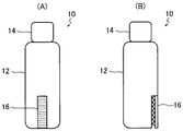
図1(A)および図1(B)に、本発明の構造体を利用する、本発明の容器の一例を概念的に示す。
なお、図1(A)は本発明の容器の正面図であり、図1(B)は、側面図である。正面図は、本発明の特徴である残量確認部16を正面から見た図であり、側面図は、図1(A)の正面図に対して、上下方向を軸に容器を90°回転した図である。上下方向とは、容器10を通常の状態で載置した際に、鉛直方向となる方向である。
1A and 1B conceptually show an example of the container of the present invention using the structure of the present invention.
1A is a front view of the container of the present invention, and FIG. 1B is a side view. The front view is a front view of the remaining
図1(A)および図1(B)に示すように、容器10は、容器本体12と、蓋体14と、残量確認部16とを有して構成される。残量確認部16は、本発明の構造体に係るものである。
As shown in FIGS. 1A and 1B, the
図示例において、容器本体12は、内容物Wを収容する略有底筒状のもので、上部に内容物を排出するための筒状の排出口を有している。
また、蓋体14は、容器本体12の排出口を閉塞するためのものであり、螺合や凹凸を利用する嵌合等の公知の手段によって、排出口となる筒状部に着脱可能に構成され、容器本体12の排出口を閉塞および開放する。
In the example of illustration, the container
The
容器10は、本発明の構造体に係る残量確認部16を有する以外には、基本的に、化粧品、薬品、飲食物等の各種の液体、粉体、粒状物、ゲル状物、ペースト状物等の各種の物品を収容する、公知の容器である。
従って、容器本体12および蓋体14の形状や大きさ、構成、形成材料等には、限定はない。また、本発明の容器は、容器本体12と蓋体14とから構成される物に限定はされず、例えば、中蓋を有してもよく、スプレーによって内容物を排出するものであってもよく、取り外しができない揺動する蓋体によって排出口を開閉するものであってもよい。
The
Accordingly, there is no limitation on the shape, size, configuration, forming material, and the like of the
この容器10は、紫外線等の光によって劣化する内容物Wの収納に適した容器であり、蓋体14は遮光性を有し、容器本体12は、残量確認部16の配置位置以外は、遮光性を有する。
なお、容器本体12および蓋体14を遮光性にする方法は、容器本体12および蓋体14に遮光性を付与できる塗料を塗布する方法、容器本体12および蓋体14を遮光性の包装材で包む方法、容器本体12および蓋体14を遮光性を確保できる材料で形成する方法等、公知の方法が各種利用可能である。
The
In addition, the method of making the container
ここで、容器10は、容器本体12の残量確認部16の配置位置において、残量確認部16により光の反射と透過とを切り替えて、容器本体12内の内容物Wの残量を確認するものである。そのため、容器本体12は、残量確認部16の配置位置に光透過性を有する光透過部12aを有する。
したがって、容器本体12を遮光性にする方法としては、遮光性を有する部分と光透過性を有する部分とを容易に形成できる観点から、遮光性を付与できる塗料を塗布する方法、および、遮光性の包装材で包む方法が好適である。
Here, the
Therefore, as a method for making the
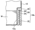
また、図示例においては、容器本体12の底面近傍の側面に、凹部を有する。この凹部は、残量確認部16の配置位置であり、凹部の形状は残量確認部16の形状に対応して形成される。したがって、この凹部の内側の壁面が上述の光透過部12aとなる。
Moreover, in the example of illustration, it has a recessed part in the side surface vicinity of the bottom face of the container
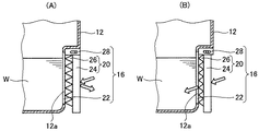
ここで、図示例においては、容器本体12の壁面の一部である光透過部12aが、第1透明板22の機能を兼ねている。しかしながら、これに限定はされず、図3に示すように、光透過部12aの外側面に配置される第1透明板22を有する構成としてもよい。
第1透明板22については後に詳述する。
Here, in the illustrated example, the
The first
図2(A)に、容器10の残量確認部16を拡大した断面図を示す。
残量確認部16は、本発明の構造体であり、図2(A)に示すように、基材24と再帰性反射構造層26とを有する第2透明板20、第1透明板22、および、案内部材28を有して構成される。
また、図1(A)および図1(B)に示されるように、残量確認部16は、一例として、直方体状の形状を有する。
FIG. 2A shows an enlarged cross-sectional view of the remaining
The remaining
Moreover, as FIG. 1 (A) and FIG.1 (B) show, the residual
このような残量確認部16は、通常状態では、図2(A)で矢印で示すように、第2透明板20の再帰性反射構造層26により、光を再帰反射させるので、遮光性を有する。一方、図2(B)に示すように、第2透明板20を第1透明板22に押圧することで、第2透明板20と第1透明板22との間で再帰性反射構造層26が押圧されて、再帰性反射構造層26が変形して、光が反射するのが抑制され、図中矢印で示すように、光を透過するようになる。
残量確認部16は、このように、第2透明板20を第1透明板22に押圧することで、光の反射と透過とを切り替える機能を有する部位である。
この点に関しては後に詳述する。
In the normal state, such a remaining
Thus, the remaining
This will be described in detail later.
第1透明板22および第2透明板20は、本発明における1組の透明板である。
The first
第1透明板22は、第2透明板20の再帰性反射構造層26側に対面して設けられる、透明性を有し、最大面が長方形状の板状部材である。
前述のとおり、第1透明板22として、容器本体12の側面の一部(光透過部12a)を用いることも可能である。
また、図3に示すように第1透明板22を容器本体12とは別に設ける場合には、第1透明板22は、容器本体12の光透過部12aの外側面に固定される。
The first
As described above, a part of the side surface of the container body 12 (
As shown in FIG. 3, when the first
第1透明板22の透明度には、特に限定はなく、残量確認部16が透過状態になった際に、容器本体12が収容している内容物Wを視認できればよい。特に、残量確認部16が透過状態になった際に、容器本体12が収容している内容物の液面が視認できればよい。
The transparency of the first
第1透明板22の形成材料としては、透明性と適度な剛性を有するものであれば限定はなく、ポリエチレンテレフタレート(PET)、ポリ塩化ビニル(PVC)、透明ポリイミド、ポリメタクリル酸メチル樹脂(PMMA)、ポリカーボネート(PC)等の樹脂材料、ソーダライムガラス、硼珪酸ガラス、光学ガラスなどの各種のガラスなどが各種利用可能である。
The material for forming the first
また、第1透明板22の大きさ、厚さ等にも限定はなく、容器10の大きさ、用途、残量確認部16の大きさ等に応じて適宜、設定すればよい。
Moreover, there is no limitation also in the magnitude | size, thickness, etc. of the 1st
第2透明板20は、第1透明板22に対面して配置されるものであり、基材24と、基材24の第1透明板22と対面する面に形成された再帰性反射構造層26とを有する。すなわち、第2透明板20は、再帰性反射構造層26側の面を容器本体12に向けて配置される。
The second
この第2透明板20は、案内部材28によって、第2透明板20の主面に垂直な方向に移動可能に支持されている。したがって、第2透明板20を第1透明板22の方向に移動させて、第2透明板20を第1透明板22に押圧することができる。
The second
基材24は、透明性を有し、最大面が長方形の板状部材であり、一面に再帰性反射構造層26が積層されたものである。
基材24は上述の第1透明板22と同様の透明度を有するのが好ましい。
また、基材24の形成材料としては、透明性と適度な剛性を有するものであれば限定はなく、上述した第1透明板22と同様の材料が利用可能である。
また、第1透明板22の大きさ、厚さ等にも限定はなく、容器10の大きさ、用途、残量確認部16の大きさ等に応じて適宜、設定すればよい。
The
The
The material for forming the
Moreover, there is no limitation also in the magnitude | size, thickness, etc. of the 1st
再帰性反射構造層26は、基材24の一面に積層された、基材24側から入射した光を入射方向に反射する再帰性反射を行う再帰性反射構造が形成された層である。
The
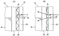
周知のように、再帰性反射構造とは、入射した光が、再度、入射方向に帰るように光を反射する構造である。
図示例においては、一例として、長尺なプリズム(三角柱)を稜線と直交する方向に配列した、いわゆるプリズムシート状(プリズム構造)の再帰性反射構造を有している。具体的には、プリズムの稜線を、図1(A)の図中横方向、図1(B)、図2(A)および図2(B)の紙面に垂直方向に一致して、図中上下方向にプリズムを配列した、再帰性反射構造を有している。また、プリズムは、一例として、頂角が90°の二等辺三角形の底面を有し、頂角を第1透明板22に向けて配列される。
As is well known, the retroreflective structure is a structure that reflects light so that incident light returns to the incident direction again.
The illustrated example has a so-called prism sheet (prism structure) retroreflective structure in which long prisms (triangular prisms) are arranged in a direction orthogonal to the ridgeline. Specifically, the prism ridge line is aligned with the horizontal direction in the drawing of FIG. 1A and in the vertical direction to the paper surface of FIGS. 1B, 2A, and 2B. It has a retroreflective structure in which prisms are arranged in the vertical direction. For example, the prism has a bottom surface of an isosceles triangle having an apex angle of 90 °, and the apex angle is arranged toward the first
なお、図1(A)では、再帰性反射構造を説明するために、残量確認部16において、再帰性反射構造を形成するプリズムの稜線を破線で示している。
しかしながら、後述するように、残量確認部16は、通常時には再帰性反射による全反射構造となっているため、容器外部からの目視的には、金属光沢面のようになっている。また、残量確認部16は、容器本体12内に収容される内容物の残量を確認する際には、透明になっている。
従って、残量確認部16の再帰性反射構造は、基本的に、使用者に目視されない。
In FIG. 1A, in order to describe the retroreflective structure, a ridge line of the prism forming the retroreflective structure is indicated by a broken line in the remaining
However, as will be described later, the remaining
Therefore, the retroreflective structure of the remaining
ここで、本発明において、再帰性反射構造層26は弾性を有する。
本発明の構造体である残量確認部16は、再帰性反射構造層26が弾性を有するので、第2透明板20の再帰性反射構造層26を第1透明板22に押圧して、再帰性反射構造層26を変形することで、光の反射と透過とを切り替えることができる。
Here, in the present invention, the
Since the
一例として、再帰性反射構造層26が屈折率1.5であったとする。また、周知のように、空気の屈折率は約1.0である。
図4(A)に概念的に示すように、第1透明板22と第2透明板20とが離間している、あるいは、再帰性反射構造層26の頂部のみが第1透明板22と接している通常の状態では、第2透明板20の再帰性反射構造層26は、空気と接触している。従って、この状態では、第2透明板20から空気に入射する光の臨界角は41.8°である。
前述のように、再帰性反射構造を構成するプリズムは、頂角θ1が90°の二等辺三角形である。従って、例えば残量確認部16に正面から入射した光Lの入射角θ2は45°で、臨界角よりも小さいため、光Lは全反射される。すなわち、図3(A)に示す状態では、残量確認部16は、光Lを全反射する、金属光沢状態のようになっており、残量確認部16から容器本体12の内部に光Lが入射することを防止でき、容器10の遮光性は維持されている。
以下の説明では、残量確認部16が光を反射する状態を単に『反射状態』とも言う。
As an example, assume that the
As conceptually shown in FIG. 4A, the first
As described above, the prism constituting the retroreflective structure is an isosceles triangle having an apex angle θ 1 of 90 °. Therefore, for example, the incident angle θ 2 of the light L incident on the remaining
In the following description, the state in which the remaining
一方、図4(B)に示すように、第2透明板20の再帰性反射構造層26を第1透明板22に押圧することで、再帰性反射構造層26が変形する。この変形により、再帰性反射構造をなすプリズムの頂角θ1が大きくなり、残量確認部16に正面から入射した光Lの入射角θ2が、臨界角よりも小さくなる。そのため、残量確認部16に正面から入射した光Lは反射されず、再帰性反射構造層26と空気との界面を透過して、容器本体12の光透過部12aを透過して、容器本体12内に到る。
従って、この状態では、残量確認部16は光が透過可能な透明な状態になっており、使用者は、外部から容器本体12の内部を視認して、内容物の残量を確認できる。
以下の説明では、残量確認部16が光を透過する状態を単に『透過状態』とも言う。
On the other hand, as shown in FIG. 4B, the
Therefore, in this state, the remaining
In the following description, the state in which the remaining
すなわち、残量確認部16として本発明の構造体を利用する容器10は、通常は遮光性を維持しつつ、必要に応じて、使用者が残量確認部16から内部を目視して、内容物の残量を確認し、確認後、再度、遮光状態に戻すことができる。
しかも、本発明によれば、反射状態は、基本的に正面から入射した光Lを全反射するため、残量確認部16は、外観的には金属光沢面のようになっており、他方、透過状態では、基本的に正面から入射した光Lをほぼ透過する。
このように、本発明の構造体である残量確認部16は、光の反射と透過とを容易に切り替えることができ、通常の状態(反射状態)では、光を反射して容器本体12内に紫外線等の光が侵入するのを防止して、内容物Wが光によって劣化するのを防止でき、かつ、第2透明板20を押圧することにより、内容物Wの残量を確認することができる。また、金属光沢により、遮光時の意匠を高める効果もある。
That is, the
Moreover, according to the present invention, since the reflection state basically totally reflects the light L incident from the front, the remaining
As described above, the remaining
再帰性反射構造層26の弾性率は、基材24の弾性率よりも低いことが好ましく、また、第1透明板22の弾性率よりも低いことが好ましい。すなわち、再帰性反射構造層26は、基材24および第1透明板22よりも変形しやすいことが好ましい。
再帰性反射構造層26の弾性率を基材24および第1透明板22の弾性率よりも低くすることで、第2透明板20を第1透明板22に押圧した際に、再帰性反射構造層26が変形しやすくなり、再帰性反射構造が崩れやすくなるので、光の透過と反射とをより好適に切り替えることができる。
The elastic modulus of the
By making the elastic modulus of the
再帰性反射構造を変形しやすくできる等の観点から再帰性反射構造層26の弾性率は、0.1MPa〜100MPaが好ましく、1MPa〜10MPaがより好ましい。
From the viewpoint that the retroreflective structure can be easily deformed, the elastic modulus of the
再帰性反射構造層26の形成材料としては、透明性を有し、かつ、弾性を有するものであればよく、ジメチルポリシロキサン(PDMS)等のシリコーン樹脂、高透明ウレタンゴム、アクリルゴム、ブチルゴム等が好適に利用可能である。
なかでも、透明性および弾性率の観点から、PDMSが好ましい。
The material for forming the
Of these, PDMS is preferable from the viewpoint of transparency and elastic modulus.
また、反射状態で、再帰性反射構造に好適に全反射を起こさせるためには、再帰性反射構造層26は、気体(屈折率は概ね約1.0)よりも、ある程度、大きな屈折率を有する材料で形成するのが好ましい。なお、この気体には、空気も含む。
ここで、後述する再帰性反射構造におけるプリズム等の頂角にもよるが、後述するように、この頂角が80〜100°が好ましい点を考慮すると、再帰性反射構造層26の形成材料は、屈折率が1.3以上であるのが好ましく、1.5以上であるのがより好ましい。
Further, in order to cause total reflection suitably in the retroreflective structure in the reflective state, the
Here, although it depends on the apex angle of the prism or the like in the retroreflective structure described later, the material for forming the
図示例の再帰性反射構造層26は、底面が頂角90°の二等辺三角形である長尺なプリズムを稜線と直交する方向に配列してなる構成を有するものである。
しかしながら、本発明は、これに限定はされず、例えば球体や半球体を規則的あるいは不規則に配列してなる再帰性反射構造など、公知の再帰性反射構造が、各種、利用可能である。
The
However, the present invention is not limited to this, and various known retroreflective structures such as a retroreflective structure in which spheres and hemispheres are regularly or irregularly arranged can be used.
中でも、図示例のような底面が二等辺三角形である長尺なプリズムを配列してなる再帰性反射構造、および、錐体を規則的あるいは不規則に配列してなる再帰性反射構造は、好適に例示される。
その中でも特に、図示例のような底面が二等辺三角形である長尺なプリズムを配列してなる再帰性反射構造、正四角錐や正三角錐などの正角錐を規則的あるいは不規則に配列してなる再帰性反射構造、円錐を規則的あるいは不規則に配列してなる再帰性反射構造は、好適に利用される。
このような再帰性反射構造を利用することにより、反射状態における残量確認部16の光反射率を向上して、残量確認部16の遮光性をより向上できる、遮光時の意匠性を高める事が出来る等の点で好ましい。
Among them, a retroreflective structure in which long prisms whose bottoms are isosceles triangles as shown in the example are arranged, and a retroreflective structure in which cones are regularly or irregularly arranged are suitable. Is exemplified.
Among them, in particular, a retroreflective structure in which long prisms whose bases are isosceles triangles are arranged as in the illustrated example, regular pyramids such as regular quadrangular pyramids and regular triangular pyramids are arranged regularly or irregularly. A retroreflective structure or a retroreflective structure in which cones are regularly or irregularly arranged is preferably used.
By using such a retroreflective structure, the light reflectivity of the remaining
なお、本発明に利用される再帰性反射構造においては、必要に応じて、プリズムと正四角錐の併用、プリズムと円錐との併用など、複数の異なる形状を併用して、再帰性反射構造を構成してもよい。 In the retroreflective structure used in the present invention, the retroreflective structure is configured by using a plurality of different shapes together, such as a combination of a prism and a regular quadrangular pyramid and a combination of a prism and a cone, as necessary. May be.
本発明において、再帰性反射構造が、プリズムのような三角柱を配列してなる構成である場合や、錐体を配列してなる構成である場合には、三角柱の頂角すなわち第1透明板22に対面する頂点の角度、および、錐体の頂点を通過する底面に垂直な三角形の頂角が、80〜100°であるのが好ましく、85°〜95°であるのがより好ましい。
頂角を80°以上にすることにより、光Lの入射角が大きくなりすぎることに起因して、透過状態でも入射角が臨界角以上になって光Lを反射して透明性を低減することを防止できる等の点で好ましい。
また、頂角を100°以下にすることにより、光Lの入射角が小さくなりすぎることに起因して、反射状態でも入射角が臨界角未満になって光Lが容器本体12内に入射することを防止できる等の点で好ましい。
In the present invention, when the retroreflective structure has a configuration in which triangular prisms such as prisms are arranged, or in a configuration in which cones are arranged, the apex angle of the triangular prisms, that is, the first
By making the apex angle 80 ° or more, the incident angle of the light L becomes too large, so that the incident angle becomes more than the critical angle even in the transmission state and the light L is reflected to reduce transparency. This is preferable in that it can be prevented.
Further, by setting the apex angle to 100 ° or less, the incident angle of the light L becomes too small, so that the incident angle becomes less than the critical angle even in the reflection state, and the light L enters the
なお、前述のように、図示例においては、稜線を横方向に向けて長尺なプリズムを配列している。
しかしながら、本発明では、再帰性反射構造が長尺なプリズムを配列する構成である場合には、稜線を上下方向にして、長尺なプリズムを配列した構成でもよく、あるいは、鉛直方向に対して稜線を傾斜させて、長尺なプリズムを配列した構成としてもよい。
As described above, in the illustrated example, the long prisms are arranged with the ridge line in the horizontal direction.
However, in the present invention, when the retroreflective structure is a configuration in which long prisms are arranged, a configuration in which long prisms are arranged with the ridge line in the vertical direction may be used, or with respect to the vertical direction. A configuration in which long prisms are arranged by inclining the ridgeline may be employed.
また、再帰性反射構造を構成するプリズムや錐体の高さ、幅、長さ、あるいは、プリズムや錐体の配列周期等には限定はなく、残量確認部16の大きさ、再帰性反射構造層26や基材24、第2透明板20の形成材料等に応じて、適宜、設定すればよい。
Further, there is no limitation on the height, width and length of the prisms and cones constituting the retroreflective structure, or the arrangement period of the prisms and cones, and the size of the remaining
このような再帰性反射構造の形成方法には限定はなく、射出成型、圧縮成形、インプリント、切削加工等の公知の方法で形成することができる。 There is no limitation in the formation method of such a retroreflection structure, It can form by well-known methods, such as injection molding, compression molding, imprint, and cutting.
また、上記例では、第2透明板20は、再帰性反射構造層26と基材24とからなる構成としたが、これに限定はされず、一体的に形成されたものでもよい。すなわち、再帰性反射構造を有する第2透明板20全体が弾性を有する構成であってもよい。
Moreover, in the said example, although the 2nd
案内部材28は、第2透明板20を、第2透明板20(基材24)の主面に垂直な方向に移動可能に支持するものである。すなわち、案内部材28は、第2透明板20を第1透明板22側に移動可能に支持する。
案内部材28の構成としては限定はなく、従来、ガイド機構として用いられている構成が各種利用可能である。例えば、案内部材28が、第2透明板20の主面に垂直な方向に延在する溝を有し、第2透明板20がこの溝に係合する突起部を有することで、第2透明板20を第1透明板22側に移動可能に支持できる。
あるいは、案内部材28が、第2透明板20の一方の端部を回転可能に支持して、第2透明板20が第1透明板22側へ揺動するように支持する構成としてもよい。
あるいは、ゴムや弾性を有する樹脂などの弾性体、または、コイルスプリングなどのバネ部材を、第1透明板22と第2透明板20との間に配置する構成としてもよい。
The
The configuration of the
Alternatively, the
Alternatively, an elastic body such as rubber or elastic resin or a spring member such as a coil spring may be disposed between the first
なお、図示例の容器10においては、残量確認部16は、容器本体12の底面近傍の側面に配置される構成としたが、これに限定はされず、例えば、容器本体12の排出口近傍に配置される構成としてもよい。残量確認部16が容器本体12の排出口近傍に配置される場合には、排出口を蓋体14で閉塞したまま、容器10を鉛直方向に逆さまにして、残量確認部16を押圧して内容物Wの残量の確認を行えばよい。
In the
また、上述の例では、第2透明板20が移動可能に支持される構成としたが、これに限定はされず、第1透明板22が移動可能に支持される構成であってもよく、あるいは、第1透明板22と第2透明板20の両方が移動可能に支持される構成であってもよい。
In the above example, the second
以上の例は、本発明の構造体を化粧品等の容器に利用した例であるが、本発明の構造体は、第1透明板の再帰性反射構造を第2透明板に押圧することで、迅速かつ簡易に反射状態と透過状態とを切り換えられることを利用して、各種の用途に利用可能である。
一例として、反射状態と透過状態とを切り換えることができる、いわゆる調光窓や調光ガラスが例示される。
なお、本発明の構造体を調光窓や調光ガラスのように、ある程度の大きさを有する部材に利用する場合には、電動モータ等の駆動源を利用して第1透明板22あるいは第2透明板20を移動する構成としてもよい。
The above example is an example in which the structure of the present invention is used for a container such as a cosmetic, but the structure of the present invention is by pressing the retroreflective structure of the first transparent plate against the second transparent plate, It can be used for various applications by utilizing the fact that it can switch between the reflection state and the transmission state quickly and easily.
As an example, a so-called dimming window or dimming glass capable of switching between a reflection state and a transmission state is exemplified.
When the structure of the present invention is used for a member having a certain size, such as a light control window or light control glass, the first
以上、本発明の構造体および容器について詳細に説明したが、本発明は、上述の例に限定はされず、本発明の要旨を逸脱しない範囲において、各種の改良や変更を行ってもよいのは、もちろんである。 As mentioned above, although the structure and container of this invention were demonstrated in detail, this invention is not limited to the above-mentioned example, In the range which does not deviate from the summary of this invention, you may perform various improvement and a change. Of course.
化粧品等を収容する容器、調光ガラスや調光窓等に、好適に利用可能である。 It can be suitably used for containers for storing cosmetics, light control glasses, light control windows, and the like.
10 容器
12 容器本体
12a 光透過部
14 蓋体
16、16b 残量確認部(構造体)
20 第1透明板
22 第2透明板
24 基材
26 再帰性反射構造層
28 案内部材
DESCRIPTION OF
20 first
Claims (8)
前記透明板の少なくとも一方が、他方の前記透明板に接離可能に支持されており、
かつ、前記再帰性反射構造が弾性を有する構造体を壁面に有する容器であって、
前記壁面の、前記構造体の配置位置は光透過性を有し、それ以外の壁面は遮光性を有する容器。 Having one set of transparent plates arranged opposite to each other, one transparent plate having a retroreflective structure on the surface facing the other transparent plate,
At least one of the transparent plates is supported so as to be able to contact and separate from the other transparent plate,
And the retroreflective structure is a container having a wall surface structure Zotai that having a resilient,
An arrangement position of the structure on the wall surface is light-transmitting, and other wall surfaces are light-shielding.
Priority Applications (1)
| Application Number | Priority Date | Filing Date | Title |
|---|---|---|---|
| JP2015185461A JP6463243B2 (en) | 2015-09-18 | 2015-09-18 | container |
Applications Claiming Priority (1)
| Application Number | Priority Date | Filing Date | Title |
|---|---|---|---|
| JP2015185461A JP6463243B2 (en) | 2015-09-18 | 2015-09-18 | container |
Publications (2)
| Publication Number | Publication Date |
|---|---|
| JP2017058609A JP2017058609A (en) | 2017-03-23 |
| JP6463243B2 true JP6463243B2 (en) | 2019-01-30 |
Family
ID=58390099
Family Applications (1)
| Application Number | Title | Priority Date | Filing Date |
|---|---|---|---|
| JP2015185461A Active JP6463243B2 (en) | 2015-09-18 | 2015-09-18 | container |
Country Status (1)
| Country | Link |
|---|---|
| JP (1) | JP6463243B2 (en) |
Families Citing this family (1)
| Publication number | Priority date | Publication date | Assignee | Title |
|---|---|---|---|---|
| KR102218902B1 (en) * | 2020-08-31 | 2021-02-22 | 김정모 | foot pedal type hand sterilizer |
Family Cites Families (6)
| Publication number | Priority date | Publication date | Assignee | Title |
|---|---|---|---|---|
| CN2642300Y (en) * | 2003-08-07 | 2004-09-22 | 高磊 | Eye drops bottle |
| JP5515228B2 (en) * | 2008-03-14 | 2014-06-11 | 日立化成株式会社 | Optical film and manufacturing method thereof |
| JP5515227B2 (en) * | 2008-03-14 | 2014-06-11 | 日立化成株式会社 | Optical film |
| JP2010159085A (en) * | 2008-12-12 | 2010-07-22 | Mitsuya Corporation:Kk | Decorative item and container with food- or content-accommodating portion able to transmit visible light |
| BR112015018001A8 (en) * | 2013-01-28 | 2019-11-05 | 3M Innovative Properties Co | retroreflective blade and method for manufacturing a retroreflective article |
| CN204507581U (en) * | 2015-03-09 | 2015-07-29 | 上海嘉妍健康科技有限公司 | Liquid packaging bottle |
-
2015
- 2015-09-18 JP JP2015185461A patent/JP6463243B2/en active Active
Also Published As
| Publication number | Publication date |
|---|---|
| JP2017058609A (en) | 2017-03-23 |
Similar Documents
| Publication | Publication Date | Title |
|---|---|---|
| CN214083864U (en) | Dynamically Bendable Automotive Interior Display System | |
| CN114007888B (en) | Display components for automotive interiors | |
| KR100954054B1 (en) | PET Bottle Drinkware | |
| JPWO2017010252A1 (en) | Liquid seasoning container and containerized liquid seasoning | |
| JP6141432B2 (en) | Optical film and digital pen system using the same | |
| KR20220124086A (en) | content container | |
| JP2012000381A (en) | Cosmetic container | |
| JP2016117528A (en) | Decorative plastic molding, and method for manufacturing the same | |
| JP6463243B2 (en) | container | |
| JPWO2019123896A1 (en) | Transparent screen, video projection mating board, and video display system | |
| JP6584256B2 (en) | Structures and containers | |
| JP2017056994A (en) | Structures and containers | |
| KR101513376B1 (en) | Container having transparent optical element | |
| JP5637432B2 (en) | Synthetic resin blow molding housing | |
| EP2129584A2 (en) | Oral care package | |
| KR20160023028A (en) | a cosmetic tube vessel | |
| JP6245747B2 (en) | Cap and manufacturing method thereof | |
| JP7784794B2 (en) | Extrusion blown containers | |
| JP6851771B2 (en) | Resin container | |
| JP6851772B2 (en) | Resin container | |
| JP7674944B2 (en) | Soft packaging holder | |
| RU28861U1 (en) | TRANSPARENT CAPACITY FOR LIQUID | |
| JP3210594U7 (en) | ||
| KR101733474B1 (en) | Container | |
| JP6893743B2 (en) | Container with lid |
Legal Events
| Date | Code | Title | Description |
|---|---|---|---|
| A621 | Written request for application examination |
Free format text: JAPANESE INTERMEDIATE CODE: A621 Effective date: 20170810 |
|
| A977 | Report on retrieval |
Free format text: JAPANESE INTERMEDIATE CODE: A971007 Effective date: 20180516 |
|
| A131 | Notification of reasons for refusal |
Free format text: JAPANESE INTERMEDIATE CODE: A131 Effective date: 20180529 |
|
| TRDD | Decision of grant or rejection written | ||
| A01 | Written decision to grant a patent or to grant a registration (utility model) |
Free format text: JAPANESE INTERMEDIATE CODE: A01 Effective date: 20181225 |
|
| A61 | First payment of annual fees (during grant procedure) |
Free format text: JAPANESE INTERMEDIATE CODE: A61 Effective date: 20181228 |
|
| R150 | Certificate of patent or registration of utility model |
Ref document number: 6463243 Country of ref document: JP Free format text: JAPANESE INTERMEDIATE CODE: R150 |
|
| R250 | Receipt of annual fees |
Free format text: JAPANESE INTERMEDIATE CODE: R250 |
|
| R250 | Receipt of annual fees |
Free format text: JAPANESE INTERMEDIATE CODE: R250 |
|
| R250 | Receipt of annual fees |
Free format text: JAPANESE INTERMEDIATE CODE: R250 |
|
| R250 | Receipt of annual fees |
Free format text: JAPANESE INTERMEDIATE CODE: R250 |