JP6461069B2 - Control device for internal combustion engine - Google Patents
Control device for internal combustion engine Download PDFInfo
- Publication number
- JP6461069B2 JP6461069B2 JP2016226938A JP2016226938A JP6461069B2 JP 6461069 B2 JP6461069 B2 JP 6461069B2 JP 2016226938 A JP2016226938 A JP 2016226938A JP 2016226938 A JP2016226938 A JP 2016226938A JP 6461069 B2 JP6461069 B2 JP 6461069B2
- Authority
- JP
- Japan
- Prior art keywords
- valve
- internal combustion
- combustion engine
- energization
- opening
- Prior art date
- Legal status (The legal status is an assumption and is not a legal conclusion. Google has not performed a legal analysis and makes no representation as to the accuracy of the status listed.)
- Expired - Fee Related
Links
Images

Classifications
-
- F—MECHANICAL ENGINEERING; LIGHTING; HEATING; WEAPONS; BLASTING
- F02—COMBUSTION ENGINES; HOT-GAS OR COMBUSTION-PRODUCT ENGINE PLANTS
- F02B—INTERNAL-COMBUSTION PISTON ENGINES; COMBUSTION ENGINES IN GENERAL
- F02B37/00—Engines characterised by provision of pumps driven at least for part of the time by exhaust
- F02B37/12—Control of the pumps
- F02B37/18—Control of the pumps by bypassing exhaust from the inlet to the outlet of turbine or to the atmosphere
- F02B37/183—Arrangements of bypass valves or actuators therefor
-
- F—MECHANICAL ENGINEERING; LIGHTING; HEATING; WEAPONS; BLASTING
- F02—COMBUSTION ENGINES; HOT-GAS OR COMBUSTION-PRODUCT ENGINE PLANTS
- F02B—INTERNAL-COMBUSTION PISTON ENGINES; COMBUSTION ENGINES IN GENERAL
- F02B37/00—Engines characterised by provision of pumps driven at least for part of the time by exhaust
- F02B37/12—Control of the pumps
- F02B37/18—Control of the pumps by bypassing exhaust from the inlet to the outlet of turbine or to the atmosphere
-
- B—PERFORMING OPERATIONS; TRANSPORTING
- B60—VEHICLES IN GENERAL
- B60W—CONJOINT CONTROL OF VEHICLE SUB-UNITS OF DIFFERENT TYPE OR DIFFERENT FUNCTION; CONTROL SYSTEMS SPECIALLY ADAPTED FOR HYBRID VEHICLES; ROAD VEHICLE DRIVE CONTROL SYSTEMS FOR PURPOSES NOT RELATED TO THE CONTROL OF A PARTICULAR SUB-UNIT
- B60W20/00—Control systems specially adapted for hybrid vehicles
- B60W20/40—Controlling the engagement or disengagement of prime movers, e.g. for transition between prime movers
-
- B—PERFORMING OPERATIONS; TRANSPORTING
- B60—VEHICLES IN GENERAL
- B60W—CONJOINT CONTROL OF VEHICLE SUB-UNITS OF DIFFERENT TYPE OR DIFFERENT FUNCTION; CONTROL SYSTEMS SPECIALLY ADAPTED FOR HYBRID VEHICLES; ROAD VEHICLE DRIVE CONTROL SYSTEMS FOR PURPOSES NOT RELATED TO THE CONTROL OF A PARTICULAR SUB-UNIT
- B60W50/00—Details of control systems for road vehicle drive control not related to the control of a particular sub-unit, e.g. process diagnostic or vehicle driver interfaces
- B60W2050/0062—Adapting control system settings
- B60W2050/0075—Automatic parameter input, automatic initialising or calibrating means
- B60W2050/0083—Setting, resetting, calibration
- B60W2050/0086—Recalibrating datum positions, e.g. by using check cycles
-
- B—PERFORMING OPERATIONS; TRANSPORTING
- B60—VEHICLES IN GENERAL
- B60W—CONJOINT CONTROL OF VEHICLE SUB-UNITS OF DIFFERENT TYPE OR DIFFERENT FUNCTION; CONTROL SYSTEMS SPECIALLY ADAPTED FOR HYBRID VEHICLES; ROAD VEHICLE DRIVE CONTROL SYSTEMS FOR PURPOSES NOT RELATED TO THE CONTROL OF A PARTICULAR SUB-UNIT
- B60W2710/00—Output or target parameters relating to a particular sub-units
- B60W2710/06—Combustion engines, Gas turbines
- B60W2710/0638—Turbocharger state
-
- B—PERFORMING OPERATIONS; TRANSPORTING
- B60—VEHICLES IN GENERAL
- B60Y—INDEXING SCHEME RELATING TO ASPECTS CROSS-CUTTING VEHICLE TECHNOLOGY
- B60Y2400/00—Special features of vehicle units
- B60Y2400/43—Engines
- B60Y2400/435—Supercharger or turbochargers
-
- Y—GENERAL TAGGING OF NEW TECHNOLOGICAL DEVELOPMENTS; GENERAL TAGGING OF CROSS-SECTIONAL TECHNOLOGIES SPANNING OVER SEVERAL SECTIONS OF THE IPC; TECHNICAL SUBJECTS COVERED BY FORMER USPC CROSS-REFERENCE ART COLLECTIONS [XRACs] AND DIGESTS
- Y02—TECHNOLOGIES OR APPLICATIONS FOR MITIGATION OR ADAPTATION AGAINST CLIMATE CHANGE
- Y02T—CLIMATE CHANGE MITIGATION TECHNOLOGIES RELATED TO TRANSPORTATION
- Y02T10/00—Road transport of goods or passengers
- Y02T10/10—Internal combustion engine [ICE] based vehicles
- Y02T10/12—Improving ICE efficiencies
-
- Y—GENERAL TAGGING OF NEW TECHNOLOGICAL DEVELOPMENTS; GENERAL TAGGING OF CROSS-SECTIONAL TECHNOLOGIES SPANNING OVER SEVERAL SECTIONS OF THE IPC; TECHNICAL SUBJECTS COVERED BY FORMER USPC CROSS-REFERENCE ART COLLECTIONS [XRACs] AND DIGESTS
- Y02—TECHNOLOGIES OR APPLICATIONS FOR MITIGATION OR ADAPTATION AGAINST CLIMATE CHANGE
- Y02T—CLIMATE CHANGE MITIGATION TECHNOLOGIES RELATED TO TRANSPORTATION
- Y02T10/00—Road transport of goods or passengers
- Y02T10/10—Internal combustion engine [ICE] based vehicles
- Y02T10/40—Engine management systems
Landscapes
- Engineering & Computer Science (AREA)
- Mechanical Engineering (AREA)
- Chemical & Material Sciences (AREA)
- Combustion & Propulsion (AREA)
- General Engineering & Computer Science (AREA)
- Automation & Control Theory (AREA)
- Transportation (AREA)
- Supercharger (AREA)
- Output Control And Ontrol Of Special Type Engine (AREA)
- Hybrid Electric Vehicles (AREA)
Description
本発明は、吸気を過給する過給機のタービンをバイパスするバイパス通路に設けられ、過給機による過給圧を調整するためのウェイストゲート弁を有する内燃機関の制御装置に関する。 The present invention relates to a control device for an internal combustion engine having a wastegate valve that is provided in a bypass passage that bypasses a turbine of a supercharger that supercharges intake air, and that adjusts a supercharging pressure by the supercharger.
従来の内燃機関の制御装置として、例えば特許文献1に記載されたものが知られている。この内燃機関は、車両に駆動源として搭載されるとともに、電動のアクチュエータを有するウェイストゲート弁を備えている。この車両では、所定の自動停止条件が成立したときに内燃機関を自動停止させるアイドルストップ制御が実行される。また、この制御装置では、内燃機関を自動停止させる際、燃料噴射弁からの燃料の供給を停止した後に、アクチュエータの通電によりウェイストゲート弁を閉弁させるとともに、自動停止中、再始動条件が成立するまで、ウェイストゲート弁の閉弁状態が保持される。
As a conventional control device for an internal combustion engine, for example, one described in
上記の従来の制御装置のように、内燃機関の自動停止中、ウェイストゲート弁を閉弁状態に保持する場合には、その後に内燃機関が再始動される際の、内燃機関の振動の影響によるウェイストゲート弁の振動とそれによる不具合、例えばウェイストゲート弁がバイパス通路の内壁などに当接する(当たる)ことによる雑音の発生や弁体の劣化などを防止するために、アクチュエータの通電量を大きくし、ウェイストゲート弁を全閉位置に強く押し付けるのが通常である。しかし、その場合には、消費電力が増大するだけでなく、アクチュエータから電磁波ノイズが発生するおそれがある。 When the wastegate valve is held in the closed state during the automatic stop of the internal combustion engine as in the above-described conventional control device, it is caused by the influence of the vibration of the internal combustion engine when the internal combustion engine is restarted thereafter. In order to prevent the vibration of the waste gate valve and its malfunction, for example, noise generation and deterioration of the valve body due to the waste gate valve coming into contact with the inner wall of the bypass passage, etc. Normally, the waste gate valve is strongly pressed to the fully closed position. However, in this case, not only the power consumption increases, but also electromagnetic noise may be generated from the actuator.
このような不具合を回避するために、例えば、自動停止中、ウェイストゲート弁を全閉位置よりも若干開き側に制御した場合には、内燃機関を再始動する際に、ウェイストゲート弁を全閉位置に駆動することが必要になるため、再始動後に急加速が要求される場合の過給圧の上昇が遅れてしまい、良好な加速応答性を得ることができない。 In order to avoid such problems, for example, when the waste gate valve is controlled to be slightly opened from the fully closed position during automatic stop, the waste gate valve is fully closed when the internal combustion engine is restarted. Since it is necessary to drive to the position, the increase of the supercharging pressure when a rapid acceleration is required after the restart is delayed, and a good acceleration response cannot be obtained.
さらに、内燃機関とともに電動機を搭載したハイブリッド車両では、その駆動モードの1つとして、電動機のみを駆動源とする電動機駆動モードが選択される。この電動機駆動モードにおいて、上述したウェイストゲート弁の全閉位置からの開き制御を用いた場合には、走行する車両の振動の影響によって、ウェイストゲート弁が振動し、バイパス通路の内壁などに当接することによって、雑音が発生するおそれがある。電動機駆動モードでは特に、内燃機関が停止状態にあるため、雑音が比較的小さい場合でも、運転者や車両の周囲の者に聞こえやすく、商品性の低下が顕著になる。 Furthermore, in a hybrid vehicle equipped with an electric motor together with an internal combustion engine, an electric motor drive mode using only the electric motor as a drive source is selected as one of the drive modes. In this motor drive mode, when the above-described opening control of the waste gate valve from the fully closed position is used, the waste gate valve vibrates due to the influence of the vibration of the traveling vehicle and comes into contact with the inner wall of the bypass passage. This may cause noise. Especially in the electric motor drive mode, since the internal combustion engine is in a stopped state, even if the noise is relatively small, it can be easily heard by the driver and those around the vehicle, and the merchantability is significantly reduced.
本発明は、以上のような課題を解決するためになされたものであり、ウェイストゲート弁を駆動するための消費電力を可能な限り抑制しながら、ウェイストゲート弁の他の部材との当接による雑音の発生やウェイストゲート弁の劣化を防止するとともに、加速応答性を向上させることができる内燃機関の制御装置を提供することを目的とする。 The present invention has been made to solve the above-described problems, and is based on contact with other members of the waste gate valve while suppressing power consumption for driving the waste gate valve as much as possible. It is an object of the present invention to provide a control device for an internal combustion engine that can prevent the generation of noise and the deterioration of a waste gate valve and improve the acceleration response.
この目的を達成するために、本願の請求項1による発明は、吸気を過給する過給機(実施形態における(以下、本項において同じ)ターボチャージャ12)と、過給機のタービン121をバイパスするバイパス通路11に設けられ、過給機による過給圧を調整するためのウェイストゲート弁14とを有する内燃機関の制御装置であって、ウェイストゲート弁14を駆動する電動のアクチュエータ(モータ31)と、要求トルクTRQDを含む内燃機関1の運転状態に応じて、ウェイストゲート弁14の目標開度WGCMDを設定する目標開度設定手段(ECU20、図5のステップ5)と、アクチュエータの通電を制御することによって、ウェイストゲート弁14の開度(弁開度WGO)を制御する制御手段(ECU20、図5)と、を備え、制御手段は、内燃機関の始動中又は目標開度WGCMDが全閉開度に設定された運転状態では、アクチュエータの通電量(通電デューティ比Iduty)をウェイストゲート弁14を全閉位置に押付け可能な所定の通電量(所定値IdSTR)に制御し(ステップ4)、内燃機関1の所定の停止状態(EVモード、アイドルストップ)では、ウェイストゲート弁14を全閉位置に駆動した後にアクチュエータの通電を停止する通電停止制御を実行し(ステップ15、13)、ウェイストゲート弁14の実際の開度(弁開度WGO)を検出する実開度検出手段(弁開度センサ23)をさらに備え、制御手段は、検出された実開度が目標開度WGCMDになるようにフィードバック制御によってアクチュエータの通電量を制御する(ステップ10)とともに、目標開度WGCMDの変更に応じたウェイストゲート弁14の全閉位置からの開弁動作の開始直後には、フィードバック制御に代えてフィードフォワード制御により、アクチュエータの通電量をウェイストゲート弁14を開弁する側の所定の最大値IdMAXに制御すること(ステップ9)を特徴とする。
In order to achieve this object, the invention according to
この構成によれば、アクチュエータの通電を制御することによって、ウェイストゲート弁の開度が制御される。また、内燃機関の始動中又はウェイストゲート弁の目標開度が全閉開度に設定された内燃機関の運転状態では、アクチュエータの通電量が、ウェイストゲート弁を全閉位置に押付け可能な所定の通電量に制御されることによって、ウェイストゲート弁は、全閉位置に押し付けられた状態で確実に保持される。これにより、始動中又は運転中の内燃機関の振動などの影響によってウェイストゲート弁が振動することがなくなり、その結果、ウェイストゲート弁の他の部材との当接、及びそれに起因する雑音の発生やウェイストゲート弁などの劣化を防止することができる。また、ウェイストゲート弁が全閉位置に保持されているため、その状態から急加速が要求された場合に、過給圧を速やかに上昇させることができ、良好な加速応答性を確保することができる。さらに、この場合のアクチュエータの所定の通電量を、ウェイストゲート弁を全閉位置に確実に押付け可能な最小限の通電量とすることによって、消費電力を最小限に抑制できる。 According to this configuration, the opening degree of the waste gate valve is controlled by controlling the energization of the actuator. In addition, when the internal combustion engine is started or when the target opening of the waste gate valve is set to the fully closed opening, the energization amount of the actuator is set to a predetermined value that can push the waste gate valve to the fully closed position. By controlling the energization amount, the waste gate valve is reliably held in a state of being pressed to the fully closed position. As a result, the waste gate valve will not vibrate due to the influence of the vibration of the internal combustion engine during start-up or operation, and as a result, contact with other members of the waste gate valve and generation of noise resulting therefrom It is possible to prevent deterioration of the waste gate valve. In addition, since the waste gate valve is held in the fully closed position, when rapid acceleration is required from that state, the supercharging pressure can be quickly increased, and good acceleration response can be ensured. it can. Furthermore, the power consumption can be suppressed to a minimum by setting the predetermined energization amount of the actuator in this case to the minimum energization amount that can reliably press the waste gate valve to the fully closed position.
また、この構成によれば、内燃機関の所定の停止状態では、通電停止制御が実行されることによって、ウェイストゲート弁を全閉位置に駆動した後、アクチュエータの通電が停止される。停止状態では内燃機関は振動しないので、ウェイストゲート弁を全閉位置に駆動した後にアクチュエータの通電を停止しても、ウェイストゲート弁は全閉位置に保持される。したがって、内燃機関の停止状態においても、ウェイストゲート弁の他の部材との当接とそれに起因する雑音の発生及びウェイストゲート弁の劣化を防止できるとともに、その状態から急加速が要求された場合に、過給圧を速やかに上昇させ、良好な加速応答性を確保することができる。また、アクチュエータの通電が停止され、その間の消費電力は0になるので、上述した内燃機関の始動中などにおける消費電力の抑制とあいまって、消費電力を可能な限り抑制することができる。
さらに、この構成では、アクチュエータの通電量は、検出されたウェイストゲート弁の実開度が目標開度になるようにフィードバック制御によって制御される。このようにアクチュエータの通電量をフィードバック制御で制御する場合には、ウェイストゲート弁の実開度の検出信号の入力や、目標開度と実開度との偏差に応じたフィードバック補正項の算出、それに基づく駆動信号の出力などに時間を要するため、その分、ウェイストゲート弁の動作と過給圧の応答が遅れてしまう。
これに対し、この構成によれば、目標開度の変更に応じたウェイストゲート弁の全閉位置からの開弁動作の開始直後には、フィードバック制御に代えてフィードフォワード制御により、アクチュエータの通電量が、ウェイストゲート弁を開弁する側の所定の最大値に制御される。これにより、上述したフィードバック制御の場合の応答遅れがなくなり、ウェイストゲート弁がより速やかに開弁側に駆動され、開弁時間が短縮される。その結果、上昇した過給圧がより速やかに低下し、上限値を上回る過給圧のオーバーシュートが生じにくくなるので、その分、より大きな過給圧を目標とすることが可能になり、内燃機関の出力を高めることができる。
請求項2に係る発明は、請求項1に記載の内燃機関の制御装置において、制御手段は、ウェイストゲート弁14の全閉位置からの開弁動作の開始直後において、目標開度WGCMDが所定のしきい値WGREF以上のときに、フィードバック制御に代えてフィードフォワード制御を実行し(ステップ9)、目標開度WGCMDがしきい値WGREF未満のときに、フィードバック制御を実行すること(ステップ10)を特徴とする。
Further, according to this configuration, in a predetermined stop state of the internal combustion engine, the energization stop control is executed, so that the energization of the actuator is stopped after the waste gate valve is driven to the fully closed position. Since the internal combustion engine does not vibrate in the stopped state, the waste gate valve is held in the fully closed position even if the actuator is deenergized after the waste gate valve is driven to the fully closed position. Therefore, even when the internal combustion engine is in a stopped state, it is possible to prevent contact with other members of the waste gate valve, generation of noise and deterioration of the waste gate valve, and when rapid acceleration is required from that state. The supercharging pressure can be quickly raised to ensure good acceleration response. Further, since the energization of the actuator is stopped and the power consumption during that time becomes zero, the power consumption can be suppressed as much as possible together with the suppression of the power consumption during the startup of the internal combustion engine described above.
Further, in this configuration, the energization amount of the actuator is controlled by feedback control so that the detected actual opening of the waste gate valve becomes the target opening. In this way, when the energization amount of the actuator is controlled by feedback control, the input of the detection signal of the actual opening of the waste gate valve, the calculation of the feedback correction term according to the deviation between the target opening and the actual opening, Since it takes time to output the driving signal based on the time, the operation of the waste gate valve and the response of the supercharging pressure are delayed correspondingly.
On the other hand, according to this configuration, immediately after the start of the valve opening operation from the fully closed position of the waste gate valve according to the change of the target opening, the energization amount of the actuator is performed by feedforward control instead of feedback control. Is controlled to a predetermined maximum value on the side where the waste gate valve is opened. Thereby, the response delay in the case of the feedback control described above is eliminated, the waste gate valve is driven to the valve opening side more quickly, and the valve opening time is shortened. As a result, the increased supercharging pressure decreases more quickly, and overshooting of the supercharging pressure that exceeds the upper limit value is less likely to occur, so that it becomes possible to target a larger supercharging pressure by that amount. The engine output can be increased.
According to a second aspect of the present invention, in the control apparatus for an internal combustion engine according to the first aspect, the control means has a predetermined opening degree WGCMD that is a predetermined value immediately after the start of the valve opening operation from the fully closed position of the
請求項3に係る発明は、請求項1又は2に記載の内燃機関の制御装置において、内燃機関1は電動機(モータ61)とともに車両Vに駆動源として搭載され、車両Vは、内燃機関1を停止し、電動機のみを駆動源とする電動機駆動モード(EVモード)を有し、内燃機関1の所定の停止状態は、電動機駆動モードにおける停止状態であること(ステップ12、15)を特徴とする。
According to a third aspect of the present invention, in the internal combustion engine control device according to the first or second aspect , the
前述したように、電動機のみを駆動源とする電動機駆動モードでは、走行する車両の振動によってウェイストゲート弁が他の部材と当接する可能性があるとともに、内燃機関が停止されていることで、当接による雑音が聞こえやすいため、商品性が低下しやすい。この構成によれば、電動機駆動モードにおいて、前述した通電停止制御が実行されることによって、ウェイストゲート弁の当接による雑音の発生が防止されるので、上記の不具合を有効に回避し、商品性を向上させることができる。また、アクチュエータの通電が停止されることにより、電動機駆動モードにおいて特に問題とされる電磁波ノイズの発生を有効に防止することができる。 As described above, in the motor drive mode using only the motor as the drive source, the wastegate valve may come into contact with other members due to the vibration of the traveling vehicle, and the internal combustion engine is stopped. Since the noise due to contact is easy to hear, the merchantability is likely to deteriorate. According to this configuration, in the electric motor drive mode, the above-described energization stop control is performed, so that the generation of noise due to the contact of the waste gate valve is prevented. Can be improved. Further, by stopping energization of the actuator, it is possible to effectively prevent the generation of electromagnetic noise that is particularly problematic in the motor drive mode.
請求項4に係る発明は、請求項1又は2に記載の内燃機関の制御装置において、通電停止制御中、ウェイストゲート弁14を全閉位置に駆動した後、アクチュエータの通電を停止する前に、ウェイストゲート弁14の全閉位置を学習する全閉位置学習手段(ECU20、ステップ15、17、13)をさらに備えることを特徴とする。
According to a fourth aspect of the present invention, in the control device for an internal combustion engine according to the first or second aspect, during the energization stop control, after the
この構成によれば、通電停止制御中、ウェイストゲート弁が全閉位置に駆動されたタイミングを利用して、ウェイストゲート弁の全閉位置が学習されるので、その学習頻度を高めることができる。また、内燃機関の停止状態から急加速が要求された場合に、直前に学習された全閉位置を用いてウェイストゲート弁の開度制御を行うことができ、過給圧の制御をより精度良く行うことができる。 According to this configuration, during the energization stop control, the fully closed position of the waste gate valve is learned using the timing at which the waste gate valve is driven to the fully closed position, so that the learning frequency can be increased. In addition, when sudden acceleration is requested from the stopped state of the internal combustion engine, the opening control of the wastegate valve can be performed using the fully closed position learned immediately before, and the control of the supercharging pressure can be performed with higher accuracy. It can be carried out.
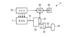
以下、図面を参照しながら、本発明の好ましい実施形態を詳細に説明する。図1に示すように、車両Vは、駆動源としての内燃機関(以下「エンジン」という)1と、駆動源及び発電機として機能する電動機(以下「モータ」という)61を有するハイブリッド車両であり、エンジン1及び/又はモータ61の駆動力を変速する変速機52を備えている。
Hereinafter, preferred embodiments of the present invention will be described in detail with reference to the drawings. As shown in FIG. 1, a vehicle V is a hybrid vehicle having an internal combustion engine (hereinafter referred to as “engine”) 1 as a drive source and an electric motor (hereinafter referred to as “motor”) 61 that functions as a drive source and a generator. A
モータ61は、パワードライブユニット(以下「PDU」という)62に接続され、PDU62は高圧バッテリ63に接続されている。モータ61を正の駆動トルクで駆動するとき、すなわち高圧バッテリ63から出力される電力でモータ61を駆動するときには、高圧バッテリ63から出力される電力は、PDU62を介してモータ61に供給される。また、モータ61を負の駆動トルクで駆動するとき、すなわちモータ61を回生動作させるときには、モータ61で発電される電力がPDU62を介して高圧バッテリ63に供給され、充電される。
The
PDU62は、電子制御ユニット(以下「ECU」という)20に接続されており、ECU20による制御の下、モータ61の動作を制御するとともに、高圧バッテリ63の充電及び放電を制御する。ECU20は、エンジン制御ECUとモータ制御ECU(いずれも図示せず)を通信バスによって接続することによって構成されている。
The
変速機52は、いわゆるデュアルクラッチ式のものであり、奇数段用クラッチ及び偶数段用クラッチ(いずれも図示せず)を介してエンジン1のクランク軸51に連結され、エンジン1から伝達された駆動力を奇数変速段又は偶数変速段によって変速する。変速された駆動力は、変速機52の出力軸53、差動ギヤ機構54及び駆動軸55を介して、駆動輪56に伝達され、それにより車両Vが駆動される。
The
以上の構成の車両Vの駆動装置は、その駆動モードとして、エンジン1のみを駆動源として車両Vを駆動するエンジン駆動モード(以下「ENGモード」という)と、変速機52の2つのクラッチを遮断した状態で、モータ61のみを駆動源として車両Vを駆動するモータ駆動モード(以下「EVモード」という)と、エンジン1及びモータ61の両方を駆動源として車両Vを駆動するハイブリッド駆動モード(以下「HEVモード」という)を有する。
The drive device for the vehicle V configured as described above has, as its drive mode, an engine drive mode (hereinafter referred to as “ENG mode”) that drives the vehicle V using only the
また、ENGモードでは、所定の自動停止条件が成立したときに、エンジン1を自動的に停止させる(以下「アイドルストップ」という)とともに、この自動停止状態から所定の再始動条件が成立したときに、エンジン1を自動的に再始動させるアイドルストップ制御が行われる。上記の自動停止条件は、車両Vの速度が所定速度以下であること、アクセルペダル(図示せず)が踏み込まれていないこと、ブレーキペダル(図示せず)が踏み込まれていること、高圧バッテリ63の残電荷量(SOC)が所定量以上であること、エンジン1の冷却水の温度が所定温度以上であって、エンジン1の暖機が完了していることなどの条件が、すべて満たされたときに成立する。
In the ENG mode, when a predetermined automatic stop condition is satisfied, the
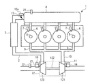
図2に示すように、エンジン1は、例えば直列の4つの気筒6を有するとともに、気筒6の燃焼室(図示せず)内に燃料を直接、噴射する直噴エンジンである。各気筒6には、燃料噴射弁7、点火プラグ8、吸気弁及び排気弁(いずれも図示せず)が設けられている。
As shown in FIG. 2, the
また、エンジン1は、吸気通路2、排気通路10、及び過給機としてのターボチャージャ12を備えている。吸気通路2はサージタンク4に接続され、サージタンク4は、吸気マニホルド5を介して各気筒6の燃焼室に接続されている。吸気通路2には、上流側から順に、ターボチャージャ12の後述するコンプレッサ123、ターボチャージャ12で加圧された空気を冷却するためのインタークーラ3、及びスロットル弁13が設けられている。スロットル弁13は、スロットル(TH)アクチュエータ13aによって駆動される。サージタンク4には、吸気圧PBを検出する吸気圧センサ21が設けられ、吸気通路2には、吸入空気流量GAIRを検出する吸入空気流量センサ22が設けられている。
The
ターボチャージャ12は、排気通路10に設けられ、排気の運転エネルギにより回転駆動されるタービン121と、吸気通路2に設けられ、シャフト122を介してタービン121に連結されたコンプレッサ123を備えている。コンプレッサ123は、エンジン1に吸入される空気(吸気)を加圧し、過給を行う。吸気通路2には、コンプレッサ123をバイパスするバイパス通路16が接続されており、バイパス通路16には、バイパス通路16を通過する空気の流量を調整するためのエアバイパス弁(以下「AB弁」という)17が設けられている。
The
排気通路10は、排気マニホルド9を介して各気筒6の燃焼室に接続されている。排気通路10には、タービン121をバイパスするバイパス通路11が接続されており、バイパス通路11の下流側の接続部には、バイパス通路11を通過する排気の流量を調整するためのウェイストゲート弁(以下「WG弁」という)14が設けられている。また、図示しないが、エンジン1には、燃焼室から排気通路10に排出された排気の一部を吸気通路2に還流させるための周知の排気還流(EGR)装置が設けられている。
The
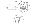
図3に示すように、WG弁14を駆動する駆動機構30は、アクチュエータとしてのモータ31、ロッド32、遮熱部材33、及びWG弁14の弁体15に連結されたリンク機構34を備えている。モータ31は例えばDCモータで構成されており、ECU20による制御の下、通電の向きに応じてモータ31の正転/逆転が切り替えられ、通電のための駆動パルスのデューティ比(以下「通電デューティ比」という)Idutyに応じて、モータ31のトルクが制御される。
As shown in FIG. 3, the
また、図示しないが、モータ31のロータには雌ねじが形成され、ロッド32にはこの雌ねじに螺合する雄ねじが形成されている。この構成により、モータ31の回転がロッド32の直進運動に変換され、ロッド32は、モータ31の回転方向に応じて図3の右方又は左方に移動する。
Although not shown, the rotor of the
リンク機構34は、遮熱部材33を介してロッド32に連結された連結部材34aと、連結部材34aに順にピン結合された第1リンク材34b及び第2リンク材34cを備えており、第2リンク材34cは、回転軸35に回転自在に支持されている。また、第2リンク材34cには保持部材36が一体に設けられ、この保持部材36にWG弁14の弁体15が一体に保持されている(図3(b)参照)。
The
図3(a)は、WG弁14の閉弁状態、すなわちWG弁14がバイパス通路11を閉鎖している状態を示す。この閉弁状態から、モータ31に所定の向きの電流が通電されると、それに応じてモータ31が所定の方向に回転駆動され、そのロータに螺合するロッド32が図3の矢印B方向に移動する。これに伴い、リンク機構34の第2リンク材34cとこれと一体の保持部材36及び弁体15が、回転軸35を中心として矢印C方向に回動することにより、WG弁14が開弁する。
FIG. 3A shows a closed state of the
この開弁状態から、モータ31に上記と逆向きの電流が通電されると、モータ31が逆方向に回転駆動され、ロッド32が矢印Bと反対方向に移動し、それに伴い、リンク機構34が上記と逆方向に動作し、第2リンク材34c、保持部材36及び弁体15が、矢印Cと反対方向に回動することにより、WG弁14は閉弁状態に復帰する。以下、上記のようにWG弁14を開弁側に駆動するときの通電デューティ比Idutyを「正」とし、WG弁14を閉弁側に駆動するときの通電デューティ比Idutyを「負」と定義する。
From this valve-opened state, when a current in the opposite direction to the
したがって、通電デューティ比Idutyが負の場合には、WG弁14が全閉位置に向かって駆動されるとともに、その絶対値が大きいほど、閉弁時に弁体15を弁座(図示せず)に押し付ける力はより大きくなる。また、モータ31のロータがロッド32に螺合しているため、通電デューティ比Idutyが0になり、モータ31の回転が停止されると、WG弁14は停止時の開度に保たれる。
Therefore, when the energization duty ratio Iduty is negative, the
また、ロッド32の弁体15と反対側の端部には、弁開度センサ23が設けられている。弁開度センサ23は、ロッド32の軸線方向(矢印B方向)の位置を検出することによって、WG弁14の開度(以下「検出開度」という)WGAを検出する。AB弁17の駆動機構(図示せず)も同様に構成されており、この駆動機構は、AB弁17を開閉駆動するためのモータや、AB弁17の開度を検出するための弁開度センサを備えている。
A
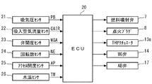
図4は、エンジン1の制御装置の構成を示す。ECU20には、前述した吸気圧センサ21、吸入空気流量センサ22及び弁開度センサ23の他、エンジン1の回転数(以下「エンジン回転数」という)NEを検出する回転数センサ24、車両Vのアクセルペダルの操作量(以下「アクセル開度」という)APを検出するアクセル開度センサ25や、エンジン1の冷却水の温度(以下「エンジン水温」という)TWを検出する水温センサ26などが接続されており、それらの検出信号が入力される。ECU20の出力側には、燃料噴射弁7、点火プラグ8、THアクチュエータ13a、WG弁14(モータ31)、及びAB弁17(モータ)が接続されている。
FIG. 4 shows the configuration of the control device of the
ECU20は、CPU、RAM、ROM及び入力インターフェース(いずれも図示せず)などから成るマイクロコンピュータで構成されており、上述した各種のセンサ21〜26の検出信号などに応じて、前述した車両Vの駆動モード(ENGモード、HEVモード又はEVモード)を決定するとともに、決定した駆動モードに応じてエンジン1及びモータ61を制御する。ENGモードでは、前述したアイドルストップ制御が実行される。
The
また、上記のエンジン制御として、ECU20は、エンジン1の運転状態(主としてエンジン回転数NE及び要求トルクTRQD)に応じて、燃料噴射弁7による燃料噴射制御、点火プラグ8による点火制御、スロットル弁13による吸入空気量制御、及びWG弁14による過給圧制御などを行う。要求トルクTRQDは、主としてアクセル開度APに応じ、アクセル開度APが増加するほど、より大きくなるように算出される。なお、実施形態では、ECU20が、目標開度設定手段、制御手段及び全閉位置学習手段に相当する。
Further, as the engine control described above, the
上記の過給圧制御では、エンジン1の運転状態などに応じて、WG弁14の目標開度WGCMDが設定されるとともに、弁開度センサ23で検出された開度が目標開度WGCMDに一致するように、モータ31の通電制御が行われる。このため、WG弁14の実際の開度を目標開度WGCMDに正確に一致させ、所望の過給圧を精度良く得るためには、弁開度センサ23で検出される開度の精度を高めることが必要である。
In the above supercharging pressure control, the target opening degree WGCMD of the
一方、弁開度センサ23は、前述したように、WG弁14の弁体15の開度を直接、検出するのではなく、駆動機構30を介して弁体15に連結されたロッド32の軸線方向の位置を介して、検出開度WGAを間接的に得るように構成されている。このため、弁開度センサ23で検出される検出開度WGAには、駆動機構30の構成部品の摩耗などによる経年的誤差や、駆動機構30の構成部品及びロッド32などの温度に依存する温度依存誤差などの、様々な要因による多くの種類の誤差が含まれる。
On the other hand, the
このような誤差をできるだけ排除するために、本実施形態では、WG弁14の全閉位置学習が適時に行われる。具体的には、弁体15が全閉位置に到達したときに弁開度センサ23で検出された検出開度WGAを全閉開度学習値WGFCとして学習し、記憶するとともに、その後に弁開度センサ23で検出された検出開度WGAから全閉開度学習値WGFCを減算した値を、そのときのWG弁14の開度(以下「弁開度」という)WGOとして算出する。後述するWG弁14の開度制御では、以上のように学習補正された弁開度WGOが用いられる。
In order to eliminate such an error as much as possible, in this embodiment, the fully closed position learning of the
なお、上記のWG弁14の全閉位置学習は、イグニッションスイッチがオンされた直後に低温時学習として実行され、エンジン1の運転中(ENGモード)に、WG弁14が全閉位置に制御されたタイミングにおいて運転時学習として実行される他、後述するように、エンジン1の停止状態(EVモード及びアイドルストップ中)において、停止時学習として実行される。
The above-described fully closed position learning of the
図5は、WG弁14の開度制御を実行する処理のフローチャートである。本処理は、ECU20において、所定時間ごとに繰り返し実行される。
FIG. 5 is a flowchart of a process for executing the opening degree control of the
本処理では、まずステップ1(「S1」と図示。以下同じ)において、ENGモードフラグF_ENGが「1」であるか否かを判別する。この答えがYESで、車両Vの現在の駆動モードがENGモードのときには、エンジン1が始動中であるか否かを判定する(ステップ2)。この判定では、エンジン1の始動動作の開始後、エンジン回転数NEが所定のアイドル回転数(立上がり回転数)に達していないときに、始動中であると判定される。
In this process, first, in step 1 (illustrated as “S1”, the same applies hereinafter), it is determined whether or not the ENG mode flag F_ENG is “1”. If the answer is YES and the current drive mode of the vehicle V is the ENG mode, it is determined whether or not the
このステップ2の答えがYESで、エンジン1が始動中のときには、WG弁14の目標開度WGCMDを0に設定する(ステップ3)とともに、モータ31の通電デューティ比Idutyを値0よりも若干小さい負の所定値IdSTR(例えば−5%)に設定し(ステップ4)、本処理を終了する。これにより、エンジン1の始動中、WG弁14は、その弁体15が弁座に比較的小さな力で押し付けられた状態で、閉弁位置に保持される。
When the answer to step 2 is YES and the
一方、エンジン1が始動中でないときには、ステップ5において、WG弁14の目標開度WGCMDを設定する。この目標開度WGCMDの設定は、エンジン1の運転状態、例えば要求トルクTRQD及びエンジン回転数NEに応じ、所定のマップ(図示せず)を検索することによって行われる。次に、設定した目標開度WGCMDが0であるか否かを判別し(ステップ6)、その答えがYESのときには、前記ステップ4を実行した後、本処理を終了する。このように、エンジン1の始動後の運転状態において、目標開度WGCMDが0に設定されているときには、通電デューティ比Idutyは、始動中と同様、所定値IdSTRに設定される。
On the other hand, when the
前記ステップ6の答えがNOで、目標開度WGCMDが0でないときには、前回の目標開度WGCMDZが0であるか否かを判別する(ステップ7)。この答えがYESのとき、すなわち今回の処理サイクルがWG弁14を全閉位置から開弁させる最初のタイミングに相当するときには、目標開度WGCMDが所定のしきい値WGREF以上であるか否かを判別する(ステップ8)。
If the answer to step 6 is NO and the target opening degree WGCMD is not 0, it is determined whether or not the previous target opening degree WGCMDZ is 0 (step 7). When this answer is YES, that is, when the current processing cycle corresponds to the first timing for opening the
この答えがYESで、目標開度WGCMDが比較的大きいときには、通電デューティ比Idutyを所定の正の最大値IdMAX(例えば100%)に設定し(ステップ9)、本処理を終了する。このように、WG弁14を全閉位置から比較的大きな目標開度WGCMDに向かって開弁するときには、通電デューティ比Idutyは、後述する通常のフィードバック制御によらず、フィードフォワード制御によって所定の最大値IdMAXに設定される。
If the answer is YES and the target opening degree WGCMD is relatively large, the energization duty ratio Iduty is set to a predetermined positive maximum value IdMAX (for example, 100%) (step 9), and this process is terminated. As described above, when the
前記ステップ8の答えがNOで、目標開度WGCMDが比較的小さいとき、又は前記ステップ7の答えがNOで、WG弁14を全閉位置から開弁させる最初のタイミングでないときには、ステップ10において通電デューティ比Idutyを算出し、本処理を終了する。この通電デューティ比Idutyの算出は、前述したようにして算出されたWG弁14の弁開度WGOが目標開度WGCMDになるようにフィードバック制御(例えばPID制御)によって、行われる。
If the answer to step 8 is NO and the target opening degree WGCMD is relatively small, or if the answer to step 7 is NO and it is not the first timing to open the
一方、前記ステップ1の答えがNOで、ENGモードでないときには、目標開度WGCMDを0に設定する(ステップ11)。次に、EVモードフラグF_EV又はアイドルストップフラグF_ISが「1」であるか否かを判別する(ステップ12)。この答えがNOで、車両Vの駆動モードがEVモードではなく、またアイドルストップ中でもないとき、例えばイグニッションスイッチをオフにした車両Vの停止状態のときには、通電デューティ比Idutyを0に設定し(ステップ13)、本処理を終了する。 On the other hand, when the answer to step 1 is NO and the engine is not in the ENG mode, the target opening degree WGCMD is set to 0 (step 11). Next, it is determined whether or not the EV mode flag F_EV or the idle stop flag F_IS is “1” (step 12). When the answer is NO and the drive mode of the vehicle V is not the EV mode and is not in the idling stop, for example, when the vehicle V is in a stop state with the ignition switch turned off, the energization duty ratio Iduty is set to 0 (step 13) The process is terminated.
上記ステップ12の答えがYESで、EVモード又はアイドルストップ中のときには、学習完了フラグF_LRNDNが「1」であるか否かを判別する(ステップ14)。後述するように、この学習完了フラグF_LRNDNは、EVモード又はアイドルストップ中に実行されるWG弁14の全閉位置学習が完了したときに「1」にセットされるものである。このステップ14の答えがNOで、全閉位置学習が完了していないときには、通電デューティ比Idutyを値0よりもかなり小さい(絶対値が大きい)負の学習用所定値IdLRN(例えば−50%)に設定する(ステップ15)。これにより、WG弁14は、弁体15が弁座に強く押し付けられた状態で、閉弁位置に確実に保持される。
If the answer to step 12 is YES and the EV mode or idling stop is being performed, it is determined whether or not a learning completion flag F_LRNDN is “1” (step 14). As will be described later, the learning completion flag F_LRNDN is set to “1” when the fully closed position learning of the
次に、上記のように通電デューティ比Idutyを学習用所定値IdLRNに設定した後、所定時間が経過したか否かを判別し(ステップ16)、経過していないときには、そのまま本処理を終了する。所定時間が経過したときには、WG弁14の閉弁位置を学習する(ステップ17)とともに、学習が完了したことを表すために、学習完了フラグF_LRNDNを「1」にセットし(ステップ18)、本処理を終了する。
Next, after the energization duty ratio Iduty is set to the predetermined value for learning IdLRN as described above, it is determined whether or not a predetermined time has elapsed (step 16). . When the predetermined time has elapsed, the valve closing position of the
上記ステップ18が実行された後には、前記ステップ14の答えがYESになり、その場合には、前記ステップ13に進み、通電デューティ比Idutyを0に設定する。以上のように、EVモード又はアイドルストップに移行したときには、通電デューティ比Idutyを学習用所定値IdLRNに設定することにより、WG弁14が全閉位置に強制的に駆動され、全閉位置の学習が行われるとともに、学習が完了した以降は、通電デューティ比Idutyが0に制御され、モータ31の通電が停止される。
After
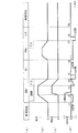
次に、図6を参照しながら、上述した図5のWG弁14の開度制御によって得られる動作例について説明する。図6(a)〜(d)にはそれぞれ、車両Vの駆動モードを含む運転状態、エンジン回転数NE、WG弁14の弁開度WGO、及び通電デューティ比Idutyの推移が示されている。
Next, an example of operation obtained by the above-described opening degree control of the
車両Vが停止した状態から、時刻t1においてイグニッションスイッチ及びスタータスイッチがオンされると、エンジン1の始動が開始され、ENGモードに移行する。この始動中には、目標開度WGCMDが0に設定される(図5のステップ3)とともに、通電デューティ比Idutyが負の所定値IdSTRに設定され(ステップ4)、弁開度WGOは全閉位置に維持される。その後、エンジン1の始動が終了するとともに、エンジン回転数NEの上昇に伴ってターボチャージャ12による過給が行われる。この場合、エンジン1の負荷が低く、目標開度WGCMDが0である限り(ステップ6:YES)、始動中と同様、通電デューティ比Idutyは所定値IdSTRに設定され、弁開度WGOは全閉位置に維持される(t1〜t2)。
When the ignition switch and the starter switch are turned on at the time t1 from the state where the vehicle V is stopped, the
時刻t2では、過給圧を低下させるために、WG弁14の開弁動作が開始される。この例では、設定された目標開度WGCMDが大きく、しきい値WGREF以上である(ステップ8:YES)ため、通電デューティ比Idutyは所定の最大値IdMAXに設定される(ステップ9)。その後の過給運転中及び時刻t3からのフューエルカット(F/C)運転中は、通電デューティ比Idutyは、弁開度WGOが目標開度WGCMDになるようにフィードバック制御によって算出される(t2〜t4)。
At time t2, in order to reduce the supercharging pressure, the valve opening operation of the
時刻t4においてEVモードに移行すると、目標開度WGCMDが0に設定される(ステップ11)とともに、その移行直後において、通電デューティ比Idutyを学習用所定値IdLRNに設定した(ステップ15)状態で、WG弁14の全閉位置学習が行われる(ステップ17)。時刻t5で全閉位置学習が完了すると、それ以降、通電デューティ比Idutyは0に設定され(ステップ13)、モータ31の通電が停止される(t5〜t6)。
When shifting to the EV mode at time t4, the target opening degree WGCMD is set to 0 (step 11), and immediately after the transition, the energization duty ratio Iduty is set to the learning predetermined value IdLRN (step 15). The fully closed position learning of the
その後、時刻t6においてEVモードからENGモードに移行する。このENGモードでは、その全体にわたって、目標開度WGCMDが0に設定され、WG弁14の開弁が行われないため、通電デューティ比Idutyは所定値IdSTRに設定され、弁開度WGOは全閉位置に維持される(t6〜t7)。
Thereafter, at time t6, the EV mode is shifted to the ENG mode. In this ENG mode, the target opening degree WGCMD is set to 0 over the whole, and the
時刻t7では、アイドルストップ(I/S)が開始される。このアイドルストップ中の動作は、EVモードと同じであり、その移行直後に、通電デューティ比Idutyを学習用所定値IdLRNに設定した状態で、WG弁14の全閉位置学習が行われ、その完了(t8)以降、通電デューティ比Idutyが0に設定され、モータ31の通電が停止される(t8〜t9)。その後、時刻t9においてイグニッションスイッチがオフされることで、車両Vが停止状態になり、それまでのWG弁14の全閉状態とモータ31の通電停止状態が維持される。
At time t7, idle stop (I / S) is started. The operation during the idle stop is the same as that in the EV mode. Immediately after the transition, the fully closed position learning of the
以上のように、本実施形態によれば、エンジン1の始動中又はWG弁14の目標開度WGCMDが0であるエンジン1の運転中には、モータ31の通電デューティ比Idutyが、値0よりも若干小さい負の所定値IdSTRに設定されることによって、WG弁14は、その弁体15が弁座に比較的小さな力で押し付けられた状態で、全閉位置に確実に保持される。これにより、始動中又は運転中のエンジン1の振動などの影響によって、WG弁14が振動することがなくなり、その弁体15の弁座との当接、及びそれに起因する雑音の発生や弁体15などの劣化を防止することができる。また、その状態から急加速が要求された場合に、過給圧を速やかに上昇させることができ、良好な加速応答性を確保することができる。また、通電デューティ比Idutyが値0に近い小さい値に設定されるので、消費電力を抑制することができる。
As described above, according to the present embodiment, during the start of the
また、エンジン1が停止されるEVモード又はアイドルストップ中においては、その移行直後にWG弁14を全閉位置に駆動した後、通電デューティ比Idutyを0に設定し、モータ31の通電を停止する通電停止制御が実行される。停止状態ではエンジン1が振動しないので、WG弁14の全閉位置への駆動後にモータ31の通電を停止しても、WG弁14は全閉位置に保持される。したがって、EVモード中及びアイドルストップ中においても、WG弁14の振動が防止され、弁体15の弁座との当接による雑音の発生及び弁体15などの劣化を防止できるとともに、その状態から急加速が要求された場合に、過給圧を速やかに上昇させ、良好な加速応答性を確保することができる。また、モータ31の通電が停止され、その間の消費電力は0になるので、上述したエンジン1の始動中などにおける消費電力の抑制とあいまって、消費電力を最小限に抑制することができる。
Further, during the EV mode in which the
また、EVモードの場合には特に、走行する車両Vの振動によってWG弁14が振動し、弁体15が弁座に当接する可能性がある一方、エンジン1が停止されていることで、当接による雑音が聞こえやすいため、商品性が低下しやすい。実施形態では、EVモードにおいて上記の通電停止制御が実行されることによって、弁体15の当接による雑音の発生が防止されるので、上記の不具合を有効に回避し、商品性を向上させることができる。また、モータ31の通電が停止されることにより、EVモードにおいて特に問題とされる電磁波ノイズの発生を有効に防止することができる。
Further, particularly in the EV mode, the
また、EVモード及びアイドルストップ中において、WG弁14が全閉位置に駆動された後に、WG弁14の全閉位置学習が行われるので、その学習頻度を高めることができる。また、エンジン1の停止状態から急加速が要求された場合に、直前に学習された全閉位置を用いてウェイストゲート弁の開度制御を行うことができ、過給圧の制御を精度良く行うことができる。
Further, during the EV mode and idling stop, after the
また、WG弁14の全閉位置からの開弁動作の開始直後には、フィードフォワード制御により、通電デューティ比Idutyが最大値IdMAXに制御される。これにより、フィードバック制御を行った場合の応答遅れがなくなり、WG弁14がより速やかに開弁側に駆動され、開弁時間が短縮される。その結果、上昇した過給圧がより速やかに低下し、上限値を上回る過給圧のオーバーシュートが生じにくくなるので、その分、より大きな過給圧を目標とすることが可能になり、エンジン1の出力を高めることができる。また、このフィードフォワード制御を、目標開度WGCMDがしきい値WGREF以上であるときに実行するので、WG弁14の開弁動作が高い応答性で要求される場合を対象として、上記の効果を有効に得ることができる。
Further, immediately after the start of the valve opening operation from the fully closed position of the
なお、本発明は、説明した実施形態に限定されることなく、種々の態様で実施することができる。例えば、実施形態では、WG弁14を駆動する駆動機構30が、アクチュエータとしてのモータ31や、モータ31の回転をロッド32の直進運動に変換する機構、ロッド32の往復動に従って弁体15を開閉するリンク機構34などで構成されているが、駆動機構の基本構成及び細部の構成は、ウェイストゲート弁を電気的に駆動するものである限り、任意である。例えば、アクチュエータとして、実施形態の回転型モータに代えて、直動型モータや電磁アクチュエータなどを用いてもよい。
In addition, this invention can be implemented in various aspects, without being limited to the described embodiment. For example, in the embodiment, the
また、実施形態では、WG弁14を全閉位置から開弁する際に通電デューティ比Idutyを最大値IdMAXに設定するフィードフォワード制御を、開弁動作の開始時に1回のみ行っているが、これを複数回、行ってもよいことはもちろんである。
In the embodiment, the feedforward control for setting the energization duty ratio Iduty to the maximum value IdMAX when the
さらに、実施形態は、ハイブリッド車両に電動機とともに搭載されたエンジンの例であるが、本発明は、これに限らず、電動機を有しない車両用のエンジンに適用してもよく、また、車両用以外のエンジン、例えば、クランク軸を鉛直に配置した船外機などのような船舶推進機用エンジンにも適用可能である。その他、本発明の趣旨の範囲内で、細部の構成を適宜、変更することが可能である。 Furthermore, the embodiment is an example of an engine mounted on a hybrid vehicle together with an electric motor. However, the present invention is not limited to this, and may be applied to an engine for a vehicle that does not have an electric motor. The present invention is also applicable to a marine propulsion engine such as an outboard motor having a crankshaft arranged vertically. In addition, it is possible to appropriately change the detailed configuration within the scope of the gist of the present invention.
1 エンジン(内燃機関)
11 バイパス通路
12 ターボチャージャ(過給機)
121 タービン
14 WG弁(ウェイストゲート弁)
20 ECU(目標開度設定手段、制御手段、全閉位置学習手段)
23 弁開度センサ(実開度検出手段)
31 モータ(アクチュエータ)
61 モータ(電動機)
WGCMD 目標開度(ウェイストゲート弁の目標開度)
WGO WG開度(ウェイストゲート弁の開度)
Iduty 通電デューティ比(アクチュエータの通電量)
IdSTR 所定値(所定の通電量)
V 車両
IdMAX 最大値(通電量の所定の最大値)
1 engine (internal combustion engine)
121
20 ECU (target opening setting means, control means, fully closed position learning means)
23 Valve opening sensor (actual opening detection means)
31 Motor (actuator)
61 Motor (electric motor)
WGCMD target opening (target opening of waste gate valve)
WGO WG opening (Wastegate valve opening)
Iduty Energization duty ratio (actuator energization amount)
IdSTR predetermined value (predetermined energization amount)
V Vehicle IdMAX maximum value (predetermined maximum value of energization amount)
Claims (4)
前記ウェイストゲート弁を駆動する電動のアクチュエータと、
要求トルクを含む前記内燃機関の運転状態に応じて、前記ウェイストゲート弁の目標開度を設定する目標開度設定手段と、
当該アクチュエータの通電を制御することによって、前記ウェイストゲート弁の開度を制御する制御手段と、を備え、
当該制御手段は、前記内燃機関の始動中又は前記目標開度が全閉開度に設定された運転状態では、前記アクチュエータの通電量を前記ウェイストゲート弁を全閉位置に押付け可能な所定の通電量に制御し、前記内燃機関の所定の停止状態では、前記ウェイストゲート弁を全閉位置に駆動した後に前記アクチュエータの通電を停止する通電停止制御を実行し、
前記ウェイストゲート弁の実際の開度を検出する実開度検出手段をさらに備え、
前記制御手段は、前記検出された実開度が前記目標開度になるようにフィードバック制御によって前記アクチュエータの通電量を制御するとともに、前記目標開度の変更に応じた前記ウェイストゲート弁の全閉位置からの開弁動作の開始直後には、前記フィードバック制御に代えてフィードフォワード制御により、前記アクチュエータの通電量を前記ウェイストゲート弁を開弁する側の所定の最大値に制御することを特徴とする内燃機関の制御装置。 A control apparatus for an internal combustion engine, comprising: a supercharger that supercharges intake air; and a wastegate valve that is provided in a bypass passage that bypasses a turbine of the supercharger and adjusts a supercharging pressure by the supercharger. There,
An electric actuator for driving the wastegate valve;
Wherein according to the operating state of the internal combustion engine, including a required torque, and the target opening setting means for setting a target opening of the waste gate valve,
Control means for controlling the opening of the waste gate valve by controlling energization of the actuator,
The control means is a predetermined energization capable of pressing the amount of energization of the actuator to the fully closed position during start-up of the internal combustion engine or the operation state in which the target opening is set to a fully closed opening. And when the internal combustion engine is in a predetermined stop state, an energization stop control is performed to stop energization of the actuator after driving the wastegate valve to a fully closed position ,
An actual opening detecting means for detecting an actual opening of the wastegate valve;
The control means controls the energization amount of the actuator by feedback control so that the detected actual opening becomes the target opening, and fully closes the waste gate valve according to the change of the target opening. Immediately after the start of the valve opening operation from the position, the energization amount of the actuator is controlled to a predetermined maximum value on the side of opening the waste gate valve by feedforward control instead of the feedback control. A control device for an internal combustion engine.
前記内燃機関の所定の停止状態は、前記電動機駆動モードにおける停止状態であることを特徴とする、請求項1又は2に記載の内燃機関の制御装置。 The internal combustion engine is mounted on a vehicle together with an electric motor as a drive source, and the vehicle has an electric motor drive mode in which the internal combustion engine is stopped and only the electric motor is a drive source,
The control apparatus for an internal combustion engine according to claim 1 or 2 , wherein the predetermined stop state of the internal combustion engine is a stop state in the electric motor drive mode .
Priority Applications (3)
| Application Number | Priority Date | Filing Date | Title |
|---|---|---|---|
| JP2016226938A JP6461069B2 (en) | 2016-11-22 | 2016-11-22 | Control device for internal combustion engine |
| CN201710967792.3A CN108087107B (en) | 2016-11-22 | 2017-10-17 | Control device for internal combustion engine |
| US15/796,862 US20180142613A1 (en) | 2016-11-22 | 2017-10-30 | Control device for an internal combustion engine |
Applications Claiming Priority (1)
| Application Number | Priority Date | Filing Date | Title |
|---|---|---|---|
| JP2016226938A JP6461069B2 (en) | 2016-11-22 | 2016-11-22 | Control device for internal combustion engine |
Publications (2)
| Publication Number | Publication Date |
|---|---|
| JP2018084176A JP2018084176A (en) | 2018-05-31 |
| JP6461069B2 true JP6461069B2 (en) | 2019-01-30 |
Family
ID=62144855
Family Applications (1)
| Application Number | Title | Priority Date | Filing Date |
|---|---|---|---|
| JP2016226938A Expired - Fee Related JP6461069B2 (en) | 2016-11-22 | 2016-11-22 | Control device for internal combustion engine |
Country Status (3)
| Country | Link |
|---|---|
| US (1) | US20180142613A1 (en) |
| JP (1) | JP6461069B2 (en) |
| CN (1) | CN108087107B (en) |
Families Citing this family (6)
| Publication number | Priority date | Publication date | Assignee | Title |
|---|---|---|---|---|
| JP7196715B2 (en) * | 2019-03-25 | 2022-12-27 | トヨタ自動車株式会社 | Hybrid vehicle and hybrid vehicle control method |
| JP7183928B2 (en) * | 2019-04-10 | 2022-12-06 | トヨタ自動車株式会社 | vehicle |
| US11459966B2 (en) * | 2019-12-20 | 2022-10-04 | Pratt & Whitney Canada Corp. | Systems and methods for operating an on-off valve |
| JP7512905B2 (en) * | 2021-01-08 | 2024-07-09 | トヨタ自動車株式会社 | Engine equipment |
| JP7782149B2 (en) * | 2021-05-31 | 2025-12-09 | マツダ株式会社 | Control device for turbocharged engine |
| CN114435338A (en) * | 2022-03-01 | 2022-05-06 | 一汽解放汽车有限公司 | Vehicle power system control method, device, computer equipment and storage medium |
Family Cites Families (14)
| Publication number | Priority date | Publication date | Assignee | Title |
|---|---|---|---|---|
| JP2008222033A (en) * | 2007-03-13 | 2008-09-25 | Toyota Motor Corp | Control device for internal combustion engine |
| JP5454437B2 (en) * | 2010-09-24 | 2014-03-26 | トヨタ自動車株式会社 | Wastegate valve device |
| US8820297B2 (en) * | 2011-05-12 | 2014-09-02 | Toyota Jidosha Kabushiki Kaisha | Control device for internal combustion engine |
| US20150040561A1 (en) * | 2012-03-30 | 2015-02-12 | Toyota Jidosha Kabushiki Kaisha | Control device for internal combustion engine |
| JP6132092B2 (en) * | 2013-05-23 | 2017-05-24 | 三菱自動車工業株式会社 | Engine control device |
| JP6160816B2 (en) * | 2013-05-23 | 2017-07-12 | 三菱自動車工業株式会社 | Engine control device |
| JP6079513B2 (en) * | 2013-09-04 | 2017-02-15 | トヨタ自動車株式会社 | Waste gate valve controller |
| JP5847857B2 (en) * | 2014-01-14 | 2016-01-27 | 本田技研工業株式会社 | Reference position learning device for a valve of an internal combustion engine |
| JP6295725B2 (en) * | 2014-02-28 | 2018-03-20 | トヨタ自動車株式会社 | Turbocharger abnormality determination device |
| JP6123707B2 (en) * | 2014-03-04 | 2017-05-10 | 株式会社デンソー | Control device for internal combustion engine |
| JP6237654B2 (en) * | 2015-01-14 | 2017-11-29 | トヨタ自動車株式会社 | Control device for internal combustion engine |
| JP2016142192A (en) * | 2015-02-03 | 2016-08-08 | 株式会社デンソー | Intake / exhaust device for internal combustion engine |
| JP6380446B2 (en) * | 2016-03-30 | 2018-08-29 | トヨタ自動車株式会社 | Vehicle control device |
| JP6173523B1 (en) * | 2016-04-26 | 2017-08-02 | 三菱電機株式会社 | Control device for internal combustion engine |
-
2016
- 2016-11-22 JP JP2016226938A patent/JP6461069B2/en not_active Expired - Fee Related
-
2017
- 2017-10-17 CN CN201710967792.3A patent/CN108087107B/en not_active Expired - Fee Related
- 2017-10-30 US US15/796,862 patent/US20180142613A1/en not_active Abandoned
Also Published As
| Publication number | Publication date |
|---|---|
| US20180142613A1 (en) | 2018-05-24 |
| CN108087107B (en) | 2021-01-26 |
| JP2018084176A (en) | 2018-05-31 |
| CN108087107A (en) | 2018-05-29 |
Similar Documents
| Publication | Publication Date | Title |
|---|---|---|
| JP6461069B2 (en) | Control device for internal combustion engine | |
| US9856829B2 (en) | System and methods for improving fuel economy | |
| US7532973B2 (en) | Control apparatus of direct injection internal combustion engine | |
| JP5847857B2 (en) | Reference position learning device for a valve of an internal combustion engine | |
| CN110067642A (en) | System and method for pressurization control | |
| US10975790B2 (en) | Systems and methods for controlling boost during an engine cold start | |
| US10823092B2 (en) | System and method for waste-gate valve diagnostics | |
| US10415460B2 (en) | Control device for an internal combustion engine | |
| US10077728B1 (en) | Engine pump loss control to improve battery system charging and overall vehicle efficiency | |
| JP2008151064A (en) | Control device for internal combustion engine | |
| JP6505073B2 (en) | Control device for internal combustion engine | |
| JP2004324440A (en) | Diesel engine control unit | |
| US12194983B2 (en) | Hybrid electric vehicle propulsion start control | |
| US10502123B2 (en) | Control device for vehicle, and control method for vehicle | |
| JP6505071B2 (en) | Fully closed position learning device for waste gate valve | |
| JP7666110B2 (en) | Hybrid vehicle control device | |
| JP7026217B2 (en) | Control device and control method | |
| JP2012136980A (en) | Engine rotation stop control device | |
| JP6877935B2 (en) | Engine control unit | |
| JP6232890B2 (en) | Control device for internal combustion engine | |
| JP2019132185A (en) | Controller of internal combustion engine | |
| JP4998212B2 (en) | Control device for internal combustion engine | |
| WO2025154203A1 (en) | Method and device for controlling negative-pressure-generation valve of internal combustion engine | |
| JP2014238076A (en) | Vehicle |
Legal Events
| Date | Code | Title | Description |
|---|---|---|---|
| A977 | Report on retrieval |
Free format text: JAPANESE INTERMEDIATE CODE: A971007 Effective date: 20180712 |
|
| A131 | Notification of reasons for refusal |
Free format text: JAPANESE INTERMEDIATE CODE: A131 Effective date: 20180724 |
|
| A521 | Request for written amendment filed |
Free format text: JAPANESE INTERMEDIATE CODE: A523 Effective date: 20180920 |
|
| TRDD | Decision of grant or rejection written | ||
| A01 | Written decision to grant a patent or to grant a registration (utility model) |
Free format text: JAPANESE INTERMEDIATE CODE: A01 Effective date: 20181204 |
|
| A61 | First payment of annual fees (during grant procedure) |
Free format text: JAPANESE INTERMEDIATE CODE: A61 Effective date: 20181225 |
|
| R150 | Certificate of patent or registration of utility model |
Ref document number: 6461069 Country of ref document: JP Free format text: JAPANESE INTERMEDIATE CODE: R150 |
|
| LAPS | Cancellation because of no payment of annual fees |