JP6460880B2 - Game machine - Google Patents

Game machine Download PDF

Info

Publication number
JP6460880B2
JP6460880B2 JP2015069664A JP2015069664A JP6460880B2 JP 6460880 B2 JP6460880 B2 JP 6460880B2 JP 2015069664 A JP2015069664 A JP 2015069664A JP 2015069664 A JP2015069664 A JP 2015069664A JP 6460880 B2 JP6460880 B2 JP 6460880B2
Authority
JP
Japan
Prior art keywords
display
unit
gaming machine
lid
sliding
Prior art date
Legal status (The legal status is an assumption and is not a legal conclusion. Google has not performed a legal analysis and makes no representation as to the accuracy of the status listed.)
Active
Application number
JP2015069664A
Other languages
Japanese (ja)
Other versions
JP2016187524A (en
JP2016187524A5 (en
Inventor
市原 高明
高明 市原
拓也 青柳
拓也 青柳
亜弥 附柴
亜弥 附柴
有希 杉本
有希 杉本
鉦一郎 江口
鉦一郎 江口
Current Assignee (The listed assignees may be inaccurate. Google has not performed a legal analysis and makes no representation or warranty as to the accuracy of the list.)
Daiichi Co Ltd
Original Assignee
Daiichi Shokai Co Ltd
Priority date (The priority date is an assumption and is not a legal conclusion. Google has not performed a legal analysis and makes no representation as to the accuracy of the date listed.)
Filing date
Publication date
Application filed by Daiichi Shokai Co Ltd filed Critical Daiichi Shokai Co Ltd
Priority to JP2015069664A priority Critical patent/JP6460880B2/en
Publication of JP2016187524A publication Critical patent/JP2016187524A/en
Publication of JP2016187524A5 publication Critical patent/JP2016187524A5/ja
Application granted granted Critical
Publication of JP6460880B2 publication Critical patent/JP6460880B2/en
Active legal-status Critical Current
Anticipated expiration legal-status Critical

Links

Images

Landscapes

  • Pinball Game Machines (AREA)

Description

本発明は、パチンコ機やスロットマシン等の遊技機に関する。   The present invention relates to gaming machines such as pachinko machines and slot machines.

特許文献1に記載された従来の遊技機100は、図12に示したように、四角い枠状の外枠101と、その外枠101の前面に片開きの扉状に回動可能に取り付けられた前枠102と、その前枠102の前面上半部に開閉自在に取り付けられたガラス扉103と、同じく前枠102の前面下半部に開閉自在に取り付けられた前面扉104と、前記ガラス扉103と前面扉104の前面右端に遊技者側に向けて突き出し看板状に突設された右辺ユニット105と、ガラス扉103の前面上端に突設された上辺ユニット106と、を備えている。
かかる遊技機100の前記右辺ユニット105は、全体の大部分を占める表示部本体107と、その表示部本体107の上部に設けた蓋部108とから概略形成されている。
この右辺ユニット105の前記表示部本体107は、前後の幅に比べて左右の幅が格段に小さいスリムな箱状であって、透光性樹脂材料による表示シートを納めるシート受部を備えると共に、上面に前記シート受部に通じる差込み口109が開設されており、該差込み口109からシート受部に表示シートを差し込み得る。
一方、前記蓋部108は、表示部本体107の差込み口109を塞ぐものであり、表示部本体107の遊技者側の端部に回動自在に軸着されている。
そして、前記表示シートには、例えば遊技機100や遊技内容に関連する情報(機種名、遊技内容に関連するキャラクター等)が描かれており、シート受部に収められたセット状態で、その内容が右辺ユニット105の左右両面又はその何れかの面から視認し得るようになっている。
As shown in FIG. 12, a conventional gaming machine 100 described in Patent Document 1 is attached to a rectangular frame-like outer frame 101 and a front door of the outer frame 101 so as to be rotatable like a single-open door. The front frame 102, the glass door 103 attached to the upper half of the front face of the front frame 102 so as to be freely opened and closed, the front door 104 similarly attached to the lower half of the front face of the front frame 102 so as to be openable and closable, and the glass A right side unit 105 protruding toward the player side at the front right end of the door 103 and the front door 104 and protruding like a signboard, and an upper side unit 106 protruding from the upper front end of the glass door 103 are provided.
The right side unit 105 of the gaming machine 100 is roughly formed from a display unit body 107 occupying most of the whole and a lid unit 108 provided on the upper part of the display unit body 107.
The display unit main body 107 of the right side unit 105 has a slim box shape in which the left and right widths are significantly smaller than the front and rear widths, and includes a sheet receiving unit that stores a display sheet made of a translucent resin material. An insertion port 109 leading to the sheet receiving portion is formed on the upper surface, and a display sheet can be inserted into the sheet receiving portion from the insertion port 109.
On the other hand, the lid part 108 closes the insertion port 109 of the display part main body 107 and is pivotally attached to an end of the display part main body 107 on the player side.
For example, information relating to the gaming machine 100 and game contents (model name, characters related to game contents, etc.) is drawn on the display sheet, and the contents are displayed in a set state stored in the sheet receiving unit. Can be viewed from both the left and right sides of the right side unit 105 or from either side thereof.

特開2013−220208号公報JP2013-220208A

しかしながら、従来のような構成では、遊技機前面に突出する装飾が、他の部材と干渉したり従業員と接触するおそれがある場合に、遊技機に対する作業を効率よく行うことができない可能性ある。
However, in such structure as traditional, decorative projecting gaming machine front, when there is a risk of contact with the interference with other members or employees, it is performed efficiently work on the gaming machine there is a possibility that can not be.

本発明は、上記に鑑みなされたもので、その目的は、前面側に突出する装飾を備えつつ遊技機に対する作業の効率性を高めることにある。
The present invention has been made in view of the above, and its object is the efficiency of work on the gaming machine to the high Mel possible while providing a decorative projecting to the front side.

上記の目的を達成するため本発明は、
遊技機の前面側を構成する前扉と、
前記前扉の所定位置に位置する固定状態と、前記前扉の前記所定位置に位置しない非固定状態とに変化可能であり、前記固定状態にあるときに当該遊技機の装飾の一部を担う特定部材と、を備え、
前記特定部材は、所定の解除部が操作されることで非固定状態に変化し、該非固定状態では所定の摺動部に沿って摺動可能であり、該摺動を経て当該遊技機から離脱しうるものであって、
前記摺動部は、当該遊技機の前後方向に延びたレールであり、
前記特定部材は、前記摺動によって前記前扉から離れる方向に移動した後、離脱しうるようになっており、
前記特定部材が離脱するときには、前記特定部材の姿勢が前記固定状態にあるときと異なった姿勢になるように構成されてなる遊技機を提供する。
In order to achieve the above object, the present invention
A front door constituting the front side of the gaming machine,
It is possible to change between a fixed state where the front door is located at a predetermined position and an unfixed state where the front door is not located at the predetermined position, and bears part of the decoration of the gaming machine when in the fixed state. A specific member,
The specific member changes to a non-fixed state when a predetermined release portion is operated, and can slide along the predetermined sliding portion in the non-fixed state, and is detached from the gaming machine through the sliding. It can be
The sliding portion is a rail extending in the front-rear direction of the gaming machine,
The specific member can be detached after moving in a direction away from the front door by the sliding,
There is provided a gaming machine configured such that when the specific member is detached, the posture of the specific member is different from that in the fixed state .

本発明の遊技機によれば、前面側に突出する装飾を備えつつ必要な作業の効率性を高める効果がある。 According to the gaming machine of the present invention, there is efficiency enhanced Cormorants Ru effect of work required while providing a decorative projecting to the front side.

遊技機の正面図である。It is a front view of a gaming machine. 遊技機の前面部の斜視図である。It is a perspective view of the front part of a game machine. 遊技機の前面部の側面図である。It is a side view of the front part of a gaming machine. 表示部を示す縦断側面図である。It is a vertical side view which shows a display part. 表示部の反射凹部を省略した状態を示す縦断側面図である。It is a vertical side view which shows the state which abbreviate | omitted the reflective recessed part of the display part. 図4AのZ部の拡大図である。It is an enlarged view of the Z section of Drawing 4A. 表示部を示す縦断正面図である。It is a vertical front view which shows a display part. 蓋部の後面側から見た斜視図である。It is the perspective view seen from the rear surface side of the cover part. 蓋部を開位置に移動させた状態を示す表示部の斜視図である。It is a perspective view of the display part which shows the state which moved the cover part to the open position. 蓋部を開位置に移動させた状態を示す表示部の側面図である。It is a side view of the display part which shows the state which moved the cover part to the open position. 蓋部を開位置に移動させた状態を示す表示部の縦断正面図である。It is a vertical front view of the display part which shows the state which moved the cover part to the open position. (a)は光拡散板の一部拡大側面図、(b)は図10(a)のA−A線断面図である。(A) is a partially expanded side view of a light diffusing plate, (b) is the sectional view on the AA line of Fig.10 (a). (a)は左側部用表示シートの表示内容を省略した表面図、(b)は右側部用表示シートの表示内容を省略した表面図である。(A) is the surface figure which abbreviate | omitted the display content of the left side display sheet, (b) is the surface figure which abbreviate | omitted the display content of the right side display sheet. 従来の遊技機を示す斜視図である。It is a perspective view which shows the conventional game machine.

以下に本発明の実施の形態をパチンコ機を例に図面を参照しつつ説明する。
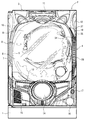
パチンコ機Pは、四角い枠状の外枠1と、その外枠1の前面に片開きの扉状に回動可能に取り付けられた本体部2(特許文献1の「前枠」相当)と、その本体部2の前面に開閉自在に取り付けられた前面部3(特許文献1の「ガラス扉」と「前面扉」に相当)と、該前面部3の前面右端に遊技者側に向けて突き出し看板状に突設された表示部4(特許文献1の「右辺ユニット」に相当)と、を備えている。
Embodiments of the present invention will be described below with reference to the drawings, taking a pachinko machine as an example.
The pachinko machine P includes a square frame-shaped outer frame 1 and a main body 2 (corresponding to the “front frame” in Patent Document 1) attached to the front surface of the outer frame 1 so as to be rotatable like a single-open door, A front surface portion 3 (corresponding to “glass door” and “front door” in Patent Document 1) attached to the front surface of the main body portion 2 so as to be freely opened and closed, and protrudes toward the player side at the right front end of the front surface portion 3 And a display unit 4 (corresponding to the “right side unit” in Patent Document 1) projecting in a sign shape.

[外枠]
前記外枠1は、木製又は合成樹脂製であって四角く枠組みされており、遊技場の島設備に取り付けられる。
[Outer frame]
The outer frame 1 is made of wooden or synthetic resin and has a rectangular frame, and is attached to an island facility of a game arcade.

[本体部]
前記本体部2は、外枠1の前面に片開きの扉状に回動可能に取り付けられており、図1に示したように、ガイドレール5で略円形に囲われた遊技領域6を有する遊技盤7がその前面に着脱自在に装着され、さらに、図示しないが、画像表示装置や演出装置等を制御する制御基板、前記遊技領域6に遊技媒体たるパチンコ球を打ち込む打球発射装置、パチンコ球を入賞の景品として放出するための景品球放出手段等を備えている。なお、景品球放出手段は、周知のように本体部2の後面側に設けられており、上から順に、パチンコ球を溜める球タンク、その球タンクに連結された導出樋、その導出樋の終端に連結された景品球放出装置、その景品球放出装置に連結された排出樋、等からなる。
[Main unit]
The main body 2 is attached to the front surface of the outer frame 1 so as to be rotatable like a single-open door, and has a game area 6 surrounded by a guide rail 5 in a substantially circular shape as shown in FIG. A game board 7 is detachably mounted on the front surface of the game board 7, and although not shown, a control board for controlling an image display device, an effect device, etc., a batting ball launcher for driving a pachinko ball as a game medium into the game area 6, and a pachinko ball Is provided with a prize ball emitting means for releasing the prize as a prize for winning. As is well known, the prize ball discharge means is provided on the rear surface side of the main body 2, and in order from the top, the ball tank for storing the pachinko balls, the lead rod connected to the ball tank, and the terminal end of the lead rod A prize ball emitting device connected to the prize ball, a discharge basket connected to the prize ball emitting device, and the like.

[前面部]
前記前面部3は、本体部2と同じく外枠1に対して片開きの扉状に取り付けられており、該本体部2の前面を覆う閉状態と、本体部2の前面を露出させる開状態とに回動し得る。
前面部3は、遊技盤7の遊技領域6に対応する位置にガラスや合成樹脂等の透明板8で覆われた窓部9を有しており、該窓部9を介して遊技盤7の遊技領域6が見える。前面部3には、かかる窓部9の上部と両横の三方を囲うように、照明等を備えた左辺装飾部10と上辺装飾部11と右辺装飾部12が設けられている。
[Front section]
The front surface portion 3 is attached to the outer frame 1 in the same manner as the main body portion 2 in a single-open door shape, and is in a closed state that covers the front surface of the main body portion 2 and an open state that exposes the front surface of the main body portion 2. And can be rotated.
The front surface portion 3 has a window portion 9 covered with a transparent plate 8 such as glass or synthetic resin at a position corresponding to the game area 6 of the game board 7. The game area 6 is visible. The front surface portion 3 is provided with a left side decorative portion 10, an upper side decorative portion 11, and a right side decorative portion 12 that are provided with illumination or the like so as to surround the upper portion of the window portion 9 and the three sides on both sides.

前面部3の窓部9より下側には、図1〜図3に示したように、前記景品球放出手段で放出されるパチンコ球を受け入れる上の球皿13と、該球皿13の前面から前面部3の下辺に至る領域を占有するように遊技者用の入力操作部(ボタンスイッチ)14が設けられ、また、その入力操作部14を挟んで正面向かって左半部に前記上の球皿13からオーバーフローするパチンコ球を受け入れる下の球皿15が設けられ、反対の右半部にパチンコ球の打球強さを調節するための打力調節装置(操作ハンドル)16が設けられている。
なお、このように上の球皿13の前面から前面部3の下辺に至る領域を占有するように入力操作部14を設けると共にその両隣に、オーバーフローするパチンコ球を受け入れる下の球皿15と打力調節装置16をそれぞれ配置することにより、入力操作部14を最大限に大きく且つ操作可能範囲を下方にまで拡大することができるため、腕の上げ下げが難儀になりつつある高齢の遊技者にも無理なく入力操作を行わせることができる。
また、前面部3には、前記閉状態にロックする錠装置17が設けられていて、専用の鍵で解錠して開き、閉じると自動的に施錠されるようになっている。
As shown in FIGS. 1 to 3, on the lower side of the window portion 9 of the front surface portion 3, there is an upper ball tray 13 that receives the pachinko balls released by the premium ball discharge means, and the front surface of the ball tray 13. A player input operation unit (button switch) 14 is provided so as to occupy a region extending from the front side to the lower side of the front unit 3, and the upper half of the input operation unit 14 is placed on the left half of the front side across the input operation unit 14. A lower ball tray 15 for receiving a pachinko ball overflowing from the ball tray 13 is provided, and a hitting force adjusting device (operation handle) 16 for adjusting the hitting strength of the pachinko ball is provided on the opposite right half. .
In addition, the input operation unit 14 is provided so as to occupy the region from the front surface of the upper ball tray 13 to the lower side of the front surface portion 3, and the lower ball tray 15 that receives the overflowing pachinko ball is placed on both sides thereof. By arranging the force adjusting devices 16 respectively, the input operation unit 14 can be enlarged to the maximum and the operable range can be expanded downward, so that even older players who are becoming difficult to raise and lower their arms Input operation can be performed without difficulty.
Further, the front surface portion 3 is provided with a locking device 17 that locks in the closed state. The locking device 17 is unlocked and opened with a dedicated key, and is automatically locked when closed.

[表示部]
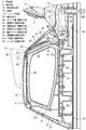
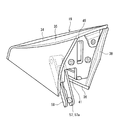
前記表示部4は、図2の斜視図に示したように、前面部3の前記右辺装飾部12を取り付けベースとして該右辺装飾部12から遊技者側に向けて突き出し看板状に突設されており、全体の大部分を占める表示部本体18と、その表示部本体18の上部に被せた蓋部19とから概略構成されている。
[Display section]
As shown in the perspective view of FIG. 2, the display unit 4 protrudes from the right side decoration unit 12 toward the player side with the right side decoration unit 12 of the front surface unit 3 as a mounting base, and is projected in a signboard shape. The display unit body 18 occupies most of the whole, and a cover unit 19 that covers the upper part of the display unit body 18.

[表示部本体]
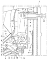
前記表示部本体18は、側面形状が、下底(台形の底辺)を垂直方向に向けた横向き略台形であって、上面に遊技者側に向けて下る勾配の傾斜が設けられている。該表示部本体18は、前後の幅(奥行き)に比べて左右の幅(厚み)が格段に小さいスリムな箱状であって、遊技者側から見た左側部18Lと右側部18Rのそれぞれに、図4A、図4Bに示したように、後述する表示シート20L,20Rを収めるシート受部21L,21Rが内向きのリブ22,22によって形成され、また、傾斜した前記上面に該シート受部21L,21Rに通じる差込み口23,23が開設されている。左右のシート受部21L,21Rは、図4A、図5、図10に示したように、左側部18Lと右側部18Rの間に設けられた透明な合成樹脂製の光拡散板24により仕切られており、したがって前記差込み口23,23も左右に分かれている。
また、表示部本体18の前記左側部18Lと右側部18Rのそれぞれには前記シート受部21L,21Rに対応する透明な表示窓25,25が形成されており、該表示窓25,25を介して前記シート受部21L,21Rの内部が外部から見えるようになっている。
[Display unit]
The display unit main body 18 has a side surface shape that is substantially trapezoidal in a horizontal direction with the bottom (trapezoidal base) oriented in the vertical direction, and is provided with a slope on the upper surface that is inclined downward toward the player. The display unit body 18 has a slim box shape in which the left and right widths (thicknesses) are much smaller than the front and rear widths (depths). The display unit body 18 has a left side 18L and a right side 18R as viewed from the player side. 4A and 4B, sheet receiving portions 21L and 21R for accommodating display sheets 20L and 20R, which will be described later, are formed by inward ribs 22 and 22, and the sheet receiving portion is formed on the inclined upper surface. The insertion ports 23 and 23 leading to 21L and 21R are established. As shown in FIGS. 4A, 5 and 10, the left and right sheet receiving portions 21L and 21R are partitioned by a transparent synthetic resin light diffusion plate 24 provided between the left side portion 18L and the right side portion 18R. Therefore, the insertion ports 23 and 23 are also divided into left and right.
In addition, transparent display windows 25 and 25 corresponding to the sheet receiving portions 21L and 21R are formed on the left side portion 18L and the right side portion 18R of the display portion main body 18, respectively, through the display windows 25 and 25. Thus, the inside of the sheet receiving portions 21L and 21R can be seen from the outside.

[光拡散板]
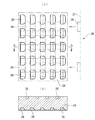
前記光拡散板24は、透明な合成樹脂による樹脂成形品であり、左面24Lと右面24Rのそれぞれに図10(a),(b)に一部を拡大して示したように、多数の拡散凹部26,26…が整列配置されている。具体的には、該拡散凹部26,26…が、左面24Lに対して碁盤の目の交差相当位置に整列配置され、一方、右面24Rに対して同じ碁盤の目の中央相当位置に整列配置されている。したがって左面24Lの拡散凹部26,26…と右面24Rの拡散凹部26,26…は位置的に重ならない。これにより、例えば右面24Rの拡散凹部26,26…に当たって左面24L側に反射する光が、左面24Lの拡散凹部26,26…同士の間からダイレクトに抜けるため、光の斑を少なくすることができる。
[Light diffusion plate]
The light diffusion plate 24 is a resin molded product made of a transparent synthetic resin. As shown in FIGS. 10 (a) and 10 (b), a plurality of diffusions are shown on the left surface 24L and the right surface 24R, respectively. The recesses 26, 26... Are aligned. More specifically, the diffusion recesses 26, 26,... Are aligned at positions corresponding to the intersections of the grids with respect to the left surface 24L, and are aligned at positions corresponding to the centers of the same grids with respect to the right surface 24R. ing. Therefore, the diffusion recesses 26, 26... On the left surface 24L and the diffusion recesses 26, 26. As a result, for example, light that hits the diffusion recesses 26, 26,... On the right surface 24R and reflects to the left surface 24L side is directly removed from between the diffusion recesses 26, 26,. .

前記表示部本体18の内部には、光拡散板24の後方端面に対応させて、照明基板27にLED等の発光体28を設けた発光手段29が設置されており、該発光手段29の光が光拡散板24の内部を通って拡散凹部26,26…で拡散され、そうして光拡散板24の左面24Lと右面24Rがほぼ同じ明るさで均等に光る。もっともその光は、各拡散凹部26,26…を明るさの中心にして例え僅かであっても斑が生じ得るため、僅かな斑を防ぐべく光拡散板24の左面24Lと右面24Rに、前記表示窓25,25とほぼ相似形でそれより一回り小さいスペーサー30,30がリブ状に突設されている。そうすることにより、光拡散板24と表示シート20L,20Rとの間に適度な間隔が保たれるため、光拡散板24から発せられる光が表示シート20L,20Rにソフトに当たる。よって表示シート20L,20Rに光の斑が生じにくい。   A light emitting means 29 provided with a light emitting body 28 such as an LED on the illumination board 27 is installed inside the display unit body 18 so as to correspond to the rear end face of the light diffusing plate 24. Are diffused by the diffusion recesses 26, 26... Through the inside of the light diffusing plate 24, and the left surface 24L and the right surface 24R of the light diffusing plate 24 shine evenly with substantially the same brightness. However, since the light may be slightly spotted with the diffusion recesses 26, 26... As the center of brightness, the light diffuser 24 has the left surface 24L and the right surface 24R to prevent the slight spot. Spacers 30, 30 that are substantially similar to the display windows 25, 25 and slightly smaller than the display windows 25 are provided in a rib shape. By doing so, an appropriate interval is maintained between the light diffusion plate 24 and the display sheets 20L and 20R, so that the light emitted from the light diffusion plate 24 hits the display sheets 20L and 20R softly. Therefore, light spots are hardly generated on the display sheets 20L and 20R.

なお、光拡散板24には、上端面と下端面にも水平面と垂直面が直交する直角三角形を階段状に並べた拡散段部31が形成されており、この拡散段部31によって上部方向と下部方向への前記発光手段29の光の拡散が促進されるため、光拡散板24の上端面と下端面も明るく光る。   The light diffusing plate 24 is also formed with a diffusion step portion 31 in which right-angled triangles whose horizontal and vertical planes are orthogonally arranged in a step shape on the upper end surface and the lower end surface. Since the light diffusion of the light emitting means 29 in the lower direction is promoted, the upper end surface and the lower end surface of the light diffusion plate 24 also shine brightly.

[表示シート]
前記表示シート20L,20Rは、透光性樹脂の薄いシートを、図11(a),(b)のように前記シート受部21に整合する形状に加工したものであり、同図に示した表面に図示を省略したがパチンコ機Pや遊技内容に関連する情報(機種名、遊技内容に関連するキャラクター等)が描かれている。また、この表示シート20L,20Rには、上部後方にシート受部21L,21Rへの出し入れを容易にするべく摘み片32が形成されている。
[Display sheet]
The display sheets 20L and 20R are obtained by processing a thin sheet of translucent resin into a shape that matches the sheet receiving portion 21 as shown in FIGS. 11 (a) and 11 (b). Although illustration is omitted on the surface, information related to the pachinko machine P and game content (model name, character related to game content, etc.) is drawn. Further, the display sheets 20L and 20R are formed with knobs 32 at the upper rear so as to facilitate the insertion and removal of the sheet receiving portions 21L and 21R.

なお、表示シート20L,20Rに描かれる情報は、左側部18L用と右側部18R用で統一してもよいが、好ましくは表示対象者に合わせて異ならせるのがよい。例えば、左側部18L用の表示シート20Lの表示対象者は、本パチンコ機Pを選択して現に遊技を行っている遊技者であり、一方、右側部18R用の表示シート20の表示対象者は、隣の別機種で遊技する遊技者或は機種選択のため島間の通路を行き来する遊技客であるから、左側部18L用の表示シート20Lには遊技内容に関連するキャラクターを描き、右側部18R用の表示シート20Rには機種宣伝用に機種名を表示する、という具合である。
実施形態では、それぞれの表示シート20L,20Rの表示内容が異なる場合の入れ違いを防止するため、図11(a)に表示シート20L,20R同士を重ねて相違する部分の輪郭を想像線で示したように、各表示シート20L,20R同士の形状を非同一にすると共にそれに合わせてシート受部21L,21R同士の形状も非同一にして、シート受部21L,21Rと表示シート20L,20Rの組合せが誤っている場合に、表示シート20L,20Rが正しく収容されないようにしてある。これにより表示シート20L,20Rの入れ違いを防止することができる。そしてさらに、図11(b)に示したように、一方の表示シート20に突片状の目印33(切欠状でもよい。)を設けて、表示シート20L,20Rの入れ違いを挿入段階でも発見し得るようにしている。これにより、表示シート20L,20Rの入れ違いによる無駄な作業が防止できる。
The information drawn on the display sheets 20L and 20R may be unified for the left side portion 18L and the right side portion 18R, but preferably different depending on the person to be displayed. For example, the display target person of the display sheet 20L for the left side part 18L is a player who is currently playing a game by selecting the pachinko machine P, while the display target person of the display sheet 20 for the right side part 18R is Since it is a player who plays in a different model next to it or a player who goes back and forth between the islands to select a model, a character related to the game content is drawn on the display sheet 20L for the left side 18L, and the right side 18R The model name is displayed on the display sheet 20R for model promotion.
In the embodiment, in order to prevent misplacement when the display contents of the display sheets 20L and 20R are different from each other, the outlines of the portions that are different from each other by overlapping the display sheets 20L and 20R are shown by imaginary lines in FIG. As described above, the shape of the display sheets 20L and 20R is made non-identical, and the shape of the sheet receiving portions 21L and 21R is made non-identical accordingly, and the sheet receiving portions 21L and 21R and the display sheets 20L and 20R are combined. Is incorrect, the display sheets 20L and 20R are not accommodated correctly. Thereby, it is possible to prevent the display sheets 20L and 20R from being inserted in the wrong direction. Further, as shown in FIG. 11 (b), one display sheet 20 is provided with a projecting mark 33 (may be a notch), and the insertion of the display sheets 20L and 20R is found at the insertion stage. Trying to get. Thereby, useless work due to the insertion of the display sheets 20L and 20R can be prevented.

[蓋部]
前記蓋部19は、光の透過が可能な透光部34を有するカバー部35と、表示部本体18の上面に整合する底部36と、右辺装飾部12の頂部前面に形成されたジョイント部37に整合する後部38と、を備えており、表示本体部2の上面と右辺装飾部12のジョイント部37とが交わるコーナー部分に底部36と後部38がフィットし、そのフィットした位置を閉じ位置として前記差込み口23,23を塞ぐ。
蓋部19は、摺動手段によって表示部本体18の上面に対して摺動可能に支持される一方、ロック手段39によって前記閉じ位置にロックされ、さらに回転手段によって略垂直方向に回動して表示部本体18の前面に保持される。
[Cover]
The lid portion 19 includes a cover portion 35 having a translucent portion 34 capable of transmitting light, a bottom portion 36 aligned with the upper surface of the display portion main body 18, and a joint portion 37 formed on the top front surface of the right side decoration portion 12. And the rear portion 38 is fitted to a corner portion where the upper surface of the display main body portion 2 and the joint portion 37 of the right side decoration portion 12 intersect, and the fitted position is defined as a closed position. The insertion ports 23 are closed.
The lid portion 19 is slidably supported by the sliding means with respect to the upper surface of the display unit main body 18, locked to the closed position by the locking means 39, and further rotated in a substantially vertical direction by the rotating means. It is held on the front surface of the display unit body 18.

[摺動手段]
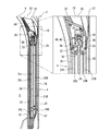
前記摺動手段は、図4A、図4B、図4C、図5に示したように、表示部本体18の上方に前記光拡散板24の上部を突出させてその上部の両側面に形成した直線状のガイド溝40と、蓋部19の底部36に形成された底開口41と、該底開口41の内壁に内向きに突設されていて前記ガイド溝40に嵌って摺動し得る一対の摺動突片42,42と、で形成されており、この摺動手段により蓋部19は、表示部本体18の上面に載った状態で前記閉じ位置から真っ直ぐ摺動し得る。なお、実施形態の表示部本体18の上面は、前記のように遊技者側に向けて下る勾配の傾斜を有するため、非ロック状態に置かれた蓋部19は、摺動手段による案内と自重により前記回転手段で回動する位置まで自動的に摺動し得る。
[Sliding means]
As shown in FIGS. 4A, 4B, 4C and 5, the sliding means is a straight line formed on both side surfaces of the upper part of the light diffusion plate 24 by projecting the upper part of the light diffusion plate 24 above the display unit body 18. A pair of guide grooves 40, a bottom opening 41 formed in the bottom 36 of the lid portion 19, and a pair of protrusions projecting inwardly on the inner wall of the bottom opening 41, which can slide into the guide grooves 40. The lid 19 can be slid straight from the closed position while being placed on the upper surface of the display unit body 18 by the sliding means. In addition, since the upper surface of the display unit main body 18 of the embodiment has a slope inclined downward toward the player side as described above, the lid portion 19 placed in the unlocked state is guided by the sliding means and its own weight. Thus, it can automatically slide to the position where it is rotated by the rotating means.

[ロック手段]
前記ロック手段39は、前記右辺装飾部12の頂部内に揺動可能に軸着された鉤部43と、該鉤部43を揺動させて蓋部19を閉じ位置にロックするロック姿勢とそのロックを解除するアンロック姿勢とに切り替える切替部44と、蓋部19の後部38に開設されたロック孔45と、からなる。
なお、補助的なロック手段として、図4Aの拡大図に示したように蓋部19の前記底開口41の前方側に、ガイド溝40の端部を挟むクリップ片46が設けられている。該クリップ片46によっても蓋部19は閉じ位置に止められるが、これは仮止め的なものであり、蓋部19を軽くスライドさせるだけで簡単に外すことができる。
[Locking means]
The locking means 39 includes a collar portion 43 pivotably mounted in the top of the right side decorative portion 12, a locking posture in which the collar portion 43 is pivoted to lock the lid portion 19 in a closed position, and The switch part 44 which switches to the unlocking posture which cancels | releases a lock | rock, and the lock hole 45 opened in the rear part 38 of the cover part 19 are comprised.
As an auxiliary locking means, as shown in the enlarged view of FIG. 4A, a clip piece 46 is provided on the front side of the bottom opening 41 of the lid portion 19 so as to sandwich the end portion of the guide groove 40. The lid 19 is also stopped at the closed position by the clip piece 46, but this is temporarily fixed and can be easily removed by simply sliding the lid 19 lightly.

[ロック手段−鉤部]
ロック手段39の前記鉤部43は、図4A、図4B、図4Cに示したように、ジョイント部37に開設したスリット47を通って閉じ位置にある蓋部19のロック孔45に係合し得る引掛片48と、該引掛片48の揺動中心部分から上向きに延設された連結アーム片49と、鉤部43をロック方向に付勢する巻きバネ50と、からなる。
[Locking means-buttock]
As shown in FIGS. 4A, 4B, and 4C, the flange portion 43 of the locking means 39 engages with the lock hole 45 of the lid portion 19 in the closed position through the slit 47 formed in the joint portion 37. The hook piece 48 to be obtained, the connecting arm piece 49 extending upward from the swinging center portion of the hook piece 48, and the winding spring 50 for urging the flange portion 43 in the locking direction.

[ロック手段−切替部]
ロック手段39の前記切替部44は、右辺装飾部12の頂部内に前後方向に摺動可能に支持された角軸状のスライダーであり、その前端に前記鉤部43の連結アーム片49の上端が回動自在に軸着され、一方、後端にボタン部44Pが形成されていて指先で押し引き操作が行えるようになっている。
該切替部44は、図4Cの想像線のように、後端のボタン部44Pを前面部3の後面に引き出すと前記鉤部43がアンロック姿勢に回動し(このときの切替部44の位置を「アンロック位置」という。)、また、同図実線のように、ボタン部44Pを前面部3の前面側に押し込むと前記鉤部43がロック姿勢に回動する(このときの切替部44の位置を「ロック位置」という。)。
[Locking means-switching section]
The switching portion 44 of the locking means 39 is a rectangular shaft-like slider supported in the top portion of the right side decorative portion 12 so as to be slidable in the front-rear direction, and has an upper end of the connecting arm piece 49 of the collar portion 43 at the front end thereof. Is pivotally mounted, and on the other hand, a button portion 44P is formed at the rear end so that a push-pull operation can be performed with a fingertip.
As shown in an imaginary line in FIG. 4C, when the button portion 44P at the rear end is pulled out to the rear surface of the front surface portion 3, the switching portion 44 rotates the collar portion 43 to the unlocked position (the switching portion 44 of this time) The position is referred to as an “unlock position”), and as shown by the solid line in FIG. 3, when the button portion 44P is pushed into the front surface side of the front surface portion 3, the collar portion 43 rotates to the locked position (the switching portion at this time). The position 44 is referred to as a “lock position”).

切替部44には、その上面前方側に、門型板バネ状の弾性部51に山型の突部52を設けてなる軽挙防止抵抗体53が一体に樹脂成形されており、切替部44が前記ロック位置からアンロック位置に、或はアンロック位置からロック位置に移動するとき、該軽挙防止抵抗体53の突部52が衝突する位置に固定的な障害ゲート54が設けられている。
したがって、切替部44は、後端のボタン部44Pに外力を加えて軽挙防止抵抗体53の突部52が弾性部51の弾性に抗して障害ゲート54の下を潜らない限り位置が変わらない。つまり、切替部44は、強制的に位置変更の外力を加えない限り、現状の位置(状態)を維持するようになっており、逆に切替部44に強制的な外力を加えることで現状の位置(状態)を切り替えることができる。なお、切替部44は、強制的な外力を加える前提として錠装置17で施錠されている前面部3を開く必要があるため、悪戯或は不正目的等で安易に蓋部19が開かれるおそれがない。
The switching portion 44 is integrally molded with an anti-minoring resistor 53 in which a mountain-shaped protrusion 52 is provided on an elastic portion 51 of a gate-shaped leaf spring on the front side of the upper surface. Is provided with a fixed fault gate 54 at a position where the projecting portion 52 of the lightning prevention resistor 53 collides when moving from the locked position to the unlocked position or from the unlocked position to the locked position. .
Therefore, the position of the switching unit 44 is changed unless an external force is applied to the button portion 44P at the rear end so that the protrusion 52 of the anti-rare resistance 53 is submerged under the obstacle gate 54 against the elasticity of the elastic portion 51. Absent. In other words, the switching unit 44 is configured to maintain the current position (state) unless the position change external force is forcibly applied. On the contrary, the switching unit 44 applies the forced external force to the current position. The position (state) can be switched. In addition, since the switching part 44 needs to open the front surface part 3 locked by the locking device 17 on the premise of applying a forced external force, there is a possibility that the cover part 19 can be easily opened for mischief or illegal purposes. Absent.

[回転手段]
前記回転手段は、表示部本体18の差込み口23の遊技者側のほぼ端部領域に回転中心55を設定して該回転中心55に対して前記蓋部19を垂直方向に回動させるものである。具体的には蓋部19の回転中心55は、図4A、図4Bに示したように、光拡散板24の上部側面であって前記ガイド溝40の下に並設された軸ガイド56の遊技者側の端部に設定されている。そして、この軸ガイド56に蓋部19の回動軸57が嵌って蓋部19と一体に摺動し、最終的に蓋部19の回動軸57が軸ガイド56の端部で止まって図4A、図4B二点鎖線のように垂直方向に回動し、かつその姿勢のままぶら下がり状態で保持される。
なお、実施形態の蓋部19の回動軸57は、図6の斜視図に示したように、蓋部19の内部に揺動自在に軸着された二股状のリンク58に設けられており、これにより蓋部19の摺動から回転に至る一連の動きが多関節的で滑らかに進行し得る。また、回動軸57は、二股状のリンク58の先端内面に突き合わせ状に突設され且つ互いが近接し合う方向に付勢された一対の凸部57a,57aで構成されるようになっており、したがってリンク58の二股部分を付勢に抗して拡開させて凸部57a,57a同士の間隔を広げることにより軸ガイド56に対して簡単に着脱することができる。つまり、表示部本体18に対して蓋部19を自由に着脱することができる。
[Rotating means]
The rotating means sets a rotation center 55 in an almost end region on the player side of the insertion port 23 of the display unit body 18 and rotates the lid portion 19 in the vertical direction with respect to the rotation center 55. is there. Specifically, as shown in FIGS. 4A and 4B, the rotation center 55 of the lid portion 19 is an upper side surface of the light diffusing plate 24, and the game of the shaft guide 56 arranged in parallel below the guide groove 40. It is set at the end of the person. Then, the rotation shaft 57 of the lid portion 19 is fitted into the shaft guide 56 and slides integrally with the lid portion 19, and finally the rotation shaft 57 of the lid portion 19 stops at the end portion of the shaft guide 56. 4A and 4B are rotated in the vertical direction as indicated by a two-dot chain line, and are held in a suspended state in the posture.
In addition, as shown in the perspective view of FIG. 6, the rotation shaft 57 of the lid portion 19 of the embodiment is provided on a bifurcated link 58 that is pivotally mounted inside the lid portion 19. As a result, a series of movements from sliding to rotation of the lid portion 19 can proceed smoothly in an articulated manner. Further, the rotation shaft 57 is configured by a pair of convex portions 57a and 57a projecting in abutting manner on the inner surface of the front end of the bifurcated link 58 and biased in a direction in which they approach each other. Therefore, the bifurcated portion of the link 58 is expanded against the biasing to widen the interval between the convex portions 57a, 57a, and can be easily attached to and detached from the shaft guide 56. That is, the lid portion 19 can be freely attached to and detached from the display portion main body 18.

実施形態のパチンコ機Pは、以上のように構成されているため、通常時には表示部4の各シート受部21L,21Rに表示シート20L,20Rがセットされ且つ蓋部19が閉じ位置にあってロック手段39でロックされている。
そして、営業時には、左辺装飾部10と上辺装飾部11と右辺装飾部12が内蔵された照明によって適宜装飾され、また、右辺装飾部12の表示部4に対応する発光手段29も点灯されて表示シート20L,20Rも明るく照らされている。
また、実施形態では、光拡散板24の頂部の拡散段部31が前記摺動手段に付随して蓋部19内にあるため、発光手段29の光が蓋部19内にも導入される。したがって、蓋部19に照明用の配線を施さずともカバー部35の透光部34をも明るく光らせることができる。
Since the pachinko machine P of the embodiment is configured as described above, the display sheets 20L and 20R are set in the sheet receiving portions 21L and 21R of the display unit 4 and the lid portion 19 is in the closed position at the normal time. Locked by the locking means 39.
At the time of business, the left side decoration unit 10, the upper side decoration unit 11, and the right side decoration unit 12 are appropriately decorated with illumination, and the light emitting means 29 corresponding to the display unit 4 of the right side decoration unit 12 is also turned on and displayed. The sheets 20L and 20R are also brightly illuminated.
In the embodiment, since the diffusion step portion 31 at the top of the light diffusing plate 24 is in the lid portion 19 in association with the sliding means, the light of the light emitting means 29 is also introduced into the lid portion 19. Therefore, the translucent portion 34 of the cover portion 35 can be brightly illuminated without providing the lid portion 19 with illumination wiring.

さらに実施形態のパチンコ機Pは、表示部4の上縁を遊技者側に向けて下る勾配に傾斜させ、そうして前記上辺装飾部11と表示部4の交差角部に通気用の空間が形成されるようにしたため、パチンコ機Pの前面に空気が滞留し難くなる。したがって、例えば煙草の煙がパチンコ機Pの前面に滞留するおそれがなく、また、熱気もこもりにくい。   Further, the pachinko machine P according to the embodiment is inclined so that the upper edge of the display unit 4 is inclined downward toward the player side, so that a space for ventilation is formed at the crossing corner of the upper side decoration unit 11 and the display unit 4. Since it is formed, air hardly stays in front of the pachinko machine P. Therefore, for example, there is no fear that cigarette smoke stays on the front surface of the pachinko machine P, and it is difficult for hot air to accumulate.

[表示シートの交換作業]
しかして、パチンコ機Pの遊技内容を変更する等の理由により、旧表示シート20L,20Rを遊技内容に対応した新しい表示シート20L,20Rに変更する場合は、先ず錠装置17を解錠して図8のように前面部3を開き、該前面部3の後面側から切替部44のボタン部44Pを引っ張る。そうするとその力で軽挙防止抵抗体53の突部52が弾性部51の弾性に抗して障害ゲート54の下を潜るため、切替部44が図4C二点鎖線のアンロック位置に移動する。これにより連結アーム片49の上端が引っ張られて鉤部43が揺動し、同図二点鎖線のようにアンロック姿勢に切り替わる。
[Replacement of display sheet]
Therefore, when the old display sheets 20L and 20R are changed to new display sheets 20L and 20R corresponding to the game contents due to reasons such as changing the game contents of the pachinko machine P, the lock device 17 is first unlocked. As shown in FIG. 8, the front surface portion 3 is opened, and the button portion 44 </ b> P of the switching portion 44 is pulled from the rear surface side of the front surface portion 3. As a result, the protrusion 52 of the lightning prevention resistor 53 is under the obstacle gate 54 against the elasticity of the elastic portion 51 by that force, so that the switching portion 44 is moved to the unlocked position in FIG. 4C. As a result, the upper end of the connecting arm piece 49 is pulled, and the collar portion 43 swings, and switches to the unlocked posture as shown by the two-dot chain line in FIG.

これにより鉤部43が蓋部19のロック孔45の縁から外れるためロック手段39による蓋部19のロックが解除される。なお、このとき鉤部43には、巻きバネ50の付勢によってロック姿勢に戻ろうとする力が作用するが、切替部44の軽挙防止抵抗体53の抵抗によりアンロック姿勢が維持される。   Thereby, since the collar part 43 comes off from the edge of the lock hole 45 of the cover part 19, the lock | rock of the cover part 19 by the locking means 39 is cancelled | released. At this time, a force to return to the locked posture is applied to the collar portion 43 by the urging of the winding spring 50, but the unlocked posture is maintained by the resistance of the lightning prevention resistor 53 of the switching portion 44.

一方、蓋部19は、ロック手段39によるロックが解除されても前記ように補助的なロック手段たる蓋部19のクリップ片46によって閉じ位置に止められているため、蓋部19を軽くスライドさせてクリップ片46をガイド溝40から外せば、後は前記摺動手段の作用と蓋部19の自重と表示部本体18の上面の傾斜によって、蓋部19が表示部本体18の遊技者側の端まで自動的に摺動する。もちろん蓋部19をそのまま手で摺動させても構わない。   On the other hand, since the lid portion 19 is stopped at the closed position by the clip piece 46 of the lid portion 19 as an auxiliary locking means as described above even if the lock by the locking means 39 is released, the lid portion 19 is lightly slid. Then, if the clip piece 46 is removed from the guide groove 40, the lid portion 19 on the player side of the display portion main body 18 is moved by the action of the sliding means, the weight of the lid portion 19 and the inclination of the upper surface of the display portion main body 18. It slides automatically to the end. Of course, the lid 19 may be slid by hand as it is.

次に蓋部19が摺動し、同時に回転手段の回動軸57が軸ガイド56内を摺動してその端に到達すると、その位置を回転中心55にして蓋部19が図4A二点鎖線、図4B二点鎖線、図7、図8のように垂直方向に回動して保持される。
これにより表示部本体18の差込み口23,23が完全に開くため、旧表示シート20L,20Rを抜き出して新しい表示シート20L,20Rに交換する。
Next, when the lid portion 19 is slid and at the same time the rotation shaft 57 of the rotating means slides in the shaft guide 56 and reaches its end, the lid portion 19 is positioned at the center of rotation 55 in FIG. It is held by rotating in the vertical direction as shown by a chain line, a two-dot chain line in FIG. 4B, and FIGS.
As a result, the insertion openings 23 and 23 of the display unit main body 18 are completely opened, so that the old display sheets 20L and 20R are extracted and replaced with new display sheets 20L and 20R.

なお、ここまでの説明で明らかなように実施形態の蓋部19は、摺動開始から回動して保持されるまで上方への嵩ばりが殆どない。したがって島設備の幕板前面のデータ表示体との干渉を考慮する必要がないため、前面部3の開き具合を極力小さくして表示シート20L,20Rの交換作業に要する体力を少なく抑制することができる。また、図7のように差込み口23,23を開いて保持されている状態の蓋部19が、表示シート20L,20Rを出し入れする方向になく差込み口23,23とほぼ同レベルの位置にあることで殆ど邪魔にならないため、表示シート20L,20Rの出し入れが効率よく行える。   As is apparent from the above description, the lid portion 19 of the embodiment has almost no upward bulk until it is rotated and held from the start of sliding. Accordingly, since it is not necessary to consider interference with the data display body on the front surface of the island facility screen, it is possible to reduce the physical strength required for the replacement work of the display sheets 20L and 20R by reducing the opening degree of the front surface portion 3 as much as possible. it can. Further, as shown in FIG. 7, the lid portion 19 in a state where the insertion ports 23 and 23 are opened and held is not positioned in the direction in which the display sheets 20L and 20R are taken in and out, and is located at substantially the same level as the insertion ports 23 and 23. Therefore, the display sheets 20L and 20R can be put in and out efficiently.

次に、上記手順を逆に実行して蓋部19を閉じ位置に戻し、切替部44のボタン部44Pを押し込んでロック手段39で蓋部19をロックし、そのまま前面部3を閉じれば表示シート20L,20Rの交換作業が完了する。
なお、切替部44のボタン部44Pの操作は、前面部3を本体部2の前面に重ねたとき、その本体部2の前面で押し込まれるように設定しておけば、あえて手でボタン部44Pを押し込む必要はない。また、かかる設定にすることで、ロック手段39による蓋部19のロックを失念する過誤が防止できるため、蓋部19を外した部分から機内への侵入を図ろうとする不正行為に対しても有効な対策になり得る。
Next, the above procedure is reversed to return the lid 19 to the closed position, push the button 44P of the switching unit 44, lock the lid 19 with the lock means 39, and close the front face 3 as it is to display the sheet. The replacement work of 20L and 20R is completed.
The operation of the button unit 44P of the switching unit 44 can be performed by manually setting the button unit 44P by hand if the front unit 3 is set to be pushed in front of the main unit 2 when the front unit 3 is superimposed on the front of the main unit 2. There is no need to push in. In addition, this setting can prevent an error that forgets the locking of the lid portion 19 by the locking means 39, so that it is also effective against illegal acts that attempt to enter the aircraft from the portion where the lid portion 19 is removed. Can be a good countermeasure.

ところでロック手段39の操作が正常でも、蓋部19の閉じ位置へのセットが不十分であった場合にはロックが正しく行われないおそれがある。そのような事態を回避するため、好ましくは蓋部19の閉じ位置へのセットが正常であることを検知するセンサーを設け、もしセットが不十分であった場合には、前面部3を閉じた時、アラームを鳴らすなどの報知手段を設けておくとよい。   By the way, even if the operation of the lock means 39 is normal, there is a possibility that the lock may not be performed correctly if the lid 19 is not sufficiently set to the closed position. In order to avoid such a situation, a sensor for detecting that the cover 19 is normally set to the closed position is provided, and if the setting is insufficient, the front face 3 is closed. It is advisable to provide notification means such as sounding an alarm.

以上、本発明を実施の形態について説明したが、もちろん本発明は上記実施形態に限定されるものではない。例えば実施形態では、表示部本体18の上面に傾斜を設けて自重によって蓋部19を開位置方向に付勢するようにしたが、表示部本体18の上面を水平にした場合でも、手動によって蓋部19を摺動させたり、或は、バネなどの弾性で蓋部19を開位置方向に付勢するようにしてもよい。もっとも実施形態のように傾斜による重力を利用する構造が最もシンプルで低コストであり且つ故障のおそれも少ない点で有用性がある。   As mentioned above, although embodiment of this invention was described, of course, this invention is not limited to the said embodiment. For example, in the embodiment, the upper surface of the display unit body 18 is inclined and the lid 19 is urged in the open position direction by its own weight. However, even when the upper surface of the display unit body 18 is horizontal, the lid is manually opened. The portion 19 may be slid, or the lid portion 19 may be biased in the open position direction by elasticity such as a spring. However, as in the embodiment, the structure using gravity by inclination is the simplest, low cost, and useful in that there is little risk of failure.

また、実施形態では、前面部3を一枚構造にしたが、上の球皿13と窓部9の間で上下に分割して形成してもよい。
また、実施形態では遊技機としてパチンコ機Pを例示したが、スロットマシンであっても適用可能である。
In the embodiment, the front surface portion 3 has a single structure. However, the front surface portion 3 may be divided into upper and lower portions between the upper ball tray 13 and the window portion 9.
In the embodiment, the pachinko machine P is exemplified as the gaming machine, but the present invention can also be applied to a slot machine.

P …パチンコ機(遊技機)
1 …外枠
3 …前面部
4 …表示部
18 …表示部本体
19 …蓋部
20L,20R …表示シート
21L,21R …シート受部
23,23 …差込み口
40 …ガイド溝(摺動手段)
41 …底開口(摺動手段)
42,42 …摺動突片(摺動手段)
55 …回転中心(回転手段)
56 …軸ガイド(回転手段)
57 …回動軸(回転手段)
57a,57a …凸部(回転手段)
58 …リンク(回転手段)
P: Pachinko machine (game machine)
DESCRIPTION OF SYMBOLS 1 ... Outer frame 3 ... Front part 4 ... Display part 18 ... Display part main body 19 ... Lid part 20L, 20R ... Display sheet 21L, 21R ... Sheet receiving part 23, 23 ... Insertion port 40 ... Guide groove (sliding means)
41 ... Bottom opening (sliding means)
42, 42 ... sliding protrusion (sliding means)
55 ... Center of rotation (rotating means)
56 ... Shaft guide (rotating means)
57… Rotating shaft (rotating means)
57a, 57a ... convex portion (rotating means)
58 ... Link (rotating means)

Claims (1)

遊技機の前面側を構成する前扉と、
前記前扉の所定位置に位置する固定状態と、前記前扉の前記所定位置に位置しない非固定状態とに変化可能であり、前記固定状態にあるときに当該遊技機の装飾の一部を担う特定部材と、を備え、
前記特定部材は、所定の解除部が操作されることで非固定状態に変化し、該非固定状態では所定の摺動部に沿って摺動可能であり、該摺動を経て当該遊技機から離脱しうるものであって、
前記摺動部は、当該遊技機の前後方向に延びたレールであり、
前記特定部材は、前記摺動によって前記前扉から離れる方向に移動した後、離脱しうるようになっており、
前記特定部材が離脱するときには、前記特定部材の姿勢が前記固定状態にあるときと異なった姿勢になるように構成されてなることを特徴とする遊技機。
A front door constituting the front side of the gaming machine,
It is possible to change between a fixed state where the front door is located at a predetermined position and an unfixed state where the front door is not located at the predetermined position, and bears part of the decoration of the gaming machine when in the fixed state. A specific member,
The specific member changes to a non-fixed state when a predetermined release portion is operated, and can slide along the predetermined sliding portion in the non-fixed state, and is detached from the gaming machine through the sliding. It can be
The sliding portion is a rail extending in the front-rear direction of the gaming machine,
The specific member can be detached after moving in a direction away from the front door by the sliding,
The gaming machine is configured such that when the specific member is detached, the specific member has a posture different from that in the fixed state .
JP2015069664A 2015-03-30 2015-03-30 Game machine Active JP6460880B2 (en)

Priority Applications (1)

Application Number Priority Date Filing Date Title
JP2015069664A JP6460880B2 (en) 2015-03-30 2015-03-30 Game machine

Applications Claiming Priority (1)

Application Number Priority Date Filing Date Title
JP2015069664A JP6460880B2 (en) 2015-03-30 2015-03-30 Game machine

Publications (3)

Publication Number Publication Date
JP2016187524A JP2016187524A (en) 2016-11-04
JP2016187524A5 JP2016187524A5 (en) 2018-04-05
JP6460880B2 true JP6460880B2 (en) 2019-01-30

Family

ID=57240213

Family Applications (1)

Application Number Title Priority Date Filing Date
JP2015069664A Active JP6460880B2 (en) 2015-03-30 2015-03-30 Game machine

Country Status (1)

Country Link
JP (1) JP6460880B2 (en)

Families Citing this family (2)

* Cited by examiner, † Cited by third party
Publication number Priority date Publication date Assignee Title
JP7198515B2 (en) * 2020-06-30 2023-01-04 株式会社サンセイアールアンドディ game machine
JP7578871B2 (en) * 2020-09-11 2024-11-07 サミー株式会社 Gaming Machines

Family Cites Families (5)

* Cited by examiner, † Cited by third party
Publication number Priority date Publication date Assignee Title
JPS5642805Y2 (en) * 1976-04-26 1981-10-07
JP2931958B2 (en) * 1996-05-21 1999-08-09 栄一郎 後藤 Ashtray
JP2009063341A (en) * 2007-09-05 2009-03-26 Seiko Instruments Inc Electronic metronome
JP5133712B2 (en) * 2008-01-11 2013-01-30 株式会社平和 Game machine
JP5775483B2 (en) * 2012-04-17 2015-09-09 株式会社藤商事 Game machine

Also Published As

Publication number Publication date
JP2016187524A (en) 2016-11-04

Similar Documents

Publication Publication Date Title
JP5775483B2 (en) Game machine
JP2003052983A (en) Ball game machine
JP6460880B2 (en) Game machine
JP5780562B2 (en) Game machine
JP6362169B2 (en) Game machine
JP2016202815A (en) Game machine
JP6460480B2 (en) Game machine
JP2005013545A (en) Pinball game machine
JP2016202816A (en) Game machine
JP6040479B2 (en) Game machine
JP6171068B1 (en) Game machine
JP5942116B2 (en) Game machine
JP5023302B2 (en) Game machine
JP2009112661A (en) Game machine
JP6892317B2 (en) Pachinko machine
JP3928950B2 (en) Pachinko machine
JP5382159B2 (en) Game machine
JP4913017B2 (en) Pachinko machine
JP5429318B2 (en) Game machine
JP4390280B2 (en) Game machine
JP5842878B2 (en) Game machine
JP2016083511A (en) Game machine
JP2024033470A (en) Game machine
JP2016083510A (en) Game machine
JP5494706B2 (en) Game machine

Legal Events

Date Code Title Description
A621 Written request for application examination

Free format text: JAPANESE INTERMEDIATE CODE: A621

Effective date: 20170712

A521 Request for written amendment filed

Free format text: JAPANESE INTERMEDIATE CODE: A523

Effective date: 20180223

A977 Report on retrieval

Free format text: JAPANESE INTERMEDIATE CODE: A971007

Effective date: 20180427

A131 Notification of reasons for refusal

Free format text: JAPANESE INTERMEDIATE CODE: A131

Effective date: 20180515

A521 Request for written amendment filed

Free format text: JAPANESE INTERMEDIATE CODE: A523

Effective date: 20180717

TRDD Decision of grant or rejection written
A01 Written decision to grant a patent or to grant a registration (utility model)

Free format text: JAPANESE INTERMEDIATE CODE: A01

Effective date: 20181225

A61 First payment of annual fees (during grant procedure)

Free format text: JAPANESE INTERMEDIATE CODE: A61

Effective date: 20181225

R150 Certificate of patent or registration of utility model

Ref document number: 6460880

Country of ref document: JP

Free format text: JAPANESE INTERMEDIATE CODE: R150

R250 Receipt of annual fees

Free format text: JAPANESE INTERMEDIATE CODE: R250

R250 Receipt of annual fees

Free format text: JAPANESE INTERMEDIATE CODE: R250