JP6453407B2 - Gas turbine rotor and gas turbine - Google Patents
Gas turbine rotor and gas turbine Download PDFInfo
- Publication number
- JP6453407B2 JP6453407B2 JP2017180277A JP2017180277A JP6453407B2 JP 6453407 B2 JP6453407 B2 JP 6453407B2 JP 2017180277 A JP2017180277 A JP 2017180277A JP 2017180277 A JP2017180277 A JP 2017180277A JP 6453407 B2 JP6453407 B2 JP 6453407B2
- Authority
- JP
- Japan
- Prior art keywords
- rotor
- gas turbine
- connecting member
- peripheral surface
- predetermined length
- Prior art date
- Legal status (The legal status is an assumption and is not a legal conclusion. Google has not performed a legal analysis and makes no representation as to the accuracy of the status listed.)
- Active
Links
- 238000003780 insertion Methods 0.000 claims description 58
- 230000037431 insertion Effects 0.000 claims description 58
- 239000000463 material Substances 0.000 claims description 31
- 230000002093 peripheral effect Effects 0.000 claims description 28
- 239000012809 cooling fluid Substances 0.000 claims description 3
- 230000008878 coupling Effects 0.000 claims description 3
- 238000010168 coupling process Methods 0.000 claims description 3
- 238000005859 coupling reaction Methods 0.000 claims description 3
- 239000007789 gas Substances 0.000 description 80
- 230000004323 axial length Effects 0.000 description 12
- 239000000567 combustion gas Substances 0.000 description 4
- 238000002485 combustion reaction Methods 0.000 description 3
- 238000001816 cooling Methods 0.000 description 2
- 239000000446 fuel Substances 0.000 description 2
- 230000001939 inductive effect Effects 0.000 description 2
- 238000004519 manufacturing process Methods 0.000 description 2
- 125000004122 cyclic group Chemical group 0.000 description 1
- 238000010586 diagram Methods 0.000 description 1
- 239000012530 fluid Substances 0.000 description 1
- 238000010248 power generation Methods 0.000 description 1
- 238000000926 separation method Methods 0.000 description 1
Images


Classifications
-
- F—MECHANICAL ENGINEERING; LIGHTING; HEATING; WEAPONS; BLASTING
- F01—MACHINES OR ENGINES IN GENERAL; ENGINE PLANTS IN GENERAL; STEAM ENGINES
- F01D—NON-POSITIVE DISPLACEMENT MACHINES OR ENGINES, e.g. STEAM TURBINES
- F01D25/00—Component parts, details, or accessories, not provided for in, or of interest apart from, other groups
- F01D25/24—Casings; Casing parts, e.g. diaphragms, casing fastenings
- F01D25/243—Flange connections; Bolting arrangements
-
- F—MECHANICAL ENGINEERING; LIGHTING; HEATING; WEAPONS; BLASTING
- F01—MACHINES OR ENGINES IN GENERAL; ENGINE PLANTS IN GENERAL; STEAM ENGINES
- F01D—NON-POSITIVE DISPLACEMENT MACHINES OR ENGINES, e.g. STEAM TURBINES
- F01D25/00—Component parts, details, or accessories, not provided for in, or of interest apart from, other groups
- F01D25/08—Cooling; Heating; Heat-insulation
- F01D25/12—Cooling
-
- F—MECHANICAL ENGINEERING; LIGHTING; HEATING; WEAPONS; BLASTING
- F01—MACHINES OR ENGINES IN GENERAL; ENGINE PLANTS IN GENERAL; STEAM ENGINES
- F01D—NON-POSITIVE DISPLACEMENT MACHINES OR ENGINES, e.g. STEAM TURBINES
- F01D25/00—Component parts, details, or accessories, not provided for in, or of interest apart from, other groups
- F01D25/08—Cooling; Heating; Heat-insulation
- F01D25/14—Casings modified therefor
-
- F—MECHANICAL ENGINEERING; LIGHTING; HEATING; WEAPONS; BLASTING
- F01—MACHINES OR ENGINES IN GENERAL; ENGINE PLANTS IN GENERAL; STEAM ENGINES
- F01D—NON-POSITIVE DISPLACEMENT MACHINES OR ENGINES, e.g. STEAM TURBINES
- F01D5/00—Blades; Blade-carrying members; Heating, heat-insulating, cooling or antivibration means on the blades or the members
- F01D5/02—Blade-carrying members, e.g. rotors
- F01D5/06—Rotors for more than one axial stage, e.g. of drum or multiple disc type; Details thereof, e.g. shafts, shaft connections
- F01D5/066—Connecting means for joining rotor-discs or rotor-elements together, e.g. by a central bolt, by clamps
-
- F—MECHANICAL ENGINEERING; LIGHTING; HEATING; WEAPONS; BLASTING
- F05—INDEXING SCHEMES RELATING TO ENGINES OR PUMPS IN VARIOUS SUBCLASSES OF CLASSES F01-F04
- F05D—INDEXING SCHEME FOR ASPECTS RELATING TO NON-POSITIVE-DISPLACEMENT MACHINES OR ENGINES, GAS-TURBINES OR JET-PROPULSION PLANTS
- F05D2230/00—Manufacture
- F05D2230/60—Assembly methods
-
- F—MECHANICAL ENGINEERING; LIGHTING; HEATING; WEAPONS; BLASTING
- F05—INDEXING SCHEMES RELATING TO ENGINES OR PUMPS IN VARIOUS SUBCLASSES OF CLASSES F01-F04
- F05D—INDEXING SCHEME FOR ASPECTS RELATING TO NON-POSITIVE-DISPLACEMENT MACHINES OR ENGINES, GAS-TURBINES OR JET-PROPULSION PLANTS
- F05D2230/00—Manufacture
- F05D2230/90—Coating; Surface treatment
-
- F—MECHANICAL ENGINEERING; LIGHTING; HEATING; WEAPONS; BLASTING
- F05—INDEXING SCHEMES RELATING TO ENGINES OR PUMPS IN VARIOUS SUBCLASSES OF CLASSES F01-F04
- F05D—INDEXING SCHEME FOR ASPECTS RELATING TO NON-POSITIVE-DISPLACEMENT MACHINES OR ENGINES, GAS-TURBINES OR JET-PROPULSION PLANTS
- F05D2240/00—Components
- F05D2240/60—Shafts
-
- F—MECHANICAL ENGINEERING; LIGHTING; HEATING; WEAPONS; BLASTING
- F05—INDEXING SCHEMES RELATING TO ENGINES OR PUMPS IN VARIOUS SUBCLASSES OF CLASSES F01-F04
- F05D—INDEXING SCHEME FOR ASPECTS RELATING TO NON-POSITIVE-DISPLACEMENT MACHINES OR ENGINES, GAS-TURBINES OR JET-PROPULSION PLANTS
- F05D2260/00—Function
- F05D2260/30—Retaining components in desired mutual position
- F05D2260/31—Retaining bolts or nuts
-
- Y—GENERAL TAGGING OF NEW TECHNOLOGICAL DEVELOPMENTS; GENERAL TAGGING OF CROSS-SECTIONAL TECHNOLOGIES SPANNING OVER SEVERAL SECTIONS OF THE IPC; TECHNICAL SUBJECTS COVERED BY FORMER USPC CROSS-REFERENCE ART COLLECTIONS [XRACs] AND DIGESTS
- Y02—TECHNOLOGIES OR APPLICATIONS FOR MITIGATION OR ADAPTATION AGAINST CLIMATE CHANGE
- Y02T—CLIMATE CHANGE MITIGATION TECHNOLOGIES RELATED TO TRANSPORTATION
- Y02T50/00—Aeronautics or air transport
- Y02T50/60—Efficient propulsion technologies, e.g. for aircraft
Landscapes
- Engineering & Computer Science (AREA)
- Mechanical Engineering (AREA)
- General Engineering & Computer Science (AREA)
- Turbine Rotor Nozzle Sealing (AREA)
- Structures Of Non-Positive Displacement Pumps (AREA)
Description
本発明は、ガスタービンローター及びガスタービンに係り、より詳しくは、ガスタービンローターの軸方向長さ調節構造を有するガスタービンローターと、これを含むガスタービンに関する。 The present invention relates to a gas turbine rotor and a gas turbine, and more particularly to a gas turbine rotor having an axial length adjustment structure of a gas turbine rotor and a gas turbine including the same.
一般に、ガスタービンは、圧縮機、燃焼器及びタービンから構成されている。空気導入口を介して吸入された空気が圧縮機で圧縮されることにより、高温、高圧の圧縮空気となり、この圧縮空気に対して燃焼器で燃料を供給して燃焼させることにより、高温・高圧の燃焼ガス(作動流体)を得、この燃焼ガスによってタービンを駆動し、このタービンに連結された発電機を駆動する。
ガスタービンエンジンは、一種の回転式内燃機関であり、高温・高圧の燃焼ガスを膨張させ、タービンを回して回転力を得る機関である。
すなわち、圧縮機を通過して昇圧した空気を燃焼室へ供給し、圧縮空気を燃料と混合して燃焼室で摂氏800〜1200℃の高温ガスにした後、圧縮機の所要出力が得られる圧力比までタービンで膨張させ、回転するタービンの出力を用いて発電機を回し、さらには排出される高温の燃焼ガスを複合発電に利用したりもする。その他の航空機用ガスタービンエンジンは、タービンから排出されるガスをジェットノズルから高速で噴出させて推進力を得ることもある。ガスタービンを構成する圧縮機とタービンは、それぞれベーン(vane)とブレード(blade)を含むが、回転体であるブレードは、一つの軸で連結されたローターによって一緒に回転する。すなわち、タービンの回転動力の一部を圧縮機の駆動動力として用いる。
In general, a gas turbine is composed of a compressor, a combustor, and a turbine. The air sucked through the air inlet is compressed by a compressor to become high-temperature and high-pressure compressed air, and fuel is supplied to the compressed air by a combustor and burned. The combustion gas (working fluid) is obtained, the turbine is driven by the combustion gas, and the generator connected to the turbine is driven.
A gas turbine engine is a kind of rotary internal combustion engine that expands high-temperature and high-pressure combustion gas and rotates a turbine to obtain rotational force.
That is, after the compressed air is passed through the compressor and supplied to the combustion chamber, the compressed air is mixed with the fuel to form a high-temperature gas at 800 to 1200 ° C. in the combustion chamber, and then the pressure at which the required output of the compressor is obtained. The turbine is expanded to a specific ratio, the generator is rotated using the output of the rotating turbine, and the exhausted high-temperature combustion gas is used for combined power generation. Other aircraft gas turbine engines may obtain propulsion by ejecting gas exhausted from the turbine at high speed from a jet nozzle. The compressor and the turbine that constitute the gas turbine each include a vane and a blade, but the blade, which is a rotating body, rotates together by a rotor connected by a single shaft. That is, a part of the rotational power of the turbine is used as the driving power for the compressor.
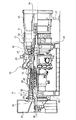
図1に示すように、従来技術によるガスタービンの場合は、非常に精密に製作されて運用されなければならない。特にガスタービンローターの場合、ガスタービンの始動区間で軸長が熱膨張によって次第に変化する。これまでの殆どのガスタービンは、ローターの軸方向クリアランス(clearance)を調節することが可能ではなく、ガスタービンローターの軸方向長さの変化に応じてベーン及びブレードの位置が変化し、ベーン及びブレードの位置変更は空力学的特性の変動を起こし、結果としてガスタービン全体の出力及び効率に変化が起こるという問題点がある。
したがって、上述の問題点を解決することができるガスタービンローター及びこれを含むガスタービンが求められている。
As shown in FIG. 1, the gas turbine according to the prior art must be manufactured and operated very precisely. In particular, in the case of a gas turbine rotor, the axial length gradually changes due to thermal expansion in the starting section of the gas turbine. Most previous gas turbines are unable to adjust the rotor's axial clearance, and the vane and blade positions change in response to changes in the axial length of the gas turbine rotor. The blade position change causes a change in aerodynamic characteristics, resulting in a change in the output and efficiency of the entire gas turbine.
Therefore, there is a need for a gas turbine rotor that can solve the above-described problems and a gas turbine including the same.
本発明の目的は、タービンの半径方向クリアランス(clearance)を調節することができるガスタービンローター及びこれを含むガスタービンを提供することにある。 It is an object of the present invention to provide a gas turbine rotor capable of adjusting a radial clearance of the turbine and a gas turbine including the same.
上記目的を達成するため、本発明によるガスタービンローターは、外周面に圧縮機及びタービンのブレードを装着して回転駆動するガスタービンローターであって、一方向に所定の長さだけ延長された軸構造であり、一端部には第2ローターの挿入部が挿入できる挿入溝を有する第1ローターと、一方向に所定の長さだけ延長された軸構造であり、一端部には第1ローターに設けられた挿入溝と対応する構造で所定の長さだけ延設される挿入部を有する第2ローターと、前記挿入溝と前記挿入部との間に装着され、前記第1ローターと前記第2ローターとを互いに結束させ、前記第1ローター及び前記第2ローターを構成する素材とは熱膨張率が異なる素材で構成された連結部材と、を含み、前記第1ローター及び前記第2ローターの内部には、冷却流体が流動することが可能な第1流動路が設けられていることを特徴とする。
In order to achieve the above object, a gas turbine rotor according to the present invention is a gas turbine rotor that is rotationally driven by mounting a compressor and a turbine blade on an outer peripheral surface thereof, and is a shaft that is extended by a predetermined length in one direction. A first rotor having an insertion groove into which an insertion portion of the second rotor can be inserted at one end, and a shaft structure extended in one direction by a predetermined length, and the first rotor at one end A second rotor having an insertion portion extended by a predetermined length in a structure corresponding to the provided insertion groove, and mounted between the insertion groove and the insertion portion, the first rotor and the second rotor; a rotor is bundled together, the saw including a connecting member having a thermal expansion rate is made of different materials, the the first rotor and the material constituting the second rotor, the first rotor and the second rotor Inside , Wherein the first flow passage cooling fluid capable of flowing is provided.
前記第1ローターの一端部には、外周面に沿って一定の間隔でボルト孔が設けられ、第1ローターの一端部に結束される連結部材の一側部には、ボルト孔と対応する位置に貫通孔が設けられ、前記ボルト孔と前記貫通孔を用いて第1ローターと連結部材とが互いにボルト締結されることを特徴とする。 Bolt holes are provided at one end of the first rotor at regular intervals along the outer peripheral surface, and one side of the connecting member bound to the one end of the first rotor has a position corresponding to the bolt hole. The first rotor and the connecting member are bolted to each other using the bolt hole and the through hole.
前記挿入部の一端部には、外周面に沿って一定の間隔でボルト孔が設けられ、挿入部の一端部に結束される連結部材の一側部には、ボルト孔と対応する位置に貫通孔が設けられ、前記ボルト孔と前記貫通孔を用いて第2ローターと連結部材とが互いにボルト締結されることを特徴とする。 Bolt holes are provided at one end portion of the insertion portion at regular intervals along the outer peripheral surface, and one side portion of the connecting member bound to the one end portion of the insertion portion penetrates to a position corresponding to the bolt hole. A hole is provided, and the second rotor and the connecting member are bolted to each other using the bolt hole and the through hole.
前記連結部材は、熱膨張率の異なる2種以上の素材から一定のパターンで配置されて構成されることを特徴とする。 The connecting member is configured by being arranged in a certain pattern from two or more kinds of materials having different coefficients of thermal expansion.
前記連結部材は、第1ローターの一端部に結束される第1連結部と、第1連結部と第2連結部とを一体に連結し、挿入部の外周面に対応する構造で所定の長さだけ延設された延長部と、第2ローターの一端部に結束される第2連結部と、を含むことを特徴とする。 The connecting member integrally connects the first connecting part bound to one end of the first rotor, the first connecting part, and the second connecting part, and has a structure corresponding to the outer peripheral surface of the insertion part and has a predetermined length. It is characterized by including the extension part extended only by this, and the 2nd connection part tied to the one end part of a 2nd rotor.
また、前記挿入溝の内周面と挿入部の外周面とが互いに離隔した距離は、延長部の厚さに対して100〜110%であることが好ましい。 Moreover, it is preferable that the distance which the inner peripheral surface of the said insertion groove | channel and the outer peripheral surface of the insertion part mutually separated is 100 to 110% with respect to the thickness of an extension part.
また、前記連結部材は、側断面視で、第1ローター及び第2ローターの外径に対応する外径で形成された環状型の構造をなすことを特徴とする。 The connecting member may have an annular structure formed with an outer diameter corresponding to the outer diameters of the first rotor and the second rotor in a side sectional view.
前記連結部材は、2つ以上が互いに結合され、側断面視で第1ローター及び第2ローターの外径に対応する環状型の構造をなすことを特徴とする。明の一実施形態において、前記延長部は、熱膨張率の異なる2種以上の素材から一定のパターンで配置されて構成されることを特徴とする。 Two or more connecting members are coupled to each other, and have an annular structure corresponding to the outer diameters of the first rotor and the second rotor in a side sectional view. In one embodiment of the present invention, the extension part is configured by being arranged in a certain pattern from two or more kinds of materials having different coefficients of thermal expansion.
前記第1ローターと連結部材とが互いに接触する面、及び第2ローターと連結部材とが互いに接触する面には、熱伝達物質が塗布されることを特徴とする。 A heat transfer material is applied to a surface where the first rotor and the connection member are in contact with each other and a surface where the second rotor and the connection member are in contact with each other.
また、前記連結部材の内部には、第1流動路に連通する第2流動路が設けられることを特徴とする。 Further, a second flow path communicating with the first flow path is provided inside the connecting member.
また、前記第2流動路は、連結部材の延長方向と平行な方向に設けられることを特徴とする。 The second flow path is provided in a direction parallel to the extending direction of the connecting member.
また、前記第2流動路は、一定の距離だけ離隔して複数個が設けられることを特徴とする。 In addition, a plurality of the second flow paths are provided apart from each other by a certain distance.
本発明によるガスタービンは、外周面に圧縮機及びガスタービンのブレードを装着して回転駆動するガスタービンローターを含むガスタービンであって、前記ガスタービンローターは、一方向に所定の長さだけ延長された軸構造であり、一端部には第2ローターの端部が挿入できる挿入溝を有する第1ローターと、一方向に所定の長さだけ延長された軸構造であり、一端部には前記第1ローターに設けられた挿入溝と対応する構造で所定の長さだけ延設された挿入部を有する第2ローターと、前記挿入溝と前記挿入部との間に装着され、前記第1ローターと前記第2ローターとを互いに結束させ、前記第1ローター及び前記第2ローターを構成する素材とは熱膨張率が異なる素材で構成された連結部材と、を含み、前記連結部材は、側断面視で、前記第1ローター及び前記第2ローターの外径と対応する外径で形成された環状型の構造をなすことを特徴とする。
A gas turbine according to the present invention is a gas turbine including a gas turbine rotor that is rotationally driven by mounting a compressor and a blade of the gas turbine on an outer peripheral surface, and the gas turbine rotor extends in a single direction by a predetermined length. A first rotor having an insertion groove into which an end of the second rotor can be inserted at one end, and a shaft structure extended in one direction by a predetermined length. A first rotor having a structure corresponding to an insertion groove provided in the first rotor and having an insertion portion extended by a predetermined length; and mounted between the insertion groove and the insertion portion; the second rotor and were bundled together, said saw including a connecting member having a thermal expansion rate is made of different materials, the the first rotor and the material constituting the second rotor, wherein the coupling member side as the Sectional view Characterized by forming a cyclic structure type formed by an outer diameter corresponding to the outer diameter of the first rotor and the second rotor.
前記連結部材は、第1ローターの一端部に結束される第1連結部と、第1連結部と第2連結部とを一体に連結し、挿入部の外周面に対応する構造で所定の長さだけ延設された延長部と、第2ローターの一端部に結束される第2連結部と、を含んで構成されることを特徴とする。 The connecting member integrally connects the first connecting part bound to one end of the first rotor, the first connecting part, and the second connecting part, and has a structure corresponding to the outer peripheral surface of the insertion part and has a predetermined length. It is characterized by including the extension part extended and the 2nd connection part tied to the one end part of a 2nd rotor.
前記連結部材は、熱膨張率の異なる2種以上の素材から一定のパターンで配置されて構成されることを特徴とする。 The connecting member is configured by being arranged in a certain pattern from two or more kinds of materials having different coefficients of thermal expansion.
前記連結部材は、2つ以上が互いに結合され、側断面視で、第1ローター及び第2ローターの外径に対応する環状型の構造をなすことを特徴とする。 Two or more connecting members are coupled to each other, and have an annular structure corresponding to the outer diameters of the first rotor and the second rotor in a side sectional view.
本発明のガスタービンローターによれば、特定の構造の第1ローター、第2ローター及び連結部材を備えるので、ガスタービンの始動区間でガスタービンローターの軸方向長さを調節することにより、タービンの半径方向クリアランス(clearance)を調節することができる。また、これを含むガスタービンを提供することができる。
また、本発明のガスタービンローターによれば、第1ローター及び第2ローターの一端部に設けられたボルト孔、及び連結部材に設けられた貫通孔を用いて、連結部材を第1ローターと第2ローターに強固かつ安定的にボルト締結することができるため、ガスタービンローターの安定な構造を実現することができる。
また、本発明のガスタービンローターによれば、第1ローターと第2ローターを構成する素材とは熱膨張率が異なる素材で連結部材を構成することにより、ガスタービンの始動区間でガスタービンローターの昇温に応じてガスタービンローターの軸方向長さを調節することができ、これにより、タービンの半径方向クリアランス(clearance)を調節することができる。また、これを含むガスタービンを提供することができる。
また、本発明のガスタービンローターによれば、用途及び順序に応じて、互いに異なる熱膨張率を持つ2種以上の素材を連結部材に適用することにより、ガスタービンの始動区間でガスタービンローターの昇温に応じてガスタービンローターの軸方向長さを調節することができる。これによりタービンの半径方向クリアランス(clearance)を調節することができる。また、これを含むガスタービンを提供することができる。
また、本発明のガスタービンローターによれば、挿入溝の内周面と挿入部の外周面とが互いに離隔した距離を、延長部の厚さに対して特定の範囲に限定することにより、連結部材の熱変形によるガスタービンローターの全長の調節をより正確かつ安定的に実現することができる。
また、本発明のガスタービンローターによれば、特定の構造の第1流動路及び第2流動路を備えることにより、第1流動路と第2流動路を用いて冷却空気を流動させて第1ローター、第2ローター及び連結部材の熱変形による軸方向長さを容易に調節することができる。
また、本発明のガスタービンによれば、特定の構成のガスタービンローターを備えることにより、ガスタービンの始動区間でガスタービンローターの昇温に応じてガスタービンローターの軸方向長さを調節することができ、これによりタービンの半径方向クリアランス(clearance)を調節することができる。
According to the gas turbine rotor of the present invention, the first rotor, the second rotor, and the connecting member having a specific structure are provided. Therefore, by adjusting the axial length of the gas turbine rotor in the starting section of the gas turbine, The radial clearance can be adjusted. Moreover, the gas turbine containing this can be provided.
Further, according to the gas turbine rotor of the present invention, the connecting member is connected to the first rotor and the first rotor by using the bolt holes provided at the one end portions of the first rotor and the second rotor and the through holes provided in the connecting member. Since the bolts can be firmly and stably bolted to the two rotors, a stable structure of the gas turbine rotor can be realized.
Further, according to the gas turbine rotor of the present invention, the connecting member is formed of a material having a coefficient of thermal expansion different from that of the material constituting the first rotor and the second rotor. Depending on the temperature rise, the axial length of the gas turbine rotor can be adjusted, thereby adjusting the radial clearance of the turbine. Moreover, the gas turbine containing this can be provided.
Further, according to the gas turbine rotor of the present invention, by applying two or more kinds of materials having different coefficients of thermal expansion to the connecting member according to the use and order, The axial length of the gas turbine rotor can be adjusted according to the temperature rise. This makes it possible to adjust the radial clearance of the turbine. Moreover, the gas turbine containing this can be provided.
Further, according to the gas turbine rotor of the present invention, the distance between the inner circumferential surface of the insertion groove and the outer circumferential surface of the insertion portion is limited to a specific range with respect to the thickness of the extension portion. Adjustment of the total length of the gas turbine rotor by thermal deformation of the member can be realized more accurately and stably.
In addition, according to the gas turbine rotor of the present invention, the first flow path and the second flow path having a specific structure are provided, whereby the cooling air is caused to flow using the first flow path and the second flow path. The axial length due to thermal deformation of the rotor, the second rotor, and the connecting member can be easily adjusted.
According to the gas turbine of the present invention, the axial length of the gas turbine rotor is adjusted in accordance with the temperature rise of the gas turbine rotor in the start section of the gas turbine by providing the gas turbine rotor having a specific configuration. This can adjust the radial clearance of the turbine.
以下、図面を参照して、本発明の好適な実施形態を詳細に説明する。 Hereinafter, preferred embodiments of the present invention will be described in detail with reference to the drawings.
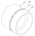
図2は本発明によるガスタービンローターの一部分を示す斜視図、図3は、図2の切断斜視図、図4は、図3の部分拡大図、図5は、本発明による第1ローター、第2ローター及び連結部材を示す部分拡大図である。
これらの図を参照すると、本実施形態によるガスタービンローター100は、外周面に圧縮機及びタービンのブレードを装着して回転駆動するガスタービンローター100であって、特定の構造の第1ローター110、第2ローター120及び連結部材130を含む構成である。
本実施形態による連結部材130は、第1ローター110及び第2ローター120を構成する素材とは熱膨張率が異なる素材で構成され、ガスタービンの始動の際に熱膨張により第1ローター110と第2ローター120との軸方向の離隔距離を変更させることにより、ガスタービンローター100の軸方向長さを効果的に調節することができ、結果としてタービンの半径方向クリアランス(clearance)を調節することができるガスタービンローター、及びこれを含むガスタービンを提供することができる。
2 is a perspective view showing a part of a gas turbine rotor according to the present invention, FIG. 3 is a cut perspective view of FIG. 2, FIG. 4 is a partially enlarged view of FIG. 3, and FIG. 5 is a first rotor according to the present invention. It is the elements on larger scale which show 2 rotors and a connection member.
Referring to these drawings, a
The connecting
以下、図面を参照して、本実施形態によるガスタービンローター100を構成する各構成について詳細に説明する。
本実施形態による第1ローター110は、一方向に所定の長さだけ延長された軸構造であり、一端部には第2ローター120の挿入部121が挿入できる挿入溝111を有する構造である。
第2ローター120は、一方向に所定の長さだけ延長された軸構造であり、一端部には第1ローター110に設けられた挿入溝111と対応する構造で所定の長さだけ延設された挿入部121を有する構造である。
また、連結部材130は、第1ローター110の挿入溝111と第2ローター120の挿入部121との間に装着され、第1ローター110と第2ローター120とを互いに結束させ、第1ローター110及び第2ローター120を構成する素材とは熱膨張率が異なる素材で構成される。
図4及び図5に示すように、第1ローター110と第2ローター120とは連結部材130によって互いに結束される。
Hereinafter, with reference to the drawings, each component constituting the
The
The
In addition, the connecting
As shown in FIGS. 4 and 5, the
具体的には、第1ローター110の一端部には、外周面に沿って一定の間隔でボルト孔112が設けられ、第1ローター110の一端部と結束される連結部材130の一側部には、ボルト孔112と対応する位置に貫通孔131が設けられている。この際、ボルト孔112と貫通孔131を用いて第1ローター110と連結部材130とが互いにボルト締結される。
また、挿入部121の一端部にも、外周面に沿って一定の間隔でボルト孔122が設けられ、挿入部121の一端部に結束される連結部材130の一側部には、ボルト孔122と対応する位置に貫通孔132が設けられる。ここでも、ボルト孔122と貫通孔132を用いて第2ローター120と連結部材130とが互いにボルト締結される。
Specifically, one end of the
Also, bolt holes 122 are provided at one end portion of the
この場合、本発明によれば、第1ローター110及び第2ローター120の一端部に設けられたボルト孔112、122、及び連結部材130に設けられた貫通孔131、132を用いて、連結部材130を第1ローター110と第2ローター120に対してそれぞれ強固かつ安定的にボルト締結することができるので、ガスタービンローター100の安定な構造を実現することができる。
本実施形態による連結部材130は、熱膨張率の異なる2種以上の素材が一定のパターンで配置されて構成できる。このとき、素材を配置するパターンは、設計者の意図に応じて適切に変更可能である。例えば、第1ローター110に連結される貫通孔131の周辺と、第2ローター120に連結される貫通孔132の周辺とを、互いに熱膨張率の異なる素材にすることにより、第1ローター110側の長さ変化と第2ローター120側の長さ変化を互いに異なるように調節することができる。もし第1ローター110側を圧縮機側とし、この第1ローター110側の連結部材130をより大きい熱膨張率の素材とする場合には、ガスタービンの始動区間で初期には圧縮機のブレードに対する半径方向クリアランスがさらに大きく調節され、逆にタービンブレードに対する半径方向クリアランスはもう少し小さく調節されるものとなる。
In this case, according to the present invention, using the bolt holes 112 and 122 provided at one end of the
The connecting
この場合、本発明によれば、用途及び順序に応じて、互いに異なる熱膨張率を有する2種以上の素材を連結部材130に適用することにより、ガスタービンの始動区間でガスタービンローターの昇温に応じてガスタービンローターの軸方向長さを局部的に互いに異なるように調節することができ、これによりタービンの半径方向クリアランス(clearance)をより能動的に調節することができるガスタービンローター、及びこれを含むガスタービンを提供することができる。
In this case, according to the present invention, the temperature of the gas turbine rotor is increased in the start-up section of the gas turbine by applying two or more kinds of materials having different thermal expansion coefficients to the connecting
一方、本実施形態による連結部材130は、図4及び図5に示すように、特定の構造の第1連結部133、延長部134及び第2連結部135を含む構成である。
具体的には、第1連結部133と第2連結部135は、延長部134の両端に一体型にそれぞれ異なる方向に折り曲げられて所定の長さだけ延長された構造である。
このとき、第1連結部133と第2連結部135とを一体に連結する延長部134は、挿入部121の外周面に対応する構造で所定の長さだけ延長された構造である。
一方、挿入溝111の内周面と挿入部121の外周面とは、延長部134の厚さTを反映して所定の距離だけ離隔することが好ましい。例えば、挿入溝111の内周面と挿入部121の外周面とが互いに離隔した距離Dは、延長部134の厚さTに対して100〜110%であり得る。
On the other hand, the
Specifically, the first connecting
At this time, the
On the other hand, the inner circumferential surface of the
挿入溝111の内周面と挿入部121の外周面とが互いに離隔した距離Dは、連結部材130を構成する素材の種類、及び熱膨張により変化する距離などを考慮して適切に変更可能である。
この場合、挿入溝111の内周面と挿入部121の外周面とが互いに離隔した距離を、延長部134の厚さTに対して特定の範囲に限定することにより、連結部材130の熱変形によるガスタービンローター100の全長の調節をより正確かつ安定的に実現することができる。
The distance D at which the inner peripheral surface of the
In this case, the distance at which the inner peripheral surface of the
一方、本実施形態に係る連結部材130は、側断面視で、第1ローター110及び第2ローター120の外径に対応する外径で形成された環状型の構造をなすことができる。
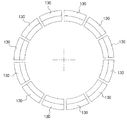
場合によって、図9に示すように、複数の断片から構成された連結部材130を用いて、第1ローター110と第2ローター120とを互いに結束させることもできる。
具体的に、複数の断片から構成された連結部材130は、2つ以上が互いに結合して、図9に示すように、側断面視で、第1ローター110及び第2ローター120の外径に対応する環状型の構造をなすことができる。このような形態の実施形態は、連結部材130を比較的小さい断片に製作することができ、ハンドリングが容易な重量で製作することができるため、ガスタービンローターを製作するにあたり、製作効率を大幅に向上させることができる。
On the other hand, the connecting
In some cases, as shown in FIG. 9, the
Specifically, two or more connecting
また、本実施形態に係る延長部134は、熱膨張率の異なる2種以上の素材を一定のパターンで配置する構成として活用するのに容易である。このとき、素材を配置するパターンは設計者の意図に応じて適切に変更可能である。
場合によって、第1ローター110と連結部材130とが互いに接触する面A、及び第2ローター120と連結部材130とが互いに接触する面Bには、熱伝達物質が塗布できる。
この場合、ガスタービンの始動区間でガスタービンローターの昇温に応じる熱伝達を効果的に誘導して、連結部材130の長さ変化を積極的に誘導することにより、ガスタービンローターの軸方向長さを容易に調節することができ、これによりタービンの半径方向クリアランス(clearance)を調節することができるガスタービンローター、及びこれを含むガスタービンを提供することができる。
Moreover, the
In some cases, a heat transfer material can be applied to the surface A where the
In this case, the axial length of the gas turbine rotor is effectively induced by inducing heat transfer according to the temperature rise of the gas turbine rotor in the gas turbine starting section and actively inducing the change in the length of the connecting
図6は本発明の他の実施形態で、第1ローター110、第2ローター120及び連結部材130を示す分解組立図、図7は図6に示された第1ローター110、第2ローター120及び連結部材130が組み立てられた様子を示す部分拡大図である。
これらの図面を参照すると、本実施形態による第1ローター110及び第2ローター120の内部には、それぞれ冷却流体が流動することができる第1流動路151、153が設けられている。また、連結部材130の内部には、第1流動路151、153に連通する第2流動路152が設けられている。このとき、第2流動路152は、連結部材130の延長方向と平行な方向に設けられることが好ましい。
好ましくは、図8に示すように、第2流動路152は、一定の距離だけ離隔して多数個が設けられ得る。
FIG. 6 is an exploded view illustrating the
Referring to these drawings,
Preferably, as shown in FIG. 8, a plurality of
この場合、また、本発明のガスタービンローターによれば、特定の構造の第1流動路151、153及び第2流動路152を備えることにより、第1流動路151、153と第2流動路152を用いて冷却空気を流動させて第1ローター110、第2ローター120及び連結部材130の熱変形による軸方向長さを容易に調節することができる。
In this case, according to the gas turbine rotor of the present invention, the
上述のように、本発明に係るガスタービンローター100を含むガスタービンを提供することができるが、本発明は、特定の構成のガスタービンローター100を備えることにより、ガスタービンの始動区間でガスタービンローターの昇温に応じてガスタービンローターの軸方向長さを調節することができ、これによりタービンの半径方向クリアランス(clearance)を調節することができるガスタービンを提供することができる。
As described above, a gas turbine including the
以上、本発明の詳細な説明は、好適な実施形態で記述したが、これに限定されるものではない。 As mentioned above, although detailed description of this invention was described by suitable embodiment, it is not limited to this.
100 ガスタービンローター
110 第1ローター
111 挿入溝
112 ボルト孔
120 第2ローター
121 挿入部
122 ボルト孔
130 連結部材
131 貫通孔
132 貫通孔
133 第1連結部
134 延長部
135 第2連結部
141、142 ボルト締結部材
151 第1流動路
152 第2流動路
153 第1流動路
A 第1ローターと連結部材とが互いに接触する面
B 第2ローターと連結部材とが互いに接触する面
D 挿入溝の内周面と挿入部の外周面とが互いに離隔した距離
T 延長部の厚さ
DESCRIPTION OF
Claims (17)
一方向に所定の長さだけ延長された軸構造であり、一端部には第2ローターの挿入部が挿入できる挿入溝を有する第1ローターと、
一方向に所定の長さだけ延長された軸構造であり、一端部には第1ローターに設けられた挿入溝と対応する構造で所定の長さだけ延設される挿入部を有する第2ローターと、
前記挿入溝と前記挿入部との間に装着され、前記第1ローターと前記第2ローターとを互いに結束させ、前記第1ローター及び前記第2ローターを構成する素材とは熱膨張率が異なる素材で構成された連結部材と、を含み、
前記第1ローター及び前記第2ローターの内部には、冷却流体が流動することが可能な第1流動路が設けられていることを特徴とするガスタービンローター。 A gas turbine rotor that is driven to rotate by mounting a compressor blade and a turbine blade on an outer peripheral surface,
A first rotor having a shaft structure extended in one direction by a predetermined length and having an insertion groove into which an insertion portion of the second rotor can be inserted at one end;
A second rotor having a shaft structure extended in one direction by a predetermined length and having an insertion portion extending at a predetermined length in one end portion with a structure corresponding to an insertion groove provided in the first rotor When,
A material that is mounted between the insertion groove and the insertion portion, binds the first rotor and the second rotor to each other, and has a coefficient of thermal expansion different from that of the material constituting the first rotor and the second rotor. and configured coupling member, only containing in,
A gas turbine rotor, wherein a first flow path through which a cooling fluid can flow is provided inside the first rotor and the second rotor.
前記第1ローターの一端部に結束される連結部材の一側部には、前記ボルト孔と対応する位置に貫通孔が設けられ、
前記ボルト孔と前記貫通孔を用いて第1ローターと連結部材とが互いにボルト締結されることを特徴とする請求項1に記載のガスタービンローター。 At one end of the first rotor, bolt holes are provided at regular intervals along the outer peripheral surface,
A through hole is provided at a position corresponding to the bolt hole on one side of the connecting member bound to one end of the first rotor.
The gas turbine rotor according to claim 1, wherein the first rotor and the connecting member are bolted to each other using the bolt holes and the through holes.
前記挿入部の一端部に結束される連結部材の一側部には、ボルト孔と対応する位置に貫通孔が設けられ、
前記ボルト孔と前記貫通孔を用いて第2ローターと連結部材とが互いにボルト締結されることを特徴とする請求項1に記載のガスタービンローター。 At one end of the insertion portion, bolt holes are provided at regular intervals along the outer peripheral surface,
A through hole is provided at a position corresponding to the bolt hole on one side of the connecting member bound to one end of the insertion part,
The gas turbine rotor according to claim 1, wherein the second rotor and the connecting member are bolted to each other using the bolt holes and the through holes.
前記第1ローターの一端部に結束される第1連結部と、
前記第2ローターの一端部に結束される第2連結部と、
前記第1連結部と前記第2連結部とを一体に連結し、前記挿入部の外周面に対応する構造で所定の長さだけ延設された延長部と、
を含むことを特徴とする請求項1に記載のガスタービンローター。 The connecting member is
A first connecting part bound to one end of the first rotor;
A second connecting portion bound to one end of the second rotor;
An extension part that integrally connects the first connection part and the second connection part, and is extended by a predetermined length in a structure corresponding to the outer peripheral surface of the insertion part;
The gas turbine rotor according to claim 1, comprising:
前記ガスタービンローターは、
一方向に所定の長さだけ延長された軸構造であり、一端部には第2ローターの端部が挿入できる挿入溝を有する第1ローターと、
一方向に所定の長さだけ延長された軸構造であり、一端部には前記第1ローターに設けられた挿入溝と対応する構造で所定の長さだけ延設された挿入部を有する第2ローターと、
前記挿入溝と前記挿入部との間に装着され、前記第1ローターと前記第2ローターとを互いに結束させ、前記第1ローター及び前記第2ローターを構成する素材とは熱膨張率が異なる素材で構成された連結部材と、を含み、
前記連結部材は、側断面視で、前記第1ローター及び前記第2ローターの外径と対応する外径で形成された環状型の構造をなすことを特徴とするガスタービン。 A gas turbine including a gas turbine rotor that is driven to rotate by mounting a blade of a compressor and a gas turbine on an outer peripheral surface,
The gas turbine rotor is
A first rotor having a shaft structure extended in one direction by a predetermined length and having an insertion groove into which an end of the second rotor can be inserted at one end;
A shaft structure extended in one direction by a predetermined length, and a second end having an insertion portion extended by a predetermined length in a structure corresponding to an insertion groove provided in the first rotor at one end. With the rotor,
A material that is mounted between the insertion groove and the insertion portion, binds the first rotor and the second rotor to each other, and has a coefficient of thermal expansion different from that of the material constituting the first rotor and the second rotor. and configured coupling member, only containing in,
The gas turbine according to claim 1, wherein the connecting member has an annular structure formed with an outer diameter corresponding to an outer diameter of the first rotor and the second rotor in a side sectional view .
前記第1ローターの一端部に結束される第1連結部と、
前記第2ローターの一端部に結束される第2連結部と、
前記第1連結部と前記第2連結部とを一体に連結し、前記挿入部の外周面に対応する構造で所定の長さだけ延設された延長部と、
を含むことを特徴とする請求項14に記載のガスタービン。 The connecting member is
A first connecting part bound to one end of the first rotor;
A second connecting portion bound to one end of the second rotor;
An extension part that integrally connects the first connection part and the second connection part, and is extended by a predetermined length in a structure corresponding to the outer peripheral surface of the insertion part;
The gas turbine according to claim 14 , comprising:
15. The connection member according to claim 14 , wherein two or more of the connecting members are coupled to each other and have an annular structure corresponding to the outer diameters of the first rotor and the second rotor in a side sectional view. gas turbine.
Applications Claiming Priority (2)
| Application Number | Priority Date | Filing Date | Title |
|---|---|---|---|
| KR10-2017-0055165 | 2017-04-28 | ||
| KR1020170055165A KR101872808B1 (en) | 2017-04-28 | 2017-04-28 | Gas Turbine Rotor Having Control Structure Of Axial Clearance, And Gas Turbine Having The Same |
Publications (2)
| Publication Number | Publication Date |
|---|---|
| JP2018189080A JP2018189080A (en) | 2018-11-29 |
| JP6453407B2 true JP6453407B2 (en) | 2019-01-16 |
Family
ID=59966654
Family Applications (1)
| Application Number | Title | Priority Date | Filing Date |
|---|---|---|---|
| JP2017180277A Active JP6453407B2 (en) | 2017-04-28 | 2017-09-20 | Gas turbine rotor and gas turbine |
Country Status (4)
| Country | Link |
|---|---|
| US (2) | US10612417B2 (en) |
| EP (1) | EP3396106B1 (en) |
| JP (1) | JP6453407B2 (en) |
| KR (1) | KR101872808B1 (en) |
Family Cites Families (30)
| Publication number | Priority date | Publication date | Assignee | Title |
|---|---|---|---|---|
| BE469282A (en) * | 1945-11-20 | |||
| FR1012335A (en) * | 1949-07-13 | 1952-07-08 | Hispano Suiza Sa | Improvements made to machines, especially axial compressors, with rotor equipped with several blades arranged in tandem |
| GB969579A (en) * | 1962-11-09 | 1964-09-09 | Rolls Royce | Gas turbine engine |
| US3304052A (en) * | 1965-03-30 | 1967-02-14 | Westinghouse Electric Corp | Rotor structure for an elastic fluid utilizing machine |
| US3597110A (en) * | 1969-10-23 | 1971-08-03 | Gen Electric | Joint construction |
| JPS5769116A (en) * | 1980-10-17 | 1982-04-27 | Toyo Eng Corp | Flexible coupling |
| US4478593A (en) * | 1981-06-08 | 1984-10-23 | Gordon Brown | Coupling of unrelated engine and transmission |
| JPS58201040A (en) * | 1982-05-19 | 1983-11-22 | Hitachi Ltd | Device for diagnosing fault of composite cycle plant shaft |
| JPS59169480U (en) * | 1983-04-28 | 1984-11-13 | 株式会社日立製作所 | Expansion joint for low pressure cabin |
| DE3407275A1 (en) | 1984-02-28 | 1985-08-29 | Kraftwerk Union AG, 4330 Mülheim | DEVICE ON A ROTATING MACHINE FOR HEAT-MOVABLE AND SEALING COUPLING OF TWO CONCENTRIC SHAFTS |
| DE3535511A1 (en) * | 1984-10-06 | 1986-04-17 | Ngk Spark Plug Co., Ltd., Nagoya, Aichi | Connecting arrangement between a ceramic shaft and a metal shaft |
| JPS631890A (en) * | 1986-02-14 | 1988-01-06 | 株式会社日立製作所 | Expansion pipe joint |
| DE3815977A1 (en) * | 1988-05-10 | 1989-11-30 | Mtu Muenchen Gmbh | INTERMEDIATE FILM FOR JOINING MACHINE COMPONENTS HAZARDOUS TO FRICTION |
| US4836750A (en) * | 1988-06-15 | 1989-06-06 | Pratt & Whitney Canada Inc. | Rotor assembly |
| US5203441A (en) * | 1992-06-01 | 1993-04-20 | Eaton Corporation | Adaptor for use in a flywheel and transmission assembly |
| JP3621523B2 (en) * | 1996-09-25 | 2005-02-16 | 株式会社東芝 | Gas turbine rotor blade cooling system |
| US6283712B1 (en) * | 1999-09-07 | 2001-09-04 | General Electric Company | Cooling air supply through bolted flange assembly |
| US6364634B1 (en) * | 2000-09-29 | 2002-04-02 | General Motors Corporation | Turbocharger rotor with alignment couplings |
| US7255538B2 (en) * | 2005-02-09 | 2007-08-14 | Hamilton Sundstrand Corporation | Shrink-fit stress coupling for a shaft of differing materials |
| EP1744016A1 (en) * | 2005-07-11 | 2007-01-17 | Siemens Aktiengesellschaft | Hot gas conducting cover element, shaft protection shroud and gas turbine |
| US7870742B2 (en) * | 2006-11-10 | 2011-01-18 | General Electric Company | Interstage cooled turbine engine |
| US7874156B2 (en) * | 2007-03-29 | 2011-01-25 | General Electric Company | Methods and apparatus for heating a fluid |
| US8251643B2 (en) * | 2009-09-23 | 2012-08-28 | General Electric Company | Steam turbine having rotor with cavities |
| EP2333239A1 (en) * | 2009-12-08 | 2011-06-15 | Alstom Technology Ltd | Manufacture method for a steam turbine rotor and corresponding rotor |
| JP5822496B2 (en) | 2011-03-23 | 2015-11-24 | 三菱日立パワーシステムズ株式会社 | Turbine rotor and method of manufacturing turbine rotor |
| GB201200403D0 (en) | 2012-01-10 | 2012-02-22 | Napier Turbochargers Ltd | Connector |
| AU2013311950B2 (en) * | 2012-09-04 | 2017-04-13 | Hackforth Gmbh | Shaft made of fibre composite material with fireproof bulkhead feedthrough |
| EP2933432A1 (en) * | 2014-04-15 | 2015-10-21 | Siemens Aktiengesellschaft | Rotor with axially secured support ring |
| US20150345504A1 (en) * | 2014-05-29 | 2015-12-03 | Siemens Energy, Inc. | Method for forming a coating matrix on a shaft and disk assembly for a turbine |
| KR101783906B1 (en) | 2015-07-30 | 2017-10-10 | 정현욱 | Rotor assembly of gas turbine engine |
-
2017
- 2017-04-28 KR KR1020170055165A patent/KR101872808B1/en active IP Right Grant
- 2017-09-20 JP JP2017180277A patent/JP6453407B2/en active Active
- 2017-09-25 US US15/714,126 patent/US10612417B2/en active Active
- 2017-09-25 EP EP17192933.4A patent/EP3396106B1/en active Active
-
2020
- 2020-02-24 US US16/799,794 patent/US11242771B2/en active Active
Also Published As
| Publication number | Publication date |
|---|---|
| EP3396106A1 (en) | 2018-10-31 |
| US10612417B2 (en) | 2020-04-07 |
| KR101872808B1 (en) | 2018-06-29 |
| US20180313229A1 (en) | 2018-11-01 |
| US20200248590A1 (en) | 2020-08-06 |
| JP2018189080A (en) | 2018-11-29 |
| US11242771B2 (en) | 2022-02-08 |
| EP3396106B1 (en) | 2019-11-06 |
Similar Documents
| Publication | Publication Date | Title |
|---|---|---|
| EP2230382B1 (en) | Gas turbine rotor stage | |
| JP6818423B2 (en) | Shroud assembly and shroud for gas turbine engines | |
| EP2914816B1 (en) | Blade outer air seal | |
| EP2246623A1 (en) | Cooled hybrid structure for gas turbine engine and method for the fabrication thereof | |
| JP2017187019A (en) | Airfoil assembly with leading edge element | |
| US10352177B2 (en) | Airfoil having impingement openings | |
| JP2010174887A (en) | Gas turbine engine assembly and method of assembling the same | |
| JP2016194297A (en) | Turbine frame and airfoil for turbine frame | |
| JP5842382B2 (en) | Gas turbine engine | |
| CA2944464A1 (en) | Turbine blade | |
| US20180328190A1 (en) | Gas turbine engine with film holes | |
| CA2944392A1 (en) | Turbine blade | |
| CN107035414B (en) | Method and system for separable blade platform retention clip | |
| CA2957481A1 (en) | Airfoil having crossover holes | |
| EP2354462A2 (en) | Compressor | |
| CA2948253A1 (en) | Engine component with film cooling | |
| US10982547B2 (en) | Compressor having reinforcing disk, and gas turbine having same | |
| JP2004028097A (en) | Cooling device and manufacturing method of turbine blade wall | |
| JP2017082766A (en) | Ceramic matrix composite ring shroud retention methods, and cmc pin head | |
| JP6453407B2 (en) | Gas turbine rotor and gas turbine | |
| JP5552281B2 (en) | Method for clocking turbine airfoils | |
| JP2017150477A (en) | Accelerator insert for gas turbine engine airfoil | |
| JP2017141823A (en) | Thermal stress relief of component | |
| JP5662672B2 (en) | Equipment related to turbine airfoil cooling apertures | |
| EP3244006B1 (en) | A shaft and a turbomachine |
Legal Events
| Date | Code | Title | Description |
|---|---|---|---|
| A521 | Request for written amendment filed |
Free format text: JAPANESE INTERMEDIATE CODE: A523 Effective date: 20181011 |
|
| TRDD | Decision of grant or rejection written | ||
| A01 | Written decision to grant a patent or to grant a registration (utility model) |
Free format text: JAPANESE INTERMEDIATE CODE: A01 Effective date: 20181204 |
|
| A61 | First payment of annual fees (during grant procedure) |
Free format text: JAPANESE INTERMEDIATE CODE: A61 Effective date: 20181212 |
|
| R150 | Certificate of patent or registration of utility model |
Ref document number: 6453407 Country of ref document: JP Free format text: JAPANESE INTERMEDIATE CODE: R150 |
|
| R250 | Receipt of annual fees |
Free format text: JAPANESE INTERMEDIATE CODE: R250 |
|
| R250 | Receipt of annual fees |
Free format text: JAPANESE INTERMEDIATE CODE: R250 |
|
| R250 | Receipt of annual fees |
Free format text: JAPANESE INTERMEDIATE CODE: R250 |