JP6452628B2 - Method and apparatus for reworking structures - Google Patents
Method and apparatus for reworking structures Download PDFInfo
- Publication number
- JP6452628B2 JP6452628B2 JP2015556943A JP2015556943A JP6452628B2 JP 6452628 B2 JP6452628 B2 JP 6452628B2 JP 2015556943 A JP2015556943 A JP 2015556943A JP 2015556943 A JP2015556943 A JP 2015556943A JP 6452628 B2 JP6452628 B2 JP 6452628B2
- Authority
- JP
- Japan
- Prior art keywords
- patch
- resin
- dry fiber
- fiber patch
- vacuum
- Prior art date
- Legal status (The legal status is an assumption and is not a legal conclusion. Google has not performed a legal analysis and makes no representation as to the accuracy of the status listed.)
- Active
Links
- 238000000034 method Methods 0.000 title claims description 79
- 239000011347 resin Substances 0.000 claims description 169
- 229920005989 resin Polymers 0.000 claims description 169
- 239000000835 fiber Substances 0.000 claims description 122
- 239000002131 composite material Substances 0.000 claims description 27
- 238000002347 injection Methods 0.000 claims description 20
- 239000007924 injection Substances 0.000 claims description 20
- 238000009826 distribution Methods 0.000 claims description 15
- 239000000853 adhesive Substances 0.000 claims description 7
- 230000001070 adhesive effect Effects 0.000 claims description 7
- 238000007789 sealing Methods 0.000 claims description 7
- 230000003014 reinforcing effect Effects 0.000 claims description 5
- 238000003780 insertion Methods 0.000 claims description 3
- 230000037431 insertion Effects 0.000 claims description 3
- 239000012530 fluid Substances 0.000 description 9
- 238000004519 manufacturing process Methods 0.000 description 9
- 238000012423 maintenance Methods 0.000 description 8
- 239000000463 material Substances 0.000 description 6
- 230000008569 process Effects 0.000 description 6
- 230000008439 repair process Effects 0.000 description 6
- 239000000565 sealant Substances 0.000 description 6
- 230000006835 compression Effects 0.000 description 5
- 238000007906 compression Methods 0.000 description 5
- 238000010586 diagram Methods 0.000 description 5
- 230000035515 penetration Effects 0.000 description 5
- 230000007547 defect Effects 0.000 description 4
- 238000013461 design Methods 0.000 description 3
- 210000001503 joint Anatomy 0.000 description 3
- 230000002787 reinforcement Effects 0.000 description 3
- 238000009756 wet lay-up Methods 0.000 description 3
- 230000008878 coupling Effects 0.000 description 2
- 238000010168 coupling process Methods 0.000 description 2
- 238000005859 coupling reaction Methods 0.000 description 2
- 125000004122 cyclic group Chemical group 0.000 description 2
- 238000005516 engineering process Methods 0.000 description 2
- 239000011152 fibreglass Substances 0.000 description 2
- 238000012986 modification Methods 0.000 description 2
- 230000004048 modification Effects 0.000 description 2
- 239000004677 Nylon Substances 0.000 description 1
- 230000002411 adverse Effects 0.000 description 1
- 238000013459 approach Methods 0.000 description 1
- 238000013475 authorization Methods 0.000 description 1
- CJPQIRJHIZUAQP-MRXNPFEDSA-N benalaxyl-M Chemical compound CC=1C=CC=C(C)C=1N([C@H](C)C(=O)OC)C(=O)CC1=CC=CC=C1 CJPQIRJHIZUAQP-MRXNPFEDSA-N 0.000 description 1
- -1 but not limited to Substances 0.000 description 1
- 239000000919 ceramic Substances 0.000 description 1
- 238000004140 cleaning Methods 0.000 description 1
- 230000000694 effects Effects 0.000 description 1
- 230000002708 enhancing effect Effects 0.000 description 1
- 230000007613 environmental effect Effects 0.000 description 1
- 239000004744 fabric Substances 0.000 description 1
- 238000009787 hand lay-up Methods 0.000 description 1
- 238000001802 infusion Methods 0.000 description 1
- 230000010354 integration Effects 0.000 description 1
- 230000007246 mechanism Effects 0.000 description 1
- 239000002184 metal Substances 0.000 description 1
- 229910052751 metal Inorganic materials 0.000 description 1
- 239000002905 metal composite material Substances 0.000 description 1
- 150000002739 metals Chemical class 0.000 description 1
- 229920001778 nylon Polymers 0.000 description 1
- 230000000149 penetrating effect Effects 0.000 description 1
- 238000009419 refurbishment Methods 0.000 description 1
- 238000007634 remodeling Methods 0.000 description 1
- 230000003252 repetitive effect Effects 0.000 description 1
- 238000000926 separation method Methods 0.000 description 1
- 238000005728 strengthening Methods 0.000 description 1
- 238000012546 transfer Methods 0.000 description 1
- 239000002759 woven fabric Substances 0.000 description 1
Images


Classifications
-
- B—PERFORMING OPERATIONS; TRANSPORTING
- B29—WORKING OF PLASTICS; WORKING OF SUBSTANCES IN A PLASTIC STATE IN GENERAL
- B29C—SHAPING OR JOINING OF PLASTICS; SHAPING OF MATERIAL IN A PLASTIC STATE, NOT OTHERWISE PROVIDED FOR; AFTER-TREATMENT OF THE SHAPED PRODUCTS, e.g. REPAIRING
- B29C70/00—Shaping composites, i.e. plastics material comprising reinforcements, fillers or preformed parts, e.g. inserts
- B29C70/04—Shaping composites, i.e. plastics material comprising reinforcements, fillers or preformed parts, e.g. inserts comprising reinforcements only, e.g. self-reinforcing plastics
- B29C70/28—Shaping operations therefor
- B29C70/54—Component parts, details or accessories; Auxiliary operations, e.g. feeding or storage of prepregs or SMC after impregnation or during ageing
- B29C70/544—Details of vacuum bags, e.g. materials or shape
-
- B—PERFORMING OPERATIONS; TRANSPORTING
- B32—LAYERED PRODUCTS
- B32B—LAYERED PRODUCTS, i.e. PRODUCTS BUILT-UP OF STRATA OF FLAT OR NON-FLAT, e.g. CELLULAR OR HONEYCOMB, FORM
- B32B38/00—Ancillary operations in connection with laminating processes
- B32B38/08—Impregnating
-
- B—PERFORMING OPERATIONS; TRANSPORTING
- B29—WORKING OF PLASTICS; WORKING OF SUBSTANCES IN A PLASTIC STATE IN GENERAL
- B29C—SHAPING OR JOINING OF PLASTICS; SHAPING OF MATERIAL IN A PLASTIC STATE, NOT OTHERWISE PROVIDED FOR; AFTER-TREATMENT OF THE SHAPED PRODUCTS, e.g. REPAIRING
- B29C70/00—Shaping composites, i.e. plastics material comprising reinforcements, fillers or preformed parts, e.g. inserts
- B29C70/04—Shaping composites, i.e. plastics material comprising reinforcements, fillers or preformed parts, e.g. inserts comprising reinforcements only, e.g. self-reinforcing plastics
- B29C70/28—Shaping operations therefor
- B29C70/40—Shaping or impregnating by compression not applied
- B29C70/42—Shaping or impregnating by compression not applied for producing articles of definite length, i.e. discrete articles
- B29C70/44—Shaping or impregnating by compression not applied for producing articles of definite length, i.e. discrete articles using isostatic pressure, e.g. pressure difference-moulding, vacuum bag-moulding, autoclave-moulding or expanding rubber-moulding
- B29C70/443—Shaping or impregnating by compression not applied for producing articles of definite length, i.e. discrete articles using isostatic pressure, e.g. pressure difference-moulding, vacuum bag-moulding, autoclave-moulding or expanding rubber-moulding and impregnating by vacuum or injection
-
- B—PERFORMING OPERATIONS; TRANSPORTING
- B29—WORKING OF PLASTICS; WORKING OF SUBSTANCES IN A PLASTIC STATE IN GENERAL
- B29C—SHAPING OR JOINING OF PLASTICS; SHAPING OF MATERIAL IN A PLASTIC STATE, NOT OTHERWISE PROVIDED FOR; AFTER-TREATMENT OF THE SHAPED PRODUCTS, e.g. REPAIRING
- B29C73/00—Repairing of articles made from plastics or substances in a plastic state, e.g. of articles shaped or produced by using techniques covered by this subclass or subclass B29D
- B29C73/04—Repairing of articles made from plastics or substances in a plastic state, e.g. of articles shaped or produced by using techniques covered by this subclass or subclass B29D using preformed elements
- B29C73/10—Repairing of articles made from plastics or substances in a plastic state, e.g. of articles shaped or produced by using techniques covered by this subclass or subclass B29D using preformed elements using patches sealing on the surface of the article
- B29C73/12—Apparatus therefor, e.g. for applying
-
- Y—GENERAL TAGGING OF NEW TECHNOLOGICAL DEVELOPMENTS; GENERAL TAGGING OF CROSS-SECTIONAL TECHNOLOGIES SPANNING OVER SEVERAL SECTIONS OF THE IPC; TECHNICAL SUBJECTS COVERED BY FORMER USPC CROSS-REFERENCE ART COLLECTIONS [XRACs] AND DIGESTS
- Y10—TECHNICAL SUBJECTS COVERED BY FORMER USPC
- Y10T—TECHNICAL SUBJECTS COVERED BY FORMER US CLASSIFICATION
- Y10T156/00—Adhesive bonding and miscellaneous chemical manufacture
- Y10T156/17—Surface bonding means and/or assemblymeans with work feeding or handling means
- Y10T156/1798—Surface bonding means and/or assemblymeans with work feeding or handling means with liquid adhesive or adhesive activator applying means
Landscapes
- Engineering & Computer Science (AREA)
- Mechanical Engineering (AREA)
- Chemical & Material Sciences (AREA)
- Composite Materials (AREA)
- Casting Or Compression Moulding Of Plastics Or The Like (AREA)
- Moulding By Coating Moulds (AREA)
- Reinforced Plastic Materials (AREA)
Description
本開示は、概して、構造、特に複合材料を再加工及び/又は強化するための機器並びにプロセスに関し、さらに具体的には、構造をその一側面から再加工するための方法並びに装置を扱う。 The present disclosure relates generally to equipment and processes for reworking and / or strengthening structures, particularly composite materials, and more specifically, methods and apparatus for reworking structures from one aspect thereof.
複合構造は、構造を設計許容度内に収める、又は局所を強化するために再加工を必要とし得る一つ又は複数の不具合を含む局所を有することがある。 A composite structure may have a locality that includes one or more defects that may require rework to keep the structure within design tolerances or strengthen the locality.
構造の局所を再加工するための一つの技術は、その局所全域にパッチを機械的に留めることを含むが、留め具は、航空機の重量及び/又は航空機の抗力を増加させることがあり、さらに用途によっては外見的に好ましくないこともある。 One technique for reworking a local area of the structure involves mechanically fastening a patch across the local area, but the fastener may increase aircraft weight and / or aircraft drag, and Depending on the application, it may be undesirable in appearance.
同様に、接着された再加工パッチはまた、休み装置機構(arrestment mechanism)を形成する補助的荷重経路を提供し、不具合が大きくなるのを制限するために、機械的留め具の使用を必要とすることもある。 Similarly, the glued rework patch also provides an auxiliary load path that forms an arrest mechanism and requires the use of mechanical fasteners to limit the failure. Sometimes.
湿式レイアップ技術と呼ばれる、構造を再加工するためのさらに別の技術は、織物又は編物などの繊維強化材を含む湿式プライのハンドレイアップ、及びレイアップされる間に湿式樹脂をプライに適用することを含む。湿式レイアップ技術は、空気の封じ込めをパッチ内に生じさせ得、これにより再加工されるエリアに好ましくない空隙が形成され得る。これらの空隙は、再加工されるエリアに好ましくない影響を及ぼすことがあり、再加工されるエリアが仕様を満たしていることの検証を困難にすることがある。湿式レイアップ技術はまた、大きな労働力を要し、修理技術者が湿式樹脂に接近しなければならず、更には、過度の洗浄活動を要求することにもなり得る。 Yet another technique for reworking the structure, called wet layup technology, is the hand layup of wet plies containing fiber reinforcements such as woven or knitted fabric, and applying wet resin to the plies while being laid up Including doing. Wet layup techniques can cause air containment within the patch, which can create undesirable voids in the reworked area. These voids can adversely affect the reworked area and can make it difficult to verify that the reworked area meets specifications. Wet lay-up technology also requires a large labor force, repair technicians must approach the wet resin, and may require excessive cleaning activities.
用途によっては、先述の問題は、乾燥繊維プリフォームパッチの樹脂注入を用いることにより回避され得る。乾燥繊維プリフォームをスカーフ継ぎで接合された外板などの構造上に配置した後に、樹脂が外板外側から繊維プリフォームに注入されるのに対し、余分な樹脂が外板内側のプリフォームから引き抜かれている。この技術は、有効である間、構造の両側、例えば、外板の内側及び外側への物理的なアクセスを必要とする。結果として、この技術は、構造の一側面へのアクセスが困難又は不可能である用途での使用には適していないこともある。 Depending on the application, the above mentioned problems can be avoided by using resin injection of dry fiber preform patches. After placing the dry fiber preform on a structure such as an outer plate joined with a scarf joint, the resin is injected into the fiber preform from the outside of the outer plate, whereas excess resin is injected from the preform inside the outer plate. It has been pulled out. While effective, this technique requires physical access to both sides of the structure, for example, the inside and outside of the skin. As a result, this technique may not be suitable for use in applications where access to one aspect of the structure is difficult or impossible.
したがって、空気の封じ込めに起因する空隙を削減又は排除する構造、特に複合材料を再加工するための方法及び装置が必要とされる。また、構造の一側面のみへのアクセスが可能である用途での使用に適合され得る先述の方法及び装置も必要である。 Accordingly, there is a need for structures and methods and apparatus for reworking composite materials that reduce or eliminate voids due to air containment, particularly composite materials. There is also a need for the aforementioned methods and apparatus that can be adapted for use in applications where only one aspect of the structure is accessible.
開示される実施形態は、構造の一側面のみから、例えば、航空機外板の外側から、取り付け注入することができる乾燥繊維プリフォームパッチの樹脂注入を使用して構造を再加工するための方法及び装置を提供する。樹脂注入プロセス中のパッチ内の高圧エリアは、実質的に排除され、これにより再加工されるエリアの空気の封じ込め及び関連する空隙が回避される。実施形態は、労働力を削減し、人の湿式樹脂への接触の必要性を回避し、荷重を運ぶ複合構造部材の再加工を可能にする。開示される方法は、制御された気圧樹脂注入を使用して実施され得、構造の空隙を最適化することができる。 The disclosed embodiments provide a method for reworking a structure using resin injection of a dry fiber preform patch that can be installed and injected from only one side of the structure, eg, from the outside of an aircraft skin. Providing equipment. The high pressure area in the patch during the resin injection process is substantially eliminated, thereby avoiding air containment and associated voids in the reworked area. Embodiments reduce labor, avoid the need for human contact with wet resin, and allow reworking of composite structural members that carry loads. The disclosed method can be implemented using controlled atmospheric pressure resin injection to optimize the voids of the structure.
一つの開示される実施形態によれば、構造のエリアを再加工する方法が提供される。方法は、パッチを構造上に配置することと、真空源をパッチの外側からパッチに挿入することと、入ってくる高圧樹脂を、パッチを通してパッチの内側に押し込む非常に低圧のエリアを作り出すために、真空源を使用することとを含む。パッチは、乾燥繊維パッチであり得る。方法は、真空バッグをパッチの外側上方に配置することと、バッグを排気して乾燥繊維パッチを圧縮することと、次いで、樹脂をパッチの外側からパッチに流し込むことにより、パッチに樹脂を注入することとを更に含み得る。方法はまた、パッチに樹脂が注入された後に、真空源をパッチから除去することを含み得る。方法は、構造の厚さを部分的に通ってスカーフを形成することを更に含み得、パッチを構造上に配置することは、スカーフの底に対してパッチの内側を配置することを含む。真空源を挿入することは、中空針を繊維パッチの最も厚い部分を通って実質的にスカーフの底まで挿入することを含む。真空源を挿入することは、中空針を真空バッグを通して挿入することと、中空針と真空バッグとの間に実質的に真空気密のシールを形成することを更に含む。真空源を繊維パッチから除去することは、中空針を繊維パッチから及び真空バッグから引き抜くことと、中空針による真空バッグの貫通から生じる真空バッグの穴を密閉することとを含む。方法は、針が繊維パッチから引き抜かれ、バッグが密閉された後に、真空バッグを排気することにより、樹脂が注入されたパッチを圧縮することを更に含み得る。パッチに樹脂を注入することは、差分樹脂圧(differential resin pressure)を使用して実行される。樹脂を繊維パッチの外側から繊維パッチに流し込むことは、樹脂分配管を、真空バッグ下方の繊維パッチの外側に配置することと、樹脂を樹脂分配管に供給することとを含む。 According to one disclosed embodiment, a method for reworking an area of a structure is provided. The method involves placing the patch on the structure, inserting a vacuum source into the patch from the outside of the patch, and creating a very low pressure area where the incoming high pressure resin is forced through the patch and into the patch. Using a vacuum source. The patch can be a dry fiber patch. The method injects the resin into the patch by placing a vacuum bag over the outside of the patch, evacuating the bag to compress the dried fiber patch, and then pouring the resin into the patch from the outside of the patch Can further include. The method can also include removing the vacuum source from the patch after the resin is injected into the patch. The method may further include forming a scarf partially through the thickness of the structure, and disposing the patch on the structure includes disposing the inside of the patch relative to the bottom of the scarf. Inserting the vacuum source includes inserting the hollow needle through the thickest portion of the fiber patch and substantially to the bottom of the scarf. Inserting the vacuum source further includes inserting the hollow needle through the vacuum bag and forming a substantially vacuum tight seal between the hollow needle and the vacuum bag. Removing the vacuum source from the fiber patch includes withdrawing the hollow needle from the fiber patch and from the vacuum bag and sealing the vacuum bag hole resulting from the penetration of the vacuum bag by the hollow needle. The method may further include compressing the resin-injected patch by evacuating the vacuum bag after the needle is withdrawn from the fiber patch and the bag is sealed. Injecting resin into the patch is performed using a differential resin pressure. Pouring the resin from the outside of the fiber patch into the fiber patch includes disposing the resin distribution pipe outside the fiber patch below the vacuum bag and supplying the resin to the resin distribution pipe.
別の開示される実施形態によれば、構造のエリアを再加工する方法であって、構造の厚さを部分的に通ってスカーフを形成することと、内側及び外側を有する乾燥繊維パッチを製造することと、スカーフの底で構造に対してパッチの内側を配置することを含む、パッチをスカーフ内部に取り付けることとを含む方法が提供される。方法はまた、繊維パッチ上方に真空バッグを取り付けることと、パッチの外側からパッチを通して真空デバイスを挿入することと、バッグを排気して乾燥繊維パッチを圧縮することと、次いでパッチに樹脂を注入することと、樹脂をパッチを通してパッチの内側に押し込むために真空デバイスを使用することとを含む。方法は、パッチに樹脂が注入された後に、真空源をパッチから除去することを更に含む。パッチを通して真空デバイスを挿入することは、真空針の先端がパッチの厚さ部分を実質的に貫通するまで、真空バッグ及びパッチを通して中空針を挿入することを含む。方法は、真空バッグと真空針との間に実質的に真空気密のシールを形成することと、パッチに樹脂が注入された後に、パッチ及びバッグから真空針を引き抜くこととを更に含み得る。方法はまた、真空バッグから真空針を引き抜くことから生じる真空バッグの穴を密閉することを含み得る。パッチに樹脂を注入することは、パッチの外側の制御された気圧下で樹脂を案内することにより実行される。樹脂を案内することは、螺旋状に巻き付けられた管(spiral wrap tube)をパッチの外側の外縁周囲に配置することと、螺旋状に巻き付けられた管を、部分気圧(partial atmospheric pressure)で螺旋状に巻き付けられた管に樹脂を供給するように適合される樹脂のリザーバと連結させることとを含む。方法は、余分な樹脂を、中空針の端部を通してパッチから除去することを更に含み得る。 According to another disclosed embodiment, a method for reworking an area of a structure, wherein a scarf is formed partially through the thickness of the structure and a dry fiber patch having an inner side and an outer side is produced. And attaching the patch to the interior of the scarf, including placing the inside of the patch relative to the structure at the bottom of the scarf. The method also attaches a vacuum bag over the fiber patch, inserts a vacuum device through the patch from the outside of the patch, evacuates the bag to compress the dry fiber patch, and then injects resin into the patch And using a vacuum device to push the resin through the patch and inside the patch. The method further includes removing the vacuum source from the patch after the resin is injected into the patch. Inserting the vacuum device through the patch includes inserting the hollow needle through the vacuum bag and patch until the tip of the vacuum needle substantially penetrates the thickness portion of the patch. The method may further include forming a substantially vacuum tight seal between the vacuum bag and the vacuum needle and withdrawing the vacuum needle from the patch and bag after the resin has been injected into the patch. The method may also include sealing a vacuum bag hole resulting from withdrawing the vacuum needle from the vacuum bag. Injecting resin into the patch is performed by guiding the resin under controlled atmospheric pressure outside the patch. Guide the resin by placing a spiral wrap tube around the outer edge of the patch and spiraling the spirally wound tube at a partial atmospheric pressure. Connecting to a reservoir of resin adapted to supply the resin to a tube wound in a shape. The method can further include removing excess resin from the patch through the end of the hollow needle.
更に別の実施形態によれば、複合材構造のエリアをその一側面のみから再加工する方法が提供される。方法は、スカーフを複合材構造の一側面に形成することと、繊維パッチをスカーフに取り付けることと、パッチの内側を構造に接触するように配置することを含むことと、真空バッグをパッチ上方に取り付けることと、中空針の先端がパッチの内側に近接するまで、中空針を真空バッグを通してパッチまで挿入することとを含む。方法は、中空針と真空バッグとの間にシールを形成することと、中空針を真空リザーバと連結することと、樹脂をパッチの外側に流し込むことによりパッチに樹脂を注入することと、樹脂を繊維パッチの内側に押し込むために中空針及び真空リザーバを使用することと、繊維パッチの余分な樹脂を中空針を通して除去することとを更に含む。方法はまた、パッチに樹脂が注入された後に、中空針をパッチから除去することを含む。パッチは、最大の厚さのエリアを有し得る。中空針を挿入することは、中空針の先端を繊維パッチの最大の厚さのエリアを通すことにより実行される。方法は、中空針をパッチ及び真空バッグから引き抜くことと、中空針を真空バッグから引き抜くことにより生じる真空バッグの穴を密閉することとを更に含む。樹脂をパッチの外側に流し込むことと、樹脂を繊維パッチの内側に押し込むために中空針及び真空リザーバを使用することとは、制御された部分気圧の樹脂注入を使用して実行され得る。 According to yet another embodiment, a method is provided for reworking an area of a composite structure from only one side thereof. The method includes forming a scarf on one side of the composite structure, attaching a fiber patch to the scarf, placing the inside of the patch in contact with the structure, and placing a vacuum bag over the patch. Attaching and inserting the hollow needle through the vacuum bag into the patch until the tip of the hollow needle is in close proximity to the inside of the patch. The method includes forming a seal between the hollow needle and the vacuum bag, coupling the hollow needle to a vacuum reservoir, injecting resin into the patch by pouring the resin outside the patch, The method further includes using a hollow needle and vacuum reservoir to push inside the fiber patch and removing excess resin from the fiber patch through the hollow needle. The method also includes removing the hollow needle from the patch after the resin is injected into the patch. The patch may have a maximum thickness area. Inserting the hollow needle is performed by passing the tip of the hollow needle through the area of maximum thickness of the fiber patch. The method further includes withdrawing the hollow needle from the patch and vacuum bag and sealing the vacuum bag hole that results from withdrawing the hollow needle from the vacuum bag. Pouring the resin outside the patch and using a hollow needle and vacuum reservoir to push the resin inside the fiber patch can be performed using controlled partial pressure resin injection.
更なる実施形態によれば、内側及び外側を有する乾燥繊維パッチの樹脂注入を使用して、複合構造のエリアを再加工するための装置が提供される。装置は、パッチを圧縮するための、パッチの外側上方に配置されるように適合される真空バッグと、真空バッグを貫通し、パッチの厚さを通して下に延びるように適合される中空針とを備える。装置はまた、中空針と真空バッグとの間の真空シールと、パッチの内側で真空を生成するための、中空針と連結される真空ラインとを備える。装置は、制御された部分気圧で繊維パッチの外側に樹脂を供給するための樹脂のリザーバと、パッチの内側で真空を生成し、余分な樹脂をパッチから取り除くための、中空針と連結される真空源とを更に備え得る。 According to a further embodiment, an apparatus is provided for reworking an area of a composite structure using resin injection of a dry fiber patch having an inner side and an outer side. The device includes a vacuum bag adapted to be positioned over the outside of the patch for compressing the patch, and a hollow needle adapted to extend through the vacuum bag and down through the thickness of the patch. Prepare. The apparatus also includes a vacuum seal between the hollow needle and the vacuum bag, and a vacuum line coupled to the hollow needle for generating a vacuum inside the patch. The device is coupled with a resin reservoir for supplying resin to the outside of the fiber patch at a controlled partial pressure, and a hollow needle for creating a vacuum inside the patch and removing excess resin from the patch. And a vacuum source.
要するに、本発明の一つの態様によれば、構造のエリアを再加工する方法であって、パッチを構造上に配置することと、真空源をパッチの外側からパッチに挿入することと、樹脂をパッチを通してパッチの内側に押し込むために、真空源を使用することとを含む方法が提供される。 In summary, according to one aspect of the present invention, a method for reworking an area of a structure comprising placing a patch on the structure, inserting a vacuum source into the patch from outside the patch, Using a vacuum source to push the patch through the patch and into the inside of the patch is provided.
有利には、パッチを構造上に配置することは、乾燥パッチを構造上に配置することと、乾燥繊維パッチと構造との間に接着強化層を配置することとを含む方法。 Advantageously, disposing the patch on the structure includes disposing the dry patch on the structure and disposing an adhesion enhancing layer between the dry fiber patch and the structure.
有利には、真空バッグをパッチの外側上方に配置することと、樹脂をパッチの外側からパッチに流し込むことにより、パッチに樹脂を注入することとを更に含む方法。 Advantageously, the method further comprises placing a vacuum bag above the outside of the patch and injecting the resin into the patch by pouring the resin into the patch from the outside of the patch.
有利には、パッチに樹脂が注入された後に、真空源をパッチから除去することを更に含む方法。 Advantageously, the method further comprises removing the vacuum source from the patch after the resin has been injected into the patch.
有利には、構造の厚さを部分的に通ってスカーフを形成することを更に含む方法であって、繊維パッチを構造上に配置することは、スカーフの底に対してパッチの内側を配置することを含み、真空源を挿入することは、中空針をパッチの最も厚い部分を通って実質的にスカーフの底まで挿入することを含む。 Advantageously, the method further comprises forming the scarf partially through the thickness of the structure, wherein placing the fiber patch on the structure places the inside of the patch relative to the bottom of the scarf And inserting the vacuum source includes inserting the hollow needle through the thickest portion of the patch substantially to the bottom of the scarf.
有利には、真空源を挿入することは、中空針を真空バッグを通して挿入することと、中空針と真空バッグとの間に実質的に真空気密のシールを形成することを更に含む方法。 Advantageously, inserting the vacuum source further comprises inserting the hollow needle through the vacuum bag and forming a substantially vacuum tight seal between the hollow needle and the vacuum bag.
有利には、真空源を繊維パッチから除去することは、中空針をパッチ及び真空バッグから引き抜くことと、真空バッグを通した中空針の挿入中の真空バッグの貫通から生じる真空バッグの穴を密閉することとを含む方法。 Advantageously, removing the vacuum source from the fiber patch seals the hole in the vacuum bag that results from withdrawing the hollow needle from the patch and the vacuum bag and penetrating the vacuum bag during insertion of the hollow needle through the vacuum bag. A method comprising:
有利には、真空源をパッチに挿入することは、複数の中空針を、パッチを通してパッチのエリア上方で間隔を空けた位置に挿入することを含む方法。 Advantageously, inserting the vacuum source into the patch includes inserting a plurality of hollow needles through the patch at spaced locations above the area of the patch.
有利には、差分樹脂圧(differential resin pressure)を使用して、パッチに樹脂を注入することを更に含む方法。 Advantageously, the method further comprising injecting the resin into the patch using a differential resin pressure.
有利には、樹脂を繊維パッチの外側から繊維パッチに流し込むことは、樹脂分配管を、真空バッグ下方のパッチの外側に配置することと、樹脂を樹脂分配管に供給することとを含む方法。 Advantageously, pouring the resin from the outside of the fiber patch into the fiber patch comprises disposing the resin distribution pipe outside the patch below the vacuum bag and supplying the resin to the resin distribution pipe.
本発明の別の態様によれば、構造のエリアを再加工する方法であって、構造の厚さを部分的に通ってスカーフを形成することと;内側及び外側を有する乾燥繊維パッチを製造することと、繊維パッチをスカーフに取り付けることと;スカーフの底で構造に対して繊維パッチの内側を配置することを含むことと;繊維パッチ上方に真空バッグを取り付けることと、パッチの外側から繊維パッチを通して真空デバイスを挿入することと;繊維パッチに樹脂を注入することと、樹脂をパッチを通して繊維パッチの内側に押し込むために真空デバイスを使用することと;繊維パッチに樹脂が注入された後に、真空デバイスを繊維パッチから除去することとを含む方法が提供される。 According to another aspect of the invention, a method of reworking an area of a structure, forming a scarf partially through the thickness of the structure; producing a dry fiber patch having an inner side and an outer side And attaching the fiber patch to the scarf; including placing the inside of the fiber patch against the structure at the bottom of the scarf; attaching a vacuum bag over the fiber patch; and the fiber patch from the outside of the patch Inserting a vacuum device through; injecting resin into the fiber patch; using a vacuum device to push the resin through the patch into the interior of the fiber patch; and vacuuming after the resin is injected into the fiber patch Removing the device from the fiber patch.
有利には、パッチを通して真空デバイスを挿入することは、真空針の先端が繊維パッチの厚さ部分を実質的に貫通するまで、真空バッグ及びパッチを通して中空針を挿入することを含む方法。 Advantageously, inserting the vacuum device through the patch includes inserting the hollow needle through the vacuum bag and patch until the tip of the vacuum needle substantially penetrates the thickness portion of the fiber patch.
有利には、真空バッグと中空針との間に実質的に真空気密のシールを形成することを更に含む方法。 Advantageously, the method further comprises forming a substantially vacuum tight seal between the vacuum bag and the hollow needle.
有利には、繊維パッチに樹脂が注入された後に、繊維パッチ及びバッグから中空針を引き抜くことを更に含む方法。 Advantageously, the method further comprises withdrawing the hollow needle from the fiber patch and bag after the resin has been injected into the fiber patch.
有利には、真空バッグから中空針を引き抜くことから生じる真空バッグの穴を密閉することを更に含む方法。 Advantageously, the method further comprises sealing the vacuum bag hole resulting from the withdrawal of the hollow needle from the vacuum bag.
有利には、繊維パッチに樹脂を注入することは、繊維パッチの外側の制御された気圧下で樹脂を案内することにより実行される方法。 Advantageously, injecting the resin into the fiber patch is performed by guiding the resin under controlled atmospheric pressure outside the fiber patch.
有利には、樹脂を案内することは、樹脂を繊維パッチの外側に案内するために、螺旋状のラップ(spiral wrap)を繊維パッチの外側の外縁周囲に配置することと、螺旋状のラップを、部分気圧で螺旋状のラップに樹脂を供給するように適合される樹脂のリザーバと連結させることとを含む方法。 Advantageously, guiding the resin includes placing a spiral wrap around the outer edge of the fiber patch and guiding the spiral wrap to guide the resin to the outside of the fiber patch. Coupling with a reservoir of resin adapted to supply the resin to the helical wrap at partial pressure.
有利には、繊維パッチを圧縮することが、真空デバイスが繊維パッチから除去された後に実行及び維持される方法。 Advantageously, the compressing of the fiber patch is performed and maintained after the vacuum device is removed from the fiber patch.
有利には、余分な樹脂を、中空針の先端を通して繊維パッチから除去することを更に含む方法。 Advantageously, the method further comprises removing excess resin from the fiber patch through the tip of the hollow needle.
本発明の更なる態様によれば、複合材構造のエリアをその複合材構造の一側面のみから再加工する方法であって、スカーフを複合材構造の一側面に形成することと、繊維パッチをスカーフに取り付けることと、繊維パッチの内側を構造に接触するように配置することを含むことと、乾燥繊維パッチと構造との間に接着強化層を配置することと、真空バッグを繊維パッチ上方に取り付けることと、中空針の先端が繊維パッチの内側に近接するまで、中空針を真空バッグを通して繊維パッチまで挿入することと、中空針と真空バッグとの間にシールを形成することと、中空針を真空リザーバと連結することと、乾燥繊維パッチを圧縮することと、樹脂を繊維パッチの外側に流し込むことにより繊維パッチに樹脂を注入することと、樹脂を繊維パッチの内側に押し込むために中空針及び真空リザーバを使用することと、繊維パッチの余分な樹脂を中空針を通して除去することと、繊維パッチに樹脂が注入された後に、中空針をパッチから除去することと、中空針による真空バッグの貫通から生じる真空バッグの穴を密閉することと、真空バッグを排気することにより、樹脂が注入された繊維パッチを圧縮することとを含む方法が提供される。 According to a further aspect of the present invention, there is provided a method for reworking an area of a composite structure from only one side of the composite structure, comprising forming a scarf on one side of the composite structure; Including attaching to the scarf, placing the inside of the fiber patch in contact with the structure, placing an adhesion reinforcing layer between the dry fiber patch and the structure, and placing the vacuum bag over the fiber patch Mounting, inserting the hollow needle through the vacuum bag up to the fiber patch until the tip of the hollow needle is close to the inside of the fiber patch, forming a seal between the hollow needle and the vacuum bag, and the hollow needle To the vacuum reservoir, compressing the dried fiber patch, pouring the resin into the fiber patch by pouring the resin outside the fiber patch, and applying the resin to the fiber patch. Using a hollow needle and vacuum reservoir to push inside, removing excess resin from the fiber patch through the hollow needle, and removing the hollow needle from the patch after the resin is injected into the fiber patch And sealing the vacuum bag hole resulting from the penetration of the vacuum bag by the hollow needle, and compressing the fiber patch injected with the resin by evacuating the vacuum bag.
有利には、繊維パッチは、最大の厚さのエリアを有し、中空針を挿入することは、中空針の先端を繊維パッチの最大の厚さのエリアを通すことにより実行される方法。 Advantageously, the fiber patch has a maximum thickness area, and inserting the hollow needle is performed by passing the tip of the hollow needle through the maximum thickness area of the fiber patch.
有利には、中空針を繊維パッチ及び真空バッグから引き抜くことと、中空針を真空バッグから引き抜くことにより生じる真空バッグの穴を密閉することと更に含む方法。 Advantageously, the method further comprises withdrawing the hollow needle from the fiber patch and the vacuum bag and sealing the hole in the vacuum bag resulting from the withdrawal of the hollow needle from the vacuum bag.
有利には、樹脂を繊維パッチの外側に流し込むことと、樹脂を繊維パッチの内側に押し込むために中空針及び真空リザーバを使用することとは、制御された部分気圧の樹脂注入を使用して実行され得る方法。 Advantageously, pouring the resin outside the fiber patch and using a hollow needle and vacuum reservoir to push the resin inside the fiber patch is performed using controlled partial pressure resin injection. How it can be done.
本発明の更に別の態様によれば、内側及び外側を有する乾燥繊維パッチの樹脂注入を使用して、複合材構造のエリアを再加工する装置であって、繊維パッチを圧縮するための、繊維パッチの外側上方に配置されるように適合される真空バッグと、真空バッグを貫通し、繊維パッチの厚さを通して下に延びるように適合される中空針と、中空針と真空バッグとの間の真空シールと、繊維パッチの内側で真空を生成するための、中空針と連結される真空ラインとを含む装置が提供される。 According to yet another aspect of the present invention, an apparatus for reworking an area of a composite structure using resin injection of a dry fiber patch having an inner side and an outer side, wherein the fiber for compressing the fiber patch A vacuum bag adapted to be placed on the outside upper side of the patch, a hollow needle adapted to extend through the vacuum bag and extend down through the thickness of the fiber patch, and between the hollow needle and the vacuum bag An apparatus is provided that includes a vacuum seal and a vacuum line coupled with a hollow needle for generating a vacuum inside the fiber patch.
本発明の別の態様によれば、制御された部分気圧で繊維パッチの外側に樹脂を供給するための樹脂のリザーバと、繊維パッチの内側で真空を生成し、余分な樹脂を繊維パッチから取り除くための中空針と連結される真空源とを更に備える装置が提供される。 According to another aspect of the invention, a reservoir of resin for supplying resin to the outside of the fiber patch at a controlled partial pressure, and a vacuum is generated inside the fiber patch to remove excess resin from the fiber patch. There is provided an apparatus further comprising a vacuum source coupled to a hollow needle for the purpose.
特徴、機能及び利点は、本発明の様々な実施形態において個々に達成することができる、又は下記の説明及び図面を参照することによってさらに詳細を理解することができる更に別の実施形態と組み合わせることができる。 The features, functions and advantages may be achieved individually in various embodiments of the invention or may be combined with further embodiments that may be further understood with reference to the following description and drawings Can do.
例示的な実施形態の特徴と考えられる新規のフィーチャは、添付の特許請求の範囲に明記される。しかしながら、例示的な実施形態と、好ましい使用モードと、更にはその目的及び利点とは、添付図面を参照して、本開示の例示的な実施形態の後述の詳細な説明を読むことにより最もよく理解されるであろう。 The novel features believed characteristic of the exemplary embodiments are set forth in the appended claims. However, the exemplary embodiments, preferred modes of use, and further objects and advantages thereof are best understood by reading the following detailed description of the exemplary embodiments of the present disclosure with reference to the accompanying drawings. Will be understood.
まず図1を参照すると、開示される実施形態は、不具合(図示されず)を含み得る、又は補強を必要とし得る構造20のエリア22(以下、「再加工エリア」とも呼ばれることがある)を再加工するための方法及び装置に関する。エリア22は、エリア22を設計又は性能仕様内に収めるために、再加工パッチ24を使用して再加工され得る。不具合とは、限定されないが、製造時又は構造20の運航中に発生する衝撃損傷、亀裂、破砕若しくは空隙を含み得る。
Referring first to FIG. 1, the disclosed embodiment provides an
図示された例では、構造20は、複合航空機外板20を備えるが、開示される方法は、金属、金属複合材、及びセラミックを含むがこれらに限定されない様々な材料のうちの任意のものから形成される他の構造を再加工するために用いられ得る。
In the illustrated example, the
構造20は、整備/修理人員がアクセスするのが困難又は不可能であり得る内側34と、再加工パッチ24を使用してエリア22を再加工、補強及び/又は修理する(まとめて以下では「再加工する」と言われる)ために、人員がアクセスできる外側32とを含む。以下でより詳しく述べられるように、開示される方法及び装置により、エリア22は、構造20の一側面のみから、図示される例では、構造20の外側32から再加工することができる。
The
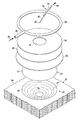
エリア22を外側32から再加工するために、不具合を含む構造20の一部は、相欠き(scarfing)と言われる再加工エリア22内で除去され得、これにより、構造20の厚さ「t」未満である深さ「d」を有するスカーフ空洞26が形成される。要するに、スカーフ空洞26は、構造20の厚さ「t」を部分的にのみ貫通する。図示された例では、スカーフ空洞26は、先細側面27、及び平底30を有しているが、他の適用では、側面27は、先細りしなくてもよく、底30は、平らでなくてもよい。
In order to rework the
再加工エリア38が外側32から所望の深さ「d」までスカーフ継ぎで接合されており、再加工パッチ24が製造され、スカーフ空洞26に配置される。再加工パッチ24は、内側33及び外側37を有する。再加工パッチ24は、例えば、編物又は織物を含み得る乾燥繊維強化材の層をまとめて積み重ね連結するなどによって製造される乾燥繊維プリフォームを含む。再加工パッチ24の形状は、スカーフ空洞26の形状に一致し得る。例えば、図示される適用において、再加工パッチ24の外縁は、スカーフ空洞26の先細側面27に一致するように先細りし得る。しかしながら、他の適用では、スカーフ空洞26及び再加工パッチ24は、階段状の特性を含むがこれに限定されない、他の断面特性を有し得る。さらに、乾燥繊維再加工パッチ24が図示されているが、樹脂で粘着力が高められた又は予備含浸された(プリプレグ)繊維強化パッチを使用して、開示される方法を実行することも可能であり得る。
A
可撓性のあり得る真空バッグ36は、再加工パッチ24上方に配置され、再加工パッチ24の外側32の構造20の表面38に密閉される。真空バッグ36は、樹脂注入前、注入中及び/又は注入後に再加工パッチ24を圧縮するために、真空バッグ36を排気する、適する真空発生装置45及びリザーバ44と連結される。再加工パッチ24の樹脂注入は、制御された圧力樹脂リザーバ46、着脱可能な真空源42及び制御された真空リザーバ44を備える樹脂注入システム35を使用して、実行され得る。樹脂注入システム35のいくつかの構成要素は、開示全体が本明細書中で参照することによって援用される、2008年2月26日に登録された米国特許番号7,334,782に図示された構成要素と類似であり得る。先述の米国特許では、樹脂リザーバ46が気圧未満の圧力まで排気され、真空補助される樹脂トランスファープロセスを制御するために真空バッグ36による循環的(反復)圧縮と組み合わせて使用され得る制御気圧樹脂注入システム(CAPRI)が開示される。しかしながら、他の種類の樹脂注入技術及び機器を使用して、開示された方法を実行することも可能であり得る。さらに、開示された方法は、オートクレーブ内で実行されてもよい。
A
真空源42は、スカーフ空洞26の底30付近で、修理パッチ24の内側に沿って、再加工パッチの最も厚い部分の下方に配置される。真空源42は、真空バッグ36を通過し得る真空ライン40により、真空リザーバ44と連結される。樹脂リザーバ46からの樹脂は、樹脂供給管48を通してパッチ24の外側37に供給される。真空源42は、スカーフ空洞26の底30で、パッチ24の内側33に沿った圧力を、真空発生装置45により生成されるパッチ24の外側37における真空バッグ36内の圧力よりも低い圧力レベルまで低下させる機能を果たす。パッチ24の内側33に沿った真空源42によってつくり出される圧力低下により、樹脂を再加工パッチ24の厚さ全体を通して流すパッチ24の内側33と外側37との間に圧力差が生じる。真空源42はまた、内側33付近で、もしそうしなければ、空隙を発生させる空気の封じ込めを生じ得る、再加工パッチ24の最も厚い部分の高圧エリアを排除する。パッチ24を通ってスカーフ空洞26の底30におけるパッチ24の内側33まで流れる余分な樹脂は、真空ライン40を通って真空リザーバ44内に逃げる。再加工パッチ24の樹脂注入に続き、真空源42は、樹脂が注入されたパッチ24から除去され、硬化前に密閉される。
A
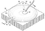
ここで、構造20のエリア26を再加工するための装置の一つの実用的な実施形態を示す図2、図3及び図4に注目する。この例では、構造20は、航空機産業で使用されるような複合積層外板20を含む。再加工エリア22は、外板20の厚さを部分的にのみ通ってスカーフ継ぎで接合されており(図2及び図4)、この結果、スカーフ空洞26は、先細側面27(図3を参照)及び一般的な平底30を有する。乾燥繊維プリフォームを備える再加工パッチ24が製造され、再加工パッチ24の内側33が構造20と接触した状態で、スカーフ空洞26内に配置される。再加工パッチ24は、スカーフ空洞26の先細側面27と実質的に一致する先細縁29(図4)を有し得る。リリースプライ66は、再加工パッチ24上方に配置される。リリースプライ66により、樹脂はリリースプライを通って流れることが可能であり、リリースプライ66は、限定されないが、多孔性のテフロン(登録商標)加工された繊維ガラスを含み得る。図に示される例示的実施形態では、スカーフ空洞26及び再加工パッチ24は各々、形状が実質的に円形である。しかしながら、開示される方法及び装置は、スカーフ空洞26及び再加工パッチ24が円形ではない、例えば、楕円形、正方形などであるエリア22を再加工するために使用され得ることに留意すべきである。
Attention is now directed to FIGS. 2, 3 and 4 which show one practical embodiment of an apparatus for reworking the
限定されないが、繊維ガラスなどの多孔性流動媒体62(図には、2つのプライが示されている)の一つ又は複数のプライは、リリースプライ66を覆い、再加工パッチ24のエリア上方に樹脂を分配する機能を果たす。流動媒体62は、再加工パッチ24への樹脂の流れの所望の波面生成を補助する「デッドゾーン」をつくり出す機能を果たす、中心の、概して円形又は他の形状の切欠き64を含み得る。いくつかの適用では、切欠き64は、パッチ24の形状によって必要とされない場合には、不要であり得る。円形の、螺旋状に巻かれた、樹脂分配管60は、ナイロン又は類似の材料で形成され得るが、流体媒体62の最上部に配置され、その外縁周囲で延在する。樹脂分配管60は、適用次第では、他の形状を有し得、樹脂供給管48と連結される。樹脂供給管48は、樹脂を制御圧力下で樹脂分配管60に供給する樹脂リザーバ46(図1)と連結される注入口54を含む。真空バッグ36は、樹脂分配管60だけではなく再加工パッチ24も覆い、シーラントテープを含み得る、適するシーラント70によって外板20の外側38に密閉される。
One or more plies of a porous fluid medium 62 (two plies are shown in the figure), such as but not limited to fiberglass, cover the
先ほど図1と関連付けて説明された真空源42は、真空針50などの真空デバイスを備え得る。中空針50の一端の先端25は、中空針50のもう一端が真空ライン40と連結される間は、開放される。中空針50は、真空バッグ36を貫通し47、流体媒体62の中心の切欠き64を通過して、修理パッチ24内に達するが、これにより中空針50の開口先端25は、スカーフ空洞26の底30で、実質的に再加工パッチ24の最も厚い部分の内側33に沿って位置決めされる。適するシーラント52は、真空バッグシーラント70に類似であり得るが、中空針50が真空バッグ36を貫通する47(図4)地点において、中空針50と真空バッグ36との間に実質的に真空気密のシールを形成する。
The
再加工パッチ24がスカーフ空洞26に配置され、樹脂分配管60及び流体媒体62が取り付けられた後の使用に際し、樹脂注入が開始され得、真空バッグ36は、圧縮圧力を再加工パッチ24に適用するために排気される。圧力下で樹脂リザーバ46から供給される樹脂は、樹脂供給管48を通って、樹脂分配管60内に流れ、更に流体媒体62上及び流体媒体62を通って流れる。流れている樹脂は、流れている樹脂を再加工パッチ24の上面上方に均一に分配するのを補助する流体媒体62を覆う。真空リザーバ44は、スカーフ空洞26の底30付近で、再加工パッチ24の最も厚い部分における圧力を低下させる中空針50の開口先端25をもたらす真空ライン40に真空を生成する。開口先端25における低圧エリアは、入ってくる樹脂の圧力を下回る。開口先端25におけるこの低下圧力により、再加工パッチ24の任意の空気又は他の揮発性物質が逃げる一方で、樹脂は、再加工パッチ24を通ってその最も厚い部分にまで至る。圧力勾配は、再加工パッチ24に樹脂が完全に注入され、空気が、樹脂注入プロセス中に再加工パッチ24内部に封じ込められないようにすることを保証する。余分な樹脂は、再加工パッチ24に存在する任意の空気/揮発性物質と共に、先端25に移動し、更に中空針50を通して真空ライン40に移動し、余分な樹脂/空気/揮発性物質が真空リザーバ44に搬送される。
In use after the
再加工パッチ24は、真空バッグ36を使用することによって、循環的に圧縮され得る。ここで、空気が乾燥繊維プリフォーム内に案内され、次に循環的な方法で封じ込められるため、プリフォームが更に圧縮される。樹脂リザーバ46の圧力は、再加工パッチ24に樹脂が注入されているときに、再加工パッチ24に加えられる正味の圧縮圧力(net compaction pressure)をより好ましく制御するために、真空バッグ36内部の圧力との関係で変更され得る。針50の開口先端25のサイズは、真空バッグ36に形成される貫通の直径を最小限にしつつ、針50を通した自由な樹脂の流れが、針50の壁における自然の摩擦力を十分に克服できるように選択され得る。再加工パッチ24にほぼ完全に樹脂が含浸されると、余分な樹脂は、中空針50を通って真空ライン40に流れ始め、真空リザーバ44に集められる。真空バッグ36内部の真空圧力の量は、針50への余分な樹脂の流れを誘導するために、調節され得る。真空リザーバ44内部の圧力はまた、中空針50を通した真空リザーバ44への余分な樹脂の流れを誘導するために調節され得る。再加工パッチ24の樹脂注入完了後、かつ硬化前に、針50は、再加工パッチ24から引き抜かれ得、針50による以前の貫通による真空バッグ36に残っている穴(図示されず)は、硬化中にバッグ36の真空の完全性を維持するために、真空バッグシーラントなどの適するシーラントを使用して密閉され得る。
The
適用次第では、複数の真空源42(図1)を大きな面積を有する再加工パッチ24のより厚い部分近傍に配置することが必要又は望ましいことがある。例えば、図5を参照すると、比較的大きな面積の再加工パッチ24には、間隔を空けた位置に複数の中空針50が提供される。シール52は、再加工パッチ24の全面積を覆う真空バッグ36に針50の各々を密閉する。一連の樹脂出口ライン40は、中空針50を、針50の位置で再加工パッチ24の内側圧力を低下させる真空リザーバ24と連結させる。樹脂は、樹脂供給管48により樹脂リザーバ46と連結される螺旋状に巻かれた樹脂分配管60を通して、再加工パッチ24内に流れる。
Depending on the application, it may be necessary or desirable to place a plurality of vacuum sources 42 (FIG. 1) near the thicker portion of the
図6は、パッチ24内部に配置され、パッチ24を通して樹脂を押し込むために使用される真空源42を使用した、構造20を再加工する方法のステップ全体を示す。ステップ67から開始し、パッチ24の内側33が構造20と接触した状態で、適するパッチ24が構造20上に配置される。ステップ69では、真空源42が、パッチ24の外側37からパッチ24に挿入される。次に、ステップ71では、真空源42が、パッチ24を通してパッチ24の内側33に樹脂を押し込むために使用される。所望であれば、公称厚さ0.005〜0.010インチの接着プライ、又は接着ライン39を強化する他の手段が、乾燥繊維パッチ24とスカーフ空洞26との間に配置され得る。
FIG. 6 shows the overall steps of the method of reworking the
ここで、樹脂が注入された再加工パッチ24を使用した構造20のエリアを再加工する別の方法のステップ全体を示す図7に注目する。ステップ72から開始し、パッチ24の内側33が構造20と接触するように、乾燥繊維再加工パッチ24が構造20上に配置される。所望であれば、公称厚さ0.005〜0.010インチの接着プライ、又は接着ライン39を強化する他の手段が、乾燥繊維パッチ24とスカーフ空洞26との間に配置され得る。ステップ74では、真空バッグ36が再加工パッチ24上方に配置され、構造20に密閉される。真空バッグ36は、樹脂の注入に先立って、所望のように乾燥繊維再加工パッチ24を圧縮するために排気され得る。ステップ76では、真空源42が、再加工パッチ24の内側33で位置決めされる。ステップ78では、樹脂が再加工パッチ24の外側37上に流され、ステップ80では、真空源42が、パッチ24の内側33での圧力を低下させつつ、樹脂を再加工パッチ24を通して再加工パッチ24の内側33に押し込むために使用される。ステップ82では、再加工パッチ24への樹脂の注入後に、真空源42が除去される。真空バッグ36は、ステップ78及び80中に再加工パッチ24に樹脂が注入されている間、再加工パッチ24での所望レベルの圧縮圧力を維持し得る。ステップ84では、樹脂が注入された再加工パッチ24は、真空バッグ36内部の圧力を低下させることにより、さらに圧縮され得る。ステップ86では、樹脂が注入されたパッチ24が硬化される。
Attention is now directed to FIG. 7 which shows the overall steps of another method of reworking the area of the
図8は、開示される実施形態による、複合外板20の再加工方法のステップを示す。ステップ88では、乾燥繊維プリフォーム再加工パッチ24が、乾燥織物又は乾燥編物の層をまとめて積み重ねることなどにより、準備される。ステップ90では、外板20が準備され、再加工されるエリア22で洗浄が行われ、必要であれば、不具合を除去し、再加工パッチ24が配置され得るスカーフ空洞26を形成するために、スカーフ継ぎで連結され得る。ステップ92では、再加工パッチ24が、スカーフ空洞26に取り付けられる。所望であれば、公称厚さ0.005〜0.010インチの接着プライ、又は接着ライン39を強化する他の手段が、乾燥繊維パッチ24とスカーフ空洞26との間に配置され得る。任意で、完成プライ(図示されず)が、ステップ94で、再加工パッチ24上方に適用され得る。ステップ96では、リリースプライ66などの分離媒体が取り付けられ、続いて、流体媒体62がステップ98で取り付けられる。ステップ100では、螺旋状に巻かれた樹脂分配管60を含み得る樹脂供給管が取り付けられ、樹脂リザーバ46と結合される。ステップ102では、真空バッグ36が、再加工パッチ24上方に取り付けられ、密閉される。ステップ104では、中空針50が、真空バッグ36、更には再加工パッチ24の最も厚い部分を通して挿入され、真空バッグ36に密閉される。中空針50の挿入中に、針50の開口先端25は、再加工パッチ24が再加工パッチ24の内側33において最大の厚さを有する場所で、スカーフ空洞の底において位置決めされる。
FIG. 8 illustrates the steps of a method for reworking the
ステップ106では、樹脂出口ライン40が、中空針50と真空リザーバ44との間で結合される。真空バッグ36は、ステップ108において、再加工パッチ24の圧縮を開始するために排気される。ステップ110では、樹脂を樹脂リザーバ46から樹脂分配管60を通って流体媒体62に流すことにより、樹脂の流れが開始する。ステップ112では、再加工パッチ24を通る樹脂の流れは、樹脂を再加工パッチ24に供給する樹脂リザーバ46と、再加工パッチ24の最も厚い部分での圧力を局所的に低下させ、余分な樹脂を取り除くために使用される真空リザーバ44との相対圧力を制御することにより制御される。ステップ114では、中空針50が、再加工パッチ24の最も厚い部分での圧力を低下させ、余分な樹脂を再加工パッチ24から真空リザーバ44に押し込むスカーフ空洞26の底30で真空を適用するために使用される。中空針50により適用される真空は、入ってくる樹脂に対する圧力より低く、したがって、樹脂をスカーフ空洞26の底に流れるようにする圧力差をつくり出す。ステップ116では、樹脂注入プロセスが完了し、続いてステップ118で、針50が再加工パッチ24から引き抜かれ、針50による以前の貫通に起因する真空バッグに残っている穴が密閉される。再加工パッチ24は、ステップ120で硬化され、ステップ122で、硬化された再加工パッチ24は、必要に応じて、トリミングされ、洗浄され、研磨され、滑らかにされる。
In
本開示の実施形態は、様々な潜在的用途、具体的には、例えば、航空宇宙、船舶、自動車における用途、及び自動レイアップ装備が使用され得る他の用途を含む輸送産業においての使用が見い出され得る。したがって、ここで図9及び図10を参照すると、本開示の実施形態は、図9に示す航空機の製造及び保守方法124、及び図10に示す航空機126に関して使用され得る。開示される実施形態の航空機の適用は、例えば、限定されないが、複合外板及び構造を担持する他の荷重を含み得る。製造前の段階では、例示的な方法124は、航空機126の仕様及び設計128と、材料の調達130とを含み得る。製造段階では、航空機126の、構成要素及びサブアセンブリの製造132と、システムインテグレーション134とが行われる。その後、航空機126は、認可及び納品136を経て、運航138に供される。顧客により運航される間に、航空機126は、改造、再構成、改修なども含み得る、定期的な整備及び保守140が予定される。運行中に、航空機126の構造的なエリアを再加工、修理又は補強するために、開示される方法が用いられ得る。
Embodiments of the present disclosure find use in the transportation industry, including a variety of potential applications, specifically aerospace, marine, automotive, and other applications where automatic layup equipment may be used. Can be. Accordingly, referring now to FIGS. 9 and 10, embodiments of the present disclosure may be used in connection with the aircraft manufacturing and
方法124の各プロセスは、システムインテグレーター、第三者、及び/又はオペレーター(例えば、顧客)によって実行又は実施され得る。本明細書の目的のために、システムインテグレーターは、限定しないが、任意の数の航空機製造者、及び主要システムの下請業者を含み得、第三者は、限定しないが、任意の数のベンダー、下請業者、及び供給業者を含み得、オペレーターは、航空会社、リース会社、軍事団体、サービス機関などであり得る。
Each process of
図10に示すように、例示的な方法124によって製造された航空機126は、複数のシステム144及び内装146を備えた機体142を含み得る。高レベルのシステム144の例は、推進システム148、電気システム150、油圧システム152、及び環境システム154のうちの一つ又は複数を含む。任意の数の他のシステムも含まれ得る。航空宇宙産業の例を示したが、本開示の原理は、海運及び自動車産業などの他の産業にも適用され得る。
As shown in FIG. 10, an
本明細書に具現化されたシステム及び方法は、製造及び保守方法124の一つ又は複数の任意の段階で採用され得る。例えば、製造プロセス128に対応する構成要素又はサブアセンブリは、航空機126の運航中に再加工され得る。また、一つ又は複数の装置の実施形態、方法の実施形態、若しくはそれらの組み合わせは、例えば、航空機126の組立を実質的に効率化するか、又は航空機12の整備コストを削減することにより、製造段階132及び134において利用され得る。同様に、装置の実施形態、方法の実施形態、若しくはそれらの組み合わせのうちの一又は複数は、航空機126の運航中に、例えば限定しないが、整備及び保守140に利用され得る。
The systems and methods embodied herein may be employed at any one or more stages of the manufacturing and
種々の例示的な実施形態の説明は、例示及び説明を目的として提示されており、網羅的な説明であること、又は開示された形態に実施形態を限定することを意図していない。当業者には、多くの修正例及び変形例が明らかだろう。更に、種々の例示的な実施形態は、他の例示的な実施形態と比較して、異なる利点を提供し得る。選択された一つ又は複数の実施形態は、実施形態の原理、実際の用途を最もよく説明するため、及び他の当業者に対し、様々な実施形態の開示内容と、考慮される特定の用途に適した様々な修正との理解を促すために選択及び記述されている。 The description of the various exemplary embodiments is presented for purposes of illustration and description, and is not intended to be exhaustive or limited to the embodiments disclosed. Many modifications and variations will be apparent to practitioners skilled in this art. Further, the various exemplary embodiments may provide different advantages compared to other exemplary embodiments. The selected embodiment (s) are intended to best illustrate the principles of the embodiments, practical applications, and to others skilled in the art, as well as the disclosure of the various embodiments and the particular applications considered. Selected and described to facilitate understanding with various modifications suitable for
Claims (10)
再加工する前記エリア(22)内で前記複合構造の一部を除去することと、
乾燥繊維パッチ(24)の内側(33)を前記一部が除去された後の複合構造(20)の凹部の底(30)に対して配置することと、
真空バッグ(36)を前記乾燥繊維パッチ(24)の外側(37)上方に配置することと、
真空源(42)を前記乾燥繊維パッチ(24)の前記外側(37)から前記乾燥繊維パッチ(24)に挿入することと、
樹脂を前記乾燥繊維パッチ(24)の前記外側(37)から前記乾燥繊維パッチ(24)に流し込むことにより、前記乾燥繊維パッチ(24)に樹脂を注入することと、
樹脂を前記乾燥繊維パッチ(24)を通して前記乾燥繊維パッチ(24)の前記内側(33)に押し込むために、前記真空源(42)を使用することと
を含み、
前記真空源(42)を挿入することは、中空針(50)を、前記真空バッグ(36)を通して、前記乾燥繊維パッチ(24)の内側(33)まで挿入することと、前記中空針(50)と前記真空バッグ(36)との間に実質的に真空気密のシール(52)を形成することとを更に含む、方法。 A method of reworking an area (22) of a composite structure (20),
Removing a portion of the composite structure within the area (22) to be reworked;
Placing the inside (33) of the dry fiber patch (24 ) against the bottom (30) of the recess of the composite structure (20) after the part has been removed ;
Placing a vacuum bag (36) above the outside (37) of the dry fiber patch (24);
Inserting a vacuum source (42) from the outside (37) of the dry fiber patch (24) into the dry fiber patch (24);
Pouring resin into the dry fiber patch (24) by pouring resin into the dry fiber patch (24) from the outside (37) of the dry fiber patch (24) ;
To force the resin into the inside (33) of the dry fiber patch (24) through said dry fiber patch (24), and a using the vacuum source (42),
Inserting said vacuum source (42), a hollow needle (50), through said vacuum bag (36), and inserting to the inside (33) of the dry fiber patch (24), said hollow needle (50 And forming a substantially vacuum tight seal (52) between the vacuum bag (36).
前記乾燥繊維パッチ(24)と前記複合構造(20)との間に接着強化層を配置することを含み、
前記真空源(42)を挿入することは、前記中空針(50)を、前記真空バッグ(36)及び前記乾燥繊維パッチ(24)の最も厚い部分を通って、実質的に前記底(30)まで挿入することをさらに含む、請求項1に記載の方法。 Placing the inside (33) of the dry fiber patch (24 ) against the bottom (30) of the recess of the composite structure (20) after the part has been removed ,
It looks including placing an adhesive reinforcing layer between the dry fibers patch (24) and said composite structure (20),
Inserting the vacuum source (42) causes the hollow needle (50) to pass through the vacuum bag (36) and the thickest part of the dry fiber patch (24), substantially through the bottom (30). The method of claim 1 , further comprising:
前記乾燥繊維パッチ(24)の内側(33)を前記一部が除去された後の複合構造(20)の凹部の底(30)に対して配置することは、前記スカーフ(26)の底(30)に対して前記乾燥繊維パッチ(24)の前記内側(33)を配置することを含み、前記真空源(42)を挿入することは、前記中空針(50)を前記乾燥繊維パッチ(24)の最も厚い部分を通って実質的に前記スカーフ(26)の底(30)まで挿入することを含む、請求項1から3の何れか一項に記載の方法。 Further comprising forming a scarf (26) partially through the thickness (t) of the composite structure (20);
Placing the inner side (33) of the dry fiber patch (24) against the bottom (30) of the recess of the composite structure (20) after the part has been removed is the bottom (30) of the scarf (26) 30) placing the inner side (33) of the dry fiber patch (24) relative to 30), and inserting the vacuum source (42) connects the hollow needle (50) to the dry fiber patch (24). 4) through the thickest part of the scarf (26) to the bottom (30) of the scarf (26).
前記中空針(50)を前記乾燥繊維パッチ(24)から及び前記真空バッグ(36)から引き抜くことと、
前記真空バッグ(36)を通した前記中空針(50)の挿入中に前記真空バッグ(36)を貫通したことにより生じる前記真空バッグ(36)の穴を密閉することと
を含む、請求項3に記載の方法。 Removing the vacuum source (42) from the dry fiber patch (24) comprises:
Withdrawing the hollow needle (50) from the dry fiber patch (24) and from the vacuum bag (36);
And a possible sealing the bore of the hollow needle through the vacuum bag (36) (50) said vacuum bag (36) caused by said through the vacuum bag (36) during insertion of claim 3 The method described in 1.
複数の前記中空針(50)を前記乾燥繊維パッチ(24)を通して、前記乾燥繊維パッチ(24)のエリア上方で間隔を空けた位置に挿入することを含む、請求項1から5の何れか一項に記載の方法。 Inserting the vacuum source (42) into the dry fiber patch (24),
Inserting a plurality of said hollow needles (50) through said dry fiber patch (24) at spaced locations above the area of said dry fiber patch (24). The method according to item.
樹脂分配管(60)を、前記真空バッグ(36)下方の前記乾燥繊維パッチ(24)の前記外側(37)に配置することと、
樹脂を前記樹脂分配管(60)に供給することと
を含む、請求項1から7の何れか一項に記載の方法。 Pouring the resin from the outside (37) of the dry fiber patch (24) into the dry fiber patch (24),
Placing a resin distribution pipe (60) on the outside (37) of the dry fiber patch (24) below the vacuum bag (36);
Feeding a resin to the resin distribution pipe (60).
前記内側(33)が、前記一部が除去された後の複合構造(20)の凹部の底(30)に対して配置される前記乾燥繊維パッチ(24)を圧縮するための、前記乾燥繊維パッチ(24)の前記外側(37)上方に配置されるように適合される真空バッグ(36)と、
前記真空バッグ(36)を貫通し、前記乾燥繊維パッチ(24)の厚さ(d)を通して、前記乾燥繊維パッチ(24)の内側(33)まで、下に延びるように適合される中空針(50)と、
前記中空針(50)と前記真空バッグ(36)との間の真空シール(52)と、
前記乾燥繊維パッチ(24)の前記内側(33)で真空を生成するための、前記中空針(50)と連結される真空ライン(40)と
を備える、装置。 An apparatus for reworking an area (22) of a composite structure (20) using resin injection of a dry fiber patch (24) having an inner side (33) and an outer side (37), said reworking A portion of the composite structure is removed within the area (22);
The dry fiber for compressing the dry fiber patch (24), wherein the inner side (33) is placed against the bottom (30) of the recess of the composite structure (20) after the part has been removed A vacuum bag (36) adapted to be placed over said outer side (37) of patch (24);
A hollow needle adapted to extend through the vacuum bag (36) and down through the thickness (d) of the dry fiber patch (24) to the inside (33) of the dry fiber patch (24) ( 50),
A vacuum seal (52) between the hollow needle (50) and the vacuum bag (36);
The dry fibers patches for generating a vacuum the inside (33) of (24), and a vacuum line (40) connected to the hollow needle (50), device.
前記乾燥繊維パッチ(24)の前記内側(33)で真空を生成し、余分な樹脂を前記乾燥繊維パッチ(24)から取り除くための、前記中空針(50)と連結された真空源(42)と
を更に備え、
前記中空針(50)は、前記乾燥繊維パッチ(24)の最も厚い部分を通って、実質的に前記底(30)まで、下に延びるようにさらに適合される、請求項9に記載の装置。 A resin reservoir (46) for supplying resin to the outside (37) of the dry fiber patch (24) at a controlled partial pressure;
A vacuum source (42) connected to the hollow needle (50) for creating a vacuum on the inside (33) of the dry fiber patch (24) and removing excess resin from the dry fiber patch (24) In addition example Bei the door,
The apparatus of claim 9, wherein the hollow needle (50) is further adapted to extend down through the thickest portion of the dry fiber patch (24) to substantially the bottom (30). .
Applications Claiming Priority (3)
| Application Number | Priority Date | Filing Date | Title |
|---|---|---|---|
| US13/761,785 US9579873B2 (en) | 2013-02-07 | 2013-02-07 | Method and apparatus for reworking structures |
| US13/761,785 | 2013-02-07 | ||
| PCT/US2014/010290 WO2014123646A1 (en) | 2013-02-07 | 2014-01-06 | Method and apparatus for reworking structures |
Publications (3)
| Publication Number | Publication Date |
|---|---|
| JP2016506885A JP2016506885A (en) | 2016-03-07 |
| JP2016506885A5 JP2016506885A5 (en) | 2017-01-26 |
| JP6452628B2 true JP6452628B2 (en) | 2019-01-16 |
Family
ID=50031549
Family Applications (1)
| Application Number | Title | Priority Date | Filing Date |
|---|---|---|---|
| JP2015556943A Active JP6452628B2 (en) | 2013-02-07 | 2014-01-06 | Method and apparatus for reworking structures |
Country Status (11)
| Country | Link |
|---|---|
| US (1) | US9579873B2 (en) |
| EP (1) | EP2953786B1 (en) |
| JP (1) | JP6452628B2 (en) |
| KR (1) | KR101988470B1 (en) |
| CN (1) | CN104918774B (en) |
| BR (1) | BR112015017742B1 (en) |
| CA (1) | CA2898023C (en) |
| ES (1) | ES2678097T3 (en) |
| PT (1) | PT2953786T (en) |
| TR (1) | TR201807804T4 (en) |
| WO (1) | WO2014123646A1 (en) |
Families Citing this family (12)
| Publication number | Priority date | Publication date | Assignee | Title |
|---|---|---|---|---|
| GB2531600A (en) | 2014-10-24 | 2016-04-27 | Short Brothers Plc | Apparatus and methods for manufacturing and repairing fibre-reinforced composite materials |
| FR3048634B1 (en) * | 2016-03-11 | 2018-04-06 | Safran Aircraft Engines | DEVICE AND METHOD FOR INJECTION MOLDING A LIQUID POLYMER |
| CN109070500B (en) * | 2016-03-25 | 2021-04-20 | 肖特兄弟公司 | Apparatus and method for making composite laminates |
| US10946594B1 (en) * | 2017-01-06 | 2021-03-16 | Cornerstone Research Group, Inc. | Reinforced polymer-infused fiber composite repair system and methods for repairing composite materials |
| ES2773182T3 (en) | 2017-09-04 | 2020-07-09 | Grupo Navec Servicios Ind Sl | On-site reconstruction method to rebuild and repair on-site pipelines and containment structures |
| US10814533B2 (en) * | 2017-11-30 | 2020-10-27 | The Boeing Company | Systems and methods for applying vacuum pressure to composite parts |
| US11110668B2 (en) * | 2018-06-26 | 2021-09-07 | The Boeing Company | Apparatus and method for facilitating a vacuum bagging operation during fabrication of a composite laminate |
| US11548102B2 (en) * | 2020-07-31 | 2023-01-10 | General Electric Company | Method for repairing composite components using a plug |
| US20220184900A1 (en) * | 2020-12-11 | 2022-06-16 | Remarkable Foods, Inc. | Method and Apparatus For Forming a Composite Object |
| EP4019231B1 (en) * | 2020-12-17 | 2024-01-03 | The Boeing Company | Systems and methods for adhesive-injected patch repair |
| US11865656B2 (en) * | 2021-06-17 | 2024-01-09 | The Boeing Company | In situ crack repair in structures |
| CN113877865B (en) * | 2021-11-10 | 2022-12-09 | 段瑞 | Inside purger of green house membrane |
Family Cites Families (19)
| Publication number | Priority date | Publication date | Assignee | Title |
|---|---|---|---|---|
| FR89458E (en) | 1965-05-31 | 1967-06-30 | Construction process in light materials, bodies of all kinds, such as roofs or walls of buildings, tanks or even boat hulls | |
| JPS5862017A (en) * | 1981-10-09 | 1983-04-13 | Hitachi Zosen Corp | Method of molding fiber-reinforced resin item |
| US5699838A (en) | 1995-05-22 | 1997-12-23 | Inliner, U.S.A. | Apparatus for vacuum impregnation of a flexible, hollow tube |
| US6555045B2 (en) * | 1999-01-11 | 2003-04-29 | Northrop Grumman Corporation | Grooved mold apparatus and process for forming fiber reinforced composite structures |
| DE60018455T3 (en) | 1999-12-07 | 2009-02-19 | The Boeing Company, Seattle | DOUBLE FILMS VACUUM INJECTION METHOD FOR THE PRODUCTION OF A COMPOSITE MATERIAL AND COMPOSITE MATERIAL PRODUCED THEREWITH |
| US6385836B1 (en) * | 2000-06-30 | 2002-05-14 | Lockheed Martin Corporation | Method for composite material repair |
| US6586054B2 (en) | 2001-04-24 | 2003-07-01 | The United States Of America As Represented By The Secretary Of The Army | Apparatus and method for selectively distributing and controlling a means for impregnation of fibrous articles |
| US20030019567A1 (en) | 2001-07-26 | 2003-01-30 | Burpo Steven J. | Vacuum assisted resin transfer method for co-bonding composite laminate structures |
| US7138028B2 (en) | 2001-07-26 | 2006-11-21 | The Boeing Company | Vacuum assisted resin transfer method for co-bonding composite laminate structures |
| CA2484174C (en) | 2002-05-29 | 2008-12-02 | The Boeing Company | Controlled atmospheric pressure resin infusion process |
| JP4220874B2 (en) * | 2002-12-11 | 2009-02-04 | 三菱重工業株式会社 | Resin impregnation sensor / repair device, resin impregnation repair device and repair method |
| US6896841B2 (en) | 2003-03-20 | 2005-05-24 | The Boeing Company | Molding process and apparatus for producing unified composite structures |
| DK176135B1 (en) * | 2004-11-30 | 2006-09-18 | Lm Glasfiber As | Vacuum infusion using semipermeable membrane |
| US7633040B2 (en) | 2005-11-14 | 2009-12-15 | The Boeing Company | Bulk resin infusion system apparatus and method |
| US20080136060A1 (en) * | 2006-12-08 | 2008-06-12 | Gkn Westland Aerospace, Inc. | System and method for forming and curing a composite structure |
| WO2009080038A1 (en) * | 2007-12-21 | 2009-07-02 | Vestas Wind Systems A/S | A method of repairing a fibre composite solid member |
| US20090309260A1 (en) | 2008-06-12 | 2009-12-17 | Kenneth Herbert Keuchel | Method of delivering a thermoplastic and/or crosslinking resin to a composite laminate structure |
| WO2012154544A2 (en) | 2011-05-06 | 2012-11-15 | Purdue Research Foundation | Method and system of vacuum assisted resin transfer molding for repair of composite materials and structure |
| US8945321B2 (en) | 2011-05-30 | 2015-02-03 | The Boeing Company | Method and apparatus for reworking structures using resin infusion of fiber preforms |
-
2013
- 2013-02-07 US US13/761,785 patent/US9579873B2/en active Active
-
2014
- 2014-01-06 EP EP14702330.3A patent/EP2953786B1/en active Active
- 2014-01-06 TR TR2018/07804T patent/TR201807804T4/en unknown
- 2014-01-06 CN CN201480004886.5A patent/CN104918774B/en active Active
- 2014-01-06 ES ES14702330.3T patent/ES2678097T3/en active Active
- 2014-01-06 WO PCT/US2014/010290 patent/WO2014123646A1/en active Application Filing
- 2014-01-06 PT PT147023303T patent/PT2953786T/en unknown
- 2014-01-06 CA CA2898023A patent/CA2898023C/en active Active
- 2014-01-06 BR BR112015017742-5A patent/BR112015017742B1/en active IP Right Grant
- 2014-01-06 JP JP2015556943A patent/JP6452628B2/en active Active
- 2014-01-06 KR KR1020157021566A patent/KR101988470B1/en active IP Right Grant
Also Published As
| Publication number | Publication date |
|---|---|
| US20140216634A1 (en) | 2014-08-07 |
| WO2014123646A1 (en) | 2014-08-14 |
| EP2953786A1 (en) | 2015-12-16 |
| BR112015017742B1 (en) | 2020-11-10 |
| PT2953786T (en) | 2018-07-04 |
| EP2953786B1 (en) | 2018-04-18 |
| CN104918774A (en) | 2015-09-16 |
| JP2016506885A (en) | 2016-03-07 |
| CN104918774B (en) | 2017-04-05 |
| ES2678097T3 (en) | 2018-08-08 |
| KR20150115795A (en) | 2015-10-14 |
| KR101988470B1 (en) | 2019-06-12 |
| BR112015017742A2 (en) | 2017-07-11 |
| TR201807804T4 (en) | 2018-06-21 |
| CA2898023A1 (en) | 2014-08-14 |
| US9579873B2 (en) | 2017-02-28 |
| CA2898023C (en) | 2018-10-16 |
Similar Documents
| Publication | Publication Date | Title |
|---|---|---|
| JP6452628B2 (en) | Method and apparatus for reworking structures | |
| JP5988692B2 (en) | Method and apparatus for reworking structures using resin injection of fiber preforms | |
| US9701073B2 (en) | Method for repairing a member comprising a fiber-reinforced plastic | |
| JP6490340B2 (en) | Method and system for making composite structures having void fillers comprising short fiber materials | |
| JP5801885B2 (en) | Composite structure having integral stiffener and method for producing the same | |
| US20110221093A1 (en) | Method and system for manufacturing wind turbine blades | |
| AU2018204632A1 (en) | Fabrication of composite laminates using temporarily stitched preforms | |
| JP2013527894A (en) | Integrated engine nacelle structure | |
| EP2599615B1 (en) | Reducing porosity in composite structures | |
| US20130327477A1 (en) | Non-Vented Bladder System for Curing Composite Parts | |
| US7374715B2 (en) | Co-cured resin transfer molding manufacturing method | |
| JP2021054398A (en) | Method and tool for manufacturing composite material window frame of aircraft | |
| JP7282890B2 (en) | Method for manufacturing fiber reinforced polymer composite beams, in particular girder beams for wind turbine rotor blades |
Legal Events
| Date | Code | Title | Description |
|---|---|---|---|
| A521 | Request for written amendment filed |
Free format text: JAPANESE INTERMEDIATE CODE: A523 Effective date: 20161208 |
|
| A621 | Written request for application examination |
Free format text: JAPANESE INTERMEDIATE CODE: A621 Effective date: 20161208 |
|
| A977 | Report on retrieval |
Free format text: JAPANESE INTERMEDIATE CODE: A971007 Effective date: 20171206 |
|
| A131 | Notification of reasons for refusal |
Free format text: JAPANESE INTERMEDIATE CODE: A131 Effective date: 20180123 |
|
| A601 | Written request for extension of time |
Free format text: JAPANESE INTERMEDIATE CODE: A601 Effective date: 20180420 |
|
| A521 | Request for written amendment filed |
Free format text: JAPANESE INTERMEDIATE CODE: A523 Effective date: 20180621 |
|
| TRDD | Decision of grant or rejection written | ||
| A01 | Written decision to grant a patent or to grant a registration (utility model) |
Free format text: JAPANESE INTERMEDIATE CODE: A01 Effective date: 20181113 |
|
| A61 | First payment of annual fees (during grant procedure) |
Free format text: JAPANESE INTERMEDIATE CODE: A61 Effective date: 20181211 |
|
| R150 | Certificate of patent or registration of utility model |
Ref document number: 6452628 Country of ref document: JP Free format text: JAPANESE INTERMEDIATE CODE: R150 |
|
| R250 | Receipt of annual fees |
Free format text: JAPANESE INTERMEDIATE CODE: R250 |
|
| R250 | Receipt of annual fees |
Free format text: JAPANESE INTERMEDIATE CODE: R250 |
|
| R250 | Receipt of annual fees |
Free format text: JAPANESE INTERMEDIATE CODE: R250 |