JP6451674B2 - Driving assistance device - Google Patents
Driving assistance device Download PDFInfo
- Publication number
- JP6451674B2 JP6451674B2 JP2016049616A JP2016049616A JP6451674B2 JP 6451674 B2 JP6451674 B2 JP 6451674B2 JP 2016049616 A JP2016049616 A JP 2016049616A JP 2016049616 A JP2016049616 A JP 2016049616A JP 6451674 B2 JP6451674 B2 JP 6451674B2
- Authority
- JP
- Japan
- Prior art keywords
- driving
- unit
- driving support
- vehicle
- driver
- Prior art date
- Legal status (The legal status is an assumption and is not a legal conclusion. Google has not performed a legal analysis and makes no representation as to the accuracy of the status listed.)
- Active
Links
- 238000001514 detection method Methods 0.000 claims description 28
- 230000009467 reduction Effects 0.000 claims description 9
- 230000007850 degeneration Effects 0.000 claims description 5
- 230000003247 decreasing effect Effects 0.000 claims description 4
- 238000000034 method Methods 0.000 description 47
- 230000008569 process Effects 0.000 description 43
- 230000001133 acceleration Effects 0.000 description 7
- 230000000694 effects Effects 0.000 description 7
- 230000006870 function Effects 0.000 description 6
- 230000005856 abnormality Effects 0.000 description 3
- 101000969594 Homo sapiens Modulator of apoptosis 1 Proteins 0.000 description 2
- 102100021440 Modulator of apoptosis 1 Human genes 0.000 description 2
- 238000010586 diagram Methods 0.000 description 2
- 238000012886 linear function Methods 0.000 description 2
- 230000004044 response Effects 0.000 description 2
- 239000004065 semiconductor Substances 0.000 description 2
- 125000002066 L-histidyl group Chemical group [H]N1C([H])=NC(C([H])([H])[C@](C(=O)[*])([H])N([H])[H])=C1[H] 0.000 description 1
- 230000002159 abnormal effect Effects 0.000 description 1
- 230000008859 change Effects 0.000 description 1
- 239000000470 constituent Substances 0.000 description 1
- 238000003745 diagnosis Methods 0.000 description 1
- 238000005516 engineering process Methods 0.000 description 1
- 230000001151 other effect Effects 0.000 description 1
- 230000001629 suppression Effects 0.000 description 1
Images


Classifications
-
- B—PERFORMING OPERATIONS; TRANSPORTING
- B60—VEHICLES IN GENERAL
- B60W—CONJOINT CONTROL OF VEHICLE SUB-UNITS OF DIFFERENT TYPE OR DIFFERENT FUNCTION; CONTROL SYSTEMS SPECIALLY ADAPTED FOR HYBRID VEHICLES; ROAD VEHICLE DRIVE CONTROL SYSTEMS FOR PURPOSES NOT RELATED TO THE CONTROL OF A PARTICULAR SUB-UNIT
- B60W50/00—Details of control systems for road vehicle drive control not related to the control of a particular sub-unit, e.g. process diagnostic or vehicle driver interfaces
- B60W50/02—Ensuring safety in case of control system failures, e.g. by diagnosing, circumventing or fixing failures
- B60W50/0205—Diagnosing or detecting failures; Failure detection models
-
- B—PERFORMING OPERATIONS; TRANSPORTING
- B60—VEHICLES IN GENERAL
- B60W—CONJOINT CONTROL OF VEHICLE SUB-UNITS OF DIFFERENT TYPE OR DIFFERENT FUNCTION; CONTROL SYSTEMS SPECIALLY ADAPTED FOR HYBRID VEHICLES; ROAD VEHICLE DRIVE CONTROL SYSTEMS FOR PURPOSES NOT RELATED TO THE CONTROL OF A PARTICULAR SUB-UNIT
- B60W30/00—Purposes of road vehicle drive control systems not related to the control of a particular sub-unit, e.g. of systems using conjoint control of vehicle sub-units, or advanced driver assistance systems for ensuring comfort, stability and safety or drive control systems for propelling or retarding the vehicle
- B60W30/08—Active safety systems predicting or avoiding probable or impending collision or attempting to minimise its consequences
- B60W30/09—Taking automatic action to avoid collision, e.g. braking and steering
-
- B—PERFORMING OPERATIONS; TRANSPORTING
- B60—VEHICLES IN GENERAL
- B60W—CONJOINT CONTROL OF VEHICLE SUB-UNITS OF DIFFERENT TYPE OR DIFFERENT FUNCTION; CONTROL SYSTEMS SPECIALLY ADAPTED FOR HYBRID VEHICLES; ROAD VEHICLE DRIVE CONTROL SYSTEMS FOR PURPOSES NOT RELATED TO THE CONTROL OF A PARTICULAR SUB-UNIT
- B60W30/00—Purposes of road vehicle drive control systems not related to the control of a particular sub-unit, e.g. of systems using conjoint control of vehicle sub-units, or advanced driver assistance systems for ensuring comfort, stability and safety or drive control systems for propelling or retarding the vehicle
- B60W30/10—Path keeping
- B60W30/12—Lane keeping
-
- B—PERFORMING OPERATIONS; TRANSPORTING
- B60—VEHICLES IN GENERAL
- B60W—CONJOINT CONTROL OF VEHICLE SUB-UNITS OF DIFFERENT TYPE OR DIFFERENT FUNCTION; CONTROL SYSTEMS SPECIALLY ADAPTED FOR HYBRID VEHICLES; ROAD VEHICLE DRIVE CONTROL SYSTEMS FOR PURPOSES NOT RELATED TO THE CONTROL OF A PARTICULAR SUB-UNIT
- B60W50/00—Details of control systems for road vehicle drive control not related to the control of a particular sub-unit, e.g. process diagnostic or vehicle driver interfaces
- B60W50/02—Ensuring safety in case of control system failures, e.g. by diagnosing, circumventing or fixing failures
- B60W50/0225—Failure correction strategy
-
- B—PERFORMING OPERATIONS; TRANSPORTING
- B60—VEHICLES IN GENERAL
- B60W—CONJOINT CONTROL OF VEHICLE SUB-UNITS OF DIFFERENT TYPE OR DIFFERENT FUNCTION; CONTROL SYSTEMS SPECIALLY ADAPTED FOR HYBRID VEHICLES; ROAD VEHICLE DRIVE CONTROL SYSTEMS FOR PURPOSES NOT RELATED TO THE CONTROL OF A PARTICULAR SUB-UNIT
- B60W50/00—Details of control systems for road vehicle drive control not related to the control of a particular sub-unit, e.g. process diagnostic or vehicle driver interfaces
- B60W50/08—Interaction between the driver and the control system
- B60W50/10—Interpretation of driver requests or demands
-
- B—PERFORMING OPERATIONS; TRANSPORTING
- B60—VEHICLES IN GENERAL
- B60W—CONJOINT CONTROL OF VEHICLE SUB-UNITS OF DIFFERENT TYPE OR DIFFERENT FUNCTION; CONTROL SYSTEMS SPECIALLY ADAPTED FOR HYBRID VEHICLES; ROAD VEHICLE DRIVE CONTROL SYSTEMS FOR PURPOSES NOT RELATED TO THE CONTROL OF A PARTICULAR SUB-UNIT
- B60W50/00—Details of control systems for road vehicle drive control not related to the control of a particular sub-unit, e.g. process diagnostic or vehicle driver interfaces
- B60W50/08—Interaction between the driver and the control system
- B60W50/14—Means for informing the driver, warning the driver or prompting a driver intervention
-
- B—PERFORMING OPERATIONS; TRANSPORTING
- B60—VEHICLES IN GENERAL
- B60W—CONJOINT CONTROL OF VEHICLE SUB-UNITS OF DIFFERENT TYPE OR DIFFERENT FUNCTION; CONTROL SYSTEMS SPECIALLY ADAPTED FOR HYBRID VEHICLES; ROAD VEHICLE DRIVE CONTROL SYSTEMS FOR PURPOSES NOT RELATED TO THE CONTROL OF A PARTICULAR SUB-UNIT
- B60W60/00—Drive control systems specially adapted for autonomous road vehicles
- B60W60/005—Handover processes
- B60W60/0053—Handover processes from vehicle to occupant
-
- B—PERFORMING OPERATIONS; TRANSPORTING
- B62—LAND VEHICLES FOR TRAVELLING OTHERWISE THAN ON RAILS
- B62D—MOTOR VEHICLES; TRAILERS
- B62D1/00—Steering controls, i.e. means for initiating a change of direction of the vehicle
- B62D1/24—Steering controls, i.e. means for initiating a change of direction of the vehicle not vehicle-mounted
- B62D1/28—Steering controls, i.e. means for initiating a change of direction of the vehicle not vehicle-mounted non-mechanical, e.g. following a line or other known markers
- B62D1/286—Systems for interrupting non-mechanical steering due to driver intervention
-
- B—PERFORMING OPERATIONS; TRANSPORTING
- B62—LAND VEHICLES FOR TRAVELLING OTHERWISE THAN ON RAILS
- B62D—MOTOR VEHICLES; TRAILERS
- B62D15/00—Steering not otherwise provided for
- B62D15/02—Steering position indicators ; Steering position determination; Steering aids
- B62D15/025—Active steering aids, e.g. helping the driver by actively influencing the steering system after environment evaluation
-
- B—PERFORMING OPERATIONS; TRANSPORTING
- B62—LAND VEHICLES FOR TRAVELLING OTHERWISE THAN ON RAILS
- B62D—MOTOR VEHICLES; TRAILERS
- B62D6/00—Arrangements for automatically controlling steering depending on driving conditions sensed and responded to, e.g. control circuits
-
- B—PERFORMING OPERATIONS; TRANSPORTING
- B60—VEHICLES IN GENERAL
- B60W—CONJOINT CONTROL OF VEHICLE SUB-UNITS OF DIFFERENT TYPE OR DIFFERENT FUNCTION; CONTROL SYSTEMS SPECIALLY ADAPTED FOR HYBRID VEHICLES; ROAD VEHICLE DRIVE CONTROL SYSTEMS FOR PURPOSES NOT RELATED TO THE CONTROL OF A PARTICULAR SUB-UNIT
- B60W2420/00—Indexing codes relating to the type of sensors based on the principle of their operation
- B60W2420/40—Photo or light sensitive means, e.g. infrared sensors
- B60W2420/403—Image sensing, e.g. optical camera
-
- B60W2420/408—
-
- B—PERFORMING OPERATIONS; TRANSPORTING
- B60—VEHICLES IN GENERAL
- B60W—CONJOINT CONTROL OF VEHICLE SUB-UNITS OF DIFFERENT TYPE OR DIFFERENT FUNCTION; CONTROL SYSTEMS SPECIALLY ADAPTED FOR HYBRID VEHICLES; ROAD VEHICLE DRIVE CONTROL SYSTEMS FOR PURPOSES NOT RELATED TO THE CONTROL OF A PARTICULAR SUB-UNIT
- B60W2510/00—Input parameters relating to a particular sub-units
- B60W2510/20—Steering systems
-
- B—PERFORMING OPERATIONS; TRANSPORTING
- B60—VEHICLES IN GENERAL
- B60W—CONJOINT CONTROL OF VEHICLE SUB-UNITS OF DIFFERENT TYPE OR DIFFERENT FUNCTION; CONTROL SYSTEMS SPECIALLY ADAPTED FOR HYBRID VEHICLES; ROAD VEHICLE DRIVE CONTROL SYSTEMS FOR PURPOSES NOT RELATED TO THE CONTROL OF A PARTICULAR SUB-UNIT
- B60W2540/00—Input parameters relating to occupants
- B60W2540/18—Steering angle
Description
本発明は、ドライバによる車両の運転操作を支援する技術に関する。なお、本明細書において、車両に搭載又は装着された機器のうち、例えば操舵輪,スロットルバルブ,ホイールシリンダ等、車両の走行に係る機器であって、かつ、運転操作の結果として動作される機器を車載器と呼ぶ。 The present invention relates to a technique for supporting a driving operation of a vehicle by a driver. In the present specification, among the devices mounted on or mounted on the vehicle, for example, devices related to traveling of the vehicle, such as steering wheels, throttle valves, and wheel cylinders, and devices that are operated as a result of the driving operation. Is called on-vehicle equipment.
従来、車両の走行に係る車載器(例えば操舵輪)を自動的に駆動して、ドライバによる車両の運転操作を支援する運転支援装置が知られている。また、この種の運転支援装置では、前記車載器を動作させて運転操作を行うためにドライバによって操作される操作部が、閾値を超える操作力又は操作量で操作されたとき、運転支援を中止して手動運転に切り換えることが考えられている。例えば特許文献1には、走行レーンを維持するようにステアリングホイールをモータで駆動する運転支援中に、ステアリングホイールに閾値以上のトルクがドライバによって加えられると、前記運転支援を中止して手動運転に切り換える装置が開示されている。また、特許文献1に記載の装置では、ステアリングホイールをドライバが軽く握っているかしっかり握っているかなどに応じて、前記閾値を変えている。
2. Description of the Related Art Conventionally, there is known a driving support device that automatically drives an in-vehicle device (for example, a steered wheel) related to traveling of a vehicle to assist a driving operation of the vehicle by a driver. Further, in this type of driving support device, driving support is stopped when the operating unit operated by the driver to operate the vehicle-mounted device and perform a driving operation is operated with an operating force or operating amount exceeding a threshold value. Therefore, switching to manual operation is considered. For example, in
しかしながら、特許文献1に記載の装置では、運転支援装置側の異常等によって運転支援を中止せざるを得ない場合にも、車線変更等のためにドライバが自らの所望に応じて運転支援を中止させる場合にも、同様の制御がなされる。運転支援装置に異常等が発生して、運転支援の信頼性が低下した場合には、運転支援を中止して手動運転に切り換える必要があるが、そのような切り換えは安全かつ円滑になされる必要がある。
However, in the device described in
本発明は、こうした問題にかんがみてなされたものであり、ドライバによる車両の運転操作を支援する運転支援装置において、運転支援の信頼性が低下した場合に、運転支援を中止させて手動運転に切り換える処理を円滑に行うことを目的としている。 The present invention has been made in view of these problems, and in a driving support device that supports driving operation of a vehicle by a driver, when the reliability of driving support is reduced, the driving support is stopped and switched to manual driving. The purpose is to facilitate the processing.
本発明の運転支援装置は、操作部(3)と、運転支援部(12)と、操作検出部(25)と、切換制御部(13)と、信頼検出部(15)と、閾値低減部(14)と、を備える。操作部は、車両の走行に係る車載器(30)を動作させて運転操作を行うために、ドライバによって操作される。運転支援部は、前記操作部が操作されていない状況下で、前記車載器を自動的に駆動する運転支援を実行する。操作検出部は、前記操作部がドライバによって操作される操作力又は操作量を検出する。切換制御部は、ドライバによる前記操作部に対する操作に応じて前記車載器が動作する運転状態を手動運転として、前記運転支援部が前記運転支援を実行している運転支援時に、前記操作検出部によって検出される操作力又は操作量が閾値を超えたとき、前記運転支援部による運転支援を中止させ、前記運転支援がなされる運転状態から前記手動運転に切り換える。信頼検出部は、前記運転支援部による運転支援の信頼度が低下したことを検出する。閾値低減部は、前記運転支援時に、前記信頼検出部が前記信頼度の低下を検出したとき、前記閾値を低減させる。 The driving support device of the present invention includes an operation unit (3), a driving support unit (12), an operation detection unit (25), a switching control unit (13), a reliability detection unit (15), and a threshold reduction unit. (14). The operation unit is operated by a driver in order to perform a driving operation by operating the vehicle-mounted device (30) related to traveling of the vehicle. The driving support unit executes driving support for automatically driving the vehicle-mounted device under a situation where the operation unit is not operated. The operation detection unit detects an operation force or an operation amount at which the operation unit is operated by a driver. The switching control unit sets the driving state in which the vehicle-mounted device operates in response to an operation by the driver to the operation unit as manual driving, and the driving detection unit performs driving support by the operation detection unit during driving support. When the detected operation force or operation amount exceeds a threshold value, the driving support by the driving support unit is stopped, and the driving state in which the driving support is performed is switched to the manual driving. A reliability detection part detects that the reliability of the driving assistance by the said driving assistance part fell. The threshold reduction unit reduces the threshold when the reliability detection unit detects a decrease in the reliability during the driving support.
このような構成によれば、運転支援部による運転支援時に、その運転支援の信頼性が低下したことを信頼検出部が検出した場合、閾値低減部が閾値を低減させる。すると、ドライバが操作部をそれほど大きな操作力又は操作量で操作しなくても、当該操作力又は操作量が閾値を超え、前記運転支援を中止させて手動運転に切り換える処理が切換制御部によって実行される。このため、運転支援の信頼性が低下した場合に、運転支援を中止させて手動運転に切り換える処理を円滑に行うことができる。 According to such a configuration, when the reliability detection unit detects that the reliability of the driving support has decreased during driving support by the driving support unit, the threshold reduction unit reduces the threshold. Then, even if the driver does not operate the operation unit with a very large operation force or operation amount, the operation force or operation amount exceeds the threshold value, and the process for stopping the driving support and switching to the manual operation is executed by the switching control unit. Is done. For this reason, when the reliability of driving assistance falls, the process which stops driving assistance and switches to manual driving can be performed smoothly.
なお、この欄及び特許請求の範囲に記載した括弧内の符号は、一つの態様として後述する実施形態に記載の具体的手段との対応関係を示すものであって、本発明の技術的範囲を限定するものではない。 In addition, the code | symbol in the parenthesis described in this column and a claim shows the correspondence with the specific means as described in embodiment mentioned later as one aspect, Comprising: The technical scope of this invention is shown. It is not limited.
以下、本発明が適用された実施形態について、図面を用いて説明する。
[1.第1実施形態]
[1−1.構成]
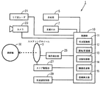
図1に示す運転支援装置1は、車両に搭載される装置であって、ステアリングホイール3と、告知部5と、支援スイッチ7と、制御部10と、ミリ波レーダ21と、カメラ23と、操作検出部25と、ステア駆動部27と、加減速制御部29とを備える。なお、図1をはじめとする各図では、支援スイッチ7は「支援SW」と表記している。これらの構成のうち、前記車両(以下、自車両ともいう)の車室内には、ステアリングホイール3と、告知部5と、支援スイッチ7とが設けられている。
Embodiments to which the present invention is applied will be described below with reference to the drawings.
[1. First Embodiment]
[1-1. Constitution]
1 is an apparatus mounted on a vehicle, and includes a
ステアリングホイール3は、ドライバによって回転操作されることにより、図示省略したステアリングシャフト,ステアリングラック等を介して操舵輪30の方向を変える周知のものである。告知部5は、後述のメッセージ等を映像表示及び音声出力によってドライバに告知する周知のものである。この告知部5は、車載のオーディオ機器やカーナビゲーション装置と共通の構成を利用したものであってもよい。支援スイッチ7は、後述の運転支援処理の実行をドライバが制御部10に指示するためのスイッチである。この支援スイッチ7は、告知部5がタッチパネル等を利用して構成されている場合、そのタッチパネルを利用して構成されてもよい。
The
告知部5及び支援スイッチ7は、運転支援処理を実行する制御部10に電気的に接続されている。制御部10には、ミリ波レーダ21、カメラ23、操作検出部25、ステア駆動部27及び加減速制御部29も、電気的に接続されている。
The
ミリ波レーダ21は、車両前方の障害物(例えば他車両)が検出可能となるように、自車両における所定位置に設けられている。カメラ23は、車両前方の障害物や、自車両が走行中の車線の境界線が検出可能となるように、自車両における所定位置に設けられている。なお、車線の境界線としては、例えば白線が挙げられる。以下、車線の境界線が白線であるものとして説明する。
The
操作検出部25及びステア駆動部27は、ステアリングホイール3に関連して設けられている。操作検出部25は、ステアリングホイール3にドライバが加える操舵トルクTdを検出する。なお、操舵トルクTdには、その方向に応じて+又は−の値が設定される。例えば、時計回りが−で、反時計回りが+とされる。ステア駆動部27は、図示しないモータ等を介してステアリングホイール3を駆動することによって、操舵輪30を駆動する。加減速制御部29は、図示しないスロットルバルブやホイールシリンダ等を駆動することにより、車両を加減速させる。なお、加減速制御部29は、スロットルバルブやホイールシリンダ等を駆動するに当たり、ドライバがそれらを操作するための図示しないアクセルペダルやブレーキペダルは駆動しない。
The
制御部10は、CPUと、RAM,ROM,フラッシュメモリ等の半導体メモリと、を有する周知のマイクロコンピュータを中心に構成される。制御部10の各種機能は、前記CPUが非遷移的実体的記録媒体に格納されたプログラムを実行することにより実現される。この例では、前記半導体メモリが、プログラムを格納した非遷移的実体的記録媒体に該当する。また、このプログラムの実行により、プログラムに対応する方法が実行される。なお、制御部10を構成するマイクロコンピュータの数は1つでも複数でもよい。
The
制御部10は、CPUがプログラムを実行することで実現される機能の構成として、図1に示すように、状況認識部11と、運転支援部12と、切換制御部13と、閾値低減部14と、信頼検出部15と、を備える。制御部10を構成するこれらの要素を実現する手法はソフトウェアに限るものではなく、その一部又は全部の要素が、論理回路やアナログ回路等を組み合わせたハードウェアを用いて実現されてもよい。
As shown in FIG. 1, the
状況認識部11は、ミリ波レーダ21やカメラ23の検出結果に基づき、車両周辺の障害物や、白線に対する車両の位置及び角度を認識する。運転支援部12は、ドライバがステアリングホイール3やアクセルペダルといった操作部を操作していない状況下で、状況認識部11による認識結果に応じて、ステア駆動部27及び加減速制御部29を介して、車両の走行方向及び速度を自動的に制御する。なお、運転支援部12は、ステア駆動部27を介して車両の走行方向のみを制御し、車両の速度はアクセルペダルに対するドライバの操作に応じさせる制御も実行可能である。また、運転支援部12は、加減速制御部29を介して車両の速度のみを制御し、走行方向はステアリングホイール3に対するドライバの操作に応じさせる制御も実行可能である。
The
自動運転に関する技術は、自動化のレベルに応じて、レベル1(安全運転支援システム)、レベル2,3(準自動走行システム)、レベル4(完全自動走行システム)に分類されている。この内容は、例えば、内閣府により2015年5月に発表された「戦略的イノベーション創造プログラム自動走行システム」に記載されている。前述のように、運転支援部12は、レベル1〜4の何れのレベルに相当する自動運転も、ドライバの選択に応じて実行可能である。但し、本実施形態において「自動的」とは、操作部に対する操作がなされた場合にのみその操作を補正するようになされる制御は含まず、ドライバが操作部を操作していない状況下でも目標となる制御量(例えば操舵角)が設定可能な制御をいう。以下の説明では、運転支援部12は、車両が白線を逸脱しないようにステア駆動部27を介してステアリングホイール3及び操舵輪30を駆動し、車両の走行方向を制御する場合を例にとって説明する。この制御において、前方に障害物を検出した場合には敢えて白線を逸脱してその障害物を避ける制御が、含まれてもよいことは言うまでもない。
Technologies related to automatic driving are classified into level 1 (safe driving support system), level 2 and 3 (semi-automatic driving system), and level 4 (fully automatic driving system) according to the level of automation. This content is described in, for example, “Strategic Innovation Creation Program Automated Driving System” announced in May 2015 by the Cabinet Office. As described above, the driving
切換制御部13は、運転支援部12が実行している運転支援に係る操作部に対して、その操作部がドライバによって操作される操作力又は操作量が閾値を超えたとき、前記運転支援を中止させて手動運転に切り換える。手動運転とは、ドライバによる前記操作部に対する操作に応じて、前記運転支援によって駆動されていた車載器が動作する運転状態をいう。この例では、操作部とはステアリングホイール3であり、車載器とは操舵輪30である。
The switching
閾値低減部14は、運転支援部12による運転支援の信頼度が低下したこと(以下、フェールともいう)を信頼検出部15が検出した場合に、前記閾値を低減する。信頼検出部15は、周知のダイアグノーシスによって異常を検出するいわゆるフェール検出部であってもよい。また、本例のように、カメラ23が撮影した映像に応じて白線逸脱を抑制する場合、カメラ23が撮影した映像の鮮明度等に基づいて、前記信頼度が低下したことを信頼検出部15が検出してもよい。
The
[1−2.処理]
次に、制御部10が実行する運転支援処理について、図2のフローチャートを用いて説明する。この処理は、支援スイッチ7を介して運転支援の開始がドライバによって指示されると、制御部10のCPUが同じく制御部の10のROMに格納されたプログラムを実行することにより、所定時間毎に繰り返し実行される。
[1-2. processing]
Next, driving support processing executed by the
この処理では、先ず、S1にて、信頼検出部15によってフェールが検出されているか否かが判断される。フェールが検出されていない場合は、S1にてNoと判断され、処理はS2へ移行する。S2では、閾値低減部14による処理として、閾値Kが通常時の設定値であるKnに設定される。なお、Knは正の値である。続くS3では、オーバーライド中であるか否かが判断される。オーバーライドとは、運転支援が解除されて手動運転が実行されている運転状態である。このS3の処理は、オーバーライド中にセットされるオーバーライドフラグの状態を参照することによってなされてもよい。処理の開始時には、オーバーライドフラグはリセットされているので、S3ではNoと判断されて処理はS4へ移行する。
In this process, first, in S1, it is determined whether or not a failure is detected by the
S4では、操作検出部25を介して検出された操舵トルクTdの絶対値、すなわちステアリングホイール3にドライバが加えるトルクの絶対値が、閾値Kを超えているか否かが判断される。運転支援の開始時には、ドライバはステアリングホイール3に閾値Kを超えるような大きな操舵トルクTdをかけないので、S4ではNoと判断されて、処理はS7へ移行する。S7では、係数Aが、最小値であるKa_MINに設定される。ここで、Ka_MINは、例えば0であってもよい。
In S <b> 4, it is determined whether or not the absolute value of the steering torque Td detected via the
S7に続くS8では、告知部5を介して、「制御システムで支援中です。」というメッセージが表示及び音声によってドライバに告知され、処理はS9へ移行する。S9では、T=(1−A)Tc+(A)Tdなる式によって、ステアリングホイール3に加えられるべき総トルクTが算出され、処理が一旦終了する。なお、前記式におけるTcとは、白線逸脱を抑制するなどの制御のために運転支援部12がステア駆動部27を介してステアリングホイール3に加えるトルクである。このため、Ka_MIN=0の場合、S9にてT=Tcに設定される。これは、オーバーライド中でないとき(すなわち運転支援時)は、閾値K以下の操舵トルクTdがドライバによってステアリングホイール3に加えられても、その操舵トルクTdが相殺されるようにステア駆動部27が動作することを意味する。
In S8 following S7, a message “Supported by control system” is notified to the driver by display and voice via the
一方、S4にて|Td|>K(すなわちYes)と判断されると、処理はS11へ移行し、オーバーライド中であることを示すオーバーライドフラグがセットされる。続くS12では、係数Aが、最大値であるKa_MAXに設定される。ここで、Ka_MAXは、例えば1.0であってもよい。 On the other hand, if it is determined in S4 that | Td |> K (that is, Yes), the process proceeds to S11, and an override flag indicating that the override is being performed is set. In subsequent S12, the coefficient A is set to the maximum value Ka_MAX. Here, Ka_MAX may be 1.0, for example.
S12に続くS13では、告知部5を介して、「支援解除しました。ドライバ操作で運転お願いします。」というメッセージが表示及び音声によってドライバに告知され、処理は前述のS9へ移行する。このため、Ka_MAX=1.0の場合、S9にてT=Tdに設定される。これは、オーバーライド中は、ドライバが加える操舵トルクTdがそのままステアリングホイール3に加えらる総トルクTとなることを意味する。
In S13 following S12, a message “Support is canceled. Please drive by driver's operation.” Is notified to the driver through display and voice, and the process proceeds to S9 described above. For this reason, when Ka_MAX = 1.0, T = Td is set in S9. This means that during the override, the steering torque Td applied by the driver becomes the total torque T applied to the
こうして、オーバーライドの運転状態となると、前述のS3にてYesと判断されて処理はS3からS15へ流れるようになる。S15では、支援スイッチ7により運転支援が再セットされたか否かが判断される。再セットされていない場合(すなわちNoの場合)は、処理は前述のS12へ移行し、前述のオーバーライドの運転状態が継続される。
Thus, when the operation state of the override is entered, it is determined Yes in S3 described above, and the process flows from S3 to S15. In S15, it is determined whether the driving assistance is reset by the
一方、支援スイッチ7により運転支援が再セットされ、S15にてYesと判断されると、S16にてオーバーライドフラグがリセットされて、オーバーライド中でないことが制御部10において記憶された後、処理は前述のS7へ移行する。すると、S8にて前述のように運転支援中である旨の告知がなされた後、ステア駆動部27を介して加えられるトルクTcが総トルクTにS9にて反映され、運転支援が実行される。
On the other hand, when the driving support is reset by the
また、本実施形態では、S1にてフェールあり(すなわちYes)と判断された場合、処理はS21へ移行する。S21では、閾値低減部14による処理として、閾値Kがフェール時の設定値であるKfに設定される。なお、0<Kf<Knである。このため、ドライバがKn未満の比較的弱い操舵トルクTdをステアリングホイール3に加えた場合でも、その操舵トルクTdの絶対値がKfを超えていれば、S4にてYesと判断されてオーバーライドの運転状態へ移行することになる。なお、前記処理のうち、S4,S7,S9,S12は切換制御部13による処理である。
In the present embodiment, if it is determined that there is a failure (that is, Yes) in S1, the process proceeds to S21. In S21, as the processing by the
[1−3.効果]
以上詳述した第1実施形態によれば、以下の効果が得られる。
(1A)本実施形態では、運転支援の信頼性が低下したことを信頼検出部15が検出し、S1にてフェールありと判断された場合、閾値がKnからKfへ低減される。すると、ドライバがステアリングホイール3をそれほど大きな操舵トルクTdで操作しなくても、当該操舵トルクTdの絶対値が閾値K(すなわちKf)を超え、操舵に係る運転支援を中止させて手動運転に切り換えることができる。このため、運転支援の信頼性が低下した場合に、運転支援を中止させて手動運転に切り換える処理を円滑に行うことができる。
[1-3. effect]
According to the first embodiment described in detail above, the following effects can be obtained.
(1A) In the present embodiment, when the
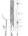
図3の最下段は、道路Rを走行中の自車両Cにおいて、時点T1でフェールが発生し運転支援の信頼性が低下、その後障害物OBをドライバが手動運転によって避ける場合の車両動作を示している。 The lowermost part of FIG. 3 shows the vehicle operation when a failure occurs at time T1 in the own vehicle C traveling on the road R and the reliability of driving support is lowered, and then the driver avoids the obstacle OB by manual driving. ing.
また図3の最上段の太い実線は、ドライバの操舵トルクTdを示している。図3のケースでは、時点T1の直後にフェールに気付いたドライバがステアリングホイール3の操作を開始、その後障害物OBを回避しようと時点T2前後から急激に操舵トルクを増加させたシーンを示している。
Also, the thick solid line at the top in FIG. 3 indicates the steering torque Td of the driver. The case of FIG. 3 shows a scene in which a driver who notices a failure immediately after time T1 starts operating the
時点T1直後は操舵トルク量も小さく、オーバーライド条件(|Td|>K(すなわち|Td|>Kf)は充足されず、車両動作も運転支援を継続する。時点T2前後では、閾値KがKnに固定されたままであれば、時点T2よりもある程度後の時点T3において|Td|>Knとなるまで、手動運転に切り換って操舵の権限がドライバ操作に移譲されることはない。これに対して、本実施形態では、図3の最上段に太い破線で示すように、フェールが発生した時点T1において閾値KがKnからKfに低減される。従って、T3よりも早いT2の時点で、オーバーライド条件としての|Td|>K(すなわち|Td|>Kf)が充足されて、ドライバ操作に権限委譲がなされる。すなわち、オーバーライドの運転状態へ円滑に移行して手動運転が可能になる。本実施形態では、このように、フェールが発生した場合に運転支援を中止させて手動運転に切り換える処理を、円滑に行うことができる。このため、最下段に矢印で示すように、自車両Cは障害物OBを容易に避けることができる。 Immediately after the time point T1, the steering torque amount is small, the override condition (| Td |> K (ie, | Td |> Kf) is not satisfied, and the vehicle operation continues to support driving. The threshold value K becomes Kn before and after the time point T2. If it remains fixed, the right to steer is not transferred to the driver operation until | Td |> Kn at a time T3 to some extent after the time T2. In the present embodiment, the threshold value K is reduced from Kn to Kf at the time T1 when the failure occurs, as indicated by the thick broken line in the uppermost part of Fig. 3. Therefore, the override is performed at the time T2 earlier than T3. The condition | Td |> K (that is, | Td |> Kf) is satisfied, and the authority is delegated to the driver operation, that is, the operation is smoothly shifted to the override operation state and manually performed. In this embodiment, in this embodiment, when a failure occurs, it is possible to smoothly perform the process of stopping driving support and switching to manual driving. Thus, the host vehicle C can easily avoid the obstacle OB.
(1B)しかも、本実施形態では、運転支援を中止させて手動運転(すなわちオーバーライド)に切り換えられたことや、運転支援が開始されたことが、S13又はS8の処理によって告知部5を介してドライバに告知される。このため、ドライバは自車両における権限移譲割合を容易に知ることができ、運転の安全性を一層向上させることができる。
(1B) In addition, in the present embodiment, the fact that the driving support is stopped and switched to the manual driving (that is, override), or that the driving support is started is notified via the
[2.第2実施形態]
[2−1.第1実施形態との相違点]
第2実施形態は、基本的な構成は第1実施形態と同様であるため、共通する構成については説明を省略し、相違点を中心に説明する。なお、第1実施形態と同じ符号は、同一の構成を示すものであって、先行する説明を参照する。
[2. Second Embodiment]
[2-1. Difference from the first embodiment]
Since the basic configuration of the second embodiment is the same as that of the first embodiment, the description of the common configuration will be omitted, and the description will focus on the differences. Note that the same reference numerals as those in the first embodiment indicate the same configuration, and the preceding description is referred to.
第2実施形態の運転支援装置101は、図4に示すように、制御部10が縮退制御部16を更に備えた点で、第1実施形態の運転支援装置1と相違する。この縮退制御部16も、CPUがプログラムを実行することで実現される機能の構成として、制御部10に設けられる。
As illustrated in FIG. 4, the driving
[2−2.処理]
制御部10が実行する運転支援処理においても、第1実施形態における処理に加えて、図5に示すS51,S52,S53の処理が、縮退制御部16による処理として実行される。図5に示す運転支援処理は、前記S51〜S53が追加された点を除いて、図3に示した第1実施形態における運転支援処理と同様である。
[2-2. processing]
Also in the driving support process executed by the
すなわち、本実施形態では、オーバーライド中でない場合にS7〜S9の処理による運転支援が実行されるのに先立って、S51にてフェールありか否かが判断される。この判断は、S1における判断結果をフラグ等の形態で記憶しておき、その判断結果を読み出すだけの処理であってもよく、S1とは独立して新たにフェールありか否かを判断する処理であってもよい。 In other words, in the present embodiment, it is determined in S51 whether or not there is a failure before the driving support by the processing of S7 to S9 is executed when the override is not in progress. This determination may be a process of storing the determination result in S1 in the form of a flag and the like and reading the determination result, or a process of determining whether or not there is a new failure independently of S1. It may be.
フェールなしの場合は、処理は前述のS7へ移行して第1実施形態と同様の処理が実行される。一方、フェールありの場合は、処理はS52へ移行する。S52では、図6に示すMAP1に基づき、係数AをKa_MIN(例えば0)からKa_MAX(例えば1.0)まで、時間の経過に応じて一次関数的に増加させる処理がなされる。なお、このMAP1における横軸の時間とは、フェールが発生してからの経過時間である。S52に続くS53では、S13と同様に運転支援が解除された旨の告知がなされて、処理は前述のS9へ移行する。 If there is no failure, the process proceeds to S7 described above, and the same process as in the first embodiment is executed. On the other hand, if there is a failure, the process proceeds to S52. In S52, a process of increasing the coefficient A from a Ka_MIN (for example, 0) to a Ka_MAX (for example, 1.0) in a linear function with the passage of time is performed based on MAP1 shown in FIG. The time on the horizontal axis in MAP1 is the elapsed time from the occurrence of a failure. In S53 following S52, notification that the driving assistance has been released is made in the same manner as in S13, and the process proceeds to S9 described above.
本実施形態では、フェールが発生したものの、操舵トルクTdの絶対値がまだ閾値K(すなわちKf)を超えていない状態では、S52,S53の処理が実行される。すなわち、フェール発生後の経過時間に応じて、係数Aが徐々に0から1.0まで増加する。その結果、図7に例示するように、前記運転支援(すなわちシステム制御)によってステアリングホイール3加えられるトルクTcが総トルクTに占める割合(すなわち権限委譲割合)は、フェールが発生した時点T5から徐々に減少する。図7の例では、操舵トルクTdの絶対値が閾値K(すなわちKf)を超えた時点T6では、すでにドライバ操作への権限委譲が完了している。すなわち、時点T6では、オーバーライドの運転状態へ完全に移行して手動運転が可能になっている。
In the present embodiment, when a failure has occurred but the absolute value of the steering torque Td has not yet exceeded the threshold value K (that is, Kf), the processes of S52 and S53 are executed. That is, the coefficient A gradually increases from 0 to 1.0 according to the elapsed time after the occurrence of the failure. As a result, as illustrated in FIG. 7, the ratio of the torque Tc applied by the
また、図8の例は、時点T7でフェールが発生し、係数Aが徐々に増加している最中の時点T8で、操舵トルクTdの絶対値が閾値Kを超える場合を示している。この例でも、操舵トルクTdの絶対値は、Knを超える時点T9よりも手前の時点T8で閾値K(すなわちKf)を超える。この場合、時点T7から徐々に権限委譲が始まるが、操舵トルクTdの絶対値が閾値Kを超えた時点T8からは急速に権限委譲が完了する。 Further, the example of FIG. 8 shows a case where the absolute value of the steering torque Td exceeds the threshold value K at time T8 when a failure occurs at time T7 and the coefficient A is gradually increasing. Also in this example, the absolute value of the steering torque Td exceeds the threshold value K (that is, Kf) at a time T8 before the time T9 when Kn is exceeded. In this case, authority delegation starts gradually from time T7, but authority delegation is completed rapidly from time T8 when the absolute value of the steering torque Td exceeds the threshold value K.
[2−3.効果]
以上詳述した第2実施形態によれば、前述した第1実施形態の効果(1A)(1B)に加え、以下の効果が得られる。
[2-3. effect]
According to the second embodiment described in detail above, the following effects can be obtained in addition to the effects (1A) and (1B) of the first embodiment described above.
(2A)本実施形態では、フェール発生時には、操舵トルクTdの絶対値が閾値Kを超えなくても、ステアリングホイール3に加えられる総トルクTに操舵トルクTdが反映される。すなわち、総トルクTに係る運転支援が縮退する。このため、ドライバによる操作がより早い時点から自車両の操舵状態に反映され、運転の安全性を一層向上させることができる。
(2A) In this embodiment, when a failure occurs, the steering torque Td is reflected in the total torque T applied to the
(2B)しかも、総トルクTに操舵トルクTdが反映される割合は時間の経過に応じて徐々に増加する。このため、運転支援を中止させて手動運転に切り換える処理は一層円滑に行われ、ドライバが違和感を感じるのを一層良好に抑制することができる。 (2B) Moreover, the ratio at which the steering torque Td is reflected in the total torque T gradually increases with the passage of time. For this reason, the process of canceling the driving support and switching to the manual driving is performed more smoothly, and the driver can be better suppressed from feeling uncomfortable.
[3.他の実施形態]
以上、本発明の実施形態について説明したが、本発明は前記実施形態に限定されることなく、種々の形態を採り得る。
[3. Other Embodiments]
As mentioned above, although embodiment of this invention was described, this invention can take a various form, without being limited to the said embodiment.
(3A)前記各実施形態では、ドライバがステアリングホイール3に加える操舵トルクTd(すなわち操作力)に対して閾値Kが設定されたが、これに限定されるものではない。例えば、ステアリングホイール3が何度以上切られたらオーバーライドへ移行するといったように、閾値Kが操舵角(すなわち操作量)に対して設定されてもよい。
(3A) In each of the embodiments described above, the threshold value K is set for the steering torque Td (that is, the operating force) applied by the driver to the
(3B)第2実施形態では、操舵トルクTdが総トルクTに反映される割合は、時間の経過に応じて徐々に一次関数的に増加しているが、これに限定されるものではない。例えば、前記割合は、ステップ状に増加してもよく、操舵トルクTdの絶対値が閾値Kを超えるまで例えばA=0.6等に応じた固定値とされてもよい。 (3B) In the second embodiment, the ratio at which the steering torque Td is reflected in the total torque T gradually increases in a linear function with the passage of time, but is not limited to this. For example, the ratio may increase stepwise, and may be a fixed value according to, for example, A = 0.6 until the absolute value of the steering torque Td exceeds the threshold value K.
(3C)前記各実施形態では、操作部の一例であるステアリングホイール3を介して車載器である操舵輪30を間接的に駆動したが、これに限定されるものではない。例えば、操舵輪30が直接駆動されてもよい。また、車載器がスロットルバルブやホイールシリンダ等である場合、加減速制御部29のように、それらを直接駆動してもよい。その場合、操作部としてのアクセルペダルやブレーキペダルは駆動されなくてもよい。また、操舵輪30が直接又は間接的に駆動される運転支援としても、白線逸脱を抑制する制御に限定されるものではなく、例えば縦列駐車等、種々の運転支援が考えられる。
(3C) In each of the above embodiments, the
(3D)前記実施形態における1つの構成要素が有する機能を複数の構成要素として分散させたり、複数の構成要素が有する機能を1つの構成要素に統合させたりしてもよい。また、前記実施形態の構成の一部を省略してもよい。また、前記実施形態の構成の少なくとも一部を、他の前記実施形態の構成に対して付加又は置換してもよい。なお、特許請求の範囲に記載した文言のみによって特定される技術思想に含まれるあらゆる態様が本発明の実施形態である。 (3D) The functions of one component in the embodiment may be distributed as a plurality of components, or the functions of a plurality of components may be integrated into one component. Moreover, you may abbreviate | omit a part of structure of the said embodiment. In addition, at least a part of the configuration of the embodiment may be added to or replaced with the configuration of the other embodiment. In addition, all the aspects included in the technical idea specified only by the wording described in the claim are embodiment of this invention.
(3E)上述した運転支援装置の他、当該運転支援装置を構成要素とするシステム、当該運転支援装置としてコンピュータを機能させるためのプログラム、このプログラムを記録した媒体、運転支援方法など、種々の形態で本発明を実現することもできる。 (3E) In addition to the above-described driving support device, various forms such as a system including the driving support device as a constituent element, a program for causing a computer to function as the driving support device, a medium recording the program, a driving support method, and the like Thus, the present invention can be realized.
1,101…運転支援装置 3…ステアリングホイール 5…告知部
7…支援スイッチ 10…制御部 11…状況認識部
12…運転支援部 13…切換制御部 14…閾値低減部
15…信頼検出部 16…縮退制御部 21…ミリ波レーダ
23…カメラ 25…操作検出部 27…ステア駆動部
30…操舵輪
DESCRIPTION OF SYMBOLS 1,101 ... Driving
Claims (4)
前記操作部が操作されていない状況下で、前記車載器を自動的に駆動する運転支援を実行する運転支援部(12)と、
前記操作部がドライバによって操作される操作力又は操作量を検出する操作検出部(25)と、
ドライバによる前記操作部に対する操作に応じて前記車載器が動作する運転状態を手動運転として、前記運転支援部が前記運転支援を実行している運転支援時に、前記操作検出部によって検出される操作力又は操作量が閾値を超えたとき、前記運転支援部による運転支援を中止させ、前記運転支援がなされる運転状態から前記手動運転に切り換える切換制御部(13)と、
前記運転支援部による運転支援の信頼度が低下したことを検出する信頼検出部(15)と、
前記運転支援時に、前記信頼検出部が前記信頼度の低下を検出したとき、前記閾値を低減させる閾値低減部(14)と、
前記運転支援時に、前記信頼検出部が前記信頼度の低下を検出している場合、前記閾値を超えない範囲の操作力又は操作量で前記操作部が操作されたときに、前記運転支援部による前記車載器の駆動に前記操作を少なくとも部分的に反映させる縮退制御部(16)と、
を備えた運転支援装置。 An operation unit (3) operated by a driver in order to operate the vehicle-mounted device (30) related to traveling of the vehicle to perform a driving operation;
A driving support unit (12) for performing driving support for automatically driving the vehicle-mounted device under a situation where the operation unit is not operated;
An operation detection unit (25) for detecting an operation force or an operation amount by which the operation unit is operated by a driver;
The operation force detected by the operation detection unit at the time of driving support in which the driving support unit is executing the driving support, with the driving state in which the vehicle-mounted device is operated according to the operation performed on the operation unit by the driver as manual driving. Alternatively, when the operation amount exceeds a threshold value, the switching control unit (13) that stops the driving support by the driving support unit and switches from the driving state in which the driving support is performed to the manual driving;
A reliability detection unit (15) for detecting that the reliability of the driving support by the driving support unit has decreased; and
A threshold value reduction unit (14) for reducing the threshold value when the reliability detection unit detects a decrease in the reliability during the driving support;
At the time of the driving support, when the reliability detecting unit detects a decrease in the reliability, when the operating unit is operated with an operating force or an operation amount in a range not exceeding the threshold, the driving support unit A degeneration control unit (16) for reflecting the operation at least partially in driving the vehicle-mounted device ;
A driving assistance device comprising:
請求項1に記載の運転支援装置。 The degeneration control unit gradually increases the rate at which the operation is reflected in the driving of the operation unit by the driving support unit as time passes when the reliability detection unit detects a decrease in the reliability. The driving support device according to claim 1 .
前記操作部はステアリングホイールであり、
前記運転支援部は、前記ステアリングホイールを駆動することによって前記操舵輪を駆動する
請求項1又は請求項2に記載の運転支援装置。 The on-vehicle device is a steering wheel,
The operation unit is a steering wheel;
The driving support unit, the driving support apparatus according to claim 1 or claim 2 for driving the steered wheels by driving the steering wheel.
更に備えた請求項1〜3のいずれか1項に記載の運転支援装置。 A notification unit (5) for notifying the driver that the switching control unit has stopped the driving support and switched to the manual driving;
The driving support device according to any one of claims 1 to 3 , further comprising:
Priority Applications (5)
| Application Number | Priority Date | Filing Date | Title |
|---|---|---|---|
| JP2016049616A JP6451674B2 (en) | 2016-03-14 | 2016-03-14 | Driving assistance device |
| CN201780017553.XA CN108778902B (en) | 2016-03-14 | 2017-03-13 | Driving support device, driving support method, and recording medium |
| DE112017001295.3T DE112017001295B4 (en) | 2016-03-14 | 2017-03-13 | Driving assistance apparatus, driving assistance method and recording medium |
| PCT/JP2017/009987 WO2017159617A1 (en) | 2016-03-14 | 2017-03-13 | Driving assistance device, driving assistance method, and recording medium |
| US16/084,389 US10569787B2 (en) | 2016-03-14 | 2017-03-13 | Driving support apparatus, driving support method, and recording medium |
Applications Claiming Priority (1)
| Application Number | Priority Date | Filing Date | Title |
|---|---|---|---|
| JP2016049616A JP6451674B2 (en) | 2016-03-14 | 2016-03-14 | Driving assistance device |
Publications (3)
| Publication Number | Publication Date |
|---|---|
| JP2017165128A JP2017165128A (en) | 2017-09-21 |
| JP2017165128A5 JP2017165128A5 (en) | 2018-02-08 |
| JP6451674B2 true JP6451674B2 (en) | 2019-01-16 |
Family
ID=59850267
Family Applications (1)
| Application Number | Title | Priority Date | Filing Date |
|---|---|---|---|
| JP2016049616A Active JP6451674B2 (en) | 2016-03-14 | 2016-03-14 | Driving assistance device |
Country Status (5)
| Country | Link |
|---|---|
| US (1) | US10569787B2 (en) |
| JP (1) | JP6451674B2 (en) |
| CN (1) | CN108778902B (en) |
| DE (1) | DE112017001295B4 (en) |
| WO (1) | WO2017159617A1 (en) |
Families Citing this family (5)
| Publication number | Priority date | Publication date | Assignee | Title |
|---|---|---|---|---|
| US11066096B2 (en) | 2018-03-06 | 2021-07-20 | Nissan Motor Co., Ltd. | Vehicle steering control method and vehicle steering control device |
| JP7084751B2 (en) * | 2018-03-23 | 2022-06-15 | 株式会社Subaru | Vehicle driving support device |
| JP6947130B2 (en) * | 2018-07-05 | 2021-10-13 | トヨタ自動車株式会社 | Vehicle running support device |
| JP7135931B2 (en) * | 2019-02-22 | 2022-09-13 | スズキ株式会社 | Vehicle travel control device |
| KR20220106358A (en) * | 2021-01-22 | 2022-07-29 | 주식회사 에이치엘클레무브 | Driver assistance system and control method thereof |
Family Cites Families (21)
| Publication number | Priority date | Publication date | Assignee | Title |
|---|---|---|---|---|
| JP2006117181A (en) * | 2004-10-25 | 2006-05-11 | Favess Co Ltd | Steering control device |
| JP4441909B2 (en) * | 2004-10-25 | 2010-03-31 | 株式会社デンソー | Vehicle control device |
| DE102006004772B4 (en) | 2006-02-02 | 2022-02-10 | Robert Bosch Gmbh | Driver assistance system and method for its control |
| JP4918818B2 (en) * | 2006-07-06 | 2012-04-18 | トヨタ自動車株式会社 | Vehicle travel support device |
| JP4386082B2 (en) * | 2007-02-20 | 2009-12-16 | トヨタ自動車株式会社 | Vehicle travel support device |
| DE102007062698A1 (en) | 2007-12-27 | 2009-07-02 | Volkswagen Ag | Method and device for traction aid for a motor vehicle driver |
| JP2009214680A (en) | 2008-03-10 | 2009-09-24 | Toyota Motor Corp | Lane keeping assist device, and control parameter changing method |
| JP2010173601A (en) * | 2009-02-02 | 2010-08-12 | Toyota Motor Corp | Driving support device |
| JP5267230B2 (en) * | 2009-03-10 | 2013-08-21 | 日産自動車株式会社 | Parking assistance device and parking assistance method |
| DE102011083039B4 (en) | 2011-09-20 | 2021-11-04 | Robert Bosch Gmbh | Device and method for operating a vehicle |
| JP6213033B2 (en) * | 2013-08-09 | 2017-10-18 | 株式会社デンソー | Motor control device |
| CN104551865A (en) * | 2013-10-17 | 2015-04-29 | 鸿富锦精密工业(深圳)有限公司 | Image measuring system and method |
| JP6314581B2 (en) * | 2014-03-24 | 2018-04-25 | 株式会社ジェイテクト | Steering control device |
| DE102014107194A1 (en) | 2014-05-22 | 2015-11-26 | Robert Bosch Automotive Steering Gmbh | Method for operating a steering system |
| CN104290745B (en) * | 2014-10-28 | 2017-02-01 | 奇瑞汽车股份有限公司 | Driving method of semi-automatic driving system for vehicle |
| EP3159853B1 (en) * | 2015-10-23 | 2019-03-27 | Harman International Industries, Incorporated | Systems and methods for advanced driver assistance analytics |
| JP6575818B2 (en) * | 2016-03-25 | 2019-09-18 | パナソニックIpマネジメント株式会社 | Driving support method, driving support device using the same, automatic driving control device, vehicle, driving support system, program |
| JP6690450B2 (en) * | 2016-07-19 | 2020-04-28 | 株式会社デンソー | Driving support device |
| US10220857B2 (en) * | 2017-02-23 | 2019-03-05 | Uber Technologies, Inc. | Vehicle control system |
| JP6543828B2 (en) * | 2017-06-01 | 2019-07-17 | 本田技研工業株式会社 | Vehicle control system, vehicle control method, and vehicle control program |
| JP6881175B2 (en) * | 2017-09-13 | 2021-06-02 | トヨタ自動車株式会社 | Driving support device and control method of driving support device |
-
2016
- 2016-03-14 JP JP2016049616A patent/JP6451674B2/en active Active
-
2017
- 2017-03-13 WO PCT/JP2017/009987 patent/WO2017159617A1/en active Application Filing
- 2017-03-13 US US16/084,389 patent/US10569787B2/en active Active
- 2017-03-13 CN CN201780017553.XA patent/CN108778902B/en active Active
- 2017-03-13 DE DE112017001295.3T patent/DE112017001295B4/en active Active
Also Published As
| Publication number | Publication date |
|---|---|
| US10569787B2 (en) | 2020-02-25 |
| WO2017159617A1 (en) | 2017-09-21 |
| JP2017165128A (en) | 2017-09-21 |
| CN108778902A (en) | 2018-11-09 |
| US20190084581A1 (en) | 2019-03-21 |
| CN108778902B (en) | 2021-05-14 |
| DE112017001295B4 (en) | 2022-08-04 |
| DE112017001295T5 (en) | 2018-12-06 |
Similar Documents
| Publication | Publication Date | Title |
|---|---|---|
| JP6451674B2 (en) | Driving assistance device | |
| JP6493272B2 (en) | Driving support device | |
| US10899381B2 (en) | Steering control device and control method for steering control device | |
| WO2016181725A1 (en) | Automatic driving control device | |
| EP3124361B1 (en) | Parking assistance device, parking assistance method, and non-transitory computer readable medium storing program | |
| JP6547394B2 (en) | Vehicle braking control device | |
| WO2015186648A1 (en) | Vehicle travel control device | |
| JP6228581B2 (en) | Stop control device | |
| JP6119634B2 (en) | Vehicle automatic operation control method | |
| JP6427155B2 (en) | Traveling control device and traveling control method | |
| JP6551368B2 (en) | Vehicle control device | |
| JP2023033411A (en) | Control system of vehicle, control method of vehicle and program | |
| JP2008189139A (en) | Driving support device for vehicle | |
| JP5967239B1 (en) | Steering reaction force control device | |
| JPH11310147A (en) | Vehicular steering control device | |
| KR20150021401A (en) | Active Rear Wheel Steering Apparatus Control Method | |
| JP6369477B2 (en) | Driving assistance device | |
| JP2004352110A (en) | Travel supporting device for vehicle | |
| JP2014024462A (en) | Parking support device | |
| JP4200943B2 (en) | Driving support device | |
| JP6942144B2 (en) | Driving support device and driving support method | |
| WO2017110914A1 (en) | Vehicle control device | |
| WO2018092229A1 (en) | Driving assist device and driving assist method | |
| JP2018197005A (en) | Parking support system and parking support method | |
| US20240101194A1 (en) | Driving assistance system |
Legal Events
| Date | Code | Title | Description |
|---|---|---|---|
| A521 | Request for written amendment filed |
Free format text: JAPANESE INTERMEDIATE CODE: A523 Effective date: 20171220 |
|
| A621 | Written request for application examination |
Free format text: JAPANESE INTERMEDIATE CODE: A621 Effective date: 20171226 |
|
| TRDD | Decision of grant or rejection written | ||
| A01 | Written decision to grant a patent or to grant a registration (utility model) |
Free format text: JAPANESE INTERMEDIATE CODE: A01 Effective date: 20181113 |
|
| A61 | First payment of annual fees (during grant procedure) |
Free format text: JAPANESE INTERMEDIATE CODE: A61 Effective date: 20181126 |
|
| R151 | Written notification of patent or utility model registration |
Ref document number: 6451674 Country of ref document: JP Free format text: JAPANESE INTERMEDIATE CODE: R151 |
|
| R250 | Receipt of annual fees |
Free format text: JAPANESE INTERMEDIATE CODE: R250 |
|
| R250 | Receipt of annual fees |
Free format text: JAPANESE INTERMEDIATE CODE: R250 |
|
| R250 | Receipt of annual fees |
Free format text: JAPANESE INTERMEDIATE CODE: R250 |