JP6451515B2 - Ignition coil for internal combustion engines - Google Patents
Ignition coil for internal combustion engines Download PDFInfo
- Publication number
- JP6451515B2 JP6451515B2 JP2015116114A JP2015116114A JP6451515B2 JP 6451515 B2 JP6451515 B2 JP 6451515B2 JP 2015116114 A JP2015116114 A JP 2015116114A JP 2015116114 A JP2015116114 A JP 2015116114A JP 6451515 B2 JP6451515 B2 JP 6451515B2
- Authority
- JP
- Japan
- Prior art keywords
- coil
- connector
- terminal body
- lead wire
- fitting recess
- Prior art date
- Legal status (The legal status is an assumption and is not a legal conclusion. Google has not performed a legal analysis and makes no representation as to the accuracy of the status listed.)
- Active
Links
- 238000002485 combustion reaction Methods 0.000 title claims description 27
- WABPQHHGFIMREM-UHFFFAOYSA-N lead(0) Chemical compound [Pb] WABPQHHGFIMREM-UHFFFAOYSA-N 0.000 claims description 107
- 239000000463 material Substances 0.000 claims description 10
- 230000000694 effects Effects 0.000 description 9
- 239000004020 conductor Substances 0.000 description 7
- 239000002184 metal Substances 0.000 description 7
- 238000005452 bending Methods 0.000 description 6
- 238000009413 insulation Methods 0.000 description 6
- 230000002093 peripheral effect Effects 0.000 description 5
- 229920005989 resin Polymers 0.000 description 5
- 239000011347 resin Substances 0.000 description 5
- 239000003990 capacitor Substances 0.000 description 4
- 230000009466 transformation Effects 0.000 description 3
- 229910000906 Bronze Inorganic materials 0.000 description 2
- OAICVXFJPJFONN-UHFFFAOYSA-N Phosphorus Chemical compound [P] OAICVXFJPJFONN-UHFFFAOYSA-N 0.000 description 2
- 239000010974 bronze Substances 0.000 description 2
- 210000000078 claw Anatomy 0.000 description 2
- KUNSUQLRTQLHQQ-UHFFFAOYSA-N copper tin Chemical compound [Cu].[Sn] KUNSUQLRTQLHQQ-UHFFFAOYSA-N 0.000 description 2
- 238000010586 diagram Methods 0.000 description 2
- 238000003825 pressing Methods 0.000 description 2
- 238000004080 punching Methods 0.000 description 2
- 238000004804 winding Methods 0.000 description 2
- 239000003822 epoxy resin Substances 0.000 description 1
- 230000005669 field effect Effects 0.000 description 1
- 238000012423 maintenance Methods 0.000 description 1
- 238000000034 method Methods 0.000 description 1
- 238000000465 moulding Methods 0.000 description 1
- 229920000647 polyepoxide Polymers 0.000 description 1
- 230000001105 regulatory effect Effects 0.000 description 1
- 230000008646 thermal stress Effects 0.000 description 1
Images


Classifications
-
- F—MECHANICAL ENGINEERING; LIGHTING; HEATING; WEAPONS; BLASTING
- F02—COMBUSTION ENGINES; HOT-GAS OR COMBUSTION-PRODUCT ENGINE PLANTS
- F02P—IGNITION, OTHER THAN COMPRESSION IGNITION, FOR INTERNAL-COMBUSTION ENGINES; TESTING OF IGNITION TIMING IN COMPRESSION-IGNITION ENGINES
- F02P13/00—Sparking plugs structurally combined with other parts of internal-combustion engines
-
- F—MECHANICAL ENGINEERING; LIGHTING; HEATING; WEAPONS; BLASTING
- F02—COMBUSTION ENGINES; HOT-GAS OR COMBUSTION-PRODUCT ENGINE PLANTS
- F02P—IGNITION, OTHER THAN COMPRESSION IGNITION, FOR INTERNAL-COMBUSTION ENGINES; TESTING OF IGNITION TIMING IN COMPRESSION-IGNITION ENGINES
- F02P17/00—Testing of ignition installations, e.g. in combination with adjusting; Testing of ignition timing in compression-ignition engines
- F02P17/12—Testing characteristics of the spark, ignition voltage or current
-
- F—MECHANICAL ENGINEERING; LIGHTING; HEATING; WEAPONS; BLASTING
- F02—COMBUSTION ENGINES; HOT-GAS OR COMBUSTION-PRODUCT ENGINE PLANTS
- F02P—IGNITION, OTHER THAN COMPRESSION IGNITION, FOR INTERNAL-COMBUSTION ENGINES; TESTING OF IGNITION TIMING IN COMPRESSION-IGNITION ENGINES
- F02P3/00—Other installations
- F02P3/02—Other installations having inductive energy storage, e.g. arrangements of induction coils
- F02P3/04—Layout of circuits
- F02P3/0407—Opening or closing the primary coil circuit with electronic switching means
-
- H—ELECTRICITY
- H01—ELECTRIC ELEMENTS
- H01F—MAGNETS; INDUCTANCES; TRANSFORMERS; SELECTION OF MATERIALS FOR THEIR MAGNETIC PROPERTIES
- H01F27/00—Details of transformers or inductances, in general
- H01F27/02—Casings
- H01F27/022—Encapsulation
-
- H—ELECTRICITY
- H01—ELECTRIC ELEMENTS
- H01F—MAGNETS; INDUCTANCES; TRANSFORMERS; SELECTION OF MATERIALS FOR THEIR MAGNETIC PROPERTIES
- H01F27/00—Details of transformers or inductances, in general
- H01F27/28—Coils; Windings; Conductive connections
- H01F27/30—Fastening or clamping coils, windings, or parts thereof together; Fastening or mounting coils or windings on core, casing, or other support
- H01F27/306—Fastening or mounting coils or windings on core, casing or other support
-
- H—ELECTRICITY
- H01—ELECTRIC ELEMENTS
- H01F—MAGNETS; INDUCTANCES; TRANSFORMERS; SELECTION OF MATERIALS FOR THEIR MAGNETIC PROPERTIES
- H01F38/00—Adaptations of transformers or inductances for specific applications or functions
- H01F38/12—Ignition, e.g. for IC engines
-
- H—ELECTRICITY
- H01—ELECTRIC ELEMENTS
- H01R—ELECTRICALLY-CONDUCTIVE CONNECTIONS; STRUCTURAL ASSOCIATIONS OF A PLURALITY OF MUTUALLY-INSULATED ELECTRICAL CONNECTING ELEMENTS; COUPLING DEVICES; CURRENT COLLECTORS
- H01R4/00—Electrically-conductive connections between two or more conductive members in direct contact, i.e. touching one another; Means for effecting or maintaining such contact; Electrically-conductive connections having two or more spaced connecting locations for conductors and using contact members penetrating insulation
- H01R4/28—Clamped connections, spring connections
- H01R4/48—Clamped connections, spring connections utilising a spring, clip, or other resilient member
- H01R4/489—Clamped connections, spring connections utilising a spring, clip, or other resilient member spring force increased by screw, cam, wedge, or other fastening means
-
- H—ELECTRICITY
- H01—ELECTRIC ELEMENTS
- H01R—ELECTRICALLY-CONDUCTIVE CONNECTIONS; STRUCTURAL ASSOCIATIONS OF A PLURALITY OF MUTUALLY-INSULATED ELECTRICAL CONNECTING ELEMENTS; COUPLING DEVICES; CURRENT COLLECTORS
- H01R13/00—Details of coupling devices of the kinds covered by groups H01R12/70 or H01R24/00 - H01R33/00
- H01R13/02—Contact members
- H01R13/03—Contact members characterised by the material, e.g. plating, or coating materials
Landscapes
- Engineering & Computer Science (AREA)
- Power Engineering (AREA)
- Chemical & Material Sciences (AREA)
- Combustion & Propulsion (AREA)
- Mechanical Engineering (AREA)
- General Engineering & Computer Science (AREA)
- Ignition Installations For Internal Combustion Engines (AREA)
Description
本発明は、内燃機関用の点火コイルに関する。 The present invention relates to an ignition coil for an internal combustion engine.
内燃機関用の点火コイルとして、一次コイル及び二次コイルと、電源用コネクタ端子とを有するものがある。かかる構成の点火コイルにおいて、二次コイルの低圧側と電源用コネクタ端子との間にダイオードを接続してなる構成が開示されている(特許文献1)。特許文献1に開示された点火コイルにおいては、電源用コネクタ端子の端部に設けたスリットに、ダイオードのリード線が圧入されている。なお、ダイオードに代えて、単なる導体配線によって二次コイルの低圧側と電源用コネクタ端子との間を接続する構成もある。 Some ignition coils for internal combustion engines have a primary coil and a secondary coil, and a power connector terminal. In the ignition coil having such a configuration, a configuration is disclosed in which a diode is connected between the low voltage side of the secondary coil and the power connector terminal (Patent Document 1). In the ignition coil disclosed in Patent Document 1, a lead wire of a diode is press-fitted into a slit provided at an end portion of a power connector terminal. There is also a configuration in which the low voltage side of the secondary coil and the power connector terminal are connected by simple conductor wiring instead of the diode.
しかしながら、上記特許文献1に開示された点火コイルにおいては、以下の問題がある。
ダイオード等の接続部品と電源用コネクタ端子との接続作業は容易となるが、接続部品と二次コイルとの間の接続については、上記のような圧入構造ではないため、接続作業を容易にすることができない。
However, the ignition coil disclosed in Patent Document 1 has the following problems.
The connection work between the connection component such as a diode and the power connector terminal is easy, but the connection work between the connection component and the secondary coil is not a press-fit structure as described above, so the connection work is easy. I can't.
また、コネクタ端子のスリットにリード線を圧入する構成は、スリットに面するコネクタ端子のエッジがリード線に食い込むことが懸念される。例えば、コネクタ端子が金属板をプレス打ち抜きすることにより形成されていると、スリットに面する部分にもエッジが形成され、このエッジがリード線に食い込むおそれがある。この場合、リード線が削れて導電性異物が発生する。この導電性異物が点火コイルのケースの内部に散乱して、一次コイル及び二次コイルの周囲に充填されるモールド樹脂内に混入すると、モールド樹脂の絶縁性が低下するおそれが懸念される。 Further, the configuration in which the lead wire is press-fitted into the slit of the connector terminal is concerned that the edge of the connector terminal facing the slit may bite into the lead wire. For example, if the connector terminal is formed by press punching a metal plate, an edge is also formed in a portion facing the slit, and this edge may bite into the lead wire. In this case, the lead wire is shaved and conductive foreign matter is generated. If this conductive foreign material is scattered inside the case of the ignition coil and mixed in the mold resin filled around the primary coil and the secondary coil, there is a concern that the insulation of the mold resin may be lowered.
また、コネクタ端子のエッジがリード線に食い込むと、リード線にノッチが生じることとなる。この場合、ノッチに冷熱ストレスが集中するなどにより、リード線の耐久性の低下の原因となりうる。 Further, when the edge of the connector terminal bites into the lead wire, a notch is generated in the lead wire. In this case, the thermal stress is concentrated on the notch, which may cause a decrease in durability of the lead wire.
本発明は、かかる背景に鑑みてなされたものであり、接続部品を容易に組み付けることができると共に、絶縁性、耐久性に優れた内燃機関用の点火コイルを提供しようとするものである。 The present invention has been made in view of such a background, and an object of the present invention is to provide an ignition coil for an internal combustion engine that can easily assemble a connection component and is excellent in insulation and durability.
本発明の一態様は、互いに磁気的に結合された一次コイル及び二次コイルと、
該二次コイルの低圧側に接続されたコイル端子体と、
外部機器に電気的に接続されるコネクタ端子体と、
上記コイル端子体と上記コネクタ端子体とに懸架されるように接続される接続部品と、を有し、
該接続部品は、上記コイル端子体に接続される線材からなるコイル側リード線と、上記コネクタ端子体に接続される線材からなるコネクタ側リード線とを有し、
上記コイル端子体は、上記コイル側リード線を嵌入させるコイル側嵌合凹部を有し、該コイル側嵌合凹部の内側端面は、内側に向かって凸状の曲面に形成されており、
上記コネクタ端子体は、上記コネクタ側リード線を嵌入させるコネクタ側嵌合凹部を有し、該コネクタ側嵌合凹部の内側端面は、内側に向かって凸状の曲面に形成されており、
上記コイル側リード線は、該コイル側リード線の長手方向と直交する方向に上記コイル側嵌合凹部に圧入されており、
上記コネクタ側リード線は、該コネクタ側リード線の長手方向と直交する方向に上記コネクタ側嵌合凹部に圧入されており、
上記コイル端子体は、線材によって構成されており、
上記コイル端子体は、上記二次コイルが巻回されたボビンに設けられた端子保持部に保持されており、
上記端子保持部は、上記コイル側嵌合凹部の広がりを規制する変形規制部を備えていることを特徴とする内燃機関用の点火コイルにある。
本発明の他の態様は、互いに磁気的に結合された一次コイル及び二次コイルと、
該二次コイルの低圧側に接続されたコイル端子体と、
外部機器に電気的に接続されるコネクタ端子体と、
上記コイル端子体と上記コネクタ端子体とに懸架されるように接続される接続部品と、を有し、
該接続部品は、上記コイル端子体に接続される線材からなるコイル側リード線と、上記コネクタ端子体に接続される線材からなるコネクタ側リード線とを有し、
上記コイル端子体は、上記コイル側リード線を嵌入させるコイル側嵌合凹部を有し、該コイル側嵌合凹部の内側端面は、内側に向かって凸状の曲面に形成されており、
上記コネクタ端子体は、上記コネクタ側リード線を嵌入させるコネクタ側嵌合凹部を有し、該コネクタ側嵌合凹部の内側端面は、内側に向かって凸状の曲面に形成されており、
上記コイル側リード線は、該コイル側リード線の長手方向と直交する方向に上記コイル側嵌合凹部に圧入されており、
上記コネクタ側リード線は、該コネクタ側リード線の長手方向と直交する方向に上記コネクタ側嵌合凹部に圧入されており、
上記コイル側嵌合凹部の深さ方向と上記コネクタ側嵌合凹部の深さ方向とは、互いに同一方向であることを特徴とする内燃機関用の点火コイルにある。
本発明のさらに他の態様は、互いに磁気的に結合された一次コイル及び二次コイルと、
該二次コイルの低圧側に接続されたコイル端子体と、
外部機器に電気的に接続されるコネクタ端子体と、
上記コイル端子体と上記コネクタ端子体とに懸架されるように接続される接続部品と、を有し、
該接続部品は、上記コイル端子体に接続される線材からなるコイル側リード線と、上記コネクタ端子体に接続される線材からなるコネクタ側リード線とを有し、
上記コイル端子体は、上記コイル側リード線を嵌入させるコイル側嵌合凹部を有し、該コイル側嵌合凹部の内側端面は、内側に向かって凸状の曲面に形成されており、
上記コネクタ端子体は、上記コネクタ側リード線を嵌入させるコネクタ側嵌合凹部を有し、該コネクタ側嵌合凹部の内側端面は、内側に向かって凸状の曲面に形成されており、
上記コイル側リード線は、該コイル側リード線の長手方向と直交する方向に上記コイル側嵌合凹部に圧入されており、
上記コネクタ側リード線は、該コネクタ側リード線の長手方向と直交する方向に上記コネクタ側嵌合凹部に圧入されており、
上記コネクタ端子体は、線材によって構成されていることを特徴とする内燃機関用の点火コイルにある。
One aspect of the present invention includes a primary coil and a secondary coil that are magnetically coupled to each other;
A coil terminal connected to the low voltage side of the secondary coil;
A connector terminal body electrically connected to an external device;
A connection component connected to be suspended from the coil terminal body and the connector terminal body,
The connection component has a coil side lead wire made of a wire connected to the coil terminal body and a connector side lead wire made of a wire connected to the connector terminal body,
The coil terminal body has a coil-side fitting recess into which the coil-side lead wire is fitted, and an inner end surface of the coil-side fitting recess is formed into a convex curved surface toward the inside,
The connector terminal body has a connector-side fitting recess into which the connector-side lead wire is inserted, and an inner end surface of the connector-side fitting recess is formed into a convex curved surface toward the inside,
The coil side lead wire is press-fitted into the coil side fitting recess in a direction perpendicular to the longitudinal direction of the coil side lead wire,
The connector-side lead wire is press-fitted into the connector-side fitting recess in a direction orthogonal to the longitudinal direction of the connector-side lead wire ,
The coil terminal body is composed of a wire,
The coil terminal body is held by a terminal holding portion provided on a bobbin around which the secondary coil is wound,
The terminal holding part is an ignition coil for an internal combustion engine, characterized in that it includes a deformation restricting part for restricting the spread of the coil side fitting recess .
Another aspect of the invention comprises a primary coil and a secondary coil that are magnetically coupled to each other;
A coil terminal connected to the low voltage side of the secondary coil;
A connector terminal body electrically connected to an external device;
A connection component connected to be suspended from the coil terminal body and the connector terminal body,
The connection component has a coil side lead wire made of a wire connected to the coil terminal body and a connector side lead wire made of a wire connected to the connector terminal body,
The coil terminal body has a coil-side fitting recess into which the coil-side lead wire is fitted, and an inner end surface of the coil-side fitting recess is formed into a convex curved surface toward the inside,
The connector terminal body has a connector-side fitting recess into which the connector-side lead wire is inserted, and an inner end surface of the connector-side fitting recess is formed into a convex curved surface toward the inside,
The coil side lead wire is press-fitted into the coil side fitting recess in a direction perpendicular to the longitudinal direction of the coil side lead wire,
The connector-side lead wire is press-fitted into the connector-side fitting recess in a direction orthogonal to the longitudinal direction of the connector-side lead wire,
The depth direction of the coil-side fitting recess and the depth direction of the connector-side fitting recess are in the same direction as each other in the ignition coil for an internal combustion engine.
Yet another aspect of the present invention provides a primary coil and a secondary coil that are magnetically coupled to each other;
A coil terminal connected to the low voltage side of the secondary coil;
A connector terminal body electrically connected to an external device;
A connection component connected to be suspended from the coil terminal body and the connector terminal body,
The connection component has a coil side lead wire made of a wire connected to the coil terminal body and a connector side lead wire made of a wire connected to the connector terminal body,
The coil terminal body has a coil-side fitting recess into which the coil-side lead wire is fitted, and an inner end surface of the coil-side fitting recess is formed into a convex curved surface toward the inside,
The connector terminal body has a connector-side fitting recess into which the connector-side lead wire is inserted, and an inner end surface of the connector-side fitting recess is formed into a convex curved surface toward the inside,
The coil side lead wire is press-fitted into the coil side fitting recess in a direction perpendicular to the longitudinal direction of the coil side lead wire,
The connector-side lead wire is press-fitted into the connector-side fitting recess in a direction orthogonal to the longitudinal direction of the connector-side lead wire,
The connector terminal body is an ignition coil for an internal combustion engine, which is made of a wire material.
上記内燃機関用の点火コイルにおいて、上記接続部品のコイル側リード線はコイル端子体のコイル側嵌合凹部に圧入され、接続部品のコネクタ側リード線はコネクタ端子体のコネクタ側嵌合凹部に圧入されている。そのため、接続部品をコイル端子体及びコネクタ端子体に組み付ける作業が容易となる。以下において、コイル端子体及びコネクタ端子体を、単に「端子体」ということもある。同様に、コイル側嵌合凹部及びコネクタ側嵌合凹部を、単に「嵌合凹部」ということもあり、コイル側リード端子及びコネクタ側リード線を、単に「リード線」ということもある。 In the ignition coil for an internal combustion engine, the coil lead wire of the connecting part is press-fitted into the coil side fitting recess of the coil terminal body, and the connector side lead wire of the connecting part is press-fitted into the connector side fitting recess of the connector terminal body. Has been. Therefore, the work of assembling the connection component to the coil terminal body and the connector terminal body is facilitated. Hereinafter, the coil terminal body and the connector terminal body may be simply referred to as “terminal bodies”. Similarly, the coil-side fitting concave portion and the connector-side fitting concave portion may be simply referred to as “fitting concave portion”, and the coil-side lead terminal and connector-side lead wire may be simply referred to as “lead wire”.
また、各嵌合凹部の内側端面は、それぞれ内側に向かって凸状の曲面に形成されている。そのため、各リード線をそれぞれ各嵌合凹部に圧入する際に、リード線に削れが生じることを防ぐことができる。すなわち、上記の圧入時における、リード線と端子体との接触が、曲面同士の接触となる。そのため、リード線に削れが生じることを防ぐことができる。その結果、導電性異物が点火コイル内に散乱することを防ぐことができ、絶縁性の低下を防ぐことができる。また、リード線にノッチが形成されることを防ぐことができ、耐久性を向上させることができる。 Further, the inner end face of each fitting recess is formed in a curved surface that is convex toward the inside. Therefore, when the lead wires are press-fitted into the fitting recesses, the lead wires can be prevented from being scraped. That is, the contact between the lead wire and the terminal body at the time of the above press-fitting becomes the contact between the curved surfaces. Therefore, it is possible to prevent the lead wire from being scraped. As a result, it is possible to prevent the conductive foreign matter from being scattered in the ignition coil, and it is possible to prevent a decrease in insulation. Further, it is possible to prevent the notch from being formed in the lead wire, and to improve the durability.
以上のごとく、上記態様によれば、接続部品を容易に組み付けることができると共に、絶縁性、耐久性に優れた内燃機関用の点火コイルを提供することができる。 As described above, according to the above aspect, it is possible to provide an ignition coil for an internal combustion engine that can easily assemble a connection component and is excellent in insulation and durability.
(実施形態1)
内燃機関用の点火コイルの実施形態につき、図1〜図7を用いて説明する。
本実施形態の点火コイル1は、図1に示すごとく、互いに磁気的に結合された一次コイル21及び二次コイル22と、二次コイル22の低圧側に接続されたコイル端子体3と、外部機器に電気的に接続されるコネクタ端子体4と、コイル端子体3とコネクタ端子体4とに懸架されるように接続される接続部品5と、を有する。
(Embodiment 1)
An embodiment of an ignition coil for an internal combustion engine will be described with reference to FIGS.
As shown in FIG. 1, the ignition coil 1 of the present embodiment includes a
図2〜図4に示すごとく、接続部品5は、コイル端子体3に接続される線材からなるコイル側リード線51と、コネクタ端子体4に接続される線材からなるコネクタ側リード線52とを有する。
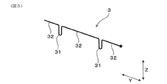
図3〜図5に示すごとく、コイル端子体3は、コイル側リード線51を嵌入させるコイル側嵌合凹部31を有する。コイル側嵌合凹部31の内側端面311は、内側に向かって凸状の曲面に形成されている。
As shown in FIGS. 2 to 4, the connecting
As shown in FIGS. 3 to 5, the
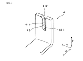
図3、図4、図6に示すごとく、コネクタ端子体4は、コネクタ側リード線52を嵌入させるコネクタ側嵌合凹部41を有する。コネクタ側嵌合凹部41の内側端面411は、内側に向かって凸状の曲面に形成されている。
図2、図4に示すごとく、コイル側リード線51は、コイル側リード線51の長手方向と直交する方向にコイル側嵌合凹部31に圧入されている。コネクタ側リード線52は、コネクタ側リード線52の長手方向と直交する方向にコネクタ側嵌合凹部41に圧入されている。
As shown in FIGS. 3, 4, and 6, the
As shown in FIGS. 2 and 4, the coil-
点火コイル1は、自動車、コージェネレーション等の内燃機関に設置されるスパークプラグ(図示略)に接続され、スパークプラグに高電圧を印加する手段として用いられる。
図1に示すごとく、点火コイル1は、一次コイル21及び二次コイル22等を収容するケース11を有する。ケース11は、一次コイル21及び二次コイル22の軸方向(以下において、適宜「軸方向X」という。)と直交する方向(以下において、適宜「上下方向Z」という。)の一方に開口面を有する。以下において、適宜、ケース11の開口面側を上側といい、その反対側を下側というが、特に上下方向を限定するものではない。
The ignition coil 1 is connected to a spark plug (not shown) installed in an internal combustion engine such as an automobile or a cogeneration system, and is used as means for applying a high voltage to the spark plug.
As shown in FIG. 1, the ignition coil 1 includes a case 11 that houses a
一次コイル21及び二次コイル22の内周側と外周側とには、それぞれ、中心コア121と外周コア122とが配されている。また、二次コイル22は、一次コイル21の外周側において、樹脂製のボビン6に巻回されている。
A
ケース11には、外部機器としてのバッテリに接続される外部コネクタ13が設けられている。コネクタ端子体4は、その外側の端部49を、外部コネクタ13内に配置してなる。また、ケース11内には、一次コイル21への通電のオンオフを切り替えるためのイグナイタ14が配置されている。
The case 11 is provided with an
ケース11内には、一次コイル21及び二次コイル22、中心コア121、外周コア122、イグナイタ14、コイル端子体3、コネクタ端子体4、接続部品5が収容され、これらを封止するようにモールド樹脂15が充填されている。モールド樹脂15は、例えばエポキシ樹脂からなる。
In the case 11, a
コイル端子体3は、図4、図5に示すごとく、線材によって構成されている。すなわち、線材を屈曲形成することにより、コイル側嵌合凹部31を備えたコイル端子体3が形成されている。コイル端子体3を構成する線材は、長手方向に直交する断面の形状が円形状の導体線材である。また、この線材は、例えば、バネ用リン青銅からなる。また、線材は、引き抜き加工により得られる。また、線材において、少なくともコイル側リード線51と接触する部分は、絶縁被膜等によって被覆されておらず、金属が露出した状態となっている。
As shown in FIGS. 4 and 5, the
また、コイル端子体3には、二次コイル22の巻線における低圧側の端部が接続されている。すなわち、二次コイル22の巻線は、スパークプラグ側に接続される高圧側の端部と、その反対側の低圧側の端部とを有し、この低圧側の端部にコイル端子体3が接続されている。図5に示すごとく、コイル端子体3は、軸方向X及び上下方向Zの双方に直交する横方向Yに延びる横方向部32と、該横方向部32の一部から下方へ垂下するように形成されたコイル側嵌合凹部31とを有する。コイル側嵌合凹部31は、上方に開口した状態の略U字形状に形成されている。コイル端子体3は、コイル側嵌合凹部31を2つ有し、図2に示すごとく、一方のコイル側嵌合凹部31に、接続部品5のコイル側リード線51が圧入されている。
Further, the
コイル端子体3は、二次コイル22が巻回されたボビン6に設けられた端子保持部61に保持されている。端子保持部61は、ボビン6における外部コネクタ13に近い側の、軸方向Xの端部に設けられている。端子保持部61は、一対の爪部611を有する。コイル端子体3は、横方向Yの両端部を一対の爪部611にそれぞれ係合させることにより、端子保持部61に保持されている。
The
コネクタ端子体4は、板状体によって構成されている。すなわち、金属板をプレス打ち抜きするとともに、曲げ加工することにより、コネクタ側嵌合凹部41を備えたコネクタ端子体4が形成されている。本実施形態において、コネクタ側嵌合凹部41は、図6に示すごとく、金属板の一部に設けたスリットによって形成されている。そして、コネクタ側嵌合凹部41における内側端面411は、凸状の曲面となっている。すなわち、内側端面411は、コネクタ側嵌合凹部41の深さ方向に直交する断面の形状が曲線状となる曲面である。
The
この凸状の曲面は、例えば、金属板をプレス打ち抜きした後、スリットに面する端面の角部を金属板の厚み方向の両側からプレス面押し加工して端面を曲面状に成形することにより、得ることができる。
また、コネクタ側嵌合凹部41の深さ方向における開口側端部(すなわち、上端部)には、開口側(すなわち、上方)へ向かうほど広がる拡開部412が形成されている。
For example, the convex curved surface is formed by pressing a metal plate and then pressing the corners of the end surface facing the slit from both sides in the thickness direction of the metal plate to form the end surface into a curved shape. Can be obtained.
In addition, at the opening side end portion (that is, the upper end portion) in the depth direction of the connector-side fitting
図2に示すごとく、コイル側嵌合凹部31の深さ方向とコネクタ側嵌合凹部41の深さ方向とは、互いに同一方向である。本実施形態においては、コイル側嵌合凹部31の深さ方向とコネクタ側嵌合凹部41の深さ方向とは、いずれも上下方向Zである。
As shown in FIG. 2, the depth direction of the coil-side
本実施形態において、接続部品5はダイオードである。図3、図4に示すごとく、接続部品5は、ダイオードの素子部50から、コイル側リード線51とコネクタ側リード線52とを、互いに反対方向に突出してなる。リード線51、52を構成する線材は、長手方向に直交する断面の形状が円形状の導体線材である。また、この線材は、例えば、りん青銅からなる。また、線材は、引き抜き加工により得られる。また、線材は、少なくともコイル端子3又はコネクタ端子4と接触する部分は、絶縁被膜等によって被覆されておらず、金属が露出した状態となっている。
In the present embodiment, the
点火コイル1は、図7の回路図に示すごとく、スパークプラグ101と共に、内燃機関の点火装置の一部を構成する。点火コイル1における一次コイル21の一端は、バッテリ102の正極に接続され、一次コイル21の他端はイグナイタ14を介して、バッテリ102の負極に接続されている。イグナイタ14は、例えば、IGBT(絶縁ゲートバイポーラトランジスタ)、MOSFET(MOS型電界効果トランジスタ
)を用いて構成することができる。また、二次コイル22の高圧側は、スパークプラグ101に接続されており、二次コイル22の低圧側は、ダイオード5d(すなわち、接続部品5)を介してバッテリ102の正極に接続されている。
As shown in the circuit diagram of FIG. 7, the ignition coil 1 constitutes a part of an ignition device for an internal combustion engine together with the
ダイオード5dは、コネクタ端子体4を介して、バッテリ102の正極と電気的に接続される。また、ダイオード5dは、コイル端子体3を介して、二次コイル22の低圧側に電気的に接続されている。また、ダイオード5dのアノードがコイル端子体3に接続され、カソードがコネクタ端子体4に接続されている。すなわち、ダイオード5dのアノードがコイル側リード線51であり、カソードがコネクタ側リード線52である。
The diode 5 d is electrically connected to the positive electrode of the
上記のように構成された点火装置においては、イグナイタ14のスイッチングによって、一次コイル21への通電のオンオフを切り替えるよう構成されている。そして、一次コイル21への通電をオン状態からオフ状態に切り替える際に、二次コイル22に誘起される電圧が、スパークプラグ101に印加されるよう構成されている。この二次電圧が二次コイル22に誘起される際、二次コイル22には、スパークプラグ101側である高圧側から、ダイオード5d側である低圧側へ向かって電流が流れる。
The ignition device configured as described above is configured to switch on / off of energization to the
ダイオード5dは、上記の電流の方向と逆向きの逆電流が、二次コイル22に生じることを防いでいる。すなわち、ダイオード5dは、一次コイル21への通電をオフ状態からオン状態に切り替えた際に二次コイル22に逆電流が誘導されることを防ぐものである。なお、本実施形態においては、ダイオードのカソードをバッテリの正極に接続しているが、カソードをバッテリの負極に接続しても同様の効果を得ることができる。
The diode 5d prevents a reverse current in the direction opposite to the above-described current direction from being generated in the
次に、本実施形態の作用効果につき説明する。
上記内燃機関用の点火コイル1において、接続部品5のコイル側リード線51はコイル端子体3のコイル側嵌合凹部31に圧入され、接続部品5のコネクタ側リード線52はコネクタ端子体4のコネクタ側嵌合凹部41に圧入されている。そのため、接続部品5を端子体3、4に組み付ける作業が容易となる。
Next, the effect of this embodiment is demonstrated.
In the ignition coil 1 for an internal combustion engine, the coil-
また、各嵌合凹部31、41の内側端面311、411は、それぞれ内側に向かって凸状の曲面に形成されている。そのため、接続部品5のリード線51、52を、それぞれ嵌合凹部31、41に圧入する際に、リード線51、52に削れが生じることを防ぐことができる。すなわち、上記の圧入時における、リード線51、52と端子体3、4との接触が、曲面同士の接触となる。そのため、リード線51、52に削れが生じることを防ぐことができる。その結果、導電性異物が点火コイル1内に散乱することを防ぐことができ、絶縁性の低下を防ぐことができる。また、リード線51、52にノッチが形成されることを防ぐことができ、耐久性を向上させることができる。
In addition, the inner end surfaces 311 and 411 of the
また、コイル端子体3は、線材を屈曲して形成されている。線材の側面は一般にエッジが立つことなく、滑らかな曲面となっている。特に本実施形態においては、コイル端子体3およびリード線51は、断面円形状の線材からなる。そのため、接続部品5のコイル側リード線51をコイル端子体3のコイル側嵌合凹部31に圧入する際に、コイル側リード線51に削れが生じることを防ぐことができる。すなわち、上記の圧入時における、コイル側リード線51とコイル端子体3との接触が、断面円形状の線材同士の接触となるため、コイル側リード線51の削れも、コイル端子体3の削れも防ぐことができる。
また、コイル端子体3は線材によって構成されているため、材料歩留りを高くすることができる。
The
Moreover, since the
また、コイル端子体3は、ボビン6に設けられた端子保持部61に保持されているため、コイル端子体3と二次コイル22との接続を容易に行うことができる。また、コネクタ端子体4は、板状体によって構成されている。そのため、コネクタ端子体4を容易に形成することができる。
Moreover, since the
また、コイル側嵌合凹部31の深さ方向とコネクタ側嵌合凹部41の深さ方向とは、互いに同一方向である。そのため、接続部品5のコイル側リード線51とコネクタ側リード線52とを、それぞれコイル側嵌合凹部31とコネクタ側嵌合凹部41とに圧入する際の圧入方向が同じとなる。それゆえ、点火コイル1への接続部品5の組付け作業を一層容易に行うことができる。なお、嵌合凹部31、41の深さ方向について、同一方向とは、完全な同一方向に限らず、上述の作用効果が充分に得られる範囲で、互いに傾斜している場合も含む。
Moreover, the depth direction of the coil side fitting recessed
以上のごとく、本実施形態によれば、接続部品を容易に組み付けることができると共に、絶縁性、耐久性に優れた内燃機関用の点火コイルを提供することができる。 As described above, according to the present embodiment, the connection component can be easily assembled, and an ignition coil for an internal combustion engine having excellent insulation and durability can be provided.
(実施形態2)
本実施形態の点火コイル1は、図8、図9に示すごとく、端子保持部61が、コイル側嵌合凹部31の広がりを規制する変形規制部612を備えている。
変形規制部612は、ボビン6の一部に設けた貫通孔613によって構成されている。貫通孔613は、上下方向Zに貫通しており、貫通孔613にコイル端子体3の一部が嵌入している。図9に示すごとく、貫通孔613には、コイル端子体3におけるコイル側嵌合凹部31を形成する部分の一部が挿入されている。そして、コイル側嵌合凹部31の一部は、貫通孔613の上方に配置されている。コイル側嵌合凹部31における、貫通孔613の上方に配置された部分に、コイル側リード線51が圧入されている。
(Embodiment 2)
As shown in FIGS. 8 and 9, the ignition coil 1 of the present embodiment includes a
The
また、図8、図9に示すごとく、コイル端子体3は、コイル側嵌合凹部31の左右において、横方向部32よりも上側に突出した上方突出部33を有する。上方突出部33は、横方向部32から一旦上側へ屈曲した後、下方へ折り返されて形成されている。これにより、図9に示すごとく、コイル端子体3の一部が貫通孔613に挿入配置された状態において、コイル側嵌合凹部31の一部が、充分な深さ分、確実に貫通孔613よりも上方に配置されるようにすることができる。
その他は、実施形態1と同様である。なお、実施形態1における符号と同じ符号は、特に示さない限り、同様の構成要素等を示すものであって、先行する説明を参照する。
Further, as shown in FIGS. 8 and 9, the
Others are the same as in the first embodiment. Note that the same reference numerals as those in the first embodiment indicate similar components and the like unless otherwise specified, and refer to the preceding description.
本実施形態においては、変形規制部612によって、コイル側嵌合凹部31が横方向Yに広がりすぎることを規制することができる。これにより、充分な挟持力によって、コイル側リード線51が、コイル側嵌合凹部31に挟持された状態を維持することができる。したがって、点火コイル1への接続部品5の組み付けを、より安定させることができる。
その他、実施形態1と同様の作用効果を有する。
In the present embodiment, the
In addition, the same effects as those of the first embodiment are obtained.
(実施形態3)
本実施形態においては、図10に示すごとく、端子保持部61が、貫通孔613の脇に、上方に突出した一対の係合凸部614を有する。この一対の係合凸部614が、コイル側嵌合凹部31の広がりを規制する変形規制部612となる。
すなわち、コイル端子体3における一対の上方突出部33が、それぞれ一対の係合凸部614に係合する。これにより、コイル端子体3は、コイル側嵌合凹部31の両脇が、横方向Yから一対の係合凸部614によって固定されるため、コイル側嵌合凹部31の広がりが規制される。
(Embodiment 3)
In the present embodiment, as shown in FIG. 10, the
That is, the pair of
その他は、実施形態2と同様である。なお、先行する実施形態における符号と同じ符号は、特に示さない限り、同様の構成要素等を示すものであって、先行する説明を参照する。
本実施形態においても、実施形態2と同様の作用効果を得ることができる。
Others are the same as in the second embodiment. Note that the same reference numerals as those in the preceding embodiment indicate similar components and the like unless otherwise specified, and refer to the preceding description.
Also in this embodiment, the same effect as Embodiment 2 can be obtained.
(実施形態4)
本実施形態の点火コイル1は、図11に示すごとく、互いに電気的に絶縁された複数のコネクタ端子体4、40を備え、複数のコネクタ端子体4、40のうちの2つのコネクタ端子体40に懸架されるように、付属電子部品7が接続されている実施形態である。
(Embodiment 4)
As shown in FIG. 11, the ignition coil 1 of the present embodiment includes a plurality of
付属電子部品7は、コネクタ端子体4に接続される線材からなる一対の付属リード線71を有する。一対の付属リード線71がそれぞれ接続される一対のコネクタ端子体40は、付属リード線71を嵌入させる付属嵌合凹部401を有する。付属嵌合凹部401の内側端面は、内側に向かって凸状の曲面に形成されている。付属リード線71は、付属リード線71の長手方向と直交する方向に付属嵌合凹部401に圧入されている。
The attached
付属リード線71の構成は、素子部からの引き出され方以外については、実施形態1におけるリード線51、52と同様である。また、コネクタ端子体40の構成も、実施形態1におけるコネクタ端子体4と同様である。また、付属嵌合凹部401の構成も、実施形態1におけるコネクタ側嵌合凹部41と同様である。
The configuration of the attached
一対の付属嵌合凹部401の深さ方向は、互いに同一方向である。本実施形態において、一対の付属嵌合凹部401の深さ方向は、下方であり、コネクタ側嵌合凹部41及びコイル側嵌合凹部31の深さ方向とも一致している。ここでいう同一方向についても、完全な同一方向に限られるものではない。
The depth direction of the pair of attached
また、本実施形態において、付属電子部品7はコンデンサである。このコンデンサは、コネクタ端子体40を介して、バッテリ102(図7参照)の正極側と負極側との間に電気的に接続される。これにより、点火コイル1の点火時のノイズ電流を、コンデンサによって吸収することができるよう構成されている。
In the present embodiment, the attached
その他は、実施形態1と同様である。なお、先行する実施形態における符号と同じ符号は、特に示さない限り、同様の構成要素等を示すものであって、先行する説明を参照する。 Others are the same as in the first embodiment. Note that the same reference numerals as those in the preceding embodiment indicate similar components and the like unless otherwise specified, and refer to the preceding description.
本実施形態の場合には、点火コイル1への付属電子部品7の組付けも、容易に行うことができる。その他、実施形態1と同様の作用効果を有する。なお、付属電子部品7としては、コンデンサ以外にも、例えば、ツェナーダイオード等、他の電子部品とすることもできる。
In the case of the present embodiment, the attachment of the
(実施形態5)
本実施形態においては、図12〜図14に示すごとく、コネクタ端子体4におけるコネクタ側嵌合凹部41の形状を変更している。
すなわち、本実施形態において、コネクタ端子体4は、板状体を屈曲加工することにより、コネクタ側嵌合凹部41を形成してなる。
(Embodiment 5)
In the present embodiment, as shown in FIGS. 12 to 14, the shape of the connector-side
That is, in the present embodiment, the
例えば、図12に示すコネクタ端子体4は、上方に延びる一対の分岐立設部42を有し、該一対の分岐立設部42の間に、コネクタ側嵌合凹部41が形成されている。そして、一対の分岐立設部42は、互いの対向面、すなわちコネクタ側嵌合凹部41の内側端面411が、内側に凸の曲面状となるように湾曲している。一対の分岐立設部42は、上下方向Zに直交する断面の形状において、コネクタ側嵌合凹部41に向かって凸状となるように、湾曲している。
For example, the
また、図13に示すコネクタ端子体4は、一対の分岐立設部421の上端部を、内側から折り返して一対の折返し部43を形成してなる。一対の折返し部43の間に、コネクタ側嵌合凹部41が形成される。そして、一対の折返し部43は、互いの対向面、すなわちコネクタ側嵌合凹部41の内側端面411が、内側に凸の曲面状となるように湾曲している。一対の折返し部43は、上下方向Zに直交する断面の形状において、コネクタ側嵌合凹部41に向かって凸状となるように、湾曲している。
Further, the
また、図14に示すコネクタ端子体4は、一対の分岐立設部422、423のうち、一方の分岐立設部422が折返し部43を有する。他方の分岐立設部423は、上端部を、外側へ屈曲させている。そして、折返し部43と分岐立設部423とは、互いの対向面、すなわちコネクタ側嵌合凹部41の内側端面411が、内側に凸の曲面状となるように湾曲している。折返し部43と分岐立設部423とは、上下方向Zに直交する断面の形状において、コネクタ側嵌合凹部41に向かって凸状となるように、湾曲している。
Further, in the
その他は、実施形態1と同様である。なお、先行する実施形態における符号と同じ符号は、特に示さない限り、同様の構成要素等を示すものであって、先行する説明を参照する。
本実施形態の場合にも、実施形態1と同様の作用効果を得ることができる。
なお、コネクタ端子体4の形状としては、実施形態1及び実施形態5に示すもの以外にも、種々の形状を採用することができる。
Others are the same as in the first embodiment. Note that the same reference numerals as those in the preceding embodiment indicate similar components and the like unless otherwise specified, and refer to the preceding description.
Also in the case of this embodiment, the same effect as Embodiment 1 can be obtained.
As the shape of the
(実施形態6)
本実施形態は、図15に示すごとく、コネクタ端子体4を線材によって構成した実施形態である。
すなわち、接続部品5のコネクタ側リード線52が接続されるコネクタ端子体4を、コイル端子体3と同様の線材を用いて構成している。コネクタ側嵌合凹部41は、線材を屈曲形成することにより形成されている。また、コネクタ端子4の外側の端部49は、線材の一部を折り返すと共に、プレス成型することにより、形成されている。
(Embodiment 6)
As shown in FIG. 15, the present embodiment is an embodiment in which the
That is, the
外部コネクタ13には、接続部品5が接続されるコネクタ端子体4の他に、このコネクタ端子体4とは独立したコネクタ端子体4a、4bも配されている。コネクタ端子体4aは、コネクタ端子体4と同様に、線材を屈曲して形成されている。コネクタ端子体4bは、実施形態1に示したコネクタ端子体4と同様に、板状体によって構成されている。
In addition to the
その他は、実施形態1と同様である。なお、先行する実施形態における符号と同じ符号は、特に示さない限り、同様の構成要素等を示すものであって、先行する説明を参照する。 Others are the same as in the first embodiment. Note that the same reference numerals as those in the preceding embodiment indicate similar components and the like unless otherwise specified, and refer to the preceding description.
本実施形態の場合、リード線52とコネクタ端子体4との接触も、線材同士の接触となるため、リード線52及び端子体4の削れを効果的に防ぐことができる。また、コイル端子体3と共にコネクタ端子体4も線材によって構成することにより、材料歩留りをさらに高くすることができる。
その他、実施形態1と同様の作用効果を得ることができる。
In the case of this embodiment, since the contact between the
In addition, the same effects as those of the first embodiment can be obtained.
(実施形態7)
本実施形態は、図16に示すごとく、接続部品5として、単なる導体配線を用いたものである。
接続部品5は、長手方向に直交する断面の形状が円形状の棒状体によって構成されている。そして、その一端部がコイル側リード線51に相当し、他端部がコネクタ側リード線52に相当するが、接続部品5はその長手方向において一様な形状を有する。
(Embodiment 7)
In the present embodiment, as shown in FIG. 16, simple conductor wiring is used as the
The
その他は、実施形態1と同様である。なお、先行する実施形態における符号と同じ符号は、特に示さない限り、同様の構成要素等を示すものであって、先行する説明を参照する。本実施形態の場合にも、実施形態1と同様の作用効果を得ることができる。 Others are the same as in the first embodiment. Note that the same reference numerals as those in the preceding embodiment indicate similar components and the like unless otherwise specified, and refer to the preceding description. Also in the case of this embodiment, the same effect as Embodiment 1 can be obtained.
なお、接続部品5としての導体配線の形状は、上述の形状に限られるものではない。例えば、導体配線の長手方向の中央部を、絶縁部によって被覆することもできる。これにより、導体配線(すなわち接続部品5)の取り扱いを容易にし、点火コイル1への接続部品5の取付作業を容易にすることができる。
The shape of the conductor wiring as the
本発明は上記各実施形態に限定されるものではなく、その要旨を逸脱しない範囲において種々の実施形態に適用することが可能である。また、上記複数の実施形態を適宜組み合わせた形態とすることもできる。 The present invention is not limited to the above embodiments, and can be applied to various embodiments without departing from the scope of the invention. Moreover, it can also be set as the form which combined the said some embodiment suitably.
1 内燃機関用の点火コイル
21 一次コイル
22 二次コイル
3 コイル端子体
31 コイル側嵌合凹部
311 (コイル側嵌合凹部の)内側端面
4 コネクタ端子体
41 コネクタ側嵌合凹部
411 (コネクタ側嵌合凹部の)内側端面
5 接続部品
51 コイル側リード線
52 コネクタ側リード線
DESCRIPTION OF SYMBOLS 1 Ignition coil for
Claims (12)
該二次コイルの低圧側に接続されたコイル端子体(3)と、
外部機器に電気的に接続されるコネクタ端子体(4)と、
上記コイル端子体と上記コネクタ端子体とに懸架されるように接続される接続部品(5)と、を有し、
該接続部品は、上記コイル端子体に接続される線材からなるコイル側リード線(51)と、上記コネクタ端子体に接続される線材からなるコネクタ側リード線(52)とを有し、
上記コイル端子体は、上記コイル側リード線を嵌入させるコイル側嵌合凹部(31)を有し、該コイル側嵌合凹部の内側端面(311)は、内側に向かって凸状の曲面に形成されており、
上記コネクタ端子体は、上記コネクタ側リード線を嵌入させるコネクタ側嵌合凹部(41)を有し、該コネクタ側嵌合凹部の内側端面(411)は、内側に向かって凸状の曲面に形成されており、
上記コイル側リード線は、該コイル側リード線の長手方向と直交する方向に上記コイル側嵌合凹部に圧入されており、
上記コネクタ側リード線は、該コネクタ側リード線の長手方向と直交する方向に上記コネクタ側嵌合凹部に圧入されており、
上記コイル端子体は、線材によって構成されており、
上記コイル端子体は、上記二次コイルが巻回されたボビン(6)に設けられた端子保持部(61)に保持されており、
上記端子保持部は、上記コイル側嵌合凹部の広がりを規制する変形規制部(612)を備えていることを特徴とする内燃機関用の点火コイル。 A primary coil (21) and a secondary coil (22) magnetically coupled to each other;
A coil terminal body (3) connected to the low voltage side of the secondary coil;
A connector terminal body (4) electrically connected to an external device;
A connection component (5) connected to be suspended between the coil terminal body and the connector terminal body,
The connecting component has a coil side lead wire (51) made of a wire connected to the coil terminal body and a connector side lead wire (52) made of a wire connected to the connector terminal body,
The coil terminal body has a coil-side fitting recess (31) into which the coil-side lead wire is fitted, and an inner end surface (311) of the coil-side fitting recess is formed into a convex curved surface toward the inside. Has been
The connector terminal body has a connector-side fitting recess (41) for fitting the connector-side lead wire, and an inner end surface (411) of the connector-side fitting recess is formed in a convex curved surface toward the inside. Has been
The coil side lead wire is press-fitted into the coil side fitting recess in a direction perpendicular to the longitudinal direction of the coil side lead wire,
The connector-side lead wire is press-fitted into the connector-side fitting recess in a direction orthogonal to the longitudinal direction of the connector-side lead wire ,
The coil terminal body is composed of a wire,
The coil terminal body is held by a terminal holding part (61) provided on a bobbin (6) around which the secondary coil is wound,
The ignition coil for an internal combustion engine, wherein the terminal holding portion includes a deformation restricting portion (612) for restricting the spread of the coil side fitting recess .
該二次コイルの低圧側に接続されたコイル端子体(3)と、
外部機器に電気的に接続されるコネクタ端子体(4)と、
上記コイル端子体と上記コネクタ端子体とに懸架されるように接続される接続部品(5)と、を有し、
該接続部品は、上記コイル端子体に接続される線材からなるコイル側リード線(51)と、上記コネクタ端子体に接続される線材からなるコネクタ側リード線(52)とを有し、
上記コイル端子体は、上記コイル側リード線を嵌入させるコイル側嵌合凹部(31)を有し、該コイル側嵌合凹部の内側端面(311)は、内側に向かって凸状の曲面に形成されており、
上記コネクタ端子体は、上記コネクタ側リード線を嵌入させるコネクタ側嵌合凹部(41)を有し、該コネクタ側嵌合凹部の内側端面(411)は、内側に向かって凸状の曲面に形成されており、
上記コイル側リード線は、該コイル側リード線の長手方向と直交する方向に上記コイル側嵌合凹部に圧入されており、
上記コネクタ側リード線は、該コネクタ側リード線の長手方向と直交する方向に上記コネクタ側嵌合凹部に圧入されており、
上記コイル側嵌合凹部の深さ方向と上記コネクタ側嵌合凹部の深さ方向とは、互いに同一方向であることを特徴とする内燃機関用の点火コイル。 A primary coil (21) and a secondary coil (22) magnetically coupled to each other;
A coil terminal body (3) connected to the low voltage side of the secondary coil;
A connector terminal body (4) electrically connected to an external device;
A connection component (5) connected to be suspended between the coil terminal body and the connector terminal body,
The connecting component has a coil side lead wire (51) made of a wire connected to the coil terminal body and a connector side lead wire (52) made of a wire connected to the connector terminal body,
The coil terminal body has a coil-side fitting recess (31) into which the coil-side lead wire is fitted, and an inner end surface (311) of the coil-side fitting recess is formed into a convex curved surface toward the inside. Has been
The connector terminal body has a connector-side fitting recess (41) for fitting the connector-side lead wire, and an inner end surface (411) of the connector-side fitting recess is formed in a convex curved surface toward the inside. Has been
The coil side lead wire is press-fitted into the coil side fitting recess in a direction perpendicular to the longitudinal direction of the coil side lead wire,
The connector-side lead wire is press-fitted into the connector-side fitting recess in a direction orthogonal to the longitudinal direction of the connector-side lead wire ,
The ignition coil for an internal combustion engine, wherein a depth direction of the coil-side fitting recess and a depth direction of the connector-side fitting recess are the same direction .
該二次コイルの低圧側に接続されたコイル端子体(3)と、
外部機器に電気的に接続されるコネクタ端子体(4)と、
上記コイル端子体と上記コネクタ端子体とに懸架されるように接続される接続部品(5)と、を有し、
該接続部品は、上記コイル端子体に接続される線材からなるコイル側リード線(51)と、上記コネクタ端子体に接続される線材からなるコネクタ側リード線(52)とを有し、
上記コイル端子体は、上記コイル側リード線を嵌入させるコイル側嵌合凹部(31)を有し、該コイル側嵌合凹部の内側端面(311)は、内側に向かって凸状の曲面に形成されており、
上記コネクタ端子体は、上記コネクタ側リード線を嵌入させるコネクタ側嵌合凹部(41)を有し、該コネクタ側嵌合凹部の内側端面(411)は、内側に向かって凸状の曲面に形成されており、
上記コイル側リード線は、該コイル側リード線の長手方向と直交する方向に上記コイル側嵌合凹部に圧入されており、
上記コネクタ側リード線は、該コネクタ側リード線の長手方向と直交する方向に上記コネクタ側嵌合凹部に圧入されており、
上記コネクタ端子体は、線材によって構成されていることを特徴とする内燃機関用の点火コイル。 A primary coil (21) and a secondary coil (22) magnetically coupled to each other;
A coil terminal body (3) connected to the low voltage side of the secondary coil;
A connector terminal body (4) electrically connected to an external device;
A connection component (5) connected to be suspended between the coil terminal body and the connector terminal body,
The connecting component has a coil side lead wire (51) made of a wire connected to the coil terminal body and a connector side lead wire (52) made of a wire connected to the connector terminal body,
The coil terminal body has a coil-side fitting recess (31) into which the coil-side lead wire is fitted, and an inner end surface (311) of the coil-side fitting recess is formed into a convex curved surface toward the inside. Has been
The connector terminal body has a connector-side fitting recess (41) for fitting the connector-side lead wire, and an inner end surface (411) of the connector-side fitting recess is formed in a convex curved surface toward the inside. Has been
The coil side lead wire is press-fitted into the coil side fitting recess in a direction perpendicular to the longitudinal direction of the coil side lead wire,
The connector-side lead wire is press-fitted into the connector-side fitting recess in a direction orthogonal to the longitudinal direction of the connector-side lead wire ,
An ignition coil for an internal combustion engine, wherein the connector terminal body is made of a wire .
Priority Applications (3)
| Application Number | Priority Date | Filing Date | Title |
|---|---|---|---|
| JP2015116114A JP6451515B2 (en) | 2015-06-08 | 2015-06-08 | Ignition coil for internal combustion engines |
| PCT/JP2016/062981 WO2016199512A1 (en) | 2015-06-08 | 2016-04-26 | Ignition coil for internal combustion engine |
| US15/580,295 US10359021B2 (en) | 2015-06-08 | 2016-04-26 | Ignition coil for internal combustion engine |
Applications Claiming Priority (1)
| Application Number | Priority Date | Filing Date | Title |
|---|---|---|---|
| JP2015116114A JP6451515B2 (en) | 2015-06-08 | 2015-06-08 | Ignition coil for internal combustion engines |
Publications (3)
| Publication Number | Publication Date |
|---|---|
| JP2017005062A JP2017005062A (en) | 2017-01-05 |
| JP2017005062A5 JP2017005062A5 (en) | 2017-08-24 |
| JP6451515B2 true JP6451515B2 (en) | 2019-01-16 |
Family
ID=57504755
Family Applications (1)
| Application Number | Title | Priority Date | Filing Date |
|---|---|---|---|
| JP2015116114A Active JP6451515B2 (en) | 2015-06-08 | 2015-06-08 | Ignition coil for internal combustion engines |
Country Status (3)
| Country | Link |
|---|---|
| US (1) | US10359021B2 (en) |
| JP (1) | JP6451515B2 (en) |
| WO (1) | WO2016199512A1 (en) |
Families Citing this family (4)
| Publication number | Priority date | Publication date | Assignee | Title |
|---|---|---|---|---|
| USD863220S1 (en) * | 2017-09-08 | 2019-10-15 | Hansa Automobile Parts International Group Co. Ltd. | Ignitor for automobile engine |
| CN107528510B (en) * | 2017-09-13 | 2024-05-31 | 江苏新凯晟机械设备有限公司 | Fool-proof structure for mounting regulator diode in automobile generator |
| JP7225728B2 (en) * | 2018-11-21 | 2023-02-21 | 株式会社デンソー | ignition coil |
| JP7211199B2 (en) * | 2019-03-26 | 2023-01-24 | 株式会社デンソー | Ignition coil for internal combustion engine |
Family Cites Families (12)
| Publication number | Priority date | Publication date | Assignee | Title |
|---|---|---|---|---|
| JPS49114775A (en) * | 1973-03-09 | 1974-11-01 | ||
| US5218936A (en) * | 1992-11-13 | 1993-06-15 | Ford Motor Company | Ignition system including spark distribution cassette and ignition coil |
| JP3102993B2 (en) * | 1994-07-19 | 2000-10-23 | 三菱電機株式会社 | Ignition coil for internal combustion engine |
| EP1220244A3 (en) * | 1997-05-23 | 2002-08-28 | Hitachi, Ltd. | Ignition coil for use in engine and engine having plastic cylinder head cover |
| JP2006242179A (en) * | 2005-02-04 | 2006-09-14 | Denso Corp | Ignition device for internal combustion engines |
| JP2007231753A (en) * | 2006-02-28 | 2007-09-13 | Hanshin Electric Co Ltd | Ignition coil for internal combustion engine |
| JP4992926B2 (en) * | 2008-04-22 | 2012-08-08 | 株式会社デンソー | Ignition coil for internal combustion engine |
| JP2009272181A (en) * | 2008-05-08 | 2009-11-19 | Calsonic Kansei Corp | Connection structure of terminal and lead wire |
| JP2011071246A (en) * | 2009-09-25 | 2011-04-07 | Hitachi Automotive Systems Ltd | Ignition coil device for internal combustion engine |
| JP5672879B2 (en) * | 2010-09-14 | 2015-02-18 | 株式会社デンソー | Ignition coil for internal combustion engine |
| JP5846741B2 (en) | 2011-02-21 | 2016-01-20 | ダイヤモンド電機株式会社 | Ignition coil for internal combustion engines |
| JP5703945B2 (en) * | 2011-05-07 | 2015-04-22 | 株式会社デンソー | Ignition coil and method of manufacturing ignition coil |
-
2015
- 2015-06-08 JP JP2015116114A patent/JP6451515B2/en active Active
-
2016
- 2016-04-26 WO PCT/JP2016/062981 patent/WO2016199512A1/en active Application Filing
- 2016-04-26 US US15/580,295 patent/US10359021B2/en active Active
Also Published As
| Publication number | Publication date |
|---|---|
| JP2017005062A (en) | 2017-01-05 |
| WO2016199512A1 (en) | 2016-12-15 |
| US10359021B2 (en) | 2019-07-23 |
| US20180163688A1 (en) | 2018-06-14 |
Similar Documents
| Publication | Publication Date | Title |
|---|---|---|
| JP6451515B2 (en) | Ignition coil for internal combustion engines | |
| US20080006255A1 (en) | Coil-on-plug ignition terminal | |
| JP5919997B2 (en) | Ignition coil for internal combustion engine | |
| JP5672879B2 (en) | Ignition coil for internal combustion engine | |
| JP2623438B2 (en) | Connection structure between coil wire and lead wire | |
| JP6015019B2 (en) | Winding parts | |
| JP2008021870A (en) | Ignition coil | |
| US9518553B2 (en) | Ignition device for spark ignition engines | |
| JP5815159B1 (en) | Terminal connection structure | |
| JP3629983B2 (en) | Ignition coil | |
| JP6187806B2 (en) | Trance | |
| JP2008166649A (en) | Ignition coil for internal combustion engine | |
| JP6488568B2 (en) | Ignition coil for internal combustion engines | |
| JP2005207427A (en) | Ignitor for internal combustion engine | |
| JP2016051787A (en) | Ignition coil for internal combustion engine | |
| JP5460560B2 (en) | Semiconductor device | |
| JP2008004732A (en) | Ignition coil for internal combustion engine, and assembling method thereof | |
| JP3595285B2 (en) | Ignition coil for internal combustion engine | |
| US20230402769A1 (en) | Sensor contacting element, cell connector terminal and cell connector plate | |
| JP5695363B2 (en) | Ignition device for internal combustion engine | |
| JP5517802B2 (en) | Ignition device for internal combustion engine | |
| JP2008270392A (en) | Ignition coil for internal combustion engine | |
| KR200439803Y1 (en) | Nut Fixing Structure | |
| JP6514555B2 (en) | Relay terminal and wire harness | |
| JP4624394B2 (en) | Ignition coil device for internal combustion engine |
Legal Events
| Date | Code | Title | Description |
|---|---|---|---|
| A521 | Request for written amendment filed |
Free format text: JAPANESE INTERMEDIATE CODE: A523 Effective date: 20170711 |
|
| A621 | Written request for application examination |
Free format text: JAPANESE INTERMEDIATE CODE: A621 Effective date: 20180528 |
|
| TRDD | Decision of grant or rejection written | ||
| A01 | Written decision to grant a patent or to grant a registration (utility model) |
Free format text: JAPANESE INTERMEDIATE CODE: A01 Effective date: 20181113 |
|
| A61 | First payment of annual fees (during grant procedure) |
Free format text: JAPANESE INTERMEDIATE CODE: A61 Effective date: 20181126 |
|
| R151 | Written notification of patent or utility model registration |
Ref document number: 6451515 Country of ref document: JP Free format text: JAPANESE INTERMEDIATE CODE: R151 |
|
| R250 | Receipt of annual fees |
Free format text: JAPANESE INTERMEDIATE CODE: R250 |
|
| R250 | Receipt of annual fees |
Free format text: JAPANESE INTERMEDIATE CODE: R250 |
|
| R250 | Receipt of annual fees |
Free format text: JAPANESE INTERMEDIATE CODE: R250 |