JP6450910B2 - Cylinder head gasket with welded hybrid ring - Google Patents
Cylinder head gasket with welded hybrid ringInfo
- Publication number
- JP6450910B2 JP6450910B2 JP2016500529A JP2016500529A JP6450910B2 JP 6450910 B2 JP6450910 B2 JP 6450910B2 JP 2016500529 A JP2016500529 A JP 2016500529A JP 2016500529 A JP2016500529 A JP 2016500529A JP 6450910 B2 JP6450910 B2 JP 6450910B2
- Authority
- JP
- Japan
- Prior art keywords
- cylinder head
- head gasket
- opening
- tab
- sealing ring
- Prior art date
- Legal status (The legal status is an assumption and is not a legal conclusion. Google has not performed a legal analysis and makes no representation as to the accuracy of the status listed.)
- Expired - Fee Related
Links
- 238000007789 sealing Methods 0.000 claims description 41
- 239000011241 protective layer Substances 0.000 claims description 13
- 239000002346 layers by function Substances 0.000 claims description 6
- 239000002356 single layer Substances 0.000 claims description 3
- 239000010410 layer Substances 0.000 description 19
- 239000002826 coolant Substances 0.000 description 5
- 239000000463 material Substances 0.000 description 4
- 239000011324 bead Substances 0.000 description 3
- 239000003921 oil Substances 0.000 description 3
- 239000010935 stainless steel Substances 0.000 description 3
- 229910001220 stainless steel Inorganic materials 0.000 description 3
- 239000010960 cold rolled steel Substances 0.000 description 2
- 238000001816 cooling Methods 0.000 description 2
- 229920001971 elastomer Polymers 0.000 description 2
- 239000000806 elastomer Substances 0.000 description 2
- 239000010705 motor oil Substances 0.000 description 2
- 230000001681 protective effect Effects 0.000 description 2
- 239000003566 sealing material Substances 0.000 description 2
- 239000000567 combustion gas Substances 0.000 description 1
- 238000002485 combustion reaction Methods 0.000 description 1
- 230000006835 compression Effects 0.000 description 1
- 238000007906 compression Methods 0.000 description 1
- 239000000446 fuel Substances 0.000 description 1
- 239000007789 gas Substances 0.000 description 1
- 239000007788 liquid Substances 0.000 description 1
- 238000000034 method Methods 0.000 description 1
- 238000012986 modification Methods 0.000 description 1
- 230000004048 modification Effects 0.000 description 1
- 238000000465 moulding Methods 0.000 description 1
- 238000013021 overheating Methods 0.000 description 1
Images


Classifications
-
- F—MECHANICAL ENGINEERING; LIGHTING; HEATING; WEAPONS; BLASTING
- F02—COMBUSTION ENGINES; HOT-GAS OR COMBUSTION-PRODUCT ENGINE PLANTS
- F02F—CYLINDERS, PISTONS OR CASINGS, FOR COMBUSTION ENGINES; ARRANGEMENTS OF SEALINGS IN COMBUSTION ENGINES
- F02F11/00—Arrangements of sealings in combustion engines
- F02F11/002—Arrangements of sealings in combustion engines involving cylinder heads
-
- F—MECHANICAL ENGINEERING; LIGHTING; HEATING; WEAPONS; BLASTING
- F16—ENGINEERING ELEMENTS AND UNITS; GENERAL MEASURES FOR PRODUCING AND MAINTAINING EFFECTIVE FUNCTIONING OF MACHINES OR INSTALLATIONS; THERMAL INSULATION IN GENERAL
- F16J—PISTONS; CYLINDERS; SEALINGS
- F16J15/00—Sealings
- F16J15/02—Sealings between relatively-stationary surfaces
- F16J15/06—Sealings between relatively-stationary surfaces with solid packing compressed between sealing surfaces
- F16J15/064—Sealings between relatively-stationary surfaces with solid packing compressed between sealing surfaces the packing combining the sealing function with other functions
-
- F—MECHANICAL ENGINEERING; LIGHTING; HEATING; WEAPONS; BLASTING
- F16—ENGINEERING ELEMENTS AND UNITS; GENERAL MEASURES FOR PRODUCING AND MAINTAINING EFFECTIVE FUNCTIONING OF MACHINES OR INSTALLATIONS; THERMAL INSULATION IN GENERAL
- F16J—PISTONS; CYLINDERS; SEALINGS
- F16J15/00—Sealings
- F16J15/02—Sealings between relatively-stationary surfaces
- F16J15/06—Sealings between relatively-stationary surfaces with solid packing compressed between sealing surfaces
- F16J15/08—Sealings between relatively-stationary surfaces with solid packing compressed between sealing surfaces with exclusively metal packing
- F16J15/0818—Flat gaskets
-
- F—MECHANICAL ENGINEERING; LIGHTING; HEATING; WEAPONS; BLASTING
- F16—ENGINEERING ELEMENTS AND UNITS; GENERAL MEASURES FOR PRODUCING AND MAINTAINING EFFECTIVE FUNCTIONING OF MACHINES OR INSTALLATIONS; THERMAL INSULATION IN GENERAL
- F16J—PISTONS; CYLINDERS; SEALINGS
- F16J15/00—Sealings
- F16J15/02—Sealings between relatively-stationary surfaces
- F16J15/06—Sealings between relatively-stationary surfaces with solid packing compressed between sealing surfaces
- F16J15/10—Sealings between relatively-stationary surfaces with solid packing compressed between sealing surfaces with non-metallic packing
- F16J15/12—Sealings between relatively-stationary surfaces with solid packing compressed between sealing surfaces with non-metallic packing with metal reinforcement or covering
- F16J15/121—Sealings between relatively-stationary surfaces with solid packing compressed between sealing surfaces with non-metallic packing with metal reinforcement or covering with metal reinforcement
- F16J15/122—Sealings between relatively-stationary surfaces with solid packing compressed between sealing surfaces with non-metallic packing with metal reinforcement or covering with metal reinforcement generally parallel to the surfaces
- F16J15/123—Details relating to the edges of the packing
-
- F—MECHANICAL ENGINEERING; LIGHTING; HEATING; WEAPONS; BLASTING
- F16—ENGINEERING ELEMENTS AND UNITS; GENERAL MEASURES FOR PRODUCING AND MAINTAINING EFFECTIVE FUNCTIONING OF MACHINES OR INSTALLATIONS; THERMAL INSULATION IN GENERAL
- F16J—PISTONS; CYLINDERS; SEALINGS
- F16J15/00—Sealings
- F16J15/02—Sealings between relatively-stationary surfaces
- F16J15/06—Sealings between relatively-stationary surfaces with solid packing compressed between sealing surfaces
- F16J15/08—Sealings between relatively-stationary surfaces with solid packing compressed between sealing surfaces with exclusively metal packing
- F16J15/0818—Flat gaskets
- F16J2015/0862—Flat gaskets with a bore ring
-
- F—MECHANICAL ENGINEERING; LIGHTING; HEATING; WEAPONS; BLASTING
- F16—ENGINEERING ELEMENTS AND UNITS; GENERAL MEASURES FOR PRODUCING AND MAINTAINING EFFECTIVE FUNCTIONING OF MACHINES OR INSTALLATIONS; THERMAL INSULATION IN GENERAL
- F16J—PISTONS; CYLINDERS; SEALINGS
- F16J15/00—Sealings
- F16J15/02—Sealings between relatively-stationary surfaces
- F16J15/06—Sealings between relatively-stationary surfaces with solid packing compressed between sealing surfaces
- F16J15/08—Sealings between relatively-stationary surfaces with solid packing compressed between sealing surfaces with exclusively metal packing
- F16J15/0818—Flat gaskets
- F16J2015/0868—Aspects not related to the edges of the gasket
Description
本発明は、シリンダヘッドガスケット、特に安価かつ高性能のシリンダヘッドガスケットに関する。 The present invention relates to a cylinder head gasket, and more particularly to an inexpensive and high performance cylinder head gasket.
現在、シリンダヘッドガスケットは、よく使用され、特にトラックなど大型車のディーゼルエンジンによく使用される。ディーゼルエンジンは、シリンダ内に著しく大きい圧力を生成するため、ガスケット漏れおよびガスケット故障を防止するために、強固な封止システムを必要とする。ガスケット故障は、たとえば、圧縮損失および排気ガスが冷却システム内に圧送されることを含み、エンジンのオーバーヒートおよびエンジンの摩耗を引起し得る。 At present, cylinder head gaskets are often used, particularly in diesel engines for large vehicles such as trucks. Diesel engines generate significantly higher pressures in the cylinder and therefore require a robust sealing system to prevent gasket leakage and gasket failure. Gasket failures include, for example, compression loss and exhaust gas being pumped into the cooling system, which can cause engine overheating and engine wear.
いくつかの既知のシリンダヘッドガスケットは、満足できる程の密封および動作を提供するが、いくつかの自動車、エンジンまたはプログラムに対して高価過ぎる。このようなガスケットは、3層のキャリアと、冷却液通路、押し棒および油路用の開口の周囲に配置されたシリンダリング封止部材およびエラストマー封止部材とを含む。キャリアの3層は、冷間圧延鋼層と2つのステンレス鋼層とを含む。 Some known cylinder head gaskets provide satisfactory sealing and operation, but are too expensive for some automobiles, engines or programs. Such a gasket includes a three-layer carrier and a cylinder ring sealing member and an elastomer sealing member disposed around the coolant passage, push rod and oil passage openings. The three layers of the carrier include a cold rolled steel layer and two stainless steel layers.
現行のガスケットと同様に動作および機能し、安価であるシリンダヘッドガスケットが必要とされる。したがって、本発明の目的は、その必要を満たすガスケットを提供することにある。 There is a need for a cylinder head gasket that operates and functions like current gaskets and is inexpensive. Accordingly, it is an object of the present invention to provide a gasket that meets that need.
本発明の好ましい実施形態は、一枚の板から作られる単層のキャリアと、キャリアに嵌合してシリンダ開口を封止する多層の封止リングとを含む。封止リングは、封止部材としての2つまたは3つの機能層からなる環状リングを含む。これらの環状リングは、キャリアに設けられたシリンダ開口の周囲に配置されている。2つの保護層が封止リングの両側にそれぞれ配置され、封止リングをキャリアに固定する。保護層に設けられ、径方向に沿って機能層の外側に突出するタブが、封止リング層に設けられた開口を通って互いにスポット溶接される。これにより、すべての構成要素が一体に固定され、独特のシリンダヘッドガスケットを形成する。 A preferred embodiment of the present invention includes a single layer carrier made from a single plate and a multilayer sealing ring that fits into the carrier and seals the cylinder opening. The sealing ring includes an annular ring composed of two or three functional layers as a sealing member. These annular rings are arranged around a cylinder opening provided in the carrier. Two protective layers are respectively disposed on both sides of the sealing ring and fix the sealing ring to the carrier. Tabs provided on the protective layer and projecting outside the functional layer along the radial direction are spot welded to each other through an opening provided in the sealing ring layer. This ensures that all components are secured together, forming a unique cylinder head gasket.
また、キャリア上で成形することによって、冷却剤およびオイル通路の開口を封止し、バルブ押し棒の位置を決めるためのエラストマー封止ビーズを形成する。封止ビードは、横方向に沿ってキャリアの両側から延在するとともに、径方向に沿って開口の内部に延在するように形成される。 Further, by molding on a carrier, an opening for the coolant and the oil passage is sealed, and an elastomer sealing bead for determining the position of the valve push rod is formed. The sealing bead is formed so as to extend from both sides of the carrier along the lateral direction and to extend inside the opening along the radial direction.
本発明の他の機能および利点は、添付の図面および添付の特許請求の範囲を参照して、以下の本発明の実施形態の説明から明らかになるであろう。 Other features and advantages of the present invention will become apparent from the following description of embodiments of the invention with reference to the accompanying drawings and appended claims.
本発明の上記特徴、他の特徴および利点は、以下の詳細な説明と添付の図面と関連して考えれば、より簡単に理解できるようになるであろう。 These and other features and advantages of the present invention will become more readily understood when considered in conjunction with the following detailed description and the accompanying drawings.
好ましい実施形態の説明
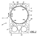
本発明の好ましい実施形態に係るシリンダヘッドガスケットの斜視図は、図1に示され、その正面図は、図2に示される。
DESCRIPTION OF PREFERRED EMBODIMENTS A perspective view of a cylinder head gasket according to a preferred embodiment of the present invention is shown in FIG. 1, and a front view thereof is shown in FIG.
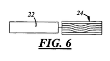
図3、4および5は各々、シリンダヘッドガスケットの主な構成要素、すなわち、キャリア部材27、機能性環状封止リング24および環状の保護層材26のうち1つをそれぞれ示す正面図である。図6〜10は各々、図2のA−A線、B−B線、C−C線、D−D線およびE−E線に沿った断面図である。
3, 4 and 5 are front views showing the main components of the cylinder head gasket, that is, one of the carrier member 27, the functional
キャリア部材22は、冷間圧延鋼材からなる単層板である。キャリア部材には、複数の開口、たとえば、ピストン部材用のシリンダ開口30、エンジンを流通する冷却液用の冷却液開口32、34、36、38および40、エンジン押し棒を移動可能にするための開口42および44、および高圧油を流通するための開口46が形成されている。
The
理解すべきことは、図面に示されたガスケット部材20の開口の形状、構造、数および機能は、例示的であることである。ガスケットは、異なるエンジンに適合するように、さまざまなサイズ、形状および開口を有することができる。周知のように、シリンダヘッドガスケットは、エンジンにおいて、エンジンブロックとエンジンマニホールドとの間に取付けられ、その役目が、上述した2つの構造の間の接合部を封止し、燃焼ガス、およびエンジン冷却液、エンジンオイルなど材料がそこから漏れないように防止することである。多くのシリンダヘッドガスケットは、たとえば、エンジン冷却液、押し棒およびエンジンオイル用の開口を含む。これらの開口は、図面に示された実施形態の開口とは異なる機能、異なる配置および異なる大きさを有してもよい。また、シリンダヘッドガスケットの代替的な実施形態は、2つまたは3つ以上のシリンダの周囲を同時に封止するのに十分なサイズおよび拡張構成を有してもよい。このような実施形態の場合、キャリア部材は、図2に示された構造と同様な一連の構造を併設して一体化することによって形成された一体化鋳型構造を有するであろう。
It should be understood that the shape, structure, number and function of the openings of the
封止リング24は、円環形状を有し、キャリア部材に嵌合されたときに、中央の円筒開口30内に配置される。封止リングは、複数の層を有する。図示の実施形態において、リング24は、「機能」層50と呼ばれる3つの層を有する。これらの3つの機能層は、好ましくはステンレス鋼材料から作られる。
The
本発明の他の実施形態において、環状の封止リングは、異なる数の層、たとえば、1つの層、2つの層、4つの層または5つの層を有してもよい。含まれる層の数は、複数の要素、たとえばエンジンの大きさおよび種類、シリンダ内燃料の燃焼により生成された圧力および熱量に依存する。 In other embodiments of the invention, the annular sealing ring may have a different number of layers, for example, one layer, two layers, four layers or five layers. The number of layers included depends on a number of factors, such as the size and type of engine, the pressure and the amount of heat generated by the combustion of in-cylinder fuel.
保護層26は、ステンレス鋼材料から作られ、封止リングの両側に配置される。
図6は、封止リング部材24および保護層26を示す断面図である。この断面は、図2のA−A線に沿って切断したものである。図示のように、封止リング24の層からなる環状体は、シリンダ開口30の内側に配置され、キャリア部材の平面と同一平面に整列されている。
The
FIG. 6 is a cross-sectional view showing the sealing
封止リング層も、その周囲に位置する複数のタブ部材60を有している。タブ部材は、開口62を有する。図3に示すように、封止リングをキャリア部材22の開口30に配置したときに、タブ部材は、キャリア部材の凹部64に嵌合する。
The sealing ring layer also has a plurality of
封止リングをキャリア部材22の開口30内に適切に配置した後、保護リング層26を封止リング部材24の両側に配置して、図2に示されたガスケット構造体20を形成する。図5に示すように、保護リング層26の各々は、その外周に複数のタブ部材70を有する。ガスケットを組立てるときに、これらのタブ部材は、キャリア部材27の凹部64内に配置され、位置決められる。
After the sealing ring is properly placed in the opening 30 of the
図7および8は、それぞれ図2のB−B線およびC−C線に沿った断面図である。図7は、凹部64においてタブ部材60および70の位置決めを示している。図7に示すように、凹部64の平面は、キャリア部材22の他の部分の平面から物理的に凹設される。これにより、保護層26のタブ部材70は、封止リングのタブ部材60の端部と重畳することができ、封止リングのタブ部材60の端部を越えて径方向の外側に延在することができる。
7 and 8 are sectional views taken along lines BB and CC in FIG. 2, respectively. FIG. 7 shows the positioning of the
図2および図7に示した方法により、3つの構成要素22、24および26を組立てた後、図2のC−C線に沿った断面図である図8に示すように、封止リング24のタブ60の開口62において、保護層26を互いにスポット溶接する。再び図2を参照して、実施例において、構成要素を互いに固定して保持するために、シリンダヘッドガスケット22は、4つのスポット溶接点100により溶接される。
After assembling the three
図示された実施形態において、5つのタブ部材60および4つのタブ部材70が設けられている。構成要素に設けられたタブ部材の数および配置が例示であり、異なる数および異なる配置のタブ部材を設けてもよい。同様に、タブ部材と対応して、異なる数および異なる配置の凹部をキャリア部材に形成してもよい。また、スポット溶接の数および配置は、タブおよび凹部の数および位置に依存する。
In the illustrated embodiment, five
エンジンブロックとマニホールドとの間の開口32、34、36、38、40、42、44および46を封止し、漏れを防止するために、好ましくは、すべての開口の上面にエラストマー封止材料を設置する。図9および10は、それぞれ図2のD−D線およびE−E線に沿った断面図である。封止部材120は、好ましくは、キャリア部材22上で各開口の周囲に成形される。
In order to seal the
図9および10に示すように、封止部材120は、封止材料からビーズ形に形成される。これらの封止部材は、開口の内側縁部に配置され、キャリア部材22の両側から横方向外側に突出するとともに、開口の径方向内側に延在している。図9および10に示された封止部材120は、すべての開口32、34、36、38、40、42、44および46の周囲に配置された封止部材の代表的例である。
As shown in FIGS. 9 and 10, the sealing
エンジンブロックおよびマニホールドを組立てるときに、封止部材120は、開口の周囲に緊密かつ安全な封止を提供する。
When assembling the engine block and manifold, the sealing
本発明は、好ましい実施形態を参照して説明したが、これらの実施形態に限定されないことを理解すべきである。実施形態に対する任意の変更および修正は、すべて添付の特許請求の範囲によって定義される本発明の範囲内に含まれる。 Although the present invention has been described with reference to preferred embodiments, it should be understood that the invention is not limited to these embodiments. All changes and modifications to the embodiments are included within the scope of the invention as defined by the appended claims.
Claims (9)
単層のキャリア部材を備え、前記キャリア部材は、シリンダ開口および複数の他の開口を有し、
シリンダ開口に配置された環状の封止リングを備え、前記封止リングは、複数の環状の機能層および1対の環状の保護層を含み、前記保護層の1つは、前記封止リングの一方側に配置され、
前記機能層に位置する複数の第1タブ部材と、前記保護層に位置する複数の第2タブ部材とをさらに備え、
前記第1タブ部材は内部に開口を有し、前記第1および第2タブ部材は、前記開口を介して互いにスポット溶接されている、シリンダヘッドガスケット。 A cylinder head gasket,
Comprising a single layer carrier member, the carrier member having a cylinder opening and a plurality of other openings;
An annular sealing ring disposed in a cylinder opening, the sealing ring including a plurality of annular functional layers and a pair of annular protective layers, wherein one of the protective layers is formed on the sealing ring. Placed on one side ,
A plurality of first tab members located in the functional layer; and a plurality of second tab members located in the protective layer;
The cylinder head gasket, wherein the first tab member has an opening therein, and the first and second tab members are spot welded to each other through the opening .
前記第1タブ部材と第2タブ部材とは、前記凹部部材に配置されている、請求項1に記載のシリンダヘッドガスケット。 The cylinder head gasket is provided on the carrier member further comprises a plurality of recesses member disposed around the cylinder opening,
The cylinder head gasket according to claim 1, wherein the first tab member and the second tab member are disposed in the recess member.
Applications Claiming Priority (3)
| Application Number | Priority Date | Filing Date | Title |
|---|---|---|---|
| US13/828,024 US8960682B2 (en) | 2013-03-14 | 2013-03-14 | Hybrid ring welded cylinder head gasket |
| US13/828,024 | 2013-03-14 | ||
| PCT/US2014/019715 WO2014158735A1 (en) | 2013-03-14 | 2014-03-01 | Hybrid ring welded cylinder head gasket |
Publications (3)
| Publication Number | Publication Date |
|---|---|
| JP2016512310A JP2016512310A (en) | 2016-04-25 |
| JP2016512310A5 JP2016512310A5 (en) | 2017-03-09 |
| JP6450910B2 true JP6450910B2 (en) | 2019-01-16 |
Family
ID=50336539
Family Applications (1)
| Application Number | Title | Priority Date | Filing Date |
|---|---|---|---|
| JP2016500529A Expired - Fee Related JP6450910B2 (en) | 2013-03-14 | 2014-03-01 | Cylinder head gasket with welded hybrid ring |
Country Status (6)
| Country | Link |
|---|---|
| US (1) | US8960682B2 (en) |
| EP (1) | EP2971876B1 (en) |
| JP (1) | JP6450910B2 (en) |
| KR (1) | KR20150130518A (en) |
| CN (1) | CN105190130B (en) |
| WO (1) | WO2014158735A1 (en) |
Families Citing this family (3)
| Publication number | Priority date | Publication date | Assignee | Title |
|---|---|---|---|---|
| JP5723846B2 (en) * | 2012-10-04 | 2015-05-27 | 内山工業株式会社 | gasket |
| USD747445S1 (en) * | 2014-02-10 | 2016-01-12 | Evoqua Water Technologies Llc | One piece gasket assembly |
| DE202019104931U1 (en) * | 2019-09-06 | 2020-12-08 | Reinz-Dichtungs-Gmbh | Cylinder head gasket with a carrier layer and at least one insert sealing element |
Family Cites Families (28)
| Publication number | Priority date | Publication date | Assignee | Title |
|---|---|---|---|---|
| DE8102660U1 (en) * | 1981-07-09 | Elring Dichtungswerke Gmbh, 7012 Fellbach | Flat gasket, in particular cylinder head gasket for internal combustion engines | |
| US1782870A (en) | 1928-09-10 | 1930-11-25 | James G Dickson | Gasket |
| US2034610A (en) | 1934-01-22 | 1936-03-17 | Dickson Gasket Company | Gasket |
| DE1248397B (en) | 1966-06-15 | 1967-08-24 | Goetzewerke | Flange seal |
| FR1592635A (en) | 1967-11-21 | 1970-05-19 | ||
| GB1305366A (en) | 1971-05-28 | 1973-01-31 | ||
| JPS51144646U (en) * | 1975-05-16 | 1976-11-20 | ||
| FR2446970A1 (en) * | 1979-01-18 | 1980-08-14 | Renault Vehicules Ind | IMPROVED CYLINDER HEAD GASKET FOR INTERNAL COMBUSTION ENGINES |
| JPS5851041U (en) * | 1981-10-01 | 1983-04-06 | 鎌苅 良太 | metal gasket |
| US4518168A (en) | 1984-03-02 | 1985-05-21 | Dana Corporation | Multi-thickness fire ring assembly |
| IT1186800B (en) | 1985-06-03 | 1987-12-16 | Tako Spa | GASKET FOR CYLINDER HEAD OF INTERNAL COMBUSTION ENGINE FREE OF ASBESTOS |
| US4645217A (en) * | 1985-11-29 | 1987-02-24 | United Technologies Corporation | Finger seal assembly |
| DE3903918A1 (en) * | 1989-02-10 | 1990-08-16 | Goetze Ag | Flat gasket, particularly a cylinder head gasket for internal combustion engines |
| US5338046A (en) | 1992-12-18 | 1994-08-16 | Dana Corporation | Composite powdered metal retaining ring |
| US5505466A (en) | 1992-12-18 | 1996-04-09 | Dana Corporation | Cylinder head gasket with retaining ring and spring seal |
| US5890719A (en) | 1996-08-27 | 1999-04-06 | Parker-Hannifin Corporation | Combination metal and elastomer cylinder head gasket |
| DE19654283A1 (en) * | 1996-12-24 | 1998-06-25 | Reinz Dichtungs Gmbh | Metallic flat gasket |
| US5921558A (en) | 1997-04-15 | 1999-07-13 | Dana Corporation | High recovery combustion seal gasket |
| US6241253B1 (en) | 1998-06-08 | 2001-06-05 | Interface Solutions, Inc. | Edge coated soft gasket |
| US6093467A (en) | 1997-08-29 | 2000-07-25 | Interface Solutions, Inc. | High sealing gaskets |
| JP3792934B2 (en) * | 1999-05-12 | 2006-07-05 | 内山工業株式会社 | Gasket and manufacturing method thereof |
| FR2827638B1 (en) * | 2001-07-23 | 2003-09-19 | Meillor Sa | CYLINDER HEAD GASKET COMPRISING AN EDGE-TO-EDGE STOPPER |
| WO2005012769A2 (en) * | 2003-07-28 | 2005-02-10 | Coltec Industries, Inc. | Head gasket assembly |
| CA2477342A1 (en) * | 2003-08-28 | 2005-02-28 | Freudenberg-Nok General Partnership | Improved sealing gasket with flexible stopper |
| US7726662B2 (en) * | 2006-07-10 | 2010-06-01 | Dana Automotive Systems Group, Llc | Stopped-active type cylinder head gasket |
| ATE546674T1 (en) | 2008-06-21 | 2012-03-15 | Federal Mogul Sealing Sys Spa | FLAT SEAL |
| CN102483161B (en) | 2009-08-19 | 2014-11-05 | 费德罗-莫格尔公司 | Cylinder head gasket assembly |
| JP5425954B2 (en) | 2012-03-14 | 2014-02-26 | 石川ガスケット株式会社 | Rubber ring for gasket |
-
2013
- 2013-03-14 US US13/828,024 patent/US8960682B2/en not_active Expired - Fee Related
-
2014
- 2014-03-01 EP EP14711381.5A patent/EP2971876B1/en active Active
- 2014-03-01 KR KR1020157029228A patent/KR20150130518A/en not_active Application Discontinuation
- 2014-03-01 JP JP2016500529A patent/JP6450910B2/en not_active Expired - Fee Related
- 2014-03-01 WO PCT/US2014/019715 patent/WO2014158735A1/en active Application Filing
- 2014-03-01 CN CN201480025251.3A patent/CN105190130B/en not_active Expired - Fee Related
Also Published As
| Publication number | Publication date |
|---|---|
| US20140265153A1 (en) | 2014-09-18 |
| US8960682B2 (en) | 2015-02-24 |
| WO2014158735A1 (en) | 2014-10-02 |
| KR20150130518A (en) | 2015-11-23 |
| JP2016512310A (en) | 2016-04-25 |
| CN105190130A (en) | 2015-12-23 |
| EP2971876B1 (en) | 2019-07-31 |
| CN105190130B (en) | 2017-08-08 |
| EP2971876A1 (en) | 2016-01-20 |
Similar Documents
| Publication | Publication Date | Title |
|---|---|---|
| JP2019505742A (en) | Crankcase assembly for reciprocating machines | |
| JP6246797B2 (en) | Metal gasket | |
| KR20130008027A (en) | Multilayer gasket with labyrinth stopper | |
| JP2018200104A (en) | Small-size elastic sealing feature of inner part of main combustion sealing die pushing | |
| JP6450910B2 (en) | Cylinder head gasket with welded hybrid ring | |
| EP3315830B1 (en) | Reciprocating cylinder liner seal assembly | |
| US9732698B2 (en) | Temperature reducing channel | |
| JP5136808B2 (en) | Cylinder head gasket and manufacturing method thereof | |
| JP2017519166A (en) | Cylinder head gasket with compression limiter and full bead load | |
| US10082103B2 (en) | Method of making engine spacer plate gasket | |
| CN104763529A (en) | Boot seal for variable compression ratio engine | |
| US20160252046A1 (en) | Cylinder Head Gasket | |
| KR20150127629A (en) | Multi-layer gasket | |
| US10634251B2 (en) | Multi-layer gasket assembly | |
| JP2005155713A (en) | Metallic gasket | |
| GB2532971A (en) | Cylinder head gasket | |
| US20170191445A1 (en) | Multi-Layer Gasket Assembly | |
| CN211008808U (en) | Oil pan sealing gasket with limiting sleeve structure | |
| US10119494B2 (en) | Multi-layer gasket assembly | |
| KR20110003044A (en) | Cylinder head gasket | |
| JPH072672U (en) | Metal laminated cylinder head gasket | |
| CN104265896A (en) | Sealed exhaust tube connector pad | |
| TWM468569U (en) | Improvement of cylinder gasket |
Legal Events
| Date | Code | Title | Description |
|---|---|---|---|
| A521 | Request for written amendment filed |
Free format text: JAPANESE INTERMEDIATE CODE: A523 Effective date: 20170202 |
|
| A621 | Written request for application examination |
Free format text: JAPANESE INTERMEDIATE CODE: A621 Effective date: 20170202 |
|
| A977 | Report on retrieval |
Free format text: JAPANESE INTERMEDIATE CODE: A971007 Effective date: 20171214 |
|
| A131 | Notification of reasons for refusal |
Free format text: JAPANESE INTERMEDIATE CODE: A131 Effective date: 20180116 |
|
| A521 | Request for written amendment filed |
Free format text: JAPANESE INTERMEDIATE CODE: A523 Effective date: 20180413 |
|
| TRDD | Decision of grant or rejection written | ||
| A01 | Written decision to grant a patent or to grant a registration (utility model) |
Free format text: JAPANESE INTERMEDIATE CODE: A01 Effective date: 20181002 |
|
| A711 | Notification of change in applicant |
Free format text: JAPANESE INTERMEDIATE CODE: A712 Effective date: 20181031 |
|
| A61 | First payment of annual fees (during grant procedure) |
Free format text: JAPANESE INTERMEDIATE CODE: A61 Effective date: 20181101 |
|
| R150 | Certificate of patent or registration of utility model |
Ref document number: 6450910 Country of ref document: JP Free format text: JAPANESE INTERMEDIATE CODE: R150 |
|
| LAPS | Cancellation because of no payment of annual fees |