以下、複数の実施形態による冷蔵庫を、図面を参照して説明する。なお、各実施形態において実質的に同一の構成部位には同一の符号を付し、説明を省略する。
(第1実施形態)
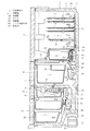
まず、第1実施形態について、図1〜図9を参照して説明する。図1および図2に示すように、冷蔵庫本体1は、前面が開口した縦長矩形箱状の断熱箱体2内に、複数の貯蔵室を設けて構成されている。具体的には、断熱箱体2内には、上段から順に、冷蔵室3、野菜室4が設けられ、その下方に製氷室5と小冷凍室6が左右に並べて設けられ、これらの下方に冷凍室7が設けられている。製氷室5内には、周知の自動製氷装置8(図1参照)が設けられている。なお、断熱箱体2は、基本的には、鋼板製の外箱2aと合成樹脂製の内箱2bとの間に断熱材2cを設けて構成されている。
Hereinafter, refrigerators according to a plurality of embodiments will be described with reference to the drawings. In addition, in each embodiment, the same code | symbol is attached | subjected to the substantially same component and description is abbreviate | omitted.
(First embodiment)
First, a first embodiment will be described with reference to FIGS. As shown in FIG. 1 and FIG. 2, the refrigerator main body 1 is configured by providing a plurality of storage rooms in a heat insulating box 2 having a vertically long rectangular box shape whose front surface is open. Specifically, in the heat insulation box 2, a refrigeration room 3 and a vegetable room 4 are provided in order from the top, and an ice making room 5 and a small freezer room 6 are provided side by side below, and below these. A freezer compartment 7 is provided. A known automatic ice making device 8 (see FIG. 1) is provided in the ice making chamber 5. The heat insulating box 2 is basically configured by providing a heat insulating material 2c between an outer box 2a made of steel plate and an inner box 2b made of synthetic resin.
前記冷蔵室3及び野菜室4は、いずれも冷蔵温度帯(例えば1〜5℃)の貯蔵室であり、それらの間は、プラスチック製の仕切板10により上下に仕切られている。なお、冷蔵室3の温度は約4℃、野菜室4の温度はそれよりやや高い約5℃が好ましいとされている。前記冷蔵室3の前面部には、ヒンジ開閉式の断熱扉3aが設けられ、前記野菜室4の前面には引出し式の断熱扉4aが設けられている。この断熱扉4aの背面部には、貯蔵容器を構成する下部ケース11が連結されている。下部ケース11の上部には、下部ケース11よりも小型の上部ケース12が設けられている。
Each of the refrigerator compartment 3 and the vegetable compartment 4 is a storage compartment in a refrigeration temperature zone (for example, 1 to 5 ° C.), and is partitioned vertically by a plastic partition plate 10. The temperature of the refrigerator compartment 3 is preferably about 4 ° C., and the temperature of the vegetable compartment 4 is preferably about 5 ° C., which is slightly higher. A hinged heat insulating door 3 a is provided on the front surface of the refrigerator compartment 3, and a drawer heat insulating door 4 a is provided on the front surface of the vegetable room 4. The lower case 11 which comprises a storage container is connected with the back surface part of this heat insulation door 4a. An upper case 12 smaller than the lower case 11 is provided on the upper portion of the lower case 11.
前記冷蔵室3内は、複数の棚板13により上下に複数段に区切られている。図3に示すように、冷蔵室3内の最下部(前記仕切板10の上部)において、右側にはチルド室14が設けられ、その左側には卵ケース15と小物ケース16が上下に設けられ、さらに、これらの左側には貯水タンク17が設けられている。チルド室14には、チルドケース18が出し入れ可能に設けられている。チルド室14も貯蔵室を構成する。チルド室14の温度は、0℃ぐらいが好ましいとされている。貯水タンク17は、前記自動製氷装置8の製氷皿8aに供給する水を貯留するためのものである。
The inside of the refrigerator compartment 3 is divided into a plurality of stages by a plurality of shelf boards 13. As shown in FIG. 3, a chilled chamber 14 is provided on the right side at the bottom of the refrigerator compartment 3 (upper part of the partition plate 10), and an egg case 15 and an accessory case 16 are provided vertically on the left side thereof. Furthermore, a water storage tank 17 is provided on the left side of these. A chilled case 18 is provided in the chilled chamber 14 so that it can be taken in and out. The chilled chamber 14 also constitutes a storage chamber. The temperature of the chilled chamber 14 is preferably about 0 ° C. The water storage tank 17 is for storing water to be supplied to the ice tray 8 a of the automatic ice making device 8.
前記製氷室5、小冷凍室6、並びに冷凍室7は、いずれも冷凍温度帯(例えば−10〜−20℃)の貯蔵室であり、前記野菜室4と製氷室5および小冷凍室6との間は、断熱仕切壁19により上下に仕切られている。製氷室5の前面部には、引出し式の断熱扉5aが設けられており、その断熱扉5aの背面部に貯氷容器20が連結されている。小冷凍室6の前面部にも、図示はしないが貯蔵容器が連結された引出し式の断熱扉が設けられている。冷凍室7の前面部にも、貯蔵容器22が連結された引出し式の断熱扉7aが設けられている。
The ice making room 5, the small freezing room 6, and the freezing room 7 are all storage rooms in a freezing temperature zone (for example, −10 to −20 ° C.), and the vegetable room 4, the ice making room 5, and the small freezing room 6 The space is partitioned vertically by a heat insulating partition wall 19. A drawer-type heat insulating door 5a is provided on the front surface of the ice making chamber 5, and an ice storage container 20 is connected to the back surface of the heat insulating door 5a. Although not shown, a drawer-type heat insulating door connected to a storage container is also provided on the front surface of the small freezer compartment 6. A drawer-type heat insulating door 7 a to which a storage container 22 is connected is also provided on the front surface of the freezer compartment 7.
この冷蔵庫本体1内には、全体として詳しく図示はしないが、前記冷蔵室3及び野菜室4を冷却するための冷蔵用冷却器24(冷却器)と、前記製氷室5、小冷凍室6、冷凍室7を冷却するための冷凍用冷却器25との2つの冷却器を備える冷凍サイクルが組込まれる。冷蔵庫本体1の下端部背面側には、機械室26が設けられ、詳しく図示はしないが、この機械室26内に、冷凍サイクルを構成する圧縮機27及び凝縮器などが配設されていると共に、それらを冷却するための冷却ファンや除霜水蒸発皿28等が配設されている。冷蔵庫本体1の背面下部寄り部分には、全体を制御するマイコン等を実装した制御装置29が設けられている。
Although not shown in detail in the refrigerator main body 1 as a whole, the refrigerator 24 (cooler) for cooling the refrigerator compartment 3 and the vegetable compartment 4, the ice making chamber 5, the small freezer compartment 6, A refrigeration cycle comprising two coolers, a refrigeration cooler 25 for cooling the freezer compartment 7, is incorporated. A machine room 26 is provided on the rear side of the lower end of the refrigerator body 1, and although not shown in detail, a compressor 27 and a condenser that constitute a refrigeration cycle are disposed in the machine room 26. A cooling fan, a defrosted water evaporating dish 28, and the like are provided for cooling them. A control device 29 in which a microcomputer or the like for controlling the whole is mounted is provided near the lower rear portion of the refrigerator body 1.
冷蔵庫本体1内の前記冷凍室7の背部には、冷凍用冷却器室30が設けられている。この冷凍用冷却器室30内に、下部に位置させて前記冷凍用冷却器25や除霜用ヒータ(図示せず)等が配設されていると共に、上部に位置させて冷凍用送風機31が配設されている。冷凍用冷却器室30の前面の中間部には、冷気吹出口30aが設けられ、下端部には、戻り口30bが設けられている。
A refrigeration cooler chamber 30 is provided behind the freezing chamber 7 in the refrigerator body 1. In the refrigeration cooler chamber 30, the refrigeration cooler 25, a defrosting heater (not shown) and the like are disposed at the lower portion, and the refrigeration blower 31 is disposed at the upper portion. It is arranged. A cold air outlet 30a is provided in the middle portion of the front surface of the refrigeration cooler chamber 30, and a return port 30b is provided in the lower end portion.
この構成において、冷凍用送風機31が駆動されると、冷凍用冷却器25により生成された冷気が、前記冷気吹出口30aから製氷室5、小冷凍室6、冷凍室7内に供給された後、前記戻り口30bから冷凍用冷却器室30内に戻されるといった循環を行うようになっている。これにより、それら製氷室5、小冷凍室6、および冷凍室7が冷却される。尚、冷凍用冷却器25の下方部には、当該冷凍用冷却器25の除霜時の除霜水を受ける排水樋32が設けられている。その排水樋32に受けられた除霜水は、庫外の前記機械室26内に設けられた除霜水蒸発皿28に導かれ、蒸発するようになっている。
In this configuration, after the refrigeration blower 31 is driven, the cold air generated by the refrigeration cooler 25 is supplied from the cold air outlet 30a into the ice making chamber 5, the small freezer compartment 6, and the freezer compartment 7. The circulation is performed such that the refrigerant is returned from the return port 30b into the refrigeration cooler chamber 30. Thereby, the ice making room 5, the small freezer room 6, and the freezer room 7 are cooled. A drainage basin 32 that receives defrost water when the refrigeration cooler 25 is defrosted is provided below the refrigeration cooler 25. The defrost water received by the drainage basin 32 is guided to the defrost water evaporating tray 28 provided in the machine chamber 26 outside the warehouse, and evaporates.
そして、冷蔵庫本体1内における前記冷蔵室3および野菜室4の背部には、前記冷蔵用冷却器24や、この冷蔵用冷却器24により生成された冷気を前記冷蔵室3(及び野菜室4)内に供給するための冷気ダクト34(ダクト)、前記冷気を循環させるための冷蔵用送風機35(送風機)等が、以下のようにして配設される。即ち、冷蔵庫本体1における冷蔵室3の最下段の後方(前記チルド室14の後方)には、冷気ダクト34の一部を構成する冷蔵用冷却器室36が設けられ、この冷蔵用冷却器室36内に冷蔵用冷却器24が配設されている。
And in the back part of the said refrigerator compartment 3 and the vegetable compartment 4 in the refrigerator main body 1, the said cooler 24 and the cool air produced | generated by this refrigerator for refrigerator 24 are the said refrigerator compartment 3 (and vegetable compartment 4). A cold air duct 34 (duct) for supplying the air inside, a refrigeration blower 35 (blower) for circulating the cold air, and the like are arranged as follows. That is, a refrigeration cooler chamber 36 that constitutes a part of the cold air duct 34 is provided behind the lowermost stage of the refrigeration chamber 3 in the refrigerator main body 1 (behind the chilled chamber 14). A refrigerating cooler 24 is disposed in the inside 36.
冷蔵用冷却器室36の上方には、上方に延びる冷気供給ダクト37が設けられていて、冷蔵用冷却器室36の上端部が冷気供給ダクト37の下端部に連通している。この場合、冷蔵用冷却器室36と冷気供給ダクト37により、冷気ダクト34を構成している。冷蔵用冷却器室36の前部壁36aは、冷気供給ダクト37よりも前方へ膨出している。なお、前部壁36aの下方には、図6〜図8に示すように、当該前部壁36aよりも前方へ膨出した下部膨出部36cが設けられていて、上部の前部壁36aと下部の下部膨出部36cとの間に段部36bが形成されている。前部壁36aの裏側には、断熱性を有する断熱材38が設けられている。冷気供給ダクト37の前部には、冷蔵室3内に開口する冷気供給口39が複数個設けられている。
A cold air supply duct 37 extending upward is provided above the refrigerating cooler chamber 36, and the upper end portion of the refrigerating cooler chamber 36 communicates with the lower end portion of the cold air supply duct 37. In this case, the cold air duct 34 is constituted by the refrigeration cooler chamber 36 and the cold air supply duct 37. The front wall 36 a of the refrigeration cooler chamber 36 bulges forward from the cold air supply duct 37. As shown in FIGS. 6 to 8, a lower bulging portion 36c bulging forward from the front wall 36a is provided below the front wall 36a, and the upper front wall 36a. A step portion 36b is formed between the lower bulging portion 36c and the lower portion. A heat insulating material 38 having heat insulating properties is provided on the back side of the front wall 36a. In front of the cold air supply duct 37, a plurality of cold air supply ports 39 that open into the refrigerator compartment 3 are provided.
冷蔵用冷却器室36内の下部には、冷蔵用冷却器24の下方に位置させて、該冷蔵用冷却器24からの除霜水を受ける排水樋40が設けられている。この排水樋40に受けられた除霜水も、前記排水樋32で受けられた除霜水と同様に、庫外の前記機械室26内に設けられた除霜水蒸発皿28に導かれ、蒸発するようになっている。排水樋40の左右の長さ寸法および前後の奥行き寸法は、冷蔵用冷却器24の左右の長さ寸法および前後の奥行き寸法よりも大きく設定されていて、冷蔵用冷却器24から滴下する除霜水をすべて受けられる大きさに構成されている。
A drainage basin 40 for receiving defrost water from the refrigeration cooler 24 is provided below the refrigeration cooler 24 in the lower part of the refrigeration cooler chamber 36. The defrosted water received by the drainage basin 40 is also led to the defrosting water evaporating dish 28 provided in the machine room 26 outside the cabinet, similarly to the defrosting water received by the drainage basin 32, It is supposed to evaporate. The left and right length dimensions and the front and rear depth dimensions of the drainage basin 40 are set larger than the left and right length dimensions and the front and rear depth dimensions of the refrigeration cooler 24, and defrosting dripping from the refrigeration cooler 24. It is configured to receive all water.
前記野菜室4の後方には、排水樋40の下方に位置させて、前記冷蔵用送風機35が配設されていると共に、送風ダクト42及び吸込み口43が設けられている。そのうち送風ダクト42は、上端部が排水樋40をう回するようにして冷蔵用冷却器室36(冷気ダクト34)に連通している。吸込み口43は、野菜室4において開口している。なお、冷蔵室3の底部を構成する仕切板10の後部の左右の両隅部には、図5に示すように、連通口44が形成されている(図5には右側の連通口44のみ示す)。この連通口44は、冷蔵室3とこれの下方の野菜室4とを連通させている。
Behind the vegetable compartment 4, the refrigeration blower 35 is disposed below the drainage basin 40, and a blow duct 42 and a suction port 43 are provided. Among them, the air duct 42 communicates with the refrigeration cooler chamber 36 (cold air duct 34) so that the upper end of the air duct 42 circulates the drainage basin 40. The suction port 43 is open in the vegetable compartment 4. As shown in FIG. 5, communication ports 44 are formed at both the left and right corners of the rear portion of the partition plate 10 constituting the bottom of the refrigerator compartment 3 (only the right communication port 44 is shown in FIG. 5). Show). The communication port 44 allows the refrigerator compartment 3 to communicate with the vegetable compartment 4 below it.
この構成において、冷蔵用送風機35が駆動されると、主に図1の白抜き矢印で示すように、野菜室4内の空気が吸込み口43から冷蔵用送風機35側に吸い込まれ、その吸い込まれた空気は、送風ダクト42側へ吹き出される。送風ダクト42側へ吹き出された空気は、冷気ダクト34(冷蔵用冷却器室36および冷気供給ダクト37)を通り、複数の冷気供給口39から冷蔵室3内に吹き出される。冷蔵室3内に吹き出された空気は、連通口44を通して野菜室4内にも供給され、最終的に冷蔵用送風機35に吸い込まれるという循環が行われる。この過程で、冷蔵用冷却器室36内を通る空気が冷蔵用冷却器24に接触し冷却されて冷気となり、その冷気が冷蔵室3および野菜室4に供給されることによって、冷蔵室3および野菜室4が冷蔵温度帯の温度に冷却される。
In this configuration, when the refrigeration blower 35 is driven, the air in the vegetable compartment 4 is sucked into the refrigeration blower 35 side from the suction port 43 mainly as indicated by the white arrow in FIG. The air is blown out to the air duct 42 side. The air blown out to the air duct 42 side passes through the cold air duct 34 (the refrigeration cooler chamber 36 and the cold air supply duct 37) and is blown out into the refrigerating chamber 3 from the plurality of cold air supply ports 39. The air blown into the refrigerator compartment 3 is also supplied into the vegetable compartment 4 through the communication port 44 and finally circulated by being sucked into the refrigerator fan 35 for refrigerator. In this process, the air passing through the refrigeration cooler chamber 36 comes into contact with the refrigeration cooler 24 and is cooled to become cold air, and the cold air is supplied to the refrigeration chamber 3 and the vegetable compartment 4. The vegetable compartment 4 is cooled to a temperature in the refrigeration temperature zone.
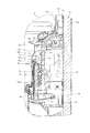
前記冷気ダクト34のうち冷蔵用冷却器室36の前面側には、図2、図4に示すように、前方から見て右側で、前記チルド室14の後方に位置させて、ミスト用専用ダクト45が着脱可能に設けられている。このミスト用専用ダクト45は、図5〜図8にも示すように、冷蔵用冷却器室36の前部壁36aと、冷蔵用冷却器室36の前面に装着されたダクト構成部材46によって形成されていて、ミスト用専用ダクト45を形成するダクト構成部材46が前部壁36aに対して着脱可能な構成となっている。この場合、ミスト用専用ダクト45は、前部壁36aに沿って左右方向に長く、かつ前後方向の奥行き寸法が小さく、扁平な矩形箱状に形成されている。そして、このミスト用専用ダクト45内に、ミストを放出するためのミスト放出手段を構成する静電霧化装置48の主体部が収容されている。以下、この静電霧化装置48について詳述する。
As shown in FIGS. 2 and 4, the cold air duct 34 is located on the front side of the refrigeration cooler chamber 36 on the right side when viewed from the front and behind the chilled chamber 14, and is a dedicated duct for mist. 45 is detachably provided. As shown in FIGS. 5 to 8, the mist exclusive duct 45 is formed by a front wall 36 a of the refrigeration cooler chamber 36 and a duct component member 46 attached to the front surface of the refrigeration cooler chamber 36. In addition, the duct component member 46 forming the mist dedicated duct 45 is detachable from the front wall 36a. In this case, the mist exclusive duct 45 is formed in a flat rectangular box shape that is long in the left-right direction along the front wall 36a and has a small depth dimension in the front-rear direction. And the main part of the electrostatic atomizer 48 which comprises the mist discharge | release means for discharging | emitting mist is accommodated in this duct 45 for mist. Hereinafter, the electrostatic atomizer 48 will be described in detail.
静電霧化装置48は、図9に示すように、ミスト放出部50を有するミスト発生ユニット51と、前記ミスト放出部50に負の高電圧を印加するための電源装置(トランス)52とを備えて構成されている。ミスト発生ユニット51は、ミスト放出部50に水分を供給する給水部53を備えている。給水部53は、左右方向に延びる水平部53aと、この水平部53aの右端部から下方に延びる垂直部53bとを有し、正面から見て逆L字状をなしていて、L字状をなすケース54内に、保水材55を収容して構成されている。したがって、給水部53は、水平部53aと垂直部53bとの間に屈折部53cを有している。給水部53における水平部53aと垂直部53bは、冷気ダクト34における冷蔵用冷却器室36の前部壁36aに平行となるように当該前部壁36aに沿って配置されている。
As shown in FIG. 9, the electrostatic atomizer 48 includes a mist generating unit 51 having a mist emitting unit 50 and a power supply device (transformer) 52 for applying a negative high voltage to the mist emitting unit 50. It is prepared for. The mist generating unit 51 includes a water supply unit 53 that supplies moisture to the mist discharge unit 50. The water supply portion 53 has a horizontal portion 53a extending in the left-right direction and a vertical portion 53b extending downward from the right end portion of the horizontal portion 53a. The water supply portion 53 has an inverted L shape as viewed from the front, and has an L shape. A water retaining material 55 is accommodated in the case 54 formed. Therefore, the water supply part 53 has the refracting part 53c between the horizontal part 53a and the vertical part 53b. The horizontal part 53 a and the vertical part 53 b in the water supply part 53 are arranged along the front wall 36 a so as to be parallel to the front wall 36 a of the refrigeration cooler chamber 36 in the cold air duct 34.
保水材55は、例えば繊維を絡ませたフェルト状のもので、吸水性および保水性に優れていて、後述する貯水容器56に貯留された水(除霜水)を毛細管現象により吸い上げる。なお、保水材55は、水を毛細管現象で吸い上げることができれば、連続発泡体のものでもよい。給水部53の水平部53aは、ミスト用専用ダクト45内のやや右寄りに配置され、垂直部53bの下端部は、図8に示すように、ダクト構成部材46の下部、前記冷蔵用冷却器室36の前部の段部36bに形成された孔を貫通して冷蔵用冷却器室36内の下部の前部に挿入されている。保水材55の外周はケース54により覆われている。保水材55において、水平部53aの部分と垂直部53bとの部分とを別々の部材で構成してもよい。保水材55は、貯水容器56からミスト放出部50まで水を移送する給水部材を構成する。
The water retaining material 55 is, for example, a felt-like material in which fibers are entangled, and is excellent in water absorption and water retention, and sucks up water (defrosted water) stored in a water storage container 56 described later by a capillary phenomenon. The water retaining material 55 may be a continuous foam as long as water can be sucked up by capillary action. The horizontal portion 53a of the water supply portion 53 is arranged slightly to the right in the mist dedicated duct 45, and the lower end portion of the vertical portion 53b is the lower portion of the duct component member 46, as shown in FIG. A hole formed in the front step portion 36 b of 36 is inserted into the lower front portion in the refrigerator compartment 36 for refrigeration. The outer periphery of the water retaining material 55 is covered with a case 54. In the water retaining material 55, the horizontal portion 53a and the vertical portion 53b may be formed of separate members. The water retaining material 55 constitutes a water supply member that transfers water from the water storage container 56 to the mist discharge unit 50.
冷蔵用冷却器室36内の下部の前部には、貯水部を構成する貯水容器56(図8参照)が設けられている。この貯水容器56は、冷蔵用冷却器24とこれの下方に存する前記排水樋40との間で、かつ前記給水部53の下方に位置させて、前部を冷蔵用冷却器室36の下部膨出部36cに取り付けることによって、後方へ突出するような片持ち状態に設けられている。この場合、貯水容器56の前部を取り付けた下部膨出部36cは、前部壁36aの下方にあって当該前部壁36aよりも前方へ膨出(突出)している。前部壁36aを第1の膨出部とすると、下部膨出部36cはこれよりも前方へ突出した第2の膨出部となっている。貯水容器56は、下部膨出部36cへの取り付け状態で、冷蔵用冷却器24、および冷蔵用冷却器室36の後面を形成する内箱2bから離間している。冷蔵用冷却器24は、冷蔵用冷却器室36の後面を形成する内箱2bに接触している。
A water storage container 56 (see FIG. 8) that constitutes a water storage section is provided in the front part of the lower part in the refrigerator room 36 for refrigeration. The water storage container 56 is positioned between the refrigeration cooler 24 and the drainage basin 40 below the refrigeration cooler 24 and below the water supply part 53, and the front part is a lower expansion of the refrigeration cooler chamber 36. By being attached to the protruding portion 36c, it is provided in a cantilever state so as to protrude rearward. In this case, the lower bulging portion 36c to which the front portion of the water storage container 56 is attached is below the front wall 36a and bulges (projects) forward from the front wall 36a. When the front wall 36a is the first bulging portion, the lower bulging portion 36c is a second bulging portion that protrudes forward. The water storage container 56 is separated from the refrigerating cooler 24 and the inner box 2b forming the rear surface of the refrigerating cooler chamber 36 in a state of being attached to the lower bulging portion 36c. The refrigeration cooler 24 is in contact with the inner box 2 b that forms the rear surface of the refrigeration cooler chamber 36.
前記給水部53における垂直部53bの下端部は、ダクト構成部材46の下部、前記冷蔵用冷却器室36の前部の段部36bに形成された孔を貫通して、貯水容器56内に上方から挿入されている。貯水容器56は、冷蔵用冷却器24から滴下する除霜水を受けて貯留する。給水部53の保水材55は、前述したように貯水容器56に貯留された水(除霜水)を毛細管現象により吸い上げて前記ミスト放出部50に供給する。
A lower end portion of the vertical portion 53 b in the water supply portion 53 passes through a hole formed in a lower portion of the duct component member 46 and a step portion 36 b in the front portion of the refrigeration cooler chamber 36, and extends upward into the water storage container 56. Has been inserted from. The water storage container 56 receives and stores defrost water dripped from the refrigeration cooler 24. As described above, the water retaining material 55 of the water supply unit 53 sucks up the water (defrosted water) stored in the water storage container 56 by capillary action and supplies it to the mist discharge unit 50.
貯水容器56の後部側の先端部の上部には、他よりも低く設定された溢水部56aが形成されていて、貯水容器56内に貯留された水が溢れる場合には、その溢水部56aから溢れることになる。その溢水部56aは、前記排水樋40の上方に位置していて、その溢水部56aから溢れた水は排水樋40にて受けられ、機外の除霜水蒸発皿28へ排出されるようになる。
An overflow portion 56a that is set lower than the others is formed at the upper portion of the rear end portion of the water storage container 56. When the water stored in the water storage vessel 56 overflows, the overflow portion 56a It will overflow. The overflow portion 56a is located above the drainage basin 40 so that the water overflowing from the overflow portion 56a is received by the drainage basin 40 and discharged to the defrosted water evaporating dish 28 outside the apparatus. Become.
給水部53における水平部53aに、ミスト放出部50が設けられている。ミスト放出部50は、それぞれ突部を構成する複数本のミスト放出ピン57によって構成されている。ミスト放出ピン57は、水平部53aの上部側に上向きに、複数本この場合4本が左右方向の横一列状に並び、かつそれぞれ離間して配置されているとともに、水平部53aの下部側に下向きに、複数本この場合4本が左右方向の横一列状に並び、かつそれぞれ離間して配置されている。したがって、ミスト放出部50は、異なる方向(上方と下方)に向けて突出する複数のミスト放出ピン(突部)57により構成されている。また、ミスト放出部50は、複数のミスト放出ピン(突部)57が、給水部53における水平部53aを間にして上下の反対方向に延びるように配置されている。また、複数のミスト放出ピン(突部)57は、上下2段に配置されている。各ミスト放出ピン57は、前記冷気ダクト34における冷蔵用冷却器室36の前部壁36aに平行となるように沿って配置されている。ミスト放出部50は、冷蔵室3の下方後部であって野菜室4に隣接する位置に設けられ、チルド室14の後方に配置されている。
A mist discharge unit 50 is provided in the horizontal portion 53 a of the water supply unit 53. The mist discharge part 50 is comprised by the several mist discharge | release pin 57 which each comprises a protrusion. A plurality of mist discharge pins 57 are arranged upward in the horizontal portion 53a, and four in this case are arranged in a horizontal line in the left-right direction and are spaced apart from each other, and are arranged on the lower side of the horizontal portion 53a. A plurality of, in this case, four in this case are arranged in a horizontal line in the left-right direction and are spaced apart from each other. Therefore, the mist discharge | release part 50 is comprised by the several mist discharge | release pin (projection) 57 which protrudes in a different direction (above and below). Moreover, the mist discharge | release part 50 is arrange | positioned so that the several mist discharge | release pin (projection part) 57 may extend in the up-and-down opposite direction between the horizontal parts 53a in the water supply part 53. The plurality of mist discharge pins (protrusions) 57 are arranged in two upper and lower stages. Each mist discharge pin 57 is arranged so as to be parallel to the front wall 36 a of the refrigeration cooler chamber 36 in the cold air duct 34. The mist discharge part 50 is provided in the lower rear part of the refrigerator compartment 3 and the position adjacent to the vegetable compartment 4, and is arrange | positioned behind the chilled chamber 14. FIG.
各ミスト放出ピン57は、例えば、ポリエステル繊維と、導電性物質としてのカーボン繊維を混ぜて撚り合わせてピン状(棒状)に形成したもので、保水性及び水の吸い上げ特性を有するとともに、導電性を有している。各ミスト放出ピン57には、白金ナノコロイドを担持させている。白金ナノコロイドは、例えば、当該白金ナノコロイドを含む処理液にミスト放出ピン57を浸漬して、これを焼成することによって担持させることができる。各ミスト放出ピン57は、基端部を、前記給水部53におけるケース54を貫通して前記保水材55に接触させている。給水部53における水平部53aの左端部には、受電用の電極を構成する受電ピン58が左向きに突出するように設けられている。受電ピン58の基端部は、ケース54内において前記保水材55に接触している。
Each mist release pin 57 is formed, for example, by mixing polyester fiber and carbon fiber as a conductive substance and twisting them into a pin shape (bar shape). have. Each mist release pin 57 carries platinum nanocolloid. The platinum nanocolloid can be supported, for example, by immersing the mist release pin 57 in a treatment liquid containing the platinum nanocolloid and baking it. Each mist discharge pin 57 passes through the case 54 in the water supply portion 53 and is in contact with the water retaining material 55 at the base end portion. At the left end portion of the horizontal portion 53a in the water supply portion 53, a power receiving pin 58 constituting a power receiving electrode is provided so as to protrude leftward. A base end portion of the power receiving pin 58 is in contact with the water retaining material 55 in the case 54.
前記電源装置52は、ミスト用専用ダクト45内において、前記ミスト発生ユニット51の左側に位置させて固定状態に設けられている。この電源装置52の右端部には、リード線60が接続された、ファストン端子からなる給電端子61が設けられていて、この給電端子61に、ミスト発生ユニット51の前記受電ピン58が接続されている。
The power supply device 52 is provided in a fixed state so as to be positioned on the left side of the mist generating unit 51 in the mist dedicated duct 45. A power supply terminal 61 composed of a faston terminal to which a lead wire 60 is connected is provided at the right end of the power supply device 52, and the power reception pin 58 of the mist generating unit 51 is connected to the power supply terminal 61. Yes.
前記電源装置52は、周知のように、高周波電源(交流電源)を直流に変換する高圧トランスを含む整流回路や、昇圧回路等を備えていて、負の高電圧(例えば−6kV)を発生させ、給電端子61を介して前記受電ピン58に出力するようになっている。
As is well known, the power supply device 52 includes a rectifier circuit including a high-voltage transformer that converts a high-frequency power supply (AC power supply) into direct current, a booster circuit, and the like, and generates a negative high voltage (for example, −6 kV). The power is output to the power receiving pin 58 via the power supply terminal 61.
これにより、電源装置52からの負の高電圧が、受電ピン58から、保水材55の水分を介して各ミスト放出ピン57に印加され、各ミスト放出ピン57が負に帯電するようになっている。また、この場合、冷蔵庫本体1の外箱2aは、アース線(図示せず)などを介して接地されるようになっている。
As a result, a negative high voltage from the power supply device 52 is applied to each mist discharge pin 57 from the power receiving pin 58 via the moisture of the water retaining material 55, and each mist discharge pin 57 is negatively charged. Yes. In this case, the outer box 2a of the refrigerator main body 1 is grounded via a ground wire (not shown) or the like.
このように構成された静電霧化装置48においては、貯水容器56の水が保水材55により吸い上げられて各ミスト放出ピン57に供給された状態で、各ミスト放出ピン57に、電源装置52からの負の高電圧が印加される。このとき、各ミスト放出ピン57の先端部に電荷が集中し、当該先端部に含まれる水に表面張力を超えるエネルギーが与えられる。これにより、各ミスト放出ピン57の先端部の水が分裂(レイリー分裂)して、先端部から微細なミスト状に放出されるようになる(静電霧化現象)。ここで、ミスト状に放出された水粒子は、負に帯電しており、そのエネルギーによって生成したヒドロキシラジカルを含んでいる。
In the electrostatic atomizer 48 configured as above, the water in the water storage container 56 is sucked up by the water retaining material 55 and supplied to each mist discharge pin 57, and the power supply device 52 is connected to each mist discharge pin 57. A negative high voltage from is applied. At this time, electric charges concentrate on the tip of each mist discharge pin 57, and energy exceeding the surface tension is given to the water contained in the tip. As a result, the water at the tip of each mist discharge pin 57 is split (Rayleigh split) and discharged from the tip into a fine mist (electrostatic atomization phenomenon). Here, the water particles released in the form of mist are negatively charged and contain hydroxy radicals generated by the energy.
従って、強い酸化作用を有するヒドロキシラジカルが各ミスト放出ピン57からミストとともに放出されるようになり、当該ヒドロキシラジカルの作用によって除菌や脱臭が可能となる。この場合、負に帯電したミスト放出ピン57に対応する対極を設けていない。そのため、ミスト放出ピン57からの放電自体が非常に穏やかになり、放電電極と対極との間でコロナ放電が発生することなく、有害ガス(オゾンや、当該オゾンが空気中の窒素を酸化することによって発生する窒素酸化物、亜硝酸、硝酸など)の発生を抑えることができる。
Accordingly, hydroxy radicals having a strong oxidizing action are released together with the mist from each mist releasing pin 57, and sterilization and deodorization are enabled by the action of the hydroxy radicals. In this case, the counter electrode corresponding to the negatively charged mist discharge pin 57 is not provided. Therefore, the discharge itself from the mist emitting pin 57 becomes very gentle, and no harmful gas (ozone or the ozone oxidizes nitrogen in the air without generating corona discharge between the discharge electrode and the counter electrode). Generation of nitrogen oxides, nitrous acid, nitric acid, etc. generated by the
ここで、ミスト放出ピン57(ミスト放出部50)は、ヒドロキシラジカルという除菌成分(脱臭成分でもある)を放出する除菌成分放出手段(脱臭成分放出手段でもある)ということができ、静電霧化装置48は、除菌成分発生手段(脱臭成分発生手段)ということができる。
Here, the mist releasing pin 57 (mist releasing part 50) can be called a disinfecting component releasing means (also a deodorizing component releasing means) for releasing a disinfecting component (also a deodorizing component) called a hydroxy radical, The atomization device 48 can be referred to as a sterilization component generation means (deodorization component generation means).
前記ミスト用専用ダクト45の後壁を構成する冷蔵用冷却器室36の前部壁36aには、風供給口62a(図4、図6参照)が設けられている。この風供給口62aは、上下のミスト放出部50(ミスト放出ピン57)に対向するような位置に位置させて、上下に2個配置されている。各風供給口62aは、横長な矩形状に形成されている。風供給口62aの後ろ側には、通風路62b(図6参照)が設けられている。この通風路62bは、図6に示すように、断熱材38の前部に上下方向に延びるように形成されていて、下端部は開口して冷蔵用冷却器室36内に連通し、上部は前記風供給口62aを通してミスト用専用ダクト45内に連通している。したがって、冷蔵用送風機35の駆動時には、送風ダクト42から冷蔵用冷却器室36側へ吹き出された空気の多くは、冷蔵用冷却器24を通って上方の冷気供給ダクト37側へ流れるが、一部の空気は、冷蔵用冷却器24を通過せずに、冷蔵用冷却器24の手前側から通風路62bを通り、2個の風供給口62aからミスト用専用ダクト45内に供給されるようになっている(図6の矢印A1参照)。風供給口62aからミスト用専用ダクト45内に供給された空気は、ミスト用専用ダクト45内で対流するようになる。
A wind supply port 62a (see FIGS. 4 and 6) is provided in the front wall 36a of the refrigeration cooler chamber 36 constituting the rear wall of the mist dedicated duct 45. Two wind supply ports 62a are arranged at the upper and lower positions so as to be opposed to the upper and lower mist discharge portions 50 (mist discharge pins 57). Each wind supply port 62a is formed in a horizontally long rectangular shape. A ventilation path 62b (see FIG. 6) is provided behind the wind supply port 62a. As shown in FIG. 6, this ventilation path 62b is formed in the front part of the heat insulating material 38 so as to extend in the vertical direction. The lower end part opens and communicates with the inside of the refrigerator room 36 for refrigeration, and the upper part is It communicates with the mist dedicated duct 45 through the wind supply port 62a. Therefore, when the refrigeration blower 35 is driven, most of the air blown from the blower duct 42 to the refrigeration cooler chamber 36 side flows through the refrigeration cooler 24 to the upper cold air supply duct 37 side. Part of the air passes through the ventilation path 62b from the front side of the refrigeration cooler 24 without passing through the refrigeration cooler 24, and is supplied into the mist dedicated duct 45 from the two wind supply ports 62a. (See arrow A1 in FIG. 6). The air supplied from the wind supply port 62 a into the mist dedicated duct 45 convects in the mist dedicated duct 45.
電源装置52の上方には、冷蔵用冷却器室36の前部壁36aの裏側に位置させて、上方に延びる冷蔵室向けミスト用ダクト63(図4、図7参照)が設けられている。この冷蔵室向けミスト用ダクト63は、下端部がミスト用専用ダクト45内において開口して冷蔵室用ミスト吹出口63aとされ、上端部が冷気ダクト34における冷気供給ダクト37内に連通している。したがって、ミスト用専用ダクト45内に発生したミストの一部は、冷蔵室用ミスト吹出口63aから冷蔵室向けミスト用ダクト63、冷気供給ダクト37を通り、冷気供給口39から冷蔵室3内に供給されるようになっている(図4、図7の矢印B1参照)。
Above the power supply device 52, a refrigeration chamber mist duct 63 (see FIGS. 4 and 7) is provided so as to be positioned on the back side of the front wall 36 a of the refrigeration cooler chamber 36. The cold room mist duct 63 has a lower end opened in the mist dedicated duct 45 to be a cold room mist outlet 63a, and an upper end communicated with the cold air supply duct 37 in the cold air duct 34. . Accordingly, a part of the mist generated in the mist dedicated duct 45 passes from the refrigeration room mist outlet 63a through the refrigeration room mist duct 63 and the cold air supply duct 37 and into the cold room 3 from the cold air supply port 39. (Refer to arrow B1 in FIGS. 4 and 7).
ミスト用専用ダクト45におけるダクト構成部材46の前面部(上面とは異なる位置)には、前記電源装置52の上方に位置させて、チルド室用ミスト吹出口65(図4、図7参照)が設けられていて、そのチルド室用ミスト吹出口65からチルド室14内にミストの一部が供給される(図4、図7の矢印B2参照)。また、ダクト構成部材46の前面部において、チルド室用ミスト吹出口65の左側に位置させて、卵ケース用ミスト吹出口66(図4参照)が設けられていて、その卵ケース用ミスト吹出口66から卵ケース15内にもミストの一部が供給されるようになっている(図4の矢印B3参照)。
A mist chamber mist outlet 65 (see FIGS. 4 and 7) is provided above the power supply device 52 at the front surface portion (a position different from the upper surface) of the duct component member 46 in the mist dedicated duct 45. A part of the mist is supplied from the chilled chamber mist outlet 65 into the chilled chamber 14 (see arrow B2 in FIGS. 4 and 7). Further, an egg case mist outlet 66 (see FIG. 4) is provided on the front side of the duct component member 46 on the left side of the chilled chamber mist outlet 65, and the egg case mist outlet is provided. A part of the mist is also supplied from 66 into the egg case 15 (see arrow B3 in FIG. 4).
さらに、ミスト用専用ダクト45の右側の下部には、図5に示すように、野菜室用ミスト吹出口67が設けられている。この野菜室用ミスト吹出口67は、前記連通口44に連通していて、ミスト用専用ダクト45内のミストの一部は、野菜室用ミスト吹出口67、連通口44を通して野菜室4内にも供給されるようになっている。
Further, as shown in FIG. 5, a vegetable room mist outlet 67 is provided at the lower right side of the mist dedicated duct 45. The vegetable room mist outlet 67 communicates with the communication port 44, and a part of the mist in the mist dedicated duct 45 enters the vegetable room 4 through the vegetable room mist outlet 67 and the communication port 44. Are also being supplied.
ミスト用専用ダクト45の上部には、ミスト放出部50の上方に位置させて、チルド室用冷気供給口68(図4、図6、図8参照)が設けられている。このチルド室用冷気供給口68は、図8に示すように、後部が断熱材38を貫通して冷蔵用冷却器室36に連通し、前部がミスト用専用ダクト45を貫通してチルド室14に連通している。したがって、冷蔵用冷却器室36の冷蔵用冷却器24を通過した直後の冷気の一部は、そのチルド室用冷気供給口68を通してチルド室14に直接供給されるようになっていて(図6、図8の矢印A2参照)、その冷気により、チルド室14の温度は0℃ぐらいに保持される。また、断熱材38は、冷蔵用冷却器24とミスト放出部50の間の絶縁手段をも兼ねている。
A chilled chamber cold air supply port 68 (see FIGS. 4, 6, and 8) is provided above the mist dedicated duct 45 so as to be positioned above the mist discharge portion 50. As shown in FIG. 8, the cold air supply port 68 for the chilled chamber has a rear portion that penetrates the heat insulating material 38 and communicates with the refrigeration cooler chamber 36, and a front portion that penetrates the mist dedicated duct 45 and passes through the chilled chamber. 14 is communicated. Therefore, a part of the cold air immediately after passing through the refrigerating cooler 24 in the refrigerating cooler chamber 36 is directly supplied to the chilled chamber 14 through the chilled chamber cool air supply port 68 (FIG. 6). 8), the temperature of the chilled chamber 14 is maintained at about 0 ° C. by the cold air. Further, the heat insulating material 38 also serves as an insulating means between the refrigeration cooler 24 and the mist discharge unit 50.
次に、上記構成の作用について述べる。上記したように、冷蔵室3および野菜室4を冷却する際には、冷蔵用冷却器24により冷却された冷気(冷蔵用冷却器24を通過後の冷気)が、冷蔵用送風機35の送風作用により、主に図1に白抜き矢印で示すように、冷気供給ダクト37を通り、複数の冷気供給口39から冷蔵室3内に供給されるとともに、一部がチルド室用冷気供給口68からチルド室14内に直接供給される(図6、図8の矢印A2参照)。冷蔵室3内およびチルド室14に供給された冷気は、食品などの貯蔵物の冷却に寄与した後、合流して、連通口44から野菜室4内にも供給される。野菜室4内に供給された冷気は、野菜などの貯蔵物の冷却に寄与した後、吸込み口43から冷蔵用送風機35側に吸い込まれ、再び冷蔵用冷却器24により冷却されるという循環を繰り返す。
Next, the operation of the above configuration will be described. As described above, when the refrigerating room 3 and the vegetable room 4 are cooled, the cold air cooled by the refrigerating cooler 24 (cold air after passing through the refrigerating cooler 24) is blown by the refrigerating fan 35. 1, mainly through the cold air supply duct 37 as shown by the white arrows in FIG. 1, the air is supplied from the plurality of cold air supply ports 39 into the refrigerating chamber 3 and partly from the cold air supply port 68 for the chilled chamber. It is supplied directly into the chilled chamber 14 (see arrow A2 in FIGS. 6 and 8). The cold air supplied to the refrigerated room 3 and the chilled room 14 contributes to the cooling of stored items such as food, and then merges and is also supplied from the communication port 44 to the vegetable room 4. The cold air supplied into the vegetable compartment 4 contributes to the cooling of stored items such as vegetables, and then is sucked into the refrigeration fan 35 side from the suction port 43 and is repeatedly cooled by the refrigeration cooler 24 again. .
また、この冷蔵室3および野菜室4の冷却時には、冷蔵用冷却器室36内を流れる空気のうち、冷蔵用冷却器24を通過する前の空気の一部が、図6に矢印A1で示すように、通風路62bを通り、2個の風供給口62aからミスト用専用ダクト45内に供給される。ミスト用専用ダクト45内に供給された空気は、ミスト発生ユニット51のミスト放出部50(ミスト放出ピン57)やダクト構成部材46の内面にぶつかり、ミスト用専用ダクト45内を対流して拡散していく。
Further, during cooling of the refrigerator compartment 3 and the vegetable compartment 4, a part of the air flowing through the refrigerator refrigerator compartment 36 before passing through the refrigerator refrigerator 24 is indicated by an arrow A1 in FIG. As described above, the air passes through the ventilation path 62b and is supplied into the mist dedicated duct 45 from the two wind supply ports 62a. The air supplied into the mist dedicated duct 45 collides with the mist discharge section 50 (mist discharge pin 57) of the mist generating unit 51 and the inner surface of the duct component 46, and convects and diffuses within the mist dedicated duct 45. To go.
このとき、静電霧化装置48が駆動されていると、ミスト発生ユニット51における複数の各ミスト放出ピン57から、前述したようにヒドロキシラジカルを含んだ微細なミストが放出される。ミスト放出ピン57から放出されたミストの一部は、図7の矢印B1で示すように、ミスト用専用ダクト45内を対流する空気に乗って、冷蔵室用ミスト吹出口63aから冷蔵室向けミスト用ダクト63、冷気供給ダクト37を通り、冷気供給口39から冷蔵室3内に供給される。
At this time, when the electrostatic atomizer 48 is driven, fine mist containing hydroxy radicals is released from each of the plurality of mist release pins 57 in the mist generation unit 51 as described above. A part of the mist discharged from the mist discharge pin 57 rides on the air convection in the mist dedicated duct 45 as shown by an arrow B1 in FIG. 7, and the mist for the refrigerator compartment from the refrigerator outlet mist 63a. It passes through the duct 63 and the cold air supply duct 37 and is supplied from the cold air supply port 39 into the refrigerator compartment 3.
また、ミスト放出ピン57から放出されたミストの一部は、図4および図7の矢印B2で示すように、チルド室用ミスト吹出口65からチルド室14内に供給されるとともに、図4に矢印B3で示すように、卵ケース用ミスト吹出口66から卵ケース15内にも供給される。さらに、ミスト放出ピン57から放出されたミストの一部は、右下部の野菜室用ミスト吹出口67から連通口44を通して野菜室4内にも供給される。
A part of the mist discharged from the mist discharge pin 57 is supplied from the chilled chamber mist outlet 65 into the chilled chamber 14 as shown by an arrow B2 in FIG. 4 and FIG. As shown by the arrow B3, it is also supplied into the egg case 15 from the mist outlet 66 for egg case. Furthermore, a part of the mist discharged from the mist discharge pin 57 is also supplied into the vegetable compartment 4 from the lower right vegetable room mist outlet 67 through the communication port 44.
したがって、本実施形態においては、ミスト用専用ダクト45内で発生したミストを、冷蔵室3、チルド室14、卵ケース15、ならびに野菜室4といった複数の供給先へ供給することができ、それらの供給先の除菌や脱臭の効果を期待できるとともに、野菜などの保湿や鮮度保持も期待することができる。
Therefore, in this embodiment, the mist generated in the mist dedicated duct 45 can be supplied to a plurality of supply destinations such as the refrigeration chamber 3, the chilled chamber 14, the egg case 15, and the vegetable chamber 4. In addition to expecting the effects of sterilization and deodorization at the supply destination, it can also be expected to maintain moisture and freshness of vegetables.
上記した第1実施形態によれば次のような作用効果を得ることができる。
ミスト放出部50からミストを放出する静電霧化装置48(ミスト放出手段)を備える。ミスト放出部50には、冷蔵用送風機35によって循環される、冷蔵用冷却器24通過前の空気の一部(風供給口62aからミスト用専用ダクト45内に供給される風)が供給され、その空気とともに前記ミスト放出部50から放出されたミストを、それぞれ貯蔵室を構成する冷蔵室3、チルド室14、および野菜室4に供給するように構成している。ここで、ミスト放出部50から放出されたミストを各貯蔵室に供給するための風として、冷蔵用送風機35によって循環される空気のうち、冷蔵用冷却器24通過前、すなわち冷蔵用冷却器24によって冷却される前の比較的温かな空気を利用するようにしているので、冷蔵用冷却器24通過直後の比較的温度の低い空気を利用する場合とは違い、ミストを供給するための空気で貯蔵室、特に野菜室4が冷え過ぎてしまうことを防止することができる。また、ミスト放出部50に供給される空気(風)は、上述したように冷蔵用冷却器24通過前、すなわち冷蔵用冷却器24によって冷却される前の空気であるから、その空気でミスト放出部50が凍結してしまうことも防止できる。
According to the first embodiment described above, the following operational effects can be obtained.
An electrostatic atomizer 48 (mist discharge means) that discharges mist from the mist discharge section 50 is provided. A part of the air circulated by the refrigeration blower 35 and passed through the refrigeration cooler 24 (the wind supplied from the wind supply port 62a into the mist dedicated duct 45) is supplied to the mist discharge unit 50. The mist discharged from the mist discharge section 50 together with the air is supplied to the refrigeration chamber 3, the chilled chamber 14, and the vegetable chamber 4 that constitute the storage chamber, respectively. Here, of the air circulated by the refrigeration blower 35 as the wind for supplying the mist discharged from the mist discharge section 50 to each storage chamber, before passing through the refrigeration cooler 24, that is, the refrigeration cooler 24. The air for supplying the mist is different from the case of using the air having a relatively low temperature immediately after passing through the refrigeration cooler 24 because the air is relatively warm before being cooled by the air. It is possible to prevent the storage room, particularly the vegetable room 4 from being too cold. Further, since the air (wind) supplied to the mist discharge section 50 is air before passing through the refrigeration cooler 24, that is, before being cooled by the refrigeration cooler 24, as described above, the mist is released by the air. It is possible to prevent the portion 50 from freezing.
冷蔵用冷却器24は、冷蔵用送風機35によって循環される空気が通る冷気ダクト34における冷蔵用冷却器室36内に配置され、ミスト放出部50は、前記冷気ダクト34外であるミスト用専用ダクト45内に配置されている。そして、冷気ダクト34における冷蔵用冷却器室36の前部壁36aに、冷蔵用冷却器24の上流側の空気をミスト放出部50に供給する風供給口62aが設けられている。この構成によれば、ミスト放出部50は、冷蔵用冷却器24が配置された冷気ダクト34外に配置されていて、ミスト放出部50から放出されたミストは冷蔵用冷却器24には供給されないから、ミスト凍結の発生を防止できる。
The refrigeration cooler 24 is disposed in the refrigeration cooler chamber 36 in the cool air duct 34 through which the air circulated by the refrigeration blower 35 passes, and the mist discharge section 50 is a dedicated mist duct outside the cool air duct 34. 45. A wind supply port 62 a for supplying air upstream of the refrigeration cooler 24 to the mist discharge unit 50 is provided in the front wall 36 a of the refrigeration cooler chamber 36 in the cold air duct 34. According to this configuration, the mist discharge section 50 is disposed outside the cold air duct 34 in which the refrigeration cooler 24 is disposed, and the mist discharged from the mist discharge section 50 is not supplied to the refrigeration cooler 24. Therefore, the occurrence of mist freezing can be prevented.
冷気ダクト34は、冷蔵用冷却器24が配置される冷蔵用冷却器室36の前部壁36a(第1の膨出部)と、この前部壁36aの下方であって貯水容器56が配置される下部膨出部36c(第2の膨出部)とを有し、ミスト放出部50に風を供給する風供給口62aは、第1の膨出部となる前部壁36aに設けている。この構成によれば、貯水容器56は冷気ダクト34内に配置され、貯水容器56には、風供給口62aからミスト放出部50に供給される風は供給されないから、貯水容器56に貯留された水は蒸発し難く、ミスト用の水を良好に確保することができる。
The cold air duct 34 includes a front wall 36a (first bulging portion) of the refrigeration cooler chamber 36 in which the refrigeration cooler 24 is disposed, and a water storage container 56 disposed below the front wall 36a. A wind supply port 62a for supplying wind to the mist discharge portion 50 is provided in the front wall 36a serving as the first bulge portion. Yes. According to this configuration, the water storage container 56 is disposed in the cold air duct 34, and since the wind supplied to the mist discharge unit 50 from the wind supply port 62 a is not supplied to the water storage container 56, the water storage container 56 is stored in the water storage container 56. Water is hard to evaporate, and water for mist can be secured satisfactorily.
第2の膨出部となる下部膨出部36cは、第1の膨出部となる前部壁36aよりも前方へ大きく突出するように設けられ、ミスト放出手段を構成する静電霧化装置48は、貯水容器56からミスト放出部50まで水を移送する保水材(給水部材)55を有し、その保水材55は下部膨出部36cから冷気ダクト34外のミスト用専用ダクト45内に延び、ミスト放出部50は、前部壁36aの前方に配置されている。この構成によれば、ミスト放出部50に風を供給する風供給口62aは、前部壁36aに形成されていて、その風供給口62aからミスト用専用ダクト45内に供給される風は、貯水容器56の水を吸い上げる保水材55の下部には当たらないから、特に保水材55の下部が風供給口62aからの風で乾くことを防止でき、貯水容器56の水をミスト放出部50に水を良好に供給することができる。しかも、保水材55はケース54で覆われているから、ケース54が風を受けても保水材55は乾き難くなっている。
The lower bulging portion 36c serving as the second bulging portion is provided so as to protrude more forward than the front wall 36a serving as the first bulging portion, and constitutes a mist discharging means. 48 has a water retention material (water supply member) 55 for transferring water from the water storage container 56 to the mist discharge section 50, and the water retention material 55 enters the mist dedicated duct 45 outside the cold air duct 34 from the lower bulging portion 36 c. The mist discharge part 50 extends and is disposed in front of the front wall 36a. According to this configuration, the wind supply port 62a for supplying wind to the mist discharge unit 50 is formed in the front wall 36a, and the wind supplied from the wind supply port 62a into the mist dedicated duct 45 is Since it does not hit the lower part of the water retaining material 55 that sucks up the water in the water storage container 56, it is possible to prevent the lower part of the water retaining material 55 from being dried by the wind from the wind supply port 62a. Water can be supplied satisfactorily. Moreover, since the water retaining material 55 is covered with the case 54, the water retaining material 55 is difficult to dry even when the case 54 receives wind.
ミスト用専用ダクト45には、冷蔵用冷却器24通過直後の空気(冷気)の一部をチルド室14に直接供給するチルド室用冷気供給口68を設けているので、チルド室14は、そのチルド室用冷気供給口68から供給される冷気により、冷蔵室3および野菜室4よりも低い温度まで冷却することができ、チルド室14の温度を約0℃に維持することができる。
The mist dedicated duct 45 is provided with a chilled chamber cold air supply port 68 for directly supplying a part of the air (cold air) immediately after passing through the refrigeration cooler 24 to the chilled chamber 14. The cold air supplied from the cold air supply port 68 for the chilled room can be cooled to a temperature lower than that of the refrigerated room 3 and the vegetable room 4, and the temperature of the chilled room 14 can be maintained at about 0 ° C.
ミスト放出手段を構成する静電霧化装置48は、ミストを放出するミスト放出部50と、ミスト放出部50に水分を供給する給水部53と、ミスト放出部50に負の電圧を印加する電源装置52とを備え、前記ミスト放出部50は、異なる方向に向けて突出する複数のミスト放出ピン(突部)57により構成した。この構成により、ミスト発生用の突部の突出方向が一方向のみである場合とは違い、ミストの供給方向を複数方向にすることができ、ミストの供給範囲を広くすることができる。
The electrostatic atomizer 48 that constitutes the mist discharge means includes a mist discharge section 50 that discharges mist, a water supply section 53 that supplies moisture to the mist discharge section 50, and a power source that applies a negative voltage to the mist discharge section 50. The mist discharge portion 50 includes a plurality of mist discharge pins (protrusions) 57 protruding in different directions. With this configuration, unlike the case where the protruding direction of the projection for generating mist is only one direction, the supply direction of mist can be a plurality of directions, and the supply range of mist can be widened.
ミスト放出部50は、前記ミスト放出ピン(突部)57が給水部53の水平部53aを間にして上下反対方向に延びる構成としたことにより、ミストを上方と下方の反対方向にも放出でき、ミストの供給範囲を広くできる。また、給水部53の水平部53aおよび各ミスト放出ピン57は、冷気ダクト34における冷蔵用冷却器室36の前部壁36aに平行となるように当該前部壁36aに沿って配置したことにより、前後方向の薄型化が可能になる。ミスト放出ピン(突部)57を上下2段に配置したことにより、コンパクト化が可能となる。
The mist discharge part 50 is configured such that the mist discharge pin (projection) 57 extends in the opposite direction up and down with the horizontal part 53a of the water supply part 53 in between, so that the mist can be discharged in the opposite direction above and below. The mist supply range can be widened. Further, the horizontal portion 53a of the water supply portion 53 and each mist discharge pin 57 are arranged along the front wall 36a so as to be parallel to the front wall 36a of the refrigeration cooler chamber 36 in the cold air duct 34. It is possible to reduce the thickness in the front-rear direction. By arranging the mist discharge pins (protrusions) 57 in two upper and lower stages, it is possible to reduce the size.
ミスト放出部50は、前記ミスト放出ピン(突部)57が列状に複数並んで配置されている構成としたことにより、ミストの放出量を多くでき、ミストの供給範囲を一層広くすることができ、また、薄型化が可能になる。
The mist discharge part 50 has a configuration in which a plurality of the mist discharge pins (projections) 57 are arranged in a line, so that the amount of mist discharge can be increased and the supply range of mist can be further widened. In addition, the thickness can be reduced.
前記給水部53は、屈折部53cを有し、前記屈折部53cの下方には水を貯留する貯水容器56が設けられ、前記貯水容器56に貯留された水を前記屈折部53cに供給可能な構成とした。これにより、貯水容器56の水を、屈折部53cを介してミスト放出ピン57に供給することができる。また、ミスト放出ピン57を、貯水容器56から離すことができる。前記電源装置52は、ミスト放出部50を間にして前記屈折部53cの反対側に配置した。これにより、電源装置52を貯水容器56から一層離すことが可能になる。
The water supply part 53 has a refracting part 53c. A water storage container 56 for storing water is provided below the refracting part 53c, and water stored in the water storage container 56 can be supplied to the refracting part 53c. The configuration. Thereby, the water of the water storage container 56 can be supplied to the mist discharge | release pin 57 via the bending part 53c. Further, the mist discharge pin 57 can be separated from the water storage container 56. The power supply device 52 is disposed on the opposite side of the refracting portion 53c with the mist emitting portion 50 in between. Thereby, the power supply device 52 can be further separated from the water storage container 56.
また、電源装置52およびミスト発生ユニット51を、冷気ダクト34における冷蔵用冷却器室36の前部壁36aに平行となるように当該前部壁36aに沿って配置したことにより、静電霧化装置48の奥行き方向の薄型化が可能になる。
In addition, by arranging the power supply device 52 and the mist generating unit 51 along the front wall 36a so as to be parallel to the front wall 36a of the refrigeration cooler chamber 36 in the cold air duct 34, electrostatic atomization is achieved. The device 48 can be thinned in the depth direction.
ミスト放出ピン57に供給する水は、貯水容器56に貯留した冷蔵用冷却器24の除霜水を利用しているので、貯水容器56への給水を自動的に行うことができ、使用者が給水するという手間を省くことができる。
Since the water supplied to the mist discharge pin 57 uses the defrost water of the refrigeration cooler 24 stored in the water storage container 56, the water supply to the water storage container 56 can be automatically performed, and the user can The trouble of supplying water can be saved.
ミスト放出手段を構成する静電霧化装置48を冷蔵庫本体1内に設置し、前記静電霧化装置48のミスト放出部50におけるミスト放出ピン(突部)57を、冷気ダクト34に沿うように配置した。これにより、静電霧化装置48の前後方向の奥行き寸法を抑えることが可能になり、薄型化が可能になる。これに伴い、庫内容積の減少を抑えることが可能になる。また、ミスト放出ピン(突部)57は、ミスト用専用ダクト45内に配置することもできるし、ミスト用専用ダクト45を用いずに冷蔵室3内や野菜室4内に配置することも可能になる。
An electrostatic atomizer 48 that constitutes a mist discharge means is installed in the refrigerator main body 1, and a mist discharge pin (projection) 57 in the mist discharge portion 50 of the electrostatic atomizer 48 extends along the cold air duct 34. Arranged. Thereby, it becomes possible to suppress the depth dimension of the electrostatic atomizer 48 in the front-rear direction, and the thickness can be reduced. Accordingly, it is possible to suppress a decrease in the internal volume. Further, the mist discharge pin (projection) 57 can be disposed in the mist dedicated duct 45, or can be disposed in the refrigerator compartment 3 or the vegetable compartment 4 without using the mist dedicated duct 45. become.
冷蔵庫本体1に、ミスト放出部50を有する静電霧化装置48を収容するミスト用専用ダクト45を備え、このミスト用専用ダクト45に、前記ミスト放出部50により発生したミストの供給先を異ならせる複数のミスト吹出口を設けた。複数のミスト吹出口とは、具体的には、冷蔵室用ミスト吹出口63aと、チルド室用ミスト吹出口65と、卵ケース用ミスト吹出口66と、野菜室用ミスト吹出口67である。これにより、ミスト用専用ダクト45内に発生したミストを、冷蔵室3、チルド室14、卵ケース15、および野菜室4の、4つの供給先に供給することができ、ミストの供給範囲を広くすることができ、ミストの効果範囲を拡大することができる。ミストの供給先のうち、チルド室14、卵ケース15、および野菜室4は、それぞれチルドケース18、卵ケース15、野菜ケース(下部ケース11、上部ケース12)があり、それらケース内にミストを良好に供給することができる。
The refrigerator main body 1 is provided with a dedicated mist duct 45 that accommodates the electrostatic atomizer 48 having the mist discharge unit 50, and the supply destination of the mist generated by the mist discharge unit 50 is different to the dedicated mist duct 45. Several mist outlets were installed. More specifically, the plurality of mist outlets are a mist outlet 63a for a refrigerator compartment, a mist outlet 65 for a chilled room, a mist outlet 66 for an egg case, and a mist outlet 67 for a vegetable compartment. Thus, the mist generated in the mist dedicated duct 45 can be supplied to the four supply destinations of the refrigerator compartment 3, the chilled compartment 14, the egg case 15, and the vegetable compartment 4, thereby widening the supply range of the mist. And the mist effect range can be expanded. Among the mist supply destinations, the chilled chamber 14, the egg case 15, and the vegetable chamber 4 have a chilled case 18, an egg case 15, and a vegetable case (lower case 11, upper case 12), respectively. It can be supplied satisfactorily.
この場合、複数のミスト吹出口(冷蔵室用ミスト吹出口63aと、チルド室用ミスト吹出口65と、卵ケース用ミスト吹出口66と、野菜室用ミスト吹出口67)は、ミスト放出部50を中心とした周囲に配置されているので、ミスト放出部50から放出されたミストを各ミスト吹出口に良好に供給することができる。
In this case, the plurality of mist outlets (the mist outlet 63a for the refrigerator compartment, the mist outlet 65 for the chilled room, the mist outlet 66 for the egg case, and the mist outlet 67 for the vegetable compartment) are the mist discharge part 50. Therefore, the mist discharged from the mist discharge section 50 can be satisfactorily supplied to each mist outlet.
ミスト発生ユニット51はミスト放出ピン(突部)57を有し、前記ミスト用専用ダクト45の前記複数のミスト吹出口(冷蔵室用ミスト吹出口63aと、チルド室用ミスト吹出口65と、卵ケース用ミスト吹出口66と、野菜室用ミスト吹出口67)は、前記ミスト放出ピン57と対向する位置とは異なる位置に配置しているので、万一、それらミスト吹出口からミスト用専用ダクト45内に手指や異物が挿入されたとしても、それらがミスト放出ピン57に直接触れることを防止することができ、安全性を確保できる。
また、ミスト用専用ダクト45を形成するダクト構成部材46は着脱可能であるため、ミスト発生ユニット71などのメンテナンスが容易にできる。
The mist generating unit 51 has a mist discharge pin (projection) 57, and the plurality of mist outlets (the mist outlet 63a for the refrigerator compartment, the mist outlet 65 for the chilled chamber, the egg), and the egg Since the mist outlet 66 for the case and the mist outlet 67 for the vegetable compartment are arranged at positions different from the positions facing the mist discharge pins 57, the mist outlet ducts should be used by any chance. Even if a finger or a foreign object is inserted into 45, it can be prevented that they touch the mist discharge pin 57 directly, and safety can be ensured.
Further, since the duct component member 46 forming the mist dedicated duct 45 is detachable, maintenance of the mist generating unit 71 and the like can be easily performed.
(第2実施形態)
図10〜図12は第2実施形態を示す。この第2実施形態では、風供給口の構成が、第1実施形態とは異なっている。
ミスト用専用ダクト45の後部壁を構成する冷蔵用冷却器室36の前部壁36aにおいて、給水部53の水平部53aの後方に位置させて、1個の風供給口70を設けている。この風供給口70は、第1実施形態の1個の風供給口62aより上下方向の寸法が大きく、かつ水平部53aの上下方向の寸法よりも大きな矩形状に形成されていて、後部が、断熱材38の通風路62bに連通している。給水部53における水平部53aの後面には、断面が山形状をなす風分離部71が設けられている。
(Second Embodiment)
10 to 12 show a second embodiment. In the second embodiment, the configuration of the wind supply port is different from that of the first embodiment.
One wind supply port 70 is provided on the front wall 36a of the refrigeration cooler chamber 36 that constitutes the rear wall of the mist dedicated duct 45, and is positioned behind the horizontal portion 53a of the water supply unit 53. The wind supply port 70 is formed in a rectangular shape having a larger vertical dimension than the single wind supply port 62a of the first embodiment and larger than the vertical dimension of the horizontal portion 53a. It communicates with the ventilation path 62b of the heat insulating material 38. On the rear surface of the horizontal portion 53 a in the water supply portion 53, a wind separation portion 71 having a mountain shape in cross section is provided.
この構成において、通風路62bを上方に向けて流れる空気は、風供給口70からミスト用専用ダクト45内に供給される(図11の矢印A3参照)。このとき、ミスト用専用ダクト45内に供給された空気(風)は、風分離部71により上方と下方に分けられ、上下のミスト放出部50(ミスト放出ピン57)に当たりやすくなり、ミスト放出部50から放出されるミストが拡散されやすくなる。
このような構成の第2実施形態においても、第1実施形態と同様な作用効果を得ることができる。
In this configuration, the air flowing upward in the ventilation path 62b is supplied from the wind supply port 70 into the mist dedicated duct 45 (see arrow A3 in FIG. 11). At this time, the air (wind) supplied into the mist dedicated duct 45 is divided into an upper part and a lower part by the wind separation part 71 and easily hits the upper and lower mist discharge parts 50 (mist discharge pins 57). The mist released from 50 is easily diffused.
Also in the second embodiment having such a configuration, it is possible to obtain the same effects as those of the first embodiment.
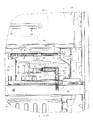
(第3実施形態)
図13は第3実施形態を示す。この第3実施形態では、ミスト放出手段を構成する静電霧化装置75におけるミスト発生ユニット76の構成が、第1実施形態とは異なっている。
ミスト発生ユニット76は、ミスト放出部77と、このミスト放出部77に水分を供給する給水部78とを備えている。給水部78は、正面から見て円形をなす円形部78aと、この円形部78aから下方に延びる垂直部78bとを有していて、ケース79内に第1実施形態と同様な保水材55を収容して構成されている。垂直部78bの下端部は、ダクト構成部材46の下部、前記冷蔵用冷却器室36の前部の段部36b(図8参照)の孔を貫通し、冷蔵用冷却器室36内に設けられた貯水容器56内に上方から挿入されている。給水部78における円形部78aおよび垂直部78bは、冷気ダクト34における冷蔵用冷却器室36の前部壁36aに平行となるように当該前部壁36aに沿って配置されている。
(Third embodiment)
FIG. 13 shows a third embodiment. In this 3rd Embodiment, the structure of the mist generation | occurrence | production unit 76 in the electrostatic atomizer 75 which comprises a mist discharge | release means differs from 1st Embodiment.
The mist generating unit 76 includes a mist discharge unit 77 and a water supply unit 78 that supplies moisture to the mist discharge unit 77. The water supply part 78 has a circular part 78a that is circular when viewed from the front, and a vertical part 78b that extends downward from the circular part 78a, and a water retaining material 55 similar to that of the first embodiment is placed in the case 79. Contained and configured. The lower end portion of the vertical portion 78b passes through the lower portion of the duct component member 46 and the hole of the step portion 36b (see FIG. 8) in the front portion of the refrigeration cooler chamber 36, and is provided in the refrigeration cooler chamber 36. The water storage container 56 is inserted from above. The circular portion 78a and the vertical portion 78b in the water supply portion 78 are arranged along the front wall 36a so as to be parallel to the front wall 36a of the refrigeration cooler chamber 36 in the cold air duct 34.
ミスト放出部77は、それぞれ突部を構成する複数本のミスト放出ピン57によって構成されている。ミスト放出ピン57は、円形部78aの外周部に放射状に設けられている。したがって、ミスト放出部77は、異なる方向に向けて突出する複数のミスト放出ピン57(突部)によって構成されている。各ミスト放出ピン57の基端部は、ケース79を貫通して保水材55に接触している。各ミスト放出ピン57も、冷気ダクト34における冷蔵用冷却器室36の前部壁36aに平行となるように当該前部壁36aに沿って配置されている。
The mist discharge part 77 is comprised by the several mist discharge | release pin 57 which each comprises a protrusion. The mist discharge pins 57 are provided radially on the outer peripheral portion of the circular portion 78a. Therefore, the mist discharge | release part 77 is comprised by the several mist discharge | release pin 57 (protrusion part) which protrudes toward a different direction. The base end portion of each mist discharge pin 57 passes through the case 79 and is in contact with the water retaining material 55. Each mist discharge pin 57 is also arranged along the front wall 36 a so as to be parallel to the front wall 36 a of the refrigeration cooler chamber 36 in the cold air duct 34.
給水部78における円形部78aの左部には、左側方へ突出する突出部78cが設けられていて、その突出部78cに受電ピン58が左向きに突出する状態で設けられている。その受電ピン58が、電源装置52側の給電端子61に接続されている。ミスト用専用ダクト45内(ミスト放出部72)に風を供給するための風供給口62aは、冷蔵用冷却器室36の前部壁36aにあって給水部78の円形部78aの上部と下部に対応するように、上下に2個形成されている。
A protruding portion 78c that protrudes to the left is provided on the left side of the circular portion 78a in the water supply portion 78, and the power receiving pin 58 is provided in a state of protruding to the left in the protruding portion 78c. The power reception pin 58 is connected to the power supply terminal 61 on the power supply device 52 side. A wind supply port 62a for supplying wind into the mist exclusive duct 45 (mist discharge section 72) is located on the front wall 36a of the refrigeration cooler chamber 36 and above and below the circular section 78a of the water supply section 78. Two pieces are formed on the top and bottom to correspond to the above.
この構成において、貯水容器56内に貯留された水が保水材55により吸い上げられて、各ミスト放出ピン57に供給される。また、電源装置52からの負の高電圧が、受電ピン58から、保水材55の水分を介して各ミスト放出ピン57に印加され、これに基づき、各ミスト放出ピン57から微細なミストが放出される。各ミスト放出ピン57から放出されたミストは、第1実施形態と同様に、風供給口62aからミスト用専用ダクト45内に供給された風に乗って、複数のミスト吹出口(冷蔵室用ミスト吹出口63a、チルド室用ミスト吹出口65、卵ケース用ミスト吹出口66、野菜室用ミスト吹出口67)から冷蔵室3、チルド室14、卵ケース15、ならびに野菜室4といった複数の供給先へ供給されるようになる。
In this configuration, the water stored in the water storage container 56 is sucked up by the water retaining material 55 and supplied to each mist discharge pin 57. Further, a negative high voltage from the power supply device 52 is applied to each mist discharge pin 57 from the power receiving pin 58 through the moisture of the water retaining material 55, and based on this, fine mist is discharged from each mist discharge pin 57. Is done. The mist discharged from each mist discharge pin 57 rides on the wind supplied from the wind supply port 62a into the mist dedicated duct 45 as in the first embodiment, and a plurality of mist outlets (refrigeration chamber mists). A plurality of supply destinations such as the air outlet 63a, the mist outlet 65 for the chilled chamber, the mist outlet 66 for the egg case, the mist outlet 67 for the vegetable compartment, and the refrigerator compartment 3, the chilled compartment 14, the egg case 15, and the vegetable compartment 4 Will be supplied to.
このような第3実施形態においては、特に、ミスト放出ピン57が放射状に配置されているから、第1実施形態の場合よりもミストを一層多方向へ放出することができる利点がある。
In such 3rd Embodiment, since the mist discharge | release pin 57 is arrange | positioned radially, there exists an advantage which can discharge | release mist further in many directions rather than the case of 1st Embodiment.
(その他の実施形態)
ミスト放出手段としては、静電霧化装置に限られず、例えば、貯水部に貯留された水を、超音波振動子の超音波振動により霧化させてミストを放出させる、超音波式霧化装置を用いるようにしてもよい。
(Other embodiments)
The mist discharge means is not limited to the electrostatic atomizer, but, for example, an ultrasonic atomizer that discharges mist by atomizing water stored in a water storage section by ultrasonic vibration of an ultrasonic vibrator. May be used.
また、ミスト放出手段から放出されたミストを吹き出すためのミスト吹出口としては、冷蔵室用ミスト吹出口63aおよび卵ケース用ミスト吹出口66はなくてもよい。
以上のように本実施形態の冷蔵庫によると、ミスト放出部から放出されたミストを、冷却器通過前の空気の風を利用して貯蔵室に供給する構成としたので、貯蔵室が冷え過ぎたり、ミスト放出部が凍結したりすることを防止することができる。
Further, the mist outlet for the refrigeration chamber 63a and the egg case mist outlet 66 may be omitted as the mist outlet for blowing out the mist discharged from the mist discharging means.
As described above, according to the refrigerator of the present embodiment, since the mist discharged from the mist discharge unit is supplied to the storage room using the wind of air before passing through the cooler, the storage room is too cold. It is possible to prevent the mist discharge part from freezing.
本発明のいくつかの実施形態を説明したが、これらの実施形態は、例として提示したものであり、発明の範囲を限定することは意図していない。これら新規な実施形態は、その他の様々な形態で実施されることが可能であり、発明の要旨を逸脱しない範囲で、種々の省略、置き換え、変更を行うことができる。これら実施形態やその変形は、発明の範囲や要旨に含まれるとともに、特許請求の範囲に記載された発明とその均等の範囲に含まれる。
Although several embodiments of the present invention have been described, these embodiments are presented by way of example and are not intended to limit the scope of the invention. These novel embodiments can be implemented in various other forms, and various omissions, replacements, and changes can be made without departing from the scope of the invention. These embodiments and modifications thereof are included in the scope and gist of the invention, and are included in the invention described in the claims and the equivalents thereof.