以下、複数の実施形態の冷蔵庫を、図面を参照して説明する。なお、各実施形態において実質的に同一の構成部位には同一の符号を付し、説明を省略する。また、冷蔵庫本体に対して扉側(例えば図1において左側)を前面として説明する。
Hereinafter, the refrigerator of several embodiment is demonstrated with reference to drawings. In addition, in each embodiment, the same code | symbol is attached | subjected to the substantially same component, and description is abbreviate | omitted. Moreover, the door side (for example, the left side in FIG. 1) is demonstrated as a front surface with respect to the refrigerator main body.
(第1実施形態)
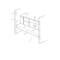
まず、第1実施形態について、図1〜図9を参照して説明する。図1および図2に示すように、冷蔵庫本体1は、前面が開口した縦長矩形箱状の断熱箱体2内に、上下方向に並んで配置された複数の貯蔵室を有している。具体的には、断熱箱体2内には、上段から順に、貯蔵室として、冷蔵室3、野菜室4が設けられ、その下方に製氷室5と小冷凍室6が左右に並べて設けられ、これらの下方に冷凍室7が設けられている。製氷室5内には、周知の自動製氷装置8(図1参照)が設けられている。断熱箱体2は、基本的には、鋼板製の外箱2aと、合成樹脂製の内箱2bと、外箱2aと内箱2bとの間に設けられた断熱材2cとから構成されている。
(First embodiment)
First, a first embodiment will be described with reference to FIGS. As shown in FIGS. 1 and 2, the refrigerator main body 1 has a plurality of storage chambers arranged side by side in a vertical direction in a vertically long rectangular box-shaped heat insulating box 2 having an open front surface. Specifically, in the heat insulation box 2, a refrigeration room 3 and a vegetable room 4 are provided as storage rooms in order from the top, and an ice making room 5 and a small freezer room 6 are provided side by side on the lower side. A freezer compartment 7 is provided below these. A known automatic ice making device 8 (see FIG. 1) is provided in the ice making chamber 5. The heat insulating box 2 is basically composed of a steel plate outer box 2a, a synthetic resin inner box 2b, and a heat insulating material 2c provided between the outer box 2a and the inner box 2b. Yes.
冷蔵室3および野菜室4は、いずれも冷蔵温度帯(例えば1〜4℃)の貯蔵室であり、冷蔵室3と野菜室4との間は、プラスチック製の仕切壁10により上下に仕切られている。冷蔵室3の前面部には、図1に示すように、ヒンジ開閉式の断熱扉3aが設けられている。野菜室4の前面部には、引出し式の断熱扉4aが設けられている。断熱扉4aの背面部には、貯蔵容器を構成する下部ケース11が連結されている。下部ケース11の上部の後部には、下部ケース11よりも小型の上部ケース12が設けられている。
The refrigerator compartment 3 and the vegetable compartment 4 are both storage compartments in a refrigerated temperature zone (for example, 1 to 4 ° C.), and the refrigerator compartment 3 and the vegetable compartment 4 are partitioned vertically by a plastic partition wall 10. ing. As shown in FIG. 1, a hinged heat insulating door 3 a is provided on the front surface of the refrigerator compartment 3. A drawer-type heat insulating door 4 a is provided on the front surface of the vegetable compartment 4. The lower case 11 which comprises a storage container is connected with the back surface part of the heat insulation door 4a. An upper case 12 that is smaller than the lower case 11 is provided at the rear of the upper portion of the lower case 11.
冷蔵室3内は、複数の棚板13により上下に複数段に区切られている。図3に示すように、冷蔵室3内の最下部(仕切壁10の上部)において、右側にはチルド室14が設けられ、その左側には卵ケース15および小物ケース16が上下に設けられ、さらに、これらの左側には貯水タンク17が設けられている。貯水タンク17は、自動製氷装置8の製氷皿8aに供給する水を貯留するためのものである。チルド室14には、チルドケース18が出し入れ可能に設けられている。
The inside of the refrigerator compartment 3 is divided into a plurality of stages vertically by a plurality of shelf boards 13. As shown in FIG. 3, in the lowermost part (the upper part of the partition wall 10) in the refrigerator compartment 3, a chilled chamber 14 is provided on the right side, and an egg case 15 and an accessory case 16 are provided vertically on the left side thereof. Further, a water storage tank 17 is provided on the left side of these. The water storage tank 17 is for storing water to be supplied to the ice tray 8 a of the automatic ice making device 8. A chilled case 18 is provided in the chilled chamber 14 so that it can be taken in and out.
製氷室5、小冷凍室6および冷凍室7は、いずれも冷凍温度帯(例えば−10〜−20℃)の貯蔵室である。また、野菜室4と、製氷室5および小冷凍室6との間は、図1に示すように断熱仕切壁19により上下に仕切られている。製氷室5の前面部には、引出し式の断熱扉5aが設けられている。断熱扉5aの後方には、貯氷容器20が連結されている。小冷凍室6の前面部にも、図示はしないが貯蔵容器が連結された引出し式の断熱扉が設けられている。冷凍室7の前面部にも、貯蔵容器22が連結された引出し式の断熱扉7aが設けられている。
The ice making room 5, the small freezer room 6, and the freezer room 7 are all storage rooms in a freezing temperature zone (for example, −10 to −20 ° C.). Further, the vegetable compartment 4 and the ice making compartment 5 and the small freezer compartment 6 are vertically partitioned by a heat insulating partition wall 19 as shown in FIG. A drawer-type heat insulating door 5 a is provided on the front surface of the ice making chamber 5. An ice storage container 20 is connected to the rear of the heat insulating door 5a. Although not shown, a drawer-type heat insulating door connected to a storage container is also provided on the front surface of the small freezer compartment 6. A drawer-type heat insulating door 7 a to which a storage container 22 is connected is also provided on the front surface of the freezer compartment 7.
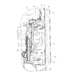
冷蔵庫本体1には、詳しく図示はしないが、冷蔵用冷却器24および冷凍用冷却器25の2つの冷却器を備える冷凍サイクルが組み込まれている。冷蔵用冷却器24は、冷蔵室3および野菜室4を冷却するための冷気を生成するものであり、冷蔵庫本体1の背面部に設けられている。冷凍用冷却器25は、製氷室5、小冷凍室6および冷凍室7を冷却するための冷気を生成するものであり、冷蔵庫本体1の背面部であって冷蔵用冷却器24の下方に設けられている。冷蔵庫本体1の下部背面部には、機械室26が設けられている。詳しく図示はしないが、この機械室26内には、上述の冷凍サイクルを構成する圧縮機27、凝縮器(図示せず)、圧縮機27および凝縮器を冷却するための冷却ファン(図示せず)、除霜水蒸発皿28などが設けられている。
Although not shown in detail, the refrigerator main body 1 incorporates a refrigeration cycle including two coolers, a refrigeration cooler 24 and a refrigeration cooler 25. The refrigerating cooler 24 generates cool air for cooling the refrigerating room 3 and the vegetable room 4, and is provided on the back surface of the refrigerator body 1. The refrigeration cooler 25 generates cold air for cooling the ice making chamber 5, the small freezer compartment 6, and the freezer compartment 7, and is provided at the back of the refrigerator body 1 and below the refrigeration cooler 24. It has been. A machine room 26 is provided on the lower back portion of the refrigerator body 1. Although not shown in detail, this machine room 26 has a compressor 27, a condenser (not shown), and a cooling fan (not shown) for cooling the compressor 27 and the condenser constituting the above-described refrigeration cycle. ), A defrosted water evaporating dish 28 and the like are provided.
冷蔵庫本体1の背面下部寄り部分には、全体を制御するマイコン等を実装した制御装置29が設けられている。なお、図示はしないが、冷蔵庫本体1に設けられる電気機器のアース線は、外箱2aなどを介して接地されている。
A control device 29 in which a microcomputer or the like for controlling the whole is mounted is provided near the lower rear portion of the refrigerator body 1. In addition, although not illustrated, the ground wire of the electric equipment provided in the refrigerator main body 1 is grounded via the outer box 2a or the like.
冷蔵庫本体1内の冷凍室7の背面部には、冷凍用冷却器室30が設けられている。冷凍用冷却器室30内には、冷凍用冷却器25、除霜用ヒータ(図示せず)、送風手段たる冷凍用送風ファン31などが設けられている。冷凍用送風ファン31は、ファンが回転することによる送風作用によって風を発生させて冷凍用冷却器25によって生成した冷気を循環させるものであり、冷凍用冷却器25の上方に設けられている。冷凍用冷却器室30の前面の中間部には、冷気吹出口30aが設けられ、下部には、戻り口30bが設けられている。
A refrigeration cooler chamber 30 is provided on the back surface of the freezer chamber 7 in the refrigerator body 1. In the refrigeration cooler chamber 30, a refrigeration cooler 25, a defrost heater (not shown), a refrigeration blower fan 31 serving as a blowing means, and the like are provided. The refrigeration blower fan 31 circulates the cold air generated by the refrigeration cooler 25 by generating air by the blowing action caused by the rotation of the fan, and is provided above the refrigeration cooler 25. A cold air outlet 30a is provided in the middle part of the front surface of the freezer cooler chamber 30, and a return port 30b is provided in the lower part.
この構成において、冷凍用送風ファン31および冷凍サイクルが駆動されると、送風作用によって風が生成され、冷凍用冷却器25によって生成した冷気は、冷気吹出口30aから製氷室5、小冷凍室6、冷凍室7内に供給され、戻り口30bから冷凍用冷却器室30内に戻される循環をする。これにより、それら製氷室5、小冷凍室6および冷凍室7は冷却される。なお、冷凍用冷却器25の下方には、当該冷凍用冷却器25の除霜時の除霜水を受ける排水樋32が設けられている。その排水樋32に受けられた除霜水は、機械室26内に設けられた除霜水蒸発皿28に導かれ、除霜水蒸発皿28の所で蒸発される。
In this configuration, when the refrigeration blower fan 31 and the refrigeration cycle are driven, wind is generated by the air blowing action, and the cold air generated by the refrigeration cooler 25 is supplied from the cold air outlet 30a to the ice making chamber 5 and the small freezer compartment 6. Then, it is circulated in the freezer compartment 7 and returned to the freezer cooler compartment 30 from the return port 30b. Thereby, the ice making room 5, the small freezer room 6, and the freezer room 7 are cooled. A drainage basin 32 that receives defrost water when the refrigeration cooler 25 is defrosted is provided below the refrigeration cooler 25. The defrost water received by the drainage basin 32 is guided to the defrost water evaporating dish 28 provided in the machine room 26 and evaporated at the defrost water evaporating dish 28.
そして、冷蔵庫本体1内における冷蔵室3および野菜室4の後方には、冷蔵用冷却器24、冷気ダクト34、送風手段たる冷蔵用送風ファン35などが設けられている。即ち、冷蔵庫本体1内における冷蔵室3の最下段の後方(チルド室14の後方)には、冷気ダクト34の一部を構成する冷蔵用冷却器室36が設けられ、この冷蔵用冷却器室36内に冷蔵用冷却器24が設けられている。冷気ダクト34は、冷蔵用冷却器24によって生成した冷気を冷蔵室3および野菜室4に供給するための通路を形成するものである。冷蔵用送風ファン35は、ファンが回転することによる送風作用によって風を発生させ冷蔵用冷却器24によって生成した冷気を循環させるものであり、冷蔵用冷却器24の下方に設けられている。
In the refrigerator main body 1, a refrigeration cooler 24, a cold air duct 34, a refrigeration blower fan 35 serving as a blower, and the like are provided behind the refrigerator compartment 3 and the vegetable compartment 4. That is, a refrigeration cooler chamber 36 constituting a part of the cold air duct 34 is provided behind the lowermost stage of the refrigeration chamber 3 in the refrigerator main body 1 (behind the chilled chamber 14). A refrigeration cooler 24 is provided in 36. The cold air duct 34 forms a passage for supplying the cold air generated by the refrigerating cooler 24 to the refrigerating room 3 and the vegetable room 4. The refrigeration blower fan 35 circulates the cool air generated by the refrigeration cooler 24 by generating air by the blowing action caused by the rotation of the fan, and is provided below the refrigeration cooler 24.
冷蔵用冷却器室36の上方には、上方に延びる冷気供給ダクト37が設けられ、冷蔵用冷却器室36の上端部が冷気供給ダクト37の下端部に連通している。この場合、冷蔵用冷却器室36と冷気供給ダクト37とから冷気ダクト34が構成される。冷蔵用冷却器室36の前部壁36aは、冷気供給ダクト37よりも前方に膨出している。また、その前部壁36aの背面側(冷蔵用冷却器24側)には、冷蔵用冷却器24の前面を覆う断熱性を有する断熱材38が設けられている。冷気供給ダクト37の前部には、冷蔵室3内に開口する冷気供給口39が複数個設けられている。
A cool air supply duct 37 extending upward is provided above the refrigerating cooler chamber 36, and an upper end portion of the refrigerating cooler chamber 36 communicates with a lower end portion of the cool air supply duct 37. In this case, the cold air duct 34 is constituted by the refrigeration cooler chamber 36 and the cold air supply duct 37. The front wall 36 a of the refrigeration cooler chamber 36 bulges forward from the cold air supply duct 37. In addition, a heat insulating material 38 having heat insulation covering the front surface of the refrigeration cooler 24 is provided on the back side (the refrigeration cooler 24 side) of the front wall 36a. In front of the cold air supply duct 37, a plurality of cold air supply ports 39 that open into the refrigerator compartment 3 are provided.
冷蔵用冷却器室36内の下部であって冷蔵用冷却器24の下方には、排水樋40が設けられている。排水樋40は、冷蔵用冷却器24からの除霜水を受けるものである。この排水樋40に受けられた除霜水も、排水樋32で受けられた除霜水と同様に、機械室26内に設けられた除霜水蒸発皿28に導かれ、除霜水蒸発皿28の所で蒸発される。排水樋40の左右の長さ寸法および前後の奥行き寸法は、冷蔵用冷却器24の左右の長さ寸法および前後の奥行き寸法よりも大きく、冷蔵用冷却器24から滴下する除霜水をすべて受けられる大きさに構成されている。
A drainage basin 40 is provided below the refrigeration cooler chamber 36 and below the refrigeration cooler 24. The drainage basin 40 receives defrosted water from the refrigeration cooler 24. The defrost water received by the drainage basin 40 is guided to the defrosting water evaporating dish 28 provided in the machine room 26 in the same manner as the defrosting water received by the drainage basin 32, and the defrosting water evaporating dish is provided. It is evaporated at 28. The left and right length dimensions and the front and rear depth dimensions of the drainage basin 40 are larger than the left and right length dimensions and the front and rear depth dimensions of the refrigeration cooler 24, and receive all the defrost water dripping from the refrigeration cooler 24. It is configured in the size that can be.
野菜室4の後方には、送風ダクト42が設けられている。送風ダクト42内には、送風手段たる冷蔵用送風ファン35が設けられている。送風ダクト42は、下端部に吸込み口43を有し、上端部が排水樋40をう回するようにして冷蔵用冷却器室36(冷気ダクト34)に連通している。吸込み口43は、野菜室4において開口している。なお、冷蔵室3の底部を構成する仕切壁10の後部の左右の両隅部には、図5に示すように、複数の連通口44が形成されている(図5には右側の連通口44のみ示す)。冷蔵室3は、連通口44を介して野菜室4と連通している。
An air duct 42 is provided behind the vegetable compartment 4. A refrigeration blower fan 35 serving as a blower is provided in the blower duct 42. The air duct 42 has a suction port 43 at its lower end, and communicates with the refrigeration cooler chamber 36 (cold air duct 34) so that the upper end of the air duct 42 bypasses the drain 40. The suction port 43 is open in the vegetable compartment 4. As shown in FIG. 5, a plurality of communication ports 44 are formed at the left and right corners of the rear portion of the partition wall 10 constituting the bottom of the refrigerator compartment 3 (the right communication port is shown in FIG. 5). 44 only). The refrigerator compartment 3 communicates with the vegetable compartment 4 through the communication port 44.
この構成において、冷蔵用送風ファン35が駆動されると送風作用によって、主に図1の白抜き矢印で示すように、風が発生する。すなわち、野菜室4内の空気は、吸込み口43から冷蔵用送風ファン35側に吸い込まれ、送風ダクト42側へ吹き出される。送風ダクト42側へ吹き出された空気は、冷気ダクト34(冷蔵用冷却器室36および冷気供給ダクト37)を通り、複数の冷気供給口39から冷蔵室3内に吹き出される。冷蔵室3内に吹き出された空気は、連通口44を通して野菜室4内にも供給され、最終的に冷蔵用送風ファン35に吸い込まれる。このように、冷蔵用送風ファン35の送風作用により風の循環が行われる。この風の循環の過程中に冷凍サイクルが駆動されていると、冷蔵用冷却器室36内を通る空気が冷蔵用冷却器24によって冷却されて冷気となり、その冷気が冷蔵室3および野菜室4に供給されることによって、冷蔵室3および野菜室4が冷蔵温度帯の温度に冷却される。
In this configuration, when the refrigeration blower fan 35 is driven, wind is generated by the air blowing action as indicated mainly by the white arrows in FIG. That is, the air in the vegetable compartment 4 is sucked into the refrigeration blower fan 35 side from the suction port 43 and blown out to the blower duct 42 side. The air blown out to the air duct 42 side passes through the cold air duct 34 (the refrigeration cooler chamber 36 and the cold air supply duct 37) and is blown out into the refrigerating chamber 3 from the plurality of cold air supply ports 39. The air blown into the refrigerator compartment 3 is also supplied into the vegetable compartment 4 through the communication port 44 and is finally sucked into the refrigerator fan 35 for refrigerator. In this way, the wind is circulated by the blowing action of the refrigeration blower fan 35. When the refrigeration cycle is driven during the wind circulation process, the air passing through the refrigeration cooler chamber 36 is cooled by the refrigeration cooler 24 to become cold air, and the cold air is stored in the refrigerator compartment 3 and the vegetable compartment 4. , The refrigerator compartment 3 and the vegetable compartment 4 are cooled to temperatures in the refrigerator temperature zone.
冷気ダクト34のうち冷蔵用冷却器室36の前方でチルド室14の後方であって、図2、図4に示すように、冷蔵庫本体1を正面から見て右側には、発生室45が設けられている。この発生室45は、図5〜図8にも示すように、冷蔵用冷却器室36の前部壁36aと、前部壁36aの前面に着脱可能に装着された覆い部材46とによって囲われて形成されている。この場合、発生室45は、前部壁36aに沿って左右方向に長く、かつ前後方向の奥行き寸法が小さく、扁平な矩形箱状に形成されている。そして、この発生室45内には、ミストを発生するためのミスト発生装置を構成する静電霧化装置48の主体部が収容されている。
A generation chamber 45 is provided on the right side of the refrigerator main body 1 as viewed from the front, as shown in FIGS. 2 and 4, in front of the chilled cooler chamber 36 and behind the chilled chamber 14 in the cold air duct 34. It has been. As shown in FIGS. 5 to 8, the generation chamber 45 is surrounded by a front wall 36 a of the refrigeration cooler chamber 36 and a covering member 46 detachably mounted on the front surface of the front wall 36 a. Is formed. In this case, the generation chamber 45 is formed in a flat rectangular box shape that is long in the left-right direction along the front wall 36a and has a small depth dimension in the front-rear direction. And in this generating chamber 45, the main part of the electrostatic atomizer 48 which comprises the mist generator for generating mist is accommodated.
次に、静電霧化装置48について詳述する。
静電霧化装置48は、主体部として、図9に示すように、ミスト放出部50を有するミスト発生ユニット51(ミスト発生手段に相当)と、ミスト放出部50に負の高電圧を印加するための電源装置(トランス)52とを備えている。静電霧化装置48は、主体部以外にもミスト放出部50に水分を供給する給水部53を備えている。給水部53は、左右方向に延びる水平部53aと、この水平部53aの右端部から下方に延びる垂直部53bとを有している。給水部53は、正面から見て逆L字状をなしていて、角筒状で正面から見て逆L字状をなすケース54内に保水材55を収容して構成されている。したがって、給水部53は、水平部53aと垂直部53bとの間に屈折部53cを有している。水平部53aは、垂直部53bに一体に設けられていても、垂直部53bとは異なる部品としてもよい。水平部53aおよび垂直部53bは、冷気ダクト34における冷蔵用冷却器室36の前部壁36aに平行となるように当該前部壁36aに沿って配置されている。保水材55は、後述する貯水容器56に貯められた水(除霜水)を毛細管現象で吸い上げてミスト放出部50に供給するものであり、例えば繊維を絡ませたフェルト状のものであり、吸水性および保水性に優れている。保水材55は、吸水性および保水性に優れ、毛細管現象を行うことができるものであれば上述以外にもよく、例えば連続発泡体のものでもよい。給水部53の水平部53aは、発生室45内のやや右寄りに配置され、垂直部53bの下端部は、図8に示すように、覆い部材46の下部、冷蔵用冷却器室36の前部の段部36bを貫通して冷蔵用冷却器室36内の下部の前部に位置している。
Next, the electrostatic atomizer 48 will be described in detail.
As shown in FIG. 9, the electrostatic atomizer 48 applies a negative high voltage to the mist generating unit 51 (corresponding to the mist generating means) having the mist emitting unit 50 and the mist emitting unit 50 as the main part. Power supply device (transformer) 52 is provided. The electrostatic atomizer 48 includes a water supply unit 53 that supplies moisture to the mist discharge unit 50 in addition to the main body. The water supply part 53 has a horizontal part 53a extending in the left-right direction and a vertical part 53b extending downward from the right end part of the horizontal part 53a. The water supply unit 53 has an inverted L shape when viewed from the front, and is configured by accommodating a water retaining material 55 in a case 54 that is a rectangular tube shape and has an inverted L shape when viewed from the front. Therefore, the water supply part 53 has the refracting part 53c between the horizontal part 53a and the vertical part 53b. The horizontal portion 53a may be provided integrally with the vertical portion 53b or may be a component different from the vertical portion 53b. The horizontal portion 53a and the vertical portion 53b are arranged along the front wall 36a so as to be parallel to the front wall 36a of the refrigeration cooler chamber 36 in the cold air duct 34. The water retaining material 55 sucks up water (defrosted water) stored in a water storage container 56, which will be described later, by capillary action and supplies it to the mist discharge unit 50. Excellent in properties and water retention. The water retaining material 55 may be other than the above as long as it is excellent in water absorption and water retention and can perform capillary action, and may be, for example, a continuous foam. The horizontal part 53a of the water supply part 53 is arranged slightly to the right in the generation chamber 45, and the lower end part of the vertical part 53b is the lower part of the cover member 46 and the front part of the refrigeration cooler room 36 as shown in FIG. Is located at the front part of the lower part in the refrigerator compartment 36 for cold storage.
冷蔵用冷却器室36内の下部の前部には、貯水部を構成する貯水容器56(図8参照)が設けられている。この貯水容器56は、冷蔵用冷却器24と排水樋40との間で、かつ給水部53の下方に設けられている。そして、貯水容器56は、前部が冷蔵用冷却器室36の前部壁に取り付けられ、後方へ突出する片持ち状態に設けられている。この貯水容器56内には、給水部53における垂直部53bの下端部が上方から挿入されている。貯水容器56は、冷蔵用冷却器24から滴下する除霜水を受けて貯留するものである。
A water storage container 56 (see FIG. 8) that constitutes a water storage section is provided in the front part of the lower part in the refrigerator room 36 for refrigeration. The water storage container 56 is provided between the refrigeration cooler 24 and the drain 40 and below the water supply unit 53. And the front part of the water storage container 56 is attached to the front part wall of the refrigerator room 36 for refrigeration, and is provided in the cantilever state which protrudes back. In this water storage container 56, the lower end part of the vertical part 53b in the water supply part 53 is inserted from above. The water storage container 56 receives and stores defrost water dripped from the refrigeration cooler 24.
貯水容器56は、排水樋40の貯水可能な高さよりも上方に位置していている。この貯水容器56の後部側の先端部には、当該貯水容器56を形成する周囲の壁よりも高さ方向が低い溢水部56aが形成されている。これにより、貯水容器56内に貯留された水が溢れる場合には、その溢水部56aから溢れることになる。溢水部56aから溢れた水は、排水樋40にて受けられ、除霜水蒸発皿28へ排出される。
The water storage container 56 is located above the height at which the drainage basin 40 can store water. An overflow portion 56 a whose height direction is lower than the surrounding wall forming the water storage container 56 is formed at the rear end portion of the water storage container 56. Thereby, when the water stored in the water storage container 56 overflows, it overflows from the overflow part 56a. The water overflowing from the overflow portion 56a is received by the drain 40 and discharged to the defrost water evaporating dish 28.
給水部53の水平部53aには、上述のミスト放出部50が設けられている。ミスト放出部50は、冷蔵室3の下部後部で野菜室4の上部後部かつチルド室14の後方に位置し、ミストを放出するための突部をなす複数本のミスト放出ピン57によって構成されている。複数本のミスト放出ピン57は、水平部53aの上部側に上向きに突出するように配置され、この場合4本が左右方向の横一列状に並んで配置されている。さらに、他の複数本のミスト放出ピン57は、水平部53aの下部側に下向きに突出するように配置され、この場合4本が左右方向の横一列状に並んで配置されている。すなわち、ミスト放出部50は、異なる方向、この場合上下方向に向けて突出する複数本のミスト放出ピン57により構成されている。また、ミスト放出部50は、複数本のミスト放出ピン57が、給水部53における水平部53aを間にして上下の反対方向に延びるように配置されている。さらに、複数本のミスト放出ピン57は、上下2段に配置されている。各ミスト放出ピン57は、冷気ダクト34における冷蔵用冷却器室36の前部壁36aに平行に配置されている。
The horizontal portion 53 a of the water supply unit 53 is provided with the mist discharge unit 50 described above. The mist discharge part 50 is located at the lower rear part of the refrigerator compartment 3 and at the upper rear part of the vegetable compartment 4 and at the rear of the chilled room 14, and is constituted by a plurality of mist discharge pins 57 that form protrusions for discharging mist. Yes. The plurality of mist discharge pins 57 are arranged so as to protrude upward on the upper side of the horizontal portion 53a. In this case, four mist discharge pins 57 are arranged side by side in the horizontal direction. Further, the other plurality of mist discharge pins 57 are arranged so as to protrude downward on the lower side of the horizontal portion 53a. In this case, four mist discharge pins 57 are arranged in a horizontal row in the left-right direction. That is, the mist discharge part 50 is comprised by the several mist discharge | release pin 57 which protrudes toward a different direction, and an up-down direction in this case. Moreover, the mist discharge | release part 50 is arrange | positioned so that the several mist discharge | release pin 57 may be extended in the up-and-down opposite direction between the horizontal parts 53a in the water supply part 53. Further, the plurality of mist discharge pins 57 are arranged in two upper and lower stages. Each mist discharge pin 57 is arranged in parallel to the front wall 36 a of the refrigeration cooler chamber 36 in the cold air duct 34.
各ミスト放出ピン57は、上述したようにミストが発生する部分であり、例えば、ポリエステル繊維と、導電性物質としてのカーボン繊維を混ぜて撚り合わせてピン状(棒状)に形成したもので、保水性及び水の吸い上げ特性を有するとともに、導電性を有している。各ミスト放出ピン57には、白金ナノコロイドが担持されている。白金ナノコロイドは、例えば、当該白金ナノコロイドを含む処理液にミスト放出ピン57を浸漬して、これを焼成することによって得られる。各ミスト放出ピン57の基端部は、給水部53のケース54を貫通して保水材55に接触している。給水部53における水平部53aの左端部には、受電用の電極を構成する受電ピン58が左向きに突出して設けられている。受電ピン58の基端部は、ケース54内において保水材55に接触している。
Each mist discharge pin 57 is a portion where mist is generated as described above. For example, a polyester fiber and a carbon fiber as a conductive material are mixed and twisted to form a pin shape (bar shape). It has conductivity and water uptake characteristics, and also has conductivity. Each mist release pin 57 carries platinum nanocolloid. The platinum nanocolloid is obtained, for example, by immersing the mist release pin 57 in a treatment solution containing the platinum nanocolloid and baking it. The base end portion of each mist discharge pin 57 passes through the case 54 of the water supply portion 53 and is in contact with the water retaining material 55. At the left end portion of the horizontal portion 53a in the water supply portion 53, a power receiving pin 58 constituting a power receiving electrode is provided so as to protrude leftward. The base end portion of the power receiving pin 58 is in contact with the water retaining material 55 in the case 54.
電源装置52は、発生室45内において、ミスト発生ユニット51の左側に設けられている。電源装置52の右端部には、リード線60が接続された、ファストン端子からなる給電端子61が設けられている。給電端子61は、ミスト発生ユニット51の受電ピン58と接続している。
電源装置52は、周知のように、高周波電源(交流電源)を直流に変換する高圧トランスを含む整流回路、昇圧回路などを備えていて、負の高電圧(例えば−6kV)を発生させ、給電端子61を介して受電ピン58に出力するようになっている。
これにより、電源装置52からの負の高電圧が、受電ピン58から、保水材55の水分を介して各ミスト放出ピン57に印加され、各ミスト放出ピン57が負に帯電するようになっている。
The power supply device 52 is provided on the left side of the mist generation unit 51 in the generation chamber 45. At the right end of the power supply device 52, a power supply terminal 61 composed of a Faston terminal to which a lead wire 60 is connected is provided. The power supply terminal 61 is connected to the power reception pin 58 of the mist generating unit 51.
As is well known, the power supply device 52 includes a rectifier circuit, a booster circuit, and the like including a high-voltage transformer that converts a high-frequency power supply (AC power supply) into direct current, and generates a negative high voltage (for example, −6 kV) to supply power. The power is output to the power receiving pin 58 via the terminal 61.
As a result, a negative high voltage from the power supply device 52 is applied to each mist discharge pin 57 from the power receiving pin 58 via the moisture of the water retaining material 55, and each mist discharge pin 57 is negatively charged. Yes.
このように構成された静電霧化装置48においては、貯水容器56の水が保水材55による毛細管現象で吸い上げられて各ミスト放出ピン57に供給された状態で、各ミスト放出ピン57に、電源装置52からの負の高電圧が印加される。このとき、各ミスト放出ピン57の先端部に電荷が集中し、当該先端部に含まれる水に表面張力を超えるエネルギーが与えられる。これにより、各ミスト放出ピン57の先端部の水が分裂(レイリー分裂)して、先端部から微細なミスト状に放出されるようになる(静電霧化現象)。ここで、ミスト状に放出された水粒子は、負に帯電しており、そのエネルギーによって生成したヒドロキシラジカルを含んでいる。
In the electrostatic atomizer 48 configured as described above, the water in the water storage container 56 is sucked up by a capillary phenomenon by the water retaining material 55 and supplied to each mist discharge pin 57. A negative high voltage from the power supply device 52 is applied. At this time, electric charges concentrate on the tip of each mist discharge pin 57, and energy exceeding the surface tension is given to the water contained in the tip. As a result, the water at the tip of each mist discharge pin 57 is split (Rayleigh split) and discharged from the tip into a fine mist (electrostatic atomization phenomenon). Here, the water particles released in the form of mist are negatively charged and contain hydroxy radicals generated by the energy.
したがって、強い酸化作用を有するヒドロキシラジカルが各ミスト放出ピン57からミストとともに放出されるようになり、当該ヒドロキシラジカルの作用によって除菌や脱臭が可能となる。この場合、負に帯電したミスト放出ピン57に対応する対極を設けていない。そのため、ミスト放出ピン57からの放電自体が非常に穏やかになり、放電電極と対極との間でコロナ放電が発生することなく、有害ガス(オゾンや、当該オゾンが空気中の窒素を酸化することによって発生する窒素酸化物、亜硝酸、硝酸など)の発生を抑えることができる。
Therefore, the hydroxyl radical having a strong oxidizing action is released together with the mist from each mist releasing pin 57, and sterilization and deodorization are enabled by the action of the hydroxy radical. In this case, the counter electrode corresponding to the negatively charged mist discharge pin 57 is not provided. Therefore, the discharge itself from the mist emitting pin 57 becomes very gentle, and no harmful gas (ozone or the ozone oxidizes nitrogen in the air without generating corona discharge between the discharge electrode and the counter electrode). Generation of nitrogen oxides, nitrous acid, nitric acid, etc. generated by the
ここで、ミスト放出ピン57(ミスト放出部50)は、ヒドロキシラジカルという除菌成分(脱臭成分でもある)を放出する除菌成分放出手段(脱臭成分放出手段でもある)ということができ、静電霧化装置48は、除菌成分発生手段(脱臭成分発生手段)ということができる。
Here, the mist releasing pin 57 (mist releasing part 50) can be called a disinfecting component releasing means (also a deodorizing component releasing means) for releasing a disinfecting component (also a deodorizing component) called a hydroxy radical, The atomization device 48 can be referred to as a sterilization component generation means (deodorization component generation means).
次に、発生室45について詳しく説明する。
発生室45は、上述したように、内部にミスト発生ユニット51を収容している。これにより、ミスト発生ユニット51の駆動によって発生したミストは発生室45内に溜められやすくなる。したがって、ミスト発生ユニット51で生成されたミストにおいて時間経過などによって濃度ムラが生じた場合でも、生成されたミストは発生室45内に拡散されるため、発生室45内のミストの濃度はほぼ均一になりやすい。
Next, the generation chamber 45 will be described in detail.
As described above, the generation chamber 45 accommodates the mist generation unit 51 inside. Accordingly, the mist generated by driving the mist generating unit 51 is easily stored in the generation chamber 45. Therefore, even when density unevenness occurs in the mist generated by the mist generation unit 51 due to the passage of time or the like, the generated mist is diffused into the generation chamber 45, so that the concentration of mist in the generation chamber 45 is substantially uniform. It is easy to become.
発生室45は、後壁を構成する冷蔵用冷却器室36の前部壁36aに風供給口62(図4、図7参照)を有している。風供給口62は、冷蔵用送風ファン35の送風作用によって発生した風であって冷蔵用冷却器室36を通る風の一部を発生室45内に取り込むための開口である(風の流れを図4、図7の矢印A1で示す)。風供給口62は、ミスト放出部50におけるミスト放出ピン57と対向する位置とは異なる位置、この場合、ミスト放出部50よりも左方で、電源装置52の上方および冷蔵用冷却器24の上方に設けられている。この風供給口62は、図7に示すように後部が断熱材38を貫通して冷気ダクト34における冷蔵用冷却器室36と連通し、前部が発生室45と連通している。これにより、冷蔵用冷却器室36を通る風の一部は、後方から前方に向かって発生室45内に供給される。
The generation chamber 45 has a wind supply port 62 (see FIGS. 4 and 7) on the front wall 36a of the refrigeration cooler chamber 36 constituting the rear wall. The wind supply port 62 is an opening for taking a part of the wind generated by the blowing action of the refrigeration blower fan 35 and passing through the refrigeration cooler chamber 36 into the generation chamber 45 (the flow of wind is reduced). (Indicated by arrow A1 in FIGS. 4 and 7). The wind supply port 62 is located at a position different from the position facing the mist discharge pin 57 in the mist discharge section 50, in this case, on the left side of the mist discharge section 50, above the power supply device 52 and above the refrigeration cooler 24. Is provided. As shown in FIG. 7, the wind supply port 62 has a rear portion that penetrates the heat insulating material 38 and communicates with the refrigeration cooler chamber 36 in the cold air duct 34, and a front portion communicates with the generation chamber 45. Thereby, a part of the wind passing through the refrigeration cooler chamber 36 is supplied into the generation chamber 45 from the rear to the front.
また、発生室45は、複数の貯蔵室(冷蔵室3、チルド室14、卵ケース15ならびに野菜室4)に対応して複数のミスト吹出口64、65、66、67を有している。これらミスト吹出口64、65、66、67は、風供給口62と対向する位置とは異なる位置であって、ミスト発生ユニット51の周囲に設けられ、各貯蔵室にミストを供給するためのものである。
ミスト吹出口64は、風供給口62の上方に設けられた冷蔵室向けミスト用ダクト63(図4、図7参照)の下端部の開口であり、風供給口62よりも上方に位置し、ミスト放出ピン57と対向する位置とは異なる位置に設けられている。すなわち、ミスト吹出口64とミスト放出ピン57とは前後方向において対向していない。
The generation chamber 45 has a plurality of mist outlets 64, 65, 66, and 67 corresponding to a plurality of storage chambers (the refrigeration chamber 3, the chilled chamber 14, the egg case 15, and the vegetable chamber 4). These mist outlets 64, 65, 66, 67 are different from the positions facing the wind supply ports 62 and are provided around the mist generating unit 51 to supply mist to the respective storage chambers. It is.
The mist outlet 64 is an opening at the lower end of a mist duct 63 (see FIGS. 4 and 7) for a refrigerator compartment provided above the wind supply port 62, and is located above the wind supply port 62. It is provided at a position different from the position facing the mist discharge pin 57. That is, the mist outlet 64 and the mist discharge pin 57 are not opposed in the front-rear direction.
冷蔵室向けミスト用ダクト63は、冷蔵用冷却器室36の前部壁36aの背面側に位置して、上方に延びている。冷蔵室向けミスト用ダクト63の上端部は、冷気ダクト34における冷気供給ダクト37内に連通している。これにより、風供給口62から取り込んだ風は、発生室45の内周壁(覆い部材46の背面)に当たって向きがかわり、この風の一部がミスト吹出口64から吹出される。したがって、発生室45内でミスト発生ユニット51によって発生したミストは、風供給口62から取り込んだ風によって対流され、拡散されやすくなる。これにより、発生室45内のミストの濃度はより一層均一になりやすい。そして、発生室45内で対流されたミストの一部は、風供給口62から取り込んだ風の一部とともにミスト吹出口64、冷蔵室向けミスト用ダクト63、冷気供給ダクト37を通り、冷気供給口39から冷蔵室3に供給される(風の流れを図4、図7の矢印B1で示す)。
The refrigeration chamber mist duct 63 is located on the back side of the front wall 36a of the refrigeration cooler chamber 36 and extends upward. The upper end portion of the mist duct 63 for the refrigerator compartment is in communication with the cold air supply duct 37 in the cold air duct 34. As a result, the wind taken in from the wind supply port 62 strikes the inner peripheral wall of the generation chamber 45 (the back surface of the covering member 46) and changes its direction, and a part of this wind is blown out from the mist outlet 64. Therefore, the mist generated by the mist generating unit 51 in the generation chamber 45 is convected by the wind taken in from the wind supply port 62 and is easily diffused. Thereby, the density | concentration of the mist in the generation | occurrence | production chamber 45 tends to become still more uniform. A part of the mist convected in the generation chamber 45 passes through the mist outlet 64, the mist duct 63 for the refrigerator compartment, and the cold air supply duct 37 together with a part of the wind taken in from the wind supply port 62 to supply the cold air. It is supplied to the refrigerator compartment 3 from the mouth 39 (the flow of the wind is indicated by an arrow B1 in FIGS.
ミスト吹出口65は、図4、図7に示すように、覆い部材46の前面部であって風供給口62よりも上方で、ミスト放出ピン57と対向する位置とは異なる位置に設けられ、チルド室14と連通している。すなわち、ミスト吹出口65とミスト放出ピン57とは前後方向において対向していない。これにより、風供給口62から取り込んだ風は、発生室45の内周壁(覆い部材46の背面)に当たって向きがかわり、この風の一部がミスト吹出口65から吹出される。したがって、発生室45内で対流された上述のミストの一部は、風供給口62から取り込んだ風の一部とともにミスト吹出口65からチルド室14に供給される(風の流れを図4、図7の矢印B2で示す)。
As shown in FIGS. 4 and 7, the mist outlet 65 is provided at a position different from the position facing the mist discharge pin 57 on the front surface of the covering member 46 and above the wind supply port 62. It communicates with the chilled chamber 14. That is, the mist outlet 65 and the mist discharge pin 57 are not opposed in the front-rear direction. As a result, the wind taken in from the wind supply port 62 strikes the inner peripheral wall of the generating chamber 45 (the back surface of the covering member 46) and changes its direction, and a part of this wind is blown out from the mist outlet 65. Therefore, a part of the above-described mist convected in the generation chamber 45 is supplied to the chilled chamber 14 from the mist outlet 65 together with a part of the wind taken in from the wind supply port 62 (the flow of wind is shown in FIG. (Indicated by arrow B2 in FIG. 7).
ミスト吹出口66は、図4に示すように、覆い部材46のうち風供給口62よりも上方の左方で、ミスト放出ピン57と対向する位置とは異なる位置に設けられ、卵ケース15と連通している。すなわち、ミスト吹出口66とミスト放出ピン57とは前後方向において対向していない。これにより、風供給口62から取り込んだ風は、発生室45の内周壁(覆い部材46の背面)に当たって向きがかわり、この風の一部がミスト吹出口66から吹出される。したがって、発生室45内で対流された上述のミストの一部は、風供給口62から取り込んだ風の一部とともにミスト吹出口66から卵ケース15に供給される(風およびミストの流れを図4の矢印B3で示す)。
As shown in FIG. 4, the mist outlet 66 is provided on the left side of the covering member 46 above the wind supply port 62 at a position different from the position facing the mist discharge pin 57. Communicate. That is, the mist outlet 66 and the mist discharge pin 57 are not opposed in the front-rear direction. As a result, the wind taken in from the wind supply port 62 strikes the inner peripheral wall of the generating chamber 45 (the back surface of the covering member 46) and changes its direction, and a part of this wind is blown out from the mist outlet 66. Accordingly, a part of the mist described above convected in the generation chamber 45 is supplied to the egg case 15 from the mist outlet 66 together with a part of the wind taken in from the wind supply port 62 (the flow of wind and mist is illustrated). 4 as indicated by arrow B3).
ミスト吹出口67は、図5に示すように、発生室45の右下部、言い換えると風供給口62よりも下方の右方で、ミスト放出ピン57と対向する位置とは異なる位置に設けられ、野菜室4に連通口44を介して連通している。すなわち、ミスト吹出口67とミスト放出ピン57とは前後方向において対向していない。これにより、風供給口62から取り込んだ風は、発生室45の内周壁(覆い部材46の背面)に当たって向きがかわり、この風の一部がミスト吹出口67から吹出される。したがって、発生室45内で対流された上述のミストの一部は、風供給口62から取り込んだ風の一部とともにミスト吹出口67から連通口44を介して野菜室4に供給される。
As shown in FIG. 5, the mist outlet 67 is provided at a position different from the position facing the mist discharge pin 57 on the lower right side of the generation chamber 45, in other words, on the right side below the wind supply port 62. It communicates with the vegetable compartment 4 through a communication port 44. That is, the mist outlet 67 and the mist discharge pin 57 are not opposed in the front-rear direction. As a result, the wind taken in from the wind supply port 62 strikes the inner peripheral wall of the generating chamber 45 (the back surface of the covering member 46) and changes its direction, and a part of the wind is blown out from the mist outlet 67. Therefore, part of the mist described above convected in the generation chamber 45 is supplied to the vegetable compartment 4 from the mist outlet 67 through the communication port 44 together with part of the wind taken in from the wind supply port 62.
発生室45は、上部であってミスト放出部50の上方に位置させて、チルド室用風供給ダクト68(図4、図6、図8参照)を有している。チルド室用風供給ダクト68は、図8に示すように、後部が断熱材38を貫通して冷蔵用冷却器室36と連通し、前部が発生室45を貫通してチルド室14と連通している。したがって、冷蔵用冷却器室36を通る風の一部、すなわち冷気の一部は、チルド室用風供給ダクト68を通ってチルド室14に直接供給される(風の流れを図6、図8の矢印A2で示す)。
The generation chamber 45 has an chilled chamber wind supply duct 68 (see FIGS. 4, 6, and 8) that is located above the mist discharge unit 50 in the upper part. As shown in FIG. 8, the chilled chamber wind supply duct 68 has a rear portion passing through the heat insulating material 38 and communicating with the refrigeration cooler chamber 36, and a front portion passing through the generating chamber 45 and communicating with the chilled chamber 14. doing. Accordingly, a part of the wind passing through the refrigeration cooler chamber 36, that is, a part of the cool air is directly supplied to the chilled chamber 14 through the chilled chamber wind supply duct 68 (the flow of the wind is shown in FIGS. 6 and 8). Indicated by arrow A2).
次に、上記構成の作用について述べる。
冷蔵室3および野菜室4を冷却する際には、冷蔵用冷却器24によって冷却された冷気が、冷蔵用送風ファン35の送風作用によって発生した風によって、主に図1に白抜き矢印で示すように、冷気供給ダクト37を通り、複数の冷気供給口39から冷蔵室3に供給される。さらに、冷蔵用送風ファン35によって発生した風の一部がチルド室用風供給ダクト68からチルド室14に直接供給される(図6、図8の矢印A2参照)。冷蔵室3およびチルド室14に供給された冷気は、食品などの貯蔵物の冷却に寄与した後、合流して、連通口44から野菜室4にも供給される。野菜室4に供給された冷気は、野菜などの貯蔵物の冷却に寄与した後、吸込み口43から冷蔵用送風ファン35側に吸い込まれ、再び冷蔵用冷却器24により冷却されるという循環を繰り返す。
Next, the operation of the above configuration will be described.
When the refrigerator compartment 3 and the vegetable compartment 4 are cooled, the cold air cooled by the refrigerator refrigerator 24 is indicated mainly by white arrows in FIG. 1 due to the wind generated by the blowing action of the refrigerator fan 35 for refrigerator. As described above, the air passes through the cold air supply duct 37 and is supplied from the plurality of cold air supply ports 39 to the refrigerator compartment 3. Further, a part of the wind generated by the refrigeration blower fan 35 is directly supplied to the chilled chamber 14 from the chilled chamber wind supply duct 68 (see arrow A2 in FIGS. 6 and 8). The cool air supplied to the refrigerator compartment 3 and the chilled room 14 contributes to cooling of stored items such as food, and then merges and is supplied to the vegetable compartment 4 from the communication port 44. The cold air supplied to the vegetable compartment 4 contributes to the cooling of stored items such as vegetables, and is then sucked into the refrigeration fan 35 side from the suction port 43 and cooled again by the refrigeration cooler 24. .
また、この冷蔵室3および野菜室4の冷却時には、冷蔵用冷却器室36を通る風の一部が、図7に矢印A1で示すように、風供給口62から取り込まれ発生室45内に供給される。ここで、ミスト吹出口64、65、66、67が風供給口62と対向する位置とは異なる位置に設けられているので、風供給口62から取り込まれた風は、発生室45の内周壁(覆い部材46の背面)に当たって向きがかわり、風供給口62から取り込まれた風がミスト吹出口64、65、66、67のそれぞれから吹出される。
Further, when the refrigerator compartment 3 and the vegetable compartment 4 are cooled, a part of the wind passing through the refrigerator compartment 36 for refrigeration is taken in from the wind supply port 62 as shown by an arrow A1 in FIG. Supplied. Here, since the mist outlets 64, 65, 66, and 67 are provided at positions different from the positions facing the wind supply ports 62, the wind taken in from the wind supply ports 62 is the inner peripheral wall of the generation chamber 45. The direction is changed by hitting (the back surface of the covering member 46), and the wind taken in from the wind supply port 62 is blown out from each of the mist outlets 64, 65, 66, and 67.
このとき、静電霧化装置48が駆動されていると、ミスト発生ユニット51における複数の各ミスト放出ピン57から、上述したようにヒドロキシラジカルを含んだ微細なミストが放出される。放出されたミストは、発生室45で溜められ発生室内に拡散し、発生室45のミストの濃度はほぼ均一となる。そして、風が風供給口62から発生室45に取り込まれることにより、発生室45内のミストは拡散、対流されて、発生室45内のミストの濃度はより一層均一となる。そして、対流されて濃度がほぼ均一にされたミストの一部は、ミスト吹出口64から冷蔵室向けミスト用ダクト63および冷気供給ダクト37を介して冷蔵室3に、ミスト吹出口65からチルド室14に、ミスト吹出口66から卵ケース15に、ミスト吹出口67から連通口44を介して野菜室4にそれぞれ供給される。
At this time, when the electrostatic atomizer 48 is driven, fine mist containing hydroxy radicals is released from the plurality of mist release pins 57 in the mist generation unit 51 as described above. The released mist is stored in the generation chamber 45 and diffused into the generation chamber, and the concentration of the mist in the generation chamber 45 becomes substantially uniform. Then, when the wind is taken into the generation chamber 45 from the wind supply port 62, the mist in the generation chamber 45 is diffused and convected, and the concentration of the mist in the generation chamber 45 becomes more uniform. A part of the mist that has been convected to have a substantially uniform concentration is transferred from the mist outlet 64 to the refrigerator compartment 3 through the refrigeration chamber mist duct 63 and the cold air supply duct 37, and from the mist outlet 65 to the chilled chamber. 14, the mist outlet 66 is supplied to the egg case 15, and the mist outlet 67 is supplied to the vegetable compartment 4 through the communication port 44.
上記した第1実施形態によれば次のような効果を得ることができる。
ミスト発生ユニット51を発生室45内に設ける構成としたので、当該ミスト発生ユニットによって発生したミストは発生室45に溜まりやすくなる。これにより、ミスト発生ユニット51で生成されたミストに濃度ムラが生じても、発生室45内でミストが拡散するので、発生室45内のミストの濃度はほぼ均一となり、濃度がほぼ均一なミストをミスト吹出口64、65、66、67から貯蔵室(冷蔵室3、チルド室14、卵ケース15ならびに野菜室4)に供給することができる。
According to the first embodiment described above, the following effects can be obtained.
Since the mist generation unit 51 is provided in the generation chamber 45, the mist generated by the mist generation unit tends to accumulate in the generation chamber 45. As a result, even if density unevenness occurs in the mist generated by the mist generation unit 51, the mist diffuses in the generation chamber 45, so that the concentration of the mist in the generation chamber 45 becomes substantially uniform, and the mist has a substantially uniform concentration. Can be supplied from the mist outlets 64, 65, 66, 67 to the storage room (the refrigerated room 3, the chilled room 14, the egg case 15, and the vegetable room 4).
ミスト吹出口64、65、66、67を風供給口62と対向する位置とは異なる位置に設けているので、発生室45内のミストは風供給口62から取り込んだ風によって発生室45内で拡散、対流される。これにより、発生室45内のミストの濃度はより一層均一となり、より一層均一な濃度のミストをミスト吹出口64、65、66、67から貯蔵室に供給することができる。
ミスト吹出口64、65、66、67がミスト発生ユニット51を中心とした周囲に配置されているので、ミスト発生ユニット51から放出されたミストは、発生室45内に均一に拡散しやすくなる。これにより、発生室45内のミストの濃度をより一層均一にすることができる。
Since the mist outlets 64, 65, 66, and 67 are provided at positions different from the positions facing the wind supply port 62, the mist in the generation chamber 45 is generated in the generation chamber 45 by the wind taken in from the wind supply port 62. Diffusion and convection. Thereby, the density | concentration of the mist in the generation | occurrence | production chamber 45 becomes more uniform, and the mist of a more uniform density | concentration can be supplied to a storage chamber from the mist blower outlet 64,65,66,67.
Since the mist outlets 64, 65, 66, and 67 are arranged around the mist generating unit 51, the mist discharged from the mist generating unit 51 easily diffuses uniformly into the generation chamber 45. Thereby, the density | concentration of the mist in the generation | occurrence | production chamber 45 can be made still more uniform.
発生室45の複数のミスト吹出口64、65、66、67は、ミスト放出ピン57と対向する位置とは異なる位置に設けているので、万一、それらミスト吹出口64、65、66、67から発生室45内に手指や異物が挿入されたとしても、手指や異物がミスト放出ピン57に直接触れることを防止することができ、安全性を確保できる。
風供給口62とミスト放出部50(ミスト放出ピン57)とが対向する位置とは異なる位置に設けているので、風供給口62から発生室45内に取り込まれる風(冷却風)は、ミスト放出部50(ミスト放出ピン57)に直接は当たらない。これにより、ミスト放出ピン57が、風供給口62からの冷却風を直接受けて乾燥、凍結することを抑えることが可能になる。
Since the plurality of mist outlets 64, 65, 66, 67 of the generation chamber 45 are provided at positions different from the positions facing the mist discharge pin 57, the mist outlets 64, 65, 66, 67 should be used. Even if a finger or a foreign object is inserted into the generation chamber 45, the finger or the foreign object can be prevented from directly touching the mist discharge pin 57, and safety can be ensured.
Since the wind supply port 62 and the mist discharge part 50 (mist discharge pin 57) are provided at different positions, the wind (cooling air) taken into the generation chamber 45 from the wind supply port 62 is mist. It does not directly hit the discharge part 50 (mist discharge pin 57). As a result, it is possible to prevent the mist discharge pin 57 from directly receiving the cooling air from the air supply port 62 and drying and freezing.
ミスト発生装置を構成する静電霧化装置48は、ミストを放出するミスト放出部50と、ミスト放出部50に水分を供給する給水部53と、ミスト放出部50に負の電圧を印加する電源装置52とを備え、ミスト放出部50を、異なる方向に向けて突出する複数本のミスト放出ピン57により構成している。この構成により、ミスト発生用の突部の突出方向が一方向のみである場合とは違い、ミストの供給方向を複数方向にすることができ、ミストの供給範囲を広くすることができる。
The electrostatic atomizer 48 that constitutes the mist generator includes a mist discharge unit 50 that discharges mist, a water supply unit 53 that supplies moisture to the mist discharge unit 50, and a power source that applies a negative voltage to the mist discharge unit 50. The mist discharge | release part 50 is comprised by the several mist discharge | release pin 57 which protrudes toward a different direction. With this configuration, unlike the case where the protruding direction of the projection for generating mist is only one direction, the supply direction of mist can be a plurality of directions, and the supply range of mist can be widened.
ミスト放出部50は、ミスト放出ピン57が給水部53の水平部53aを間にして上下反対方向に延びる構成としたことにより、ミストを上方と下方にも放出でき、ミストの供給範囲を広くできる。さらに、複数の貯蔵室を上下方向に設け、発生室45が各貯蔵室に対応するミスト吹出口64、65、66、67を有するように構成したので、各貯蔵室とミスト放出ピン57との距離を極力短くすることができ、発生室45内のミストを効率よく各貯蔵室に供給することができる。
The mist discharge part 50 is configured such that the mist discharge pin 57 extends in the opposite direction up and down with the horizontal part 53a of the water supply part 53 therebetween, so that the mist can be discharged upward and downward, and the supply range of mist can be widened. . Furthermore, since the plurality of storage chambers are provided in the vertical direction and the generation chamber 45 is configured to have the mist outlets 64, 65, 66, 67 corresponding to the respective storage chambers, The distance can be shortened as much as possible, and the mist in the generation chamber 45 can be efficiently supplied to each storage chamber.
また、給水部53の水平部53aおよび各ミスト放出ピン57は、冷気ダクト34における冷蔵用冷却器室36の前部壁36aに平行となるように当該前部壁36aに沿って配置したことにより、前後方向の薄型化が可能になる。ミスト放出ピン57を上下2段に配置したことにより、コンパクト化が可能となる。
Further, the horizontal portion 53a of the water supply portion 53 and each mist discharge pin 57 are arranged along the front wall 36a so as to be parallel to the front wall 36a of the refrigeration cooler chamber 36 in the cold air duct 34. It is possible to reduce the thickness in the front-rear direction. By arranging the mist discharge pins 57 in two upper and lower stages, it is possible to make the apparatus compact.
ミスト放出部50は、ミスト放出ピン57が列状に複数並んで配置されている構成としたことにより、ミストの放出量を多くでき、ミストの供給範囲を一層広くすることができ、また、薄型化が可能になる。
冷蔵庫本体1には、冷蔵室3および野菜室4へ冷気を供給する冷気ダクト34が設けられ、発生室45は、その冷気ダクト34における冷蔵用冷却器室36の前部壁36aに沿って配置した。これにより、発生室45の薄型化が可能になる。
また、電源装置52およびミスト発生ユニット51を、冷気ダクト34における冷蔵用冷却器室36の前部壁36aに平行となるように当該前部壁36aに沿って配置したことにより、静電霧化装置48の奥行き方向の薄型化が可能になる。
The mist discharge unit 50 has a configuration in which a plurality of mist discharge pins 57 are arranged in a line, so that the amount of mist discharged can be increased, the supply range of mist can be further widened, and the thickness is reduced. Can be realized.
The refrigerator main body 1 is provided with a cold air duct 34 for supplying cold air to the refrigerating room 3 and the vegetable room 4, and the generation room 45 is arranged along the front wall 36 a of the refrigerating cooler room 36 in the cold air duct 34. did. Thereby, the generation chamber 45 can be thinned.
In addition, by arranging the power supply device 52 and the mist generating unit 51 along the front wall 36a so as to be parallel to the front wall 36a of the refrigeration cooler chamber 36 in the cold air duct 34, electrostatic atomization is achieved. The device 48 can be thinned in the depth direction.
給水部53は、屈折部53cを有し、屈折部53cの下方には水を貯留する貯水容器56が設けられ、貯水容器56に貯留された水を屈折部53cに供給可能な構成とした。これにより、貯水容器56の水を、屈折部53cを介してミスト放出ピン57に供給することができる。また、ミスト放出ピン57を、貯水容器56から離すことができるので、それらミスト放出ピン57と貯水容器56内の水との絶縁が可能になる。電源装置52は、ミスト放出部50を間にして屈折部53cの反対側に配置した。これにより、電源装置52を貯水容器56から一層離すことが可能になる。
The water supply unit 53 has a refracting unit 53c, a water storage container 56 for storing water is provided below the refracting unit 53c, and the water stored in the water storage container 56 can be supplied to the refracting unit 53c. Thereby, the water of the water storage container 56 can be supplied to the mist discharge | release pin 57 via the bending part 53c. Further, since the mist discharge pin 57 can be separated from the water storage container 56, the mist discharge pin 57 and the water in the water storage container 56 can be insulated. The power supply device 52 is disposed on the opposite side of the refraction part 53c with the mist emitting part 50 in between. Thereby, the power supply device 52 can be further separated from the water storage container 56.
ミスト放出ピン57に供給する水は、貯水容器56に貯留した冷蔵用冷却器24の除霜水を利用しているので、貯水容器56への給水を自動的に行うことができ、使用者が給水するという手間を省くことができる。
発生室45は、前部壁36aと、着脱可能に装着された覆い部材46とによって囲われて形成されているので、覆い部材46を取外すことにより、発生室45内のメンテナンスが容易にできる。
Since the water supplied to the mist discharge pin 57 uses the defrost water of the refrigeration cooler 24 stored in the water storage container 56, the water supply to the water storage container 56 can be automatically performed, and the user can The trouble of supplying water can be saved.
Since the generation chamber 45 is formed to be surrounded by the front wall 36a and the cover member 46 that is detachably mounted, the maintenance inside the generation chamber 45 can be easily performed by removing the cover member 46.
(第2実施形態)
第2実施形態について、図10〜図12を参照して説明する。
第2実施形態の冷蔵庫本体1は、図11に示すように冷却経路71aを形成する第1の経路部材71と、非冷却経路72aを形成する第2の経路部材72とを有している。
(Second Embodiment)
A second embodiment will be described with reference to FIGS.
The refrigerator main body 1 of 2nd Embodiment has the 1st path | route member 71 which forms the cooling path | route 71a, as shown in FIG. 11, and the 2nd path | route member 72 which forms the non-cooling path | route 72a.
冷却経路71aは、冷蔵用冷却器室36のうち冷蔵用冷却器24を収容されている空間のことである。冷却経路71a内を通る空気(風)は、冷蔵用冷却器24によって冷却される。この場合、第1の経路部材71は、冷蔵用冷却器室36を形成する内箱2bおよび後述する断熱材73の後部である。
The cooling path 71 a is a space in the refrigeration cooler chamber 36 in which the refrigeration cooler 24 is accommodated. Air (wind) passing through the cooling path 71 a is cooled by the refrigeration cooler 24. In this case, the first path member 71 is a rear portion of the inner box 2b forming the refrigeration cooler chamber 36 and a heat insulating material 73 described later.
非冷却経路72aは、冷蔵用送風ファン35の送風作用によって発生した風を冷蔵用冷却器24を介さずに発生室45に送るための空間であり、冷蔵用冷却器室36のうち冷蔵用冷却器24を収容されていない空間である。非冷却経路72a内を通る空気(風)は、内部に冷蔵用冷却器24が収容されていないので、冷蔵用冷却器24によって直接冷却されない。この場合、第2の経路部材72は、前部壁36aおよび断熱材73の前部である。
The non-cooling path 72 a is a space for sending the wind generated by the air blowing action of the refrigeration blower fan 35 to the generation chamber 45 without going through the refrigeration cooler 24, and the refrigeration cooling in the refrigeration cooler chamber 36. This is a space in which the container 24 is not accommodated. The air (wind) passing through the non-cooling path 72 a is not directly cooled by the refrigeration cooler 24 because the refrigeration cooler 24 is not accommodated therein. In this case, the second path member 72 is the front portion of the front wall 36 a and the heat insulating material 73.
断熱材73は、第1実施形態の断熱材38に相当するものである。この断熱材73は、第1実施形態の断熱材38より下方まで、すなわち冷蔵用冷却器24よりも下方まで延びている。そして、断熱材73は、厚さ方向において発生室45側の部分、すなわち前部の一部に切り欠きが形成されている。切り欠きの形状は、非冷却経路72aを形成するためのものであり、縦方向が断熱材73の下端から最も上方に位置するミスト放出ピン57の上端部付近まで延びている(図11参照)。なお、切り欠きの左右方向の大きさは任意であるが、好ましくは複数本のミスト放出ピン57の横方向すべてが収まる範囲以上である。
The heat insulating material 73 corresponds to the heat insulating material 38 of the first embodiment. The heat insulating material 73 extends below the heat insulating material 38 of the first embodiment, that is, below the refrigeration cooler 24. The heat insulating material 73 has a notch formed in a portion on the generation chamber 45 side in the thickness direction, that is, a part of the front portion. The shape of the notch is for forming the non-cooling path 72a, and the vertical direction extends from the lower end of the heat insulating material 73 to the vicinity of the upper end of the mist discharge pin 57 positioned at the uppermost position (see FIG. 11). . Although the size of the notch in the left-right direction is arbitrary, it is preferably more than the range in which all the lateral directions of the plurality of mist discharge pins 57 are accommodated.
発生室45は、第1実施形態の風供給口62と同一の第1の風供給口と、第2の風供給口74とを有している(図10〜図12参照)。第2の風供給口74は冷蔵用送風ファン35の送風作用によって発生した風であって非冷却経路72aを通る風を発生室45内に取り込むための開口である(風の流れを図11の矢印C1、C2、C3で示す)。第2の風供給口74は、前部壁36aのうちミスト放出部50におけるミスト放出ピン57と対向する位置に設けられている。すなわち、第2実施形態では、第2の風供給口74は上下2箇所に設けられ(上側の第2の風供給口を74aとし、下側の第2の風供給口を74bとして示す)、一方の第2の風供給口74aは水平部53aの上方に設けられたミスト放出ピン57の後方に位置し、他方の第2の風供給口74bは、水平部53aの下方に設けられたミスト放出ピン57の後方に位置している。言い換えると、冷蔵庫本体1を正面から見て、上側の第2の風供給口74aと水平部53aの上方に設けられたミスト放出ピン57とは重なる位置にあり、下側の第2の風供給口74bと水平部53aの下方に設けられたミスト放出ピン57とは重なる位置にある。
The generation chamber 45 includes a first wind supply port identical to the wind supply port 62 of the first embodiment and a second wind supply port 74 (see FIGS. 10 to 12). The second wind supply port 74 is an opening for taking in wind generated by the blowing action of the refrigeration blower fan 35 and passing through the non-cooling path 72a into the generation chamber 45 (the flow of wind is shown in FIG. 11). (Indicated by arrows C1, C2, C3). The 2nd wind supply port 74 is provided in the position facing the mist discharge | release pin 57 in the mist discharge | release part 50 among the front part walls 36a. That is, in 2nd Embodiment, the 2nd wind supply port 74 is provided in two upper and lower places (the upper 2nd wind supply port is shown as 74a, and the lower 2nd wind supply port is shown as 74b), One second wind supply port 74a is located behind a mist discharge pin 57 provided above the horizontal portion 53a, and the other second wind supply port 74b is a mist provided below the horizontal portion 53a. It is located behind the discharge pin 57. In other words, when the refrigerator main body 1 is viewed from the front, the upper second wind supply port 74a and the mist discharge pin 57 provided above the horizontal portion 53a overlap each other, and the lower second wind supply The mouth 74b and the mist discharge pin 57 provided below the horizontal portion 53a are positioned so as to overlap each other.
上記構成によれば、冷蔵用送風ファン35の送風作用によって発生した風のうち冷却経路71aを通る風は、冷却経路71a内の冷蔵用冷却器24によって冷却される。この冷却された風の一部は、第1の風供給口(風供給口62)から発生室45に取り込まれる。風供給口62とミスト放出部50(ミスト放出ピン57)は、対向する位置とは異なる位置にあるので、風供給口62から発生室45内に供給される冷却風は、ミスト放出部50(ミスト放出ピン57)に直接は当たらない。これにより、ミスト放出ピン57が、風供給口62からの冷却風を直接受けて乾燥、凍結することを抑えることができる。
According to the above configuration, the wind passing through the cooling path 71a among the wind generated by the blowing action of the refrigeration blower fan 35 is cooled by the refrigeration cooler 24 in the cooling path 71a. A part of the cooled wind is taken into the generation chamber 45 from the first wind supply port (wind supply port 62). Since the wind supply port 62 and the mist discharge portion 50 (mist discharge pin 57) are located at positions different from the opposing positions, the cooling air supplied from the wind supply port 62 into the generation chamber 45 is the mist discharge portion 50 ( It does not hit the mist discharge pin 57) directly. Thereby, it can suppress that the mist discharge | release pin 57 receives the cooling air from the wind supply port 62 directly, and dries and freezes.
冷蔵用送風ファン35の送風作用によって発生した風のうち非冷却経路72aを通る風は、冷蔵用冷却器24で冷却されずに、第2の風供給口74から発生室45に取り込まれる。第2の風供給口74から取り込まれた風は、ミスト放出ピン57に当たるようになる。第2実施形態では、第2の風供給口74aから取り込まれた風(図10、図11に示す矢印C2参照)は、ミスト放出ピン57のうち水平部53aの上方に設けられたミスト放出ピン57に当たって、このミスト放出ピン57の近傍に位置するミスト吹出口64、65、66から各貯蔵室に供給されやすくなる。また、第2の風供給口74bから取り込まれた風(図10、図11に示す矢印C3参照)は、ミスト放出ピン57のうち水平部53aの下方に設けられたミスト放出ピン57に当たって、このミスト放出ピン57の近傍に位置するミスト吹出口67から各貯蔵室に供給されやすくなる。これにより、ミスト放出ピン57で発生し、当該ミスト放出ピン57付近に存在する濃度の高いミストを容易に対流させることができ、発生室45内のミストの濃度を高い状態で均一に存在させやすくでき、濃度が高く且つほぼ均一な濃度のミストをミスト吹出口64、65、66、67から貯蔵室に供給することができる。
Of the wind generated by the air blowing action of the refrigeration blower fan 35, the wind passing through the non-cooling path 72 a is not cooled by the refrigeration cooler 24 and is taken into the generation chamber 45 from the second wind supply port 74. The wind taken in from the second wind supply port 74 comes into contact with the mist discharge pin 57. In the second embodiment, the wind taken from the second wind supply port 74a (see arrow C2 shown in FIGS. 10 and 11) is a mist discharge pin provided above the horizontal portion 53a of the mist discharge pin 57. 57, it becomes easy to be supplied to each storage chamber from the mist outlets 64, 65, 66 located in the vicinity of the mist discharge pin 57. Further, the wind taken in from the second wind supply port 74b (see arrow C3 shown in FIGS. 10 and 11) hits the mist discharge pin 57 provided below the horizontal portion 53a in the mist discharge pin 57, and this It becomes easy to be supplied to each storage chamber from a mist outlet 67 located in the vicinity of the mist discharge pin 57. Thereby, it is possible to easily convect the high-concentration mist generated in the mist discharge pin 57 and present in the vicinity of the mist discharge pin 57, and easily cause the mist concentration in the generation chamber 45 to exist uniformly in a high state. The mist having a high concentration and a substantially uniform concentration can be supplied from the mist outlets 64, 65, 66, 67 to the storage chamber.
ミスト放出ピン57に当たった風は、ミスト放出ピン57の近くのミスト吹出口64、65、66、67から各貯蔵室に供給される。これにより、発生室45内のミストを効率よく各貯蔵室に供給することができる。
発生室45には異なる複数の風供給口(第2実施形態では、第1の風供給口(風供給口62)、第2の風供給口74a、74b)から風が取り込まれるので、発生室45内の風の流れが複雑になりやすく、発生室内のミストの濃度をより一層均一にすることができる。
その他、第2実施形態は、第1実施形態と同様の作用効果を奏する。
The wind hitting the mist discharge pin 57 is supplied from the mist outlets 64, 65, 66, 67 near the mist discharge pin 57 to each storage chamber. Thereby, the mist in the generating chamber 45 can be efficiently supplied to each storage chamber.
Since the wind is taken into the generation chamber 45 from a plurality of different wind supply ports (in the second embodiment, the first wind supply port (wind supply port 62) and the second wind supply ports 74a and 74b), the generation chamber 45 The flow of wind in 45 tends to become complicated, and the concentration of mist in the generation chamber can be made more uniform.
In addition, 2nd Embodiment has the same effect as 1st Embodiment.
(第3実施形態)
第3実施形態について、図13〜図15を参照して説明する。
第3実施形態の冷蔵庫本体1は、図14に示すように、第2実施形態と同様の冷却経路71aを形成する第1の経路部材71と、第2実施形態の非冷却経路72a(図11参照)と異なる非冷却経路82bを形成する第2の経路部材82とを有している。
(Third embodiment)
A third embodiment will be described with reference to FIGS.
As shown in FIG. 14, the refrigerator main body 1 of the third embodiment includes a first path member 71 that forms a cooling path 71 a similar to the second embodiment, and an uncooled path 72 a (FIG. 11). And a second path member 82 that forms a non-cooling path 82b different from the reference).
非冷却経路82bは、冷蔵用送風ファン35で発生した風を冷蔵用冷却器24を介さずに発生室45に送るための空間であり、冷蔵用冷却器室36のうち冷蔵用冷却器24を収容されていない空間である。非冷却経路82b内を通る空気(風)は、内部に冷蔵用冷却器24が収容されていないので、冷蔵用冷却器24によって直接冷却されない。第2の経路部材82は、前部壁36aおよび断熱材83である。
The non-cooling path 82 b is a space for sending the wind generated by the refrigeration blower fan 35 to the generation chamber 45 without passing through the refrigeration cooler 24, and the refrigeration cooler 24 in the refrigeration cooler chamber 36 It is an uncontained space. The air (wind) passing through the non-cooling path 82b is not directly cooled by the refrigeration cooler 24 because the refrigeration cooler 24 is not accommodated therein. The second path member 82 is the front wall 36 a and the heat insulating material 83.
断熱材83は、第2実施形態の断熱材73に相当するものである。この断熱材83は、断熱材73と同様に冷蔵用冷却器24よりも下方まで延びている。そして、断熱材83は、厚さ方向において発生室45側の一部に切り欠きが形成されている。切り欠きの形状は、非冷却経路82bを形成するためのものであり、縦方向が断熱材73の下端から水平部53aの後方付近まで延びている(図14参照)。なお、切り欠きの左右方向の大きさは任意であるが、好ましくは複数本のミスト放出ピン57の横方向すべてが収まる範囲以上である。
The heat insulating material 83 corresponds to the heat insulating material 73 of the second embodiment. Similar to the heat insulating material 73, the heat insulating material 83 extends below the refrigeration cooler 24. And the heat insulating material 83 has a notch formed in a part on the generation chamber 45 side in the thickness direction. The shape of the notch is for forming the non-cooling path 82b, and the vertical direction extends from the lower end of the heat insulating material 73 to the vicinity of the rear of the horizontal portion 53a (see FIG. 14). Although the size of the notch in the left-right direction is arbitrary, it is preferably more than the range in which all the lateral directions of the plurality of mist discharge pins 57 are accommodated.
発生室45は、第1実施形態の風供給口62と同一の第1の風供給口と、第2の風供給口84とを有している(図13〜図15参照)。第2の風供給口84は冷蔵用送風ファン35によって発生した風であって非冷却経路82aを通る風を発生室45内に取り込むための開口である(風の流れを図14の矢印D1、D2、D3で示す)。第2の風供給口84は、前部壁36aのうちミスト放出部50におけるミスト放出ピン57と対向する位置に設けられている。
The generation chamber 45 includes a first wind supply port that is the same as the wind supply port 62 of the first embodiment, and a second wind supply port 84 (see FIGS. 13 to 15). The second wind supply port 84 is an opening for taking the wind generated by the refrigeration blower fan 35 and passing through the non-cooling path 82a into the generation chamber 45 (the flow of the wind is indicated by the arrow D1, FIG. 14). D2 and D3). The 2nd wind supply port 84 is provided in the position which opposes the mist discharge | release pin 57 in the mist discharge | release part 50 among the front part walls 36a.
さらに、発生室45は、第2の風供給口84から取り込んだ風を複数本のミスト放出ピン57に案内する案内部材85を有している。第3実施形態の案内部材85はミスト発生ユニット51の水平部53aの裏側(背面側)に設けられており、水平部53aに平行に沿って延びている三角柱をなしている。そして案内部材85を冷蔵庫本体1の側面方向から見たとき、案内部材85の三角形の頂角の1つが第2の風供給口84の上下方向の中央近くまで延びている。
Further, the generation chamber 45 includes a guide member 85 that guides the wind taken from the second wind supply port 84 to the plurality of mist discharge pins 57. The guide member 85 of the third embodiment is provided on the back side (back side) of the horizontal portion 53a of the mist generating unit 51, and forms a triangular prism extending parallel to the horizontal portion 53a. When the guide member 85 is viewed from the side surface direction of the refrigerator body 1, one of the triangular apex angles of the guide member 85 extends to near the center of the second wind supply port 84 in the vertical direction.
上記構成によれば、冷蔵用送風ファン35の送風作用によって発生した風のうち非冷却経路82bを通る風は、冷蔵用冷却器24で冷却されずに、第2の風供給口84から発生室45に取り込まれる。第2の風供給口84から取り込んだ風は、案内部材85に当たって上下に分離される。分離して上方に流れる風(図13、図14に示す矢印D2参照)は、ミスト放出ピン57のうち水平部53aの上方に設けられたミスト放出ピン57に当たりやすく、このミスト放出ピン57の近傍に位置するミスト吹出口64、65、66から貯蔵室(特に、(冷蔵室3、チルド室14、卵ケース15)に供給される。また、分離して下方に流れる風(図13、図14に示す矢印D3参照)は、ミスト放出ピン57のうち水平部53aの下方に設けられたミスト放出ピン57に当たりやすく、このミスト放出ピン57の近傍に位置するミスト吹出口67から貯蔵室(特に、野菜室4)に供給される。これにより、ミスト放出ピン57で発生して当該ミスト放出ピン57付近に存在する濃度の高いミストを発生室45内で対流させることができ、発生室45内のミストの濃度を高く且つほぼ均一にすることができ、濃度が高く且つ濃度がほぼ均一なミストをミスト吹出口64、65、66、67から貯蔵室に供給することができる。
According to the above configuration, the wind passing through the non-cooling path 82b out of the wind generated by the blowing action of the refrigeration blower fan 35 is not cooled by the refrigeration cooler 24 and is generated from the second wind supply port 84. 45. The wind taken in from the second wind supply port 84 hits the guide member 85 and is separated vertically. The wind that is separated and flows upward (see arrow D2 shown in FIGS. 13 and 14) easily hits the mist discharge pin 57 provided above the horizontal portion 53a in the mist discharge pin 57, and is in the vicinity of the mist discharge pin 57. Are supplied to the storage chamber (particularly, (refrigeration chamber 3, chilled chamber 14, egg case 15) from the mist outlets 64, 65, 66. The arrow D3 shown in FIG. 5 is easy to hit the mist discharge pin 57 provided below the horizontal portion 53a of the mist discharge pin 57, and the storage chamber (particularly, from the mist outlet 67 located near the mist discharge pin 57) It is supplied to the vegetable chamber 4), whereby the mist having a high concentration that is generated in the mist discharge pin 57 and present in the vicinity of the mist discharge pin 57 can be convected in the generation chamber 45 The concentration of the mist in the generation chamber 45 can be made high and substantially uniform, and the mist having a high concentration and a substantially uniform concentration can be supplied to the storage chamber from the mist outlets 64, 65, 66, and 67. .
発生室45が案内部材85を有するようにすることにより、第2の風供給口84を一箇所設けるだけの簡単な構成で、第2実施形態と同様の作用効果を得ることができる。これにより、冷蔵庫の生産効率を高めることができる。
その他、第3実施形態は、第2実施形態と同様の作用効果を奏する。
By making the generation chamber 45 have the guide member 85, the same effects as those of the second embodiment can be obtained with a simple configuration in which only one second wind supply port 84 is provided. Thereby, the production efficiency of a refrigerator can be improved.
In addition, 3rd Embodiment has the same effect as 2nd Embodiment.
以上のように本実施形態の冷蔵庫によると、冷蔵庫本体にミスト発生手段からミストが発生する発生室を設け、発生室が送風手段によって発生する風を取り込む風供給口と、貯蔵室と連通するミスト吹出口とを有する構成した。これにより、ミスト発生手段によって発生したミストは、風供給口から取り込んだ風によって発生室内で対流されてミスト吹出口から貯蔵室に供給されるようになる。したがって、ミスト発生装置で生成されたミストを、極力均一な濃度で貯蔵室に供給することができる。
As described above, according to the refrigerator of the present embodiment, the refrigerator main body is provided with the generation chamber in which mist is generated from the mist generation means, and the generation chamber communicates with the storage chamber with the air supply port for taking in the wind generated by the blower means. And a blow outlet. Thus, the mist generated by the mist generating means is convected by the wind taken in from the wind supply port and supplied to the storage chamber from the mist outlet. Therefore, the mist produced | generated with the mist generator can be supplied to a storage chamber by the uniform density | concentration as much as possible.
本発明のいくつかの実施形態を説明したが、これらの実施形態は、例として提示したものであり、発明の範囲を限定することは意図していない。これら新規な実施形態は、その他の様々な形態で実施されることが可能であり、発明の要旨を逸脱しない範囲で、種々の省略、置き換え、変更を行うことができる。これら実施形態やその変形は、発明の範囲や要旨に含まれるとともに、特許請求の範囲に記載された発明とその均等の範囲に含まれる。例えば、風供給口の数および位置、ミスト吹出口の数および位置、ミスト放出ピンの形状についても上記の要旨を逸脱しない範囲で適宜変更可能である。
Although several embodiments of the present invention have been described, these embodiments are presented by way of example and are not intended to limit the scope of the invention. These novel embodiments can be implemented in various other forms, and various omissions, replacements, and changes can be made without departing from the scope of the invention. These embodiments and modifications thereof are included in the scope and gist of the invention, and are included in the invention described in the claims and the equivalents thereof. For example, the number and position of the wind supply ports, the number and position of the mist outlets, and the shape of the mist discharge pin can be changed as appropriate without departing from the scope described above.