JP6446452B2 - Air sterilization and disinfection equipment - Google Patents
Air sterilization and disinfection equipment Download PDFInfo
- Publication number
- JP6446452B2 JP6446452B2 JP2016530064A JP2016530064A JP6446452B2 JP 6446452 B2 JP6446452 B2 JP 6446452B2 JP 2016530064 A JP2016530064 A JP 2016530064A JP 2016530064 A JP2016530064 A JP 2016530064A JP 6446452 B2 JP6446452 B2 JP 6446452B2
- Authority
- JP
- Japan
- Prior art keywords
- air
- reaction tube
- control module
- air flow
- electronic device
- Prior art date
- Legal status (The legal status is an assumption and is not a legal conclusion. Google has not performed a legal analysis and makes no representation as to the accuracy of the status listed.)
- Active
Links
- 238000004659 sterilization and disinfection Methods 0.000 title description 15
- 230000005855 radiation Effects 0.000 claims description 49
- KRKNYBCHXYNGOX-UHFFFAOYSA-N citric acid Chemical compound OC(=O)CC(O)(C(O)=O)CC(O)=O KRKNYBCHXYNGOX-UHFFFAOYSA-N 0.000 claims description 27
- 244000000022 airborne pathogen Species 0.000 claims description 14
- 239000000463 material Substances 0.000 claims description 12
- RYGMFSIKBFXOCR-UHFFFAOYSA-N Copper Chemical compound [Cu] RYGMFSIKBFXOCR-UHFFFAOYSA-N 0.000 claims description 9
- 229910000881 Cu alloy Inorganic materials 0.000 claims description 9
- 229910052802 copper Inorganic materials 0.000 claims description 9
- 239000010949 copper Substances 0.000 claims description 9
- 229910052709 silver Inorganic materials 0.000 claims description 8
- 239000004332 silver Substances 0.000 claims description 8
- -1 silver ions Chemical class 0.000 claims description 8
- 229910052782 aluminium Inorganic materials 0.000 claims description 7
- XAGFODPZIPBFFR-UHFFFAOYSA-N aluminium Chemical compound [Al] XAGFODPZIPBFFR-UHFFFAOYSA-N 0.000 claims description 7
- 238000007789 sealing Methods 0.000 claims description 7
- 230000000249 desinfective effect Effects 0.000 claims description 5
- 230000001954 sterilising effect Effects 0.000 claims description 5
- 230000000007 visual effect Effects 0.000 claims description 5
- 238000012544 monitoring process Methods 0.000 claims description 3
- 230000002070 germicidal effect Effects 0.000 claims 1
- 230000001939 inductive effect Effects 0.000 claims 1
- 239000003570 air Substances 0.000 description 139
- 244000052769 pathogen Species 0.000 description 22
- 238000000034 method Methods 0.000 description 17
- 230000004907 flux Effects 0.000 description 16
- 230000001717 pathogenic effect Effects 0.000 description 12
- 210000002421 cell wall Anatomy 0.000 description 7
- 230000008901 benefit Effects 0.000 description 4
- 230000013011 mating Effects 0.000 description 4
- 230000000153 supplemental effect Effects 0.000 description 4
- 238000004140 cleaning Methods 0.000 description 3
- 238000001816 cooling Methods 0.000 description 3
- 238000012545 processing Methods 0.000 description 3
- 238000002310 reflectometry Methods 0.000 description 3
- 238000010992 reflux Methods 0.000 description 3
- MHAJPDPJQMAIIY-UHFFFAOYSA-N Hydrogen peroxide Chemical compound OO MHAJPDPJQMAIIY-UHFFFAOYSA-N 0.000 description 2
- 239000012080 ambient air Substances 0.000 description 2
- 238000003491 array Methods 0.000 description 2
- 238000013461 design Methods 0.000 description 2
- 238000010586 diagram Methods 0.000 description 2
- 238000005286 illumination Methods 0.000 description 2
- 208000015181 infectious disease Diseases 0.000 description 2
- 238000012423 maintenance Methods 0.000 description 2
- 230000008569 process Effects 0.000 description 2
- 230000008439 repair process Effects 0.000 description 2
- 239000000725 suspension Substances 0.000 description 2
- 241000894006 Bacteria Species 0.000 description 1
- FOIXSVOLVBLSDH-UHFFFAOYSA-N Silver ion Chemical compound [Ag+] FOIXSVOLVBLSDH-UHFFFAOYSA-N 0.000 description 1
- 230000002411 adverse Effects 0.000 description 1
- 230000000844 anti-bacterial effect Effects 0.000 description 1
- 238000013459 approach Methods 0.000 description 1
- 230000003796 beauty Effects 0.000 description 1
- 150000001875 compounds Chemical class 0.000 description 1
- 238000011109 contamination Methods 0.000 description 1
- 238000005202 decontamination Methods 0.000 description 1
- 230000003588 decontaminative effect Effects 0.000 description 1
- 230000007423 decrease Effects 0.000 description 1
- 230000006866 deterioration Effects 0.000 description 1
- 238000003745 diagnosis Methods 0.000 description 1
- 239000000428 dust Substances 0.000 description 1
- 230000000694 effects Effects 0.000 description 1
- 230000007613 environmental effect Effects 0.000 description 1
- 238000001914 filtration Methods 0.000 description 1
- 230000000855 fungicidal effect Effects 0.000 description 1
- 239000000417 fungicide Substances 0.000 description 1
- 239000011521 glass Substances 0.000 description 1
- 239000002920 hazardous waste Substances 0.000 description 1
- 230000036541 health Effects 0.000 description 1
- 230000002458 infectious effect Effects 0.000 description 1
- 230000003993 interaction Effects 0.000 description 1
- 230000002452 interceptive effect Effects 0.000 description 1
- 230000001678 irradiating effect Effects 0.000 description 1
- 229910021645 metal ion Inorganic materials 0.000 description 1
- 239000003595 mist Substances 0.000 description 1
- 230000009340 pathogen transmission Effects 0.000 description 1
- 230000001681 protective effect Effects 0.000 description 1
- 238000011012 sanitization Methods 0.000 description 1
- 238000004062 sedimentation Methods 0.000 description 1
- 230000035939 shock Effects 0.000 description 1
- 239000007787 solid Substances 0.000 description 1
- 238000001228 spectrum Methods 0.000 description 1
- 238000005507 spraying Methods 0.000 description 1
- 238000002211 ultraviolet spectrum Methods 0.000 description 1
- 238000009423 ventilation Methods 0.000 description 1
Images


Classifications
-
- A—HUMAN NECESSITIES
- A61—MEDICAL OR VETERINARY SCIENCE; HYGIENE
- A61L—METHODS OR APPARATUS FOR STERILISING MATERIALS OR OBJECTS IN GENERAL; DISINFECTION, STERILISATION OR DEODORISATION OF AIR; CHEMICAL ASPECTS OF BANDAGES, DRESSINGS, ABSORBENT PADS OR SURGICAL ARTICLES; MATERIALS FOR BANDAGES, DRESSINGS, ABSORBENT PADS OR SURGICAL ARTICLES
- A61L9/00—Disinfection, sterilisation or deodorisation of air
- A61L9/16—Disinfection, sterilisation or deodorisation of air using physical phenomena
- A61L9/18—Radiation
- A61L9/20—Ultra-violet radiation
-
- B—PERFORMING OPERATIONS; TRANSPORTING
- B01—PHYSICAL OR CHEMICAL PROCESSES OR APPARATUS IN GENERAL
- B01D—SEPARATION
- B01D53/00—Separation of gases or vapours; Recovering vapours of volatile solvents from gases; Chemical or biological purification of waste gases, e.g. engine exhaust gases, smoke, fumes, flue gases, aerosols
- B01D53/007—Separation of gases or vapours; Recovering vapours of volatile solvents from gases; Chemical or biological purification of waste gases, e.g. engine exhaust gases, smoke, fumes, flue gases, aerosols by irradiation
-
- A—HUMAN NECESSITIES
- A61—MEDICAL OR VETERINARY SCIENCE; HYGIENE
- A61L—METHODS OR APPARATUS FOR STERILISING MATERIALS OR OBJECTS IN GENERAL; DISINFECTION, STERILISATION OR DEODORISATION OF AIR; CHEMICAL ASPECTS OF BANDAGES, DRESSINGS, ABSORBENT PADS OR SURGICAL ARTICLES; MATERIALS FOR BANDAGES, DRESSINGS, ABSORBENT PADS OR SURGICAL ARTICLES
- A61L2202/00—Aspects relating to methods or apparatus for disinfecting or sterilising materials or objects
- A61L2202/10—Apparatus features
- A61L2202/11—Apparatus for generating biocidal substances, e.g. vaporisers, UV lamps
-
- A—HUMAN NECESSITIES
- A61—MEDICAL OR VETERINARY SCIENCE; HYGIENE
- A61L—METHODS OR APPARATUS FOR STERILISING MATERIALS OR OBJECTS IN GENERAL; DISINFECTION, STERILISATION OR DEODORISATION OF AIR; CHEMICAL ASPECTS OF BANDAGES, DRESSINGS, ABSORBENT PADS OR SURGICAL ARTICLES; MATERIALS FOR BANDAGES, DRESSINGS, ABSORBENT PADS OR SURGICAL ARTICLES
- A61L2209/00—Aspects relating to disinfection, sterilisation or deodorisation of air
- A61L2209/10—Apparatus features
- A61L2209/14—Filtering means
-
- A—HUMAN NECESSITIES
- A61—MEDICAL OR VETERINARY SCIENCE; HYGIENE
- A61L—METHODS OR APPARATUS FOR STERILISING MATERIALS OR OBJECTS IN GENERAL; DISINFECTION, STERILISATION OR DEODORISATION OF AIR; CHEMICAL ASPECTS OF BANDAGES, DRESSINGS, ABSORBENT PADS OR SURGICAL ARTICLES; MATERIALS FOR BANDAGES, DRESSINGS, ABSORBENT PADS OR SURGICAL ARTICLES
- A61L2209/00—Aspects relating to disinfection, sterilisation or deodorisation of air
- A61L2209/10—Apparatus features
- A61L2209/16—Connections to a HVAC unit
-
- B—PERFORMING OPERATIONS; TRANSPORTING
- B01—PHYSICAL OR CHEMICAL PROCESSES OR APPARATUS IN GENERAL
- B01D—SEPARATION
- B01D2257/00—Components to be removed
- B01D2257/91—Bacteria; Microorganisms
-
- B—PERFORMING OPERATIONS; TRANSPORTING
- B01—PHYSICAL OR CHEMICAL PROCESSES OR APPARATUS IN GENERAL
- B01D—SEPARATION
- B01D2259/00—Type of treatment
- B01D2259/80—Employing electric, magnetic, electromagnetic or wave energy, or particle radiation
- B01D2259/804—UV light
Landscapes
- Health & Medical Sciences (AREA)
- Chemical & Material Sciences (AREA)
- General Health & Medical Sciences (AREA)
- Epidemiology (AREA)
- Life Sciences & Earth Sciences (AREA)
- Public Health (AREA)
- Veterinary Medicine (AREA)
- Animal Behavior & Ethology (AREA)
- Engineering & Computer Science (AREA)
- Toxicology (AREA)
- Analytical Chemistry (AREA)
- General Chemical & Material Sciences (AREA)
- Oil, Petroleum & Natural Gas (AREA)
- Chemical Kinetics & Catalysis (AREA)
- Disinfection, Sterilisation Or Deodorisation Of Air (AREA)
- Apparatus For Disinfection Or Sterilisation (AREA)
Description
本非仮出願は、ここに、全体が本明細書に記載されるかのように援用される2013年7月26日に出願された米国特許出願第13/951,598号の優先権を主張する。参照される米国特許出願第13/951,598号は、上記出願に援用される2012年7月27日に出願された米国仮特許出願第61/676,407号の非仮出願であり、当該出願の利益を主張する。 This non-provisional application claims the priority of US patent application Ser. No. 13 / 951,598, filed Jul. 26, 2013, which is hereby incorporated by reference in its entirety. To do. The referenced U.S. Patent Application No. 13 / 951,598 is a non-provisional application of U.S. Provisional Patent Application No. 61 / 676,407 filed on July 27, 2012, which is incorporated into the above application, Claim the benefit of the application.
本発明は、包括的には、空気の殺菌及び消毒に関し、より詳細には、病院又は病院のような環境において空気を殺菌及び消毒する装置並びに方法に関する。 The present invention relates generally to air sterilization and disinfection, and more particularly to an apparatus and method for sterilizing and disinfecting air in a hospital or hospital-like environment.
病院内で、病原体の伝染を低減するための改善に対する需要が増している。この需要は、入院時に患者の診断によって引き起こされるのではなく、むしろ、病院環境において存在する空中の病原体に起因する感染の症例が増加することに対処しなければならない病院によって望まれている。これらの空中の病原体は、患者に更なる健康上の危険を及ぼし、結果として病院に対する付加的なコストが生じる。現在、病院内の伝染した汚染を低減する2つの手法がある。 There is an increasing demand for improvements in hospitals to reduce pathogen transmission. This demand is desired by hospitals that must address the increasing number of cases of infection caused by airborne pathogens present in the hospital environment, rather than being caused by patient diagnosis upon admission. These airborne pathogens pose additional health risks to the patient, resulting in additional costs to the hospital. Currently, there are two ways to reduce infectious contamination in hospitals.
第1の手法は、部屋間の病室の表面の汚染除去を伴う。これは、高レベルの紫外線(UV)放射によって部屋及びその表面の全てを照射すること、又は、部屋に過酸化水素ミストを噴霧することによって達成することができる。部屋は、空けて隔離されなければならず、このプロセス中に誰かが部屋に入ることを望む場合、かなりの保護機器を装着しなければならない。 The first approach involves decontamination of the room surface between rooms. This can be accomplished by irradiating the room and all of its surface with high levels of ultraviolet (UV) radiation, or by spraying the room with hydrogen peroxide mist. The room must be vacated and isolated, and if someone wishes to enter the room during this process, considerable protective equipment must be worn.
第2に、部屋の空気の処理が課題である。UV若しくはHEPAタイプの濾過又はこれらの2つの組み合わせを使用する種々のユニットが現在利用可能である。正圧又は負圧の領域を形成するように使用することができる強力なファンを有するUVユニットもある。処理される領域には、換気ダクト内のUV照明の幾つかの設備も使用される。 Second, the treatment of room air is a challenge. Various units are currently available that use UV or HEPA type filtration or a combination of the two. Some UV units have powerful fans that can be used to create positive or negative pressure regions. Some equipment of UV illumination in the ventilation duct is also used in the area to be treated.
従来の技術によって製造されるデバイスは、大きく、最適に位置付けることが難しく、それらの性能は時間とともに大幅に低下していた。現在利用可能なコンパクトなシステムは、十分な空気流及び/又は病原体殺傷率を提供しない。逆に、より効果的なデバイスは現在のところ、大きく、メンテナンスが難しい。従来のUVベースのシステムは、蛍光管要素を使用する。十分な強度を生成するために、多くの場合に、幾つかの蛍光管が組み合わせられる。蛍光管の幾何学的形状、及び、蛍光管あたりのそれらの限られた出力によって、嵩張るとともに扱いにくい装置が生成される。蛍光管のUV出力は、劣化に起因して時間とともに、及び、蛍光管への埃の沈降等の外的要因によって低下する。 Devices manufactured by the prior art are large and difficult to position optimally, and their performance has dropped significantly over time. Currently available compact systems do not provide sufficient airflow and / or pathogen kill rates. Conversely, more effective devices are currently large and difficult to maintain. Conventional UV-based systems use fluorescent tube elements. In order to produce sufficient intensity, several fluorescent tubes are often combined. The fluorescent tube geometry and their limited output per fluorescent tube create a bulky and cumbersome device. The UV output of the fluorescent tube decreases with time due to deterioration and external factors such as sedimentation of dust on the fluorescent tube.
UV蛍光管のメンテナンス及び交換は骨の折れるプロセスである。これらのユニットが必要とするサイズは、重要なスペースを占め、これは病院環境では極めて重大である。ユニットは、それらのサイズのために、それらの利点を最大限に高めるように最適な位置に位置付けることができない。典型的なユニットは、0.28〜0.37平方メートル(3〜4平方フット)の断面を有し、長さが1.83メートル(6フィート)及び約45.4キログラム(約100ポンド)の重さである。 Maintenance and replacement of UV fluorescent tubes is a laborious process. The size required by these units occupies significant space, which is extremely critical in a hospital environment. Because of their size, the units cannot be positioned optimally to maximize their benefits. A typical unit has a cross section of 0.28 to 0.37 square meters (3 to 4 square feet) and is 1.83 meters (6 feet) long and about 45.4 kilograms (about 100 pounds) long. It is weight.
部屋がまだ使用されている間に使用することができる、空中の病原体を低減するか又は除去する装置を有することが望まれている。さらに、効果的であるように十分に高い流量を生成しながらも、運搬可能で目立たない装置を有することも望まれている。またさらに、その性能が経時にわたって大幅に劣化せず、メンテナンスが容易である装置を有することが望まれている。したがって、現在、当該産業では、コンパクトであり、運搬可能であり、空中の病原体の低減又は除去においてかなり効果的である装置及び関連する方法が必要とされている。 It would be desirable to have a device that reduces or eliminates airborne pathogens that can be used while the room is still in use. It is further desirable to have a device that is transportable and unobtrusive while producing a sufficiently high flow rate to be effective. Furthermore, it is desired to have an apparatus whose performance does not deteriorate significantly over time and is easy to maintain. Therefore, there is a current need in the industry for devices and associated methods that are compact, transportable, and highly effective in reducing or eliminating airborne pathogens.
現在、病院(又は病院のような)環境において空気を清浄にする複数の解決策がある。これらの解決策のうちの幾つかは、UV蛍光管を使用することによって空気を浄化しようとするものであるが、これらの解決策は、大きく、扱いにくく、メンテナンスが難しいために、当該産業のニーズを満たしていない。 There are currently several solutions for purifying air in a hospital (or hospital-like) environment. Some of these solutions attempt to purify the air by using UV fluorescent tubes, but these solutions are large, cumbersome and difficult to maintain, so the industry's Does not meet needs.
今日市場で入手可能な既存のUV消毒デバイスとは異なり、本発明は、蛍光管とは対照的に、UV発光ダイオード(LED)を使用する。LEDは、蛍光管に勝る多くの利点を享受するソリッドステートデバイスである。LEDは、より強靭であり、衝撃及び振動等の不都合な環境条件下で良好に機能する。LEDは高い電圧を必要としないため、修理及び修繕に対してより安全である。LEDは、ガラスの破損を被らず、それらの廃棄は危険廃棄物とならない。 Unlike existing UV disinfection devices available on the market today, the present invention uses UV light emitting diodes (LEDs) as opposed to fluorescent tubes. LEDs are solid state devices that enjoy many advantages over fluorescent tubes. LEDs are more tough and perform well under adverse environmental conditions such as shock and vibration. Since LEDs do not require high voltage, they are safer for repair and repair. LEDs do not suffer from glass breakage and their disposal does not become hazardous waste.
他の解決策は、UV LEDを使用しようと試みるが、これらの解決策は、病原体を十分に殺すために必要なUV放射投与量を提供するように空気流を調節することができないため、当該業界のニーズを同様に満たすことができない。UV LEDを使用しようと試みる既存の解決策とは異なり、本発明は、空中の病原体を十分に殺すのに必要なUV投与量を提供するために、UV LEDによって形成される照射領域と調節された空気流とを組み合わせる。 Other solutions attempt to use UV LEDs, but these solutions cannot adjust the airflow to provide the UV radiation dose needed to kill the pathogen sufficiently. It cannot meet the needs of the industry as well. Unlike existing solutions that attempt to use UV LEDs, the present invention is coordinated with the illumination area formed by the UV LEDs in order to provide the UV dosage necessary to fully kill airborne pathogens. Combined with airflow.
UVスペクトルは、波長によって複数の部分に分けられる。UVB及びUVC放射は、生物有機体に損傷を与えることが可能なスペクトルの部分を表す。高エネルギーUVC光子は、波長が290nmよりも短く、細胞壁に浸透することが可能である。UVC放射は、空中の病原体を殺すために殺菌剤として使用される。UVB放射は、290nm〜320nmの波長を特徴とし、同様に生物有機体に損傷を与える。病原体を殺すために、UV放射は、細胞壁に浸透することができる波長である必要がある。研究によって、細菌等の病原体を殺すために効果的な波長が200nm〜320nm範囲であることが示されている。更に他の研究は、240nm〜280nmの波長が、広範な病原体を殺す上でより効果的であり、ピーク有効性はおよそ260nm〜270nmであることを示している。 The UV spectrum is divided into a plurality of parts depending on the wavelength. UVB and UVC radiation represent the part of the spectrum that can damage biological organisms. High energy UVC photons have a wavelength shorter than 290 nm and can penetrate cell walls. UVC radiation is used as a fungicide to kill airborne pathogens. UVB radiation is characterized by wavelengths between 290 nm and 320 nm and likewise damages biological organisms. In order to kill pathogens, the UV radiation needs to be at a wavelength that can penetrate the cell wall. Studies have shown that the effective wavelength for killing pathogens such as bacteria is in the range of 200 nm to 320 nm. Still other studies have shown that wavelengths between 240 nm and 280 nm are more effective at killing a wide range of pathogens, and peak effectiveness is around 260 nm to 270 nm.
UV放射の強度又は「線束」は、病原レベルのUV放射の効果を評価する上で重要な考慮事項である。「UV放射線束密度」は、病原体の表面に達する特定の波長における放射の量に関連する。このUV放射線束は、「UV放射照度」とも称される。放射エネルギーと生物有機体との相互作用において、波長及び放射照度の双方又は放射線束を考慮しなければならない。空中の病原体を効果的に殺すのに必要な「UV投与量」は、UV波長、放射線束及び曝露時間の組み合わせから導出される。「滞留("dwell" or "residence")」時間は、空中の病原体がUV放射領域において曝露されたままであり、UV LEDによって照射される時間の総計として規定される。この場合、所望の病原体殺傷率を、UV LED波長、放射線束及び滞留時間のバランスを適切にとることによって最適化することができる。 The intensity or “line flux” of UV radiation is an important consideration in assessing the effects of UV radiation at pathogenic levels. “UV radiation flux density” relates to the amount of radiation at a particular wavelength that reaches the surface of the pathogen. This UV radiation bundle is also referred to as “UV irradiance”. In the interaction between radiant energy and biological organisms, both wavelength and irradiance or radiation flux must be considered. The “UV dose” required to effectively kill airborne pathogens is derived from a combination of UV wavelength, radiation flux and exposure time. “Dwell” or “residence” time is defined as the total amount of time that airborne pathogens remain exposed in the UV radiation region and are irradiated by UV LEDs. In this case, the desired pathogen kill rate can be optimized by properly balancing the UV LED wavelength, radiation flux and residence time.
上述したような、現行の技術水準において見られる問題に対処しようとする試みに関連する情報は、特許文献1、特許文献2、特許文献3、特許文献4及び特許文献5、並びに、特許文献6、特許文献7、特許文献8、特許文献9及び特許文献10において見出すことができる。しかし、これらの参考文献のそれぞれは、以下の欠点:大きいか又は嵩張る;蛍光管を使用する;低滞留時間を用いる;低い空気流量を達成する;効果的な病原体殺傷率のためにUV波長、放射線束及び滞留時間の十分なバランスをとらないこと、の1つ又は複数を被る。 Information relating to attempts to address the problems found in the current state of the art as described above is disclosed in Patent Document 1, Patent Document 2, Patent Document 3, Patent Document 4, and Patent Document 5, and Patent Document 6. , Patent Document 7, Patent Document 8, Patent Document 9 and Patent Document 10. However, each of these references has the following disadvantages: large or bulky; uses fluorescent tubes; uses low residence time; achieves low air flow rates; UV wavelength for effective pathogen kill rate, One or more of not achieving a sufficient balance of radiation flux and dwell time.
本発明は:(1)コンパクトな設置面積;(2)効果的な病原体除去;及び(3)メンテナンスの容易さを提供するため、他の既知のデバイス及び方法に比して比類がない。 The present invention is unique compared to other known devices and methods to provide: (1) a compact footprint; (2) effective pathogen removal; and (3) ease of maintenance.
本発明は、他の既知のデバイス又は解決策とは構造的に異なるという点で比類がない。より詳細には、本発明は:(1)単一又は複数の反応チューブを備える空気管理室;(2)反応チューブの壁に埋め込まれるUV LED;及び(3)空気管理室を通る空気流量を犠牲にすることなく、UV放射への曝露を高める反応チューブ内の特定の乱流の領域の存在、に起因して比類がない。 The present invention is unique in that it is structurally different from other known devices or solutions. More particularly, the present invention provides: (1) an air management chamber with single or multiple reaction tubes; (2) UV LEDs embedded in the walls of the reaction tubes; and (3) air flow through the air management chamber. Unmatched due to the presence of specific turbulent regions in the reaction tube that increase exposure to UV radiation without sacrificing.
本発明は、装置、及び、この装置に関連する方法に関する。装置に関して、装置は、まさに必要とされる場所に清潔で純粋な空気を送達する、コンパクトでかなり効果的な空気殺菌及び消毒装置である。装置は、特定波長の高出力UV LEDと、処理される空気流の滞留時間を増大させることによって必要なUV投与量を容易にする空気流管理室と、を組み合わせる。この装置は、病院、クリニック、手術室、及び、空中の病原体を低減する又は排除することが望ましい他の環境において使用することができる。この装置は、コンパクトで、静かで、目立ち過ぎないことによって、病院環境における使用に特に適したものとなる。 The present invention relates to an apparatus and a method associated with the apparatus. With regard to the device, the device is a compact and fairly effective air sterilization and disinfection device that delivers clean, pure air to exactly where it is needed. The device combines a high power UV LED of a specific wavelength with an air flow management chamber that facilitates the required UV dose by increasing the residence time of the processed air flow. The device can be used in hospitals, clinics, operating rooms, and other environments where it is desirable to reduce or eliminate airborne pathogens. This device is particularly suitable for use in a hospital environment by being compact, quiet and not too noticeable.
概して、装置は、電子機器及び制御モジュール、室内の空気を装置内に引き込む手段、1つ又は複数の反応チューブを有する空気管理室、特定波長の高出力UV LEDのアレイ、並びに、ハウジングを備え、概して以下のように構成される:電子機器及び制御モジュールは、空気流の経路に接続されるが好ましくは空気流の経路には配置しない;室内の空気を装置内に引き込む手段は、装置の吸気部に設けられ、空気を、空気管理室及び1つ又は複数の反応チューブの吸込み口に押しやる;UV LEDのアレイは、空気流との接触を最大限に高めるように反応チューブに取り付けられ、空気管理室内に配置され;ハウジングは装置全体を覆う。 In general, the apparatus comprises an electronics and control module, means for drawing room air into the apparatus, an air management room having one or more reaction tubes, an array of high power UV LEDs of a specific wavelength, and a housing; Generally configured as follows: the electronics and control module are connected to the air flow path, but preferably not located in the air flow path; the means for drawing room air into the device is the intake air of the device The air LED is pushed into the air management chamber and the inlet of one or more reaction tubes; the array of UV LEDs is attached to the reaction tube to maximize contact with the air flow, and the air Located in the control room; the housing covers the entire device.
装置に関して、UV LEDの波長の選択、並びに、空気管理室及び反応チューブの設計が、所望の空気流量を妥協することなく室内の空気を効果的に衛生的にするように、UV光投与量のレベル及び持続時間を管理するために重要であることに更に留意されたい。 With respect to the device, the selection of the UV LED wavelength and the design of the air management chamber and reaction tube make the UV light dose effective so that the room air is effectively sanitized without compromising the desired air flow rate. Note further that it is important to manage level and duration.
概して、装置に関連する方法を実行するステップは:
室内の空気を5.09〜8.49立方メートル/分(180〜300立方フィート/分)の速度で空気流管理室内に引き込むステップ;
空気を、細胞壁に浸透する既知の波長のUV放射に曝露するステップ;
所望の殺傷率を達成するために、空中の病原体が特定の量の時間にわたってUV放射に曝露されるように、空気管理室内に乱流を形成するステップ;及び、
衛生的な空気を周囲の環境に放出して戻すステップ、
から構成される。
In general, the steps for performing the method associated with the device are:
Drawing room air into the airflow management room at a rate of 5.09-8.49 cubic meters / minute (180-300 cubic feet / minute);
Exposing the air to UV radiation of a known wavelength that penetrates the cell wall;
Creating turbulence in the air management chamber such that airborne pathogens are exposed to UV radiation for a specified amount of time to achieve a desired kill rate; and
Releasing hygienic air back into the surrounding environment,
Consists of
本発明の実施形態では、空気殺菌及び消毒装置は、以下の構成要素:電子機器及び制御モジュール;ファン;入口及び出口を有する空気管理室;UV LED;並びにハウジングを含むことができる。電子機器及び制御モジュールは、装置への電力入力を調整し、ファン及びUV LEDを駆動する。電子機器及び制御モジュールは、従来から利用可能な電源によって動作し、回路遮断器を含むものとする。ファンは、所望の空気流量を提供するように選択されるものとする。ファンは、静かでコンパクトであり、吸込み部に微粒子フィルタを有するものとする。ファンモジュールは、潜在病原体を動かすために十分な環流空気交換を提供し、それによって効果的な清浄を促すものとする。5.09〜8.49立方メートル/分(180〜300立方フィート/分)の範囲内の流量は、典型的な病室の効果的な清浄を提供する。空気管理室は、装置の設計において重要な構成要素である。 In an embodiment of the present invention, an air sterilization and disinfection device can include the following components: electronics and control module; fan; air management room with inlet and outlet; UV LED; The electronics and control module regulates the power input to the device and drives the fan and UV LED. The electronic device and the control module are operated by a conventionally available power source and include a circuit breaker. The fan shall be selected to provide the desired air flow rate. The fan is quiet and compact and has a particulate filter in the suction section. The fan module should provide sufficient reflux air exchange to move potential pathogens, thereby facilitating effective cleaning. Flow rates in the range of 5.09-8.49 cubic meters / minute (180-300 cubic feet / minute) provide effective cleaning of a typical room. The air management room is an important component in the design of the device.
空気管理室は、1つ又は複数の反応チューブから構成される。各反応チューブは、特定の処理容量を保つように設計されている。反応チューブは、流路領域にわたる所望のUV放射線束密度を達成するために、UV LEDを更に位置付ける。UV LEDは、必要とされる空気流を妨げず、任意の必要な配線及び冷却を可能にするように、反応チューブに固定される。反応チューブは、およそ4000を超えるレイノルズ数を有する流れとして特徴付けられる乱流を形成することによって、所望の滞留時間を達成するために、チューブ内の空気流を調節するように更に設計されている。滞留時間は、空中の病原体がUV放射領域で曝露されたままであり、UV LEDによって照射される時間の総計として規定される。1秒よりも長い滞留時間が望ましい。反応チューブ及び空気管理室は、いかなるUV放射も逃げることを防止するように設計されている。 The air management room is composed of one or more reaction tubes. Each reaction tube is designed to maintain a specific processing volume. The reaction tube further positions the UV LED to achieve the desired UV radiation flux density across the flow path region. The UV LED is secured to the reaction tube so that it does not interfere with the required air flow and allows any necessary wiring and cooling. The reaction tube is further designed to regulate the air flow within the tube to achieve the desired residence time by forming a turbulent flow characterized as a flow having a Reynolds number greater than approximately 4000. . Residence time is defined as the total amount of time that airborne pathogens remain exposed in the UV radiation region and are irradiated by UV LEDs. A residence time longer than 1 second is desirable. The reaction tube and air management room are designed to prevent any UV radiation from escaping.
反応チューブの材料は、可能な限り高い放射線束を維持するために、内面のUV反射率を最大限に高めるように選択される。UV LEDは、それらのサイズ、出力及び長寿命のためにこの装置に選択される。UV LEDは、所望の波長及び出力定格に基づいて選択される。反応チューブにおけるこれらのUV LEDの数及び配置は、各チューブ内の放射線束を最大限に高めるように選択されるべきである。ハウジングは、ユーザを、内部構成要素及びいかなるUV放射への曝露からも保護し、空気管理室の空気流入口に連結される吸気開口、及び、空気管理室の空気流出口に連結される排気開口を有する。 The reaction tube material is selected to maximize the UV reflectivity of the inner surface in order to maintain the highest possible radiation flux. UV LEDs are chosen for this device because of their size, power and long life. The UV LED is selected based on the desired wavelength and power rating. The number and placement of these UV LEDs in the reaction tube should be selected to maximize the radiation flux within each tube. The housing protects the user from exposure to internal components and any UV radiation and is connected to the air inlet of the air management chamber and the exhaust opening connected to the air outlet of the air management chamber Have
これらの構成要素は、ファンが空気管理室の入口に位置付けられ、UV LEDが空気管理室内に位置付けられ、電子機器及び制御モジュールが空気流路の外側に位置付けられるように、機械的に接続及び配置される。ハウジングは個々の構成要素を包囲する。 These components are mechanically connected and arranged so that the fan is located at the entrance of the air management room, the UV LED is located in the air management room, and the electronics and control module are located outside the air flow path. Is done. The housing encloses the individual components.
装置のこの実施形態に関連する方法は、以下のステップ:
潜在病原体を動かすために十分な環流空気交換を生じさせ、それによって効果的な清浄を促すステップ;
空気を病原体とともに空気管理室内に押しやるステップ;
空気管理室において、空気を病原体とともに、UV波長が病原体の細胞壁に浸透することができるような投与量、及び、所望の病原体殺傷率を達成するのに十分な滞留時間でUV放射に曝露するステップ;並びに、
衛生的な空気を周囲の環境に放出して戻すステップ、
から構成される。
The method associated with this embodiment of the apparatus comprises the following steps:
Creating sufficient reflux air exchange to move potential pathogens, thereby facilitating effective cleaning;
Pushing air into the air control room with pathogens;
In an air management room, exposing the air to UV radiation with a pathogen and a dose such that UV wavelengths can penetrate the cell wall of the pathogen and a residence time sufficient to achieve the desired pathogen kill rate. As well as
Releasing hygienic air back into the surrounding environment,
Consists of
本発明の別の実施形態では、空気殺菌及び消毒装置は、空気管理室内の放射照度レベルを監視するUV検出器;装置が機能していることをユーザに示すライト、ディスプレイ又は他の視覚指示器;空気管理室の出口の補足フィルタ;HEPAフィルタである補足フィルタ;銀イオン及びクエン酸懸濁液又は他の金属イオン化合物で処理される材料である補足フィルタ;複数の反応チューブを有する空気管理室;単一のファンからの空気流を複数の反応チューブ内に方向付けるマニホルド;単一のファンが空気流を単一の反応チューブ内に方向付けるファンの配置構成;単一の若しくは複数の反転手段を用いて乱流を形成する反応チューブ、又は、チューブの直径が空気流の1つのセクションから次のセクションに急激に増大し、突然拡張する領域を備えた反応チューブ;単一若しくは複数のv字流路底を用いて乱流を形成する反応チューブ;空気流を、天然の殺菌性である銅又は銅合金に接触させるための、反応チューブ内の単一又は複数の銅又は銅合金構造;円形又は螺旋状の空気流経路によって滞留時間が増大する反応チューブ;剛性の回路基板に実装されるUV LEDアレイ;可撓性の回路基板に実装されるUV LEDアレイ;反応チューブ内の放射線束密度を最適化するために反応チューブ内に互い違いのパターンで実装される複数のUV LED;同じ細胞壁UV透過性を共有しない可能性がある異なる病原体を殺すための異なる波長のUV LEDのアレイ;のうちの1つ又は複数を有することもできる。 In another embodiment of the invention, the air sterilization and disinfection device is a UV detector that monitors the irradiance level in the air management room; a light, display or other visual indicator that indicates to the user that the device is functioning A supplemental filter at the outlet of the air management chamber; a supplemental filter that is a HEPA filter; a supplemental filter that is a material treated with silver ions and citric acid suspensions or other metal ion compounds; an air management chamber with multiple reaction tubes A manifold that directs the air flow from a single fan into multiple reaction tubes; a fan arrangement that directs the air flow into a single reaction tube; single or multiple inversion means Reaction tubes that form turbulent flow with a tube, or the tube diameter suddenly increases from one section of the air flow to the next and suddenly expands Reaction tubes with zones; reaction tubes that form turbulent flow using single or multiple v-channel bottoms; reaction tubes for contacting air flow with natural sterilizing copper or copper alloys Single or multiple copper or copper alloy structure within; reaction tube with increased residence time by circular or spiral air flow path; UV LED array mounted on rigid circuit board; mounted on flexible circuit board Array of UV LEDs; multiple UV LEDs mounted in a staggered pattern in the reaction tube to optimize radiation flux density in the reaction tube; different pathogens that may not share the same cell wall UV transparency It can also have one or more of UV LED arrays of different wavelengths to kill.
同様に、本発明のこの実施形態に関連する方法は、以下のステップ:
空気をHEPAフィルタに通すことによって更なる病原体を除去するステップ;又はさらに、
空気を、銀イオン及びクエン酸懸濁液で処理された材料に通すことによって更なる病原体を除去するステップ;又はさらに、
空気管理室内の空気流を銅又は銅合金構造に曝露するステップ;又はさらに、
空気管理室内の放射照度レベルを監視するステップ;又はさらに、
装置が機能しているという視覚的な指示をユーザに提供するステップ、
のうちの1つ又は複数も含むことができる。
Similarly, the method associated with this embodiment of the invention comprises the following steps:
Removing further pathogens by passing air through a HEPA filter; or
Removing further pathogens by passing air through material treated with silver ion and citric acid suspension; or
Exposing the air flow in the air management chamber to a copper or copper alloy structure; or
Monitoring the irradiance level in the air management room; or
Providing the user with a visual indication that the device is functioning;
One or more of these may also be included.
本発明のまた別の実施形態では、空気殺菌及び消毒装置は、以下の構成要素、即ち、電子機器及び制御モジュール;複数のファン;複数の反応チューブを有する空気管理室;突然拡張する複数の領域を有し、それによって、反応チューブの内壁に沿って乱流を形成する上記反応チューブであって、上記乱流は、およそ4000超のレイノルズ数、及び、1秒よりも長い滞留時間を特徴とする、反応チューブ;空気流を妨げることなくチューブ内の放射線束を最大限に高めるようにチューブ壁内に実装されるUV LEDのアレイも有する上記反応チューブ;320nm未満の波長のUV LEDを含む上記アレイ;各チューブ内の放射照度レベルを監視するために各反応チューブ内に実装されるUVセンサ;装置が機能していることをユーザに知らせる外部可視指示器;複数のv字流路底;複数の銅又は銅合金構造;HEPAフィルタ;銀イオン及びクエン酸をしみ込ませたフィルタ材料;並びに、外部ハウジングから構成される。 In yet another embodiment of the present invention, the air sterilization and disinfection device comprises the following components: electronics and control module; multiple fans; air management room with multiple reaction tubes; multiple areas of sudden expansion And thereby forming a turbulent flow along the inner wall of the reaction tube, the turbulent flow characterized by a Reynolds number of greater than about 4000 and a residence time longer than 1 second. The reaction tube also including an array of UV LEDs mounted in the tube wall to maximize the radiation flux in the tube without interfering with air flow; the above including a UV LED with a wavelength of less than 320 nm Array; UV sensor implemented in each reaction tube to monitor the irradiance level in each tube; to the user that the device is functioning An external visual indicator to inform; a plurality of v-channel bottoms; a plurality of copper or copper alloy structures; a HEPA filter; a filter material impregnated with silver ions and citric acid; and an outer housing.
これらの構成要素は以下のように関連する:電子機器及び制御モジュールは、空気流経路の外側でハウジングに実装され;ファンは、電子機器及び制御モジュールに電気的に接続され、空気を空気管理室内に押しやり;空気管理室は、空気流を損失又は漏れなく受け取るためにファンに連結される反応チューブから構成され;UV LEDアレイは、電子機器及び制御モジュールに電気的に接続され、UV LEDアレイ回路基板が反応チューブ外にあり、UV LEDが反応チューブ内で照射するように、反応チューブの壁の嵌合開口に固定して取着され;UV検出器は、電子機器及び制御モジュールに電気的に接続され、反応チューブ内の放射照度レベルを監視することができるように、反応チューブの壁の嵌合開口に固定して取着され;v字流路底は反応チューブ内に機械的に取着され;補助的なHEPAや銀イオン及びクエン酸フィルタは、空気管理室からの空気流経路の出口に位置付けられ;ハウジングは装置全体を包囲する。
These components are related as follows: the electronics and the control module are mounted in the housing outside the air flow path; the fan is electrically connected to the electronics and the control module and the air is moved into the air management room. The air management room is composed of a reaction tube connected to a fan to receive air flow without loss or leakage; the UV LED array is electrically connected to the electronics and control module, and the UV LED array The circuit board is outside the reaction tube and is fixedly attached to the fitting opening in the reaction tube wall so that the UV LED illuminates inside the reaction tube; the UV detector is electrically connected to the electronics and control module Fixedly attached to the mating opening in the reaction tube wall so that the irradiance level in the reaction tube can be monitored; v Passage bottom is mechanically attached to the reaction tube; ancillary HEPA or silver ions and citric acid filter is positioned at the outlet of the air flow path from air management chamber; housing surrounds the entire device.
反応チューブは種々の材料から作ることができるが、研磨アルミニウムが軽量で安価であり、UV反射性であり、それによって、反応チューブ内の十分なUV線束密度を促し;v字流路底は、研磨アルミニウム、銅又は銅合金から作ることができ;反応チューブ及びUV LEDアレイは、UV放射が反応チューブ内に完全に閉じ込められるように組み立てられ;補足フィルタは、ユーザが容易に交換可能であるように取り付けられることに更に留意されたい。 Although the reaction tube can be made from a variety of materials, polished aluminum is lightweight, inexpensive and UV reflective, thereby encouraging sufficient UV flux density in the reaction tube; Can be made from polished aluminum, copper or copper alloy; reaction tubes and UV LED arrays are assembled so that UV radiation is completely confined within the reaction tubes; supplemental filters are easily replaceable by the user Note further that it is attached to
装置の実施形態に関連する方法は、以下のステップ:
潜在病原体を動かすために、周囲空気を、十分な環流空気交換によって、微粒子フィルタを通して空気管理室内に引き込むステップ;
空気流を、空気管理室内の複数の反応チューブ内に導くステップ;
空気流をUV放射に曝露するステップ;
UV放射を反応チューブ内で反射させるステップ;
およそ4000超のレイノルズ数を特徴とする乱流を形成することによって、空気のUV放射への曝露時間を増大させるステップ;
空気流を1秒よりも長くUV放射に曝露するステップ;
空気管理室内のUVレベルを監視するステップ;
空気管理室内の放射照度レベルが所望の病原体殺傷率に十分であるか否かを判断するステップ;
装置が機能しているか否かをユーザに示すステップ;
空気流を銅又は銅合金表面に曝露するステップ;
空気流を、HEPAフィルタを通して導くステップ;
空気流を、銀イオン及びクエン酸をしみ込ませた材料を通して導くステップ;及び、
清浄な衛生的な空気を周囲環境に放出して戻すステップ、
から構成される。
The method associated with the apparatus embodiment comprises the following steps:
Drawing ambient air through the particulate filter into the air management chamber with sufficient reflux air exchange to move potential pathogens;
Directing air flow into a plurality of reaction tubes in an air management chamber;
Exposing the air stream to UV radiation;
Reflecting UV radiation within the reaction tube;
Increasing the exposure time of air to UV radiation by forming a turbulent flow characterized by a Reynolds number greater than about 4000;
Exposing the air stream to UV radiation for more than 1 second;
Monitoring the UV level in the air management room;
Determining whether the irradiance level in the air management room is sufficient for a desired pathogen kill rate;
Indicating to the user whether the device is functioning;
Exposing an air stream to a copper or copper alloy surface;
Directing air flow through a HEPA filter;
Directing an air stream through the material impregnated with silver ions and citric acid; and
Releasing clean hygienic air back into the surrounding environment,
Consists of
本発明のこれら及び他の特徴、態様並びに利点は、以下の説明、添付の特許請求の範囲及び添付の図面に関してより良く理解されるであろう。 These and other features, aspects and advantages of the present invention will become better understood with regard to the following description, appended claims and accompanying drawings.
上記の発明の概要及び図面の詳細な説明、並びに、以下の特許請求の範囲及び添付の図面において、本発明の特定の特徴(方法のステップを含む)に言及する。本明細書における本発明の開示は、そのような特定の特徴の全ての可能な組み合わせを含むことを理解されたい。例えば、特定の特徴が本発明の特定の態様若しくは実施形態又は特定の請求項の文脈において開示される場合、その特徴は、可能な程度まで、本発明の他の特定の態様及び実施形態との組み合わせ及び/又は文脈で、また概して本発明においても用いることができる。 In the foregoing summary of the invention and detailed description of the drawings, and in the claims that follow and in the accompanying drawings, reference is made to specific features (including method steps) of the invention. It is to be understood that the disclosure of the invention herein includes all possible combinations of such specific features. For example, if a particular feature is disclosed in the context of a particular aspect or embodiment of the invention or a particular claim, that feature is to the extent possible with other particular aspects and embodiments of the invention. It can be used in combination and / or context and generally in the present invention.
「備える」という用語及びその文法的な均等物は、本明細書において、他の構成要素、成分、ステップ等が任意選択的に存在することを意味するように用いられる。例えば、構成要素A、B及びCを「備える」物品は、構成要素A、B及びCからなる(すなわちそれらのみを含む)ことができるか、又は、構成要素A、B及びCのみを含むだけではなく、1つ又は複数の他の構成要素も含むことができる。 The term “comprising” and its grammatical equivalents are used herein to mean that other components, components, steps, etc. are optionally present. For example, an article “comprising” components A, B, and C can consist of (ie, include only) components A, B, and C, or only include components A, B, and C. Rather, one or more other components may also be included.
本明細書において、2つ以上の規定のステップを含む方法に言及する場合、規定のステップは、任意の順序で又は同時に(文脈によってその可能性が排除される場合を除き)行うことができ、方法は、規定のステップのいずれかの前、規定のステップのうちの2つの間、又は、全ての規定のステップの後に(文脈によってその可能性が排除される場合を除き)行われる1つ又は複数の他のステップを含むことができる。 As used herein, when referring to a method comprising two or more defined steps, the defined steps can be performed in any order or simultaneously (unless the possibility is excluded by context) The method is performed either before any of the specified steps, between two of the specified steps, or after all of the specified steps (unless the context excludes that possibility) Multiple other steps can be included.
数字の前の「少なくとも」という用語は、本明細書では、その数字で始まる範囲(規定される変数に応じて、上限を有するか又は上限を有しない範囲であり得る)の、始点を示すように用いられる。例えば、「少なくとも1」は、1又は1よりも多いことを意味する。数字の前の「最大でも」という用語は、本明細書では、その数字で終わる範囲(規定される変数に応じて、その下限として1若しくは0を有する範囲、又は、下限を有しない範囲であり得る)の、終点を示すように用いられる。例えば、「最大でも4」は、4又は4よりも小さいことを意味し、「最大でも40%」は、40%又は40%未満であることを意味する。本明細書において、範囲が「(第1の数)から(第2の数)」又は「(第1の数)〜(第2の数)」として与えられる場合、これは、その下限が第1の数であり、その上限が第2の数である範囲を意味する。例えば、25mm〜100mmは、その下限が25mmであり、その上限が100mmである範囲を意味する。 The term “at least” before a number is used herein to indicate the starting point of a range that begins with that number (which may be a range with or without an upper limit, depending on the variable specified). Used for. For example, “at least 1” means 1 or more than 1. The term “at most” before a number is used herein to denote a range that ends with that number (a range that has 1 or 0 as its lower limit, or a range that does not have a lower limit, depending on the variable specified). Used to indicate the end point. For example, “At most 4” means 4 or less than 4, and “At most 40%” means 40% or less than 40%. In this specification, when a range is given as “(first number) to (second number)” or “(first number) to (second number)”, the lower limit is 1 means a range whose upper limit is the second number. For example, 25 mm to 100 mm means a range in which the lower limit is 25 mm and the upper limit is 100 mm.
本明細書は、新規であるものとしてみなされる本発明の実施形態の特徴を規定する特許請求の範囲で締めくくられるが、本発明は、同様の参照符号が繰り越される図面と併せて以下の説明を検討することから、より良く理解されると考えられる。 This specification concludes with the claims that define the features of the embodiments of the invention considered to be novel, but the invention is described in conjunction with the drawings in which like reference numerals are carried forward. It will be better understood from the examination.
図1〜図4に示されているような、空気殺菌及び消毒装置100の形態の1つの実施形態は:電子機器及び制御モジュール110;ファン120;空気管理室130;及びハウジング170を備えることができる。
One embodiment of the form of the air sterilization and
図1、図2及び図3を参照すると、この実施形態では、電子機器及び制御モジュール110は、装置100への電力入力を調整する。電子機器及び制御モジュール110は、従来から利用可能な電源によって動作し、回路遮断手段、処理手段及び電圧調整手段を備える。電子機器及び制御モジュール110は、概ねハウジング170内であるが、空気管理室130を通る空気流の経路の外側に位置付けられる。電子機器及び制御モジュール110は、任意選択的に、ハウジング170外又はそれ自身のハウジング内に位置付けられ、装置に電気的に結合されてもよい。ファン120は、5.09〜8.49立方メートル/分(180〜300立方フィート/分)の範囲内の空気流量を提供するように選択されるものとする。ファン120は電子機器及び制御モジュール110に電気的に結合される。
With reference to FIGS. 1, 2 and 3, in this embodiment, the electronics and
図3を参照すると、ファン120は静かでコンパクトであり、ファン吸込み部121に微粒子フィルタ手段125を有するものとする。ファン排出部123は、空気の漏れを防止するように、気密封止手段を用いて空気管理室入口131に連結される。空気管理室130は1つ又は複数の反応チューブ140から構成される。各反応チューブ140は、気密封止手段を用いて空気管理室130の入口131に繋がる吸込み口141、及び、空気管理室130の出口133に繋がる排出口143を有する。
Referring to FIG. 3, it is assumed that the
反応チューブ140は、乱流の領域160にわたって所望のUV放射線束密度を達成するために、UV LED150を更に配置する。UV LED150は、反応チューブ140の壁に沿って分散される嵌合開口147を通して反応チューブ140に固定され、嵌合開口147は、反応チューブ140の外面149から内面145まで貫通し、それによって、UV LED150は、必要とされる空気流を妨げず、任意の必要な配線及び冷却を可能にする。反応チューブ140は、乱流の領域160を形成することによって所望の滞留時間を達成するために、チューブ内の空気流を調節するように更に設計されている。
The
反応チューブ140及び空気管理室130は、いかなるUV放射も逃げることを防止するような封止手段を備える。反応チューブ140の材料は、可能な限り高い放射線束を維持するために、内面145のUV反射率を最大限に高めるように選択される。装置の一実施形態は、内面145が研磨アルミニウムである反応チューブ140とすることができる。反応チューブ140は、空気流の経路内に位置付けられるとともに反応チューブ140に固定して取着される1つ又は複数のv字流路底180も含むことができる。v字流路底180は、研磨アルミニウム、又は、銅若しくは銅合金等の天然の抗菌性の材料等のUV反射性材料から作ることができる。
図1、図2及び図3に示されているような空気殺菌及び消毒装置の一実施形態は、反応チューブ140の排出口143から繋がる空気流の経路内に位置付けられるHEPAフィルタ190も備えることができる。
One embodiment of the air sterilization and disinfection device as shown in FIGS. 1, 2 and 3 may also include a
図1、図2及び図3に示されているような空気殺菌及び消毒装置の一実施形態は、反応チューブ140の排出口143に繋がる空気流の経路内に位置付けられる、銀イオン及びクエン酸をしみ込ませたフィルタ190も備えることができる。
One embodiment of an air sterilization and disinfection device such as that shown in FIGS. 1, 2 and 3 allows silver ions and citric acid to be located in the air flow path leading to the
図1、図2及び図3に示されているような空気殺菌及び消毒装置の一実施形態は、UV放射への曝露からユーザを保護するとともに、空気管理室入口131に連結される吸気開口及び空気管理室出口133に繋がる排気開口173を有するハウジング170も備えることができる。
1, one embodiment of an air sterilizing and disinfecting apparatus as shown in FIGS. 2 and 3, to protect the user from exposure to UV radiation, the intake opening inlet being connected to an air
図4を参照すると、空気殺菌及び消毒装置200として、電子機器及び制御モジュール210、ファン220及び空気管理室230を備える実施形態を示している。この実施形態では、電子機器及び制御モジュール210は、装置200への電力入力を調整する。電子機器及び制御モジュール210は、従来から利用可能な電源によって動作し、回路遮断手段、処理手段及び電圧調整手段を備える。電子機器及び制御モジュール210は、空気管理室230を通る空気流経路の外側に位置付けられる。
Referring to FIG. 4, an embodiment including an electronic device and
電子機器及び制御モジュール210は、ファン220及びUV LED250に電気的に結合される。ファン220は、5.09〜8.49立方メートル/分(180〜300立方フィート/分)の範囲内の空気流量を提供するように選択されるものとする。ファン220は電子機器及び制御モジュール210に電気的に結合される。ファン220は静かでコンパクトであり、ファン吸込み部221に微粒子フィルタ手段225を有するものとする。ファン排出部223は、空気の漏れを防止するように、気密封止手段を用いて空気管理室の入口231に連結される。
The electronics and
空気管理室230は、乱流の領域260を有する反応チューブ240及びUV LED250のアレイから構成される。反応チューブ240は、気密封止手段を用いて空気管理室230の入口231に連結される吸込み口241、及び、空気管理室230の出口233に連結される排出口243を有する。反応チューブ240は、乱流の領域260にわたって所望のUV放射線束密度を達成するために、UV LED250を更に配置する。UV LED250は、反応チューブ240の壁に沿って分散される嵌合開口247を通して反応チューブ240に固定され、嵌合開口247は、反応チューブ240の外面249から内面245まで貫通し、それによって、UV LED250は、必要とされる空気流を妨げず、任意の必要な配線及び冷却を可能にする。
The
反応チューブ240は、乱流の領域260を形成することによって所望の滞留時間を達成するために、チューブ内の空気流を調節するように更に設計されている。反応チューブ240及び空気管理室230は、いかなるUV放射も逃げることを防止するような封止手段を備える。反応チューブ240の材料は、可能な限り高い放射線束を維持するために、内面245のUV反射率を最大限に高めるように選択される。図4に示されているような装置の一実施形態は、内面245が研磨アルミニウムである反応チューブ240を含むことができる。
The
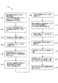
図5を参照すると、本発明の一実施形態の空気殺菌及び消毒方法500を示すフロー図が示されている。方法500は、空中の病原体を、細胞壁に浸透する既知の波長のUV放射に1秒よりも長く曝露するステップ512を含むことができる。
Referring to FIG. 5, a flow diagram illustrating an air sterilization and
より詳細には、方法500は、ステップ502において、潜在病原体を動かすために、周囲空気を、十分な環流空気交換によって、微粒子フィルタを通して空気管理室内に引き込み、ステップ504において、空気流を、空気管理室内の1つ又は複数の反応チューブ内に導く、ステップ506において、空気流をUV放射に曝露し、ステップ508において、UV放射を反応チューブ内で反射させ、ステップ510において、乱流を形成することによって空気のUV放射への曝露時間を増大させ、ステップ512において、空気流を、細胞壁に浸透する既知の波長のUV放射に1秒よりも長く曝露し、ステップ514において、空気管理室内のUVレベルを監視し、ステップ516において、空気管理室内の放射照度レベルが所望の病原体殺傷率に十分であるか否かを判断し、ステップ518において、装置が機能しているか否かをユーザに示し、ステップ520において、空気流を銅又は銅合金表面に曝露し、ステップ522において、空気流を、HEPAフィルタを通して導き、ステップ524において、空気流を、銀イオン及びクエン酸をしみ込ませた材料を通して導き、ステップ526において、清浄な衛生的な空気を周囲環境に放出して戻すことができる。
More particularly, the
上記の説明を踏まえて、本発明による実施形態を、特許請求の範囲及び趣旨内にあることが意図される多くの構成で実現することができることが認識されるべきである。さらに、上記の説明は、例示に過ぎないことが意図され、以下の特許請求の範囲に記載される以外は、本発明を限定することは決して意図されない。 In light of the above description, it should be appreciated that embodiments according to the present invention can be implemented in many configurations that are intended to be within the scope and spirit of the claims. Furthermore, the above description is intended to be illustrative only and is not intended to limit the invention in any way other than as set forth in the following claims.
Claims (19)
空気管理室からなり、該空気管理室は、
入口;
出口;
紫外線光を反射する内面と前記紫外線光を反射する内面に沿って少なくとも1つの突然拡張する領域とを備えた1つ又は複数の反応チューブ;
前記紫外線光が前記1つ又は複数の反応チューブに照射され、それによって、前記紫外線光に空気流が曝されるように配置された複数の紫外線光照射ダイオード(UV LED);
各反応チューブ内の放射照度レベルを監視するセンサ;
前記空気管理室の前記出口に位置付けられる高効率微粒子空気(HEPA)フィルタ;
前記空気管理室の前記出口に位置付けられる、銀イオン及びクエン酸を含浸させたフィルタ;
前記空気流の経路の外側に位置付けられる電子機器及び制御モジュール;
該装置が機能していることをユーザに知らせる外部可視指示手段;並びに
該装置を囲む外部ハウジング;
とを備える、空気を殺菌及び消毒する装置。 An apparatus for sterilizing and disinfecting air: germicidal and disinfecting apparatus,
Made from the air control room, the air management chamber,
entrance;
Exit;
One and a least one sudden extension area along the inner surface for reflecting inner surface and the ultraviolet light reflected ultraviolet light or a plurality of reaction tubes;
A plurality of ultraviolet light emitting diodes (UV LEDs) arranged to irradiate the one or more reaction tubes with the ultraviolet light, thereby exposing an air flow to the ultraviolet light ;
Sensors for monitoring the irradiance level in each reaction tube;
A high efficiency particulate air (HEPA) filter positioned at the outlet of the air management chamber;
A filter impregnated with silver ions and citric acid, located at the outlet of the air management chamber;
Electronics and control module positioned outside the air flow path;
An external visual indicator means to inform the user that the device is functioning; and an outer housing surrounding the device;
A device for sterilizing and disinfecting air .
Applications Claiming Priority (4)
| Application Number | Priority Date | Filing Date | Title |
|---|---|---|---|
| US201261676407P | 2012-07-27 | 2012-07-27 | |
| US13/951,598 | 2013-07-26 | ||
| US13/951,598 US8900519B2 (en) | 2012-07-27 | 2013-07-26 | Air sterilization and disinfection apparatus and method |
| PCT/US2014/048144 WO2015013586A2 (en) | 2012-07-27 | 2014-07-25 | Air sterilization and disinfection apparatus and method |
Publications (2)
| Publication Number | Publication Date |
|---|---|
| JP2016530918A JP2016530918A (en) | 2016-10-06 |
| JP6446452B2 true JP6446452B2 (en) | 2018-12-26 |
Family
ID=49995081
Family Applications (1)
| Application Number | Title | Priority Date | Filing Date |
|---|---|---|---|
| JP2016530064A Active JP6446452B2 (en) | 2012-07-27 | 2014-07-25 | Air sterilization and disinfection equipment |
Country Status (4)
| Country | Link |
|---|---|
| US (3) | US8900519B2 (en) |
| EP (1) | EP3024503B1 (en) |
| JP (1) | JP6446452B2 (en) |
| WO (1) | WO2015013586A2 (en) |
Families Citing this family (38)
| Publication number | Priority date | Publication date | Assignee | Title |
|---|---|---|---|---|
| US11000622B2 (en) * | 2012-07-27 | 2021-05-11 | Aeroclean Technologies, Llc | UV sterilization apparatus, system, and method for forced-air patient heating systems |
| US8900519B2 (en) | 2012-07-27 | 2014-12-02 | Mark D. Krosney | Air sterilization and disinfection apparatus and method |
| US9616143B2 (en) | 2013-07-17 | 2017-04-11 | Progressive Sterilization, Llc | Mobile apparatus and method for sterilizing one or more surgical trays with integrable transfer and storage system |
| WO2015092695A1 (en) | 2013-12-18 | 2015-06-25 | Koninklijke Philips N.V. | Gas delivery system and method of sanitizing the gas flow path within a gas delivery system |
| WO2015153084A1 (en) | 2014-03-10 | 2015-10-08 | Pmbs, Llc | Mobile sterilization apparatus and method for using the same |
| US9439992B2 (en) | 2014-03-10 | 2016-09-13 | Promedica, Inc. | Autoclave sterilization cabinet |
| US9511159B2 (en) | 2014-07-02 | 2016-12-06 | At&T Intellectual Property I, L.P. | Method and apparatus for sterilizing a surface |
| US9327047B1 (en) * | 2015-06-02 | 2016-05-03 | George J. Lichtblau | UVC air decontamination system |
| US10180248B2 (en) | 2015-09-02 | 2019-01-15 | ProPhotonix Limited | LED lamp with sensing capabilities |
| DE102015115713A1 (en) * | 2015-09-17 | 2017-03-23 | Hytecon Ag | Apparatus and method for the treatment of fluids |
| EP3365032B1 (en) * | 2015-10-23 | 2024-03-13 | Cleanco Bioscience Group, LLC | Uv sterilization system for forced-air patient heating systems |
| US10463759B2 (en) | 2017-01-27 | 2019-11-05 | Sterilumen, Inc. | Disinfecting vanity mirrors |
| US10039853B1 (en) | 2017-01-27 | 2018-08-07 | Sterilumen, Inc. | Hazard-free disinfectng vanity mirrors |
| US9724442B1 (en) | 2017-01-27 | 2017-08-08 | Max Munn | Disinfecting vanity mirror |
| US10086100B1 (en) | 2017-07-28 | 2018-10-02 | Pmbs, Llc | Mobile sterilization apparatus and method for using the same |
| US11406729B2 (en) | 2017-08-31 | 2022-08-09 | Aeroclean Technologies, Llc | Air treatment system and method |
| US10307504B2 (en) | 2017-09-18 | 2019-06-04 | Sterilumen, Inc. | Disinfecting apparatus device |
| KR20190090959A (en) * | 2018-01-26 | 2019-08-05 | 서울바이오시스 주식회사 | Fluid treatment device |
| BR102018006229B1 (en) * | 2018-03-27 | 2024-01-09 | Sociedade Beneficente Israelita Brasileira Hospital Albert Einstein | METHOD AND SYSTEM FOR MONITORING THE CLEANING OF HOSPITAL ENVIRONMENTS |
| CN108355897B (en) * | 2018-04-19 | 2023-11-17 | 江苏三棵白杨环保科技有限公司 | Enhanced diffusion type photocatalyst atomizer |
| DE102019116745A1 (en) * | 2019-06-20 | 2020-12-24 | Hytecon Ag | Device and method for disinfecting a fluid using UV light |
| US20210299303A1 (en) * | 2020-03-29 | 2021-09-30 | Dynamics Inc. | Uv-c virus inactivation devices and supressing sound and operating the same |
| EP3919089A1 (en) * | 2020-06-04 | 2021-12-08 | Lumileds LLC | A sterilization system having an led uv emitter and porous scattering medium |
| US11433154B2 (en) | 2020-05-18 | 2022-09-06 | Wangs Alliance Corporation | Germicidal lighting |
| US11850336B2 (en) * | 2020-05-22 | 2023-12-26 | Molekule Group, Inc. | UV sterilization apparatus, system, and method for aircraft air systems |
| US11027038B1 (en) | 2020-05-22 | 2021-06-08 | Delta T, Llc | Fan for improving air quality |
| US11672882B1 (en) | 2020-06-21 | 2023-06-13 | Proair, Llc | Air treatment system for vehicles |
| US20210402042A1 (en) * | 2020-06-30 | 2021-12-30 | Rexford Charles Johnson | Air filtration system |
| US11357882B2 (en) * | 2020-08-13 | 2022-06-14 | Tomphyzx.Llc | Method, apparatus and system for reducing pathogens in a breathable airstream in an environment |
| US11766502B2 (en) | 2020-08-13 | 2023-09-26 | Tomphyzx.Llc | Method, apparatus and system for reducing pathogens in a breathable airstream |
| JP7464275B2 (en) * | 2020-09-28 | 2024-04-09 | 宗昭 芝山 | Sterilizer set |
| DE102020126096A1 (en) | 2020-10-06 | 2022-04-07 | youvee GmbH | DEVICE FOR CLEANING ROOM AIR |
| US20220111105A1 (en) * | 2020-10-14 | 2022-04-14 | Chenghung Pan | Multifunction uv disinfecting fixture |
| US11779675B2 (en) | 2020-10-19 | 2023-10-10 | Molekule Group, Inc. | Air sterilization insert for heating, ventilation, and air conditioning (HVAC) systems |
| US11344649B1 (en) | 2020-11-12 | 2022-05-31 | Khanh Ngoc Tran | Modular contaminate capture and sterilization apparatus and method |
| US20220143260A1 (en) * | 2020-11-12 | 2022-05-12 | Dynamics Energy, LLC | Ultra-violet led device for disinfecting room air |
| DE102021106028A1 (en) | 2020-12-11 | 2022-06-15 | Dbk David + Baader Gmbh | temperature control unit |
| CN117053330B (en) * | 2023-10-11 | 2023-12-15 | 中兵长智科技有限责任公司 | Office environment monitoring and early warning device and method |
Family Cites Families (55)
| Publication number | Priority date | Publication date | Assignee | Title |
|---|---|---|---|---|
| JPH0140524Y2 (en) * | 1980-01-10 | 1989-12-04 | ||
| US5626820A (en) * | 1988-12-12 | 1997-05-06 | Kinkead; Devon A. | Clean room air filtering |
| US5225167A (en) | 1991-12-30 | 1993-07-06 | Clestra Cleanroom Technology, Inc. | Room air sterilizer |
| US6039926A (en) | 1993-11-12 | 2000-03-21 | Laurence M. Steel | Forced hot air sterilizing method and apparatus |
| US5505904A (en) | 1994-04-29 | 1996-04-09 | Jji Lighting Group, Inc. | Air disinfection unit |
| US5761908A (en) | 1994-06-10 | 1998-06-09 | Air Quality Engineering | Apparatus suited for ventilating rooms contaminated with infectious disease organisms |
| US5964792A (en) | 1996-08-02 | 1999-10-12 | Augustine Medical, Inc. | Convertible thermal blanket |
| DE19652688A1 (en) * | 1996-12-18 | 1998-06-25 | Kurt Tillmanns | Method and device for the purest filtering and disinfection of air |
| JP2000008178A (en) * | 1998-06-19 | 2000-01-11 | Sumitomo Osaka Cement Co Ltd | Metallic product provided with antibacterial property and its production |
| JP3507342B2 (en) * | 1998-08-31 | 2004-03-15 | 島田電子工業有限会社 | Water purification device and hot water pool water purification system using the same |
| JP3981477B2 (en) * | 1998-09-22 | 2007-09-26 | シンワ工業株式会社 | Equipment for decomposing organic compounds contained in fluid on piping |
| US6053968A (en) | 1998-10-14 | 2000-04-25 | Miller; Bob C. | Portable room air purifier |
| JP2000140086A (en) * | 1998-11-06 | 2000-05-23 | Ryoji Nakada | Air cleaner |
| JP2001224672A (en) * | 2000-02-18 | 2001-08-21 | Kaisei Tokushu Kogyo:Kk | Antibacterial/deodorizing processed material utilizing industrial waste, method of manufacturing the same and paving method using antibacterial/deodorizing processed material |
| WO2003039604A2 (en) * | 2001-11-02 | 2003-05-15 | Honeywell International Inc. | Ultraviolet disinfecting apparatus |
| JP2003262369A (en) * | 2002-03-07 | 2003-09-19 | Kyodo Kumiai Hanshin Seimitsu Kogyo Center | Air cleaner |
| US20030170151A1 (en) | 2002-03-08 | 2003-09-11 | Hunter Charles Eric | Biohazard treatment systems |
| JP2004108685A (en) * | 2002-09-19 | 2004-04-08 | Nippon Pmac Kk | Air conditioner with dust removing, deodorizing, and sterilizing functions |
| US6797044B2 (en) | 2002-12-03 | 2004-09-28 | Chieh Ou Yang | Air filter device |
| JP3649241B1 (en) * | 2003-03-04 | 2005-05-18 | ダイキン工業株式会社 | Air cleaning member and air conditioner |
| KR20060026404A (en) * | 2003-05-08 | 2006-03-23 | 에코-알엑스, 인코포레이티드 | System for purifying and removing contaminants from gaseous fluids |
| US7175814B2 (en) | 2003-06-16 | 2007-02-13 | Dionisio James L | Air disinfecting system and cartridge device containing ultraviolet light |
| JP3101661U (en) * | 2003-11-14 | 2004-06-17 | 有限会社エコセラム | Small disinfecting deodorizer |
| US7261730B2 (en) * | 2003-11-14 | 2007-08-28 | Lumerx, Inc. | Phototherapy device and system |
| JP2005166180A (en) * | 2003-12-03 | 2005-06-23 | Funai Electric Co Ltd | Audio/visual apparatus |
| JP4067496B2 (en) * | 2004-01-13 | 2008-03-26 | 株式会社豊振科学産業所 | Light emitting device |
| JP4033214B2 (en) * | 2004-01-14 | 2008-01-16 | 利男 川上 | Air cleaner |
| KR100508312B1 (en) * | 2004-03-02 | 2005-08-17 | 주식회사코네트인더스트리 | Air cleaner |
| JP2005253799A (en) * | 2004-03-12 | 2005-09-22 | Yoshiteru Nakasaki | Fluid purification device |
| WO2005102401A2 (en) * | 2004-04-20 | 2005-11-03 | Guido Kohler | Sterilizing device and a method for sterilizing of fluids |
| US20070196235A1 (en) | 2004-07-15 | 2007-08-23 | Michael Shur | Ultraviolet radiation-based media purification |
| US7892501B2 (en) * | 2004-07-23 | 2011-02-22 | Sharper Image Acquisition Llc | Air sanitizer |
| US20060042210A1 (en) * | 2004-08-27 | 2006-03-02 | Dallas Andrew J | Acidic impregnated filter element, and methods |
| US20070101867A1 (en) * | 2005-11-08 | 2007-05-10 | Hunter Charles E | Air sterilization apparatus |
| GB0606604D0 (en) * | 2006-04-01 | 2006-05-10 | P W Circuts Ltd | Treatment apparatus |
| JP2008259809A (en) * | 2007-03-20 | 2008-10-30 | Matsushita Electric Ind Co Ltd | Air cleaner |
| JP4858343B2 (en) * | 2007-07-20 | 2012-01-18 | 岩崎電気株式会社 | UV sterilizer |
| US20090041632A1 (en) * | 2007-08-08 | 2009-02-12 | Novapure Systems Inc. | Air Purifier System and Method |
| US8709341B2 (en) * | 2007-08-08 | 2014-04-29 | Morphic Envirotech Inc. | System for purifying air through germicidal irradiation and method of manufacture |
| US7862728B2 (en) * | 2007-09-27 | 2011-01-04 | Water Of Life, Llc. | Ultraviolet water purification system |
| JP2009106921A (en) * | 2007-10-30 | 2009-05-21 | Hiroo Mizushima | Photocatalytic filter |
| US8399028B2 (en) * | 2008-08-14 | 2013-03-19 | Exciton Technologies Inc. | Antimicrobial silver solutions |
| US8397715B2 (en) | 2008-11-28 | 2013-03-19 | Jeffrey C. Litz | Chemical and biological protection mask |
| CN102281933A (en) * | 2008-12-19 | 2011-12-14 | 北卡罗来纳大学夏洛特分校 | Systems and methods for performing the bacterial disinfection of a fluid using point radiation sources |
| JP4850273B2 (en) * | 2009-06-24 | 2012-01-11 | 晃敬 古矢 | Filter sterilizer |
| US20110033346A1 (en) | 2009-08-04 | 2011-02-10 | Bohlen Johns R | Air cleaner with photo-catalytic oxidizer |
| WO2011049140A1 (en) * | 2009-10-20 | 2011-04-28 | 株式会社フジコー | Fibrous filter and air purification device |
| WO2011087100A1 (en) * | 2010-01-15 | 2011-07-21 | 株式会社 佐多商会 | Air sterilization/purification device, and exhaled-air sterilization/purification device, indoor air sterilization/purification device, and simplified isolation device using said air sterilization/purification device |
| US20120273340A1 (en) * | 2010-12-08 | 2012-11-01 | Perry Felix | Method & apparatus for sanitizing air in aircraft, commercial airliners, military vehicles, submarines, space craft, cruise ships , passenger vehicles, mass transit and motor vehicles by integration of high density high efficiency ultra violet illumination apparatus within air conditioning, ventilation and temperature control systems |
| CN103765132A (en) * | 2011-06-01 | 2014-04-30 | 苏亚雷斯工业公司 | Portable air conditioning apparatus |
| PL395845A1 (en) * | 2011-08-02 | 2013-02-04 | Doros Teodora D. A. Glass | Method of granting bactericidal and fungicidal properties to ventilation ducts and ventilation duct to use this method |
| JP3176064U (en) * | 2012-03-26 | 2012-06-14 | 株式会社東通研 | Organic compound decomposition equipment |
| US9101904B2 (en) * | 2012-05-25 | 2015-08-11 | Honeywell International Inc. | Air purification system using ultraviolet light emitting diodes and photocatalyst-coated supports |
| US20140017135A1 (en) * | 2012-07-16 | 2014-01-16 | Mag Aerospace Industries, Inc. | Systems and Methods for Disinfecting Air On Board A Passenger Transport Vehicle |
| US8900519B2 (en) | 2012-07-27 | 2014-12-02 | Mark D. Krosney | Air sterilization and disinfection apparatus and method |
-
2013
- 2013-07-26 US US13/951,598 patent/US8900519B2/en active Active
-
2014
- 2014-07-25 EP EP14829593.4A patent/EP3024503B1/en active Active
- 2014-07-25 JP JP2016530064A patent/JP6446452B2/en active Active
- 2014-07-25 WO PCT/US2014/048144 patent/WO2015013586A2/en active Application Filing
- 2014-10-29 US US14/527,449 patent/US9480768B2/en active Active
- 2014-10-30 US US14/528,864 patent/US9974880B2/en active Active
Also Published As
| Publication number | Publication date |
|---|---|
| US8900519B2 (en) | 2014-12-02 |
| EP3024503A2 (en) | 2016-06-01 |
| EP3024503A4 (en) | 2017-03-08 |
| US9480768B2 (en) | 2016-11-01 |
| US20180050123A9 (en) | 2018-02-22 |
| WO2015013586A2 (en) | 2015-01-29 |
| EP3024503B1 (en) | 2022-09-14 |
| US20150078960A1 (en) | 2015-03-19 |
| WO2015013586A3 (en) | 2015-07-16 |
| US20160121012A1 (en) | 2016-05-05 |
| JP2016530918A (en) | 2016-10-06 |
| US9974880B2 (en) | 2018-05-22 |
| US20140030144A1 (en) | 2014-01-30 |
Similar Documents
| Publication | Publication Date | Title |
|---|---|---|
| JP6446452B2 (en) | Air sterilization and disinfection equipment | |
| US20210093744A1 (en) | UV Sterilization Apparatus, System, and Method for Forced-Air Patient Heating Systems | |
| JP6313523B2 (en) | Disinfection of rooms and regions using pulsed light with modulated power flux and optical system with visible light compensation between pulses | |
| ES2769750T3 (en) | Germicidal devices with configurations to selectively carry out different modes of disinfection inside and outside the device | |
| US20200282086A1 (en) | System and method for sterilization of fluids | |
| US20080019861A1 (en) | Air Treatment Method and Device | |
| KR102612777B1 (en) | Air treatment systems and methods | |
| KR20180061384A (en) | UV sterilization apparatus, system, and method for forced-air heating system for a patient | |
| KR20200139020A (en) | Air Cleaner Comprising Ultraviolet Air Sterilizer | |
| CN100479865C (en) | Air processing method and device | |
| KR102191577B1 (en) | Sterilization apparatus and home appliance including the same | |
| WO2019045778A1 (en) | Uv sterilization apparatus, system, and method for forced-air patient heating systems | |
| JP2023544252A (en) | Integrated air sterilizer and surface sterilizer | |
| KR20220039766A (en) | Cold air treatment device, method of applying cooled air flow, and use of air disinfection device | |
| US11369712B1 (en) | Baffles for modifying airflow in UV air sterilization device | |
| US11779675B2 (en) | Air sterilization insert for heating, ventilation, and air conditioning (HVAC) systems | |
| KR20220162500A (en) | Air sterilization device | |
| KR20200135920A (en) | Sterilization apparatus and home appliance including the same | |
| RU22346U1 (en) | DEVICE FOR DISINFECTING AIR |
Legal Events
| Date | Code | Title | Description |
|---|---|---|---|
| A521 | Request for written amendment filed |
Free format text: JAPANESE INTERMEDIATE CODE: A523 Effective date: 20160729 |
|
| A521 | Request for written amendment filed |
Free format text: JAPANESE INTERMEDIATE CODE: A523 Effective date: 20160809 |
|
| A621 | Written request for application examination |
Free format text: JAPANESE INTERMEDIATE CODE: A621 Effective date: 20170707 |
|
| A977 | Report on retrieval |
Free format text: JAPANESE INTERMEDIATE CODE: A971007 Effective date: 20180523 |
|
| A131 | Notification of reasons for refusal |
Free format text: JAPANESE INTERMEDIATE CODE: A131 Effective date: 20180531 |
|
| A601 | Written request for extension of time |
Free format text: JAPANESE INTERMEDIATE CODE: A601 Effective date: 20180828 |
|
| A521 | Request for written amendment filed |
Free format text: JAPANESE INTERMEDIATE CODE: A523 Effective date: 20180906 |
|
| TRDD | Decision of grant or rejection written | ||
| A01 | Written decision to grant a patent or to grant a registration (utility model) |
Free format text: JAPANESE INTERMEDIATE CODE: A01 Effective date: 20181101 |
|
| A61 | First payment of annual fees (during grant procedure) |
Free format text: JAPANESE INTERMEDIATE CODE: A61 Effective date: 20181203 |
|
| R150 | Certificate of patent or registration of utility model |
Ref document number: 6446452 Country of ref document: JP Free format text: JAPANESE INTERMEDIATE CODE: R150 |
|
| R250 | Receipt of annual fees |
Free format text: JAPANESE INTERMEDIATE CODE: R250 |
|
| R250 | Receipt of annual fees |
Free format text: JAPANESE INTERMEDIATE CODE: R250 |
|
| R250 | Receipt of annual fees |
Free format text: JAPANESE INTERMEDIATE CODE: R250 |