JP6446236B2 - Vehicle control system - Google Patents
Vehicle control system Download PDFInfo
- Publication number
- JP6446236B2 JP6446236B2 JP2014219960A JP2014219960A JP6446236B2 JP 6446236 B2 JP6446236 B2 JP 6446236B2 JP 2014219960 A JP2014219960 A JP 2014219960A JP 2014219960 A JP2014219960 A JP 2014219960A JP 6446236 B2 JP6446236 B2 JP 6446236B2
- Authority
- JP
- Japan
- Prior art keywords
- sat
- server
- data
- control system
- sensor
- Prior art date
- Legal status (The legal status is an assumption and is not a legal conclusion. Google has not performed a legal analysis and makes no representation as to the accuracy of the status listed.)
- Expired - Fee Related
Links
Images


Classifications
-
- B—PERFORMING OPERATIONS; TRANSPORTING
- B60—VEHICLES IN GENERAL
- B60R—VEHICLES, VEHICLE FITTINGS, OR VEHICLE PARTS, NOT OTHERWISE PROVIDED FOR
- B60R16/00—Electric or fluid circuits specially adapted for vehicles and not otherwise provided for; Arrangement of elements of electric or fluid circuits specially adapted for vehicles and not otherwise provided for
- B60R16/02—Electric or fluid circuits specially adapted for vehicles and not otherwise provided for; Arrangement of elements of electric or fluid circuits specially adapted for vehicles and not otherwise provided for electric constitutive elements
- B60R16/023—Electric or fluid circuits specially adapted for vehicles and not otherwise provided for; Arrangement of elements of electric or fluid circuits specially adapted for vehicles and not otherwise provided for electric constitutive elements for transmission of signals between vehicle parts or subsystems
- B60R16/0231—Circuits relating to the driving or the functioning of the vehicle
Landscapes
- Engineering & Computer Science (AREA)
- Automation & Control Theory (AREA)
- Mechanical Engineering (AREA)
- Programmable Controllers (AREA)
- Small-Scale Networks (AREA)
Description
本発明は、車両制御システムに関し、より具体的には、複数のセンサおよび複数のアクチュエータを有する車両制御システムに関する。 The present invention relates to a vehicle control system, and more specifically to a vehicle control system having a plurality of sensors and a plurality of actuators.
車両、特に自動推進車両は、一般的に、車両全体にわたって、数百とまではいかないものの数十のセンサを含み、それらはそれぞれ、ある条件を表す出力信号を生成する。例えば、かかる車両センサとしては、エンジン温度センサ、加速ペダル位置センサ、ドア開放センサ、ブレーキペダル位置センサなどが挙げられる。 Vehicles, particularly self-propelled vehicles, typically include dozens, if not hundreds, of sensors throughout the vehicle, each producing an output signal that represents a condition. For example, such vehicle sensors include an engine temperature sensor, an accelerator pedal position sensor , a door opening sensor, a brake pedal position sensor, and the like.
それに加えて、現代の自動推進車両は、車両全体にわたって分配された複数のアクチュエータも含む。これらのアクチュエータは、一般に、車両の動作を制御する。例えば、あるアクチュエータはエンジンのスロットル位置を制御するのに使用されてもよく、別のアクチュエータは車両ブレーキを作動させるのに使用されてもよく、その他も考えられる。 In addition, modern self-propelled vehicles also include a plurality of actuators distributed throughout the vehicle. These actuators generally control the operation of the vehicle. For example, one actuator may be used to control the throttle position of the engine, another actuator may be used to actuate the vehicle brake, and others are contemplated.
車両制御システムでは、プログラミングしたプロセッサを包含するECUが、各センサならびに各アクチュエータと関連付けられたセンサと関連付けられた各ECUの場合、ECUは、その関連したセンサから入力信号を受信し、そのセンサ値を処理し、次に、1つまたは複数のアクチュエータに対する出力値を生成して、車両の動作を制御する。同様に、各アクチュエータと関連付けられたECUもまた、受信したセンサ入力の関数として、それに関連したアクチュエータの目標位置を決定する、プログラミングしたプロセッサを包含する。そのECUは、次に、それらの入力を処理して、それに関連したアクチュエータの新しい目標位置を決定し、次に、アクチュエータに対する出力信号を生成して、その目標値を達成する。 In a vehicle control system, if the ECU containing the programmed processor is each ECU associated with each sensor as well as the sensor associated with each actuator, the ECU receives an input signal from the associated sensor and detects its sensor value. And then generating output values for one or more actuators to control the operation of the vehicle. Similarly, the ECU associated with each actuator also includes a programmed processor that determines the target position of the associated actuator as a function of the received sensor input. The ECU then processes those inputs to determine a new target position for the actuator associated therewith, and then generates an output signal for the actuator to achieve the target value.
自動推進車両における様々なECU間の通信を可能にするために、CANバスなどのワイヤバスが自動推進車両全体を通して延在し、センサおよびアクチュエータ用のECUを共に相互接続している。しかしながら、CANバスは、ECU間の信号の処理は行わず、それどころか、ECUを共に電気的に接続しているだけである。センサおよびアクチュエータに関するすべての処理は、それらのセンサおよびそれらのアクチュエータと関連付けられたECUによって行われる。 In order to allow communication between various ECUs in an autopropelled vehicle, a wire bus such as a CAN bus extends through the entire autopropelled vehicle and interconnects the ECUs for sensors and actuators together. However, the CAN bus does not process signals between the ECUs, but rather only electrically connects the ECUs together. All processing for sensors and actuators is performed by the ECUs associated with those sensors and their actuators.
これらの車両制御システムはすべて、多数の共通した不利な点を有する。これまでに知られている車両制御システムの1つの不利な点は、各センサおよび各アクチュエータと関連付けられたECUが、かなり高価なマイクロプロセッサコントローラチップ、ならびに特注の特定用途向け集積回路(ASIC)を包含し、それらが共に、車両の総コストに大幅に影響している点である。 All these vehicle control systems have a number of common disadvantages. One disadvantage of previously known vehicle control systems is that the ECU associated with each sensor and each actuator has a fairly expensive microprocessor controller chip, as well as a custom application specific integrated circuit (ASIC). Both of which have a significant impact on the total cost of the vehicle.
これらの車両制御システムの別のさらなる不利な点は、各ECUに包含されるマイクロプロセッサを別々にプログラミングしなければならない点である。さらに、任意の特定のECUを再プログラミングするには、ECUを完全に再設計するしかない場合が多い。これは当然ながら、高価であり、車両の総コストが増加する。 Another further disadvantage of these vehicle control systems is that the microprocessors included in each ECU must be programmed separately. Furthermore, reprogramming any particular ECU often involves a complete redesign of the ECU. This is of course expensive and increases the total cost of the vehicle.
車両制御システムの別のさらなる不利な点は、センサおよびアクチュエータ用のECUが、車両全体を通して延在する電気的バスによって共に配線接続される点である。ECUの数が増加するにつれて、コントローラエリアネットワーク(CAN)が必要とする配線の数および量が劇的に増加してきた。このことは、少なくとも3つの理由で不利である。 Another further disadvantage of the vehicle control system is that the ECUs for the sensors and actuators are wired together by an electrical bus that extends throughout the vehicle. As the number of ECUs has increased, the number and amount of wiring required by the controller area network (CAN) has increased dramatically. This is disadvantageous for at least three reasons.
第一に、ECUを共に接続する配線の量が増加するにつれて、コントローラエリアネットワークを完成させるためのワイヤおよびそのコネクタの実際のコストが増大する。これによって車両の総コストが増加する。 First, as the amount of wiring connecting the ECUs together increases, the actual cost of the wires and their connectors to complete the controller area network increases. This increases the total cost of the vehicle.
第二に、ECUを共に接続するのにCANが必要とする配線の量が増加するにつれて、
CANが必要とする配線をすべて組み立てるための車両の組立てコストも増加する。これによっても車両の総コストが増加する。
Second, as the amount of wiring required by CAN to connect the ECUs together increases,
The assembly cost of the vehicle for assembling all the wiring required by the CAN also increases. This also increases the total cost of the vehicle.
次に、ECUを共に相互接続する配線全体の複雑さが増加するにつれて、電気雑音および電磁適合性(EMC)も増加する。かかる電気雑音は、例えば、車両内に収容されたインフォテインメント機器の動作に干渉するだけでなく、深刻な場合、車両の実際の動作にも干渉する可能性がある。 Second, as the complexity of the overall wiring interconnecting the ECUs increases, the electrical noise and electromagnetic compatibility (EMC) also increases. Such electrical noise, for example, not only interferes with the operation of infotainment equipment housed in the vehicle, but in serious cases it can also interfere with the actual operation of the vehicle.
最後に、CANネットワークからの配線の量が増加するにつれて、車両の総重量に対す
るCANネットワークの実際の重量寄与分も増加する。このことは、ひいては、車両の性能を不利に低下させ、燃料消費量を増加させる。
Finally, as the amount of wiring from the CAN network increases, the actual weight contribution of the CAN network to the total weight of the vehicle also increases. This, in turn, disadvantageously reduces vehicle performance and increases fuel consumption.
本発明は、システムにおける上述の不利な点をすべて克服する車両制御システムを提供する。 The present invention provides a vehicle control system that overcomes all of the above disadvantages in the system.
概して、車両制御システムの各ECUは、ECUがアクチュエータと、もしくはセンサと、またはそれら両方のいずれと関連付けられるかに係わらず、低コストCPUを有する低コストのセンサ/アクチュエータ送受信機(sensor-actuator-transceiver)(SAT)と置き換えられる。低コストCPUは、単に、センサからの受信データを処理し、送信されるデータを生成する。SAT全体がCPUと併せて標準化されてもよく、即ち、CPUに対するプログラミングが異なるとしても、同じSATが、車両全体にわたって異なるセンサおよび異なるアクチュエータに使用されてもよい。 In general, each ECU in a vehicle control system has a low-cost sensor / actuator transceiver with a low-cost CPU, regardless of whether the ECU is associated with an actuator, a sensor, or both. transceiver) (SAT) The low-cost CPU simply processes the data received from the sensor and generates the data to be transmitted. The entire SAT may be standardized in conjunction with the CPU, i.e., the same SAT may be used for different sensors and different actuators throughout the vehicle, even though the programming for the CPU is different.
各SATは、1バイトなどの固有の識別情報を有する。それに加えて、各SATは、ブルートゥース(登録商標)、IPv4などの任意の標準プロトコルを使用して、送信機を通して無線でそのデータ値を受信ならびに通信する。 Each SAT has unique identification information such as 1 byte. In addition, each SAT is Bluetooth (registered trademark), using any standard protocols such as IPv4, receives and communicates the data values by radio through the transmitter.
しかしながら、ECUとは異なり、SATは、受信または送信されたデータを処理して、任意の値を決定することはしない。それよりもむしろ、センサと関連付けられたSATは単に、そのセンサ値を表すデータを送信し、アクチュエータと関連付けられたSATは単に、それに関連したアクチュエータの目標値を示すデータを受信する。 However, unlike the ECU, the SAT does not process received or transmitted data to determine an arbitrary value. Instead, the SAT associated with the sensor simply transmits data representing the sensor value, and the SAT associated with the actuator simply receives data indicating the actuator target value associated therewith.
各SATに対してCPUの埋込みソフトウェアのアプリケーション層を実装するために、高性能サーバが車両内に収容される。この高性能サーバは、サーバ内で実行されるソフトウェア・イン・ザ・ループ・シミュレーション(SILS)として、各センサおよびアクチュエータに対する制御ソフトウェアを実装する。好ましくは、車両内の各SATには、サーバによって実行されるシミュレーションソフトウェアが同時に実行されても良いように、予め定められた分割されたデータ領域がサーバによって割り当てられる。 A high performance server is housed in the vehicle to implement the CPU embedded software application layer for each SAT. This high performance server implements the control software for each sensor and actuator as software in the loop simulation (SILS) executed in the server. Preferably, a predetermined divided data area is assigned to each SAT in the vehicle by the server so that simulation software executed by the server may be executed simultaneously.
様々なSATと通信するために、サーバは、データだけでなく目標SATの識別情報も包含するデータパケットを作成する。次に、SATは、データパケット形式で、ゲートウェイを通してサーバにデータを送信する。 In order to communicate with the various SATs, the server creates data packets that contain not only the data but also the identification information of the target SAT. The SAT then sends data to the server through the gateway in the form of a data packet.
サーバによって様々な分割されたデータ領域で実行されるSILSは、それらと関連したSATと無線で直接通信するが、状況によっては、1つのSILSが異なるまたは複数のSATと通信することが必要である。これを遂行するために、サーバによって実行されるSILSマネージャは、様々なSILS間の通信を確立すると共に、SILSが他のSILSと通信し、それらが次いで、車両全体にわたる別のSATと通信するのを可能にする。 SILS executed in various partitioned data areas by the server communicate directly over the air with the SAT associated with them, but in some situations it is necessary for one SILS to communicate with different or multiple SATs . To accomplish this, the SILS manager executed by the server establishes communication between the various SILS, and the SILS communicates with other SILS, which in turn communicate with another SAT across the vehicle. Enable.
本発明の車両制御システムの主要な利点は、車両内の各センサおよびアクチュエータと関連付けられた複雑なECUが、車両全体にわたる低コストSAT、ならびにデータを処理しSATと通信する単一の高性能サーバに置き換えられる点である。このことにより、ひいては、車両制御システムの総コストが低下する。 A major advantage of the vehicle control system of the present invention is that a complex ECU associated with each sensor and actuator in the vehicle provides a low cost SAT across the vehicle, as well as a single high performance server that processes data and communicates with the SAT. It is a point that can be replaced. This eventually reduces the total cost of the vehicle control system.
それに加えて、サーバはSATと無線で通信するので、配線接続CANシステムのワイヤコスト、設置コスト、および複雑さが排除される。同様に、別の方法ではCANシステムによって起こり得る、EMCおよび電気雑音も排除される。 In addition, because the server communicates wirelessly with the SAT, the wire cost, installation cost, and complexity of the wire-connected CAN system is eliminated. Similarly, EMC and electrical noise that could otherwise be caused by the CAN system are also eliminated.
さらに、車両毎に、または車両の年式毎にSATを再プログラミングする場合、そのセンサと関連付けられたSATに対する修正を要しない。より正確に言えば、必要とされることがある唯一の修正は、サーバに包含されるSILSソフトウェアの修正である。サーバソフトウェアはC++などの高水準言語でプログラミングされるので、SATの任意の1つまたは複数のためのSILSソフトウェアにおけるソフトウェア修正は、簡単かつ迅速に遂行されてもよい。 Furthermore, if the SAT is reprogrammed on a vehicle-by-vehicle or vehicle-by-year basis, no modifications to the SAT associated with that sensor are required. More precisely, the only modification that may be required is a modification of the SILS software that is included in the server. Since the server software is programmed in a high level language such as C ++, software modifications in SILS software for any one or more of the SATs may be performed simply and quickly.
以下の詳細な説明を添付図面と併せて参照することにより、本発明についてのより十分な理解が得られるであろう。複数の図面を通して、同様の参照符号は同様の部分を指す。 A more complete understanding of the present invention may be obtained by reference to the following detailed description in conjunction with the accompanying drawings. Like reference numerals refer to like parts throughout the several views.
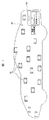
図1を参照すると、車両制御システムを備えた例示的な車両30が示される。多くの現代の自動推進車両のように、この自動推進車両は、車両全体にわたって複数のセンサおよびアクチュエータを含む。
Referring to FIG. 1, an
センサ/アクチュエータ送受信機(SAT)32は、車両全体にわたって各ECUと関連付けられる。実際には、1つのSAT32が、1つまたは複数のセンサならびに1つまたは複数のアクチュエータと関連付けられてもよい。あるいは、特定のSAT32が、単一のセンサまたは単一のアクチュエータのみと関連付けられてもよい。
A sensor / actuator transceiver (SAT) 32 is associated with each ECU throughout the vehicle. In practice, one
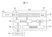
次に図2を参照すると、1つのSAT32の概略図が示される。図2に示されるSAT32は、1つのセンサ34および/または1つのアクチュエータ36と関連付けられている。しかしながら、追加のセンサ34ならびに追加のアクチュエータ36も各SAT32と関連付けられても良い。同様に、SAT32は、単一のセンサ34または単一のアクチュエータ36のみと関連付けられているが、2つ以上のセンサ34またはアクチュエータ36と関連付けることができても良い。
Referring now to FIG. 2, a schematic diagram of one
SAT32は、読出し専用メモリ(ROM)40が包含するコンピュータプログラムによってプログラミングされる、PICなどの低コストCPU38を含む。CPU38はまた、ROM40が包含するプログラムによって要求される変数を一時的に格納するため、ランダムアクセスメモリ(RAM)42に対するアクセスを有する。
The
さらに図2を参照すると、SAT32はまた、入出力回路44を通してセンサ34と通信し、同様に、入出力回路46を通してアクチュエータ36と通信する。SAT32は、無線送信プロトコルを通してデータの送受信両方を行うSAT側の無線送受信機48を包含する。
Still referring to FIG. 2,
車両制御システムのECUとは異なり、SAT32は、車両の動作を制御するのに使用される最適値または目標値を決定するため、SAT32と関連付けられたそのセンサ34またはアクチュエータ36から受信するデータを処理することはしない。より正確に言えば、SAT32の唯一の機能は、特定のパラメータを、例えばエンジンオイル温度、エンジン回転数、空気圧などを測定し、SAT側の無線送受信機48によって後で送信されるSATデータパケットを作成するか、またはアクチュエータ36の目標値を表す、ひいてはその関連したアクチュエータ36をその目標値へと移動させる、データパケットを受信することである。
Unlike the vehicle control system ECU, the
いくつかの例示的なSATデータパケットが図3に示される。例えば、アクセルペダルと関連付けられたSAT32に対する1つのSATデータパケット50が示される。エンジン回転数センサと関連付けられたSAT32に対する更なるSATデータパケット52が示され、タイヤ空気圧と関連付けられたSAT32に対するSATデータパケット54が示される。最後に、この例では、ハイブリッド車両向けのモータ制御に対するSATデータパケット56が示される。
Some exemplary SAT data packets are shown in FIG. For example, one
さらに図3を参照すると、SATデータパケット50〜56はそれぞれ、各SATデータパケットのヘッダとして、少なくとも1データバイトを、好ましくは数データバイトを含む。0xAB 0xBA 0xAB 0xBAとして図3に示されるヘッダ値は、各データパケット50〜56に関して同じである。実際には、ヘッダバイト58を含むことは単に、ヘッダバイト58に続くデータがあることの指示である。
Still referring to FIG. 3, each SAT data packet 50-56 includes at least one data byte, preferably several data bytes, as the header of each SAT data packet. The header values shown in FIG. 3 as 0xAB 0xBA 0xAB 0xBA are the same for each data packet 50-56. In practice, including the
ヘッダバイトの後、SAT IDバイト60が各データパケット50において送られる。各SAT32をSAT IDバイト60によって識別できるように、SAT IDバイト60は、車両に収容された各SAT32に対して固有のものである。SAT ID60によって、SAT32の無線送受信機48がその特定のSAT32に送られたメッセージのみを受信し処理することができるだけでなく、送受信機48が、SAT32による送信メッセージをSAT IDバイト60を用いて符号化することが可能になる。
After the header byte, a
SAT IDバイト60に続いて、1つまたは複数のデータバイト62は、様々なSAT32に送信された、またはそれらによって受信された実データを表す。実データは2バイトであってもよく、特定のSAT32に対して適切なデータを包含する。
Following the
最後に、データパケット50〜56はそれぞれ、好ましくはチェックサムバイト64で終わる。チェックサムバイト64は、データパケット中の他のバイトに応じて変わる。チェックサムバイト64は、データパケットごとに変わり、送受信されたデータが有効であって破損していないことを検証するメカニズムを提供する。
Finally, each data packet 50-56 preferably ends with a
次に図4を参照すると、SAT32によるデータパケットの構築を示すフローチャートが示される。ステップ66でSAT32を始動した後、ステップ66はステップ68に進む。ステップ68で、低コストのCPU38(図2)は、センサ34に対する測定プロセスが完了していることを示す適切なトリガを待機する。完了すると、ステップ68はステップ70に進む。
Referring now to FIG. 4, a flowchart illustrating the construction of a data packet according to
ステップ70で、CPU38は、センサ34またはアクチュエータ36のデフォルトのヘッダ値をROM40から読み出す。次に、ステップ70はステップ72に進み、ヘッダデータ(図3)をRAM42が包含するデータレジスタにコピーする。次に、ステップ72はステップ74に進む。
In
ステップ74で、CPU38は、SAT IDバイト60の値をROM40から読み出し、次にステップ76に進み、SAT IDバイト60の値をRAM42のデータレジスタが包含するヘッダバイトの値に付加する。次に、ステップ76はステップ78に進む。
In
ステップ78で、センサ/アクチュエータデータを、RAM42が包含するアナログ/デジタルメモリレジスタから読み出す。次に、ステップ78はステップ80に進み、センサ/アクチュエータからのデータ測定値を、SAT IDバイト60の後に、RAM42が包含するデータレジスタに付加する。次に、ステップ80はステップ82に進む。ステップ82で、ヘッダバイト58、SAT IDバイト60、およびデータバイト62を使用して、チェックサムを計算する。次に、ステップ82はステップ84に進み、チェックサムを、RAM42が包含するデータレジスタのデータバイト62の後に付加する。好ましくは、IPv4などの標準伝送プロトコルを使用して、SAT側の無線送受信機48との間でメッセージが送信される。車両30内のすべてのSAT32に対するIPアドレスは同一であってもよく、例えば車両30のVIN番号であってもよいが、あるいは、IPアドレスは動的に割り当てられてもよく、異なるSAT32に対して異なってもよい。この方法では、隣接車両などの他のソースから受信したメッセージは無視され、同じ車両30内のサーバ側の無線送受信機108(図5)とSAT32との間の安全な通信が保証されてもよい。
In
したがって、ステップ86で、SAT IDバイト60を含むステップ84からのSATデータパケットを、RAM42が包含するデータレジスタ内のIPv4パケットデータフィールドに付加する。SAT32のすべてのデータは、伝送プロトコルにおいてカプセル化されるので、SAT IDバイト60が、IP(インターネットプロトコル)の送信先/送信元アドレスとは異なる各SAT32を識別するのに使用される。いずれの場合も、チェックサムの計算および付加の後には、RAM42のデータレジスタ内のデータは、SAT側の無線送受信機48によって送信できる状態になっている。次に、ステップ86はステップ68に戻って、上述のプロセスが繰り返される。
Accordingly, at
図1および5を参照すると、SAT32はすべて、車両のトランク内など、車両30の任意の適切な場所に収容されたサーバ100と通信する。サーバ100は、データを同時に処理することができるいくつかのコアを好ましくは利用する、高性能コンピュータサーバである。
With reference to FIGS. 1 and 5, all SATs 32 communicate with a
サーバ100は、サーバ100の動作全体を制御する、オペレーティングシステム102のソフトウェア層を含む。サーバは、サーバ100内のSILSマネージャ104のソフトウェアレベルを通して、各SAT32に対してソフトウェア・イン・ザ・ループ・シミュレーション(SILS)を実行する。好ましくは、SAT32それぞれに対するSILS106は、分割された異なるデータ領域内に配置される。その結果、SILSマネージャ104によって、1つのSAT32からの値が必要に応じてシステムの他のSAT32に対するSILS106に提供されても良いように、分割されたSILS106が互いに通信することが可能になる。好ましくは、サーバ100は、様々なSILS106に対する同時計算を可能にする、プログラミングされたマルチコアプロセッサを利用する。
次に、サーバ100は、ブルートゥース(登録商標)、IPv4などの標準プロトコルを使用して、サーバ側の無線送受信機108を通して様々なSAT32と通信する。この方法では、サーバ100は、SAT32から値を受信できるだけでなく、例えば、車両30に収容された様々なアクチュエータ36の目標位置を変更するのに必要な値を、SAT32に対して返送することができる。
Next, the
次に図6を参照すると、SAT32と関連付けられたセンサ34から値を取得する、CPU38のSATプロセッサのためのフローチャートが示される。ステップ120で始動した後、ステップ120はステップ122に進む。
Referring now to FIG. 6, a flowchart for the SAT processor of the
ステップ122で、CPU38のSATプロセッサ(図2)は、ユーザアクションからのトリガ、またはサーバ側の無線送受信機108(図5)からの呼掛けを待機する。トリガまたは呼掛けを受信した後、ステップ122はステップ124に進む。
In
ステップ124で、CPU38のSATプロセッサは、SAT32と関連付けられたセンサパラメータを測定または更新する。次に、ステップ124はステップ126に進み、CPU38のSATプロセッサが、その関連したセンサ34からのアナログ信号のアナログ/デジタル変換を行う。CPU38のSATプロセッサはまた、必要であればスケーリングを行い、次にステップ128に進む。
At
複数のセンサが単一のSAT32と関連付けられてもよい。したがって、ステップ128で、CPU38のSATプロセッサは、センサ値がすべて測定または更新されているかを判断する。該当しない場合、ステップ128はステップ124に戻って、SAT32と関連付けられた各センサに対して上述のプロセスを繰り返す。SAT32と関連付けられたセンサがすべて測定されたら、ステップ128はステップ130に進む。
Multiple sensors may be associated with a
ステップ130で、プロセッサは、図4に示した上述のフローチャートにしたがって、
SATデータパケットを準備する。SATデータパケットが形成された後、ステップ130はステップ132に進み、SATデータパケットを、SAT32と関連付けられたSAT側の無線送受信機48によって送信する。次に、ステップ132はステップ122に戻り、上述のプロセスを繰り返す。
In
Prepare a SAT data packet. After the SAT data packet is formed,
SATによるデータ取得およびその後の送信を開始する実際のトリガは、どのセンサがSAT32と関連付けられるかに応じて変わる。例えば、加速ペダルの移動、ダッシュボードのファンクションキーの押下げ、制動などはすべてトリガを構成し、それによって最終的に、IPv4メッセージ内に好ましくはカプセル化されたSATデータパケットが、SAT32の無線送受信機からサーバ100の無線送受信機108へと送信される。
The actual trigger that initiates data acquisition and subsequent transmission by the SAT varies depending on which sensor is associated with the
SATデータパケットをSAT32から受信すると、その特定のSAT32と関連付けられたサーバ100内のSILSソフトウェアは、データを処理すると共に制御信号を生成し、その制御信号が、IPv4メッセージ内に好ましくはカプセル化されたSATパケットとして、そのSAT32に返送されるかまたは他のSAT32に送信される。SATデータパケットがSAT32の無線送受信機48によって受信されると、CPU38のSATプロセッサは受信データを処理し、入出力回路46を通してアクチュエータ36に至る適切な信号を生成して、アクチュエータ36を目標値へと移動させる。
Upon receiving a SAT data packet from
次に図7を参照すると、SAT32によるサーバからの受信信号の処理を示すフローチャートが示される。ステップ140でCPU38のSATプロセッサのためのソフトウェアを始動した後、ステップ140はステップ142に進む。ステップ142で、CPU38のSATプロセッサのためのソフトウェアは、サーバ100からの信号またはデータパケット送信を受信するのを待機する。サーバ100からのデータパケット送信を受信すると、ステップ142はステップ144に進む。
Next, referring to FIG. 7, a flowchart showing processing of a received signal from the server by the
ステップ144で、CPU38のSATプロセッサは受信したデータパケットを検査し、SAT32の受信SAT IDバイト60(図3)を比較して、受信SAT IDバイト60がSAT32に割り当てられたSAT IDバイト60と一致するかを判断する。一致しない場合、ステップ144はステップ146に進み、サーバ側の無線送受信機108からの次の送信を待機する。反対に、受信SAT IDバイト60がSAT32に割り当てられたSAT IDバイト60と一致する場合、ステップ144はその代わりにステップ148に進む。
In
ステッ148で、CPU38のSATプロセッサは受信したSATデータパケットを復号化する。ステップ148におけるSATデータパケットのかかる復号化は、データバイト62の抽出だけでなく、チェックサムバイト64を計算しそれと比較して、受信データが破損していないことを担保することも含む。次に、ステップ148はステップ150に進み、データバイト62をデータパケットから抽出する。ステップ150はステップ152に進み、デジタル/アナログ変換、および必要に応じてスケーリングを、CPU38のSATプロセッサによって行う。D/A変換およびスケーリングの後、アクチュエータ36に対する適切な作動信号を作成する。次に、ステップ152はステップ154に進み、CPU38のSATプロセッサが入出力回路46を通して適切な出力信号を生成して、アクチュエータ36を目標値へと移動させる。次に、ステップ154はステップ146に進み、サーバ側の無線送受信機108からの次の信号生成を待機する。
In
複数のECUを利用してセンサ出力を処理し、アクチュエータ36に対する目標値を計算し、次にそれらアクチュエータの作動を制御する車両制御システムとは異なり、ECUに代わるSATは単に、2つの基本機能のみを行う下位層ハードウェアドライバソフトウェアを実行する。第一に、下位層SATソフトウェアは、センサ34からの測定値をデータとして受信し、そのデータをSATデータパケット内にパッケージ化し、次にそのデータパケットをサーバ100に送信する。第二に、SATプロセッサは、アクチュエータ36に対するSATデータパケットをサーバから受信し、アクチュエータに対する目標値を包含するデータパケットを復号化し、次に、アクチュエータ36の位置を制御するために、適切なデータ信号を、即ち可変電圧、PWM、または他の信号を、アクチュエータ36に対して出力する。しかしながら、ECUを使用する車両制御システムとは異なり、SAT32は、アクチュエータ36に対する目標値を決定するためのデータ処理は行わない。同様に、SAT32は、CANネットワークなどのネットワークを通して互いに直接通信しない。より正確に言えば、各SATは単に、好ましくは無線送信によってサーバ100と通信する。
Unlike vehicle control systems that use multiple ECUs to process sensor outputs, calculate target values for
反対に、サーバ100は、SATから受信したデータに対するデータ処理をすべて行って、車両のアクチュエータ36に対する目標値を決定する。アプリケーションソフトウェアのこの上位層は、各SAT32に異なるデータ領域が分割して割り当てられたSILS環境で行われて、その特定のSAT32に対する入力および出力データが処理される。SILS106の実際のプログラミングは、C++などの高水準言語で行われる。
Conversely, the
次に図8を参照すると、1つのSILS106とその関連したSAT32との間のインターフェースのブロック図が示される。1つのSILS106が車両内の異なるSAT32それぞれと関連付けられる。
Referring now to FIG. 8, a block diagram of an interface between one
SILS106は、CまたはC++などの高水準言語で記述されたアプリケーションソフトウェア162を含む。アプリケーションソフトウェア162は、好ましくは、サーバ100によって分配されたそれ自体の分割されたデータ領域に包含され、SAT32に対する入力および出力データの必要な処理の複雑さに応じてサイズが変動する。このアプリケーションソフトウェア162は、更に、サーバ100のオペレーティングシステムの制御下で、アプリケーション層でのみ動作する。アプリケーションソフトウェア162は、デバイスドライバなどの下位レベルのソフトウェア処理を含まない。アプリケーションソフトウェア162は、SAT32から受信した入力データまたはセンサデータの両方を処理し、サーバ100の無線送受信機108によってSAT32に送信される制御データを生成する。
アプリケーションソフトウェア162は、入出力ゲートウェイモデル164を通して、その関連したSAT32と通信する。次に、入出力ゲートウェイモデル164は、サーバ100内の無線送受信機108を通して、その関連付けられたSAT32と通信する。
次に図5および図9を参照すると、SILSマネージャ104は、サーバ100のオペレーティングシステム102の制御下で動作して、SILS[0]〜SILS[N]間の通信を制御する([0]〜[N]はSILSに付された連続番号で、車両に収容されたSAT32の数に等しい)。SILSマネージャ104を始動するために、ステップ170でサーバを始動した後、ステップ170はステップ172に進み、イグニッションスイッチがオンであるかを判断する。オンでない場合、ステップ172はステップ178で終わる。
Next, referring to FIG . 5 and FIG. 9, the
反対に、イグニッションスイッチがオンである場合、ステップ172はステップ174に進み、サーバ側の無線送受信機108のためのハードウェアを初期化する。次に、ステップ174はステップ176に進み、サーバ100のオペレーティングシステム102を始動するかまたは立ち上げ、また、連成シミュレーション(co-simulation)ツール178(図5)を起動する。この連成シミュレーションツール178によって、SILS[0]〜SILS[N]が互いに通信することができる。次に、ステップ176はステップ180に進む。ステップ180で、SILSマネージャ104を起動し、SILS[0]〜SILS[N]がすべて始動される。ステップ180におけるSILSマネージャ104およびSILS106の始動に続いて、サーバ100を完全に初期化する。
Conversely, if the ignition switch is on,
次に図10を参照すると、ステップ180(図9)におけるSILSマネージャ104の始動後の、SILSマネージャ104の動作を示すフローチャートが示される。ステップ182におけるSILSマネージャ104の始動後、ステップ182はステップ184に進み、イグニッションスイッチがオンであるかを判断する。オンでない場合、ステップ184はステップ186に分岐し終了する。オンである場合、ステップ184はステップ188に進む。
Referring now to FIG. 10, a flowchart illustrating the operation of the
ステップ188で、SILSマネージャ104は、SAT(n)からのトリガユーザアクションを待機する(n=(0)〜(N)はSATに付された連続番号で、SAT32の数に等しい)。トリガアクションを受信すると、ステップ188はステップ190に進み、データパケットを復号化してSAT IDバイト60を決定し、復号化されたSAT IDバイト60から、SATデータパケットを送信したSAT(n)を識別する。次に、ステップ190はステップ192に進む。
In
ステップ192で、SILSマネージャ104は、データパケット50〜56(図3)の残りを復号化し、ステップ190で識別されたSILS IDバイトと関連付けられたSILS106のソフトウェアを起動する。ステップ192はまた、データバイト62および他のデータペイロードを、SAT32と関連付けられた、起動したSILS106に転送する。次に、ステップ192はステップ194に進む。
At
ステップ194で、SILSマネージャ104は、SILS106がSAT(n)から受信したデータパケットの処理を完了していることを示す、SILS106からのトリガを待機する。次に、ステップ194はステップ196に進み、SILSマネージャ104が、ステップ194で受信した出力またはデータペイロードを処理するSILSソフトウェアを実行する。次に、ステップ196はステップ198に進み、処理したデータをデータパケット50〜56(図3)内へとパッケージ化する。次に、ステップ198はステップ200に進み、サーバ100に対する無線送受信機108を活性化して、適切なアクチュエータデータを1つまたは複数のSAT32に送信する。ステップ200におけるデータの送信は、ステップ190で識別されたSAT(n)への返送、またはSAT(m)など、システム内の別のSAT32への返送であってもよい。
In
SATデータパケットを適切なSAT32に送信した後、ステップ200は再びステップ188に戻り、上述のプロセスを継続して反復する。
After sending the SAT data packet to the
次に図11を参照すると、サーバ入出力データ交換の全体フローを示す単純化されたフローチャートが示される。ステップ202における始動後、ステップ202はステップ204に進み、イグニッションスイッチがオンであるかを判断する。オンでない場合、プログラムはステップ206で終わる。オンである場合、ステップ204はステップ208に進む。
Referring now to FIG. 11, a simplified flowchart showing the overall flow of server input / output data exchange is shown. After start-up in
ステップ208で、SATデータパケットをサーバ側の無線送受信機108によって受信する。次に、ステップ208はステップ210に進み、SATデータパケットに包含される、かつ図10を参照してさらに十分に記載した、識別情報またはSAT IDバイト60(図3)に応じて、SILSマネージャ104が適切なSILS106を初期化し実行する。次に、ステップ210はステップ212に進む。
In
ステップ212で、サーバ側の無線送受信機108は、SILSマネージャ104の制御下で、メッセージの対象であるSAT32を識別するSAT IDバイト60と併せてそれぞれ符号化された、1つまたは複数のSATデータパケットを、SAT32に無線で送信する。次に、ステップ212は再びステップ208に戻り、上述のプロセスを繰り返す。
In
次に図12を参照すると、SAT32、即ちSAT[0]およびSAT[1]と、サーバ100との間の通信の単純化した例が示される。この例の目的のため、SAT[0]は、車両の加速ペダル224の位置を感知するセンサ222と関連付けられたSATを表す。第2のSAT[1]はエンジンスロットル230と関連付けられる。このSAT32は、エンジンスロットル230を動かすことができるアクチュエータ228、ならびにスロットル230の位置を感知するセンサ232の両方を含む。それに加えて、この例の場合、サーバ100のオペレーティングシステム102およびSILSマネージャ104、ならびにすべてのSAT32が始動されており、動作可能であり、イグニッションスイッチがオンにされているものと仮定する。
Referring now to FIG. 12, a simplified example of communication between
加速ペダル224が押し下げられていると仮定すると、SAT[0]は、トリガとしての加速ペダル224の移動を検出し、図6に示されるセンサ処理ソフトウェアを始動して、SAT[0]に対するデータパケットを作成する。かかる例示的なデータパケットは、図3にデータパケット50として示されている。
Assuming that the
データパケット50を構築する際、SAT[0]が包含するSATプロセッサは単に、アナログ/デジタル変換およびスケーリングのため、センサ222からの信号の下位レベル処理を行っている。センサデータのそれ以上の処理はSAT[0]によって行われない。
In constructing the
SAT[0]に対するデータパケットが完成した後、SAT[0]は、SAT側の無線送受信機48を介して、SAT[0]データパケットを受信するサーバ100に、無線送信によってSAT[0]データパケット50を送信する。SAT[0]データパケットがサーバ100によって受信されると、SILSマネージャ104は、図10に示されるプログラムを実行し、それによって、データパケットを送信するSAT32を、即ちSAT[0]を識別し、次に、SAT[0]と関連付けられた分割されたソフトウェアに包含されるSILS[0]プログラムを実行する。SILS[0]によるデータの処理中、SILS[0]は、エンジンスロットル230の調節が必要であると判断する。しかしながら、異なるSAT[1]がエンジンスロットル230と関連付けられている。
After the data packet for SAT [0] is completed, SAT [0] transmits the SAT [0] data by wireless transmission to the
したがって、SILS[0]は、連成シミュレーションツール178を介して、SAT[1]と関連付けられたその分割されたデータ領域内のSILS[1]ソフトウェアと通信する。SILS[1]による処理の後、SILSマネージャ104は、エンジンスロットル230を移動させるためのアクチュエータデータを包含するデータパケットを作成する。このデータパケットは、サーバ100からのデータパケットを復号化するとともに、アクチュエータ228を作動させてエンジンスロットル230を目標位置へと移動させる、SAT[1]に対するSAT IDセットと共に送信される。
Thus, SILS [0] communicates with the SILS [1] software in its partitioned data region associated with SAT [1] via the coupled
それに加えて、SAT[1]はまた、スロットル230に対する位置センサ232を包含する。その結果、SAT[1]のプロセッサは、スロットル230の位置を表すデータを包含するデータパケットを作成し、アナログ/デジタル変換およびスケーリング後、任意に、このデータをフィードバックとしてサーバ100に返送し、そこでデータが、SILSマネージャ104によって必要に応じて操作および/または格納される。
In addition, SAT [1] also includes a
車両の動作中、SAT[0]およびSAT[1]とサーバ100との間の通信だけでなく、サーバ100と車両内に収容された他のSAT32すべてとの間の通信も継続的に発生する。サーバ側の無線送受信機108と様々なSAT32との間の1つの無線通信のみが、任意の所定の瞬間に発生するが、サーバ側の無線送受信機108との間でのデータの送信は非常に迅速に、即ち数マイクロ秒程度で発生するので、複数のSAT32がほぼ同時にそれらのメッセージを送信しようと試みている場合であっても、車両性能の低下は生じない。
During the operation of the vehicle, not only communication between the SAT [0] and SAT [1] and the
本発明の好ましい実施形態では、サーバ100とSAT32との間の通信は無線通信によるが、あるいは、SAT32はサーバ100に配線接続されてもよい。
In a preferred embodiment of the present invention, communication between the
上述のことから、本発明は、車両全体にわたってアクチュエータおよびセンサの動作を制御するのに使用される電子制御装置(ECU)に代わる、SATが車両全体にわたって分配された、独自の車両制御システムを提供することが分かる。各SATによって行われる処理は、下位レベルの処理のみ、即ちドライバソフトウェア、A/D変換、およびスケーリングを構成するので、各SATに対して非常に安価なプロセッサが使用されてもよく、それによって、従来使用されていたECUと比べてSATの総価格が大幅に低下する。さらに、各SATは下位レベルの処理のみを行うので、SATの全体構造は車両全体にわたって実質的に標準化されてもよい。 In view of the foregoing, the present invention provides a unique vehicle control system in which the SAT is distributed throughout the vehicle, replacing the electronic control unit (ECU) used to control the operation of actuators and sensors throughout the vehicle. I understand that Since the processing performed by each SAT constitutes only low-level processing, ie driver software, A / D conversion, and scaling, a very inexpensive processor may be used for each SAT, thereby The total price of the SAT is significantly lower than that of an ECU that has been used conventionally. Furthermore, since each SAT only performs lower level processing, the overall structure of the SAT may be substantially standardized throughout the vehicle.
反対に、センサ入力の上位レベルの処理、ならびに車両全体にわたってアクチュエータを制御する、制御信号の計算および生成は、SILSマネージャ104の制御下でもっぱらサーバ100によって行われる。SILSマネージャ104は、CまたはC++などの高水準言語を使用してプログラミングされ、センサおよびアクチュエータのためのプログラミング、ならびにシステム全体のシミュレーションが大幅に単純化される。さらに、SILSマネージャ104は、各SILS106に対して異なる分割されたデータ領域を割り当てるので、各SILSはそれ自体の固有のSATと関連付けられ、SILSマネージャ104によるSILSの実行は本質的にリアルタイムで発生する。
Conversely, higher level processing of sensor inputs and calculation and generation of control signals that control actuators throughout the vehicle are performed solely by
サーバ100が必要とするハードウェアは、好ましくは上位レベルのハードウェアであり、したがって比較的高価である。しかしながら、エンジン制御システムのECUすべてを安価なSATに置き換えることによって、サーバ100およびその関連したハードウェアの増加したコストが十分以上に相殺される。
The hardware required by
上述のことから、本発明が、自動推進車両に特に適している独自の車両制御システムを提供することが分かる。本発明について記載してきたが、添付の請求項の範囲によって定義されるような発明の趣旨から逸脱することなく、本発明に対する多くの修正が当業者には明白となるであろう。 From the foregoing, it can be seen that the present invention provides a unique vehicle control system that is particularly suitable for self-propelled vehicles. Although the invention has been described, many modifications to the invention will become apparent to those skilled in the art without departing from the spirit of the invention as defined by the scope of the appended claims.
30…車両、32…センサ/アクチュエータ送受信機、34…センサ、36…アクチュエータ、100…サーバ、108…無線送受信機、164…入出力ゲートウェイ。
DESCRIPTION OF
Claims (11)
前記SATが、その関連した前記センサおよび/または前記アクチュエータに対する、ドライブ入出力、アナログ/デジタル変換、およびスケーリングのみを行うプロセッサを含むものであり、
前記SATに対して、少なくとも1つの前記センサの値の関数として前記アクチュエータの目標位置を決定する、アプリケーションソフトウェアを実行するように構成されたサーバと、
前記SATに信号を無線送信して、前記アクチュエータを作動させて前記目標位置へと移動させると共に、前記SATからセンサ出力データを受信するように構成されたサーバ側の無線送受信機とを備える、複数の前記センサおよび複数の前記アクチュエータを有する車両のための車両制御システム。 A sensor / actuator radio transceiver (SAT) associated with each sensor and / or actuator that reads and wirelessly transmits the value of its associated sensor in response to an interrogation signal and / or its associated actuator A sensor / actuator wireless transceiver (hereinafter referred to as SAT), each configured to change the position of
The SAT includes a processor that only performs drive input / output, analog / digital conversion, and scaling for the associated sensor and / or actuator;
A server configured to execute application software that determines, relative to the SAT, a target position of the actuator as a function of a value of at least one of the sensors;
A plurality of server-side wireless transceivers configured to wirelessly transmit a signal to the SAT, actuate the actuator to move to the target position, and receive sensor output data from the SAT; A vehicle control system for a vehicle having the sensor and a plurality of the actuators.
Applications Claiming Priority (2)
| Application Number | Priority Date | Filing Date | Title |
|---|---|---|---|
| US14/073,241 US20150127192A1 (en) | 2013-11-06 | 2013-11-06 | Wireless vehicle control system |
| US14/073,241 | 2013-11-06 |
Publications (3)
| Publication Number | Publication Date |
|---|---|
| JP2015090708A JP2015090708A (en) | 2015-05-11 |
| JP2015090708A5 JP2015090708A5 (en) | 2017-03-16 |
| JP6446236B2 true JP6446236B2 (en) | 2018-12-26 |
Family
ID=53007615
Family Applications (1)
| Application Number | Title | Priority Date | Filing Date |
|---|---|---|---|
| JP2014219960A Expired - Fee Related JP6446236B2 (en) | 2013-11-06 | 2014-10-29 | Vehicle control system |
Country Status (2)
| Country | Link |
|---|---|
| US (1) | US20150127192A1 (en) |
| JP (1) | JP6446236B2 (en) |
Families Citing this family (17)
| Publication number | Priority date | Publication date | Assignee | Title |
|---|---|---|---|---|
| US10997531B2 (en) | 2007-09-11 | 2021-05-04 | Ciambella Ltd. | System, method and graphical user interface for workflow generation, deployment and/or execution |
| KR102243793B1 (en) | 2013-06-18 | 2021-04-26 | 시암벨라 리미티드 | Method and apparatus for code virtualization and remote process call generation |
| CN105765533B (en) | 2013-07-12 | 2019-03-01 | 西安姆贝拉有限公司 | Method and apparatus for firmware virtualization |
| US10067490B2 (en) | 2015-05-08 | 2018-09-04 | Ciambella Ltd. | Method and apparatus for modifying behavior of code for a controller-based device |
| CN107750356B (en) | 2015-05-08 | 2020-02-14 | 西安姆贝拉有限公司 | Method and apparatus for automated software development of a set of controller-based devices |
| CN104950879B (en) * | 2015-06-30 | 2018-04-27 | 吉林大学 | The public control platform of car transmissions |
| CA3009166A1 (en) | 2015-12-21 | 2017-06-29 | Ciambella Ltd. | Method and apparatus for creating and managing controller based remote solutions |
| US11087249B2 (en) | 2016-05-24 | 2021-08-10 | Ciambella Ltd. | Method and apparatus for triggering execution of a workflow over a network |
| US20180052437A1 (en) * | 2016-08-22 | 2018-02-22 | Ciambella Ltd. | Method and apparatus for sensor and/or actuator data processing on a server |
| US10798780B2 (en) | 2016-08-22 | 2020-10-06 | Ciambella Ltd. | Method and apparatus for creating and managing controller based remote solutions |
| US11314907B2 (en) | 2016-08-26 | 2022-04-26 | Hitachi, Ltd. | Simulation including multiple simulators |
| US10859669B2 (en) * | 2016-12-09 | 2020-12-08 | Benjamin Martinez | Hidden identification tags for objects including automobiles |
| CN110419024A (en) | 2017-03-14 | 2019-11-05 | 西安姆贝拉有限公司 | Method and apparatus for automatically generating and merging code in exploitation environment |
| US10528057B2 (en) * | 2017-09-25 | 2020-01-07 | GM Global Technology Operations LLC | Systems and methods for radar localization in autonomous vehicles |
| US20190306592A1 (en) * | 2018-03-29 | 2019-10-03 | Veoneer Us Inc. | Wireless satellite sensor |
| CN113715753A (en) * | 2020-05-25 | 2021-11-30 | 华为技术有限公司 | Method and system for processing vehicle sensor data |
| CN112230618B (en) * | 2020-10-29 | 2021-10-15 | 中国人民解放军国防科技大学 | Method for automatically synthesizing multi-robot distributed controller from global task |
Family Cites Families (21)
| Publication number | Priority date | Publication date | Assignee | Title |
|---|---|---|---|---|
| US4511964A (en) * | 1982-11-12 | 1985-04-16 | Hewlett-Packard Company | Dynamic physical memory mapping and management of independent programming environments |
| US7313467B2 (en) * | 2000-09-08 | 2007-12-25 | Automotive Technologies International Inc. | System and method for in-vehicle communications |
| JPH11308253A (en) * | 1998-04-20 | 1999-11-05 | Honda Motor Co Ltd | Network system |
| US6437692B1 (en) * | 1998-06-22 | 2002-08-20 | Statsignal Systems, Inc. | System and method for monitoring and controlling remote devices |
| JP2000006738A (en) * | 1998-06-22 | 2000-01-11 | Mitsubishi Electric Corp | Intra-vehicle data transmission system |
| US7103511B2 (en) * | 1998-10-14 | 2006-09-05 | Statsignal Ipc, Llc | Wireless communication networks for providing remote monitoring of devices |
| US6826607B1 (en) * | 1999-10-06 | 2004-11-30 | Sensoria Corporation | Apparatus for internetworked hybrid wireless integrated network sensors (WINS) |
| JP2003152737A (en) * | 2001-11-15 | 2003-05-23 | Denso Corp | Vehicle control system, and wireless relaying |
| US20050021712A1 (en) * | 2003-01-24 | 2005-01-27 | Constantin Chassapis | Multi-user, multi-device remote access system |
| US7801715B2 (en) * | 2003-08-11 | 2010-09-21 | The Mathworks, Inc. | System and method for block diagram simulation context restoration |
| JP2005212706A (en) * | 2004-02-02 | 2005-08-11 | Nsk Ltd | Electric power steering evaluation system, method, and program |
| JP2005219548A (en) * | 2004-02-03 | 2005-08-18 | Honda Motor Co Ltd | Pneumatic pressure monitoring unit, pneumatic pressure monitoring system, and on-vehicle relay unit |
| JP2006207473A (en) * | 2005-01-28 | 2006-08-10 | Hitachi Ltd | Exhaust gas diagnosis system and vehicle control system |
| US7737838B2 (en) * | 2005-10-03 | 2010-06-15 | Gm Global Technology Operations, Inc. | Method and apparatus for transmission of wireless signals in a mobile platform |
| AU2006304812B2 (en) * | 2005-10-21 | 2012-02-02 | Deere & Company | Versatile robotic control module |
| US8113541B2 (en) * | 2008-04-04 | 2012-02-14 | Honda Motor Co., Ltd. | Vehicle supplemental restraint system configuration and method |
| US8948067B2 (en) * | 2009-04-23 | 2015-02-03 | Honeywell International Inc. | Wireless controller grids for process control and other systems and related apparatus and method |
| US8589133B1 (en) * | 2009-07-17 | 2013-11-19 | The United States Of America As Represented By The Secretary Of The Navy | Dynamic simulation of a system of interdependent systems |
| CN102196002B (en) * | 2010-03-17 | 2014-01-29 | 同济大学 | Data-stream-communication-based network control system |
| US8612192B2 (en) * | 2010-05-24 | 2013-12-17 | GM Global Technology Operations LLC | Vehicle simulation system with software-in-the-loop bypass control |
| US8863256B1 (en) * | 2011-01-14 | 2014-10-14 | Cisco Technology, Inc. | System and method for enabling secure transactions using flexible identity management in a vehicular environment |
-
2013
- 2013-11-06 US US14/073,241 patent/US20150127192A1/en not_active Abandoned
-
2014
- 2014-10-29 JP JP2014219960A patent/JP6446236B2/en not_active Expired - Fee Related
Also Published As
| Publication number | Publication date |
|---|---|
| JP2015090708A (en) | 2015-05-11 |
| US20150127192A1 (en) | 2015-05-07 |
Similar Documents
| Publication | Publication Date | Title |
|---|---|---|
| JP6446236B2 (en) | Vehicle control system | |
| CN111201510B (en) | Information updating device, information updating method, and computer readable medium | |
| US20180152341A1 (en) | Gateway device, firmware update method, and recording medium | |
| EP1034982B1 (en) | Automobile control unit having different program modules | |
| US20160112517A1 (en) | Vehicle performance customization via downloadable applications | |
| CN103112324A (en) | Universal tire pressure monitoring sensor | |
| CA2662877A1 (en) | System and method for functionalization in line with demand, for control and regulatory devices | |
| CN109426158B (en) | Method for generating a model that can be implemented on a test device, and test device | |
| US11831718B2 (en) | In-vehicle equipment controller and vehicle control system | |
| CN111954871A (en) | Method for providing application data of an application that can be implemented in a control device of a vehicle, control device and calibration method thereof, evaluation device | |
| CN111527389A (en) | Vehicle diagnosis method, vehicle diagnosis device and storage medium | |
| JP7327325B2 (en) | In-vehicle device, information generation method, information generation program, and vehicle | |
| CN114567552A (en) | Vehicle-mounted V2X equipment upgrading method and device, computer equipment and storage medium | |
| US11928900B2 (en) | Arithmetic operation device and determination method | |
| EP3783860B1 (en) | Development system and method for vehicle-specific third-party application | |
| CN111142806A (en) | Vehicle data storage method, device, equipment and storage medium | |
| WO2016042588A1 (en) | On-board control device and simulation device for on-board control device | |
| KR101601074B1 (en) | ECU Updating Apparatus, ECU Updating Method and ECU Updating Network using the same | |
| JP2003034200A5 (en) | ||
| JP7420018B2 (en) | Software update device, method, program, and vehicle | |
| JP7415756B2 (en) | In-vehicle device, information processing method and computer program | |
| US20230107783A1 (en) | In-vehicle information processing apparatus, information processing method, and server program | |
| JP7100558B2 (en) | Electronic control device for automobiles | |
| KR102404700B1 (en) | Method for communicating with vehicle and control unit for same | |
| KR101470168B1 (en) | Reprogramming method for cpu of controller |
Legal Events
| Date | Code | Title | Description |
|---|---|---|---|
| A521 | Request for written amendment filed |
Free format text: JAPANESE INTERMEDIATE CODE: A523 Effective date: 20170206 |
|
| A621 | Written request for application examination |
Free format text: JAPANESE INTERMEDIATE CODE: A621 Effective date: 20170206 |
|
| A977 | Report on retrieval |
Free format text: JAPANESE INTERMEDIATE CODE: A971007 Effective date: 20171011 |
|
| A131 | Notification of reasons for refusal |
Free format text: JAPANESE INTERMEDIATE CODE: A131 Effective date: 20171114 |
|
| A521 | Request for written amendment filed |
Free format text: JAPANESE INTERMEDIATE CODE: A523 Effective date: 20171221 |
|
| A131 | Notification of reasons for refusal |
Free format text: JAPANESE INTERMEDIATE CODE: A131 Effective date: 20180529 |
|
| A521 | Request for written amendment filed |
Free format text: JAPANESE INTERMEDIATE CODE: A523 Effective date: 20180627 |
|
| TRDD | Decision of grant or rejection written | ||
| A01 | Written decision to grant a patent or to grant a registration (utility model) |
Free format text: JAPANESE INTERMEDIATE CODE: A01 Effective date: 20181120 |
|
| A61 | First payment of annual fees (during grant procedure) |
Free format text: JAPANESE INTERMEDIATE CODE: A61 Effective date: 20181203 |
|
| R150 | Certificate of patent or registration of utility model |
Ref document number: 6446236 Country of ref document: JP Free format text: JAPANESE INTERMEDIATE CODE: R150 |
|
| LAPS | Cancellation because of no payment of annual fees |