JP6445306B2 - Timepiece with solar cell and method for hiding deformation marks - Google Patents

Timepiece with solar cell and method for hiding deformation marks Download PDF

Info

Publication number
JP6445306B2
JP6445306B2 JP2014228387A JP2014228387A JP6445306B2 JP 6445306 B2 JP6445306 B2 JP 6445306B2 JP 2014228387 A JP2014228387 A JP 2014228387A JP 2014228387 A JP2014228387 A JP 2014228387A JP 6445306 B2 JP6445306 B2 JP 6445306B2
Authority
JP
Japan
Prior art keywords
light
solar cell
light transmissive
timepiece
deformation
Prior art date
Legal status (The legal status is an assumption and is not a legal conclusion. Google has not performed a legal analysis and makes no representation as to the accuracy of the status listed.)
Expired - Fee Related
Application number
JP2014228387A
Other languages
Japanese (ja)
Other versions
JP2016090518A (en
Inventor
隆行 和瀬田
隆行 和瀬田
Current Assignee (The listed assignees may be inaccurate. Google has not performed a legal analysis and makes no representation or warranty as to the accuracy of the list.)
Citizen Watch Co Ltd
Original Assignee
Citizen Watch Co Ltd
Priority date (The priority date is an assumption and is not a legal conclusion. Google has not performed a legal analysis and makes no representation as to the accuracy of the date listed.)
Filing date
Publication date
Application filed by Citizen Watch Co Ltd filed Critical Citizen Watch Co Ltd
Priority to JP2014228387A priority Critical patent/JP6445306B2/en
Publication of JP2016090518A publication Critical patent/JP2016090518A/en
Application granted granted Critical
Publication of JP6445306B2 publication Critical patent/JP6445306B2/en
Expired - Fee Related legal-status Critical Current
Anticipated expiration legal-status Critical

Links

Images

Landscapes

  • Electromechanical Clocks (AREA)

Description

本発明は太陽電池付き時計、及び変形痕を隠す方法に関する。   The present invention relates to a timepiece with a solar cell and a method for hiding deformation marks.

太陽電池付き時計の文字板は、太陽電池の発電に必要な光を透過させるため光透過性の材質で形成される。また、文字板に金属様の光沢を持たせて美観を向上させるために、文字板の材質及び構造として、光を透過し、かつ、光を反射するものを採用する場合がある。   The dial of the timepiece with solar cell is formed of a light-transmitting material so as to transmit light necessary for power generation of the solar cell. In addition, in order to give the dial a metallic luster and improve the appearance, there are cases where a material that transmits light and reflects light is adopted as the material and structure of the dial.

下記特許文献1には、下面にプリズム反射面を設けた透過性文字板と、該透過性文字板の下面側に設けた半透過反射板を有するソーラセル付時計用文字板が記載されている。   The following Patent Document 1 describes a timepiece dial with a solar cell having a transmissive dial plate having a prism reflecting surface on the lower surface and a transflective plate provided on the lower surface side of the transmissive dial plate.

特開2011−174948号公報JP 2011-174948 A

上記特許文献1に記載のソーラセル付時計用文字板では、透過性文字板のプリズム面と半透過反射板を設けたことにより、太陽電池の発電に必要な光を透過させつつ、文字板の表面を明るく鮮明にしている。しかしながら、ソーラセル付時計用文字板はデザインの多様化が求められ、さまざまな反射率の半透過反射板を用いる必要があるが、ソーラセル付時計用文字板に適した厚さの半透過反射板は選択肢が限られる。そして、この条件に適した光透過性反射板が熱可塑性樹脂で形成されたものである場合、比較的高温の環境下で太陽電池付き時計を使用すると光透過性反射板が軟化する場合がある。光透過性反射板が軟化すると、太陽電池の表面形状が光透過性反射板に転写され、光透過性反射板が変形して変形痕が形成され、文字板の美観を損なう場合がある。   In the timepiece dial with a solar cell described in Patent Document 1, the prism surface of the transmissive dial and the transflective plate are provided, so that the light necessary for power generation of the solar cell is transmitted and the surface of the dial. Is bright and clear. However, diversification of design is required for timepiece dials with solar cells, and it is necessary to use transflective reflectors with various reflectivities. Options are limited. And when the light transmissive reflecting plate suitable for these conditions is made of a thermoplastic resin, the light transmissive reflecting plate may be softened when the solar cell timepiece is used in a relatively high temperature environment. . When the light-transmitting reflector is softened, the surface shape of the solar cell is transferred to the light-transmitting reflector, and the light-transmitting reflector is deformed to form deformation marks, which may impair the appearance of the dial.

本発明の目的は、光透過性反射板を備える太陽電池付き時計において、文字板の美観を保つことである。   An object of the present invention is to maintain the appearance of a dial in a timepiece with a solar cell including a light transmissive reflecting plate.

上記課題を解決すべく本出願において開示される発明は種々の側面を有しており、それら側面の代表的なものの概要は以下の通りである。   The invention disclosed in the present application in order to solve the above problems has various aspects, and the outline of typical ones of these aspects is as follows.

(1)太陽電池と、前記太陽電池の表側に配置され、熱可塑性樹脂で形成され、多層積層により干渉反射を生じさせることにより金属様光沢をもつ光透過性反射板と、前記光透過性反射板の表側に配置され、前記光透過性反射板側が凹凸面であり、前記凹凸面の凸部の断面形状が三角形であり、前記凹凸面の凹凸ピッチが100μm以下である光透過性基板と、を備え、前記光透過性基板の臨界角をθcと表し、前記三角形の頂角をθと表す場合に、前記三角形の頂角θは、π/2−θ/2≧θcの関係を満たす太陽電池付き時計。 (1) A solar cell, a light-transmitting reflector disposed on the front side of the solar cell, formed of a thermoplastic resin, and having a metallic luster by causing interference reflection by multilayer lamination, and the light-transmitting reflection A light-transmitting substrate disposed on the front side of the plate, the light-transmitting reflector side is an uneven surface, the cross-sectional shape of the protrusions of the uneven surface is a triangle, and the uneven pitch of the uneven surface is 100 μm or less; When the critical angle of the light-transmitting substrate is represented by θc and the apex angle of the triangle is represented by θ, the apex angle θ of the triangle satisfies the relationship of π / 2−θ / 2 ≧ θc Clock with battery.

)(1)において、前記光透過性反射板は、耐熱温度が60℃以下である太陽電池付き時計。 ( 2 ) In (1), the light transmissive reflecting plate is a timepiece with a solar cell having a heat resistant temperature of 60 ° C. or lower.

)(1)又は(2)において、前記三角形の頂角は90°以下である太陽電池付き時計。 ( 3 ) The timepiece with solar cell according to (1) or (2) , wherein the apex angle of the triangle is 90 ° or less.

)(1)乃至()のいずれか一項において、前記凹凸面は、平面視において、渦巻き模様をなす太陽電池付き時計。 ( 4 ) The timepiece with solar cell according to any one of (1) to ( 3 ), wherein the uneven surface has a spiral pattern in a plan view.

)(1)乃至()のいずれか一項において、前記凹凸面は、平面視において、12時方向から6時方向に伸びる複数の線模様をなす太陽電池付き時計。 ( 5 ) The solar cell timepiece according to any one of (1) to ( 4 ), wherein the uneven surface has a plurality of line patterns extending from 12 o'clock to 6 o'clock in plan view.

)(1)乃至()のいずれか一項において、前記光透過性反射板は、表側の面に艶消し層が設けられている太陽電池付き時計。 ( 6 ) The solar cell timepiece according to any one of (1) to ( 5 ), wherein the light-transmitting reflector is provided with a matte layer on a front surface.

)(1)乃至()のいずれか一項において、前記太陽電池と、前記光透過性反射板とは、互いに押圧された状態で固定される太陽電池付き時計。 ( 7 ) The timepiece with a solar cell according to any one of (1) to ( 6 ), wherein the solar cell and the light transmissive reflecting plate are fixed in a pressed state.

(8)太陽電池と、前記太陽電池の表側に重ねて配置され、熱可塑性樹脂で形成され、多層積層により干渉反射を生じさせることにより金属様光沢をもつ光透過性反射板とを備える文字板において、前記太陽電池の表側の面に形成された突起によって、前記光透過性反射板に形成される変形痕を隠す方法であって、裏側の面が凹凸面であり、前記凹凸面の凸部の断面形状が三角形であり、かつ、前記凹凸面の凹凸ピッチが100μm以下である光透過性基板を、前記光透過性反射板の表側に重ねて配置し、前記光透過性基板の臨界角をθcと表し、前記三角形の頂角をθと表す場合に、前記三角形の頂角θは、π/2−θ/2≧θcの関係を満たし、前記光透過性基板を前記光透過性反射板と一体にして固定する変形痕を隠す方法。 (8) Dial plate provided with a solar cell and a light-transmitting reflecting plate that is arranged on the front side of the solar cell, is formed of a thermoplastic resin, and has a metallic luster by causing interference reflection by multilayer lamination. In this method, the projections formed on the front surface of the solar cell conceal deformation marks formed on the light-transmitting reflector, and the back surface is an uneven surface, and the uneven surface is a convex portion. A light transmissive substrate having a triangular cross-sectional shape and a concavo-convex pitch of the concavo-convex surface of 100 μm or less is placed on the front side of the light transmissive reflector plate, and a critical angle of the light transmissive substrate is set. When the vertical angle θ of the triangle is expressed as θc and the vertical angle θ of the triangle is expressed as θ, the triangular angle θ satisfies the relationship of π / 2−θ / 2 ≧ θc, and the light transmissive substrate is replaced with the light transmissive reflector plate. A method of hiding deformation marks that are fixed together.

上記本発明の(1)の側面によれば、光透過性反射板に変形痕が形成される場合であっても、文字板の美観が保たれ、変形痕文字板を正面から見たときに、光透過性基板に形成される変形痕が最も視認しづらい太陽電池付き時計が得られる。 According to the above aspect (1) of the present invention, even when deformation marks are formed on the light-transmitting reflector, the aesthetic appearance of the dial is maintained, and when the deformation marks are viewed from the front. Thus, a solar cell timepiece in which deformation marks formed on the light-transmitting substrate are most difficult to visually recognize is obtained.

また、上記本発明の()の側面によれば、腕時計で要求される耐熱温度のような比較的低い温度で熱成形が可能で熱により変形しやすい光透過性反射板であっても美観が保たれた状態で使用することができる太陽電池付き時計が得られる。 Further, according to the above aspect ( 2 ) of the present invention, even a light-transmitting reflector that can be thermoformed at a relatively low temperature such as the heat-resistant temperature required for a wristwatch and is easily deformed by heat is aesthetically pleasing. A solar cell timepiece that can be used in a state in which is maintained is obtained.

また、上記本発明の()の側面によれば、点状変形痕が視認されづらい太陽電池付き時計が得られる。 Moreover, according to the side surface of ( 3 ) of the said invention, the timepiece with a solar cell in which a dotted deformation trace is hard to be visually recognized is obtained.

また、上記本発明の()の側面によれば、光の干渉による構造色の発生が抑制された太陽電池付き時計が得られる。 In addition, according to the above aspect ( 4 ) of the present invention, it is possible to obtain a solar cell timepiece in which generation of structural colors due to light interference is suppressed.

また、上記本発明の()の側面によれば、線模様と文字板を視認する方向が直交する場合よりも、点状変形痕が視認されづらい太陽電池付き時計が得られる。 Moreover, according to the side surface of ( 5 ) of the said invention, the timepiece with a solar cell from which a dotted deformation trace is hard to be visually recognized compared with the case where the direction which visually recognizes a line pattern and a dial plate is orthogonal is obtained.

また、上記本発明の()の側面によれば、点状変形痕がさらに視認されづらい太陽電池付き時計が得られる。 Moreover, according to the side surface of the said ( 6 ) of this invention, the timepiece with a solar cell from which a dotted | punctate deformation trace is hard to be visually recognized is obtained.

また、上記本発明の()の側面によれば、太陽電池と光透過性基板とを確実に固定することができるとともに、高温の環境に置かれたとしても、点状変形痕が視認されづらい太陽電池付き時計が得られる。 In addition, according to the above aspect ( 7 ) of the present invention, the solar cell and the light-transmitting substrate can be securely fixed, and even when placed in a high-temperature environment, dotted deformation marks are visually recognized. A hard watch with a solar battery is obtained.

また、上記本発明の()の側面によれば、光透過性反射板に変形痕が形成される場合であっても、文字板の美観が保たれ、変形痕文字板を正面から見たときに、光透過性基板に形成される変形痕が最も視認しづらい変形痕を隠す方法が得られる。 Further, according to the above aspect ( 8 ) of the present invention, even when deformation marks are formed on the light-transmitting reflector , the appearance of the dial is maintained, and the deformation marks are viewed from the front. Sometimes, a method of concealing the deformation trace formed on the light-transmitting substrate is most difficult to visually recognize .

本発明の第1の実施形態に係る太陽電池付き時計を示す平面図である。It is a top view which shows the timepiece with a solar cell which concerns on the 1st Embodiment of this invention. 太陽電池付き時計の断面図である。It is sectional drawing of a timepiece with a solar cell. 太陽電池付き時計の断面の拡大図である。It is an enlarged view of a section of a timepiece with a solar cell. 文字板を正面から見た場合における光の反射を説明する図である。It is a figure explaining reflection of the light at the time of seeing a dial from the front. 文字板を斜めから見た場合における可視範囲を説明する図である。It is a figure explaining the visible range at the time of seeing a dial from the diagonal. 光透過性基板の裏側の凸部の頂角が90°よりも大きな角度の場合における可視範囲を説明する図である。It is a figure explaining the visible range in case the apex angle of the convex part of the back side of a light-transmitting board | substrate is an angle larger than 90 degrees. 光透過性基板の裏側の凸部の頂角が90°よりも小さな角度の場合における可視範囲を説明する図である。It is a figure explaining the visible range in case the apex angle of the convex part of the back side of a light transmissive board | substrate is an angle smaller than 90 degrees. 太陽電池を収めた中枠を示す平面図である。It is a top view which shows the inner frame which accommodated the solar cell. 中枠に嵌合された光透過性反射板を示す平面図である。It is a top view which shows the light transmissive reflecting plate fitted by the inner frame. 本発明の第2の実施形態に係る太陽電池付き時計を示す平面図である。It is a top view which shows the timepiece with a solar cell which concerns on the 2nd Embodiment of this invention. 本発明の第3の実施形態に係る太陽電池付き時計を示す平面図である。It is a top view which shows the timepiece with a solar cell which concerns on the 3rd Embodiment of this invention.

以下、本発明の実施の形態について、図面を参照しながら説明する。   Hereinafter, embodiments of the present invention will be described with reference to the drawings.

[第1の実施形態]
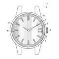
図1は、本発明の実施形態に係る太陽電池付き腕時計1を示す平面図である。図1には、ベゼル2a、見返しリング2b、文字板3、渦巻き模様4a、時字5、日窓6、指針7、竜頭8が示されている。また、図2は、図1のII−II線における太陽電池付き時計1の断面図である。図2には、ベゼル2a、見返しリング2b、時字5、風防9、胴10、裏蓋11、ムーブメント12、光透過性基板20及び光透過性反射板21から構成される文字板3、太陽電池30が示されている。
[First Embodiment]
FIG. 1 is a plan view showing a wristwatch 1 with a solar cell according to an embodiment of the present invention. FIG. 1 shows a bezel 2a, a dial ring 2b, a dial plate 3, a spiral pattern 4a, a time letter 5, a date window 6, a pointer 7, and a crown 8. 2 is a cross-sectional view of the solar cell timepiece 1 taken along the line II-II in FIG. FIG. 2 shows a dial 3 composed of a bezel 2a, a dial ring 2b, a time character 5, a windshield 9, a trunk 10, a back cover 11, a movement 12, a light transmissive substrate 20 and a light transmissive reflector 21, a sun A battery 30 is shown.

なお、図1に示した太陽電池付き時計1のデザインは一例にすぎない。ここで示したもの以外にも、例えば、文字板3及び太陽電池付き時計1の外形形状を、丸型でなく角型にしてもよいし、見返しリング2bに秒を表示するインデックスを付けてもよい。また、見返しリング2bは無くてもよい。本実施形態では、指針7を時針、分針の2本としているが、秒針を加えることとしてもよく、日窓6には日付を表示することとするが、それに限らず、曜日を表示することとしてもよい。また、タイムゾーンやサマータイムの有無、電池の残量、各種の表示を行う補助指針を備えることとしてもよい。その場合、ベゼル2aの外側に、竜頭8の他にボタンを備えることとして、ユーザが種々の操作を行えるようにしてもよい。   The design of the solar cell timepiece 1 shown in FIG. 1 is merely an example. In addition to those shown here, for example, the outer shape of the dial 3 and the solar cell timepiece 1 may be a square shape instead of a round shape, or an index for displaying the second may be attached to the dial ring 2b. Good. Further, the facing ring 2b may be omitted. In the present embodiment, the hands 7 are the hour hand and the minute hand. However, the second hand may be added, and the date is displayed on the date window 6, but not limited thereto, the day of the week is displayed. Also good. Moreover, it is good also as providing the auxiliary | assistant pointer | guide which performs the presence or absence of a time zone or daylight saving time, the battery remaining amount, and various displays. In that case, the user may be able to perform various operations by providing a button in addition to the crown 8 on the outside of the bezel 2a.

太陽電池付き時計1には、文字板3を覆うように、ガラス等の透明材料により形成された風防9がベゼル2aに取り付けられている。また、胴10、ベゼル2a、見返しリング2b、及び風防9が一体となった外装部品には、文字板3、太陽電池30、及びムーブメント12が収容されており、裏側は裏蓋11によって閉じられている。本明細書では、太陽電池付き時計1の風防9が配置される側(図2における紙面上側)を表側、裏蓋11が配置される側(図2における紙面下側)を裏側、及び、表側及び裏側に対応した面を、それぞれ、表側の面及び裏側の面と呼ぶこととする。   A windshield 9 made of a transparent material such as glass is attached to the bezel 2 a so as to cover the dial 3 in the solar cell timepiece 1. In addition, the dial 3, the solar cell 30, and the movement 12 are accommodated in the exterior part in which the body 10, the bezel 2a, the turn ring 2b, and the windshield 9 are integrated, and the back side is closed by the back cover 11. ing. In this specification, the side (upper side in FIG. 2) on which the windshield 9 of the solar cell timepiece 1 is arranged is the front side, the side on which the back cover 11 is arranged (lower side in FIG. 2) is the back side, and the front side. The surfaces corresponding to the back side and the back side are referred to as a front side surface and a back side surface, respectively.

文字板3の裏側には、太陽電池30が配置され、表側から入射した光により発電がなされる。そのため、文字板3を構成する光透過性基板20及び光透過性反射板21は、ある程度光を透過する材質で形成される。また、光透過性反射板21は、熱可塑性樹脂で形成され、光の反射率が30%〜70%と比較的高く、好ましくは金属様光沢を持つ。このような特性を持つ材質であれば、光透過性反射板21を形成する材質としてどのようなものを用いてもよいが、好適な例として、PET(polyethylene terephthalate)の多層積層により干渉反射を生じさせるフィルムを挙げることができる。このような光透過性反射板21は、裏側に配置された太陽電池30に光を透過させつつ、金属に似た光沢により文字板3の美観を向上させる。このような光透過性反射板21は、その材質上、あるいは構造上、耐熱温度が比較的低い場合があり、例えば、光透過性反射板21として東レ株式会社製のピカサス(登録商標)を使用した場合、その耐熱温度は60℃である。なお、光透過性反射板21の耐熱温度は、材料特性として示されることがある他、熱間プレスの適用可能温度の下限値として示される場合もある。また、光透光性基板20は、光透過性反射板21の表側に配置され、光透過性反射板21側(裏側)が凹凸面である。   A solar cell 30 is disposed on the back side of the dial 3 and power is generated by light incident from the front side. Therefore, the light-transmitting substrate 20 and the light-transmitting reflecting plate 21 constituting the dial plate 3 are formed of a material that transmits light to some extent. Moreover, the light transmissive reflecting plate 21 is formed of a thermoplastic resin and has a relatively high light reflectance of 30% to 70%, and preferably has a metallic luster. Any material having such characteristics may be used as the material for forming the light transmissive reflecting plate 21. As a preferred example, interference reflection is performed by multilayer lamination of PET (polyethylene terephthalate). Mention may be made of the resulting film. Such a light transmissive reflecting plate 21 improves the aesthetic appearance of the dial plate 3 with gloss similar to metal while allowing light to pass through the solar cell 30 arranged on the back side. Such a light transmissive reflector 21 may have a relatively low heat-resistant temperature due to its material or structure. For example, as the light transmissive reflector 21, a Picasas (registered trademark) manufactured by Toray Industries, Inc. is used. In this case, the heat resistant temperature is 60 ° C. In addition, the heat-resistant temperature of the light transmissive reflecting plate 21 may be indicated as a material characteristic, or may be indicated as a lower limit value of the applicable temperature of the hot press. The light transmissive substrate 20 is disposed on the front side of the light transmissive reflective plate 21, and the light transmissive reflective plate 21 side (back side) is an uneven surface.

図3は、本実施形態に係る太陽電池付き時計1の断面の拡大図である。図3は、図2に示す拡大領域50を拡大した図である。時字5が表側の面に配置された光透過性基板20は、裏側に凹凸面を有する。凹凸面の凸部の断面形状は三角形であり、頂角θは、例えば90°以下である。凸部を形成する三角形の斜面は、平滑面であり、光を反射しやすい面となっている。また、凹凸面の凹凸ピッチpは、例えば100μm以下である。ここで、凹凸ピッチpとは、凸部を形成する三角形の頂点間距離をいう。光透過性基板20の裏側には、光透過性反射板21が配置される。光透過性反射板21の裏側には、太陽電池30が配置される。なお、本実施形態では、光透過性基板20の裏側の凹凸面は、平面視において渦巻き模様4aを形成するが、模様は同心円模様であってもよい。ただし、同心円模様より渦巻き模様の方が、光の干渉による構造色の発生が抑制される。そのため、同心円模様よりも渦巻き模様を形成する方が望ましい。もっとも、光透過性基板20に同心円模様を形成して、文字板3の有する美観の一部として構造色を積極的に利用することとしてもよい。   FIG. 3 is an enlarged view of a cross section of the solar cell timepiece 1 according to the present embodiment. FIG. 3 is an enlarged view of the enlarged region 50 shown in FIG. The light-transmitting substrate 20 in which the time characters 5 are arranged on the front side surface has an uneven surface on the back side. The cross-sectional shape of the convex part of the irregular surface is a triangle, and the apex angle θ is, for example, 90 ° or less. The triangular slope forming the convex portion is a smooth surface and is a surface that easily reflects light. Further, the uneven pitch p of the uneven surface is, for example, 100 μm or less. Here, the concavo-convex pitch p means a distance between vertices of a triangle forming the convex portion. On the back side of the light transmissive substrate 20, a light transmissive reflecting plate 21 is disposed. A solar cell 30 is disposed on the back side of the light transmissive reflecting plate 21. In the present embodiment, the uneven surface on the back side of the light-transmitting substrate 20 forms the spiral pattern 4a in plan view, but the pattern may be a concentric pattern. However, the generation of structural colors due to light interference is suppressed in the spiral pattern than in the concentric pattern. Therefore, it is desirable to form a spiral pattern rather than a concentric pattern. However, it is also possible to form a concentric pattern on the light-transmitting substrate 20 and positively use the structural color as part of the beauty of the dial 3.

本実施形態に係る太陽電池付き時計1において、光透過性基板20の厚さは400μm〜500μmであり、光透過性反射板21の厚さは100μmである。過去に製造した時計に、この厚さの光透過性反射板21を標準的に用いていれば、同じ厚さのものを選択することにより、文字板3以外の部材の設計変更が不要となり、メリットが大きい。例えば、100μmの厚さで、反射率の種類が選択できる光透過性反射板21としては、前述のピカサス(登録商標)が適している。但し、文字板3を構成する光透過性反射板21の最適な厚さは100μmに限らず、過去に製造した時計に100μm以外の厚さの光透過性反射板21が標準的に用いている場合は、その厚さが最適である。   In the solar cell timepiece 1 according to this embodiment, the light transmissive substrate 20 has a thickness of 400 μm to 500 μm, and the light transmissive reflector 21 has a thickness of 100 μm. If the light transmissive reflecting plate 21 having this thickness is used as a standard in a watch manufactured in the past, it is not necessary to change the design of members other than the dial 3 by selecting the same thickness. The benefits are great. For example, the aforementioned Picasas (registered trademark) is suitable as the light transmissive reflector 21 having a thickness of 100 μm and a selectable reflectance type. However, the optimal thickness of the light-transmitting reflecting plate 21 constituting the dial plate 3 is not limited to 100 μm, and the light-transmitting reflecting plate 21 having a thickness other than 100 μm is typically used in a watch manufactured in the past. If so, its thickness is optimal.

太陽電池30は、表面に微小な凹凸を有する場合がある。例えば、アモルファスシリコン太陽電池の場合、プラズマCVD(Chemical Vapor Deposition)によりアモルファスシリコンの薄膜を形成するか、又はITO(Indium Tin Oxide)等の透明電極を形成すると、表面に直径数百μmのスパッタ痕が形成される場合がある。太陽電池30の表面にスパッタ痕があると、太陽電池付き時計1が光透過性反射板21の耐熱温度付近か、又はそれを上回る程度の高温、例えば自動車のダッシュボード中等、に置かれたとき、軟化した光透過性反射板21に太陽電池30のスパッタ痕が転写される場合がある。光透過性反射板21にスパッタ痕が転写されると、太陽電池付き時計1を再び冷却しても、転写されたスパッタ痕と同程度の大きさの点状変形痕が光透過性反射板21に残留して、文字板3の美観を損なう場合がある。なお、光透過性反射板21に残留する変形痕の形状は、太陽電池30のスパッタ痕の形状に応じて変化し、必ずしも点状とは限らず、線状等の場合もあり得る。   The solar cell 30 may have minute irregularities on the surface. For example, in the case of an amorphous silicon solar cell, when an amorphous silicon thin film is formed by plasma CVD (Chemical Vapor Deposition) or a transparent electrode such as ITO (Indium Tin Oxide) is formed, sputter traces with a diameter of several hundreds μm are formed on the surface. May be formed. When there is a sputter mark on the surface of the solar cell 30, the solar cell timepiece 1 is placed near the heat-resistant temperature of the light transmissive reflector 21 or at a temperature higher than that, for example, in the dashboard of an automobile. In some cases, the sputter traces of the solar cell 30 may be transferred to the softened light transmissive reflecting plate 21. When the sputter marks are transferred to the light transmissive reflector 21, even if the solar cell timepiece 1 is cooled again, the dot-shaped deformation marks having the same size as the transferred sputter marks are transferred to the light transmissive reflector 21. The appearance of the dial 3 may be impaired. It should be noted that the shape of the deformation trace remaining on the light transmissive reflector 21 varies depending on the shape of the sputtering trace of the solar cell 30 and is not necessarily a dot shape, but may be a linear shape or the like.

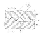
図4は、文字板3を正面から見た場合における光の反射を説明する図である。上述のように、太陽電池30のスパッタ痕が光透過性反射板21に転写されると、光透過性反射板21の表側の面に点状変形痕60が形成される場合がある。しかし、本実施形態に係る太陽電池付き時計1によれば、文字板3を正面から見た場合に、以下に説明する条件を満たす場合であれば、凹凸面の斜面で光が全反射されるため、凹凸面の裏側に形成された点状変形痕60が視認されづらくなる。その場合、文字板3を正面から見る観察者70は、光線経路61を進む光を視認するため、凹凸面の裏側に形成された点状変形痕60が視認しづらくなる。   FIG. 4 is a diagram for explaining the reflection of light when the dial 3 is viewed from the front. As described above, when the sputter traces of the solar cell 30 are transferred to the light transmissive reflective plate 21, the dotted deformation marks 60 may be formed on the surface on the front side of the light transmissive reflective plate 21. However, according to the timepiece 1 with the solar cell according to the present embodiment, when the dial 3 is viewed from the front, the light is totally reflected on the slope of the uneven surface if the following condition is satisfied. Therefore, it becomes difficult to visually recognize the point-like deformation marks 60 formed on the back side of the uneven surface. In that case, since the observer 70 who sees the dial 3 from the front visually recognizes the light traveling through the light beam path 61, it becomes difficult to visually recognize the dot-shaped deformation marks 60 formed on the back side of the uneven surface.

以下で、凹凸面の斜面で光が全反射されて、凹凸面の裏側に形成された点状変形痕60が最も視認しづらくなる条件について説明する。図4に示すように、光が入射角θiで凹凸面の斜面に入射する場合、反射角は入射角に等しく、θiである。ここで、観察者70の視線方向(文字板3に対して直交する方向)と凹凸面の斜面とがなす角は、π/2−θiラジアンである。図4から明らかなように、凹凸面の凸部を形成する三角形の頂角θとは、θ/2=π/2−θiの関係にある。なお、入射角及び反射角は、反射面(凹凸面の斜面)の法線から測った角度により定義されている。   In the following, a description will be given of a condition in which light is totally reflected on the slope of the concavo-convex surface and the point-shaped deformation mark 60 formed on the back side of the concavo-convex surface is most difficult to visually recognize. As shown in FIG. 4, when light is incident on the inclined surface of the concavo-convex surface at an incident angle θi, the reflection angle is equal to the incident angle and is θi. Here, the angle formed between the line of sight of the observer 70 (direction orthogonal to the dial 3) and the slope of the concavo-convex surface is π / 2−θi radians. As is apparent from FIG. 4, the apex angle θ of the triangle forming the convex portion of the concavo-convex surface has a relationship of θ / 2 = π / 2−θi. The incident angle and the reflection angle are defined by angles measured from the normal line of the reflection surface (the slope of the uneven surface).

凹凸面の斜面で全反射された光が観察者70によって視認される場合、文字板3を正面から見た場合に、凹凸面の裏側に形成された点状変形痕60が最も視認されづらくなると考えられる。光透過性反射板21の臨界角をθcと表すとき、全反射が起こるためには、θi≧θcでなければならない。よって、θ/2=π/2−θiの関係を考え合わせると、文字板3を正面から見た場合に、凹凸面の裏側に形成された点状変形痕60が最も視認されづらくなるための条件は、π/2−θ/2≧θcであることがわかる。例えば、臨界角が45°(π/4ラジアン)であれば、点状変形痕60が最も視認されづらくなるための条件は、θ≦π/2となり、頂角θが90°以下である場合に全反射が起こり、凹凸面の裏側に形成された点状変形痕60が視認されづらくなるとわかる。なお、臨界角は、光透過性基板20の屈折率をnとし、空気の屈折率を1とする時、sin(θc)=1/nの関係で定まる角度である。また、仮に凸部の頂角θが、π/2−θ/2≧θcという条件を満足しない場合であっても、凹凸面の裏側に形成された点状変形痕60が視認されづらい効果は発揮される。例えば、臨界角が45°で、凸部の頂角が90°よりもわずかに大きな場合であっても、凹凸面の斜面で透過する光の量が大幅に増えるのではなく、90°を越えた増加角度に応じてわずかに増えることとなる。従って、凹凸面の斜面で全反射が起こらない場合であっても、頂角に応じて光の一部は反射されるため、凹凸面を有しない場合に比べて点状変形痕60が視認されづらくなる。なお、光透過性反射板21に形成される変形痕が、表側の面以外の場所、例えば、表側の面が平らで変形せずに光透過性反射板21の裏側の面や内部が凹んだ状態で形成される場合であっても、光透過性基板20の裏側の凹凸面の斜面で光が全反射される上記の条件が満たされるのであれば、同様に変形痕は視認されづらくなる。   When the light totally reflected on the slope of the uneven surface is viewed by the observer 70, when the dial plate 3 is viewed from the front, the point-shaped deformation mark 60 formed on the back side of the uneven surface is most difficult to be viewed. Conceivable. When the critical angle of the light transmissive reflector 21 is expressed as θc, θi ≧ θc must be satisfied in order for total reflection to occur. Therefore, when considering the relationship of θ / 2 = π / 2−θi, when the dial plate 3 is viewed from the front, the point-shaped deformation marks 60 formed on the back side of the uneven surface are most difficult to be visually recognized. It can be seen that the condition is π / 2−θ / 2 ≧ θc. For example, if the critical angle is 45 ° (π / 4 radians), the condition for making the point-shaped deformation mark 60 most difficult to be visually recognized is θ ≦ π / 2, and the apex angle θ is 90 ° or less. It can be seen that total reflection occurs and the point-shaped deformation marks 60 formed on the back side of the uneven surface are difficult to be visually recognized. The critical angle is an angle determined by the relationship sin (θc) = 1 / n, where n is the refractive index of the light-transmitting substrate 20 and 1 is the refractive index of air. In addition, even if the apex angle θ of the convex portion does not satisfy the condition of π / 2−θ / 2 ≧ θc, the effect that it is difficult to visually recognize the point-like deformation marks 60 formed on the back side of the uneven surface is Demonstrated. For example, even when the critical angle is 45 ° and the apex angle of the convex portion is slightly larger than 90 °, the amount of light transmitted through the slope of the uneven surface does not increase significantly, but exceeds 90 °. It will increase slightly according to the increased angle. Therefore, even when total reflection does not occur on the slope of the uneven surface, a part of the light is reflected according to the apex angle, so that the point-like deformation mark 60 is visually recognized as compared with the case without the uneven surface. It becomes difficult. In addition, the deformation | transformation trace formed in the light transmissive reflecting plate 21 has a concave surface on the back side or the inside of the light transmissive reflecting plate 21 without being deformed at a place other than the surface on the front side, for example, the surface on the front side is flat. Even in the case of being formed in a state, if the above-described condition that the light is totally reflected by the inclined surface of the uneven surface on the back side of the light-transmitting substrate 20 is satisfied, the deformation trace is similarly difficult to be visually recognized.

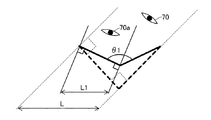
図5は、文字板3を斜めから見た場合における可視範囲を説明する図である。文字板3を斜めから見る場合のうち、光透過性反射板21に形成された点状変形痕60が最も視認されやすくなると考えられるのは、凹凸面の斜面で光の全反射が起こらない場合であり、凹凸面の斜面に直交する角度から文字板3を見る場合である。この場合、1つの凸部の斜面越しに、光透過性反射板21の表側の面のうち範囲Lの面が視認されることとなる。なお、図5において、厳密には、光透過性基板20表側の面では、その面状態に応じて屈折した光が観察者70に到達するが、可視範囲には影響しないため、図示を省略して簡略化して示している。文字板3を斜めから見た場合を示す他の図(後述する図6A、及び図6Bの場合)についても同様である。   FIG. 5 is a diagram for explaining the visible range when the dial 3 is viewed from an oblique direction. Among the cases where the dial 3 is viewed from an oblique direction, it is considered that the dot-shaped deformation marks 60 formed on the light-transmissive reflecting plate 21 are most easily recognized when light is not totally reflected on the uneven surface. In this case, the dial 3 is viewed from an angle orthogonal to the slope of the irregular surface. In this case, the surface of the range L among the surfaces on the front side of the light transmissive reflecting plate 21 is visually recognized over the slope of one convex portion. In FIG. 5, strictly speaking, the light refracted according to the surface state reaches the observer 70 on the surface on the front side of the light-transmitting substrate 20 but does not affect the visible range, and thus is not shown. And simplified. The same applies to other figures (in the case of FIGS. 6A and 6B described later) showing the dial 3 viewed from an oblique direction.

仮に、範囲Lに点状変形痕60の全体が収まる場合、観察者70は、文字板3を斜めから見る場合に点状変形痕60を視認できると考えられる。一方、範囲Lに点状変形痕60の全体が収まらない場合、すなわち範囲Lが点状変形痕60の大きさより小さい場合、点状変形痕60は複数の凸部の斜面により分断されて視認されることとなり、点状変形痕60が視認されづらくなると考えられる。従って、点状変形痕60の直径をDとするとき、文字板3を斜めから見る場合に点状変形痕60が視認されづらくなる条件は、L≦Dである。なお、光透過性反射板21に形成される変形痕が平面視において円形以外の形状である場合、変形痕を平面視した場合における変形痕の面積と等しい面積を有する円を考え、その直径をもって変形痕の大きさと定義することとしてよい。   If the entire point-shaped deformation mark 60 falls within the range L, it is considered that the observer 70 can visually recognize the point-shaped deformation mark 60 when viewing the dial plate 3 from an oblique direction. On the other hand, when the entire point-like deformation mark 60 does not fit in the range L, that is, when the range L is smaller than the size of the point-like deformation mark 60, the point-like deformation mark 60 is divided and visually recognized by the slopes of the plurality of convex portions. This is considered to make it difficult to visually recognize the point-like deformation mark 60. Therefore, when the diameter of the dotted deformation mark 60 is D, a condition that makes it difficult to visually recognize the dotted deformation mark 60 when the dial 3 is viewed obliquely is L ≦ D. When the deformation trace formed on the light-transmissive reflecting plate 21 has a shape other than a circle in plan view, consider a circle having an area equal to the area of the deformation trace when viewed in plan. It may be defined as the size of the deformation mark.

さらに、文字板3を斜めから見る場合は、光透過性基板20の表側の面を斜めから視認することとなるため、光透過性基板20の表側の面で生じる光の反射量が増え、これも点状変形痕60を視認されづらくしている。このように、文字板3を斜めから見る場合、凹凸面の山と谷の両方で点状変形痕60が分断されるようにも思われるため、点状変形痕60の直径Dと凹凸ピッチPとの関係が、D≧P/2であれば点状変形痕60が視認されづらくなるとも思われるが、上述のようにD≧Pであることが条件となる。   Further, when the dial 3 is viewed from an oblique direction, the surface on the front side of the light transmissive substrate 20 is viewed from an oblique direction, so that the amount of reflection of light generated on the surface on the front side of the light transmissive substrate 20 increases. Also, it is difficult for the dot-shaped deformation marks 60 to be visually recognized. Thus, when the dial 3 is viewed obliquely, it seems that the dotted deformation marks 60 are divided at both the peaks and valleys of the concave and convex surfaces, and therefore the diameter D and the concave and convex pitch P of the dotted deformation marks 60. If it is D ≧ P / 2, it seems that the point-like deformation mark 60 is difficult to be visually recognized, but the condition is that D ≧ P as described above.

次に、光透過性基板20における裏側の凸部の頂角が90°である場合と、90°以外の場合の視野範囲について説明する。光透過性基板20における裏側の凸部の頂角が90°の場合、凹凸面の斜面に直交する角度から文字板3を見たときの視野範囲Lは、凹凸ピッチPと等しくなる。この場合は、図5に示したピッチP内の2つの斜面が成す角度が90°となり、ピッチP内の右側の斜面に直交する角度から見ると、視線は、ピッチP内の左側の斜面と並行になるので、左側の斜面の先端部が視野範囲Lの端部になる。同様に、ピッチP内の右側の斜面の端部が視野範囲Lの他方の端部となるため、視野範囲Lは、図5に示したピッチP内の2つの斜面の両端の間の長さとなり、この長さはピッチPである。   Next, the visual field range when the apex angle of the convex part on the back side of the light-transmitting substrate 20 is 90 ° and when the vertex angle is other than 90 ° will be described. When the apex angle of the convex portion on the back side of the light transmissive substrate 20 is 90 °, the visual field range L when the dial 3 is viewed from an angle orthogonal to the slope of the concavo-convex surface is equal to the concavo-convex pitch P. In this case, the angle formed by the two slopes in the pitch P shown in FIG. 5 is 90 °, and when viewed from the angle orthogonal to the right slope in the pitch P, the line of sight is the left slope in the pitch P. Since they are parallel, the tip of the left slope becomes the end of the visual field range L. Similarly, since the end portion of the right slope in the pitch P becomes the other end portion of the visual field range L, the visual field range L is the length between both ends of the two slopes in the pitch P shown in FIG. This length is the pitch P.

図6Aは、光透過性基板20の裏側の凸部の頂角θ1が90°よりも大きな角度の場合における可視範囲を説明する図である。図6Bは、光透過性基板20の裏側の凸部の頂角θ2が90°よりも小さな角度の場合における可視範囲を説明する図である。図6A及び図6Bでは、光透過性基板20の裏側の凸部の頂角が90°の場合を破線で描くとともに、要部を拡大し、他の部分は図示を省略している。   FIG. 6A is a diagram illustrating the visible range when the apex angle θ1 of the convex portion on the back side of the light-transmitting substrate 20 is an angle larger than 90 °. FIG. 6B is a diagram illustrating the visible range when the apex angle θ2 of the convex portion on the back side of the light transmissive substrate 20 is an angle smaller than 90 °. In FIG. 6A and FIG. 6B, the case where the apex angle of the convex part on the back side of the light-transmitting substrate 20 is 90 ° is drawn with a broken line, the main part is enlarged, and the other parts are not shown.

図6Aの実線で示すように、光透過性基板20の裏側の凸部の頂角θ1が90°よりも大きい場合には、観察者70aが凹凸面の斜面に直交する方向から文字板3を見ると、光透過性反射板21の表面における範囲L1が視認されることとなる。範囲L1は、図6Aの破線で示した凸部の頂角が90°の場合における観察者70の可視範囲Lよりも狭い。   As shown by the solid line in FIG. 6A, when the apex angle θ1 of the convex portion on the back side of the light transmissive substrate 20 is larger than 90 °, the observer 70a moves the dial 3 from the direction perpendicular to the slope of the concavo-convex surface. When viewed, the range L1 on the surface of the light transmissive reflecting plate 21 is visually recognized. The range L1 is narrower than the visible range L of the observer 70 when the apex angle of the convex portion indicated by the broken line in FIG. 6A is 90 °.

また、図6Bの実線で示すように、光透過性基板20の裏側の凸部の頂角θ2が90°よりも小さい場合には、観察者70bが凹凸面の斜面に直交する方向から文字板3を見ると、光透過性反射板21の表面における範囲L2が視認されることとなる。範囲L2は、図6Bの破線で示した凸部の頂角が90°の場合における観察者70の可視範囲Lよりも狭い。なお、図6Bにおいて、頂点Taを通る線S1よりも頂点Tb側の領域は、頂点Ta〜Tb間の斜面によって視野が遮られる。同様に、頂点Tdを通る線S2よりも頂点Tc側の領域は、頂点Tc〜Tdの斜面によって視野が遮られる。このように、観察者70bが凹凸面の斜面に直交する方向から文字板3を見る場合、光透過性基板20の裏側の凸部の頂角が90°のときに最も視野が広くなる。   In addition, as shown by the solid line in FIG. 6B, when the apex angle θ2 of the convex portion on the back side of the light-transmitting substrate 20 is smaller than 90 °, the observer 70b dials the dial from the direction perpendicular to the slope of the uneven surface. 3, a range L <b> 2 on the surface of the light transmissive reflecting plate 21 is visually recognized. The range L2 is narrower than the visible range L of the observer 70 when the apex angle of the convex portion indicated by the broken line in FIG. 6B is 90 °. In FIG. 6B, the field of view of the region on the vertex Tb side of the line S1 passing through the vertex Ta is blocked by the slope between the vertices Ta to Tb. Similarly, the visual field of the region on the vertex Tc side of the line S2 passing through the vertex Td is blocked by the slopes of the vertices Tc to Td. Thus, when the observer 70b views the dial 3 from a direction orthogonal to the slope of the concavo-convex surface, the field of view becomes the widest when the apex angle of the convex portion on the back side of the light-transmitting substrate 20 is 90 °.

本発明の発明者らは、上述の理論を裏付けるため、凸部の頂角θが90°であり、凹凸ピッチPが、50μm、100μm、及び150μmである光透過性基板20をそれぞれ作成し、点状変形痕60がどの程度視認されるか実験した。その結果、凹凸ピッチPが150μmの場合には点状変形痕60が視認され、凹凸ピッチPが100μmの場合には点状変形痕60がほとんど視認されず、凹凸ピッチPが50μmの場合には点状変形痕60がまったく視認されなかった。ここで、点状変形痕60のうち直径が100μm以下のものはそもそも視認できないため、視認され得る変形痕の大きさは100μm程度であると考えられる。そのため、凹凸ピッチPが100μm以下であれば点状変形痕60がほとんど視認されないという実験結果は、上述の理論に合致するものである。なお、凹凸面の斜面に直交する角度と、正面との間の角度から文字板3を見る場合には、凹凸面の斜面で光が全反射することと、複数の凸部により点状変形痕60が分断されて視認されることの両方の理由により、点状変形痕60が視認されづらくなると考えられる。また、光透過性反射板21に形成される変形痕が、表側の面以外の場所、例えば光透過性反射板21の裏側の面や内部、に形成される場合であっても、変形痕が複数の凸部により分断される上記の条件が満たされる場合には、同様に変形痕は視認されづらくなる。   In order to support the above-mentioned theory, the inventors of the present invention respectively create a light-transmitting substrate 20 in which the apex angle θ of the convex portion is 90 ° and the uneven pitch P is 50 μm, 100 μm, and 150 μm, An experiment was conducted to see how much the dot-shaped deformation mark 60 is visually recognized. As a result, when the concavo-convex pitch P is 150 μm, the spot-shaped deformation marks 60 are visually recognized. When the concavo-convex pitch P is 100 μm, the point-shaped deformation marks 60 are hardly visible, and when the concavo-convex pitch P is 50 μm. The dotted deformation marks 60 were not visually recognized at all. Here, since the thing with a diameter of 100 micrometers or less among the dotted | punctate deformation traces 60 cannot be visually recognized in the first place, it is thought that the magnitude | size of the deformation | transformation traces which can be visually recognized is about 100 micrometers. Therefore, the experimental result that the spot-like deformation marks 60 are hardly visually recognized if the uneven pitch P is 100 μm or less is consistent with the above theory. When the dial 3 is viewed from the angle between the angle perpendicular to the slope of the concavo-convex surface and the front surface, light is totally reflected on the slope of the concavo-convex surface, and the point-shaped deformation traces are caused by the plurality of convex portions. It is considered that the point-shaped deformation marks 60 are difficult to be visually recognized for both reasons that the 60 is divided and visually recognized. Further, even if the deformation trace formed on the light transmissive reflective plate 21 is formed on a place other than the surface on the front side, for example, on the back surface or inside of the light transmissive reflective plate 21, the deformation trace is not present. Similarly, when the above-described condition of being divided by a plurality of convex portions is satisfied, it is difficult to visually recognize the deformation trace.

上述の理論、及び実験結果に基づくと、光透過性基板20の裏側の凸部の頂角が90°のときに視野が最も広くなるので、光透過性基板20の裏側のピッチが100μm以下であれば、光透過性基板20の裏側の凸部の頂角が180°未満の任意の角度において、点状変形痕60は複数の凸部の斜面により分断されて視認されることとなり、点状変形痕60が視認されづらくなる。しかも、凸部の頂角の角度を変えるようなデザイン変更が生じたり、凸部の頂角が精度良く90°に形成できなくても、光透過性基板20の裏側のピッチを変更又は修正する必要がない。すなわち、光透過性基板20の裏側のピッチを100μm以下に設定することによって、文字板3への光透過性基板20の適用が容易になる。さらに、光透過性基板20の裏側の凸部の頂角が90°以上の場合には、次のように、点状変形痕60を視認されづらくするための、点状変形痕60の直径Dと凹凸ピッチPとの関係を求めることができる。   Based on the above theory and experimental results, the field of view is the widest when the apex angle of the convex portion on the back side of the light-transmitting substrate 20 is 90 °, so the pitch on the back side of the light-transmitting substrate 20 is 100 μm or less. If there is, the point-like deformation marks 60 are divided by the slopes of the plurality of convex portions and viewed at an arbitrary angle where the apex angle of the convex portion on the back side of the light-transmitting substrate 20 is less than 180 °. It becomes difficult to visually recognize the deformation mark 60. Moreover, even if a design change that changes the apex angle of the convex portion occurs or the apex angle of the convex portion cannot be accurately formed at 90 °, the pitch on the back side of the light transmissive substrate 20 is changed or corrected. There is no need. That is, by setting the pitch on the back side of the light transmissive substrate 20 to 100 μm or less, the light transmissive substrate 20 can be easily applied to the dial 3. Furthermore, when the apex angle of the convex part on the back side of the light-transmitting substrate 20 is 90 ° or more, the diameter D of the spot-like deformation mark 60 for making it difficult to visually recognize the point-like deformation mark 60 as follows. And the concavo-convex pitch P can be obtained.

図5より読み取れるように、凸部の斜面の長さは、P/(2cos(π/2−θ/2))である。斜面の長さの1/cos(π/2−θ/2)がLであるから、範囲Lと、凸部の頂角θ及び凹凸ピッチPとの関係は、L=P/(2cos(π/2−θ/2))となる。従って、凸部の頂角が90°以上の場合に、点状変形痕60が視認されづらくなるための凸部の頂角θ及び凹凸ピッチPに対する条件は、D≧P/(2cos(π/2−θ/2))となる。例えば、凸部の頂角θが直角(π/2ラジアン)である場合、D≧Pとなり、凹凸ピッチが点状変形痕60の大きさより小さい場合に、点状変形痕60が視認されづらくなる。このように、光透過性基板20の裏側の凸部の頂角が90°以上の場合には、D≧P/(2cos(π/2−θ/2))という条件式に基づいて、凹凸ピッチPを100μmよりも大きな値に設定することにより、更なる文字板3のデザインの多様化も可能である。 As can be seen from FIG. 5, the length of the slope of the convex portion is P / (2 cos (π / 2−θ / 2)). Since 1 / cos (π / 2−θ / 2) of the length of the slope is L, the relationship between the range L and the apex angle θ of the convex portion and the concave / convex pitch P is L = P / (2cos 2 ( π / 2−θ / 2)). Therefore, when the apex angle of the convex portion is 90 ° or more, the condition for the apex angle θ of the convex portion and the concave / convex pitch P for making it difficult to visually recognize the point-shaped deformation mark 60 is D ≧ P / (2cos 2 (π / 2-θ / 2)). For example, when the apex angle θ of the convex portion is a right angle (π / 2 radians), D ≧ P, and when the concavo-convex pitch is smaller than the size of the point-like deformation mark 60, the point-like deformation mark 60 is difficult to be visually recognized. . Thus, when the apex angle of the convex part on the back side of the light transmissive substrate 20 is 90 ° or more, based on the conditional expression D ≧ P / ( 2 cos 2 (π / 2−θ / 2)), By setting the concavo-convex pitch P to a value larger than 100 μm, the design of the dial 3 can be further diversified.

光透過性反射板21の表側の面には、艶消し層を設けてもよい。光透過性反射板21の表側の面に艶消し層を設けると、光が拡散され、光透過性反射板21に形成される点状変形痕がさらに視認されづらくなる。また、光透過性基板20が光透過性反射板21に貼り付くことによりモアレ模様が生じるのを防ぐことができる。   A matte layer may be provided on the front surface of the light transmissive reflector 21. If a matte layer is provided on the front surface of the light transmissive reflector 21, light is diffused, and the dot-shaped deformation marks formed on the light transmissive reflector 21 are more difficult to visually recognize. Further, it is possible to prevent the moire pattern from being generated when the light-transmitting substrate 20 is attached to the light-transmitting reflecting plate 21.

光透過性反射板21の表側の面には、光透過性有色層を設けてもよい。光透過性反射板21の表側の面に光透過性有色層を設けると、特定の波長の光の透過が妨げられ、光透過性反射板21に形成される点状変形痕がさらに視認されづらくなる。また、光透過性有色層と艶消し層とを組み合わせた構成を採用してもよい。その場合、艶消し層の表面に形成された凹凸を埋めないように、光透過性有色層は艶消し層の裏側に形成することが望ましい。すなわち、光透過性反射板21の表側に光透過性有色層を形成し、光透過性有色層の表側に艶消し層を形成することが望ましい。   A light-transmitting colored layer may be provided on the front surface of the light-transmitting reflecting plate 21. If a light-transmitting colored layer is provided on the surface of the light-transmitting reflecting plate 21, the transmission of light of a specific wavelength is hindered, and the point-shaped deformation marks formed on the light-transmitting reflecting plate 21 are more difficult to visually recognize. Become. Moreover, you may employ | adopt the structure which combined the light transmissive colored layer and the matte layer. In that case, it is desirable to form the light-transmitting colored layer on the back side of the matte layer so as not to fill the irregularities formed on the surface of the matte layer. That is, it is desirable to form a light transmissive colored layer on the front side of the light transmissive reflective plate 21 and to form a matte layer on the front side of the light transmissive colored layer.

光透過性基板20の表側の面には、艶消し層を設けてもよい。光透過性基板20の表側の面に艶消し層を設けると、光が拡散され、光透過性反射板21に形成される点状変形痕がさらに視認されづらくなる。当然ながら、上記の構成を組み合わせた構成を採用することとしてもよい。   A matte layer may be provided on the front surface of the light transmissive substrate 20. If a matte layer is provided on the front surface of the light-transmitting substrate 20, light is diffused, and the point-shaped deformation marks formed on the light-transmitting reflecting plate 21 are more difficult to visually recognize. Of course, it is good also as employ | adopting the structure which combined said structure.

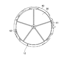
図7は、太陽電池30を収めた中枠40を示す平面図である。中枠40は、内部にムーブメント12等を収めるケースである。太陽電池30は、ムーブメント12の表側に重ねて配置される。太陽電池30は、太陽電池30の周縁に形成された切り欠きと、中枠40の周縁に形成された切り欠きと、を合わせるように配置することで位置合わせされて配置される。中枠40は、第1嵌合部41と第2嵌合部42とを有する。第1嵌合部41及び第2嵌合部42は、太陽電池30の表側に重ねて配置される光透過性反射板21の位置合わせ及び光透過性基板20の嵌合のための部材である。   FIG. 7 is a plan view showing the middle frame 40 in which the solar cells 30 are housed. The middle frame 40 is a case for accommodating the movement 12 and the like inside. The solar cell 30 is arranged so as to overlap the front side of the movement 12. The solar cell 30 is positioned and arranged by aligning the notch formed on the periphery of the solar cell 30 with the notch formed on the periphery of the middle frame 40. The middle frame 40 includes a first fitting part 41 and a second fitting part 42. The first fitting portion 41 and the second fitting portion 42 are members for aligning the light transmissive reflecting plate 21 and overlapping the light transmissive substrate 20 that are arranged on the front side of the solar cell 30. .

図8は、中枠40に配置された光透過性反射板21を示す平面図である。光透過性反射板21は、中枠40の有する第1嵌合部41及び第2嵌合部42により位置合わせされる。光透過性基板20が第1嵌合部41及び第2嵌合部42に嵌合により固定されることで、光透過性反射板21は、中枠40から脱落することなく保持される。このとき、光透過性反射板21と太陽電池30とは、互いに接触し、互いに押圧された状態で固定される。このことが、太陽電池30のスパッタ痕が光透過性反射板21に転写される要因の1つである。なお、図7、図8に示した太陽電池30及び光透過性反射板21の固定構造は一例である。このような構造に限らず、文字板3を構成する部材が動かないようにするためには、光透過性反射板21を太陽電池30に対して押圧した状態で固定することが必要である。   FIG. 8 is a plan view showing the light transmissive reflecting plate 21 arranged in the middle frame 40. The light transmissive reflecting plate 21 is aligned by the first fitting portion 41 and the second fitting portion 42 of the middle frame 40. The light transmissive substrate 20 is held without dropping from the middle frame 40 by fixing the light transmissive substrate 20 to the first fitting portion 41 and the second fitting portion 42 by fitting. At this time, the light transmissive reflecting plate 21 and the solar cell 30 are in contact with each other and fixed in a pressed state. This is one of the factors that cause the sputter marks of the solar cell 30 to be transferred to the light transmissive reflector 21. In addition, the fixing structure of the solar cell 30 and the light transmissive reflecting plate 21 shown in FIGS. 7 and 8 is an example. In order to prevent the members constituting the dial 3 from moving without being limited to such a structure, it is necessary to fix the light transmissive reflecting plate 21 in a pressed state against the solar cell 30.

太陽電池30のスパッタ痕が光透過性反射板21に転写されているか否かは、以下の方法で判別することができる。はじめに、スパッタ痕を有する場合がある太陽電池30を用意する。太陽電池付き時計が製品として使用される条件を再現するため、太陽電池30は、中枠40に配置した状態で用意することが望ましい。   Whether or not the sputter traces of the solar cell 30 are transferred to the light transmissive reflecting plate 21 can be determined by the following method. First, a solar cell 30 that may have a sputter mark is prepared. In order to reproduce the conditions under which the solar cell timepiece is used as a product, it is desirable to prepare the solar cell 30 in a state of being disposed in the middle frame 40.

次に、太陽電池30の表側に、光透過性反射板21と光透過性基板20を配置する。光透過性反射板21は、中枠40の有する第1嵌合部41及び第2嵌合部42により位置合わせされ、光透過性基板20は、これらの嵌合部に嵌合させて固定することが望ましい。   Next, the light transmissive reflecting plate 21 and the light transmissive substrate 20 are disposed on the front side of the solar cell 30. The light transmissive reflecting plate 21 is aligned by the first fitting portion 41 and the second fitting portion 42 of the middle frame 40, and the light transmissive substrate 20 is fitted and fixed to these fitting portions. It is desirable.

その後、太陽電池30、光透過性反射板21、及び光透過性基板20を、太陽電池付き時計1について要求される耐熱温度である所定の温度、例えば60℃、に加熱する。加熱により光透過性反射板21が軟化する場合、太陽電池30の有するスパッタ痕が光透過性反射板21に転写されることがある。   Thereafter, the solar cell 30, the light transmissive reflector 21, and the light transmissive substrate 20 are heated to a predetermined temperature that is a heat-resistant temperature required for the solar cell timepiece 1, for example, 60 ° C. When the light transmissive reflecting plate 21 is softened by heating, the sputter marks of the solar cell 30 may be transferred to the light transmissive reflecting plate 21.

最後に、光透過性反射板21の表側の面、内部、裏側の面を観察する。それにより、光透過性反射板21に、点状変形痕等の変形痕が形成されているか否かを検査する。   Finally, the front side surface, the inside, and the back side surface of the light transmissive reflecting plate 21 are observed. Thereby, it is inspected whether or not deformation traces such as dot-like deformation traces are formed on the light transmissive reflecting plate 21.

光透過性反射板21に点状変形痕等の変形痕が観察される場合であっても、以下の方法で変形痕が視認されづらい太陽電池付き時計を設計することができる。はじめに、光透過性反射板21において観察された変形痕のうち、視認され得るものの大きさを測定する。ここで、変形痕の大きさとは、変形痕が点状変形痕である場合には、点状変形痕を平面視した場合における点状変形痕の直径である。また、変形痕が点状変形痕でない場合には、変形痕を平面視した場合における変形痕の面積と等しい面積を有する円を考え、その直径を変形痕の大きさとしてよい。   Even when deformation marks such as dot-shaped deformation marks are observed on the light-transmissive reflecting plate 21, it is possible to design a watch with a solar cell in which the deformation marks are difficult to be visually recognized by the following method. First, the size of what can be visually recognized among the deformation | transformation traces observed in the light transmissive reflecting plate 21 is measured. Here, the size of the deformation mark is the diameter of the point-like deformation mark when the deformation mark is a point-like deformation mark when viewed in plan. When the deformation trace is not a point-like deformation trace, a circle having an area equal to the area of the deformation trace when the deformation trace is viewed in plan may be considered, and the diameter of the circle may be the size of the deformation trace.

次に、視認され得る変形痕の大きさの測定結果に基づいて、光透過性基板20の裏側の面に形成する凹凸面の凹凸ピッチを設定する。凹凸ピッチの上限値は、すべての大きさの変形痕が視認されづらくなるように定められる。凹凸ピッチは、その上限値を下回るようにしつつ、文字板3に明瞭な模様が表れるように調整することで定められてよい。凹凸ピッチは、光透過性基板20の屈折率から導かれる臨界角に基づいて設計し、視認され得る変形痕の大きさの測定結果に基づいて調整することとしてよい。   Next, the concavo-convex pitch of the concavo-convex surface formed on the back surface of the light transmissive substrate 20 is set based on the measurement result of the size of the deformation trace that can be visually recognized. The upper limit value of the uneven pitch is determined so that deformation marks of all sizes are difficult to be visually recognized. The concavo-convex pitch may be determined by adjusting so that a clear pattern appears on the dial 3 while being below the upper limit value. The concavo-convex pitch may be designed based on a critical angle derived from the refractive index of the light-transmitting substrate 20, and may be adjusted based on a measurement result of the size of deformation marks that can be visually recognized.

本実施形態に係る太陽電池付き時計1では、太陽電池30の表側の面に形成されたスパッタ痕等である突起により、光透過性反射板21に点状変形痕等の変形痕が形成される場合がある。その場合であっても、光透過性基板20を光透過性反射板21の表側に重ねて配置し、一体に固定する方法を文字板3に適用することによって、変形痕を隠すことができる。光透過性基板20は、その裏面に凸部の断面形状が三角形であって、凹凸ピッチが100μm以下の凹凸面が形成される。そのため、上述の理由により、文字板3を正面又は斜めから見た場合に、光透過性反射板21に形成された変形痕が視認されづらくなる。光透過性基板20は、光透過性反射板21を押さえ付けて固定される。そのため、光透過性反射板21に形成される変形痕によって光透過性基板20に同様な変形痕が形成されないように、光透過性基板20の材質として、少なくとも60℃では変形しない材質を用いる必要がある。ここで、光透過性反射板21は、60℃以下で変形する材質を用いて形成されてよいため、換言すると、光透過性基板20は、光透過性反射板21よりも耐熱温度が高い材質を用いて形成される。   In the timepiece 1 with a solar cell according to the present embodiment, deformation marks such as dotted deformation marks are formed on the light transmissive reflector 21 by protrusions such as sputter marks formed on the front surface of the solar cell 30. There is a case. Even in such a case, the deformation trace can be hidden by applying a method in which the light-transmitting substrate 20 is placed on the front side of the light-transmitting reflecting plate 21 and is fixed to the dial 3. The light-transmitting substrate 20 has a concavo-convex surface having a triangular cross-sectional shape on the back surface and a concavo-convex pitch of 100 μm or less. For this reason, when the dial 3 is viewed from the front or obliquely, the deformation marks formed on the light transmissive reflecting plate 21 are difficult to be visually recognized. The light transmissive substrate 20 is fixed by pressing the light transmissive reflecting plate 21. Therefore, it is necessary to use a material that does not deform at least at 60 ° C. as the material of the light transmissive substrate 20 so that the similar deformation marks are not formed on the light transmissive substrate 20 due to the deformation marks formed on the light transmissive reflector 21. There is. Here, since the light transmissive reflecting plate 21 may be formed using a material that is deformed at 60 ° C. or lower, in other words, the light transmissive substrate 20 is a material having a higher heat resistance temperature than the light transmissive reflecting plate 21. It is formed using.

[第2の実施形態]
図9は、本発明の第2の実施形態に係る太陽電池付き時計1を示す平面図である。本実施形態に係る太陽電池付き時計1と、図1に示す第1の実施形態に係る太陽電池付き時計1との違いは、平面視において、文字板3に複数の線模様であるストライプ模様4bが表れている点である。ストライプ模様4bは、光透過性基板20の裏側の凹凸面により形成される。ストライプ模様4bは、12時方向から6時方向に伸びる凹凸により形成され、凹凸ピッチは、例えば100μm以下である。ここで、凹凸ピッチとは、隣接する凸部の頂点間距離である。凸部の断面形状は三角形であり、その頂角は、例えば90°以下である。
[Second Embodiment]
FIG. 9 is a plan view showing a timepiece 1 with a solar cell according to the second embodiment of the present invention. The difference between the solar cell timepiece 1 according to this embodiment and the solar cell timepiece 1 according to the first embodiment shown in FIG. 1 is that the dial 3 has a plurality of line patterns 4b in a plan view. This is the point that appears. The stripe pattern 4 b is formed by an uneven surface on the back side of the light transmissive substrate 20. The stripe pattern 4b is formed by unevenness extending from 12 o'clock to 6 o'clock, and the uneven pitch is, for example, 100 μm or less. Here, the uneven pitch is the distance between the apexes of adjacent convex portions. The cross-sectional shape of the convex portion is a triangle, and the apex angle is, for example, 90 ° or less.

本実施形態に係る太陽電池付き時計1によれば、光透過性反射板21に視認され得る大きさの点状変形痕が形成されても、点状変形痕が2以上の凹凸により分離されて視認されることとなり、点状変形痕がより視認されづらくなる。また、ストライプ模様4bが12時−6時方向に延びることにより、文字板3を6時方向から斜めに見るか、又は文字板3を正面から見る場合に、凹凸を構成する斜面を斜めから見ることになり、斜面で光が反射されるため点状変形痕がより視認されづらくなる。一方、文字板3を3時方向又は9時方向から斜めに見る場合、凹凸を構成する斜面と直交する方向から当該斜面を見ることになり、光の透過量が多くなり点状変形痕が視認されやすくなってしまう。文字板3は、6時方向から斜めに見るか、又は文字板3を正面から見るのが通常であるから、本実施形態のようにストライプ模様4bを12時−6時方向に延びるように形成することで、点状変形痕をより視認しづらくすることができる。また、光透過性基板20の裏側の凹凸面の凸部を形成する三角形の頂角θが、光透過性基板20の臨界角θcとの間で、π/2−θ/2≧θcの条件を満足すれば、凹凸面の斜面で光が全反射して点状変形痕が最も視認されづらくなる。具体的に、臨界角θcが45°の場合、凸部の頂角θが90°以下であれば、点状変形痕が最も視認されづらくなる。また、視認され得る点状変形痕の大きさを100μmとするとき、凹凸ピッチPが100μm以下であれば、凸部の頂角の角度θに依存せず、文字板3を斜めから見た場合であっても、点状変形痕が2以上の凹凸により分離されて視認されることとなり、点状変形痕がより視認されづらくなる。   According to the solar cell timepiece 1 according to the present embodiment, even if a spot-shaped deformation mark having a size that can be visually recognized is formed on the light-transmissive reflective plate 21, the dot-shaped deformation mark is separated by two or more irregularities. It will be visually recognized, and it becomes difficult to visually recognize the point-like deformation trace. Further, the stripe pattern 4b extends in the 12 o'clock to 6 o'clock direction, so that the dial plate 3 is viewed obliquely from the 6 o'clock direction, or when the dial plate 3 is viewed from the front, the slopes constituting the irregularities are viewed obliquely. In other words, since the light is reflected on the inclined surface, the point-like deformation marks are more difficult to be visually recognized. On the other hand, when the dial 3 is viewed obliquely from the 3 o'clock direction or the 9 o'clock direction, the inclined surface is viewed from a direction orthogonal to the inclined surface forming the unevenness, and the amount of light transmission increases and the point-like deformation marks are visually recognized. It becomes easy to be done. Since the dial plate 3 is usually viewed obliquely from the 6 o'clock direction or the dial plate 3 is viewed from the front, the stripe pattern 4b is formed to extend in the 12 o'clock to 6 o'clock direction as in this embodiment. By doing so, it becomes difficult to visually recognize the point-like deformation trace. Further, a condition where π / 2−θ / 2 ≧ θc is established between the apex angle θ of the triangle forming the convex portion of the uneven surface on the back side of the light transmissive substrate 20 and the critical angle θc of the light transmissive substrate 20. If satisfied, the light is totally reflected on the slope of the uneven surface, and the point-shaped deformation marks are hardest to be visually recognized. Specifically, when the critical angle θc is 45 °, if the apex angle θ of the convex portion is 90 ° or less, the point-shaped deformation traces are most difficult to be visually recognized. In addition, when the size of the spot-like deformation mark that can be visually recognized is 100 μm, when the uneven pitch P is 100 μm or less, the dial 3 is viewed obliquely without depending on the apex angle θ of the protrusions. Even so, the point-like deformation marks are separated and visually recognized by the two or more irregularities, and the point-like deformation marks are more difficult to be visually recognized.

[第3の実施形態]
図10は、本発明の第3の実施形態に係る太陽電池付き時計1を示す平面図である。本実施形態に係る太陽電池付き時計1と、図1に示す第1の実施形態に係る太陽電池付き時計1との違いは、文字板3に四角錐模様4cが表れている点である。プリズム模様4cは、光透過性基板20の裏側の凹凸面により形成される。四角錐模様4cは、光透過性基板20の裏側の面から裏側に向かって突出する四角錐形状により形成される。四角錐模様4cは、模様を形成する四角錐の稜線が12時−6時方向に延びるように形成され、凹凸ピッチは、例えば100μm以下である。本実施形態の場合、凹凸ピッチとは、隣接する四角錐の頂点間の距離である。四角錐は正四角錐であり、断面形状は三角形である。当該三角形の頂角は、例えば90°以下である。
[Third Embodiment]
FIG. 10 is a plan view showing a solar cell timepiece 1 according to the third embodiment of the present invention. The difference between the solar cell timepiece 1 according to the present embodiment and the solar cell timepiece 1 according to the first embodiment shown in FIG. 1 is that a square pyramid pattern 4 c appears on the dial 3. The prism pattern 4 c is formed by an uneven surface on the back side of the light transmissive substrate 20. The quadrangular pyramid pattern 4 c is formed in a quadrangular pyramid shape protruding from the back surface of the light transmissive substrate 20 toward the back side. The quadrangular pyramid pattern 4c is formed such that the ridge line of the quadrangular pyramid forming the pattern extends in the 12 o'clock to 6 o'clock direction, and the uneven pitch is, for example, 100 μm or less. In this embodiment, the uneven pitch is the distance between the apexes of adjacent quadrangular pyramids. The quadrangular pyramid is a regular quadrangular pyramid, and the cross-sectional shape is a triangle. The apex angle of the triangle is, for example, 90 ° or less.

本実施形態に係る太陽電池付き時計1によれば、光透過性基板20の凹凸面により、光透過性反射板21に視認され得る大きさの点状変形痕が形成されても、点状変形痕が2以上の凹凸により分離されて視認されることとなり、点状変形痕がより視認されづらくなる。また、四角錐模様4cを形成する四角錐の稜線が12時−6時方向に延びることにより、文字板3を6時方向から斜めに見るか、又は文字板3を正面から見る場合に、四角錐を構成する斜面を斜めから見ることになり、当該斜面で光が反射されるため点状変形痕がより視認されづらくなる。一方、文字板3を3時方向又は9時方向から斜めに見る場合、四角錐を構成する斜面と直交する方向から当該斜面を見ることになり、光の透過量が多くなり点状変形痕が視認されやすくなってしまう。文字板3は、6時方向から斜めに見るか、又は文字板3を正面から見るのが通常であるから、本実施形態のように四角錐模様4cを形成する四角錐の稜線を12時−6時方向に延びるように形成することで、点状変形痕をより視認しづらくすることができる。変形痕また、光透過性基板20の裏側の凹凸面の凸部を形成する四角錐の頂角θが、光透過性基板20の臨界角θcとの間で、π/2−θ/2≧θcの条件を満足すれば、凹凸面の斜面で光が全反射して点状変形痕が最も視認されづらくなる。具体的に、臨界角θcが45°の場合、四角錐の頂角θが90°以下であれば、点状変形痕が最も視認されづらくなる。また、視認され得る点状変形痕の大きさを100μmとするとき、凹凸ピッチPが100μm以下であれば、四角錐の頂角の角度θに依存せず、文字板3を斜めから見た場合であっても、点状変形痕が2以上の凹凸により分離されて視認されることとなり、点状変形痕がより視認されづらくなる。   According to the solar cell timepiece 1 according to the present embodiment, even if the uneven surface of the light-transmitting substrate 20 forms a dot-shaped deformation mark having a size that can be visually recognized on the light-transmitting reflecting plate 21, the dot-shaped deformation is achieved. The traces are separated and visually recognized by two or more irregularities, and the dot-shaped deformation traces are more difficult to visually recognize. Further, when the ridgeline of the quadrangular pyramid forming the quadrangular pyramid pattern 4c extends in the 12 o'clock to 6 o'clock direction, the dial 3 is viewed obliquely from the 6 o'clock direction, or when the dial 3 is viewed from the front, The inclined surface constituting the pyramid is viewed from an oblique direction, and light is reflected on the inclined surface, so that the spot-like deformation marks are more difficult to visually recognize. On the other hand, when the dial plate 3 is viewed obliquely from the 3 o'clock direction or the 9 o'clock direction, the inclined surface is viewed from a direction orthogonal to the inclined surface forming the quadrangular pyramid, and the amount of light transmission increases, resulting in point-shaped deformation marks. It becomes easy to be visually recognized. Since the dial plate 3 is usually viewed obliquely from the 6 o'clock direction or the dial plate 3 is viewed from the front, the ridgeline of the quadrangular pyramid that forms the quadrangular pyramid pattern 4c as in the present embodiment is 12: 00- By forming so as to extend in the 6 o'clock direction, it is possible to make it more difficult to visually recognize the point-like deformation marks. Deformation marks Also, the apex angle θ of the quadrangular pyramid that forms the convex portion of the uneven surface on the back side of the light transmissive substrate 20 is π / 2−θ / 2 ≧ with respect to the critical angle θc of the light transmissive substrate 20. If the condition of [theta] c is satisfied, the light is totally reflected on the slope of the concavo-convex surface, and the dot-shaped deformation mark is most difficult to be visually recognized. Specifically, when the critical angle θc is 45 °, if the apex angle θ of the quadrangular pyramid is 90 ° or less, the point-shaped deformation marks are most difficult to be visually recognized. Further, when the size of the spot-like deformation mark that can be visually recognized is 100 μm, when the uneven pitch P is 100 μm or less, the dial 3 is viewed obliquely without depending on the apex angle θ of the quadrangular pyramid. Even so, the point-like deformation marks are separated and visually recognized by the two or more irregularities, and the point-like deformation marks are more difficult to be visually recognized.

1 太陽電池付き時計、2a ベゼル、2b 見返しリング、3 文字板、4a 渦巻き模様、4b ストライプ模様、4c 四角錐模様、5 時字、6 日窓、7 指針、8 竜頭、9 風防、10 胴、11 裏蓋、12 ムーブメント、20 光透過性基板、21 光透過性反射板、30 太陽電池、40 中枠、41 第1嵌合部、42 第2嵌合部、50 拡大領域、60 点状変形痕、61 光線経路、70,70a,70b 観察者。   1 watch with solar battery, 2a bezel, 2b turn ring, 3 dial, 4a spiral pattern, 4b stripe pattern, 4c square pyramid pattern, 5 hour letter, 6 day window, 7 pointer, 8 crown, 9 windshield, 10 trunk, DESCRIPTION OF SYMBOLS 11 Back cover, 12 Movement, 20 Light transmissive board | substrate, 21 Light transmissive reflecting plate, 30 Solar cell, 40 Middle frame, 41 1st fitting part, 42 2nd fitting part, 50 Expansion area, 60 Point-like deformation Trace, 61 ray path, 70, 70a, 70b Observer.

Claims (8)

太陽電池と、
前記太陽電池の表側に配置され、熱可塑性樹脂で形成され、多層積層により干渉反射を生じさせることにより金属様光沢をもつ光透過性反射板と、
前記光透過性反射板の表側に配置され、前記光透過性反射板側が凹凸面であり、前記凹凸面の凸部の断面形状が三角形であり、前記凹凸面の凹凸ピッチが100μm以下である光透過性基板と、
を備え
前記光透過性基板の臨界角をθcと表し、前記三角形の頂角をθと表す場合に、前記三角形の頂角θは、π/2−θ/2≧θcの関係を満たす
太陽電池付き時計。
Solar cells,
A light-transmitting reflecting plate disposed on the front side of the solar cell, formed of a thermoplastic resin, and having a metallic luster by causing interference reflection by multilayer lamination ;
Light that is disposed on the front side of the light transmissive reflective plate, the light transmissive reflective plate side is an uneven surface, the cross-sectional shape of the convex portion of the uneven surface is a triangle, and the uneven pitch of the uneven surface is 100 μm or less. A transparent substrate;
Equipped with a,
When the critical angle of the light-transmitting substrate is expressed as θc and the apex angle of the triangle is expressed as θ, the apex angle θ of the triangle satisfies the relationship of π / 2−θ / 2 ≧ θc. Clock with solar battery.
前記光透過性反射板は、耐熱温度が60℃以下である
請求項1に記載の太陽電池付き時計。
The timepiece with solar cell according to claim 1, wherein the light transmissive reflector has a heat resistant temperature of 60 ° C. or less.
前記三角形の頂角は90°以下である
請求項1又は2に記載の太陽電池付き時計。
The timepiece with solar cell according to claim 1 or 2 , wherein an apex angle of the triangle is 90 ° or less.
前記凹凸面は、平面視において、渦巻き模様をなす
請求項1乃至のいずれか一項に記載の太陽電池付き時計。
The timepiece with solar cell according to any one of claims 1 to 3 , wherein the uneven surface has a spiral pattern in plan view.
前記凹凸面は、平面視において、12時方向から6時方向に伸びる複数の線模様をなす
請求項1乃至のいずれか一項に記載の太陽電池付き時計。
The timepiece with solar cell according to any one of claims 1 to 4 , wherein the uneven surface has a plurality of line patterns extending from 12 o'clock to 6 o'clock in plan view.
前記光透過性反射板は、表側の面に艶消し層が設けられている
請求項1乃至のいずれか一項に記載の太陽電池付き時計。
The timepiece with solar cell according to any one of claims 1 to 5 , wherein a matte layer is provided on a front side surface of the light transmissive reflecting plate.
前記太陽電池と、前記光透過性反射板とは、互いに押圧された状態で固定される
請求項1乃至のいずれか一項に記載の太陽電池付き時計。
The timepiece with a solar cell according to any one of claims 1 to 6 , wherein the solar cell and the light-transmissive reflecting plate are fixed while being pressed against each other.
太陽電池と、前記太陽電池の表側に重ねて配置され、熱可塑性樹脂で形成され、多層積層により干渉反射を生じさせることにより金属様光沢をもつ光透過性反射板とを備える文字板において、
前記太陽電池の表側の面に形成された突起によって、前記光透過性反射板に形成される変形痕を隠す方法であって、
裏側の面が凹凸面であり、前記凹凸面の凸部の断面形状が三角形であり、かつ、前記凹凸面の凹凸ピッチが100μm以下である光透過性基板を、前記光透過性反射板の表側に重ねて配置し、
前記光透過性基板の臨界角をθcと表し、前記三角形の頂角をθと表す場合に、前記三角形の頂角θは、π/2−θ/2≧θcの関係を満たし、
前記光透過性基板を前記光透過性反射板と一体にして固定する
変形痕を隠す方法。
In a dial plate comprising a solar cell and a light-transmitting reflecting plate that is arranged on the front side of the solar cell, is formed of a thermoplastic resin, and has a metallic luster by causing interference reflection by multilayer lamination ,
A method of concealing deformation marks formed on the light transmissive reflector plate by protrusions formed on the front surface of the solar cell,
A light-transmitting substrate in which the back surface is an uneven surface, the cross-sectional shape of the convex portion of the uneven surface is a triangle, and the uneven pitch of the uneven surface is 100 μm or less, the front side of the light-transmitting reflector Placed on top of each other
When the critical angle of the light transmissive substrate is represented as θc and the apex angle of the triangle is represented as θ, the apex angle θ of the triangle satisfies the relationship of π / 2−θ / 2 ≧ θc,
A method of concealing a deformation trace, wherein the light transmissive substrate is fixed integrally with the light transmissive reflector.
JP2014228387A 2014-11-10 2014-11-10 Timepiece with solar cell and method for hiding deformation marks Expired - Fee Related JP6445306B2 (en)

Priority Applications (1)

Application Number Priority Date Filing Date Title
JP2014228387A JP6445306B2 (en) 2014-11-10 2014-11-10 Timepiece with solar cell and method for hiding deformation marks

Applications Claiming Priority (1)

Application Number Priority Date Filing Date Title
JP2014228387A JP6445306B2 (en) 2014-11-10 2014-11-10 Timepiece with solar cell and method for hiding deformation marks

Publications (2)

Publication Number Publication Date
JP2016090518A JP2016090518A (en) 2016-05-23
JP6445306B2 true JP6445306B2 (en) 2018-12-26

Family

ID=56016126

Family Applications (1)

Application Number Title Priority Date Filing Date
JP2014228387A Expired - Fee Related JP6445306B2 (en) 2014-11-10 2014-11-10 Timepiece with solar cell and method for hiding deformation marks

Country Status (1)

Country Link
JP (1) JP6445306B2 (en)

Families Citing this family (1)

* Cited by examiner, † Cited by third party
Publication number Priority date Publication date Assignee Title
KR20210035637A (en) * 2019-09-24 2021-04-01 엘지전자 주식회사 Graphic cover substrate of solar cell panal and method for manufacturing the same, and solar cell panel

Family Cites Families (5)

* Cited by examiner, † Cited by third party
Publication number Priority date Publication date Assignee Title
EP0902339A1 (en) * 1997-09-09 1999-03-17 Asulab S.A. Dial consisting of a solar-cell, especially for a timepiece
EP1775647A4 (en) * 2004-07-07 2007-08-08 Seiko Epson Corp Dial of solar clock and clock
JP4804047B2 (en) * 2005-06-23 2011-10-26 シチズン時計河口湖株式会社 Clock face with solar cell
JP2012117815A (en) * 2010-11-29 2012-06-21 Casio Comput Co Ltd Electronic apparatus and wrist watch
JP5671987B2 (en) * 2010-12-07 2015-02-18 セイコーエプソン株式会社 Clock dial and clock

Also Published As

Publication number Publication date
JP2016090518A (en) 2016-05-23

Similar Documents

Publication Publication Date Title
JP6145128B2 (en) Clock display board
AU2013320132A1 (en) Optical device with diffractive grating
EP2458457A1 (en) Electronic device and watch
JP5946390B2 (en) Electronic watch with solar cell
JP2008051517A (en) Dial for timepiece, and watch equipped therewith
JP6445306B2 (en) Timepiece with solar cell and method for hiding deformation marks
JP2017044554A (en) Number plate and watch
JP5414363B2 (en) Display board
JP2018136338A (en) Watch with solar cell
JP6445307B2 (en) Timepiece with solar cell and method for hiding deformation marks
JP6333691B2 (en) Clock with solar battery
JP2020016573A (en) Watch having solar battery
JP5946368B2 (en) Electronic watch with solar cell
JP6061683B2 (en) Clock display board
JP2011106908A (en) Display device and wrist watch
JP7507007B2 (en) Windshield member manufacturing method, windshield member and watch
JP5412312B2 (en) Dial and clock
JP7115962B2 (en) SOLAR BATTERY GENERATING DEVICE, SOLAR BATTERY WATCH, AND DIAL
JP4820834B2 (en) Clock dial
JP2003066162A (en) Solar dial for timepiece
JP2017009416A (en) Electronic timepiece with solar battery
JP2018100920A (en) Pointer, pointer display device, and timepiece
JP2015184256A (en) Watch dial
JP2017129421A (en) Electronic watch having solar cell
JP2020112580A (en) Number plate and watch

Legal Events

Date Code Title Description
A711 Notification of change in applicant

Free format text: JAPANESE INTERMEDIATE CODE: A712

Effective date: 20161020

RD04 Notification of resignation of power of attorney

Free format text: JAPANESE INTERMEDIATE CODE: A7424

Effective date: 20161130

A621 Written request for application examination

Free format text: JAPANESE INTERMEDIATE CODE: A621

Effective date: 20170510

A977 Report on retrieval

Free format text: JAPANESE INTERMEDIATE CODE: A971007

Effective date: 20180307

A131 Notification of reasons for refusal

Free format text: JAPANESE INTERMEDIATE CODE: A131

Effective date: 20180313

A601 Written request for extension of time

Free format text: JAPANESE INTERMEDIATE CODE: A601

Effective date: 20180508

TRDD Decision of grant or rejection written
A01 Written decision to grant a patent or to grant a registration (utility model)

Free format text: JAPANESE INTERMEDIATE CODE: A01

Effective date: 20181120

A61 First payment of annual fees (during grant procedure)

Free format text: JAPANESE INTERMEDIATE CODE: A61

Effective date: 20181129

R150 Certificate of patent or registration of utility model

Ref document number: 6445306

Country of ref document: JP

Free format text: JAPANESE INTERMEDIATE CODE: R150

R250 Receipt of annual fees

Free format text: JAPANESE INTERMEDIATE CODE: R250

LAPS Cancellation because of no payment of annual fees