JP2011106908A - Display device and wrist watch - Google Patents
Display device and wrist watch Download PDFInfo
- Publication number
- JP2011106908A JP2011106908A JP2009260793A JP2009260793A JP2011106908A JP 2011106908 A JP2011106908 A JP 2011106908A JP 2009260793 A JP2009260793 A JP 2009260793A JP 2009260793 A JP2009260793 A JP 2009260793A JP 2011106908 A JP2011106908 A JP 2011106908A
- Authority
- JP
- Japan
- Prior art keywords
- solar cell
- light
- display device
- transmissive member
- dial
- Prior art date
- Legal status (The legal status is an assumption and is not a legal conclusion. Google has not performed a legal analysis and makes no representation as to the accuracy of the status listed.)
- Pending
Links
Images
Classifications
-
- Y—GENERAL TAGGING OF NEW TECHNOLOGICAL DEVELOPMENTS; GENERAL TAGGING OF CROSS-SECTIONAL TECHNOLOGIES SPANNING OVER SEVERAL SECTIONS OF THE IPC; TECHNICAL SUBJECTS COVERED BY FORMER USPC CROSS-REFERENCE ART COLLECTIONS [XRACs] AND DIGESTS
- Y02—TECHNOLOGIES OR APPLICATIONS FOR MITIGATION OR ADAPTATION AGAINST CLIMATE CHANGE
- Y02E—REDUCTION OF GREENHOUSE GAS [GHG] EMISSIONS, RELATED TO ENERGY GENERATION, TRANSMISSION OR DISTRIBUTION
- Y02E10/00—Energy generation through renewable energy sources
- Y02E10/50—Photovoltaic [PV] energy
- Y02E10/52—PV systems with concentrators
Landscapes
- Electric Clocks (AREA)
- Electromechanical Clocks (AREA)
- Photovoltaic Devices (AREA)
Abstract
【課題】組立が容易で、且つ、ソーラセルの濃紫色が外部から視認される事態を確実に防止することが可能な表示装置および腕時計を提供すること。
【解決手段】ソーラセル61と、ソーラセル61の裏面側に配置され該ソーラセルを支持する支持基板62と、ソーラセル61の表面側に配置され表面に凹部である溝71と平坦部60bが一様に形成され該凹部60bに光反射被膜60dが形成された光透過性部材である文字板7とを備え、ソーラセル61、支持基板62および文字板7は接着によって一体化され、平坦部72で外部からの光を透過させて、ソーラセル61へその光を導き、効果的に発電されるようにし、他方、光反射被膜71でソーラセル61からの外部への光の透過を遮断して、ソーラセル61の濃紫色が外部から視認される事態を確実に防止することが可能となるようにした。
【選択図】図2To provide a display device and a wrist watch that can be easily assembled and can reliably prevent a dark purple color of a solar cell from being visually recognized from the outside.
SOLAR CELL 61, SUPPORTING SUBSTRATE 62 FOR SUPPORTING THE SOLAR CELL, LOCATED ON THE BACK SIDE OF THE SOLAR CELL 61, GROOVE 71 AND FLAT POTTERY 60B ON A SURFACE CELL ON THE SURFACE CELL, AND FORMED ON THE SURFACE And a dial plate 7 which is a light-transmitting member having a light reflecting coating 60d formed in the concave portion 60b. The solar cell 61, the support substrate 62 and the dial plate 7 are integrated by adhesion, and a flat portion 72 from the outside. The light is transmitted to the solar cell 61 so that the light is effectively generated. On the other hand, the light reflection coating 71 blocks light from the solar cell 61 from being transmitted to the outside. Can be reliably prevented from being seen from the outside.
[Selection] Figure 2
Description
本発明は、ソーラセルを備えた表示装置および腕時計に関するものである。 The present invention relates to a display device having a solar cell and a wristwatch.
ソーラセル付き腕時計においては、文字板の裏側にソーラセルが設置されている。そのため、文字板を光透過性部材で構成とし、外部光を、表面側の文字板を通してソーラセルまで導く必要がある。しかし、ソーラセルの地色は独特の濃紫色を有しており、文字板を光透過性部材で形成すると、時計ガラスの外部からソーラセルの地色である濃紫色が視認されてしまう。
そこで、従来、文字板の下面にプリズム反射面を形成するとともに、文字板の裏側に反射型偏光板を設け、反射型偏光板の裏側に設けたソーラセルの濃紫色を消し去り、これによりソーラセルの濃紫色が時計ガラスの外部から視認されないように構成したソーラセル付き文字板が知られている(例えば、特許文献1)。
In a wristwatch with a solar cell, a solar cell is installed on the back side of the dial. Therefore, it is necessary that the dial is made of a light transmissive member, and external light is guided to the solar cell through the dial on the surface side. However, the background color of the solar cell has a unique dark purple color. When the dial is formed of a light-transmitting member, the dark purple color that is the background color of the solar cell is visually recognized from the outside of the watch glass.
Therefore, conventionally, a prism reflection surface is formed on the lower surface of the dial, and a reflection type polarizing plate is provided on the back side of the dial, and the dark purple color of the solar cell provided on the back side of the reflection type polarizing plate is erased. A dial plate with a solar cell configured so that dark purple is not visually recognized from the outside of the watch glass is known (for example, Patent Document 1).
しかしながら、上記特許文献1に記載の発明では、文字板の下面にプリズム反射面が形成され、山の部分は尖っていることから、文字板と反射型偏光板とを一体化するのは困難であり、しかも、文字板と反射型偏光板とは適切な効果を得るために所定の隙間を保って配置する必要があるので、その組立が煩雑となるという問題がある。
本発明の課題は、組立が容易で、且つ、ソーラセルの濃紫色が外部から視認される事態を確実に防止することが可能な表示装置および腕時計を提供することにある。
However, in the invention described in Patent Document 1, since the prism reflection surface is formed on the lower surface of the dial and the peak portion is sharp, it is difficult to integrate the dial and the reflective polarizing plate. In addition, there is a problem that the dial and the reflective polarizing plate need to be arranged with a predetermined gap in order to obtain an appropriate effect, so that the assembly becomes complicated.
An object of the present invention is to provide a display device and a wristwatch that can be easily assembled and can reliably prevent a dark purple color of a solar cell from being visually recognized from the outside.
請求項1の発明は、
ソーラセルを備える表示装置において、前記ソーラセルの裏面側に配置され該ソーラセルを支持する支持基板と、前記ソーラセルの表面側に配置され表面に凹部が一様に形成され該凹部に光反射被膜が形成された光透過性部材とを備え、前記ソーラセル、前記支持基板および前記光透過性部材は接着によって一体化されていることを特徴とする表示装置である。
The invention of claim 1
In a display device including a solar cell, a support substrate disposed on the back side of the solar cell and supporting the solar cell, a concave portion formed uniformly on the surface and disposed on the front side of the solar cell, and a light reflecting coating formed on the concave portion. The solar cell, the support substrate, and the light transmissive member are integrated by adhesion.
請求項2の発明は、請求項1に記載の表示装置であって、前記光透過性部材は化粧板を構成していることを特徴とする。 A second aspect of the present invention is the display device according to the first aspect, wherein the light transmitting member constitutes a decorative board.
請求項3の発明は、請求項1または2に記載の表示装置であって、前記凹部の内面および前記平坦部の表面には光透過性の着色膜が形成されていることを特徴とする。 A third aspect of the present invention is the display device according to the first or second aspect, wherein a light-transmitting colored film is formed on the inner surface of the concave portion and the surface of the flat portion.
請求項4の発明は、請求項1から3いずれか一に記載の表示装置は腕時計であり、前記光透過性部材および前記支持基板を収容する時計ケースと、前記時計ケースの上部を覆う時計ガラスとを備えることを特徴とする腕時計である。 According to a fourth aspect of the present invention, the display device according to any one of the first to third aspects is a wristwatch, a timepiece case that houses the light-transmissive member and the support substrate, and a timepiece glass that covers an upper portion of the timepiece case A wristwatch characterized by comprising:
請求項5の発明は、
ソーラセルを備える表示装置の製造方法であって、
光透過性部材の表面に断面V字状の溝を縦横に格子状に形成するステップと、
このステップにより溝が形成された光透過性部材の表面に光反射被膜を予め定められている膜厚で形成するステップと、
このステップにより光反射被膜が形成された光透過性部材の表面をカットして、前記溝の谷部分を残すとともに、この残された谷部分によって区画された部分を平坦面に形成して該平坦面の前記光反射皮膜を除去し、前記谷部分の内面のみに光反射被膜を残すステップと、
このステップにより得られた光透光性部材の裏面側にソーラセルおよび該ソーラセルを支持する支持基板をこの順に配置して接着によって一体化するステップと、
を備えていることを特徴とする表示装置の製造方法である。
The invention of claim 5
A method of manufacturing a display device including a solar cell,
Forming grooves having a V-shaped cross section on the surface of the light transmissive member in the form of a lattice vertically and horizontally;
Forming a light reflecting film with a predetermined film thickness on the surface of the light transmissive member in which grooves are formed by this step;
By this step, the surface of the light-transmitting member on which the light reflecting film is formed is cut to leave the groove valley portion, and a portion defined by the remaining valley portion is formed on a flat surface to form the flat surface. Removing the light reflecting coating on the surface and leaving the light reflecting coating only on the inner surface of the valley portion;
Arranging a solar cell and a support substrate supporting the solar cell in this order on the back side of the light transmissive member obtained by this step, and integrating them by bonding;
A display device manufacturing method characterized by comprising:
本発明によれば、支持基板により支持されたソーラセルの表面に光透過性部材が一体的に設けられ、この光透過性部材に、凹部と平坦部とが一様に形成され、且つ、該凹部に光反射被膜が形成されているので、ソーラセル側からの光を光透過性部材の凹部の光反射被膜で反射させ、外部から視認しにくくし、このために、外部から見てソーラセルの濃紫色が目立たないものとすることができる。そればかりでなく、外部光の一部を光透過性部材の平坦部を透過させてソーラセルに入射させることができるので、ソーラセルの発電機能を充分に果たすことができる。
また、本発明によれば、外部光は光透過性部材の凹部の光反射被膜で反射されて視認される。この場合、光反射被膜が金属被膜で形成されていれば、凹部が金属色として視認されるので、高級感が醸し出されることになる。また、光の当て方や見る角度によってその光り方が変化するので、装飾性の高い製品が実現できる。
さらに、本発明によれば、光透過性部材とソーラセルとが接着によって一体化されているので、組立時に光透過性部材とソーラセルとの間隔調整が不要となり、組立が容易となる。
また、この発明によれば、光透過性部材の表面に断面V字状の溝を縦横に格子状に形成し、この光透過性部材の表面に光反射被膜を予め定められている膜厚で形成し、この光透過性部材の表面をカットして、前記溝の谷部分を残すとともに、該谷部分によって区画された部分を平坦面に形成して該平坦面の前記光反射皮膜を除去し、前記谷部分の内面のみに光反射被膜を残し、この光透光性部材の裏面側にソーラセルおよび該ソーラセルを支持する支持基板を設けて一体化しているので、外部から見てソーラセルの濃紫色が目立たない光透過性部材およびソーラセル構造体の一体化構造を製造することができる。
According to the present invention, the light transmissive member is integrally provided on the surface of the solar cell supported by the support substrate, and the concave portion and the flat portion are uniformly formed on the light transmissive member. Since the light reflection coating is formed on the solar cell, the light from the solar cell side is reflected by the light reflection coating on the concave portion of the light transmissive member, making it difficult to see from the outside. Can be inconspicuous. In addition, since a part of the external light can be transmitted through the flat portion of the light transmissive member and incident on the solar cell, the power generation function of the solar cell can be sufficiently achieved.
Moreover, according to this invention, external light is reflected and visually recognized by the light reflection film of the recessed part of a light transmissive member. In this case, if the light reflecting coating is formed of a metal coating, the concave portion is visually recognized as a metallic color, and a high-class feeling is created. Moreover, since the way of shining changes depending on how the light is applied and the viewing angle, a highly decorative product can be realized.
Furthermore, according to the present invention, since the light transmissive member and the solar cell are integrated by bonding, it is not necessary to adjust the distance between the light transmissive member and the solar cell during assembly, and the assembly is facilitated.
Further, according to the present invention, grooves having a V-shaped cross section are formed in a lattice shape vertically and horizontally on the surface of the light transmissive member, and the light reflecting film is formed on the surface of the light transmissive member with a predetermined film thickness. Forming and cutting the surface of the light transmissive member to leave a trough portion of the groove, and forming a portion defined by the trough portion on a flat surface to remove the light reflecting film on the flat surface. Since the light reflecting film is left only on the inner surface of the valley portion, and the solar cell and the support substrate for supporting the solar cell are provided on the back side of the light transmissive member and integrated, the dark purple of the solar cell is seen from the outside. It is possible to manufacture an integrated structure of a light-transmitting member and a solar cell structure that is inconspicuous.
[第1の実施形態]
以下、図1〜図5を参照して、第1の実施形態について説明する。
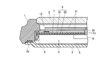
図1は腕時計の要部拡大断面図、図2は、図1の腕時計の文字板およびソーラセル構造体を側面から見た断面図である。
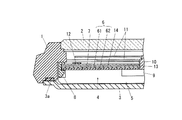
図1において、1は腕時計ケースである。この腕時計ケース1の上面には時計ガラス2が装着され、下面には裏蓋3が防水リング3aを介して取り付けられている。腕時計ケース1の内部には時計モジュール4が収納されている。この時計モジュール4はハウジング5を備えている。このハウジング5の上面にはソーラセル構造体6と化粧板である文字板7とが押え板8によって取り付けられている。文字板7の上面の周縁部には、1時〜12時などを表す数字や図形などの時字(マーク部)12が設けられている。
ハウジング5内にはアナログムーブメント9が設けられている。このアナログムーブメント9の指針軸10は、ソーラセル構造体6および文字板7に形成された貫通孔13を通してその上方に突出し、この突出した指針軸10の上部に時針および分針などの指針11が取り付けられた構造になっている。
[First Embodiment]
The first embodiment will be described below with reference to FIGS.
FIG. 1 is an enlarged cross-sectional view of a main part of the wristwatch, and FIG. 2 is a cross-sectional view of the dial and solar cell structure of the wristwatch of FIG.
In FIG. 1, 1 is a wristwatch case. A
An
ソーラセル構造体6は、図2に示すように、ソーラセル61および支持基板62によって構成されている。支持基板62はソーラセル61の裏側に重ね合わされた状態(当接状態)で配置されている。
ソーラセル61は、特に限定はされないが、同一平面上の位置に1つまたは複数設けられている。支持基板62はソーラセル61を支持するためのものである。この支持基板62には導電パターン(図示せず)が形成され、ソーラセル61は導電パターンを介してハウジング5の内部に配置された二次電池等に接続されている。
The
The
このソーラセル構造体6の表側には文字板7が重ね合わされた状態(当接状態)で配置されている。そして、ソーラセル構造体6と文字板7とは一体化されている。このソーラセル構造体6と文字板7との一体化は次のようにして行われる。
例えば、ソーラセル61を予め支持基板62や文字板7よりも小さく形成しておき、ソーラセル61を支持基板62と文字板7とで挟み込んだ状態で、ソーラセル61の周縁部外方位置で支持基板62と文字板7とを接着剤により接着する。これによって、ソーラセル構造体6と文字板7とが一体化される。
或いは、支持基板62、ソーラセル61および文字板7のうち隣り合うもの同士を接着剤により接着する。これによって、ソーラセル構造体6と文字板7とが一体化される。この場合、ソーラセル61と文字板7との接着にあたっては、光透過性を持つ接着剤を使用することが好ましい。ソーラセル61の表面に接着剤が付着するので、光透過性を持たない接着剤の場合、ソーラセル61への光の到達を阻害するからである。したがって、光透過性を持たない接着剤を使用する場合には、ソーラセル61への光の到達を極力妨げない部分で、ソーラセル61と文字板7との接着を行うことが好ましい。
On the front side of the
For example, the
Alternatively, adjacent ones of the
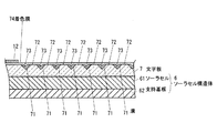
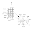
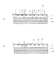
文字板7は、透明または半透明のガラスや合成樹脂からなる板状のもので形成されている。図3は後述の着色膜74を形成する前の文字板7の平面図である。この文字板7の表面には、図3に示すように、断面V字状の溝71が縦横格子状に形成されている。この文字板7における断面V字状の溝71で区画される部分は、平坦部72となっている。この溝71および平坦部72は、文字板7の表面における時字12や表面装飾部以外でソーラセル61を覆っている部分に一様に形成されていることが好ましい。時字12や表面装飾部分は比較的濃色を有しているため、それ自体で、ソーラセル61を覆い隠すことができるからである。
また、文字板7の各断面V字状の溝71内面には光反射被膜73がそれぞれ形成されている。この各光反射被膜73は、アルミニウムやクロムなどの金属からなり、各溝71の内面のみにほぼ均一な膜厚で形成されている。他方、文字板7における平坦部72には光反射被膜73は形成されていない。
また、文字板7の表面には、各溝71および各平坦部72の表面を覆うように光透過性の着色膜74が形成されている。この着色膜74は、例えば白色顔料を含有した樹脂をインク化することによって印刷で形成されている。
The
Further, a
Further, a light-transmitting
なお、ここでは、文字板7の表面に断面V字状の溝71および平坦部72を形成したが、凹部と平坦部72があるパターン模様であればよく、例えば、梨地模様、ストライプ模様、幾何学模様等であってもよい。
また、凹部の断面もV字状に限定されない。例えば、断面は半球状であってもよい。
また、凹部と平坦部72の面積や文字板7の各種寸法(例えば厚さ寸法)は、全体として約50%の光透過、約50%の光反射が得られるように設定することが好ましい。
Here, the
Further, the cross section of the recess is not limited to a V shape. For example, the cross section may be hemispherical.
Moreover, it is preferable to set the area of the recessed part and the
次に、この文字板7の製造方法について、図4を参照して説明する。
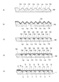
まず、図4(A)に示すように、文字板7の始発部材である光透過性部材700の表面に断面V字状の溝710を縦横に格子状に形成する。その際、特に限定はされないが、側面から見て山と谷が交互に形成されるように溝710の間隔を設定する。
次に、図4(B)に示すように、光透過性部材700の表面にアルミニウムやクロムなどの金属を蒸着して光反射被膜730をほぼ均一な膜厚で形成する。
その後、図4(C)に示すように、山の先端部のみを光反射被膜730とともに研磨作業などによりカットして、山の先端部を平坦面に形成する。これにより、平坦部720が形成され、その平坦部720が表面に露出し、谷の内面のみに光反射被膜730が残る。この平坦部720、谷の内面のみに残った光反射被膜730および谷は最終的にそれぞれ文字板7の平坦部72、光反射被膜73および谷となる(図4(E)参照)。
次に、図4(D)に示すように、光透光性部材700の表面全体に光透過性の着色膜740を形成する。着色膜740の形成は例えば印刷によってなされる。この着色膜740は最終的に文字板7の着色膜74となる(図4(E)参照)。
次に、図4(E)に示すように、光透過性部材700の外周部で上記平坦部720に対応する部分の表面に時字12を印刷する。これによって文字板7が完成する。
その後に、ソーラセル構造体6と文字板7とを一体化する。一体化の方法は上述の通りである。これによって、ソーラセル構造体6と文字板7との一体化構造が得られる(図2参照)。
なお、文字板7の製造方法は上記に限定されない。
例えば、光透過性部材700の表面に形成される断面V字状の溝710の間隔を、側面から見て山と谷が交互に形成されるように設定したが、隣り合う溝710同士の間隔を溝幅よりも大きくすることによって、隣り合う溝710同士の間に最初から平坦面が形成されるようにしてもよい。
Next, the manufacturing method of this
First, as shown in FIG. 4A,
Next, as shown in FIG. 4B, a metal such as aluminum or chromium is vapor-deposited on the surface of the
Thereafter, as shown in FIG. 4C, only the tip of the mountain is cut together with the
Next, as shown in FIG. 4D, a light-transmitting
Next, as illustrated in FIG. 4E, the
Thereafter, the
In addition, the manufacturing method of the
For example, although the interval between the
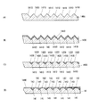
この第1の実施形態によれば、外部光は、図5(A)に示すように、その一部の光が文字板7の各平坦部72をそれぞれ透過してソーラセル61に入射されるので、各ソーラセル61の発電作用により入射された光のエネルギーが電気エネルギーに変換され、この変換された電気エネルギーに係る電気信号が導電パターンを介してハウジング5の内部に配置された二次電池等に給電されて充電または蓄電することができる。
また、外部光は、図5(A)に示すように、その一部の光が文字板7の溝71の光反射被膜73で反射されて外部から視認される。この場合、光反射被膜73が金属被膜で形成されているので、光反射被膜73の部分が着色膜74を介して金属色(本実施形態の場合、金属色と着色膜の色とが混ざり合った色)として視認されるために、高級感が醸し出されることになる。また、見る角度、光の当たる角度によってその光り方が変化するので、装飾性の高い製品が実現できる。
また、外部光でソーラセル61に到達した光の一部は、図5(B)に示すように、ソーラセル61の表面で反射するが、このうち文字板7の溝71に向かう光は光反射被膜73で反射され、文字板7の外部には出射されない(すなわち光反射皮膜73で遮光される)ので、外部からは視認しにくくなる。したがって、外部から見てソーラセル61の表面の地色である濃紫色が目立たないものとなる。
さらに、この第1の実施形態によれば、文字板7とソーラセル61とが接着によって一体化されているので、組立時に文字板7とソーラセル61との間隔調整が不要となり、組立が容易となる。
According to the first embodiment, as shown in FIG. 5A, a part of the external light passes through each
Further, as shown in FIG. 5A, a part of the external light is reflected by the
Further, as shown in FIG. 5 (B), a part of the light reaching the
Furthermore, according to the first embodiment, since the
[第2の実施形態]
次に、図6〜図8を参照して、第2の実施形態について説明する。
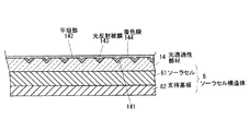
図6は、第2の実施形態に係る腕時計の要部拡大断面図、図7は、図6の腕時計の文字板、光透過性部材およびソーラセル構造体を側面から見た断面図である。
この第2の実施形態の腕時計と第1の実施形態の腕時計とでは以下の点で異なっている。
第1に、この第2の実施形態の腕時計では、光透過性の文字板7とソーラセル構造体6とが別体となっており、ソーラセル構造体6は、文字板7と同様の別の光透過性部材14と一体となっている。
第2に、第2の実施形態の腕時計では、文字板7の表面にV字状の溝71、光反射被膜73および着色膜74が形成されていない。代わりに、光透過性部材14の表面に、V字状の溝71、平坦部72、光反射被膜73および着色膜74と同様のV字状の溝141、平坦部142、光反射被膜143および着色膜144が形成されている。ただし、着色膜については、文字板7の表面にも着色膜が形成されていてもよいし、光透過性部材14の表面ではなく文字板7の表面にだけ着色膜が形成されていてもよい。
なお、第2の実施形態のその他の部分は第1の実施形態とほぼ同じであるので、図面に同一符号を付し、その説明は適宜省略する。
[Second Embodiment]
Next, a second embodiment will be described with reference to FIGS.
6 is an enlarged cross-sectional view of a main part of the wristwatch according to the second embodiment, and FIG. 7 is a cross-sectional view of the dial, light transmitting member, and solar cell structure of the wristwatch of FIG.
The wristwatch according to the second embodiment is different from the wristwatch according to the first embodiment in the following points.
First, in the wristwatch of the second embodiment, the light-transmitting
Secondly, in the wristwatch of the second embodiment, the V-shaped
In addition, since the other part of 2nd Embodiment is as substantially the same as 1st Embodiment, the same code | symbol is attached | subjected to drawing and the description is abbreviate | omitted suitably.
次に、ソーラセル構造体6の光透過性部材14の製造方法について、図8を参照して説明する。
まず、図8(A)に示すように、始発部材である光透過性部材1400の表面に断面V字状の溝1410を縦横に格子状に形成する。その際、特に限定はされないが、側面から見て山と谷が交互に形成されるように溝1410の間隔を設定する。
次に、図8(B)に示すように、光透過性部材1400の表面にアルミニウムやクロムなどの金属を蒸着して光反射被膜1430をほぼ均一な膜厚で形成する。
その後、図8(C)に示すように、山の先端部のみを光反射被膜1430とともに研磨作業などによりカットして、山の先端部を平坦面に形成する。これにより、平坦部1420が形成され、その平坦部1420が表面に露出し、谷の内面のみに光反射被膜1430が残る。この平坦部1420、谷の内面のみに残った光反射被膜1430および谷は最終的にそれぞれ光透過性部材14の平坦部142、光反射被膜143および谷となる(図8(D)参照)。
次に、光透光性部材1400の表面全体に光透過性の着色膜1440を形成する。着色膜1440の形成は例えば印刷によってなされる。この着色膜1440は、図8(D)に示すように、最終的に光透過性部材14の着色膜144となる。
その後に、光透過性部材14とソーラセル構造体6とを一体化する。
Next, a method for manufacturing the
First, as shown in FIG. 8A,
Next, as shown in FIG. 8B, a metal such as aluminum or chromium is vapor-deposited on the surface of the
Thereafter, as shown in FIG. 8C, only the tip of the mountain is cut together with the
Next, a light-transmitting
Thereafter, the
この光透過性部材14とソーラセル構造体6との一体化は次のようにして行われる。
例えば、ソーラセル61を予め支持基板62や光透過性部材14よりも小さく形成しておき、ソーラセル61を支持基板62と光透過性部材14とで挟み込んだ状態で、ソーラセル61の周縁部外方位置で支持基板62と光透過性部材14とを接着剤により接着する。これによって、光透過性部材14とソーラセル構造体6とが一体化される。
或いは、支持基板62、ソーラセル61および光透過性部材14のうち隣り合うもの同士を接着剤により接着する。これによって、ソーラセル構造体6と光透過性部材14とが一体化される。この場合、ソーラセル61と光透過性部材14との接着にあたっては、光透過性を持つ接着剤を使用することが好ましい。ソーラセル61の表面に接着剤が付着するので、光透過性を持たない接着剤の場合、ソーラセル61への光の到達を阻害するからである。したがって、光透過性を持たない接着剤を使用する場合には、ソーラセル61への光の到達を極力妨げない部分で、ソーラセル61と光透過性部材14との接着を行うことが好ましい。
The
For example, the
Alternatively, adjacent ones of the
なお、光透過性部材14の製造方法は上記に限定されない。
例えば、光透過性部材1400の表面に形成される断面V字状の溝1410の間隔を、側面から見て山と谷が交互に形成されるように設定したが、隣り合う溝1410同士の間隔を溝幅よりも大きくすることによって、隣り合う溝1410同士の間に最初から平坦面が形成されるようにしてもよい。
In addition, the manufacturing method of the
For example, the interval between the
この第2の実施形態によれば、外部光は、その一部の光が光透過性部材14の各平坦部142をそれぞれ透過してソーラセル61に入射されるので、各ソーラセル61の発電作用により入射された光のエネルギーが電気エネルギーに変換され、この変換された電気エネルギーに係る電気信号が導電パターンを介してハウジング5の内部に配置された二次電池等に給電されて充電または蓄電することができる。
また、外部光は、その一部の光が文字板7の溝141の光反射被膜143で反射されて外部から視認される。この場合、光反射被膜143が金属被膜で形成されているので、光反射被膜143の部分が着色膜144を介して金属色(本実施形態の場合、金属色と着色膜の色とが混ざり合った色)として視認されるために、高級感が醸し出されることになる。また、見る角度、光の当たる角度によってその光り方が変化するので、装飾性の高い製品が実現できる。
また、外部光でソーラセル61に到達した光の一部は、ソーラセル61の表面で反射するが、このうち光透過性部材14の溝141に向かう光は光反射被膜143で反射され、光透過性部材14および文字板7の外部には出射されない(すなわち光反射皮膜143で遮光される)ので、外部からは視認しにくくなる。したがって、外部から見てソーラセル61の表面の地色である濃紫色が目立たないものとなる。
さらに、この第2の実施形態によれば、光透過性部材14とソーラセル61とが接着によって一体化されているので、組立時に光透過性部材14とソーラセル61との間隔調整が不要となり組立が容易となる。
また、この第2の実施形態によれば、光透過性部材14が文字板7を兼ねていないので、文字板7の無い表示装置にも容易に組み込むことが可能である。
According to the second embodiment, a part of the external light passes through each
In addition, a part of the external light is reflected by the
Further, a part of the light reaching the
Furthermore, according to the second embodiment, since the
Further, according to the second embodiment, since the
1 腕時計ケース
2 時計ガラス
6 ソーラセル構造体
61 ソーラセル
62 支持基板
7 文字板
71 溝
72 平坦部
73 光反射被膜
74 着色膜
14 光透過性部材
141 溝
142 平坦部
143 光反射被膜
144 着色膜
DESCRIPTION OF SYMBOLS 1
Claims (5)
このステップにより溝が形成された光透過性部材の表面に光反射被膜を予め定められている膜厚で形成するステップと、
このステップにより光反射被膜が形成された光透過性部材の表面をカットして、前記溝の谷部分を残すとともに、この残された谷部分によって区画された部分を平坦面に形成して該平坦面の前記光反射皮膜を除去し、前記谷部分の内面のみに光反射被膜を残すステップと、
このステップにより得られた光透光性部材の裏面側にソーラセルおよび該ソーラセルを支持する支持基板を配置して接着によって一体化するステップと、
を備えていることを特徴とする表示装置の製造方法。 A method of manufacturing a display device including a solar cell, wherein a groove having a V-shaped cross section is formed on a surface of a light-transmitting member in a lattice shape vertically and horizontally;
Forming a light reflecting film with a predetermined film thickness on the surface of the light transmissive member in which grooves are formed by this step;
By this step, the surface of the light-transmitting member on which the light reflecting film is formed is cut to leave the groove valley portion, and a portion defined by the remaining valley portion is formed on a flat surface to form the flat surface. Removing the light reflecting coating on the surface and leaving the light reflecting coating only on the inner surface of the valley portion;
Arranging a solar cell and a support substrate supporting the solar cell on the back side of the light transmissive member obtained by this step and integrating them by bonding;
A method for manufacturing a display device, comprising:
Priority Applications (1)
| Application Number | Priority Date | Filing Date | Title |
|---|---|---|---|
| JP2009260793A JP2011106908A (en) | 2009-11-16 | 2009-11-16 | Display device and wrist watch |
Applications Claiming Priority (1)
| Application Number | Priority Date | Filing Date | Title |
|---|---|---|---|
| JP2009260793A JP2011106908A (en) | 2009-11-16 | 2009-11-16 | Display device and wrist watch |
Publications (1)
| Publication Number | Publication Date |
|---|---|
| JP2011106908A true JP2011106908A (en) | 2011-06-02 |
Family
ID=44230558
Family Applications (1)
| Application Number | Title | Priority Date | Filing Date |
|---|---|---|---|
| JP2009260793A Pending JP2011106908A (en) | 2009-11-16 | 2009-11-16 | Display device and wrist watch |
Country Status (1)
| Country | Link |
|---|---|
| JP (1) | JP2011106908A (en) |
Cited By (3)
| Publication number | Priority date | Publication date | Assignee | Title |
|---|---|---|---|---|
| EP2796946A1 (en) * | 2013-04-24 | 2014-10-29 | ETA SA Manufacture Horlogère Suisse | Timepiece including a digital device for displaying information |
| CN111722518A (en) * | 2020-06-24 | 2020-09-29 | Oppo广东移动通信有限公司 | watch |
| JP2021067591A (en) * | 2019-10-25 | 2021-04-30 | シチズン時計株式会社 | Timepiece with solar battery and method of manufacturing timepiece with solar battery |
-
2009
- 2009-11-16 JP JP2009260793A patent/JP2011106908A/en active Pending
Cited By (4)
| Publication number | Priority date | Publication date | Assignee | Title |
|---|---|---|---|---|
| EP2796946A1 (en) * | 2013-04-24 | 2014-10-29 | ETA SA Manufacture Horlogère Suisse | Timepiece including a digital device for displaying information |
| JP2021067591A (en) * | 2019-10-25 | 2021-04-30 | シチズン時計株式会社 | Timepiece with solar battery and method of manufacturing timepiece with solar battery |
| JP7236980B2 (en) | 2019-10-25 | 2023-03-10 | シチズン時計株式会社 | SOLAR BATTERY WATCH, MANUFACTURING METHOD OF SOLAR BATTERY WATCH |
| CN111722518A (en) * | 2020-06-24 | 2020-09-29 | Oppo广东移动通信有限公司 | watch |
Similar Documents
| Publication | Publication Date | Title |
|---|---|---|
| US8787120B2 (en) | Exterior element for a wristwatch | |
| CN102947764B (en) | Watch display plate | |
| US6208591B1 (en) | Luminescent device, timepiece, electronic apparatus and method for manufacturing luminescent device | |
| JP4922562B2 (en) | Clock display board | |
| JP5946390B2 (en) | Electronic watch with solar cell | |
| JP2012122808A (en) | Dial for timepiece, and the timepiece | |
| JP2011106908A (en) | Display device and wrist watch | |
| JP4551678B2 (en) | Cell phone clock | |
| JP2008051517A (en) | Dial for timepiece, and watch equipped therewith | |
| JP5104982B2 (en) | Electronics | |
| JPH10253773A (en) | Covering member for covering upper surface of solar cell, electronic device and watch having the same | |
| JP4685435B2 (en) | Clock with solar battery | |
| JP2006292427A (en) | Decorative plate and electronic equipment | |
| JP5946368B2 (en) | Electronic watch with solar cell | |
| JP2002221581A (en) | Electronic apparatus with solar cell | |
| JP5139862B2 (en) | Display board for solar cell equipment | |
| JP5412312B2 (en) | Dial and clock | |
| JP4398760B2 (en) | Clock with solar battery | |
| JPH1123730A (en) | Covering member for covering upper surface of solar cell, electronic device and watch having the same | |
| JP7712886B2 (en) | Dials and Clocks | |
| JP2003066162A (en) | Solar dial for timepiece | |
| JP3691334B2 (en) | Solar powered watch | |
| JP2010203817A (en) | Pointer type timepiece | |
| JPH10282253A (en) | Dial for solar timpiece, and solar timepiece | |
| JP2023117106A (en) | watches and dials |