JP6444857B2 - Non-invasive measurement of analyte concentration using a fiberless transmission and reflection probe - Google Patents
Non-invasive measurement of analyte concentration using a fiberless transmission and reflection probe Download PDFInfo
- Publication number
- JP6444857B2 JP6444857B2 JP2015504720A JP2015504720A JP6444857B2 JP 6444857 B2 JP6444857 B2 JP 6444857B2 JP 2015504720 A JP2015504720 A JP 2015504720A JP 2015504720 A JP2015504720 A JP 2015504720A JP 6444857 B2 JP6444857 B2 JP 6444857B2
- Authority
- JP
- Japan
- Prior art keywords
- target area
- fluid
- target
- analyte
- optical rod
- Prior art date
- Legal status (The legal status is an assumption and is not a legal conclusion. Google has not performed a legal analysis and makes no representation as to the accuracy of the status listed.)
- Expired - Fee Related
Links
- 238000005259 measurement Methods 0.000 title claims description 59
- 239000012491 analyte Substances 0.000 title claims description 54
- 239000000523 sample Substances 0.000 title claims description 53
- 230000005540 biological transmission Effects 0.000 title claims description 12
- 230000003287 optical effect Effects 0.000 claims description 68
- 230000005855 radiation Effects 0.000 claims description 35
- 239000012530 fluid Substances 0.000 claims description 33
- 238000001514 detection method Methods 0.000 claims description 30
- 238000000034 method Methods 0.000 claims description 21
- 239000008280 blood Substances 0.000 claims description 19
- 210000004369 blood Anatomy 0.000 claims description 19
- 238000010521 absorption reaction Methods 0.000 claims description 16
- 239000011159 matrix material Substances 0.000 claims description 15
- 230000005670 electromagnetic radiation Effects 0.000 claims description 9
- 230000010349 pulsation Effects 0.000 claims description 5
- 239000000835 fiber Substances 0.000 claims description 3
- 238000004891 communication Methods 0.000 claims description 2
- 210000001519 tissue Anatomy 0.000 description 10
- WQZGKKKJIJFFOK-GASJEMHNSA-N Glucose Natural products OC[C@H]1OC(O)[C@H](O)[C@@H](O)[C@@H]1O WQZGKKKJIJFFOK-GASJEMHNSA-N 0.000 description 6
- 239000008103 glucose Substances 0.000 description 6
- 238000012360 testing method Methods 0.000 description 6
- 230000006835 compression Effects 0.000 description 5
- 238000007906 compression Methods 0.000 description 5
- 238000005516 engineering process Methods 0.000 description 5
- XAGFODPZIPBFFR-UHFFFAOYSA-N aluminium Chemical compound [Al] XAGFODPZIPBFFR-UHFFFAOYSA-N 0.000 description 4
- 229910052782 aluminium Inorganic materials 0.000 description 4
- 239000006185 dispersion Substances 0.000 description 4
- NOESYZHRGYRDHS-UHFFFAOYSA-N insulin Chemical compound N1C(=O)C(NC(=O)C(CCC(N)=O)NC(=O)C(CCC(O)=O)NC(=O)C(C(C)C)NC(=O)C(NC(=O)CN)C(C)CC)CSSCC(C(NC(CO)C(=O)NC(CC(C)C)C(=O)NC(CC=2C=CC(O)=CC=2)C(=O)NC(CCC(N)=O)C(=O)NC(CC(C)C)C(=O)NC(CCC(O)=O)C(=O)NC(CC(N)=O)C(=O)NC(CC=2C=CC(O)=CC=2)C(=O)NC(CSSCC(NC(=O)C(C(C)C)NC(=O)C(CC(C)C)NC(=O)C(CC=2C=CC(O)=CC=2)NC(=O)C(CC(C)C)NC(=O)C(C)NC(=O)C(CCC(O)=O)NC(=O)C(C(C)C)NC(=O)C(CC(C)C)NC(=O)C(CC=2NC=NC=2)NC(=O)C(CO)NC(=O)CNC2=O)C(=O)NCC(=O)NC(CCC(O)=O)C(=O)NC(CCCNC(N)=N)C(=O)NCC(=O)NC(CC=3C=CC=CC=3)C(=O)NC(CC=3C=CC=CC=3)C(=O)NC(CC=3C=CC(O)=CC=3)C(=O)NC(C(C)O)C(=O)N3C(CCC3)C(=O)NC(CCCCN)C(=O)NC(C)C(O)=O)C(=O)NC(CC(N)=O)C(O)=O)=O)NC(=O)C(C(C)CC)NC(=O)C(CO)NC(=O)C(C(C)O)NC(=O)C1CSSCC2NC(=O)C(CC(C)C)NC(=O)C(NC(=O)C(CCC(N)=O)NC(=O)C(CC(N)=O)NC(=O)C(NC(=O)C(N)CC=1C=CC=CC=1)C(C)C)CC1=CN=CN1 NOESYZHRGYRDHS-UHFFFAOYSA-N 0.000 description 4
- 230000008569 process Effects 0.000 description 4
- 229920001169 thermoplastic Polymers 0.000 description 4
- 102000001554 Hemoglobins Human genes 0.000 description 3
- 108010054147 Hemoglobins Proteins 0.000 description 3
- VYPSYNLAJGMNEJ-UHFFFAOYSA-N Silicium dioxide Chemical compound O=[Si]=O VYPSYNLAJGMNEJ-UHFFFAOYSA-N 0.000 description 3
- 238000010586 diagram Methods 0.000 description 3
- 239000011521 glass Substances 0.000 description 3
- 230000002452 interceptive effect Effects 0.000 description 3
- 238000012545 processing Methods 0.000 description 3
- 238000002310 reflectometry Methods 0.000 description 3
- 102000004877 Insulin Human genes 0.000 description 2
- 108090001061 Insulin Proteins 0.000 description 2
- 230000008901 benefit Effects 0.000 description 2
- 230000008859 change Effects 0.000 description 2
- HVYWMOMLDIMFJA-DPAQBDIFSA-N cholesterol Chemical compound C1C=C2C[C@@H](O)CC[C@]2(C)[C@@H]2[C@@H]1[C@@H]1CC[C@H]([C@H](C)CCCC(C)C)[C@@]1(C)CC2 HVYWMOMLDIMFJA-DPAQBDIFSA-N 0.000 description 2
- 238000001746 injection moulding Methods 0.000 description 2
- 229940125396 insulin Drugs 0.000 description 2
- 210000002977 intracellular fluid Anatomy 0.000 description 2
- 238000012544 monitoring process Methods 0.000 description 2
- 239000013307 optical fiber Substances 0.000 description 2
- 229920003229 poly(methyl methacrylate) Polymers 0.000 description 2
- 239000004926 polymethyl methacrylate Substances 0.000 description 2
- 239000010453 quartz Substances 0.000 description 2
- 230000001360 synchronised effect Effects 0.000 description 2
- SNICXCGAKADSCV-JTQLQIEISA-N (-)-Nicotine Chemical compound CN1CCC[C@H]1C1=CC=CN=C1 SNICXCGAKADSCV-JTQLQIEISA-N 0.000 description 1
- 206010005746 Blood pressure fluctuation Diseases 0.000 description 1
- 239000004793 Polystyrene Substances 0.000 description 1
- 230000008033 biological extinction Effects 0.000 description 1
- 235000012000 cholesterol Nutrition 0.000 description 1
- 229940107161 cholesterol Drugs 0.000 description 1
- 239000011248 coating agent Substances 0.000 description 1
- 238000000576 coating method Methods 0.000 description 1
- 125000004122 cyclic group Chemical group 0.000 description 1
- 230000006837 decompression Effects 0.000 description 1
- 206010012601 diabetes mellitus Diseases 0.000 description 1
- 238000003745 diagnosis Methods 0.000 description 1
- 201000010099 disease Diseases 0.000 description 1
- 208000037265 diseases, disorders, signs and symptoms Diseases 0.000 description 1
- 229940079593 drug Drugs 0.000 description 1
- 239000003814 drug Substances 0.000 description 1
- 210000000624 ear auricle Anatomy 0.000 description 1
- 210000003722 extracellular fluid Anatomy 0.000 description 1
- 239000005350 fused silica glass Substances 0.000 description 1
- 230000036541 health Effects 0.000 description 1
- 208000015181 infectious disease Diseases 0.000 description 1
- 238000002347 injection Methods 0.000 description 1
- 239000007924 injection Substances 0.000 description 1
- 230000003834 intracellular effect Effects 0.000 description 1
- 230000031700 light absorption Effects 0.000 description 1
- 239000007788 liquid Substances 0.000 description 1
- 230000007246 mechanism Effects 0.000 description 1
- 238000012806 monitoring device Methods 0.000 description 1
- 229960002715 nicotine Drugs 0.000 description 1
- SNICXCGAKADSCV-UHFFFAOYSA-N nicotine Natural products CN1CCCC1C1=CC=CN=C1 SNICXCGAKADSCV-UHFFFAOYSA-N 0.000 description 1
- 230000002093 peripheral effect Effects 0.000 description 1
- 229920000098 polyolefin Polymers 0.000 description 1
- 230000001105 regulatory effect Effects 0.000 description 1
- 230000035945 sensitivity Effects 0.000 description 1
- 238000000926 separation method Methods 0.000 description 1
- 238000007493 shaping process Methods 0.000 description 1
- 238000001228 spectrum Methods 0.000 description 1
- 230000035488 systolic blood pressure Effects 0.000 description 1
- 238000012549 training Methods 0.000 description 1
- 238000012546 transfer Methods 0.000 description 1
- 238000009827 uniform distribution Methods 0.000 description 1
- 210000002700 urine Anatomy 0.000 description 1
Images


Classifications
-
- A—HUMAN NECESSITIES
- A61—MEDICAL OR VETERINARY SCIENCE; HYGIENE
- A61B—DIAGNOSIS; SURGERY; IDENTIFICATION
- A61B5/00—Measuring for diagnostic purposes; Identification of persons
- A61B5/145—Measuring characteristics of blood in vivo, e.g. gas concentration, pH value; Measuring characteristics of body fluids or tissues, e.g. interstitial fluid, cerebral tissue
- A61B5/14532—Measuring characteristics of blood in vivo, e.g. gas concentration, pH value; Measuring characteristics of body fluids or tissues, e.g. interstitial fluid, cerebral tissue for measuring glucose, e.g. by tissue impedance measurement
-
- A—HUMAN NECESSITIES
- A61—MEDICAL OR VETERINARY SCIENCE; HYGIENE
- A61B—DIAGNOSIS; SURGERY; IDENTIFICATION
- A61B5/00—Measuring for diagnostic purposes; Identification of persons
- A61B5/145—Measuring characteristics of blood in vivo, e.g. gas concentration, pH value; Measuring characteristics of body fluids or tissues, e.g. interstitial fluid, cerebral tissue
- A61B5/1455—Measuring characteristics of blood in vivo, e.g. gas concentration, pH value; Measuring characteristics of body fluids or tissues, e.g. interstitial fluid, cerebral tissue using optical sensors, e.g. spectral photometrical oximeters
-
- G—PHYSICS
- G01—MEASURING; TESTING
- G01N—INVESTIGATING OR ANALYSING MATERIALS BY DETERMINING THEIR CHEMICAL OR PHYSICAL PROPERTIES
- G01N21/00—Investigating or analysing materials by the use of optical means, i.e. using sub-millimetre waves, infrared, visible or ultraviolet light
- G01N21/17—Systems in which incident light is modified in accordance with the properties of the material investigated
- G01N21/1717—Systems in which incident light is modified in accordance with the properties of the material investigated with a modulation of one or more physical properties of the sample during the optical investigation, e.g. electro-reflectance
-
- G—PHYSICS
- G01—MEASURING; TESTING
- G01N—INVESTIGATING OR ANALYSING MATERIALS BY DETERMINING THEIR CHEMICAL OR PHYSICAL PROPERTIES
- G01N21/00—Investigating or analysing materials by the use of optical means, i.e. using sub-millimetre waves, infrared, visible or ultraviolet light
- G01N21/17—Systems in which incident light is modified in accordance with the properties of the material investigated
- G01N21/25—Colour; Spectral properties, i.e. comparison of effect of material on the light at two or more different wavelengths or wavelength bands
- G01N21/31—Investigating relative effect of material at wavelengths characteristic of specific elements or molecules, e.g. atomic absorption spectrometry
- G01N21/314—Investigating relative effect of material at wavelengths characteristic of specific elements or molecules, e.g. atomic absorption spectrometry with comparison of measurements at specific and non-specific wavelengths
-
- G—PHYSICS
- G01—MEASURING; TESTING
- G01N—INVESTIGATING OR ANALYSING MATERIALS BY DETERMINING THEIR CHEMICAL OR PHYSICAL PROPERTIES
- G01N21/00—Investigating or analysing materials by the use of optical means, i.e. using sub-millimetre waves, infrared, visible or ultraviolet light
- G01N21/17—Systems in which incident light is modified in accordance with the properties of the material investigated
- G01N21/25—Colour; Spectral properties, i.e. comparison of effect of material on the light at two or more different wavelengths or wavelength bands
- G01N21/31—Investigating relative effect of material at wavelengths characteristic of specific elements or molecules, e.g. atomic absorption spectrometry
- G01N21/35—Investigating relative effect of material at wavelengths characteristic of specific elements or molecules, e.g. atomic absorption spectrometry using infrared light
- G01N21/359—Investigating relative effect of material at wavelengths characteristic of specific elements or molecules, e.g. atomic absorption spectrometry using infrared light using near infrared light
-
- G—PHYSICS
- G01—MEASURING; TESTING
- G01N—INVESTIGATING OR ANALYSING MATERIALS BY DETERMINING THEIR CHEMICAL OR PHYSICAL PROPERTIES
- G01N21/00—Investigating or analysing materials by the use of optical means, i.e. using sub-millimetre waves, infrared, visible or ultraviolet light
- G01N21/17—Systems in which incident light is modified in accordance with the properties of the material investigated
- G01N21/47—Scattering, i.e. diffuse reflection
- G01N21/49—Scattering, i.e. diffuse reflection within a body or fluid
-
- G—PHYSICS
- G01—MEASURING; TESTING
- G01N—INVESTIGATING OR ANALYSING MATERIALS BY DETERMINING THEIR CHEMICAL OR PHYSICAL PROPERTIES
- G01N33/00—Investigating or analysing materials by specific methods not covered by groups G01N1/00 - G01N31/00
- G01N33/48—Biological material, e.g. blood, urine; Haemocytometers
- G01N33/483—Physical analysis of biological material
- G01N33/487—Physical analysis of biological material of liquid biological material
- G01N33/49—Blood
-
- A—HUMAN NECESSITIES
- A61—MEDICAL OR VETERINARY SCIENCE; HYGIENE
- A61B—DIAGNOSIS; SURGERY; IDENTIFICATION
- A61B2560/00—Constructional details of operational features of apparatus; Accessories for medical measuring apparatus
- A61B2560/04—Constructional details of apparatus
- A61B2560/0431—Portable apparatus, e.g. comprising a handle or case
-
- A—HUMAN NECESSITIES
- A61—MEDICAL OR VETERINARY SCIENCE; HYGIENE
- A61B—DIAGNOSIS; SURGERY; IDENTIFICATION
- A61B2562/00—Details of sensors; Constructional details of sensor housings or probes; Accessories for sensors
- A61B2562/02—Details of sensors specially adapted for in-vivo measurements
- A61B2562/0233—Special features of optical sensors or probes classified in A61B5/00
-
- A—HUMAN NECESSITIES
- A61—MEDICAL OR VETERINARY SCIENCE; HYGIENE
- A61B—DIAGNOSIS; SURGERY; IDENTIFICATION
- A61B2562/00—Details of sensors; Constructional details of sensor housings or probes; Accessories for sensors
- A61B2562/14—Coupling media or elements to improve sensor contact with skin or tissue
- A61B2562/146—Coupling media or elements to improve sensor contact with skin or tissue for optical coupling
-
- A—HUMAN NECESSITIES
- A61—MEDICAL OR VETERINARY SCIENCE; HYGIENE
- A61B—DIAGNOSIS; SURGERY; IDENTIFICATION
- A61B5/00—Measuring for diagnostic purposes; Identification of persons
- A61B5/0048—Detecting, measuring or recording by applying mechanical forces or stimuli
- A61B5/0051—Detecting, measuring or recording by applying mechanical forces or stimuli by applying vibrations
-
- A—HUMAN NECESSITIES
- A61—MEDICAL OR VETERINARY SCIENCE; HYGIENE
- A61B—DIAGNOSIS; SURGERY; IDENTIFICATION
- A61B5/00—Measuring for diagnostic purposes; Identification of persons
- A61B5/68—Arrangements of detecting, measuring or recording means, e.g. sensors, in relation to patient
- A61B5/6801—Arrangements of detecting, measuring or recording means, e.g. sensors, in relation to patient specially adapted to be attached to or worn on the body surface
- A61B5/6813—Specially adapted to be attached to a specific body part
- A61B5/6814—Head
- A61B5/6815—Ear
- A61B5/6816—Ear lobe
-
- A—HUMAN NECESSITIES
- A61—MEDICAL OR VETERINARY SCIENCE; HYGIENE
- A61B—DIAGNOSIS; SURGERY; IDENTIFICATION
- A61B5/00—Measuring for diagnostic purposes; Identification of persons
- A61B5/68—Arrangements of detecting, measuring or recording means, e.g. sensors, in relation to patient
- A61B5/6801—Arrangements of detecting, measuring or recording means, e.g. sensors, in relation to patient specially adapted to be attached to or worn on the body surface
- A61B5/6813—Specially adapted to be attached to a specific body part
- A61B5/6825—Hand
- A61B5/6826—Finger
-
- F—MECHANICAL ENGINEERING; LIGHTING; HEATING; WEAPONS; BLASTING
- F04—POSITIVE - DISPLACEMENT MACHINES FOR LIQUIDS; PUMPS FOR LIQUIDS OR ELASTIC FLUIDS
- F04C—ROTARY-PISTON, OR OSCILLATING-PISTON, POSITIVE-DISPLACEMENT MACHINES FOR LIQUIDS; ROTARY-PISTON, OR OSCILLATING-PISTON, POSITIVE-DISPLACEMENT PUMPS
- F04C2270/00—Control; Monitoring or safety arrangements
- F04C2270/04—Force
- F04C2270/041—Controlled or regulated
-
- G—PHYSICS
- G01—MEASURING; TESTING
- G01N—INVESTIGATING OR ANALYSING MATERIALS BY DETERMINING THEIR CHEMICAL OR PHYSICAL PROPERTIES
- G01N21/00—Investigating or analysing materials by the use of optical means, i.e. using sub-millimetre waves, infrared, visible or ultraviolet light
- G01N21/17—Systems in which incident light is modified in accordance with the properties of the material investigated
- G01N21/25—Colour; Spectral properties, i.e. comparison of effect of material on the light at two or more different wavelengths or wavelength bands
- G01N21/31—Investigating relative effect of material at wavelengths characteristic of specific elements or molecules, e.g. atomic absorption spectrometry
- G01N21/314—Investigating relative effect of material at wavelengths characteristic of specific elements or molecules, e.g. atomic absorption spectrometry with comparison of measurements at specific and non-specific wavelengths
- G01N2021/3148—Investigating relative effect of material at wavelengths characteristic of specific elements or molecules, e.g. atomic absorption spectrometry with comparison of measurements at specific and non-specific wavelengths using three or more wavelengths
-
- G—PHYSICS
- G01—MEASURING; TESTING
- G01N—INVESTIGATING OR ANALYSING MATERIALS BY DETERMINING THEIR CHEMICAL OR PHYSICAL PROPERTIES
- G01N21/00—Investigating or analysing materials by the use of optical means, i.e. using sub-millimetre waves, infrared, visible or ultraviolet light
- G01N21/17—Systems in which incident light is modified in accordance with the properties of the material investigated
- G01N21/47—Scattering, i.e. diffuse reflection
- G01N2021/4704—Angular selective
- G01N2021/4709—Backscatter
-
- G—PHYSICS
- G01—MEASURING; TESTING
- G01N—INVESTIGATING OR ANALYSING MATERIALS BY DETERMINING THEIR CHEMICAL OR PHYSICAL PROPERTIES
- G01N21/00—Investigating or analysing materials by the use of optical means, i.e. using sub-millimetre waves, infrared, visible or ultraviolet light
- G01N21/17—Systems in which incident light is modified in accordance with the properties of the material investigated
- G01N21/47—Scattering, i.e. diffuse reflection
- G01N21/4738—Diffuse reflection, e.g. also for testing fluids, fibrous materials
- G01N21/474—Details of optical heads therefor, e.g. using optical fibres
- G01N2021/4742—Details of optical heads therefor, e.g. using optical fibres comprising optical fibres
- G01N2021/475—Bifurcated bundle
-
- G—PHYSICS
- G01—MEASURING; TESTING
- G01N—INVESTIGATING OR ANALYSING MATERIALS BY DETERMINING THEIR CHEMICAL OR PHYSICAL PROPERTIES
- G01N21/00—Investigating or analysing materials by the use of optical means, i.e. using sub-millimetre waves, infrared, visible or ultraviolet light
- G01N21/17—Systems in which incident light is modified in accordance with the properties of the material investigated
- G01N21/47—Scattering, i.e. diffuse reflection
- G01N21/4738—Diffuse reflection, e.g. also for testing fluids, fibrous materials
- G01N21/474—Details of optical heads therefor, e.g. using optical fibres
-
- G—PHYSICS
- G01—MEASURING; TESTING
- G01N—INVESTIGATING OR ANALYSING MATERIALS BY DETERMINING THEIR CHEMICAL OR PHYSICAL PROPERTIES
- G01N2201/00—Features of devices classified in G01N21/00
- G01N2201/02—Mechanical
- G01N2201/022—Casings
- G01N2201/0221—Portable; cableless; compact; hand-held
-
- G—PHYSICS
- G01—MEASURING; TESTING
- G01N—INVESTIGATING OR ANALYSING MATERIALS BY DETERMINING THEIR CHEMICAL OR PHYSICAL PROPERTIES
- G01N2201/00—Features of devices classified in G01N21/00
- G01N2201/06—Illumination; Optics
- G01N2201/063—Illuminating optical parts
- G01N2201/0631—Homogeneising elements
-
- G—PHYSICS
- G01—MEASURING; TESTING
- G01N—INVESTIGATING OR ANALYSING MATERIALS BY DETERMINING THEIR CHEMICAL OR PHYSICAL PROPERTIES
- G01N2201/00—Features of devices classified in G01N21/00
- G01N2201/06—Illumination; Optics
- G01N2201/063—Illuminating optical parts
- G01N2201/0636—Reflectors
Landscapes
- Health & Medical Sciences (AREA)
- Physics & Mathematics (AREA)
- Life Sciences & Earth Sciences (AREA)
- General Health & Medical Sciences (AREA)
- Pathology (AREA)
- Engineering & Computer Science (AREA)
- Chemical & Material Sciences (AREA)
- Spectroscopy & Molecular Physics (AREA)
- Biomedical Technology (AREA)
- Analytical Chemistry (AREA)
- General Physics & Mathematics (AREA)
- Immunology (AREA)
- Biochemistry (AREA)
- Molecular Biology (AREA)
- Biophysics (AREA)
- Optics & Photonics (AREA)
- Veterinary Medicine (AREA)
- Medical Informatics (AREA)
- Hematology (AREA)
- Surgery (AREA)
- Animal Behavior & Ethology (AREA)
- Public Health (AREA)
- Heart & Thoracic Surgery (AREA)
- Ecology (AREA)
- Emergency Medicine (AREA)
- Urology & Nephrology (AREA)
- Food Science & Technology (AREA)
- Medicinal Chemistry (AREA)
- Measurement Of The Respiration, Hearing Ability, Form, And Blood Characteristics Of Living Organisms (AREA)
- Investigating Or Analysing Materials By Optical Means (AREA)
Description
[0001]本開示は、概括的には、生物医学的検査の分野に関する。より厳密には、本開示は、体組織中の分析物の濃度の非侵襲測定のための方法及び装置に関する。 [0001] The present disclosure relates generally to the field of biomedical testing. More precisely, the present disclosure relates to a method and apparatus for non-invasive measurement of the concentration of an analyte in body tissue.
[0002]血糖濃度の非侵襲的な診断及び測定は、過去20年間の間に、糖尿病が特に全体としての肥満人口の増加に伴って流行病として出現してきたせいで、非常に大きな注目を集めるようになってきた。血糖の非侵襲的な測定は、検査頻度増加の実現性を提供し、ひいてはインスリン投与量の付随調節を通じたより綿密な血糖濃度制御を可能にする。非侵襲検出技法は、更に、インスリン投与を監視及び調整するための可搬式閉ループシステムの実現性を提供する。これらの有望な利点が、非侵襲糖監視機器の商業化における多大な関心へとつながっていった。 [0002] Non-invasive diagnosis and measurement of blood glucose concentration has received tremendous attention over the past two decades, especially because diabetes has emerged as an epidemic with an increase in the overall obese population. It has become like this. Non-invasive measurement of blood glucose provides the feasibility of increasing test frequency and thus allows more precise control of blood glucose concentration through concomitant adjustment of insulin dosage. Non-invasive detection techniques further provide the feasibility of a portable closed loop system for monitoring and regulating insulin administration. These promising advantages have led to great interest in the commercialization of non-invasive sugar monitoring devices.
[0003]現在、血糖測定用の全ての入手可能な可搬式エンドユーザー機器は、血液試料を得るために指先を穿刺することが必要である。次いで血液試料を、糖濃度を指示する検査条片の上に置く。これらの機器は、非常にコンパクトでかなり正確であるが、血液試料を得るために指先を穿刺するというのは不便で、痛く、感染の危険性がある。血糖を測定するための非侵襲機器は今のところ商業的に入手可能ではない。 [0003] Currently, all available portable end-user devices for blood glucose measurement require puncturing the fingertip to obtain a blood sample. The blood sample is then placed on a test strip that indicates the sugar concentration. Although these devices are very compact and fairly accurate, it is inconvenient, painful and risk of infection to puncture a fingertip to obtain a blood sample. Non-invasive devices for measuring blood glucose are not currently commercially available.
[0004]近赤外線エネルギースペクトル―大凡650nm乃至2700nm―の光放射の組織吸収を測定することによって血糖濃度を非侵襲的に測定するべく数々の試みがなされてきた。ここにそっくりそのまま参考文献として援用されるHarjunmaaらへの米国特許第5,099,123号は、混濁したマトリクス即ち体液及び体組織中の分析物濃度の測定のための平衡差(又はOptical Bridge(商標))法を開示している。方法は、標的分析物への吸収が高い主波長と平衡プロセスを使用して選択されている波長であって標的分析物に吸収されない(又は吸収が遥かに少ない)基準波長の2つの波長を利用する。2つの波長は、背景マトリクスに実質的に同じ吸光係数を有するように選択されている。2つの波長を備える放射線ビームが交番式に試料組織マトリクスへ浴びせられると、波長交番と同期する交番信号が、マトリクスによって透過された放射線又は後方散乱した放射線を測定する信号検出器に記録される。交番信号の振幅は試料マトリクス中の標的分析物の濃度に比例する。測定時、Optical Bridge平衡プロセスを使用して、分析物不在下では検出器信号が原則的にゼロになるように2つの交番波長及びそれらの相対強度が変えられる。つまりは、Optical Bridgeは、2つの近赤外線波長を使用して、分析物濃度がなおいっそう視認し易くなるように背景吸収を「空化(null out)」する。 [0004] Numerous attempts have been made to non-invasively measure blood glucose concentrations by measuring tissue absorption of light radiation in the near infrared energy spectrum—approximately 650 nm to 2700 nm. U.S. Pat. No. 5,099,123 to Harjunmaa et al., Which is hereby incorporated by reference in its entirety, describes an equilibrium difference (or Optical Bridge ( Trademark)) law. The method utilizes two wavelengths of a dominant wavelength that is highly absorbed into the target analyte and a reference wavelength that is selected using an equilibrium process and is not absorbed by the target analyte (or much less absorbed). To do. The two wavelengths are selected to have substantially the same extinction coefficient in the background matrix. When a radiation beam with two wavelengths is alternately applied to the sample tissue matrix, an alternating signal synchronized with the wavelength alternating is recorded in a signal detector that measures the radiation transmitted by the matrix or the backscattered radiation. The amplitude of the alternating signal is proportional to the concentration of the target analyte in the sample matrix. During measurement, an optical bridge equilibrium process is used to change the two alternating wavelengths and their relative intensities so that in the absence of analyte, the detector signal is essentially zero. That is, Optical Bridge uses two near-infrared wavelengths to “null out” background absorption so that the analyte concentration is even more visible.
[0005]その後を受け、ここに参考文献として援用される米国特許第5,178,142号の中で、Harjunmaaらは、組織への機械的圧力を変えることによって組織マトリクスの細胞外対細胞内液比を変化させ、試料中に存在する分析物が最小レベルであるときの透過/反射信号をゼロ化する(平衡させる)方法を開示している。 [0005] In US Pat. No. 5,178,142, which was subsequently incorporated herein by reference, Harjunmaa et al. Described the extracellular versus intracellular of the tissue matrix by altering the mechanical pressure on the tissue. Disclosed is a method for changing the liquid ratio and nulling (equilibrium) the transmission / reflection signal when the analyte present in the sample is at a minimum level.
[0006]ここに参考文献として援用される米国特許第7,003,337号の中で、Harjunmaaらは、試料内の標的分析物を含有する流体の量を別の放射線(例えばヘモグロビンによって吸収される緑色光など)を使用して連続推定すること、そして試料検出器の出力を流体体積推定と組み合わせて分析物濃度を計算すること、を開示している。また、同じくここに参考文献として援用される米国特許出願第11/526,564号の中で、Harjunmaaらは、使用中にレーザー波長をチューニングするのではなしに3つの固定波長レーザーダイオードを使用して放射線ビームを発生させる方法を開示している。 [0006] In US Pat. No. 7,003,337, incorporated herein by reference, Harjunmaa et al. Quantitate the amount of fluid containing a target analyte in a sample by another radiation (eg, hemoglobin absorbed). Continuous estimation using a green light, etc.) and combining the output of the sample detector with the fluid volume estimation to calculate the analyte concentration. Also, in U.S. Patent Application No. 11 / 526,564, also incorporated herein by reference, Harjunmaa et al. Uses three fixed wavelength laser diodes rather than tuning the laser wavelength during use. A method for generating a radiation beam is disclosed.
[0007]他の関連特許には、米国特許第5,112,124号、同第5,137,023号、同第5,183,042号、同第5,277,181号、及び同第5,372,135号が含まれ、それら特許の各々を参考文献としてここにそっくりそのまま援用する。 [0007] Other related patents include US Pat. Nos. 5,112,124, 5,137,023, 5,183,042, 5,277,181, and No. 5,372,135, each of which is incorporated herein by reference in its entirety.
[0008]本開示は、ファイバー無し透過反射型プローブを使用して試料中の標的分析物の濃度を非侵襲的に測定するための方法及び装置を記載している。本開示の第1の態様は、標的分析物の量を測定するために標的領域を非侵襲的に調べるための例示的な装置であり、装置は、異なった波長を有している少なくとも2つの反復する放射期間を含む組み合わされた電磁放射線ビームを生成するための源を備えており、当該波長の少なくとも2つは標的分析物について異なった吸収係数を有している。装置は、更に、標的領域によって後方散乱した放射線の一部を検出するように配列されている検出器であって、2つの反復する放射期間の各期間における組み合わされたビームの検出強度に比例する出力信号を生成する検出器と、電磁放射線ビームを標的領域へ方向付けるとともに後方散乱光を検出器へ導くためのファイバー無し透過反射型プローブと、を備えており、当該ファイバー無し透過反射型プローブは、内反射面を有するテーパの付いた管状ハウジングと、外反射面を有する円筒状光学ロッドと、放射線ビームを標的領域へ透過させる検出窓と、を備えている。 [0008] This disclosure describes a method and apparatus for non-invasively measuring the concentration of a target analyte in a sample using a fiberless transmission and reflection probe. A first aspect of the present disclosure is an exemplary apparatus for non-invasively examining a target area to measure the amount of a target analyte, the apparatus comprising at least two having different wavelengths A source is provided for generating a combined electromagnetic radiation beam that includes repeated radiation periods, wherein at least two of the wavelengths have different absorption coefficients for the target analyte. The apparatus is further a detector arranged to detect a portion of the radiation backscattered by the target area, proportional to the detected intensity of the combined beam in each of two repeated radiation periods. A detector that generates an output signal, and a fiberless transmission and reflection probe for directing an electromagnetic radiation beam to a target area and directing backscattered light to the detector, the fiberless transmission and reflection probe A tapered tubular housing having an inner reflective surface, a cylindrical optical rod having an outer reflective surface, and a detection window for transmitting the radiation beam to the target area.
[0009]本開示の別の態様は、試料の特性を測定するための例示的な透過反射型プローブにおいて、試料を照射させる検出窓と、検出窓に垂直に配置されている外反射面を有する光学ロッドと、光学ロッドの周りに配置されている内反射面を有するテーパの付いた管状ハウジングと、試料を照射するための少なくとも1つの光源と、試料によって後方散乱した光を検出するための、光学ロッドの近位端に配置されている検出器と、を含んでいる透過反射型プローブである。 [0009] Another aspect of the present disclosure is an exemplary transflective probe for measuring a property of a sample, including a detection window that illuminates the sample, and an external reflection surface that is disposed perpendicular to the detection window An optical rod, a tapered tubular housing having an inner reflective surface disposed around the optical rod, at least one light source for illuminating the sample, and for detecting light backscattered by the sample; And a detector disposed at the proximal end of the optical rod.
[0010]本開示の更に別の態様は、標的分析物の量を測定するために標的領域を非侵襲的に調べる例示的な方法において、内反射面を有するテーパの付いた管状ハウジングと、検出窓と、自身に垂直に配置されている外反射面を有する光学ロッドと、を備えるファイバー無し透過反射型プローブを提供する段階を備えている方法である。方法は、更に、少なくとも2つの時分割成分から成る放射線ビームを生成するための2つの異なった波長で作動する少なくとも2つの光源を提供する段階と、放射線ビームを、管状ハウジングの内面及び光学ロッドの外面で反射させることによって、標的領域へ透過させる段階と、標的領域からの後方散乱ビームを、光学ロッドの内面で反射させることによって、検出器へ導く段階と、後方散乱ビームを検出し標的領域による2つの波長の差分吸収を指し示す出力信号を発生させる検出器を提供する段階と、を含んでいる。 [0010] Yet another aspect of the present disclosure relates to a tapered tubular housing having an internal reflective surface and detection in an exemplary method for non-invasively examining a target region to measure the amount of a target analyte. Providing a fiberless transmission and reflection probe comprising a window and an optical rod having an outer reflective surface disposed perpendicular to the window. The method further comprises providing at least two light sources operating at two different wavelengths to generate a radiation beam composed of at least two time-division components, and the radiation beam is connected to the inner surface of the tubular housing and the optical rod. Reflecting to the target area by reflecting on the outer surface, directing the backscattered beam from the target area to the detector by reflecting on the inner surface of the optical rod, and detecting the backscattered beam by the target area Providing a detector that generates an output signal indicative of differential absorption of the two wavelengths.
[0011]以上の概括的な説明及び次に続く詳細な説明はどちらも、例示としてであり、解説のみが目的であって、特許請求されている発明を限定するものではない、ということを理解されたい。 [0011] It is understood that both the foregoing general description and the following detailed description are exemplary only and are intended for purposes of illustration only and are not intended to limit the claimed invention. I want to be.
[0012]本明細書に組み入れられその一部を構成している添付図面は、本発明の実施形態を描いており、説明と一体で、本発明の各種態様の原理を解説するべく供されている。 [0012] The accompanying drawings, which are incorporated in and constitute a part of this specification, illustrate embodiments of the invention and, together with the description, serve to explain the principles of the various aspects of the invention. Yes.
[0018]これより本開示に準拠する実施形態を詳細に参照してゆくが、それら実施形態の例が添付図面に描かれている。可能である場合にはいつも図面全体を通して同じ部分又は類似部分を指すのに同じ符号を使用してゆく。 [0018] Reference will now be made in detail to embodiments consistent with the present disclosure, examples of which are illustrated in the accompanying drawings. Wherever possible, the same reference numbers will be used throughout the drawings to refer to the same or like parts.
[0019]或る例示としての実施形態では、ファイバー無し透過反射型プローブを備える光学システムが、試料マトリクス内の流体中の標的分析物の濃度を測定するのに使用されている。分析物濃度は、Optical Bridge(商標)技術を使用して開発された可搬式機器を使用して測定され分析される。本開示の実施形態及びOptical Bridge(商標)技術によれば、分析物濃度の非侵襲光学測定が、「主」波長(λ0)と「基準」波長(λ1)と副波長λ2の間を特定の周波数で交番する電磁放射線ビームを使用して遂行される。λ0は高分析物吸収を実現するように選択され、λ1は最小分析物吸収を有するように選択されている。Optical Bridge(商標)平衡段階時、λ1は、血液無し組織への吸収がλ0と同じになるように調節される。副波長λ2は、流体の或る成分への高い吸収を有するように選択され、試料マトリクスの流体含量の推定を提供するのに使用される。本開示の或る例示としての実施形態では、ファイバー無し透過反射型プローブは、血液(即ち流体)中の糖(即ち標的分析物)の濃度を測定するのに使用されている。その様な実施形態では、λ0は約1620nmとなるように選択され、λ1は約1380nmとなるように選択されており、それらは近赤外線エネルギースペクトルに入っている。副波長λ2は、ヘモグロビンについての等吸収波長である約525nmとなるように選択されており、血液に対する優れた感度を提供する。1つのその様な実施形態では、3つの波長λ0、λ1、及びλ2は、それぞれ、1620+/−20nm、1380+/−20nm、及び525+/−20nmである。電磁放射線ビームは、100Hzの周波数で交番する3つの異なった波長(λ0、λ1、及びλ2)の時分割成分から成る。別の実施形態では、一部又は全部の波長は常時オンになっており、即ち、それらは交番制ではない。一部の特定の実施形態では、信号のその波長成分への分離は、検出器又はプロセッサによって遂行される。 [0019] In an exemplary embodiment, an optical system comprising a fiberless transflective probe is used to measure the concentration of a target analyte in a fluid within a sample matrix. Analyte concentration is measured and analyzed using portable equipment developed using Optical Bridge ™ technology. According to embodiments of the present disclosure and Optical Bridge ™ technology, non-invasive optical measurement of analyte concentration can be performed between a “primary” wavelength (λ 0 ), a “reference” wavelength (λ 1 ), and a sub-wavelength λ 2 Is performed using an electromagnetic radiation beam alternating at a specific frequency. λ 0 is selected to achieve high analyte absorption and λ 1 is selected to have minimum analyte absorption. During the Optical Bridge ™ equilibrium phase, λ 1 is adjusted so that absorption into bloodless tissue is the same as λ 0 . The sub-wavelength λ 2 is selected to have high absorption into certain components of the fluid and is used to provide an estimate of the fluid content of the sample matrix. In one exemplary embodiment of the present disclosure, a fiberless transmission reflective probe is used to measure the concentration of sugar (ie, target analyte) in blood (ie, fluid). In such an embodiment, λ 0 is selected to be about 1620 nm and λ 1 is selected to be about 1380 nm, which are in the near infrared energy spectrum. The subwavelength λ 2 is selected to be about 525 nm, which is the isosbestic wavelength for hemoglobin, and provides excellent sensitivity to blood. In one such embodiment, the three wavelengths λ 0 , λ 1 , and λ 2 are 1620 +/− 20 nm, 1380 +/− 20 nm, and 525 +/− 20 nm, respectively. The electromagnetic radiation beam consists of time-division components of three different wavelengths (λ 0 , λ 1 and λ 2 ) alternating at a frequency of 100 Hz. In another embodiment, some or all wavelengths are always on, i.e. they are not alternating. In some specific embodiments, the separation of the signal into its wavelength components is performed by a detector or processor.
[0020]図1は、試料マトリクス(例えば組織マトリクス)内の流体(例えば血液)中の標的分析物(例えば糖)の濃度を非侵襲的に測定するための、Optical Bridge(商標)技術を利用している分析物検査器10の概念図を示している。分析物検査器10は、波長λ0とλ1でそれぞれ作動する少なくとも2つのレーザーダイオード12及び14と、信号検出器18と、レーザーダイオードを測定部位22とインターフェースする光学式透過反射型プローブ20と、を備えている。1つの実施形態では、分析物検査器10は、更に、波長λ2で作動する少なくとも1つのLED16を備えている。光学式プローブ20を通るビームは、事前に選択されている周波数でλ0とλ1とλ2の間を交番する。波長交番はレーザーコントローラモジュール24によって駆動される。測定部位22は、それが、1)簡単にアクセスできる、2)標的分析物含有流体を十分に潅流させている、3)可搬式器具の試料ポートに納まるように十分に小さい、4)簡単に圧迫/圧迫解除できる、部位であるように選定される。本開示の1つの実施形態では、被験者の耳たぶが測定部位22として使用されている。別の実施形態では、被験者の指が測定部位22として使用されている。
[0020] FIG. 1 utilizes Optical Bridge ™ technology to non-invasively measure the concentration of a target analyte (eg, sugar) in a fluid (eg, blood) within a sample matrix (eg, a tissue matrix) A conceptual diagram of the analyte tester 10 is shown. Analyte tester 10 includes at least two
[0021]或る例示としての実施形態では、測定時、変化する機械的圧力を測定部位22へ作用させることによって、測定部位22の細胞外対細胞内液比を変化させている。その様な実施形態では、測定部位22の流体の量は、図1に示されている様に、線形アクチュエータ26という手段によって変調される。線形アクチュエータは、測定部位22からの流体(標的分析物を有する)を押し退けるのに十分な圧力で測定部位22を圧迫する。1つのその様な実施形態では、線形アクチュエータは、収縮期血圧の3倍の圧力で測定部位22を圧迫する。圧迫力が解放されると、押し退けられた流体が測定部位へ戻る。1つの実施形態では、線形アクチュエータ26は、測定部位22を光学式プローブ20に当てて圧迫する。別の実施形態では、線形アクチュエータ26は、光学式プローブ20を測定部位22に当てて圧迫する。
[0021] In an exemplary embodiment, the extracellular to intracellular fluid ratio at the measurement site 22 is varied by applying a varying mechanical pressure to the measurement site 22 during measurement. In such an embodiment, the amount of fluid at the measurement site 22 is modulated by means of a linear actuator 26, as shown in FIG. The linear actuator squeezes the measurement site 22 with sufficient pressure to push away fluid (with the target analyte) from the measurement site 22. In one such embodiment, the linear actuator compresses the measurement site 22 with a pressure that is three times the systolic blood pressure. When the compression force is released, the displaced fluid returns to the measurement site. In one embodiment, the linear actuator 26 presses the measurement site 22 against the
[0022]Optical Bridge(商標)技術は、圧迫された組織は圧迫されていない組織よりも標的分析物を有する流体の比率が相対的に低いという原理を生かしているが、圧迫中の測定部位22には幾らかの残留量の分析物が留まっている。別の実施形態では、細胞外対細胞内液比は、心拍による自然な脈動の結果として変化するがままにされており、測定サイクルはその様な脈動と同期されている。測定部位の細胞外液体積が、機械的圧迫か又は自然な脈動の何れかのせいで減少したとき、放射線ビームの光学経路には最小限の流体及び標的分析物が含まれている。Optical Bridge(商標)平衡は、最大背景排除を実現するように各測定開始時にこの位置で遂行される。平衡は、2つの波長λ0、λ1の光度を調節することによって、そして更には基準波長λ1を修正することによって、遂行される。背景マトリクス構造のばらつきは平衡プロセスで補償される。図2Aに指し示されている様に、光度及び波長λ1は、光学経路にある流体及び分析物が最小限のときに、ベースライン吸収(Optical Bridge信号28によって指示される)が基本的にゼロとなり、波長λ0、λ1の差分吸収(検出器出力電圧30の変動によって指示される)が最小限となるように調節される。Optical Bridge信号28は、事実上は整流された検出器出力電圧30である。
[0022] Optical Bridge ™ technology takes advantage of the principle that compressed tissue has a relatively low proportion of fluid with target analyte than uncompressed tissue, but the measurement site 22 during compression There remains some residual amount of analyte. In another embodiment, the extracellular to intracellular fluid ratio remains altered as a result of natural pulsations due to heartbeats, and the measurement cycle is synchronized with such pulsations. When the extracellular fluid volume at the measurement site is reduced due to either mechanical compression or natural pulsation, the optical path of the radiation beam contains minimal fluid and target analyte. Optical Bridge ™ equilibrium is performed at this position at the start of each measurement to achieve maximum background rejection. Balancing is accomplished by adjusting the luminosity of the two wavelengths λ 0 , λ 1 and further modifying the reference wavelength λ 1 . Variations in the background matrix structure are compensated for by an equilibrium process. As indicated in FIG. 2A, the luminosity and wavelength λ 1 is essentially the baseline absorption (indicated by the Optical Bridge signal 28) when the fluid and analyte in the optical path are minimal. It is adjusted to be zero and to minimize the differential absorption of wavelengths λ 0 and λ 1 (indicated by variations in detector output voltage 30). The
[0023]圧迫機構を利用している例示としての実施形態では、測定部位22への圧力は、Optical Bridgeが平衡された後に緩められ、流体が部位へ戻れるようになる。2つの波長λ0及びλ1の減衰は、非圧迫位置のときには異なり、図2Bに検出器出力電圧30のより大きな変動によって指し示されている通りである。非圧迫位置のときには、Optical Bridge信号28は、図2Bに示されている様により高くなっている(即ち、測定部位22にはより多くの背景吸収がある)。検出器出力電圧30の変動は、流体中の標的分析物(例えば糖)の量の変化に比例する。流体中の分析物の濃度を正確に計算するためには、測定部位の流体の量の変動が測定されねばならない。流体の成分による吸収がより高く且つ波長λ0、λ1と同じ光学経路を辿る波長λ2を使用して、測定部位の流体体積の変化を補償する。検出されたλ2信号から抽出される特徴が処理されて流体体積の推定を現出させ、推定は次いで検出されたλ0及びλ1の信号出力と組み合わされて血液中の分析物の濃度の推定を現出させる。
[0023] In an exemplary embodiment utilizing a compression mechanism, the pressure on the measurement site 22 is relaxed after the Optical Bridge is equilibrated, allowing fluid to return to the site. The attenuation of the two wavelengths λ 0 and λ 1 is different in the uncompressed position and is as indicated by the greater variation in the
[0024]1つの実施形態では、図1に示されている副放射線源34が、パルスを検出するため及び測定を測定部位22への血液の浸入と同期させるために使用されている。1つの実施形態では、副放射線源34は525nm(ヘモグロビンについての等吸収波長)で作動するLEDである。副放射線源34は、試料マトリクスの十分な循環を常時維持している部分目がけて方向付けられる。例えば、放射線源34は、試料マトリクスの測定部位22を外れていて線形アクチュエータ26によって圧迫されていない部分目がけて方向付けられてもよい。放射線源34はパルス検出ビームを生成し、当該ビームは組織によって散乱するので、元のビームのごく僅かが信号検出器18によって検出される。副放射線源34は、測定段階に先立って、測定プロセスの開始を血圧の変動と同期させるために作動されている。 [0024] In one embodiment, the secondary radiation source 34 shown in FIG. 1 is used to detect pulses and to synchronize the measurement with blood intrusion into the measurement site 22. In one embodiment, the secondary radiation source 34 is an LED operating at 525 nm (iso-absorption wavelength for hemoglobin). The secondary radiation source 34 is directed towards the part that always maintains a sufficient circulation of the sample matrix. For example, the radiation source 34 may be directed towards a portion that is off the measurement site 22 of the sample matrix and is not compressed by the linear actuator 26. The radiation source 34 generates a pulsed detection beam that is scattered by the tissue so that only a small portion of the original beam is detected by the signal detector 18. The secondary radiation source 34 is activated to synchronize the start of the measurement process with blood pressure fluctuations prior to the measurement phase.
[0025]1つの例示としての実施形態では、光学式プローブ20は、透過反射型特性に適するように構成されており、放射線ビームが測定部位22へ射入され、後方散乱ビームが信号検出器18によって検出される。検出器は、標的分析物の差分吸収を指し示す信号を生成する。その様な実施形態についての重要な考慮事項は、測定部位22の表面から反射される光は、後方散乱光を圧倒してしまうので検出器に到達してはならない、ということである。
[0025] In one exemplary embodiment, the
[0026]1つのその様な実施形態では、透過反射型測定は、光ファイバーの二又束であって、その第1部分は波長λ0及びλ1で作動するレーザーダイオードからの光を受け取るように適合されていて、その第2部分は後方散乱光を信号検出器へ導くように適合されている、光ファイバーの二又束を使用して遂行されている。ファイバー束は、光学式プローブ20を貫いて通っており、ファイバー束の共通端が透過反射型測定のために測定部位22に押し当てられる。
[0026] In one such embodiment, the transflective measurement is a bifurcated bundle of optical fibers, the first portion of which receives light from a laser diode operating at wavelengths λ 0 and λ 1. The second part is adapted using a bifurcated bundle of optical fibers that is adapted and adapted to direct the backscattered light to the signal detector. The fiber bundle passes through the
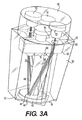
[0027]別の実施形態では、透過反射型測定は、図3に示されているファイバー無し透過反射型プローブ20を使用して遂行されている。透過反射型プローブ20は、レーザーダイオード12、14と少なくとも1つのLED16と試料検出器18を、測定部位22とインターフェースする。透過反射型プローブ20は、磨かれた外面45を有する円筒状光学ロッド40を備えている。1つの実施形態では、光学ロッド40は、溶融石英で作られており、外面45は表面の反射率を増すためにアルミニウムで被覆されている。別の実施形態では、光学ロッド40は、外面45へのアルミニウム被覆を有するガラスロッドである。光学ロッド40は、丸い検出窓46に垂直に配置されている。光学ロッド40の遠位端42は、光学ロッドの最遠位端が検出窓の遠位面49と軸方向に整列するようにして検出窓46の円形穴44へ挿し込まれていて、測定部位22の表面と直接接触している。入射光と後方散乱光の間の干渉を制限するために、光学ロッド40は、検出窓46に挿し込まれている遠位端42を含むその長さ全体に亘ってアルミニウムで被覆されている。加えて、光学ロッド40と検出窓46は、確実に測定部位22から後方散乱した放射線の実質部分が光学ロッド40に進入するようにするために密接に連結されている。
[0027] In another embodiment, transflective measurements are performed using the
[0028]電磁放射線ビームは、測定中に検出窓46を通して測定部位22へ透過される。而して、検出窓46は、試料マトリクスと検査器ハードウェアの間のインターフェースの役目を果たす。検出窓46は、先に説明されている圧迫/圧迫解除処置中に測定部位22へ機械的圧力を掛けるのにも使用されている。本開示に準拠する1つの実施形態では、検出窓46はガラス又は石英で構成されている。別の実施形態では、検出窓46は、λ0、λ1、及びλ2から成る波長範囲に高い透過率を有し、低い吸湿性を有し、且つ射出成形に適している熱可塑性ポリマーで構成されている。その様な熱可塑性ポリマーの例には、限定するわけではないが、環状ポリオレフィン(COP)、ポリメチルメタクリレート(PMMA)、及びポリスチレン(PS)が挙げられる。 [0028] The electromagnetic radiation beam is transmitted through the detection window 46 to the measurement site 22 during measurement. Thus, the detection window 46 serves as an interface between the sample matrix and the tester hardware. The detection window 46 is also used to apply mechanical pressure to the measurement site 22 during the compression / decompression procedure described above. In one embodiment consistent with the present disclosure, the detection window 46 is made of glass or quartz. In another embodiment, the detection window 46 is a thermoplastic polymer that has high transmission in the wavelength range consisting of λ 0 , λ 1 , and λ 2 , has low hygroscopicity, and is suitable for injection molding. It is configured. Examples of such thermoplastic polymers include, but are not limited to, cyclic polyolefin (COP), polymethyl methacrylate (PMMA), and polystyrene (PS).
[0029]光学ロッド40は、更に、内反射面を有するテーパの付いた管状ハウジング50に取り囲まれている。1つの実施形態では、内面52は、表面の反射率を増すためにアルミニウム被覆されている。テーパの付いた管状ハウジング50の遠位端54は、図3Bに示されている様に検出窓46と連結されている。本開示に準拠する1つの実施形態では、テーパの付いた管状ハウジング50は石英又はガラスで作られている。別の実施形態では、テーパの付いた管状ハウジング50は熱可塑性ポリマーで射出成形を使用して作られており、内面52は表面の反射率を増すためにアルミニウムで被覆されている。更に別の実施形態では、検出窓46及びテーパの付いた管状ハウジング50は、同じ熱可塑性ポリマーを使用して一体に射出成形されている。
[0029] The optical rod 40 is further surrounded by a tapered tubular housing 50 having an internal reflective surface. In one embodiment, the inner surface 52 is aluminized to increase surface reflectivity. The
[0030]テーパの付いた管状ハウジング50は、更に、レーザーダイオード及びLEDによって発せられる放射線ビームの形状付けをやり易くする。内面52の形状及び管状ハウジングのテーパ角度が、発せられたビームの測定部位22上への分散を誘導する。本開示に準拠する1つの好適な実施形態では、管状ハウジング50は、7.5°の円錐角度(長手方向の角度と壁の間の角度)を有する切頭円錐殻として構成されている。別の実施形態では、テーパの付いた管状ハウジング50の内面は、入射光を一様に測定部位22上へ分散させるためにファセット加工されている。管状ハウジングのファセット面の数は光学式プローブ20で使用されるレーザーダイオード及びLEDの数に対応している。1つの実施形態では、光学式プローブ20は、4つのレーザーダイオード(波長λ0とλ1それぞれに2つずつ)とλ2で作動する2つのLEDを含んでいる。その様な実施形態では、テーパの付いた管状ハウジング50の内面52は、図3A及び図3Bに示されている様に、ファセット加工の六角形状を有している。内面52のファセット面は凸状円筒の形をしており、各ファセット面の曲率半径は、対応する光源が異なった源からの測定部位22上への光の均一分散を提供するように、最適化されている。本開示の或る例示としての実施形態では、ファイバー無し透過反射型プローブ20は、血液中の糖の濃度を測定するための光学検出システムに使用されている。その様な実施形態では、λ0は1620nmとなるように選択され、λ1は約1380nmとなるように選択されており、λ0及びλ1で作動するレーザーと関連付けられる円筒状ファセット面の曲率半径はそれぞれ7.2mm及び6.1mmである。加えて、レーザーダイオード12、14の管状ハウジングの中心長手方向軸からの距離が発せられたビームの測定部位22上の分散を誘導する。以上に論じられている様に血液中の糖の濃度を測定するための或る実施形態では、レーザーダイオードの中心軸からの距離は5.3mmである。
[0030] The tapered tubular housing 50 further facilitates shaping of the radiation beam emitted by the laser diode and LED. The shape of the inner surface 52 and the taper angle of the tubular housing guide the dispersion of the emitted beam onto the measurement site 22. In one preferred embodiment consistent with the present disclosure, the tubular housing 50 is configured as a truncated conical shell having a 7.5 ° cone angle (the angle between the longitudinal angle and the wall). In another embodiment, the inner surface of the tapered tubular housing 50 is faceted to uniformly distribute incident light onto the measurement site 22. The number of facets on the tubular housing corresponds to the number of laser diodes and LEDs used in the
[0031]レーザーダイオード12、14は、温度安定性を期して、テーパの付いた管状ハウジング50の近位端56のヒートシンク60へ取り付けられている。1つの実施形態では、LED16は、更に、レーザーダイオードに隣接してヒートシンクへ取り付けられている。別の実施形態では、LEDは、レーザーダイオードのための安定した作動条件を維持するために、図3Aに示されている様にヒートシンク60下方の位置決め板62へ取り付けられている。
[0031] The
[0032]波長λ0、λ1、及びλ2を備える放射線ビームは、光学ロッド40の外面45とテーパの付いた管状ハウジング50の内面52で反射することによって測定部位22へ透過される。図4は、測定部位22上の4つのレーザーダイオードからの光の分散を示している。図に示されている様に、多数の源からの光は角度に関して均一に測定部位上へ分散されていて、光学ロッド40の周囲の区域は管状ハウジング50の縁周りの区域よりも多くの放射線を受けている。測定部位22へ入射する光のうちの幾らかは試料によって後方散乱し、後方散乱した光の極僅かが光学ロッド40の内部に到達し、光学ロッドの内面で反射することによって信号検出器18へ導かれる。試料検出器18(図3Aには示されていない)は、光学ロッド40の近位端44に配置されている。後方散乱光が検出器18に到達すると、試料マトリクス内の流体による波長λ0とλ1の差分吸収に比例する交番信号が生成される。次いで、流体中の標的分析物の濃度が、出力信号から、信号処理アルゴリズムを使用して計算される。 [0032] The radiation beam with wavelengths λ 0 , λ 1 , and λ 2 is transmitted to the measurement site 22 by reflection at the outer surface 45 of the optical rod 40 and the inner surface 52 of the tapered tubular housing 50. FIG. 4 shows the dispersion of light from the four laser diodes on the measurement site 22. As shown, the light from multiple sources is uniformly distributed over the measurement site with respect to angle, so that the area around the optical rod 40 is more radiation than the area around the edge of the tubular housing 50. Is receiving. Some of the light incident on the measurement site 22 is backscattered by the sample, and a very small amount of the backscattered light reaches the inside of the optical rod 40 and is reflected by the inner surface of the optical rod to the signal detector 18. Led. A sample detector 18 (not shown in FIG. 3A) is located at the proximal end 44 of the optical rod 40. When the backscattered light reaches the detector 18, an alternating signal is generated that is proportional to the differential absorption of the wavelengths λ 0 and λ 1 by the fluid in the sample matrix. The concentration of the target analyte in the fluid is then calculated from the output signal using a signal processing algorithm.
[0033]本開示及びOptical Bridge(商標)技術に準拠する1つの例示としての実施形態では、分析物検査器10は手持ち式ユニットである。再度図1を参照して、手持ち式ユニットは、測定結果のグラフィック表示のための画面27と、検査器を動作させるため及び標的分析物濃度を計算するためのプロセッサ23から成る搭載電子部品と、レーザーダイオード12、14及びLED16を駆動するための制御部モジュール24と、を備えている。手持ち式ユニットは、外部電源又は再充電式バッテリからパワー供給されていてもよいし、或いはUSBポートを通じてパワー供給されていてもよい。加えて、手持ち式分析物検査器10は、測定結果を記憶するメモリ25から成っている。メモリ25は、更に、画面27に表示されることになる検査器を使用するため及び検査器を動作させるための対話式命令を格納している。命令は、画面に表示される検査器を動作させるための音声/映像命令又は代わりに単純なテキスを提供するマルチメディアレコーディングを含む対話式の機能豊富な提示を備え、検査器を動作させるための及び使用するための命令を段階的に示すようになっていてもよい。検査器と一体に対話式命令を含んでいることにより、使用のための広範な訓練の必要性が省け、患者自身による検査及び医学専門家以外の人物による使用が可能になる。或る例示としての実施形態では、メモリ25は、更に、検査器の統計学的較正のための参照データベースを格納していてもよい。別の実施形態では、参照データベースは、遠隔の記憶装置から無線式又は有線式の接続を介してアクセスされるようになっていてもよい。同様に、被験者から分析物検査器10によって収集されたデータは、今後の参照のためにデータベースに記録されるようになっていてもよい。
[0033] In one exemplary embodiment consistent with the present disclosure and Optical Bridge ™ technology, the analyte tester 10 is a handheld unit. Referring again to FIG. 1, the hand-held unit includes a
[0034]分析物検査器10は、独立型システムとすることもできるし、又はデータの表示又は記憶を円滑化するために、また検査器が病気の状態と関連付けられる診断パラメータの継続監視のために使用されるのであれば治療行為が必要になったときに保健医療職員に信号を送るために、移動体機器又は静止型機器と連携して動作するものとすることもできる。移動体機器には、限定するわけではないが、分析物検査器10から離れていて分析物検査器10と通信している手持ち式機器又は無線式機器が含まれる。静止型機器には、限定するわけではないが、デスクトップコンピュータ、プリンタ、及び検査の結果を表示又は記憶する他の周辺機器が含まれる。或る例示としての実施形態では、分析物検査器10は、セッションの概要及び検査結果を含んでいる各患者ファイルを、コンパクトフラッシュ(登録商標)(CF)カードの様なリムーバブルメモリカード21上に記憶する。するとユーザーは、メモリカード21を使用して、患者情報及び処置データをコンピュータへ転送したりデータ及びセッション概要のプリントアウトを現出させたりすることができる。別の実施形態では、プロセッサ23からの結果は、データの表示又は記憶を円滑化するべく外部の移動体機器又は静止型機器へ直接転送される。例えば、プロセッサ23からの結果は、USBポート、IRDAポート、BLUETOOTH(登録商標)、又は他の無線リンクの様な、PCインターフェースを使用してPC29上に表示又は記憶されるようになっていてもよい。更に別の実施形態では、結果は無線式に又はケーブルを介してプリンタ31へ送信され、プリンタが結果を印刷して付き添う医療職員に使用させるようにすることができる。また、分析物検査器10は、より複雑なデータ処理又は分析を円滑化する別の移動体機器又は静止型機器へデータを送信することもできる。例えば、PC29と連携して動作する検査器がコンピュータによって更に処理させるためにデータを送る、ということもあろう。
[0034] The analyte tester 10 can be a stand-alone system or to facilitate the display or storage of data and for the continuous monitoring of diagnostic parameters with which the tester is associated with a disease state. It can also be used in conjunction with a mobile or stationary device to send signals to health care personnel when treatment is required. Mobile devices include, but are not limited to, handheld devices or wireless devices that are remote from the analyte tester 10 and are in communication with the analyte tester 10. Stationary devices include, but are not limited to, desktop computers, printers, and other peripheral devices that display or store test results. In one exemplary embodiment, the analyte tester 10 stores each patient file containing a session summary and test results on a
[0035]Optical Bridge(商標)法及び分析物検査器10はここでは血液中の糖の濃度を測定することに焦点を向けて説明されているが、本開示に提示されている方法及び装置は、血液又は他の流体中の他の分析物、例えば、尿、コレステロール、ニコチン、薬物類、など、の濃度を検出するのにも採用することができる。加えて、ファイバー無し透過反射型プローブ20及びその使用の方法は、赤外線波長範囲、可視線波長範囲、又は紫外線波長範囲で作動する何れの光学的検出システムに利用されてもよい。
[0035] Although the Optical Bridge ™ method and analyte tester 10 have been described herein with a focus on measuring the concentration of sugar in blood, the methods and apparatus presented in this disclosure are It can also be employed to detect the concentration of other analytes in blood or other fluids, such as urine, cholesterol, nicotine, drugs, and the like. In addition, the
[0036]ここに開示されている本発明の明細事項及び実践の考察から本発明の他の実施形態が当業者には自明であろう。明細事項及び諸例は単に例示として考えられるべきであり、本発明の真の範囲及び精神は次に続く特許請求の範囲によって指し示されるものとする。 [0036] Other embodiments of the invention will be apparent to those skilled in the art from consideration of the specification and practice of the invention disclosed herein. The specification and examples are to be considered merely as illustrative and the true scope and spirit of the invention is intended to be indicated by the following claims.
10 分析物検査器
12、14 レーザーダイオード
16 LED
18 試料検出器、信号検出器
20 光学式透過反射型プローブ
21 リムーバブルメモリカード
22 測定部位
23 プロセッサ
24 レーザーコントローラモジュール
25 メモリ
26 線形アクチュエータ
27 画面
28 Optical Bridge信号
29 PC
30 検出器出力電圧
31 プリンタ
34 副放射線源
40 光学ロッド
42 光学ロッドの遠位端
44 検出窓の円形穴
45 光学ロッドの磨かれた外面
46 検出窓
49 検出窓の遠位面
50 テーパの付いた管状ハウジング
52 ハウジング内面
54 ハウジング遠位端
56 ハウジング近位端
60 ヒートシンク
62 位置決め板
10
18 Sample detector,
30
Claims (22)
異なった波長を有している少なくとも2つの反復する放射期間を含む組み合わされた電磁放射線ビームを生成するための源であって、前記波長の少なくとも2つは前記標的分析物について異なった吸収係数を有している、組み合わされた電磁放射線ビームを生成するための源と、
前記標的領域によって後方散乱した前記放射線の一部を検出するように配列されている検出器であって、前記2つの反復する放射期間の各期間における前記組み合わされたビームの検出強度に比例する出力信号を生成する検出器と、
前記電磁放射線ビームを前記標的領域へ方向付けるとともに前記後方散乱放射線を前記検出器へ導くためのファイバー無し透過反射型プローブと、を備えており、
前記ファイバー無し透過反射型プローブは、内反射面を有して前記標的領域に近いほど小さくなるようにテーパの付いた管状ハウジングと、外反射面を有する円筒状光学ロッドと、前記電磁放射線ビームを前記標的領域へ透過させる検出窓と、を備えており、
前記管状ハウジングは、前記源の数に応じたファセット面を内面に有し、当該ファセット面は前記円筒状光学ロッドの周りに配置されており、
前記検出窓の前記標的領域に近い面である遠位面と、前記光学ロッドの前記標的領域に近い端部である遠位端とが整列されている、装置。 In a device for non-invasively examining a target area to measure the amount of a target analyte,
A source for generating a combined electromagnetic radiation beam comprising at least two repeated radiation periods having different wavelengths, wherein at least two of the wavelengths have different absorption coefficients for the target analyte. A source for generating a combined electromagnetic radiation beam;
A detector arranged to detect a portion of the radiation backscattered by the target region, the output being proportional to the detected intensity of the combined beam in each of the two repeated radiation periods A detector for generating a signal;
A fiberless transmission and reflection probe for directing the electromagnetic radiation beam to the target area and directing the backscattered radiation to the detector;
The non-fiber transmission / reflection probe includes an inner reflection surface and a tapered tubular housing tapered so as to be closer to the target area, a cylindrical optical rod having an outer reflection surface, and the electromagnetic radiation beam. A detection window that transmits to the target area,
The tubular housing has facets on the inner surface corresponding to the number of the sources, and the facets are arranged around the cylindrical optical rod;
The apparatus wherein the distal surface of the detection window that is near the target area and the distal end that is the end of the optical rod near the target area are aligned .
内反射面を有して前記標的領域に近いほど小さくなるようにテーパの付いた管状ハウジングと、検出窓と、前記検出窓に垂直に配置されている外反射面を有する光学ロッドと、を備えるファイバー無し透過反射型プローブを提供する段階と、
少なくとも2つの時分割成分から成る放射線ビームを生成するための2つの異なった波長で作動する少なくとも2つの光源を提供する段階と、
前記放射線ビームを、前記管状ハウジングの前記内面及び前記光学ロッドの前記外面で反射させることによって、前記検出窓を通じて標的領域へ透過させる段階と、
前記標的領域からの後方散乱ビームを、前記光学ロッドの内面で反射させることによって、前記検出器へ導く段階と、
前記後方散乱ビームを検出し前記標的領域による前記2つの波長の差分吸収を指し示す出力信号を発生させる検出器を提供する段階と、を備えており、
前記管状ハウジングは、前記源の数に応じたファセット面を内面に有し、当該ファセット面は前記光学ロッドの周りに配置されており、
前記検出窓の前記標的領域に近い面である遠位面と、前記光学ロッドの前記標的領域に近い端部である遠位端とが整列されている、方法。 In a non-invasive method of examining a target area to measure the amount of a target analyte,
A tubular housing having an inner reflection surface and tapered so as to be closer to the target area; a detection window; and an optical rod having an outer reflection surface arranged perpendicular to the detection window. Providing a fiberless transflective probe; and
Providing at least two light sources operating at two different wavelengths to produce a radiation beam composed of at least two time-division components;
Transmitting the radiation beam through the detection window to a target area by reflecting the radiation beam on the inner surface of the tubular housing and the outer surface of the optical rod;
Directing a backscattered beam from the target area to the detector by reflecting it on the inner surface of the optical rod;
Providing a detector for detecting the backscattered beam and generating an output signal indicative of differential absorption of the two wavelengths by the target region; and
The tubular housing has a facet surface on the inner surface corresponding to the number of the sources, and the facet surface is arranged around the optical rod;
The method includes aligning a distal surface that is a surface near the target region of the detection window and a distal end that is an end of the optical rod near the target region .
Applications Claiming Priority (3)
| Application Number | Priority Date | Filing Date | Title |
|---|---|---|---|
| US13/441,467 | 2012-04-06 | ||
| US13/441,467 US20130267799A1 (en) | 2012-04-06 | 2012-04-06 | Noninvasive measurement of analyte concentration using a fiberless transflectance probe |
| PCT/US2013/035250 WO2013152177A1 (en) | 2012-04-06 | 2013-04-04 | Noninvasive measurement of analyte concentration using a fiberless transflectance probe |
Publications (2)
| Publication Number | Publication Date |
|---|---|
| JP2015512326A JP2015512326A (en) | 2015-04-27 |
| JP6444857B2 true JP6444857B2 (en) | 2018-12-26 |
Family
ID=48227538
Family Applications (1)
| Application Number | Title | Priority Date | Filing Date |
|---|---|---|---|
| JP2015504720A Expired - Fee Related JP6444857B2 (en) | 2012-04-06 | 2013-04-04 | Non-invasive measurement of analyte concentration using a fiberless transmission and reflection probe |
Country Status (11)
| Country | Link |
|---|---|
| US (1) | US20130267799A1 (en) |
| EP (1) | EP2834620A1 (en) |
| JP (1) | JP6444857B2 (en) |
| KR (1) | KR20150050523A (en) |
| CN (1) | CN104395732A (en) |
| AU (1) | AU2013243441A1 (en) |
| CA (1) | CA2869607A1 (en) |
| HK (1) | HK1201325A1 (en) |
| IL (1) | IL234976A0 (en) |
| IN (1) | IN2014MN02147A (en) |
| WO (1) | WO2013152177A1 (en) |
Families Citing this family (5)
| Publication number | Priority date | Publication date | Assignee | Title |
|---|---|---|---|---|
| CN105249974A (en) * | 2015-10-15 | 2016-01-20 | 华南师范大学 | Pressure-modulation-spectrum-technology-based noninvasive glucose detection system and method |
| GB201812766D0 (en) * | 2018-08-06 | 2018-09-19 | Res & Innovation Uk | Optical multi-pass cells |
| US12029584B2 (en) * | 2019-10-01 | 2024-07-09 | Avid Najdahmadi | Light-based medical device |
| WO2021233561A1 (en) * | 2020-05-20 | 2021-11-25 | Diamontech Ag | Method and apparatus for analyzing a material with asymmetric or harmonic intensity modulation of excitation radiation |
| WO2021233560A1 (en) * | 2020-05-20 | 2021-11-25 | Diamontech Ag | Method and apparatus for analyte measurement including real-time quality assessment and improvement |
Family Cites Families (18)
| Publication number | Priority date | Publication date | Assignee | Title |
|---|---|---|---|---|
| US3986777A (en) * | 1974-08-22 | 1976-10-19 | Weber Dental Mfg. Co., Div. Of Sterndent Corporation | Tristimulus colorimeter for use in the fabrication of artificial teeth |
| US5178142A (en) | 1989-05-23 | 1993-01-12 | Vivascan Corporation | Electromagnetic method and apparatus to measure constituents of human or animal tissue |
| EP0401453B1 (en) | 1989-05-23 | 1992-09-02 | Biosensors Technology, Inc. | Method for determining by absorption of radiations the concentration of substances in absorbing and turbid matrices |
| US5112124A (en) | 1990-04-19 | 1992-05-12 | Worcester Polytechnic Institute | Method and apparatus for measuring the concentration of absorbing substances |
| US5183042A (en) | 1989-05-23 | 1993-02-02 | Vivascan Corporation | Electromagnetic method and apparatus to measure constituents of human or animal tissue |
| US5137023A (en) | 1990-04-19 | 1992-08-11 | Worcester Polytechnic Institute | Method and apparatus for monitoring blood analytes noninvasively by pulsatile photoplethysmography |
| DE69221878T2 (en) * | 1991-07-03 | 1998-03-26 | Vivascan Corp., Southboro, Ma. | METHOD AND DEVICE FOR ELECTROMAGNETICALLY DETERMINING SUBSTANCES PRESENT IN LIVING TISSUE |
| US5277181A (en) | 1991-12-12 | 1994-01-11 | Vivascan Corporation | Noninvasive measurement of hematocrit and hemoglobin content by differential optical analysis |
| WO1993012712A1 (en) | 1991-12-31 | 1993-07-08 | Vivascan Corporation | Blood constituent determination based on differential spectral analysis |
| US5851178A (en) * | 1995-06-02 | 1998-12-22 | Ohmeda Inc. | Instrumented laser diode probe connector |
| US6174424B1 (en) * | 1995-11-20 | 2001-01-16 | Cirrex Corp. | Couplers for optical fibers |
| US5830137A (en) * | 1996-11-18 | 1998-11-03 | University Of South Florida | Green light pulse oximeter |
| US6070093A (en) * | 1997-12-02 | 2000-05-30 | Abbott Laboratories | Multiplex sensor and method of use |
| US7003337B2 (en) * | 2002-04-26 | 2006-02-21 | Vivascan Corporation | Non-invasive substance concentration measurement using and optical bridge |
| US8175666B2 (en) * | 2002-04-26 | 2012-05-08 | Grove Instruments, Inc. | Three diode optical bridge system |
| JP2004081427A (en) * | 2002-08-26 | 2004-03-18 | Kenji Yoshikawa | Apparatus for measuring water content in living body |
| JP2004290545A (en) * | 2003-03-28 | 2004-10-21 | Citizen Watch Co Ltd | Blood analyzer |
| US8523785B2 (en) * | 2005-09-06 | 2013-09-03 | Covidien Lp | Method and apparatus for measuring analytes |
-
2012
- 2012-04-06 US US13/441,467 patent/US20130267799A1/en not_active Abandoned
-
2013
- 2013-04-04 CA CA2869607A patent/CA2869607A1/en not_active Abandoned
- 2013-04-04 WO PCT/US2013/035250 patent/WO2013152177A1/en active Application Filing
- 2013-04-04 CN CN201380023695.9A patent/CN104395732A/en active Pending
- 2013-04-04 IN IN2147MUN2014 patent/IN2014MN02147A/en unknown
- 2013-04-04 EP EP13719647.3A patent/EP2834620A1/en not_active Withdrawn
- 2013-04-04 KR KR1020147031005A patent/KR20150050523A/en not_active Application Discontinuation
- 2013-04-04 AU AU2013243441A patent/AU2013243441A1/en not_active Abandoned
- 2013-04-04 JP JP2015504720A patent/JP6444857B2/en not_active Expired - Fee Related
-
2014
- 2014-10-02 IL IL234976A patent/IL234976A0/en unknown
-
2015
- 2015-02-16 HK HK15101708.4A patent/HK1201325A1/en unknown
Also Published As
| Publication number | Publication date |
|---|---|
| KR20150050523A (en) | 2015-05-08 |
| CA2869607A1 (en) | 2013-10-10 |
| WO2013152177A1 (en) | 2013-10-10 |
| JP2015512326A (en) | 2015-04-27 |
| CN104395732A (en) | 2015-03-04 |
| US20130267799A1 (en) | 2013-10-10 |
| HK1201325A1 (en) | 2015-08-28 |
| EP2834620A1 (en) | 2015-02-11 |
| WO2013152177A8 (en) | 2013-12-05 |
| IN2014MN02147A (en) | 2015-08-21 |
| AU2013243441A1 (en) | 2014-10-30 |
| IL234976A0 (en) | 2014-12-31 |
Similar Documents
| Publication | Publication Date | Title |
|---|---|---|
| US6630673B2 (en) | Non-invasive sensor capable of determining optical parameters in a sample having multiple layers | |
| US10188325B2 (en) | Wearable, noninvasive glucose sensing methods and systems | |
| US6403944B1 (en) | System for measuring a biological parameter by means of photoacoustic interaction | |
| US9915608B2 (en) | Optical sensor for determining the concentration of an analyte | |
| US6804002B2 (en) | Method and device for measuring concentration of glucose or other substances in blood | |
| JP4393705B2 (en) | Noninvasive optical sensor with control of tissue temperature | |
| US8352005B2 (en) | Noninvasive blood analysis by optical probing of the veins under the tongue | |
| US20210052164A1 (en) | Sensor for tissue measurements | |
| JP6444857B2 (en) | Non-invasive measurement of analyte concentration using a fiberless transmission and reflection probe | |
| US9173603B2 (en) | Non-invasive device and method for measuring bilirubin levels | |
| CN107427219A (en) | Optoacoustic sensing device further and its operating method | |
| JP3994588B2 (en) | Noninvasive blood glucose meter | |
| JP2007083028A (en) | Noninvasive inspecting apparatus | |
| GB2322941A (en) | In-vivo photoacoustic measurement | |
| JP4772408B2 (en) | Optical biological information measurement system and coupling layer used for optical information measurement | |
| US20080033263A1 (en) | Method and system for determining the contribution of hemoglobin and myoglobin to in vivo optical spectra | |
| US20130267798A1 (en) | Noninvasive measurement of analyte concentration using a fiberless transflectance probe | |
| KR100883153B1 (en) | Instrument for noninvasively measuring blood sugar level | |
| CN209899401U (en) | Four-wavelength combined noninvasive glucometer | |
| Talukdar | Non-Invasive Measurement of Glucose Content in Human Body: A Comparative Study |
Legal Events
| Date | Code | Title | Description |
|---|---|---|---|
| A621 | Written request for application examination |
Free format text: JAPANESE INTERMEDIATE CODE: A621 Effective date: 20160323 |
|
| A131 | Notification of reasons for refusal |
Free format text: JAPANESE INTERMEDIATE CODE: A131 Effective date: 20170127 |
|
| A977 | Report on retrieval |
Free format text: JAPANESE INTERMEDIATE CODE: A971007 Effective date: 20170125 |
|
| A601 | Written request for extension of time |
Free format text: JAPANESE INTERMEDIATE CODE: A601 Effective date: 20170426 |
|
| A521 | Request for written amendment filed |
Free format text: JAPANESE INTERMEDIATE CODE: A523 Effective date: 20170727 |
|
| A131 | Notification of reasons for refusal |
Free format text: JAPANESE INTERMEDIATE CODE: A131 Effective date: 20171212 |
|
| A601 | Written request for extension of time |
Free format text: JAPANESE INTERMEDIATE CODE: A601 Effective date: 20180312 |
|
| A521 | Request for written amendment filed |
Free format text: JAPANESE INTERMEDIATE CODE: A523 Effective date: 20180510 |
|
| TRDD | Decision of grant or rejection written | ||
| A01 | Written decision to grant a patent or to grant a registration (utility model) |
Free format text: JAPANESE INTERMEDIATE CODE: A01 Effective date: 20181030 |
|
| A61 | First payment of annual fees (during grant procedure) |
Free format text: JAPANESE INTERMEDIATE CODE: A61 Effective date: 20181128 |
|
| R150 | Certificate of patent or registration of utility model |
Ref document number: 6444857 Country of ref document: JP Free format text: JAPANESE INTERMEDIATE CODE: R150 |
|
| R250 | Receipt of annual fees |
Free format text: JAPANESE INTERMEDIATE CODE: R250 |
|
| LAPS | Cancellation because of no payment of annual fees |