JP6443714B2 - Steam generating apparatus, adsorbent container, and steam generating method - Google Patents
Steam generating apparatus, adsorbent container, and steam generating method Download PDFInfo
- Publication number
- JP6443714B2 JP6443714B2 JP2014074334A JP2014074334A JP6443714B2 JP 6443714 B2 JP6443714 B2 JP 6443714B2 JP 2014074334 A JP2014074334 A JP 2014074334A JP 2014074334 A JP2014074334 A JP 2014074334A JP 6443714 B2 JP6443714 B2 JP 6443714B2
- Authority
- JP
- Japan
- Prior art keywords
- adsorbent
- zeolite
- steam
- steam generator
- hot water
- Prior art date
- Legal status (The legal status is an assumption and is not a legal conclusion. Google has not performed a legal analysis and makes no representation as to the accuracy of the status listed.)
- Active
Links
- 238000000034 method Methods 0.000 title claims description 106
- 239000003463 adsorbent Substances 0.000 title claims description 37
- XLYOFNOQVPJJNP-UHFFFAOYSA-N water Substances O XLYOFNOQVPJJNP-UHFFFAOYSA-N 0.000 claims description 222
- 239000000945 filler Substances 0.000 claims description 28
- 238000003860 storage Methods 0.000 claims description 13
- 238000007599 discharging Methods 0.000 claims description 10
- 238000001035 drying Methods 0.000 claims 1
- HNPSIPDUKPIQMN-UHFFFAOYSA-N dioxosilane;oxo(oxoalumanyloxy)alumane Chemical compound O=[Si]=O.O=[Al]O[Al]=O HNPSIPDUKPIQMN-UHFFFAOYSA-N 0.000 description 226
- 229910021536 Zeolite Inorganic materials 0.000 description 225
- 239000010457 zeolite Substances 0.000 description 225
- 230000008929 regeneration Effects 0.000 description 93
- 238000011069 regeneration method Methods 0.000 description 93
- 230000008569 process Effects 0.000 description 88
- 238000001179 sorption measurement Methods 0.000 description 63
- 230000008859 change Effects 0.000 description 23
- 238000010438 heat treatment Methods 0.000 description 17
- 230000001172 regenerating effect Effects 0.000 description 16
- 239000002351 wastewater Substances 0.000 description 14
- 238000004519 manufacturing process Methods 0.000 description 13
- 230000006837 decompression Effects 0.000 description 12
- 238000005516 engineering process Methods 0.000 description 12
- 238000012545 processing Methods 0.000 description 12
- 238000009434 installation Methods 0.000 description 11
- PNEYBMLMFCGWSK-UHFFFAOYSA-N aluminium oxide Inorganic materials [O-2].[O-2].[O-2].[Al+3].[Al+3] PNEYBMLMFCGWSK-UHFFFAOYSA-N 0.000 description 10
- 229910000831 Steel Inorganic materials 0.000 description 9
- 239000011324 bead Substances 0.000 description 9
- 238000001816 cooling Methods 0.000 description 9
- 239000011521 glass Substances 0.000 description 9
- 239000010959 steel Substances 0.000 description 9
- 239000002918 waste heat Substances 0.000 description 9
- 238000010792 warming Methods 0.000 description 8
- 230000006399 behavior Effects 0.000 description 7
- 238000012856 packing Methods 0.000 description 7
- 238000000926 separation method Methods 0.000 description 7
- 230000000052 comparative effect Effects 0.000 description 6
- 230000007423 decrease Effects 0.000 description 6
- 238000003795 desorption Methods 0.000 description 6
- 238000005265 energy consumption Methods 0.000 description 6
- 238000005304 joining Methods 0.000 description 6
- 238000010926 purge Methods 0.000 description 6
- 239000002699 waste material Substances 0.000 description 6
- 238000007872 degassing Methods 0.000 description 5
- 230000006866 deterioration Effects 0.000 description 4
- 238000002474 experimental method Methods 0.000 description 4
- 230000006870 function Effects 0.000 description 4
- 239000007789 gas Substances 0.000 description 4
- 229910052751 metal Inorganic materials 0.000 description 4
- 239000002184 metal Substances 0.000 description 4
- 230000009467 reduction Effects 0.000 description 4
- 230000000274 adsorptive effect Effects 0.000 description 3
- 150000001412 amines Chemical class 0.000 description 3
- 238000011161 development Methods 0.000 description 3
- 230000018109 developmental process Effects 0.000 description 3
- 239000002803 fossil fuel Substances 0.000 description 3
- 239000007788 liquid Substances 0.000 description 3
- 238000005259 measurement Methods 0.000 description 3
- CURLTUGMZLYLDI-UHFFFAOYSA-N Carbon dioxide Chemical compound O=C=O CURLTUGMZLYLDI-UHFFFAOYSA-N 0.000 description 2
- 229910001341 Crude steel Inorganic materials 0.000 description 2
- VYPSYNLAJGMNEJ-UHFFFAOYSA-N Silicium dioxide Chemical compound O=[Si]=O VYPSYNLAJGMNEJ-UHFFFAOYSA-N 0.000 description 2
- 238000006243 chemical reaction Methods 0.000 description 2
- 238000009826 distribution Methods 0.000 description 2
- 238000004134 energy conservation Methods 0.000 description 2
- 239000000741 silica gel Substances 0.000 description 2
- 229910002027 silica gel Inorganic materials 0.000 description 2
- 238000009628 steelmaking Methods 0.000 description 2
- 230000001954 sterilising effect Effects 0.000 description 2
- 238000004659 sterilization and disinfection Methods 0.000 description 2
- 239000000126 substance Substances 0.000 description 2
- 238000012360 testing method Methods 0.000 description 2
- GWEVSGVZZGPLCZ-UHFFFAOYSA-N Titan oxide Chemical compound O=[Ti]=O GWEVSGVZZGPLCZ-UHFFFAOYSA-N 0.000 description 1
- 238000007664 blowing Methods 0.000 description 1
- 229910002092 carbon dioxide Inorganic materials 0.000 description 1
- 239000001569 carbon dioxide Substances 0.000 description 1
- 238000009749 continuous casting Methods 0.000 description 1
- 239000000498 cooling water Substances 0.000 description 1
- 230000007797 corrosion Effects 0.000 description 1
- 238000005260 corrosion Methods 0.000 description 1
- 230000000694 effects Effects 0.000 description 1
- 230000005611 electricity Effects 0.000 description 1
- 238000001704 evaporation Methods 0.000 description 1
- 230000008020 evaporation Effects 0.000 description 1
- 239000000446 fuel Substances 0.000 description 1
- 230000007246 mechanism Effects 0.000 description 1
- 238000005457 optimization Methods 0.000 description 1
- 230000008520 organization Effects 0.000 description 1
- 229920000642 polymer Polymers 0.000 description 1
- 239000011148 porous material Substances 0.000 description 1
- 238000011160 research Methods 0.000 description 1
- 238000002791 soaking Methods 0.000 description 1
- 239000002594 sorbent Substances 0.000 description 1
- 230000001360 synchronised effect Effects 0.000 description 1
- OGIDPMRJRNCKJF-UHFFFAOYSA-N titanium oxide Inorganic materials [Ti]=O OGIDPMRJRNCKJF-UHFFFAOYSA-N 0.000 description 1
- 238000012546 transfer Methods 0.000 description 1
Images


Classifications
-
- Y—GENERAL TAGGING OF NEW TECHNOLOGICAL DEVELOPMENTS; GENERAL TAGGING OF CROSS-SECTIONAL TECHNOLOGIES SPANNING OVER SEVERAL SECTIONS OF THE IPC; TECHNICAL SUBJECTS COVERED BY FORMER USPC CROSS-REFERENCE ART COLLECTIONS [XRACs] AND DIGESTS
- Y02—TECHNOLOGIES OR APPLICATIONS FOR MITIGATION OR ADAPTATION AGAINST CLIMATE CHANGE
- Y02P—CLIMATE CHANGE MITIGATION TECHNOLOGIES IN THE PRODUCTION OR PROCESSING OF GOODS
- Y02P80/00—Climate change mitigation technologies for sector-wide applications
- Y02P80/10—Efficient use of energy, e.g. using compressed air or pressurized fluid as energy carrier
- Y02P80/15—On-site combined power, heat or cool generation or distribution, e.g. combined heat and power [CHP] supply
Landscapes
- Control Of Steam Boilers And Waste-Gas Boilers (AREA)
Description
本発明は、蒸気生成装置、及び蒸気生成方法に関する。 The present invention relates to a steam generation apparatus and a steam generation method.
化石燃料の資源的制約や地球温暖化問題などを背景として、省エネルギーの更なる要請はますます強まっている。例えば、特許文献1には、自然エネルギーを用いて、ゼオライトに対する水の吸着・脱着を可逆的に行うことによって過熱水蒸気を生成する、ゼオライト式の過熱水蒸気生成装置が開示されている。また、例えば、特許文献2には、ガスエンジン又は燃料電池を用いたコージェネレーションシステムとして、吸着器が吸着過程にあるときに上水を通水するとともに、吸着器が再生過程にあるときは当該吸着器に接続されている凝縮器に上水を通水するように構成された吸着ヒートポンプシステムが開示されている。また、特許文献2では、吸着器にシリカゲル及びゼオライト等の吸着材を充填することが開示されている。
With the background of fossil fuel resource constraints and global warming issues, further demands for energy conservation are increasing. For example, Patent Document 1 discloses a zeolitic superheated steam generating device that generates superheated steam by reversibly adsorbing and desorbing water with respect to zeolite using natural energy. Further, for example, in
例えば、鉄鋼産業や石油化学産業では、50〜100℃の排温水が大量に発生する。このような排温水は、再生エネルギーとして活用するには温度が低いため、回収されずに廃棄されていた。一方、このような排温水は、廃棄するには温度が高いため、冷却塔などを利用して、放熱し、廃棄していた。換言すると、廃棄するために、別途エネルギーを用いなければならなかった。そこで、本発明者らは、このような従来廃棄されていた排温水を回収して、再生エネルギーを生成すべく、ゼオライトを用いた蒸気生成装置に着目した。また、この蒸気生成装置を用いたシステムでは、排温水を回収して、再生エネルギーを生成する上では、継続的に再生エネルギー(水蒸気)を生成できることが求められる。つまり、ゼオライトを用いた蒸気生成装置を用いる上では、ゼオライトへの水の吸着・脱着を可逆的に繰り返すことが可能であり、連続的に水蒸気を生成可能な技術が必要となる。 For example, in the steel industry and the petrochemical industry, a large amount of hot water of 50 to 100 ° C. is generated. Such waste water has been discarded without being recovered because it has a low temperature to be used as renewable energy. On the other hand, such waste hot water has a high temperature to be discarded, and therefore, heat is dissipated and discarded using a cooling tower or the like. In other words, additional energy had to be used for disposal. Therefore, the present inventors paid attention to a steam generation apparatus using zeolite in order to recover such waste water that has been conventionally discarded and generate regenerated energy. Moreover, in the system using this steam production | generation apparatus, when collect | recovering waste temperature water and producing | generating regeneration energy, it is calculated | required that regeneration energy (water vapor | steam) can be produced | generated continuously. In other words, when using a vapor generating apparatus using zeolite, it is possible to reversibly repeat the adsorption and desorption of water on the zeolite, and a technique capable of continuously generating water vapor is required.
本発明は、上記の問題に鑑み、50〜100℃の排温水から水蒸気を生成でき、かつ、冷却塔などを用いた排温水の廃棄よりも少ない消費エネルギーで連続的に水蒸気を生成できる技術を提供することを課題とする。 In view of the above problems, the present invention is a technology that can generate water vapor from waste water at 50 to 100 ° C., and can continuously generate water vapor with less energy consumption than waste water discharge using a cooling tower or the like. The issue is to provide.
本発明は、上述した課題を解決するため、50〜100℃の排温水をゼオライトに吸着させ、その際の吸着熱により水蒸気を生成することとした。また、本発明では、露点が−20℃以下の乾燥空気を供給してゼオライトなどの多孔質体の吸着水を脱着(再生)再生することとした。 In the present invention, in order to solve the above-described problem, 50 to 100 ° C. waste water is adsorbed on zeolite, and steam is generated by heat of adsorption at that time. Further, in the present invention, dry air having a dew point of −20 ° C. or less is supplied to desorb (regenerate) and regenerate the adsorbed water of a porous body such as zeolite.
詳細には、本発明は、内部にゼオライトが充填されたゼオライト収容部と、前記ゼオライト収容部に、50〜100℃の温水を供給する温水供給部と、前記ゼオライト収容部のゼオライトに前記温水を吸着させることで発生した蒸気を排出する蒸気排出部と、前記ゼオライト収容部に、露点が−20℃以下の乾燥空気を供給し、前記ゼオライトに吸着された吸着水を脱着して当該ゼオライトを再生させる乾燥空気供給部と、を備える蒸気生成装
置である。
Specifically, the present invention includes a zeolite housing portion filled with zeolite therein, a hot water supply portion that supplies hot water of 50 to 100 ° C. to the zeolite housing portion, and the hot water to the zeolite in the zeolite housing portion. Dry air with a dew point of −20 ° C. or less is supplied to the steam discharge part for discharging the steam generated by the adsorption and the zeolite housing part, and the adsorbed water adsorbed on the zeolite is desorbed to regenerate the zeolite. And a dry air supply unit.
本発明に係る蒸気生成装置は、ゼオライト収容部に充填されたゼオライトと温水供給部から供給される温水とが接して、その際に発生する吸着熱により水蒸気を生成する。温水には、例えば、鉄鋼産業や石油化学産業において、従来回収されずに廃棄されていた50〜100℃の排温水が例示される。本発明に係る蒸気生成装置では、従来廃棄されていた排温水から水蒸気を生成することができる。また、従来、排温水の廃棄には、冷却塔で冷却するなど、別途エネルギーを用いなければならなかった。しかしながら、本発明に係る蒸気生成装置によれば、そのような廃棄のための無駄なエネルギーを用いる必要もない。また、本発明に係る蒸気生成装置で生成された水蒸気は、生産プロセス等で利用でき、従来廃棄していた温熱を高品質なエネルギーに転嫁できる。更に、本発明に係る蒸気生成装置は、乾燥空気供給部を備えることで、ゼオライトに吸着されている吸着水を効果的に脱着させることができる。その結果、ゼオライトの再生が促進され、連続的に水蒸気を生成することができる。 In the steam generating apparatus according to the present invention, the zeolite filled in the zeolite housing part and the hot water supplied from the hot water supply part come into contact with each other, and steam is generated by the heat of adsorption generated at that time. Examples of the hot water include 50 to 100 ° C. waste water that has been discarded without being collected in the steel industry and petrochemical industry. In the steam generation apparatus according to the present invention, water vapor can be generated from waste hot water that has been conventionally discarded. In addition, conventionally, waste heat water must be disposed of separately, for example, by cooling with a cooling tower. However, according to the steam generator according to the present invention, it is not necessary to use such wasteful energy for disposal. Moreover, the water vapor | steam produced | generated with the vapor | steam production | generation apparatus which concerns on this invention can be utilized by a production process etc., and the heat which was discarded conventionally can be passed on to high quality energy. Furthermore, the steam generating apparatus according to the present invention includes a dry air supply unit, so that the adsorbed water adsorbed on the zeolite can be effectively desorbed. As a result, regeneration of the zeolite is promoted, and water vapor can be continuously generated.
なお、ゼオライトの吸着熱を利用した吸着式ヒートポンプの原理自体は、例えば、特許文献2(特開2006−29605)に記載されているように、従来より知られている。しかしながら、これらは一般に、ゼオライトが充填された蒸気生成器内に熱交換器が内蔵され、その熱交換器に水を供給することで加熱/冷却をして蒸気発生(脱着)/蒸気吸着をさせる間接熱交換方式であった。そのため、従来の吸着式ヒートポンプは、本発明に係る蒸気生成装置のような、ゼオライトと温水との吸着熱によって供給温水自身を加熱して蒸気を発生させる直接熱交換方式と比較すると、熱交換性能が悪く、また、熱交換性能を向上するとなるとよりシステムが複雑化するといった問題があった。これに対し、本発明に係る蒸気生成装置は、熱交換器が内蔵されておらず、従来よりも簡易な構成でありながら、廃棄された温水を利用して水蒸気を生成することができる。なお、ゼオライトに代えて他の多孔質体を用いてもよい。他の多孔質体には、シリカゲル、アルミナ、酸化チタン、高分子収着剤が例示される。 The principle of an adsorption heat pump that uses the adsorption heat of zeolite has been conventionally known, for example, as described in Patent Document 2 (Japanese Patent Laid-Open No. 2006-29605). However, in general, a heat exchanger is built in a steam generator filled with zeolite, and water is supplied to the heat exchanger to be heated / cooled to generate (desorb) / adsorb steam. It was an indirect heat exchange system. Therefore, the conventional adsorption heat pump has a heat exchange performance as compared with the direct heat exchange method in which the supply hot water itself is heated by the adsorption heat of the zeolite and the hot water to generate steam, such as the steam generation apparatus according to the present invention. However, there is a problem that the system becomes more complicated when the heat exchange performance is improved. On the other hand, the steam generator according to the present invention does not have a built-in heat exchanger and has a simpler configuration than the conventional one, but can generate steam using the discarded warm water. Note that another porous body may be used instead of zeolite. Examples of other porous materials include silica gel, alumina, titanium oxide, and polymer sorbent.
ここで、本発明に係る蒸気生成装置は、前記ゼオライト収容部、前記温水供給部、及び前記乾燥空気供給部を複数備え、前記複数のゼオライト収容部は、並列に配置され、前記温水供給部、及び前記乾燥空気供給部を制御する制御部を更に備え、前記制御部は、各ゼオライト収容部内におけるゼオライトの吸着及び脱着が連続して行われるよう、各温水供給部による温水の供給のタイミング、及び各乾燥空気供給部による乾燥空気の供給のタイミングを制御するようにしてもよい。 Here, the steam generation apparatus according to the present invention includes a plurality of the zeolite storage unit, the hot water supply unit, and the dry air supply unit, wherein the plurality of zeolite storage units are arranged in parallel, the hot water supply unit, And a control unit for controlling the dry air supply unit, the control unit, the timing of the supply of hot water by each hot water supply unit so that the adsorption and desorption of zeolite in each zeolite storage unit is continuously performed, and You may make it control the timing of supply of the dry air by each dry air supply part.
ゼオライト収容部等を複数備え、複数のゼオライト収容部は、並列に配置する構成とすることで、一のゼオライト収容部のゼオライトが脱着している場合でも、他のゼオライト収容部のゼオライトで吸着することができる。そのため、装置全体として、より連続的に水蒸気を生成することができる。 Provided with a plurality of zeolite accommodating parts, etc., and the plurality of zeolite accommodating parts are arranged in parallel, so that even if the zeolite of one zeolite accommodating part is desorbed, it is adsorbed by the zeolite of the other zeolite accommodating part be able to. Therefore, water vapor can be generated more continuously as the entire apparatus.
また、前記温水供給部は、前記ゼオライト収容部の下部に設けられ、前記蒸気排出部は、前記ゼオライト収容部の上部に設けられていてもよい。温水をゼオライトの下部から供給することで、水平方向の温水の分布を均一にすることができる。また、ゼオライトの水平方向の断面から一様に生成された水蒸気は、ゼオライトの上部から排出することができる。 Moreover, the said warm water supply part may be provided in the lower part of the said zeolite accommodating part, and the said steam discharge part may be provided in the upper part of the said zeolite accommodating part. By supplying the hot water from the lower part of the zeolite, the distribution of the hot water in the horizontal direction can be made uniform. Moreover, the water vapor | steam produced | generated uniformly from the horizontal cross section of a zeolite can be discharged | emitted from the upper part of a zeolite.
なお、前記温水供給部は、前記ゼオライト収容部の上部に設けてもよい。この場合、生成された水蒸気と供給される温水との熱交換を抑制するため、前記蒸気排出部は、前記ゼオライト収容部の下部に設けた方がよい。 The hot water supply unit may be provided on the upper part of the zeolite storage unit. In this case, in order to suppress heat exchange between the generated water vapor and the supplied hot water, it is preferable that the steam discharge part is provided at the lower part of the zeolite housing part.
また、前記ゼオライト収容部は、内部に複数のゼオライト層を有するものでもよい。ゼオライト層は、1層でもよいが、複数とすることでより効率よく水蒸気を生成することができる。例えば、下段のゼオライト層を予熱用、上段のゼオライト層を蒸気生成用といったように、ゼオライト層毎に機能を割り当ててもよい。このようにすることで、より効率よく水蒸気を生成することができる。 Moreover, the said zeolite accommodating part may have a some zeolite layer inside. Although the number of zeolite layers may be one, water vapor can be generated more efficiently by using a plurality of zeolite layers. For example, a function may be assigned to each zeolite layer such that the lower zeolite layer is used for preheating and the upper zeolite layer is used for steam generation. By doing in this way, water vapor | steam can be produced | generated more efficiently.
また、前記乾燥空気供給部は、前記ゼオライト収容部内における前記乾燥空気の速度が1.5m/sec以下となるように当該乾燥空気を供給するようにしてもよい。これにより、ゼオライトを再生する際、ゼオライト収容部内の存在する再生空気の偏流を抑制することができる。 The dry air supply unit may supply the dry air so that the speed of the dry air in the zeolite housing unit is 1.5 m / sec or less. Thereby, when reproducing | regenerating a zeolite, the drift of the reproduction | regeneration air which exists in a zeolite accommodating part can be suppressed.
また、本発明に係る蒸気生成装置は、前記温水供給部から供給される温水を加温する温水加温部を更に備える構成でもよい。これにより、水蒸気を生成する能力をより向上することができる。 Moreover, the structure which further comprises the warm water heating part which heats the warm water supplied from the said warm water supply part may be sufficient as the steam generation apparatus which concerns on this invention. Thereby, the ability to generate water vapor can be further improved.
また、本発明に係る蒸気生成装置は、前記乾燥空気調整部から供給される乾燥空気の温度を調整する乾燥空気の温度調整部と、前記乾燥空気調整部から供給される乾燥空気の湿度を調整する乾燥空気の湿度調整部と、のうち少なくとも何れか一方を更に備える構成でもよい。温度調整部を備えることで、例えば供給される乾燥空気の温度を上げることで、ゼオライトを再生する能力をより向上することができる。また、湿度調整部を備えることで、例えば供給される乾燥空気の湿度を下げることで、ゼオライト内の水分除去をより効率よく行うことができる。その結果、ゼオライトを再生する能力をより向上することができる。 The steam generator according to the present invention adjusts the temperature of the dry air supplied from the dry air adjusting unit and the humidity of the dry air supplied from the dry air adjusting unit. It may be configured to further include at least one of a humidity adjusting unit for dry air to be performed. By providing the temperature adjustment unit, for example, the ability to regenerate zeolite can be further improved by increasing the temperature of the supplied dry air. In addition, by providing the humidity adjusting unit, for example, by reducing the humidity of the supplied dry air, the moisture in the zeolite can be removed more efficiently. As a result, the ability to regenerate the zeolite can be further improved.
また、本発明に係る蒸気生成装置は、前記ゼオライトの再生後に、前記ゼオライト収容部内の空気を真空引きして脱気する脱気部を更に備える構成でもよい。これにより、生成された水蒸気内に空気が存在することを抑制することができる。 The steam generation apparatus according to the present invention may further include a deaeration unit that evacuates and degass the air in the zeolite storage unit after regeneration of the zeolite. Thereby, it can suppress that air exists in the produced | generated water vapor | steam.
また、本発明に係る蒸気生成装置は、前記蒸気排出部から排出する蒸気の一部を前記ゼオライト収容部に供給し、当該ゼオライト収容部内のゼオライトを予熱する予熱部を更に備える構成でもよい。これにより、ゼオライトの一部を予熱することが可能となり、その結果、水蒸気を生成する能力をより向上することができる。 Moreover, the structure which further comprises the preheating part which supplies a part of the vapor | steam discharged | emitted from the said steam discharge part to the said zeolite accommodating part, and preheats the zeolite in the said zeolite accommodating part may be sufficient as the steam production | generation apparatus which concerns on this invention. Thereby, it becomes possible to pre-heat a part of zeolite, As a result, the capability to produce | generate water vapor | steam can be improved more.
また、本発明に係る蒸気生成装置は、前記ゼオライト収容部内の温度情報、又は圧力情報に基づいて、前記温水供給部による温水の供給のタイミング、又は、前記乾燥空気供給部による乾燥空気の供給のタイミングを制御する制御部を更に備える構成でもよい。これにより、より効率よく水蒸気の生成やゼオライトの再生を行うことができる。 Further, the steam generating device according to the present invention is configured to supply hot water by the hot water supply unit or supply dry air by the dry air supply unit based on temperature information or pressure information in the zeolite storage unit. The structure which further has a control part which controls timing may be sufficient. Thereby, the production | generation of water vapor | steam and the reproduction | regeneration of a zeolite can be performed more efficiently.
ここで、ゼオライト収容部に充填されたゼオライトと温水供給部から供給される温水とが接して、その際に発生する吸着熱により水蒸気を生成する際、ゼオライト収容部は、急激に温度変化(例えば、温度上昇)することが想定される。また、例えば、ゼオライト収容部が急激に温度上昇し、ゼオライト収容部の温度が高くなりすぎると、ゼオライト収容部の吸着量が低下することが考えられる。また、ゼオライト収容部が急激に温度変化すると、ゼオライト収容部が破損してしまうことも考えられる。そこで、本発明は、このようなゼオライト収容部の温度変化を緩和するようにしてもよい。 Here, when the zeolite filled in the zeolite housing portion and the hot water supplied from the hot water supply portion come into contact with each other and generate water vapor by the heat of adsorption generated at that time, the zeolite housing portion rapidly changes in temperature (for example, Temperature rise). In addition, for example, if the temperature of the zeolite housing part rapidly rises and the temperature of the zeolite housing part becomes too high, the amount of adsorption of the zeolite housing part may be reduced. Further, it is conceivable that the zeolite housing part is damaged when the temperature of the zeolite housing part is rapidly changed. Therefore, the present invention may relieve such a temperature change in the zeolite housing portion.
具体的には、本発明に係る蒸気生成装置において、前記ゼオライト収容部は、多孔質体としてのゼオライトの他に、非吸着性充填物を含むものでもよい。ゼオライト収容部に非吸着性充填物を充填することで、ゼオライト収容部の急激な温度変化を抑制することができる。換言すると、ゼオライト収容部の温度を制御することができる。その結果、ゼオラ
イト収容部の温度が高すぎる場合に懸念される、ゼオライト収容部の吸着量の低下を抑制することができる。また、ゼオライト収容部の吸着量を向上することができ、より効率よく水蒸気を生成することができる。更に、ゼオライト収容部の急激な温度変化による、ゼオライト収容部の劣化や破損の発生を抑制することができる。非吸着性充填物には、ガラスビーズ、アルミナが例示される。
Specifically, in the steam generating apparatus according to the present invention, the zeolite container may include a non-adsorbing filler in addition to zeolite as a porous body. By filling the zeolite housing part with the non-adsorbing filler, a rapid temperature change in the zeolite housing part can be suppressed. In other words, the temperature of the zeolite housing part can be controlled. As a result, it is possible to suppress a decrease in the amount of adsorption of the zeolite accommodating part, which is a concern when the temperature of the zeolite accommodating part is too high. Moreover, the adsorption amount of a zeolite accommodating part can be improved, and water vapor | steam can be produced | generated more efficiently. Furthermore, it is possible to suppress deterioration and breakage of the zeolite housing part due to a rapid temperature change of the zeolite housing part. Examples of the non-adsorbing packing include glass beads and alumina.
また、前記非吸着性充填物は、前記ゼオライト収容部内の温度変化に応じて、当該ゼオライト収容部に対する充填比率を変更してもよい。ゼオライト収容部内の温度変化の値は、実験等によって得ることができる。例えば、温水供給部をゼオライト収容部の下部に設けた場合には、ゼオライト収容部は、下部と比較して、上部の温度が高くなる。すなわち、ゼオライト収容部は、領域毎に温度変化が異なる。したがって、最も温度が高くなることが想定される領域の温度変化に応じて、非吸着性充填物の充填比率を変えてもよい。その結果、ゼオライト収容部の温度をより効果的に制御することができ、ゼオライト収容部の吸着量を更に向上することができ、より効率よく水蒸気を生成することができる。また、ゼオライト収容部の急激な温度変化による、ゼオライト収容部の劣化や破損の発生をより確実に抑制することができる。なお、非吸着性充填物の充填比率は、ゼオライト収容部の平均温度の温度変化に応じて変えてもよい。また、前記非吸着性充填物は、前記ゼオライト収容部内の領域毎の温度変化に基づいて、当該ゼオライト収容部に対する充填比率を異なるようにしてもよい。これにより、例えば温度変化が想定される領域のみ非吸着性充填物を充填することができる。 Further, the non-adsorbing packing may change the filling ratio with respect to the zeolite housing portion according to the temperature change in the zeolite housing portion. The value of the temperature change in the zeolite container can be obtained by experiments or the like. For example, when the hot water supply unit is provided in the lower part of the zeolite housing part, the temperature of the upper part of the zeolite housing part is higher than that of the lower part. That is, the temperature change of the zeolite accommodating portion is different for each region. Therefore, the filling ratio of the non-adsorbing filler may be changed according to the temperature change in the region where the temperature is assumed to be highest. As a result, the temperature of the zeolite housing part can be controlled more effectively, the adsorption amount of the zeolite housing part can be further improved, and water vapor can be generated more efficiently. In addition, it is possible to more reliably suppress the deterioration or breakage of the zeolite housing part due to the rapid temperature change of the zeolite housing part. In addition, you may change the filling ratio of a non-adsorbing packing according to the temperature change of the average temperature of a zeolite accommodating part. Further, the non-adsorbing filler may have a different filling ratio with respect to the zeolite accommodating portion based on a temperature change for each region in the zeolite accommodating portion. Thereby, for example, the non-adsorptive packing can be filled only in the region where the temperature change is assumed.
ここで、本発明は、蒸気生成方法として特定することもできる。例えば、本発明は、内部にゼオライトが充填されたゼオライト収容部に、50〜100℃の温水を供給する温水供給ステップと、前記ゼオライト収容部のゼオライトに前記温水を吸着させることで発生した蒸気を排出する蒸気排出ステップと、前記ゼオライト収容部に、露点が−20℃以下の乾燥空気を供給し、前記ゼオライトを再生させる乾燥空気供給ステップと、を備える蒸気生成方法である。本発明に係る蒸気生成方法によれば、50〜100℃の排温水から水蒸気を生成でき、かつ、排温水の廃棄よりも少ない消費エネルギーで連続的に水蒸気を生成することができる。 Here, the present invention can also be specified as a steam generation method. For example, in the present invention, a hot water supply step of supplying hot water of 50 to 100 ° C. to a zeolite containing part filled with zeolite inside, and steam generated by adsorbing the hot water to the zeolite in the zeolite containing part A steam generation method comprising: a steam discharge step for discharging; and a dry air supply step for supplying dry air having a dew point of −20 ° C. or less to the zeolite accommodating portion to regenerate the zeolite. According to the steam generation method of the present invention, water vapor can be generated from 50 to 100 ° C. waste water, and water can be continuously generated with less energy consumption than waste water waste.
なお、前記ゼオライト収容部、前記温水供給部、及び前記乾燥空気供給部を複数備え、前記温水供給部、及び前記乾燥空気供給部を制御する制御ステップを更に備え、前記制御ステップでは、各ゼオライト収容部内におけるゼオライトの吸着及び脱着が連続して行われるよう、各温水供給部による温水の供給のタイミング、及び各乾燥空気供給部による乾燥空気の供給のタイミングを制御するようにしてもよい。 The zeolite storage unit, the hot water supply unit, and the dry air supply unit are provided in plural, and further includes a control step for controlling the hot water supply unit and the dry air supply unit. You may make it control the timing of supply of the warm water by each warm water supply part, and the timing of the supply of dry air by each dry air supply part so that adsorption and desorption of the zeolite in a part may be performed continuously.
また、前記温水供給ステップでは、前記ゼオライト収容部の下部から温水を供給し、前記蒸気排出ステップでは、前記ゼオライト収容部の上部から蒸気を排出してもよい。また、前記温水供給ステップでは、前記ゼオライト収容部の上部から温水を供給してもよい。この場合、前記蒸気排出ステップでは、前記ゼオライト収容部の下部から蒸気を排出した方がよい。 In the hot water supply step, hot water may be supplied from the lower part of the zeolite accommodating part, and in the steam discharge step, the steam may be discharged from the upper part of the zeolite accommodating part. Moreover, you may supply warm water from the upper part of the said zeolite accommodating part at the said warm water supply step. In this case, in the steam discharge step, it is better to discharge the steam from the lower part of the zeolite accommodating part.
また、前記乾燥空気供給ステップでは、前記ゼオライト収容部内における前記乾燥空気の速度が1.5m/sec以下となるように当該乾燥空気を供給してもよい。 Further, in the dry air supply step, the dry air may be supplied so that the speed of the dry air in the zeolite accommodating unit is 1.5 m / sec or less.
また、本発明に係る蒸気生成方法は、前記温水供給ステップにおいて供給される温水を加温する温水加温ステップを更に備えてもよい。 The steam generation method according to the present invention may further include a warm water warming step for warming the warm water supplied in the warm water supply step.
また、本発明に係る蒸気生成方法は、前記乾燥空気調整ステップにおいて供給される乾燥空気の温度を調整する乾燥空気の温度調整ステップと、前記乾燥空気調整において供給
される乾燥空気の湿度を調整する乾燥空気の湿度調整ステップと、のうち少なくとも何れか一方を更に備えるものでもよい。
Further, the steam generation method according to the present invention adjusts the temperature of the dry air supplied in the dry air adjustment step, and adjusts the humidity of the dry air supplied in the dry air adjustment. It may further include at least one of a humidity adjustment step for dry air.
また、本発明に係る蒸気生成方法は、前記ゼオライトの再生後に、前記ゼオライト収容部内の空気を真空引きして脱気する脱気ステップを更に備えるものでもよい。 The steam generation method according to the present invention may further include a degassing step of degassing the vacuum in the zeolite container after the regeneration of the zeolite.
また、本発明に係る蒸気生成方法は、前記蒸気排出ステップにおいて排出される蒸気の一部を前記ゼオライト収容部に供給し、当該ゼオライト収容部内のゼオライトを予熱する予熱ステップを更に備えるものでもよい。 The steam generation method according to the present invention may further include a preheating step of supplying a part of the steam discharged in the steam discharge step to the zeolite storage unit and preheating the zeolite in the zeolite storage unit.
また、本発明に係る蒸気生成方法は、前記ゼオライト収容部内の温度情報、又は圧力情報に基づいて、前記温水供給ステップにおける温水の供給のタイミング、又は、前記乾燥空気供給ステップにおける乾燥空気の供給のタイミングを制御する制御ステップを更に備えるものでもよい。 Further, the steam generation method according to the present invention is based on the temperature information or pressure information in the zeolite housing part, and the supply timing of the hot water in the hot water supply step or the supply of dry air in the dry air supply step. A control step for controlling the timing may be further provided.
本発明によれば、50〜100℃の排温水から水蒸気を生成でき、かつ、冷却塔などを用いた排温水の廃棄よりも少ない消費エネルギーで連続的に水蒸気を生成できる技術を提供することができる。 According to the present invention, it is possible to provide a technique capable of generating water vapor from waste water having a temperature of 50 to 100 ° C. and capable of continuously generating water vapor with less energy consumption than waste water discharged using a cooling tower or the like. it can.
<背景>
化石燃料の資源的制約や地球温暖化問題などを背景として、省エネルギーの更なる要請はますます強まっている。石油危機を契機として、産業部門でのエネルギー消費は、他の運輸、民生部門で大きく伸びているのに対して、ほとんどゼロ成長であるものの、全消費量の過半数を占めていることからこれまで以上の削減が求められている。
<Background>
With the background of fossil fuel resource constraints and global warming issues, further demands for energy conservation are increasing. As a result of the oil crisis, energy consumption in the industrial sector has grown substantially in other transportation and consumer sectors, but has almost zero growth, but has accounted for a majority of total consumption so far. The above reduction is required.
例えば鉄鋼分野の製鉄所では転炉フード、連続鋳造設備のモールド、鋼材加熱炉のスキッドなどの冷却に純水が用いられている。冷却水の出口温度は60〜90℃と低く、その排熱は従来の技術では回収が難しいため、ファンを設置した冷却タワーで、エネルギーを使って冷却し大気に捨てられている。このような未利用温水廃熱は粗鋼生産量1000万t/年規模の製鉄所において1000〜2000t/h発生している。 For example, steelworks in the steel field use pure water to cool converter hoods, molds for continuous casting equipment, skids for steel heating furnaces, and the like. The outlet temperature of the cooling water is as low as 60 to 90 ° C., and its exhaust heat is difficult to recover by the conventional technology. Therefore, it is cooled using energy in a cooling tower provided with a fan and discarded to the atmosphere. Such unused hot water waste heat is generated at 1000 to 2000 t / h in an ironworks with a crude steel production of 10 million t / year.
一方、CO2分離・回収はCCSと革新的製鉄プロセスの2分野で、21分野あるCo
ol Earth−エネルギー革新技術計画の中核技術に位置付けられており、鉄鋼向けではNEDO(新エネルギー・産業技術総合開発機構)の大きな戦略的事業の一つとしてCOURSE50(革新的製鉄プロセス技術開発)が進められている。COURSE50の中で実用化の期待が大きいアミン法(湿式のCO2吸着方法)はアミン液(CO2吸着液)を120℃以上に加熱する熱源が必要になる。また、COURSE50が目標とするCO2分離で△10%以上のCO2削減を達成するためには、粗鋼生産量が1000万t/年規模の製鉄所において200万t−CO2/年以上のCO2を分離する必要があり、それには140℃の水蒸気(120℃のアミン液との温度差20℃として)に換算して新たに180万t−蒸気/年相当の熱源が必要になる。
On the other hand, CO 2 separation and capture are in two fields, CCS and innovative steelmaking processes.
ol Earth-positioned as the core technology of the energy innovation technology plan, COURSE50 (innovative steelmaking process technology development) is one of the major strategic businesses of NEDO (New Energy and Industrial Technology Development Organization) for steel. It has been. Among the
この水蒸気量は現在製鉄所で使用される総水蒸気量とほぼ等しく、高炉などから発生す
る回収可能な高温排熱の大半を既に水蒸気で回収済みの国内製鉄所では、従来技術で更なる蒸気を回収し、CO2分離に必要な量を確保することは不可能である。従って、Coo
l Earth−エネルギー革新技術計画のロードマップ通りにCO2分離技術の導入を
進めるためには、化石燃料を使うボイラーを設置するか、従来水蒸気を使っていた設備のエネルギー源を電力などのより価値の高いエネルギーに振替える必要が出てくる。もちろんこれらの手段でもCO2は削減できるが、これらの方法はエネルギーの使用合理化に逆
行し、大きなコスト増加も招く。そこで、従来は棄てていた未利用温水廃熱からCO2分
離に必要なエネルギーを再生し、回生する技術を開発・実用化することが極めて重要になる。一方、化学産業分野でのエネルギー消費量は、鉄鋼分野に次いで多く、二酸化炭素排出量に換算して全体の7%に及んでいる。なかでも石油化学産業でのエネルギー消費量は、化学産業の53%を占めている。しかし、石油化学業界の製造プラントのエネルギー効率は世界最高レベルにあるため、革新的な省エネルギー技術開発が喫緊の課題となっている。NEDO平成21年度エコイノベーション推進事業「石油化学業界における革新的エネルギー変換に関する探索研究」(平成21年度成果報告書09002771−0、09002773−0)によると、石油化学製品製造プラントで使用された温度領域別エネルギー量は、143℃以上の蒸気のエネルギー利用量が極めて大きい。また、同様の石油化学製品製造に係る排温水と排ガスの排熱量に関する排出温度領域別データからは、30〜50℃の排温水と80〜150℃程度の排ガスが主要な未利用廃熱であり、温水と排ガスの基準温度をそれぞれ30℃と80℃とすると、そのエネルギー量は製造時に使用した蒸気エネルギーの74%にも相当することが報告されている。このような現状から、50〜100℃の未利用廃熱(温水廃熱)から140℃以上の蒸気生成ヒートポンプのニーズは極めて高いと言える。
This amount of water vapor is almost equal to the total amount of water vapor currently used at steelworks, and at domestic steelworks where most of the recoverable high-temperature exhaust heat generated from blast furnaces has already been recovered with steam, more steam can be obtained using conventional technology. It is impossible to recover and secure the amount necessary for CO 2 separation. Therefore, Coo
l In order to promote the introduction of CO 2 separation technology according to the roadmap of the Earth-energy innovation technology plan, install boilers that use fossil fuels, or use energy sources of facilities that previously used steam for more value such as electricity. It will be necessary to transfer to higher energy. Of course, CO 2 can also be reduced by these means, but these methods go against rationalizing the use of energy and cause a large cost increase. Therefore, it is extremely important to develop and put into practical use a technology that regenerates and regenerates the energy required for CO 2 separation from the waste heat of unused hot water that was previously discarded. On the other hand, energy consumption in the chemical industry is the second largest after that in the steel industry, accounting for 7% of total carbon dioxide emissions. In particular, the energy consumption in the petrochemical industry accounts for 53% of the chemical industry. However, the energy efficiency of the petrochemical manufacturing plant is at the highest level in the world, so the development of innovative energy-saving technology is an urgent issue. According to NEDO 2009 Eco-Innovation Promotion Project “Exploratory Research on Innovative Energy Conversion in Petrochemical Industry” (2009 Results Report 09002771-0, 09002773-0) Another energy amount is extremely large in the amount of energy utilization of steam at 143 ° C. or higher. In addition, from the data for each exhaust temperature region regarding the waste heat water and exhaust heat amount of exhaust gas related to the manufacture of similar petrochemical products, the waste heat water of 30-50 ° C and the exhaust gas of about 80-150 ° C are the main unused waste heat. It has been reported that when the reference temperatures of hot water and exhaust gas are 30 ° C. and 80 ° C., respectively, the energy amount corresponds to 74% of the steam energy used during the production. From such a current situation, it can be said that there is an extremely high need for a steam generating heat pump having an unused waste heat of 50 to 100 ° C. (hot water waste heat) and 140 ° C.
<概要>
上述した背景を踏まえ、本発明者らは、従来廃棄されていた排温水を回収して、再生エネルギーを生成すべく、ゼオライトを用いた蒸気生成器を用いることとした。蒸気生成器とは、吸着式ヒートポンプである。ここで、図1は、第1実施形態に係る蒸気生成器における吸着および再生のサイクルを示す。基準状態(状態1)から排温水をゼオライトに吸着させ、蒸気生成器の温度を蒸気温度(状態2)まで予熱する(A:予熱工程)。その後、さらに圧力を上げて、蒸気生成器内に供給した排温水をゼオライトの吸着熱で加熱し、目的温度(状態3)の蒸気を生成する(B:吸着工程)。以上の操作は主に圧力を制御することによって行う。その後、減圧させ(減圧工程)状態4に達した後、ゼオライト粒子を減圧操作および乾燥空気に接触させて、状態1に戻す(C−D:再生(脱着)工程)。
<Overview>
Based on the above-mentioned background, the present inventors decided to use a steam generator using zeolite in order to collect waste heat water that was conventionally discarded and generate regenerated energy. The steam generator is an adsorption heat pump. Here, FIG. 1 shows an adsorption and regeneration cycle in the steam generator according to the first embodiment. Waste water is adsorbed onto the zeolite from the reference state (state 1), and the temperature of the steam generator is preheated to the steam temperature (state 2) (A: preheating step). Thereafter, the pressure is further increased, and the exhausted water supplied into the steam generator is heated by the adsorption heat of the zeolite to generate steam at the target temperature (state 3) (B: adsorption process). The above operation is mainly performed by controlling the pressure. Thereafter, the pressure is reduced (pressure reduction step), and after reaching
ゼオライトの吸着熱を利用した吸着式ヒートポンプの原理自体は、従来より知られている。但し、従来の吸着式ヒートポンプ(例えば、特許文献2(特開2006−29605))は、蒸気生成器内に熱交換器が内蔵され、その熱交換器に水を供給することで加熱/冷却をして蒸気発生(脱着)/蒸気吸着をさせる間接熱交換方式であり、直接熱交換方式に対して熱交換性能が悪く、熱交換機構の熱容量の増大によって熱ロスが多くなりシステムが複雑になる問題点があった。このような問題を解決するため、実施形態に係るゼオライトを用いた蒸気生成器では、蒸気生成器内のゼオライトに直接温水を供給し、ゼオライトと温水との吸着熱によって供給温水自身を加熱して蒸気を発生させる直接熱交換方式とした。また、再生工程において、−20℃以下の露点を有する乾燥空気を使用してゼオライトを再生することとした。以下、詳細に説明する。 The principle of an adsorption heat pump using the adsorption heat of zeolite has been conventionally known. However, a conventional adsorption heat pump (for example, Patent Document 2 (Japanese Patent Laid-Open No. 2006-29605)) has a heat exchanger built in the steam generator, and heat / cooling is performed by supplying water to the heat exchanger. This is an indirect heat exchange system in which steam generation (desorption) / vapor adsorption is performed, and heat exchange performance is poor compared to the direct heat exchange system, and heat loss increases due to an increase in the heat capacity of the heat exchange mechanism, resulting in a complicated system. There was a problem. In order to solve such problems, in the steam generator using the zeolite according to the embodiment, the hot water is directly supplied to the zeolite in the steam generator, and the supplied hot water is heated by the adsorption heat of the zeolite and the hot water. A direct heat exchange system that generates steam was adopted. In the regeneration step, the zeolite was regenerated using dry air having a dew point of −20 ° C. or lower. Details will be described below.
<実施形態>
次に、本発明の実施形態について、図面に基づいて説明する。以下に説明する実施形態は例示にすぎず、本発明は、以下に説明する実施形態に限定されるものではない。
<Embodiment>
Next, embodiments of the present invention will be described with reference to the drawings. The embodiment described below is merely an example, and the present invention is not limited to the embodiment described below.
<第1実施形態>
<<蒸気生成装置の構成>>
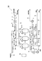
図2は、第1実施形態に係る蒸気生成器を含むシステム100の構成を示す。図3は、第1実施形態に係る蒸気生成器の断面図を示す。
<First Embodiment>
<< Configuration of Steam Generator >>
FIG. 2 shows a configuration of a
第1実施形態に係るシステム100は、蒸気生成器4、給水ポンプ5、温水供給管11、蒸気供給管12、圧縮空気供給管13、再生空気供給管9、真空排気管16、排水管14、排気管15、制御装置20等を備える。
A
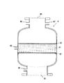
蒸気生成器4(本発明のゼオライト収容部に相当する)は、内部にゼオライトを収容する。図3に示すように、蒸気生成器4は、粒状のゼオライトが充填されたゼオライト層41の下部に設けられ、ゼオライト層41を受ける下金網42、ゼオライト層41の上部に設けられ、再生時のゼオライトの飛散を防止する上金網43、供給される温水を受け入れると共に再生空気を排出する供給口兼再生空気排出口45、ゼオライトを再生するために送り込まれる再生空気を受け入れる再生空気供給口46、生成した蒸気を排出する生成蒸気の排出口47、および圧力センサや温度センサなどの取り付け口48を備える。第1実施形態に係る蒸気生成器4は、所謂第1種圧力容器である。蒸気生成器4では、供給される温水がゼオライトに吸着され、吸着熱によって蒸気が生成される。
The steam generator 4 (corresponding to the zeolite accommodating part of the present invention) accommodates zeolite inside. As shown in FIG. 3, the
給水ポンプ5は、温水が流れる温水供給管11に設けられ、50〜100℃の温水(排温水)を圧送する。温水供給管11は、一端が鉄鋼施設や石油化学施設からの温水(排温水)が流れる配管(図示せず)と接続され、温水供給管11の途中で分岐し、他端が蒸気生成器4(4−1,4−2,4−3)の下部の供給口兼再生空気排出口45と接続されている。温水供給管11には、給水ポンプ5に加えて、給水ポンプ5の下流側に温水を加温する温水の加温装置6、蒸気生成器4(4−1,4−2,4−3)への給水量を調整自在な給水弁23−1,23−2,23−3が設けられている。給水ポンプ5、温水供給管11、給水弁23−1,23−2,23−3は、本発明の温水供給部の機能を担う。
The
蒸気供給管12は、蒸気生成器4で生成された蒸気が流れ、蒸気生成器4の外部に蒸気を利用する利用機器等や、蒸気を利用可能な施設等に供給する。蒸気供給管12は、一端が各蒸気生成器4−1,4−2,4−3の上部の生成蒸気の排出口47と接続され、蒸気供給管12が合流し、他端は蒸気を利用可能な利用機器等や施設等(シャワー室、サウナ、殺菌室など)に接続され、生成された蒸気が再生エネルギーとして利用される。蒸気供給管12の接続先は、蒸気を利用できればよく、利用機器や施設等に限定されない。排出された蒸気は、例えば、製鉄所におけるCO2分離に用いることができる。蒸気供給管1
2には、各蒸気生成器4−1,4−2,4−3の近傍(合流前の蒸気供給管)に蒸気供給弁21−1,21−2,21−3が設けられ、蒸気生成器4で生成された蒸気の供給、非供給の切り替えが可能である。蒸気供給管12、蒸気供給弁21−1,21−2,21−3は、本発明の蒸気排気部の機能を担う。
The steam supplied from the
2, steam supply valves 21-1, 21-2 and 21-3 are provided in the vicinity of the steam generators 4-1, 4-2 and 4-3 (steam supply pipes before joining) to generate steam. It is possible to switch between supply and non-supply of steam generated in the
圧縮空気供給管13は、コンプレッサ(図示せず)等で圧縮された空気が流れ、圧縮された空気を各蒸気生成器4−1,4−2,4−3へ供給する。圧縮空気供給管13は、一端が図示しないコンプレッサ等に接続され、他端が各蒸気生成器4−1,4−2,4−3の上部の再生空気供給口46に接続されている。圧縮空気供給管13には、パージ空気弁26−1,26−2,26−3が設けられている。
The compressed
再生空気供給管9は、温度と湿度が調整され、ゼオライトを再生するための空気(本発明の乾燥空気に相当する)が流れ、温度と湿度が調整された空気を各蒸気生成器4−1,4−2,4−3へ供給する。再生空気供給管9は、一端が送風機1に接続され、分岐後、他端が各蒸気生成器4−1,4−2,4−3の上部の再生空気供給口46に接続されている。第1実施形態では、各蒸気生成器4−1,4−2,4−3側の再生空気供給管9(分
岐後の再生空気供給管9の一部)と各蒸気生成器4−1,4−2,4−3側の圧縮空気供給管13(分岐後の圧縮空気供給管13の一部)とが共通配管となっている。再生空気供給管9には、送風機1の下流側に、再生空気供給管9を流れる空気を除湿する除湿機2が配置され、送風機1の下流側に、再生空気供給管9を流れる空気を加温する再生空気の加温装置3が設けられている。また、再生空気供給管9のうち、分岐後の再生空気供給管9には、更に再生空気弁24−1,24−2,24−3が設けられている。再生空気供給管9、送風機1、再生空気弁24−1,24−2,24−3は、本発明の乾燥空気供給部の機能を担う。また、除湿機2は、本発明の乾燥空気の湿度調整部に相当する。また、再生空気の加温装置3は、本発明の乾燥空気の温度調整部に相当する。
The regeneration air supply pipe 9 is adjusted in temperature and humidity, flows air for regenerating zeolite (corresponding to the dry air of the present invention), and the steam and generator 4-1 are supplied with the adjusted temperature and humidity. , 4-2, 4-3. One end of the regenerative air supply pipe 9 is connected to the blower 1, and after branching, the other end is connected to a regenerative
真空排気管16は、各蒸気生成器4−1,4−2,4−3から真空引きされた空気が流れる。真空排気管16は、一端が各蒸気生成器4−1,4−2,4−3の下部の供給口兼再生空気排出口45に夫々接続され、合流後、他端が各蒸気生成器4−1,4−2,4−3の外部に開放されている。真空排気管16のうち、合流後の真空排気管16には、真空排気管のポンプ7が設けられ、合流前の真空排気管16には真空排気弁25−1,25−2,25−3が設けられている。真空排気管16、真空排気管のポンプ7、及び真空排気弁25−1,25−2,25−3は、本発明の脱気部の機能を担う。
In the
排気管15は、蒸気生成後に各蒸気生成器4−1,4−2,4−3内に残留する空気を排出する際、排出する空気が流れる。排気管15は、一旦が各蒸気生成器4−1,4−2,4−3の供給口兼再生空気排出口45に接続され、合流後、他端が各蒸気生成器4−1,4−2,4−3の外部に開放されている。合流前の排気管15には、排気弁22−1,22−2,22−3が設けられている。
When exhausting the air remaining in each steam generator 4-1, 4-2, 4-3 after steam generation, the
排水管14は、蒸気生成後に各蒸気生成器4−1,4−2,4−3内に残留する温水を排出する際、排出する温水が流れる。排水管14は、一端が各蒸気生成器4−1,4−2,4−3の供給口兼再生空気排出口45に接続され、合流後、他端が各蒸気生成器4−1,4−2,4−3の外部に開放されている。合流前の排水管14には、排水弁27−1,27−2,27−3が設けられている。
When draining the hot water remaining in the steam generators 4-1, 4-2, 4-3 after steam generation, the
制御装置20は、各蒸気生成器4−1,4−2,4−3内の温度情報、又は圧力情報等に基づいて、温水の供給のタイミングや再生空気の供給のタイミングなどを制御する。制御装置20は、CPU(中央処理演算装置)、メモリ、操作部、表示部等を備え、CPUがメモリに格納された制御プログラムを実行することで、温水の供給のタイミングや乾燥空気の供給のタイミングなどを制御する。制御装置20は、各蒸気生成器4−1,4−2,4−3の温度センサや圧力センサ(図3では図示せず)、給水ポンプ5、温水の加温装置6、コンプレッサ(図示せず)、送風機1、除湿機2、再生空気の加温装置3、真空排気管のポンプ7、電磁弁からなる各種弁(給水弁23−1,23−2,23−3、蒸気供給弁21−1,21−2,21−3、パージ空気弁26−1,26−2,26−3、再生空気弁24−1,24−2,24−3、真空排気弁25−1,25−2,25−3、排気弁22−1,22−2,22−3、排水弁27−1,27−2,27−3)等と電気的に接続されており、給水ポンプ5、温水の加温装置6、コンプレッサ(図示せず)、送風機1、除湿機2、再生空気の加温装置3、真空排気管のポンプ7、各種弁等の動作を制御する。なお、図3では、制御装置20によってすべての機器や各種弁を制御可能に構成されているが、各機器や各種弁に制御装置を設け、各機器や各種弁は、時間により動作を個別に制御するようにしてもよい。
The
<<動作例>>
図4は、第1実施形態に係る蒸気生成器を含むシステムにおける各種弁の開閉状態の一例を示す。図1で説明したように、第1実施形態に係る蒸気生成器では、予熱工程、吸着
工程、減圧工程、再生工程(脱着工程)が繰り返し行われる。図4では、吸着工程(図1の予熱工程、吸着工程に相当する)、排出工程(図1の減圧工程に相当する)、再生工程(図1の再生工程に相当する)、脱気工程(吸着工程に移行するための準備工程)に分け、各工程における各種弁の開閉状態と模式的な動作時間が示されている。
<< Operation example >>
FIG. 4 shows an example of the open / close state of various valves in the system including the steam generator according to the first embodiment. As described with reference to FIG. 1, in the steam generator according to the first embodiment, the preheating step, the adsorption step, the decompression step, and the regeneration step (desorption step) are repeatedly performed. In FIG. 4, an adsorption process (corresponding to the preheating process and the adsorption process in FIG. 1), a discharge process (corresponding to the decompression process in FIG. 1), a regeneration process (corresponding to the regeneration process in FIG. 1), and a deaeration process ( It is divided into preparatory steps for shifting to the adsorption step), and the open / close states of various valves and schematic operation times in each step are shown.
図4の上段に示す、蒸気生成器4−1を例にみると、各蒸気生成器4−1では、排出工程から始まり、再生工程、脱気工程、吸着工程と続き、以後、排出工程、再生工程、脱気工程、吸着工程が繰り返されている。 Taking the steam generator 4-1 shown in the upper part of FIG. 4 as an example, each steam generator 4-1 starts with a discharge process, continues with a regeneration process, a deaeration process, and an adsorption process. The regeneration process, degassing process, and adsorption process are repeated.
排出工程は、吸着工程後に行われ、排出工程では、排水弁27−1、パージ空気弁26−1はそれぞれ開、給水弁23−1、蒸気供給弁21−1、排気弁22−1、再生空気弁24−1、真空排気弁25−1が閉になる。その結果、圧縮空気が供給されながら蒸気生成器4−1内に残留する温水が排出される。排出工程が終了すると、再生工程へ進む。 The discharge process is performed after the adsorption process. In the discharge process, the drain valve 27-1 and the purge air valve 26-1 are opened, the water supply valve 23-1, the steam supply valve 21-1, the exhaust valve 22-1, and the regeneration. The air valve 24-1 and the vacuum exhaust valve 25-1 are closed. As a result, the hot water remaining in the steam generator 4-1 is discharged while the compressed air is supplied. When the discharging process is completed, the process proceeds to the regeneration process.
再生工程では、再生空気弁24−1、排気弁22−1はそれぞれ開、パージ空気弁26−1、真空排気弁25−1、給水弁23−1、排水弁27−1、蒸気供給弁24−1の各弁はそれぞれ閉である。再生空気は、送風機1で除湿機2に供給される。除湿機2では再生空気の露点が−20℃以下まで乾燥され、空気加温装置3に供給される。除湿機2は、例えばゼオライトなどの吸着材を添着したロータを備えたものである。再生空気が再生空気供給管9内、又はダクト(図示せず)内を流れる流速は、蒸気生成器4内の流速(1.5m/sec)に合わせて、再生空気供給管9内、又はダクトの径により設置することができる。蒸気生成器4内の流速は、例えば、蒸気生成器4内の流速が1.5m/secとなるように、送風機1をインバータ制御して所定の流速の再生空気を送風機1から供給し、蒸気供給弁21−1,21−2,21−3、排気弁22−1,22−2,22−3の各弁で風量を更に調整することができる。送風機1から供給する再生空気の所定の流速や、蒸気各弁による風量の調整は、再生空気供給管9やダクトの径や長さに応じて適宜設定することができる。また、蒸気生成器4内の流速は、送風機1を定出力運転とし、蒸気供給弁21−1,21−2,21−3、排気弁22−1,22−2,22−3の各弁を風量調整自在なダンパとして利用し、各蒸気生成器4内を流れる風量を調整してもよい。この場合は、送風機1から供給する再生空気の流速や、蒸気各弁による風量の調整は、再生空気供給管9やダクトの径や長さに応じて適宜設定することができる。空気加温装置3では再生空気は約120℃まで加温され蒸気生成器4−1に供給される。その結果、ゼオライトに吸着された吸着水が脱着され、ゼオライトが再生する。再生工程が終了すると、脱気工程へ進む。
In the regeneration process, the regeneration air valve 24-1 and the exhaust valve 22-1 are opened, the purge air valve 26-1, the vacuum exhaust valve 25-1, the water supply valve 23-1, the drain valve 27-1, and the
脱気工程では、再生空気弁24−1、排気弁22−1、蒸気供給弁21−1、給水弁23−1、パージ空気弁26−1、排水弁27−1の各弁はそれぞれ閉、真空排気弁25−1は開になり、真空ポンプ7により蒸気生成器4−1内が脱気される。脱気工程が終了すると、吸着工程へ進む。なお、再生工程の終了後、その都度脱気工程を行うことで、蒸気生成器4−1内に空気が混入することを抑制することができる。その結果、蒸気生成器4−1よりも下流側の配管や機器の腐食を抑制することができる。 In the deaeration process, the regeneration air valve 24-1, the exhaust valve 22-1, the steam supply valve 21-1, the water supply valve 23-1, the purge air valve 26-1, and the drain valve 27-1 are closed, The vacuum exhaust valve 25-1 is opened, and the inside of the steam generator 4-1 is deaerated by the vacuum pump 7. When the deaeration process is completed, the process proceeds to the adsorption process. In addition, after completion | finish of a reproduction | regeneration process, it can suppress that air mixes in the steam generator 4-1, by performing a deaeration process each time. As a result, corrosion of piping and equipment on the downstream side of the steam generator 4-1 can be suppressed.
吸着工程では、真空排気弁25−1、蒸気排気弁21−1、排気弁22−1、再生空気弁24−1、パージ空気弁26−1、排水弁27−1の各弁は閉、給水弁23−1は開になり、温水が給水ポンプ5により蒸気生成器4−1に給水される。この給水は、ゼオライト層41が浸かるまで、具体的には給水される温水がゼオライト層41の上端となる上金網43に達するまで行われる。給水の制御は、水位計によって行ってもよく、また、予め設定した時間によって行ってもよい。その結果、蒸気生成器4−1内において、ゼオライトが温水に浸漬される状態となり、温水がゼオライトに吸着され、吸着反応により水蒸気が生成される。その後、蒸気供給弁21−1が開になり、生成された水蒸気のみが蒸気供
給弁21−1より排出される。
In the adsorption process, the vacuum exhaust valve 25-1, the steam exhaust valve 21-1, the exhaust valve 22-1, the regeneration air valve 24-1, the purge air valve 26-1, and the drain valve 27-1 are closed and water is supplied. The valve 23-1 is opened and hot water is supplied to the steam generator 4-1 by the
蒸気生成器4−2は蒸気生成器4−1とタイミングをずらして動作し(図4の中段に示す)、さらに蒸気生成器4−3は蒸気生成器4−1、4−2とタイミングをずらして動作する(図4の下段に示す)。そして、各蒸気生成器4−1,4−2,4−3がタイミングをずらした状態で、かつ、それぞれ連続的に工程を繰り返すことにより、蒸気生成器を含むシステム100全体では、水蒸気が連続的に生成される。なお、生成された蒸気の温度は、出願人が試験装置を製作して試験した結果では、125〜155℃(平均140℃)となり、負荷側での利用に十分供され得ることが確認された。但し、上記の値は実験結果の一例にすぎず、生成される蒸気の温度は、より高温になるものと考えられる。
The steam generator 4-2 operates at a different timing from the steam generator 4-1 (shown in the middle part of FIG. 4), and the steam generator 4-3 is synchronized with the steam generators 4-1 and 4-2. The operation is shifted (shown in the lower part of FIG. 4). And by each steam generator 4-1, 4-2, 4-3 having shifted timing, and repeating a process continuously, respectively, in the
図5は、第1実施形態に係る蒸気生成器において、給水と蒸気排気の位置関係を示す。第1実施形態に係る蒸気生成器4では、温水がゼオライト層41の下部から給水され、生成した水蒸気がゼオライト層41の上部から排出される。
FIG. 5 shows the positional relationship between water supply and steam exhaust in the steam generator according to the first embodiment. In the
<<効果>>
以上説明した第1実施形態に係る蒸気生成器を含むシステム100では、蒸気生成器4内に充填されたゼオライトと給水ポンプ5によって圧送される温水(排温水)とが接して、その際に発生する吸着熱により水蒸気が生成される。生成された水蒸気は、140℃以上であり、製鉄所におけるCO2分離など、再生エネルギーとして利用することができる
。温水には、例えば、鉄鋼産業や石油化学産業において、従来回収されずに排気されていた50〜100℃の排温水が例示される。したがって第1実施形態に係る蒸気生成器を含むシステム100では、従来廃棄されていた排温水から水蒸気を生成することができる。また、従来、排温水の廃棄には、冷却塔で冷却するなど、別途エネルギーを用いなければならなかったが、第1実施形態に係る蒸気生成器を含むシステム100では、そのような廃棄のための無駄なエネルギーを用いる必要もない。また、本発明に係る蒸気生成装置で生成された水蒸気は、生産プロセス等で利用でき、従来廃棄していた温熱を高品質なエネルギーに転嫁できる。更に、第1実施形態に係る蒸気生成器を含むシステム100は、再生空気供給管9、送風機1、再生空気弁24−1,24−2,24−3、除湿機2、再生空気の加温装置3を備えることで、ゼオライトに吸着されている吸着水を効果的に脱着させることができる。その結果、ゼオライトの再生が促進され、連続的に水蒸気を生成することができる。また、各蒸気生成器4−1,4−2,4−3がタイミングをずらした状態で、かつ、それぞれ連続的に吸着工程、排出工程、再生工程、脱気工程を繰り返すことにより、蒸気生成器を含むシステム100全体では、水蒸気を連続的に生成することができる。
<< Effect >>
In the
また、第1実施形態に係る蒸気生成器を含むシステム100では、温水がゼオライト層41の下部から供給されるため、水平方向の温水の分布を均一にすることができる。また、ゼオライト層41の水平方向の断面から一様に生成された水蒸気は、ゼオライトの上部から排出することができる。
Moreover, in the
以下、他の実施形態について説明するが、第1実施形態と同様の構成について同一符号を付し、詳細な説明は割愛する。 Other embodiments will be described below, but the same components as those in the first embodiment will be denoted by the same reference numerals, and detailed description thereof will be omitted.
<第2実施形態>
図6は、第2実施形態に係る蒸気生成器の断面図を示す。第2実施形態に係る蒸気生成器4では、ゼオライト層41の上方に温水供給ノズル200が設けられ、生成蒸気の排出口47がゼオライト層41の下部に設けられている。ゼオライト層41の上方に配した温水供給ノズル200により温水が給水される。なお、温水を蒸気生成器4内に保持するため、例えば供給口兼再生空気排出口45の下流側近傍にバタフライ弁を設け、これを閉と
してもよい。また、例えば、蒸気生成器4−1を例に説明すると、排水弁27−1、真空排気弁25−1、排気弁22−1、給水弁23−1を閉とし、対処してもよい。生成された水蒸気は、ゼオライト層41の下部の生成蒸気の排出口47から排出される。その結果、生成された水蒸気と供給される温水との熱交換を抑制することができる。
Second Embodiment
FIG. 6 shows a cross-sectional view of a steam generator according to the second embodiment. In the
<第3実施形態>
図7は、第3実施形態に係る蒸気生成器の断面図を示す。第3実施形態に係る蒸気生成器4は、ゼオライト層41が垂直方向において、互いに間隔を空けて2段設けられている。各ゼオライト層41は、ゼオライト層41を受ける下金網42、ゼオライト層41の上部に設けられ、再生時のゼオライトの飛散を防止する上金網43、圧力センサや温度センサなどの取り付け口48が設けられている。下段のゼオライト層41は予熱用、上段のゼオライト層41は蒸気生成用であり、ゼオライト層41毎に機能が割り当てられている。温水は、供給口兼再生空気排出口45から、下方から上方に供給し、下段のゼオライト層41が浸かるように供給するとよい。下段のみ浸かるようにすることで少ない供給量でより高温の蒸気を生成することができる。すなわち、より効率よく水蒸気を生成することができる。なお、ゼオライト層41は、3段以上設けてもよい。また、上段と下段のゼオライト層41の間から再生空気を供給するようにしてもよい。この場合、ゼオライト層41が1段のみの場合と比較して、再生空気が通過するゼオライト層41の層厚が薄くなり、再生空気の送風動力を低減することができる。
<Third Embodiment>
FIG. 7 shows a cross-sectional view of a steam generator according to the third embodiment. In the
<第4実施形態>
図8は、第4実施形態に係る蒸気生成器を含むシステムの構成を示す。第4実施形態では、各蒸気生成器4−1,4−2,4−3に接続された蒸気供給管12から分岐した分岐管12−1,12−2,12−3が設けられている。分岐管12−1,12−2,12−3には、生成された水蒸気の一部が流れる。分岐管12−1,12−2,12−3は、一端が蒸気供給管12に接続され、他端が隣接する蒸気生成器4−2に温水を供給する温水供給管11に接続されている。また、分岐管12−1,12−2,12−3には、夫々予熱蒸気弁28−1,28−2,28−3が設けられている。
<Fourth embodiment>
FIG. 8 shows a configuration of a system including a steam generator according to the fourth embodiment. In the fourth embodiment, branch pipes 12-1, 12-2, 12-3 branched from the
図9は、第4実施形態に係る蒸気生成器を含むシステムにおける各種弁の開閉状態の一例を示す。第4実施形態に係る蒸気生成器を含むシステム100では、脱気工程の後に、予熱工程が追加されている。予熱工程では、予熱蒸気弁28−1,28−2,28−3が開となり、水蒸気の一部が吸着工程の開始段階にある蒸気生成器に供給される。
FIG. 9 shows an example of an open / close state of various valves in a system including a steam generator according to the fourth embodiment. In the
第4実施形態では、たとえば蒸気生成器4−1で生成された水蒸気の一部が吸着工程の開始段階にある蒸気生成器4−2に供給した後に給水される。そのため、水蒸気の一部を利用して、他の蒸気生成器のゼオライトを予熱することが可能となり、吸着能力を向上することができる。なお、第4実施形態のような運転(運転モード)では、並列に配置された蒸気生成器4廻りの管(例えば、蒸気生成器4−1に接続される分岐管12−1と蒸気生成器4−2に接続される排水管14)が直列接続される。また、第4実施形態のような運転では、ゼオライト層41が既定の加熱能力を発揮できなくなった状態、換言すると、吸着工程の終盤(吸着工程から減圧工程に切り替わる前)やゼオライト層41の吸着性能が落ちた状態で行われることが好ましい。上記のような、ゼオライト層41が既定の加熱能力を発揮できなくなった状態では、水蒸気の全てを予熱に用いるようにしてもよい。
In the fourth embodiment, for example, a part of the water vapor generated by the steam generator 4-1 is supplied to the steam generator 4-2 at the start stage of the adsorption process and then supplied. Therefore, it becomes possible to preheat the zeolite of another steam generator using a part of water vapor, and to improve the adsorption capacity. In the operation (operation mode) as in the fourth embodiment, the pipes around the
<第5実施形態>
図10Aは、第5実施形態に係る蒸気生成器について、温度センサの設置例を示す。図10Bは、第5実施形態に係る蒸気生成器について、再生工程を終了する際のゼオライトの温度と経過時間との関係を示す。図10Cは、第5実施形態に係る蒸気生成器について、再生工程を終了する際に行われる処理フローを示す。
<Fifth Embodiment>
FIG. 10A shows an installation example of a temperature sensor in the steam generator according to the fifth embodiment. FIG. 10B shows the relationship between the temperature of the zeolite and the elapsed time when the regeneration process is completed for the steam generator according to the fifth embodiment. FIG. 10C shows a processing flow performed when the regeneration process is completed for the steam generator according to the fifth embodiment.
第5実施形態に係る蒸気生成器4には、ゼオライト層41の温度を検知する温度センサ71が設けられている。制御装置20は、再生工程において、タイマで設定された時間(t)と温度センサ71が検出する温度(T)とに基づいて再生工程を終了する。具体的には、再生工程において、あらかじめタイマで設定された時間(t)が経過するか、若しくは、温度センサ71で検出された温度(T)が上昇後、所定温度になると、再生空気を供給する再生空気弁24−1,24−2,24−3が閉となるように制御される。ここで、図10Bに示すように、再生後の空気の温度は再生の前半は残留水の蒸発潜熱により再生空気温度が一時低下し、再生の進行とともに温度が上昇するといった挙動を示す。そこで、制御装置20は、ゼオライト層41の下部に設けられた温度センサ71により再生後の空気の温度を検出し、前述のタイマで設定された時間(t)のタイムアップまたは当該温度(T)のどちらかの条件を満足するときに再生工程が終了する。その結果、再生工程に要する時間の最適化を実現することができる。
The
<第6実施形態>
図11Aは、第6実施形態に係る蒸気生成器について、圧力センサの設置例を示す。図11Bは、第6実施形態に係る蒸気生成器について、減圧工程を終了する際の蒸気生成器内の圧力と経過時間との関係を示す。図11Cは、第6実施形態に係る蒸気生成器について、減圧工程を終了する際に行われる処理フローを示す。
<Sixth Embodiment>
FIG. 11A shows an installation example of a pressure sensor in the steam generator according to the sixth embodiment. FIG. 11B shows the relationship between the pressure in the steam generator and the elapsed time when the decompression step is finished for the steam generator according to the sixth embodiment. FIG. 11C shows a processing flow performed when the decompression step is finished for the steam generator according to the sixth embodiment.
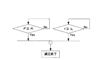
第6実施形態に係る蒸気生成器4には、蒸気生成器4内の圧力を検知する圧力センサ81が設けられている。制御装置20は、減圧工程において、タイマで設定された時間(t)と圧力センサ81が検出する圧力(P)とに基づいて減圧工程を終了する。具体的には、減圧工程において、あらかじめタイマで設定された時間(t)が経過するか、若しくは、圧力センサ81で検出された圧力(P)が低下後、所定圧力になると、蒸気生成器4内の水を排出する排水弁27−1,27−2,27−3が閉となるように制御される。ここで、図11Bに示すように、減圧中の蒸気生成器4内の圧力は、徐々に低下する挙動を示す。そこで、制御装置20は、圧力センサ81により蒸気生成器4内の圧力(P)を検出し、前述のタイマで設定された時間(t)のタイムアップまたは当該圧力(P)のどちらかの条件を満足するときに減圧工程が終了する。その結果、減圧工程に要する時間の最適化を実現することができる。
The
<第7実施形態>
図12Aは、第7実施形態に係る蒸気生成器について、温度センサの設置例を示す。図12Bは、第7実施形態に係る蒸気生成器について、給水工程を終了する際の蒸気生成器内の温度と経過時間との関係を示す。図12Cは、第7実施形態に係る蒸気生成器について、給水工程を終了する際に行われる処理フローを示す。給水工程とは、吸着工程において給水ポンプ5が温水を供給する工程を意味する。
<Seventh embodiment>
FIG. 12A shows an installation example of a temperature sensor in the steam generator according to the seventh embodiment. FIG. 12B shows the relationship between the temperature in the steam generator and the elapsed time when the water supply process is finished for the steam generator according to the seventh embodiment. FIG. 12C shows a processing flow performed when the water supply process is finished for the steam generator according to the seventh embodiment. The water supply process means a process in which the
第7実施形態に係る蒸気生成器4には、蒸気生成器4内の温度を検出する温度センサ72がゼオライト層41の上側に設けられている。制御装置20は、給水工程において、タイマで設定された時間と温度センサ72が検出する温度とに基づいて給水工程を終了する。具体的には、給水工程において、あらかじめタイマで設定された時間が経過するか、若しくは、温度センサ72で検出された温度が低下後、所定温度になると、給水弁23−1,23−2,23−3が閉となるように制御される。ここで、図12Bに示すように、給水中の蒸気生成器4内の温度は、上昇後、徐々に低下する挙動を示す。そこで、制御装置20は、温度センサ72により蒸気生成器4内の温度を検出し、前述のタイマのタイムアップまたは当該温度のどちらかの条件を満足するときに給水工程を終了する。その結果、給水工程に要する時間の最適化を実現することができる。
In the
<第8実施形態>
図13Aは、第8実施形態に係る蒸気生成器について、温度センサの設置例を示す。図13Bは、第8実施形態に係る蒸気生成器について、吸着工程を終了する際の蒸気生成器内の温度と経過時間との関係を示す。図13Cは、第8実施形態に係る蒸気生成器について、吸着工程を終了する際に行われる処理フローを示す。吸着工程の終了に関する処理は、第7実施形態で説明した給水工程の終了後に行われる。
<Eighth Embodiment>
FIG. 13A shows an installation example of a temperature sensor in the steam generator according to the eighth embodiment. FIG. 13B shows the relationship between the temperature in the steam generator and the elapsed time when the adsorption step is finished for the steam generator according to the eighth embodiment. FIG. 13C shows a processing flow performed when the adsorption process is completed for the steam generator according to the eighth embodiment. Processing related to the end of the adsorption step is performed after the end of the water supply step described in the seventh embodiment.
第8実施形態に係る蒸気生成器4には、蒸気生成器4内の温度を検出する温度センサ73が蒸気生成器4の最上部に設けられている。制御装置20は、吸着工程において、タイマで設定された時間(t)と温度センサ73が検出する温度(T)とに基づいて吸着工程を終了する。具体的には、吸着工程において、あらかじめタイマで設定された時間が経過するか、若しくは、温度センサ73で検出された温度が低下後、所定温度になると、蒸気供給弁21−1,21−2,21−3が閉となるように制御される。ここで、図13Bに示すように、給水中の蒸気生成器4内の温度は、上昇後、徐々に低下する挙動を示す。そこで、制御装置20は、温度センサ73により蒸気生成器4内の温度を検出し、前述のタイマで設定された時間(t)のタイムアップまたは当該温度(T)のどちらかの条件を満足するときに吸着工程を終了する。その結果、吸着工程に要する時間の最適化を実現することができる。
In the
<第9実施形態>
図14Aは、第9実施形態に係る蒸気生成器について、各種センサの設置例を示す。図14Aでは、例として、蒸気生成器4−1の周辺のみを示す。図14Bは、第9実施形態に係る蒸気生成器について、再生工程を終了する際の蒸気生成器内の露点、圧力、及び温度と経過時間との関係を示す。図14Cは、第9実施形態に係る蒸気生成器について、再生工程を終了する際に行われる処理フローを示す。
<Ninth Embodiment>
FIG. 14A shows an installation example of various sensors in the steam generator according to the ninth embodiment. In FIG. 14A, only the periphery of the steam generator 4-1 is shown as an example. FIG. 14B shows the relationship between the dew point, pressure, temperature, and elapsed time in the steam generator when the regeneration process is completed for the steam generator according to the ninth embodiment. FIG. 14C shows a processing flow performed when the regeneration process is finished for the steam generator according to the ninth embodiment.
第9実施形態に係る蒸気生成器4には、露点センサ92、差圧センサ91、温度センサ74が設けられている。露点センサ92は、排気管15に設けられ、排気される空気の露点を検出する。差圧センサ91は、再生空気供給管9と排気管15とを跨ぐ配管に設けられ、再生空気の供給前後の差圧を検出する。温度センサ71は、蒸気生成器4内のゼオライト層41よりも低い位置に設けられ、蒸気生成器4内の温度を検出する。制御装置20は、再生工程において、露点センサ92で検出された露点(TD)、差圧センサ91で検出された差圧(P)、温度センサ74で検出された温度(T)のうち少なくとも何れか一つが所定値となった場合に再生工程を終了する。具体的には、露点センサ92で検出された露点(TD)、差圧センサ91で検出された差圧(P)、温度センサ74で検出された温度(T)のうち少なくとも何れか一つが所定値になると、再生空気弁24−1,24−2,24−3が閉となるように制御される。ここで、図14B−1に示すように、再生工程中の露点(TD)は、徐々に低下する挙動を示す。また、図14B−2に示すように、再生工程中の差圧(P)は、徐々に上昇する挙動を示す。また、図14B−3に示すように、再生工程中の温度(T)は、低下後、徐々に上昇する挙動を示す。そこで、制御装置20は、露点センサ92で検出された露点(TD)、差圧センサ91で検出された差圧(P)、温度センサ74で検出された温度(T)のうち少なくとも何れか一つが所定値となった場合に再生工程を終了する。その結果、再生工程に要する時間の最適化を実現することができる。
The
<第10実施形態>
第10実施形態に係る蒸気生成器4は、ゼオライト層41に非吸着性充填物(ガラスビーズ、又はアルミナ)が充填されている。その他の点については、第1実施形態に係る蒸気生成器4の構成と同じである(図2、図3参照)。したがって、第10実施形態に係る蒸気生成器4においても、温水供給管11の他端は、蒸気生成器4(4−1,4−2,4
−3)の下部の供給口兼再生空気排出口45と接続されている。そのため、温水は、ゼオライト層41の下部から供給される。
<Tenth Embodiment>
In the
-3) and the lower supply port / regeneration
非吸着性充填物(ガラスビーズ、又はアルミナ)は、ゼオライト層41の温度変化に応じて、ゼオライト層41に対する充填比率を変更することができる。ゼオライト層41の温度変化の値は、実験等によって得ることができる。例えば、ゼオライト層41が温度上昇した際の最高温度の基準温度を定めるとともに基準温度に対する非吸着性充填物の基準充填量を定める。そして、実験によって得られたゼオライト層41の最高温度が基準温度よりも低い場合には、基準充填量よりも少ない量の非吸着性充填物を充填し、実験によって得られたゼオライト層41の最高温度が基準温度よりも高い場合には、基準充填量よりも多い量の非吸着性充填物を充填することができる。
The non-adsorptive filler (glass beads or alumina) can change the filling ratio with respect to the
ここで、図15Aは、比較例に係るゼオライト層の温度変化の一例のグラフを示す。図15Bは、図15Aのグラフにおける測定点を示す。測定点について、「NO.24」は、ゼオライト層の下面を意味し、「NO.16」は、ゼオライト層の下部を意味し、「NO.10」は、ゼオライト層の中間部を意味し、「NO.4」は、ゼオライト層の上部を示す。 Here, FIG. 15A shows a graph of an example of a temperature change of the zeolite layer according to the comparative example. FIG. 15B shows the measurement points in the graph of FIG. 15A. Regarding the measurement points, “NO.24” means the lower surface of the zeolite layer, “NO.16” means the lower part of the zeolite layer, “NO.10” means the middle part of the zeolite layer, “NO. 4” indicates the upper part of the zeolite layer.
比較例では、第10実施形態に係る蒸気生成器と異なり、ゼオライト層に非吸着性充填物が充填されていない。換言すると、比較例は、第1実施形態に係る蒸気生成器4に近い構成である。したがって、この比較例では、温水供給管の他端が、蒸気生成器の下部の供給口兼再生空気排出口と接続されており、温水は、ゼオライト層の下部から供給される。
In the comparative example, unlike the steam generator according to the tenth embodiment, the zeolite layer is not filled with the non-adsorbing filler. In other words, the comparative example has a configuration close to the
図15Aに示すように、比較例では、ゼオライト層の下部(NO.16)の最高温度は、約200℃であり、ゼオライト層の中間部(NO.10)の最高温度は、約250℃であり、ゼオライト層の上部(NO.4)の最高温度は、約275℃となっている。吸着工程開始前、換言すると脱気工程終了時のゼオライト層の温度は、何れも50℃前後であり、ゼオライト層の温度は、短時間で200℃以上まで急激に上昇することが確認された。 As shown in FIG. 15A, in the comparative example, the maximum temperature of the lower part (NO.16) of the zeolite layer is about 200 ° C., and the maximum temperature of the intermediate part (NO.10) of the zeolite layer is about 250 ° C. The maximum temperature of the upper part (NO.4) of the zeolite layer is about 275 ° C. It was confirmed that the temperature of the zeolite layer before the adsorption process started, in other words, at the end of the degassing process was around 50 ° C., and the temperature of the zeolite layer rapidly increased to 200 ° C. or more in a short time.
図16は、ラボ装置で行った、ゼオライト層の平均温度変化のグラフを示す。図17は、ラボ装置の概要を示す。ラボ装置200は、ゼオライト、又はゼオライト及び非吸着性充填物(ガラスビーズ、又はアルミナ)を含むゼオライト層201を収容する容器202、容器202、及び水203を収容する容器本体204、容器本体204の下部に設けられ、容器本体204内の水203を加熱して水蒸気を発生させるヒータ205を備える。ゼオライト、又はゼオライト及び非吸着性充填物を含むゼオライト層201の厚さは、8〜15mmである。このようなラボ装置200において、容器202の底部から約5mmの高さにおいて温度センサを6カ所設置(図17の「×」は、温度センサの設置位置の一部を示す)して、ゼオライト層201の温度を測定し、6カ所で測定された温度から、ゼオライトのみ、ゼオライト+ガラスビーズ、ゼオライト+アルミナ、夫々のゼオライト層201の平均温度を算出した。図16に示すように、ゼオライトのみのゼオライト層201の平均温度の最高温度は、約219℃である。これに対し、非吸着性充填物としてガラスビーズを含むゼオライト層201(ガラスビーズ充填)の平均温度の最高温度は、約196℃であり、非吸着性充填物としてアルミナを含むゼオライト層201(アルミナ充填)の平均温度の最高温度は、約186℃である。ゼオライト層201に非吸着性充填物(ガラスビーズ、又はアルミナ)を充填することで急激な温度上昇を抑制できることが確認できた。
FIG. 16 shows a graph of the average temperature change of the zeolite layer performed in the laboratory apparatus. FIG. 17 shows an outline of a laboratory apparatus. The
以上説明したように、ゼオライト層41に非吸着性充填物(ガラスビーズ、又はアルミナ)を充填することで、ゼオライト層41の急激な温度変化(本実施形態では温度上昇)を抑制することができる。その結果、ゼオライト層41の温度が高すぎる場合に懸念され
る、ゼオライト層41の吸着量の低下を抑制することができる。換言すると、ゼオライト層41の吸着量を向上することができ、より効率よく水蒸気を生成することができる。また、ゼオライト層41の急激な温度変化による、ゼオライト層41の劣化や破損の発生を抑制することができる。
As described above, by filling the
なお、上述したように、温水をゼオライト層41の下部から供給した場合、ゼオライト層41は、下部と比較して、上部の温度が高くなる。ゼオライト層41は、温水の供給位置などにより、領域毎に温度変化が異なる。したがって、最も温度が高くなる領域の温度変化に応じて、非吸着性充填物の充填比率を変えるようにしてもよい。また、ゼオライト層41を多段構成とし、非吸着性充填物の充填比率をゼオライト層41の段に応じて変えるようにしてもよい。これにより、吸着性能の低下や劣化が考えられるゼオライト層41の段(領域)のみ、非吸着性充填物を充填することができる。
In addition, as above-mentioned, when warm water is supplied from the lower part of the
以上、本発明の好適な実施形態を説明したが、本発明に係る蒸気生成器を含むシステムはこれらに限らず、可能な限りこれらの組合せを含むことができる。例えば、下金網42や上金網43に代えて、パンチング鋼板を用いてもよい。また、本発明に係る蒸気生成器を含むシステムは、様々な技術への適用が可能である。例えば、除湿機を連続使用するためには吸着材を再生する必要があるが、この再生のための加熱手段として例えば加熱用熱交換器に蒸気生成器4からの排水や蒸気供給管12中から分岐された蒸気、蒸気供給管12の供給先からの凝縮蒸気等を用いることができる。また、例えば、実施形態に係る蒸気生成器を含むシステムを医療機関に設置することで、実施形態に係るシステムからの排熱を用いて、蒸気を医療器具の殺菌や厨房での加熱に用いることもできる。
As mentioned above, although preferred embodiment of this invention was described, the system containing the steam generator which concerns on this invention is not restricted to these, It can include these combinations as much as possible. For example, instead of the
1・・・送風機
2・・・除湿機
3・・・再生空気の加温装置
4・・・蒸気生成器
5・・・給水ポンプ
6・・・温水の加温装置
7・・・真空排気管のポンプ
9・・・再生空気供給管
11・・・温水供給管
12・・・蒸気供給管
13・・・圧縮空気供給管
14・・・排水管
15・・・排気管
16・・・真空排気管
41・・・ゼオライト層
DESCRIPTION OF SYMBOLS 1 ...
Claims (4)
前記吸着材収容部に、50〜100℃の温水を供給する温水供給部と、
前記吸着材収容部の吸着材に前記温水を吸着させることで発生した蒸気を排出する蒸気排出部と、
前記吸着材収容部に、露点が−20℃以下の乾燥空気を供給し、前記吸着材に吸着された吸着水を脱着して当該吸着材を再生させる乾燥空気供給部と、を備え、
前記吸着材収容部は、多孔質体としての前記吸着材の他に、非吸着性充填物を含み、
前記吸着材収容部は、非吸着性充填物が充填される第一の部分と、前記第一の部分の充填比率と異なる充填比率で非吸着性充填物が充填される第二の部分と、を有する、
蒸気生成装置。 An adsorbent containing portion filled with a porous body inside,
A hot water supply unit for supplying hot water of 50 to 100 ° C. to the adsorbent storage unit;
A steam discharge section for discharging steam generated by adsorbing the hot water to the adsorbent in the adsorbent storage section;
A dry air supply unit that supplies dry air having a dew point of −20 ° C. or less to the adsorbent storage unit, desorbs adsorbed water adsorbed on the adsorbent, and regenerates the adsorbent;
In addition to the adsorbent as a porous body, the adsorbent container includes a non-adsorbing filler,
The adsorbent accommodating portion includes a first portion filled with a non-adsorbing filler, a second portion filled with a non-adsorbing filler at a filling ratio different from the filling ratio of the first portion, Having
Steam generator.
前記吸着材収容部に供給される50〜100℃の温水を受け入れる供給口と、
前記吸着材収容部の吸着材に前記温水を吸着させることで発生した蒸気を排出する排出口と、を備え、
前記吸着材収容部は、多孔質体としての前記吸着材の他に、非吸着性充填物を含み、
前記吸着材収容部は、非吸着性充填物が充填される第一の部分と、前記第一の部分の充填比率と異なる充填比率で非吸着性充填物が充填される第二の部分と、を有する、
吸着材収容器。 An adsorbent containing portion filled with a porous body inside ,
A supply port for receiving hot water of 50 to 100 ° C. supplied to the adsorbent storage unit;
A discharge port for discharging the steam generated by adsorbing the warm water to the adsorbent in the adsorbent containing section ,
The adsorbent containing portion, in addition to the adsorbent as a porous body, comprising the non-adsorbing filler,
The adsorbent accommodating portion includes a first portion filled with a non-adsorbing filler, a second portion filled with a non-adsorbing filler at a filling ratio different from the filling ratio of the first portion, Having
Adsorbent container.
前記吸着材収容部の吸着材に前記温水を吸着させることで発生した蒸気を排出する蒸気排出ステップと、
前記吸着材収容部に、露点が−20℃以下の乾燥空気を供給し、前記吸着材を再生させる乾燥空気供給ステップと、を備え、
前記吸着材収容部は、多孔質体としての前記吸着材の他に、非吸着性充填物を含み、
前記吸着材収容部は、非吸着性充填物が充填される第一の部分と、前記第一の部分の充填比率と異なる充填比率で非吸着性充填物が充填される第二の部分と、を有する、
蒸気生成方法。 A hot water supply step of supplying hot water of 50 to 100 ° C. to the adsorbent container filled with a porous body inside;
A steam discharge step for discharging steam generated by adsorbing the hot water to the adsorbent in the adsorbent container;
A drying air supply step of supplying dry air having a dew point of −20 ° C. or less to the adsorbent accommodating portion to regenerate the adsorbent;
In addition to the adsorbent as a porous body, the adsorbent container includes a non-adsorbing filler,
The adsorbent accommodating portion includes a first portion filled with a non-adsorbing filler, a second portion filled with a non-adsorbing filler at a filling ratio different from the filling ratio of the first portion, Having
Steam generation method.
前記吸着材収容部の吸着材に前記温水を吸着させることで発生した蒸気を排出する蒸気排出ステップと、を備え、
前記吸着材収容部は、多孔質体としての前記吸着材の他に、非吸着性充填物を含み、
前記吸着材収容部は、非吸着性充填物が充填される第一の部分と、前記第一の部分の充填比率と異なる充填比率で非吸着性充填物が充填される第二の部分と、を有する、
蒸気生成方法。 A hot water supply step of supplying hot water of 50 to 100 ° C. to the adsorbent container filled with a porous body inside;
A steam discharge step for discharging the steam generated by adsorbing the hot water to the adsorbent in the adsorbent container,
In addition to the adsorbent as a porous body, the adsorbent container includes a non-adsorbing filler,
The adsorbent accommodating portion includes a first portion filled with a non-adsorbing filler, a second portion filled with a non-adsorbing filler at a filling ratio different from the filling ratio of the first portion, Having
Steam generation method.
Priority Applications (1)
| Application Number | Priority Date | Filing Date | Title |
|---|---|---|---|
| JP2014074334A JP6443714B2 (en) | 2013-08-29 | 2014-03-31 | Steam generating apparatus, adsorbent container, and steam generating method |
Applications Claiming Priority (3)
| Application Number | Priority Date | Filing Date | Title |
|---|---|---|---|
| JP2013178565 | 2013-08-29 | ||
| JP2013178565 | 2013-08-29 | ||
| JP2014074334A JP6443714B2 (en) | 2013-08-29 | 2014-03-31 | Steam generating apparatus, adsorbent container, and steam generating method |
Publications (3)
| Publication Number | Publication Date |
|---|---|
| JP2015064192A JP2015064192A (en) | 2015-04-09 |
| JP2015064192A5 JP2015064192A5 (en) | 2017-05-18 |
| JP6443714B2 true JP6443714B2 (en) | 2018-12-26 |
Family
ID=52832209
Family Applications (1)
| Application Number | Title | Priority Date | Filing Date |
|---|---|---|---|
| JP2014074334A Active JP6443714B2 (en) | 2013-08-29 | 2014-03-31 | Steam generating apparatus, adsorbent container, and steam generating method |
Country Status (1)
| Country | Link |
|---|---|
| JP (1) | JP6443714B2 (en) |
Families Citing this family (4)
| Publication number | Priority date | Publication date | Assignee | Title |
|---|---|---|---|---|
| CN104197310B (en) * | 2014-08-22 | 2016-04-13 | 中盈长江国际新能源投资有限公司 | Solar water auxiliary regenerator device and the boiler of power plant solar energy hot water supplying system be made up of it |
| KR101808539B1 (en) * | 2016-07-25 | 2017-12-13 | 한국과학기술연구원 | Reactor for thermochemical heat storage |
| KR101783385B1 (en) | 2016-07-25 | 2017-10-10 | 한국과학기술연구원 | Reactor for thermochemical heat storage |
| CN108095158B (en) * | 2017-12-25 | 2023-08-25 | 太仓市宝马油脂设备有限公司 | Modulation system of energy-saving soybean tempering tower |
Family Cites Families (7)
| Publication number | Priority date | Publication date | Assignee | Title |
|---|---|---|---|---|
| WO1980002558A1 (en) * | 1979-05-21 | 1980-11-27 | W Thomas | Separating ethane from methane |
| US4301139A (en) * | 1979-06-21 | 1981-11-17 | Ames-Yissum Ltd. | Multilayer column chromatography specific binding assay method, test device and test kit |
| US4853004A (en) * | 1988-01-20 | 1989-08-01 | The Boc Group, Inc. | Method for densely packing molecular sieve adsorbent beds in a PSA system |
| JPH08192021A (en) * | 1995-01-12 | 1996-07-30 | Toshiba Corp | Air drying device |
| JP2004003832A (en) * | 2002-04-19 | 2004-01-08 | Denso Corp | Chemical thermal storage device |
| JP2005127683A (en) * | 2003-10-24 | 2005-05-19 | Atsushi Akisawa | Heat exchanger using heat transfer material having vapor adsorption/desorption function |
| JP4621816B2 (en) * | 2008-10-16 | 2011-01-26 | 時夫 大川 | Superheated steam generator, power generation ship and connecting robot |
-
2014
- 2014-03-31 JP JP2014074334A patent/JP6443714B2/en active Active
Also Published As
| Publication number | Publication date |
|---|---|
| JP2015064192A (en) | 2015-04-09 |
Similar Documents
| Publication | Publication Date | Title |
|---|---|---|
| JP6247788B1 (en) | Carbon dioxide separation and recovery system and method | |
| Jiang et al. | Comparative analysis on temperature swing adsorption cycle for carbon capture by using internal heat/mass recovery | |
| JP6443714B2 (en) | Steam generating apparatus, adsorbent container, and steam generating method | |
| BR112016015436B1 (en) | MULTIMONOLITE BEDS ROTARY MOVEMENT SYSTEM FOR THE REMOVAL OF CO2 FROM THE ATMOSPHERE | |
| JP2020044504A (en) | Carbon dioxide separation/recovery device | |
| JP2010503823A5 (en) | ||
| CN105032113B (en) | Process for capturing carbon dioxide in flue gas based on wet reclamation technology | |
| CN103429315A (en) | A method of cleaning a carbon dioxide containing gas, and a carbon dioxide purification system | |
| KR101991076B1 (en) | Adsorption Dehumidification System for Greenhouse | |
| WO2024047901A1 (en) | Carbon dioxide recovery apparatus and carbon dioxide recovery method | |
| US20240042371A1 (en) | Combined Thermal Energy Storage and Contaminant Removal | |
| JP2014094331A (en) | Co2 solid adsorbent system | |
| CN105032122B (en) | A kind of implementation method of tritiated apparatus for recovering | |
| RU2398616C2 (en) | Adsorption plant | |
| JP2021035654A (en) | Co2 separation method and facility | |
| JP5698172B2 (en) | Glove box | |
| CN203874651U (en) | Isobaric drying system | |
| JP2004036523A (en) | Exhaust gas treatment apparatus | |
| CN205700032U (en) | Exhaust-gas treatment activated carbon adsorption and regenerating unit | |
| JP2005103335A (en) | Thermal desorption type oxygen concentrating apparatus | |
| JP2019069417A (en) | Method and installation for recovering carbon dioxide from exhaust gas | |
| KR101466059B1 (en) | air dryer recycling apparatus using compressor waste heat | |
| JP6965169B2 (en) | Gas purification equipment and gas purification method | |
| JP2017089946A (en) | Heat storage system and operation method of heat storage system | |
| JP5579630B2 (en) | Carbon dioxide recovery system |
Legal Events
| Date | Code | Title | Description |
|---|---|---|---|
| A711 | Notification of change in applicant |
Free format text: JAPANESE INTERMEDIATE CODE: A711 Effective date: 20170327 |
|
| A521 | Request for written amendment filed |
Free format text: JAPANESE INTERMEDIATE CODE: A523 Effective date: 20170329 |
|
| A621 | Written request for application examination |
Free format text: JAPANESE INTERMEDIATE CODE: A621 Effective date: 20170329 |
|
| A521 | Request for written amendment filed |
Free format text: JAPANESE INTERMEDIATE CODE: A821 Effective date: 20170327 |
|
| A521 | Request for written amendment filed |
Free format text: JAPANESE INTERMEDIATE CODE: A821 Effective date: 20170329 |
|
| A521 | Request for written amendment filed |
Free format text: JAPANESE INTERMEDIATE CODE: A523 Effective date: 20170517 |
|
| A977 | Report on retrieval |
Free format text: JAPANESE INTERMEDIATE CODE: A971007 Effective date: 20180129 |
|
| A131 | Notification of reasons for refusal |
Free format text: JAPANESE INTERMEDIATE CODE: A131 Effective date: 20180206 |
|
| A521 | Request for written amendment filed |
Free format text: JAPANESE INTERMEDIATE CODE: A523 Effective date: 20180406 |
|
| A131 | Notification of reasons for refusal |
Free format text: JAPANESE INTERMEDIATE CODE: A131 Effective date: 20180522 |
|
| A521 | Request for written amendment filed |
Free format text: JAPANESE INTERMEDIATE CODE: A523 Effective date: 20180720 |
|
| A131 | Notification of reasons for refusal |
Free format text: JAPANESE INTERMEDIATE CODE: A131 Effective date: 20180731 |
|
| A521 | Request for written amendment filed |
Free format text: JAPANESE INTERMEDIATE CODE: A523 Effective date: 20181001 |
|
| TRDD | Decision of grant or rejection written | ||
| A01 | Written decision to grant a patent or to grant a registration (utility model) |
Free format text: JAPANESE INTERMEDIATE CODE: A01 Effective date: 20181016 |
|
| A61 | First payment of annual fees (during grant procedure) |
Free format text: JAPANESE INTERMEDIATE CODE: A61 Effective date: 20181115 |
|
| R150 | Certificate of patent or registration of utility model |
Ref document number: 6443714 Country of ref document: JP Free format text: JAPANESE INTERMEDIATE CODE: R150 |
|
| S111 | Request for change of ownership or part of ownership |
Free format text: JAPANESE INTERMEDIATE CODE: R313115 |
|
| R360 | Written notification for declining of transfer of rights |
Free format text: JAPANESE INTERMEDIATE CODE: R360 |
|
| S111 | Request for change of ownership or part of ownership |
Free format text: JAPANESE INTERMEDIATE CODE: R313115 |
|
| R370 | Written measure of declining of transfer procedure |
Free format text: JAPANESE INTERMEDIATE CODE: R370 |
|
| R350 | Written notification of registration of transfer |
Free format text: JAPANESE INTERMEDIATE CODE: R350 |
|
| R250 | Receipt of annual fees |
Free format text: JAPANESE INTERMEDIATE CODE: R250 |
|
| R250 | Receipt of annual fees |
Free format text: JAPANESE INTERMEDIATE CODE: R250 |
|
| R250 | Receipt of annual fees |
Free format text: JAPANESE INTERMEDIATE CODE: R250 |