JP6442509B2 - Swivel joint - Google Patents
Swivel joint Download PDFInfo
- Publication number
- JP6442509B2 JP6442509B2 JP2016539214A JP2016539214A JP6442509B2 JP 6442509 B2 JP6442509 B2 JP 6442509B2 JP 2016539214 A JP2016539214 A JP 2016539214A JP 2016539214 A JP2016539214 A JP 2016539214A JP 6442509 B2 JP6442509 B2 JP 6442509B2
- Authority
- JP
- Japan
- Prior art keywords
- leg
- bearing
- longitudinal direction
- swivel joint
- bearing surface
- Prior art date
- Legal status (The legal status is an assumption and is not a legal conclusion. Google has not performed a legal analysis and makes no representation as to the accuracy of the status listed.)
- Active
Links
- 230000001154 acute effect Effects 0.000 claims description 21
- 230000002093 peripheral effect Effects 0.000 claims description 7
- XLYOFNOQVPJJNP-UHFFFAOYSA-N water Substances O XLYOFNOQVPJJNP-UHFFFAOYSA-N 0.000 description 11
- 238000003466 welding Methods 0.000 description 9
- 230000009471 action Effects 0.000 description 4
- 238000003825 pressing Methods 0.000 description 4
- 238000000926 separation method Methods 0.000 description 4
- 238000002788 crimping Methods 0.000 description 3
- 239000000428 dust Substances 0.000 description 3
- 238000004519 manufacturing process Methods 0.000 description 3
- 239000011800 void material Substances 0.000 description 3
- 230000000903 blocking effect Effects 0.000 description 2
- 239000000356 contaminant Substances 0.000 description 2
- 230000000694 effects Effects 0.000 description 2
- 230000003466 anti-cipated effect Effects 0.000 description 1
- 230000008901 benefit Effects 0.000 description 1
- 238000005266 casting Methods 0.000 description 1
- 238000009826 distribution Methods 0.000 description 1
- 230000003993 interaction Effects 0.000 description 1
- 238000003754 machining Methods 0.000 description 1
- 238000000034 method Methods 0.000 description 1
- 238000005065 mining Methods 0.000 description 1
- 238000012986 modification Methods 0.000 description 1
- 230000004048 modification Effects 0.000 description 1
- 230000008439 repair process Effects 0.000 description 1
Images


Classifications
-
- E—FIXED CONSTRUCTIONS
- E04—BUILDING
- E04H—BUILDINGS OR LIKE STRUCTURES FOR PARTICULAR PURPOSES; SWIMMING OR SPLASH BATHS OR POOLS; MASTS; FENCING; TENTS OR CANOPIES, IN GENERAL
- E04H12/00—Towers; Masts or poles; Chimney stacks; Water-towers; Methods of erecting such structures
- E04H12/18—Towers; Masts or poles; Chimney stacks; Water-towers; Methods of erecting such structures movable or with movable sections, e.g. rotatable or telescopic
- E04H12/187—Towers; Masts or poles; Chimney stacks; Water-towers; Methods of erecting such structures movable or with movable sections, e.g. rotatable or telescopic with hinged sections
-
- E—FIXED CONSTRUCTIONS
- E04—BUILDING
- E04H—BUILDINGS OR LIKE STRUCTURES FOR PARTICULAR PURPOSES; SWIMMING OR SPLASH BATHS OR POOLS; MASTS; FENCING; TENTS OR CANOPIES, IN GENERAL
- E04H12/00—Towers; Masts or poles; Chimney stacks; Water-towers; Methods of erecting such structures
- E04H12/32—Flagpoles
-
- F—MECHANICAL ENGINEERING; LIGHTING; HEATING; WEAPONS; BLASTING
- F16—ENGINEERING ELEMENTS AND UNITS; GENERAL MEASURES FOR PRODUCING AND MAINTAINING EFFECTIVE FUNCTIONING OF MACHINES OR INSTALLATIONS; THERMAL INSULATION IN GENERAL
- F16L—PIPES; JOINTS OR FITTINGS FOR PIPES; SUPPORTS FOR PIPES, CABLES OR PROTECTIVE TUBING; MEANS FOR THERMAL INSULATION IN GENERAL
- F16L27/00—Adjustable joints, Joints allowing movement
- F16L27/02—Universal joints, i.e. with mechanical connection allowing angular movement or adjustment of the axes of the parts in any direction
Description
本発明は、照明柱及び類似の構造で使用されるスイベルジョイントに関する。スイベルジョイントは、高さ2mを越える照明柱、又は簡単に届かない位置に照明を有する照明柱で使用されることが予測される。スイベルジョイントは、旗竿などの他の柱で、又は防犯カメラの架台などの高くした細長い構造で使用されることがあると予期される。 The present invention relates to swivel joints used in lighting columns and similar structures. Swivel joints are expected to be used in lighting columns that are over 2m in height or that have lighting in locations that are not easily reached. It is anticipated that the swivel joint may be used in other pillars, such as flagpoles, or in elevated elongated structures, such as security camera mounts.
Swivelpole(商標)は、その内容を参照により本明細書に組み込む、WO0125687として公開された国際特許出願に記載されている。この製品は、その長さに沿ってスイベルジョイントを有する照明柱から成る。スイベルジョイントによって、これまで利用可能であったよりも安全で簡単な照明の交換及び修理が可能になっている。 Swivelpole ™ is described in an international patent application published as WO0125687, the contents of which are incorporated herein by reference. This product consists of a lighting column with a swivel joint along its length. The swivel joint allows for safer and easier lighting replacement and repair than previously available.
Swivelpole(商標)は、大きな成功を収めており、多くの工業設備、採掘設備、及び石油ガス設備における重要な安全策となっている。それでもなお、製品の製造及び使用の両方において改善が可能であろうと考えられている。 Swivelpole (TM) has been very successful and has become an important safety measure in many industrial, mining and oil and gas facilities. Nonetheless, it is believed that improvements can be made in both product manufacture and use.
Swivelpole(商標)は、管材上に平板を精密に溶接することを要する。かかる溶接は、高価な機器に加えて相当な熟練を要する。未熟な溶接は、平板の歪みに結び付き、結果として性能が悪いジョイントにつながる恐れがある。溶接を伴わずに、例えば鋳造及び機械加工によって形成することができる、ジョイントを有するのが望ましいと考えられる。Swivelpole(商標)はかかる方法によって簡単に形成することができない。 Swivelpole ™ requires that a flat plate be precisely welded onto the tubing. Such welding requires considerable skill in addition to expensive equipment. Inexperienced welding can lead to flat plate distortion and can result in poor performance joints. It would be desirable to have a joint that can be formed, for example, by casting and machining without welding. Swivelpole ™ cannot be easily formed by such a method.
それに加えて、設計の性質により、Swivelpole(商標)は、水及び埃が入る恐れがあるオープンジョイントを含む。いくつかの用途では、このことは問題である。 In addition, due to the nature of the design, the Swivelpole (TM) includes an open joint that can get into water and dust. In some applications this is a problem.
本発明は、特に、スイベルジョイントの主要な概念を保持したまま、より簡単な製造を可能にするため、これまでのSwivelpole(商標)設計のいくつかの特徴を改善しようとするものである。 The present invention seeks to improve several features of previous Swivelpole (TM) designs, in particular in order to allow easier manufacturing while retaining the main concept of swivel joints.
本発明の一つの態様によれば、第1の部材と、第2の部材と、少なくとも一つの支承部材とを含む、スイベルジョイントが提供され、第1の部材は第1の脚体と関連付けられ、第1の脚体は長手方向を有し、第1の部材は第1の脚体の長手方向に対して鋭角で配向された環状基部を有し、基部は外周縁を有し、第2の部材は第2の脚体と関連付けられ、第2の脚体は長手方向を有し、第2の部材は、第1の部材の環状基部の周りに位置してスイベルジョイントの外表面を画成するように配置された外壁を含み、第1の部材は、スイベルジョイントの外表面の内側に位置する支承面を有し、支承部材は調節可能な接続手段によって第2の部材に接続され、支承部材は第2の部材の外壁内に位置し、支承部材の支承面は第1の部材の支承面に対向し、調節可能な接続手段によって、支承部材の支承面及び第1の部材の支承面が摩擦係合して、第2の部材に対する第1の部材の回転移動を制限する第1の構成と、第1の部材に対する第2の部材の回転が許容される第2の構成との間で、支承部材及び第2の部材の相対移動が可能になる。 According to one aspect of the present invention, a swivel joint is provided that includes a first member, a second member, and at least one bearing member, the first member being associated with the first leg. The first leg has a longitudinal direction, the first member has an annular base oriented at an acute angle with respect to the longitudinal direction of the first leg, the base has an outer peripheral edge, The second member is associated with the second leg, the second leg has a longitudinal direction, and the second member is positioned around the annular base of the first member to define the outer surface of the swivel joint. The first member has a bearing surface located inside the outer surface of the swivel joint, the bearing member being connected to the second member by adjustable connecting means, The bearing member is located in the outer wall of the second member, the bearing surface of the bearing member is opposite the bearing surface of the first member, and adjustable connecting means By means of this, the first structure that frictionally engages the support surface of the support member and the support surface of the first member to limit the rotational movement of the first member relative to the second member, and the second configuration relative to the first member The relative movement of the support member and the second member becomes possible with the second configuration in which the rotation of the member is allowed.
本発明の第2の態様によれば、第1の部材と、第2の部材と、少なくとも一つの支承部材とを含む、スイベルジョイントが提供され、第1の部材は第1の脚体と関連付けられ、第1の脚体は長手方向を有し、第1の部材は第1の脚体の長手方向に対して鋭角で配向された環状基部を有し、基部は外周縁を有し、第2の部材は第2の脚体と関連付けられ、第2の脚体は長手方向を有し、第2の部材は、第1の部材の環状基部の周りに位置してスイベルジョイントの外表面を画成するように配置された外壁を含み、第2の部材は、スイベルジョイントの外表面の内側に位置する支承面を有し、支承部材は調節可能な接続手段によって第1の部材に接続され、支承部材は第2の部材の外壁内に位置し、支承部材の支承面は第2の部材の支承面に対向し、調節可能な接続手段によって、支承部材の支承面及び第2の部材の支承面が摩擦係合して、第2の部材に対する第1の部材の回転移動を制限する第1の構成と、第1の部材に対する第2の部材の回転が許容される第2の構成との間で、支承部材及び第1の部材の相対移動が可能になる。 According to a second aspect of the present invention, there is provided a swivel joint comprising a first member, a second member, and at least one support member, wherein the first member is associated with the first leg. The first leg has a longitudinal direction, the first member has an annular base oriented at an acute angle with respect to the longitudinal direction of the first leg, the base has an outer periphery, The second member is associated with the second leg, the second leg has a longitudinal direction, and the second member is positioned around the annular base of the first member and defines the outer surface of the swivel joint. The second member has a bearing surface located inside the outer surface of the swivel joint, the bearing member being connected to the first member by an adjustable connecting means. The bearing member is located in the outer wall of the second member, the bearing surface of the bearing member being opposite the bearing surface of the second member, and adjustable connecting means Accordingly, the first structure that restricts the rotational movement of the first member relative to the second member by frictional engagement between the support surface of the support member and the support surface of the second member, and the second configuration relative to the first member. The support member and the first member can be relatively moved with respect to the second configuration in which the rotation of the member is allowed.
本発明の第3の態様によれば、第1の部材と、第2の部材と、少なくとも一つの支承部材とを含む、スイベルジョイントが提供され、第1の部材は第1の脚体と関連付けられ、第1の脚体は長手方向を有し、第1の部材は基部を有し、基部は外周縁を有し、外周縁は面内に位置し、面は動作軸に垂直であり、動作軸はオフセット角で第1の脚体の長手方向軸線に対して角度を付けられ、第2の部材は第2の脚体と関連付けられ、第2の脚体は長手方向を有し、第2の部材は、第1の部材の環状基部の周りに位置してスイベルジョイントの外表面を画成するように配置された外壁を含み、第1の部材は、スイベルジョイントの外表面の内側に位置する支承面を有し、支承部材は調節可能な接続手段によって第2の部材に接続され、支承部材は第2の部材の外壁内に位置し、支承部材の支承面は第1の部材の支承面に対向し、調節可能な接続手段によって、支承部材の支承面及び第1の部材の支承面が摩擦係合して、第2の部材に対する第1の部材の回転移動を制限する第1の構成と、第1の部材に対する第2の部材の回転が許容される第2の構成との間で、支承部材及び第1の部材の相対移動が可能になる。 According to a third aspect of the present invention, there is provided a swivel joint comprising a first member, a second member, and at least one support member, wherein the first member is associated with the first leg. The first leg has a longitudinal direction, the first member has a base, the base has an outer periphery, the outer periphery is located in a plane, and the surface is perpendicular to the operation axis; The motion axis is angled with respect to the longitudinal axis of the first leg by an offset angle, the second member is associated with the second leg, the second leg has a longitudinal direction, The second member includes an outer wall positioned about the annular base of the first member and positioned to define an outer surface of the swivel joint, the first member being located on the inner side of the outer surface of the swivel joint. Having a bearing surface located, the bearing member being connected to the second member by means of adjustable connecting means, the bearing member being located within the outer wall of the second member The supporting surface of the supporting member faces the supporting surface of the first member, and the supporting surface of the supporting member and the supporting surface of the first member are frictionally engaged by the adjustable connecting means, so that the second member Between the first configuration that restricts the rotational movement of the first member relative to the first configuration and the second configuration that allows rotation of the second member relative to the first member. It becomes possible to move.
有利には、支承部材の支承面と第1又は第2の部材の支承面との間の支承接続は、ジョイントの内側に位置し、水又は埃の進入から保護される。 Advantageously, the bearing connection between the bearing surface of the bearing member and the bearing surface of the first or second member is located inside the joint and is protected from the entry of water or dust.
好ましくは、第2の部材の外壁又はスカート、及び第1の部材の環状基部の周囲が組み合わされて、第2の構成のときに第2の部材が第1の部材に対して周りで回転することができる、円形トラックが画成される。 Preferably, the outer wall or skirt of the second member and the circumference of the annular base of the first member are combined so that the second member rotates about the first member when in the second configuration A circular track can be defined that can.
第1又は第2の部材の支承面は環状であることが好ましい。最も好ましい実施形態では、第1又は第2の部材の支承面は環状溝によって形成される。 The bearing surface of the first or second member is preferably annular. In the most preferred embodiment, the bearing surface of the first or second member is formed by an annular groove.
環状溝は、円筒状の中央表面と二つの円錐台形の外表面という三つの表面から形成されてもよい。 The annular groove may be formed from three surfaces: a cylindrical central surface and two frustoconical outer surfaces.
調節可能な接続手段はねじ付きボルトを含んでもよく、ボルトのねじ込み移動によって第1及び第2の構成の間での移動が引き起こされる。 The adjustable connecting means may comprise a threaded bolt, and the screwing movement of the bolt causes movement between the first and second configurations.
最も好ましい実施形態では、ボルトは環状基部に対してほぼ接線方向であってもよい。代替実施形態では、ボルトは環状基部に対してほぼ径方向であってもよい。更なる代替実施形態では、ボルトは環状基部に対して軸線方向であるか、又は軸線方向に対してオフセットされてもよい。 In the most preferred embodiment, the bolt may be substantially tangential to the annular base. In an alternative embodiment, the bolt may be substantially radial with respect to the annular base. In further alternative embodiments, the bolt may be axial with respect to the annular base or may be offset with respect to the axial direction.
支承部材が、ボルト上のねじ山と係合するように配置された、雌ねじ付きの本体部分を含むことが好ましい。本体部分が支承部材の係合部分と一体であり、係合部分が支承面を含むことが好ましい。 Preferably, the bearing member includes a female threaded body portion arranged to engage a thread on the bolt. Preferably, the body portion is integral with the engagement portion of the bearing member, and the engagement portion includes a bearing surface.
支承部材は、本体部分及び係合部分をそれぞれ有する、二つの係合部材を含んでもよい。好ましい実施形態では、一つの係合部材のみの本体部分が雌ねじ付きである。二つの係合部材は、係合部材を付勢して相互から離すように作用してもよい、ばねなどの弾性付勢手段によって分離されてもよい。 The bearing member may include two engaging members each having a body portion and an engaging portion. In a preferred embodiment, the body portion with only one engagement member is internally threaded. The two engaging members may be separated by elastic biasing means, such as a spring, which may act to bias the engaging members away from each other.
あるいは、支承部材は、第1の構成と第2の構成との間で枢動するように配置されてもよい。 Alternatively, the bearing member may be arranged to pivot between the first configuration and the second configuration.
本発明の第4の態様によれば、第1の部材と、第2の部材と、支承部材とを含むスイベルジョイントが提供され、第1の部材は第1の脚体と関連付けられ、第1の脚体は長手方向を有し、第1の部材は中空本体部分を有し、第1の部材は第1の脚体の長手方向に対して鋭角で配向された支承面を有し、支承面は中空本体部分に面し、第2の部材は第2の脚体と関連付けられ、第2の脚体は長手方向を有し、支承部材は調節可能な接続手段によって第2の部材に接続され、支承部材は第1の脚体の長手方向に対して鋭角で配向された支承面を有し、支承部材は第1の部材の中空本体部分内に位置し、支承部材の支承面は第1の部材の支承面に対向し、調節可能な接続手段によって、支承部材の支承面及び第1の部材の支承面が摩擦係合して、第2の部材に対する第1の部材の回転移動を制限する第1の構成と、第1の部材に対する第2の部材の回転が許容される第2の構成との間で、支承部材及び第2の部材の相対移動が可能になる。 According to a fourth aspect of the present invention, there is provided a swivel joint that includes a first member, a second member, and a support member, wherein the first member is associated with the first leg, The leg has a longitudinal direction, the first member has a hollow body portion, the first member has a bearing surface oriented at an acute angle with respect to the longitudinal direction of the first leg, The face faces the hollow body part, the second member is associated with the second leg, the second leg has a longitudinal direction, and the bearing member is connected to the second member by an adjustable connecting means The bearing member has a bearing surface oriented at an acute angle with respect to the longitudinal direction of the first leg, the bearing member is located in the hollow body portion of the first member, and the bearing surface of the bearing member is The first member with respect to the second member is frictionally engaged with the bearing surface of the bearing member and the bearing surface of the first member by an adjustable connecting means facing the bearing surface of the first member. The support member and the second member can be moved relative to each other between the first configuration that restricts the rotational movement of the second member and the second configuration that allows the rotation of the second member relative to the first member. .
第1の部材の支承面は環状であってもよい。中空本体部分の外縁部に環状の肩部として形成されてもよい。 The bearing surface of the first member may be annular. It may be formed as an annular shoulder at the outer edge of the hollow body portion.
支承部材は環状であってもよい。一実施形態では、支承部材の支承面は支承部材の外側環状リングである。支承部材は、外側環状リングの内側に位置する接続手段受入れアパーチャを含んでもよい。 The support member may be annular. In one embodiment, the bearing surface of the bearing member is the outer annular ring of the bearing member. The bearing member may include a connection means receiving aperture located inside the outer annular ring.
接続手段受入れアパーチャは雌ねじ付きであってもよい。接続手段は、受入れアパーチャ内に受け入れられるように配置された複数の雄ねじ付きボルトによって形成されてもよい。 The connecting means receiving aperture may be internally threaded. The connecting means may be formed by a plurality of male threaded bolts arranged to be received within the receiving aperture.
ボルトはスイベルジョイントの周りで角度を付けて離隔されてもよい。一実施形態では、接続手段は、120°離隔された三つのかかるボルトによって形成されてもよい。 The bolts may be spaced at an angle around the swivel joint. In one embodiment, the connecting means may be formed by three such bolts separated by 120 °.
ボルトは支承面に垂直であってもよい。一実施形態では、ボルトは垂直から鋭角で、好ましくは22.5°など、15°〜30°でオフセットされる。この実施形態では、支承部材は、135°などの鈍い円錐角を有する、円錐台形である面を有する環状の接続手段受入れ部分を含んでもよい。 The bolt may be perpendicular to the bearing surface. In one embodiment, the bolts are offset from vertical by an acute angle, preferably between 15 ° and 30 °, such as 22.5 °. In this embodiment, the bearing member may include an annular connecting means receiving portion having a frustoconical surface with a blunt cone angle, such as 135 °.
この実施形態の好ましい形態では、第1の部材及び第2の部材の一方が円形の陥凹部を有し、第1の部材及び第2の部材の他方が円形の陥凹部内に位置する円形の突起を有し、調節可能な接続手段が円形の突起内を貫通する。 In a preferred form of this embodiment, one of the first member and the second member has a circular recess, and the other of the first member and the second member is a circular shape located in the circular recess. An adjustable connecting means having a protrusion penetrates through the circular protrusion.
スイベルジョイントは、補助係止ピンを受け入れるように配置された補助アパーチャを、第1の部材及び第2の部材に含んでもよい。補助アパーチャは、第1及び第2の部材の少なくとも一方の外周縁から内側に延在する陥凹部として形成されてもよい。 The swivel joint may include an auxiliary aperture in the first member and the second member arranged to receive the auxiliary locking pin. The auxiliary aperture may be formed as a recess that extends inwardly from the outer peripheral edge of at least one of the first and second members.
本発明の第5の態様によれば、第1の部材と、第2の部材と、支承部材とを含むスイベルジョイントが提供され、第1の部材は長手方向で延在する第1の脚体と関連付けられ、第1の脚体は長手方向を有し、第1の部材は中空本体部分を有し、第1の部材は第1の脚体の長手方向に対して鋭角で配向された支承面を有し、支承面は第1の脚体に面し、第2の部材は長手方向で延在する第2の脚体と関連付けられ、第2の脚体は長手方向を有し、第1の部材及び第2の部材は接続環体に沿って交わるように配置され、支承部材は調節可能な接続手段によって第2の部材に接続され、支承部材は第1の脚体の長手方向に対して鋭角で配向された支承面を有し、支承部材は接続環体の内部に位置し、支承部材の支承面は第1の部材の支承面に対向し、調節可能な接続手段によって、支承部材の支承面及び第1の部材の支承面が摩擦係合して、第2の部材に対する第1の部材の回転移動を制限する第1の構成と、第1の部材に対する第2の部材の回転が許容される第2の構成との間で、支承部材及び第2の部材の相対移動が可能になる。 According to the fifth aspect of the present invention, there is provided a swivel joint including a first member, a second member, and a support member, the first member extending in the longitudinal direction. The first leg has a longitudinal direction, the first member has a hollow body portion, and the first member is a bearing oriented at an acute angle with respect to the longitudinal direction of the first leg. Having a surface, the bearing surface faces the first leg, the second member is associated with a second leg extending longitudinally, the second leg having a longitudinal direction, The first member and the second member are arranged so as to cross along the connection ring, the support member is connected to the second member by an adjustable connection means, and the support member is arranged in the longitudinal direction of the first leg. A bearing surface oriented at an acute angle to the bearing member, the bearing member being located inside the connecting ring, the bearing surface of the bearing member facing the bearing surface of the first member, by means of an adjustable connecting means A first configuration in which the support surface of the support member and the support surface of the first member are frictionally engaged to limit the rotational movement of the first member relative to the second member; and a second configuration relative to the first member The relative movement of the support member and the second member becomes possible with the second configuration in which the rotation of the member is allowed.
ジョイントを、第1及び第2の脚体それぞれの長手方向軸線が平行である主要配向へと回転させることができるのが好ましい。更に、この配向において、ジョイントの中心軸の周りに空隙が画成されることが好ましい。有利には、これによってケーブル及び類似の品目が中心軸に沿って中心に位置することが可能になる。 Preferably, the joint can be rotated to a primary orientation in which the longitudinal axes of each of the first and second legs are parallel. Furthermore, it is preferred that in this orientation a void is defined around the central axis of the joint. Advantageously, this allows cables and similar items to be centered along the central axis.
第2の部材に対する第1の部材の回転は、第1の脚体の長手方向軸線に対して鋭角で配設される回転軸を中心にして起こることが好ましい。 The rotation of the first member relative to the second member preferably occurs about a rotation axis disposed at an acute angle with respect to the longitudinal axis of the first leg.
鋭角は30°〜60°であってもよく、最も好ましくは約45°である。 The acute angle may be between 30 ° and 60 °, most preferably about 45 °.
スイベルジョイントは、物品を基部位置から離して配置するため、細長い部材内で有効に配備されてもよい。少なくとも1.5mの長さを有する細長い部材において、特に長さが2mを上回る場合に有用であり得ると考えられる。細長い部材は照明柱であってもよい。 The swivel joint may be effectively deployed within the elongate member to place the article away from the base position. It is believed that it may be useful for elongated members having a length of at least 1.5 m, especially when the length is greater than 2 m. The elongated member may be a lighting column.
本発明の好ましい実施形態を参照して、本明細書について更に記載するのが好都合であろう。他の実施形態が可能であり、結果として、以下の考察における特徴は本発明の上記記載の普遍性に取って代わるとは理解されないものとする。 It will be convenient to further describe the specification with reference to preferred embodiments of the invention. Other embodiments are possible, and as a result, the features in the following discussion should not be understood to replace the above-described universality of the present invention.
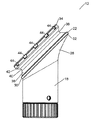
本発明の第1の実施形態について、第1の部材12、第2の部材14、及び支承部材16という三つの主要構成要素を有するスイベルジョイント10が示される、図1〜10を参照して記載する。
The first embodiment of the present invention will be described with reference to FIGS. 1-10, in which a swivel joint 10 is shown having three main components: a
第1の部材12は、長手方向で配向される第1の脚体18と関連付けられる。第1の脚体18は、圧締め又は溶接などの適切な手段によって柱(照明柱の基部など)に接続するように配置された円筒状スリーブを形成する、柱受入れアパーチャ20で終端する。
The
第2の部材14は、長手方向で配向される第2の脚体24と関連付けられる。第2の脚体24は、圧締め又は溶接などの適切な手段によって柱(照明柱の上側部分など)に接続するように配置された円筒状スリーブを形成する、柱受入れアパーチャ26で終端する。
The
配置は、スイベルジョイント10が図1に示されるような第1の位置にあるとき、第1の脚体18及び第2の脚体24の両方が垂直であることができ、共通の長手方向軸線に沿って位置合わせされるような配置である。
The arrangement is such that when the swivel joint 10 is in the first position as shown in FIG. 1, both the
第1の部材12は、先細の接続部分28によって第1の脚体18に接続される環状基部22を有する。
The
環状基部22は、第1の脚体18の長手方向軸線に対してある角度で配向される面を画成する。配向の角度は、第1の脚体18の長手方向軸線と基部22の面に垂直な線との間のオフセット角を規定することによって考慮されてもよい。オフセット角は鋭角である。図示される実施形態では、オフセット角は45°である。
The
環状基部22は、直径が第1の脚体18のほぼ二倍の円形である。環状基部22は、下面30が第1の脚体18によって画成される見かけの円筒に近く、上面32がこの見かけの円筒から離隔されるようにして位置決めされる。
The
第1の部材12は、基部22に平行であってそこから離隔された環状の外側リム34を有する。外側リム34は、直径が基部22の直径に類似した円形である。基部22及び外側リム34は、長手方向軸線に対してオフセット角で配向される、共通のオフセット軸に沿って位置合わせされる。
The
配置は、外側リム34の上面が第1の脚体18によって画成される見かけの円筒に近いような配置である。
The arrangement is such that the upper surface of the
環状溝36は基部22と外側リム34との間に位置する。環状溝36は「底部が平坦なV」字形の断面である。換言すれば、環状溝36は、内側へと先細になった下側の円錐台形表面38と、円筒状の内表面40と、外側へと先細になった上側の円錐台形表面42とによって形成される。下側の円錐台形表面38は基部22と内表面40との間を延在し、上側の円錐台形表面42は内表面40と外側リム34との間を延在する。円筒状の内表面40はオフセット軸に沿って位置合わせされ、直径は外側リム34の約90%である。あるいは、環状溝は、内表面が円筒状ではなく部分的に円環状である、「底部が湾曲したV」字形の断面であってもよい。
The
外側リム34は、その上方周縁の周りで離隔された複数の陥凹部44を有する。図示される実施形態では、外側リム34の周りで均等に離隔された12個の陥凹部がある。
The
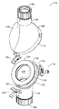
第2の部材14は、第2の脚体24から離れる方向で延在する上面46を有する。上面46は、第2の脚体24の長手方向軸線に対してオフセット角で配向された面内に、またその周りに広く位置する。上面46のオフセット角は基部22のオフセット角と同様であり、この実施形態では約45°である。
The
外壁又はスカート48は、上面46にほぼ垂直な方向で上面46から垂下する。スカート48は、約280°延在する近似的な部分円筒状の部分50と、第2の脚体24から離隔されたスカート48の下端部にある平坦な縁部52とを含む。
The outer wall or
スカート48は、第1の部材12の環状基部22の周りに位置するようにサイズ決めされる。
The
第2の部材14の内部を図3及び5で見ることができる。スカート48は、第2の脚体24付近に位置する二つの内側へと延在する突起54を含む。二つの内側へと延在する突起54は、部分円筒状の部分50の周りで約90°相互から離隔された中心を有し、それぞれスカート48の上端部から約45°を有する。内側へと延在する突起はそれぞれ、部分円筒状の部分50の周りに円周方向で位置合わせされ、各突起54は約45°に沿って延在する。
The interior of the
スカート48はまた、平坦な縁部52の内側に位置する支承部材受入れ部分56を含む。支承部材受入れ部分56は、広くは長方形であり、部分円筒状の部分50によって画成される見かけの円筒に対して接線方向で配向される。支承部材受入れ部分56はその外端部にボルト受入れアパーチャ58を有する。
The
支承部材16は、支承部材受入れ部分56内に位置するようにサイズ及び形状が決められる。支承部材16は、平坦な縁部52に平行な方向で支承部材受入れ部分を通って延在するようにサイズ決めされたボルト60と、ボルト60の遠位端の周りで溝内に位置するように配置された保定クリップ62と、第1の係合部材64と、第2の係合部材66と、分離ばね68とを含む。
The bearing
第1の係合部材64は本体部分70を有し、そこを通って雌ねじ付きアパーチャ72が長手方向で延在する。本体部分70は、支承部材受入れ部分56の約3分の1の長さを有する。雌ねじ付きアパーチャは、ボルト60の雄ねじと係合するように配置される。
The
第1の係合部材64は、本体部分の内側に位置する係合部分74を有する。係合部分74は凹状の形状であり、曲率半径は第1の部材12の環状溝36の内表面40と同様である。係合部分74は、後述するように、環状溝36内に位置するように配置される。
The
第2の係合部材66は第1の係合部材64と同様であり、主な違いは、第2の係合部材の本体部分70を通って延在するアパーチャ72が雌ねじ付きでないことである。
The
ボルト60はその近位端にヘッド76を有する。
説明しやすくするため、支承部材16のアセンブリについては、第2の部材14のみを参照して記載する。支承部材16は、以下のように、第2の部材14内で直接組み立てることができる。第1の係合部材64は支承部材受入れ部分56内に位置決めされ、そのアパーチャ72は支承部材受入れ部分56のアパーチャ58と位置合わせされ、その係合部分74はスカート48の部分円筒状の部分の湾曲にほぼ沿うように配向される。第1の係合部材64は支承部材受入れ部分56の片側に向かって位置する。
For ease of explanation, the assembly of the bearing
第2の係合部材66は、第1の係合部材64に対する鏡像位置で支承部材受入れ部分56内に位置する。第2の係合部材66は支承部材受入れ部分56の他方の側に向かって位置する。
The
分離ばね68は第1及び第2の係合部材64、66の間に位置決めされる。
The
ボルト60は、第1のボルト受入れアパーチャ58、第2の係合部材66のアパーチャ72、分離ばね68、第1の係合部材64のアパーチャ72(そこを通してねじ込まなければならない)、及び第2のボルト受入れアパーチャ58に連続して通される。次に、保定クリップが第2のボルト受入れアパーチャ58の外側でボルト60上に配置されて、ボルト60が第2のボルト受入れアパーチャ58を通って不用意に引き戻されるのを防ぐ。ボルトのヘッド76は第1のボルト受入れアパーチャ58の外側に残る。
The
ばね68の作用は、第2の係合部材66を、第1のボルト受入れアパーチャ58に隣接した支承部材受入れ部分56の側壁に向かって押しやることである。第1の係合部材64の軸線方向位置、またしたがって第1及び第2の係合部材64、66の間の距離は、ボルト60の回転によって変更される。
The action of the
スイベルジョイント10は、第2の部材14及び支承部材16を第1の部材12の周りに配置することによって組み立てられる。最終的な配置は、第2の部材14のスカート48が、内向きの突起54と支承部材16の係合部分74とが環状溝36内に位置する状態で、第1の部材12の上に嵌るような配置である。換言すれば、スカート48は滑り嵌めで第1の部材の基部22の上に嵌って、スイベルジョイント10の外表面を画成する。ボルト60のヘッド76、及び保定クリップ62以外、支承部材16の作動部品はスイベルジョイント10の内側に位置する。特に、係合部分74及び環状溝36である支承面が、外表面の内側に嵌り、水及び埃の進入から全体的に保護されることが理解されるであろう。
The swivel joint 10 is assembled by placing the
この配置は図7の断面に見ることができる。 This arrangement can be seen in the cross section of FIG.
スイベルジョイント10を組み立てるために、最初に、第1及び第2の係合部材64、66並びに分離ばね68を、第1の部材12の環状溝36内でその下面30に配置することが必要である。第1及び第2の係合部材64、66並びに分離ばね68は、手で又は適切な取外し可能なクリップを使用して保持することができる。
In order to assemble the swivel joint 10, it is first necessary to place the first and second engaging
次に、内向きの突起54を溝36内でその上面32に配置し、これらをヒンジとして使用し、次に、スカート48の平坦な縁部52が第1及び第2の係合部材64、66の上に下ろして、第1の部材12の上で第2の部材14を閉じることによって、第2の部材14を第1の部材12の上に位置させることができる。
Next,
第2の部材14が定位置まで下がると、ボルト60を定位置に配置して、第1及び第2の係合部材64、66を第2の部材14に有効に取り付けることができる。
When the
スイベルジョイントがこのように組み立てられると、第1の部材12に対する第2の部材14の回転を、ボルト60の回転によって選択的に許容又は防止することができる。
When the swivel joint is assembled in this way, the rotation of the
ボルト60が締められると、第1の係合部材64は第2の係合部材66へと向けられる。これは、有効曲率半径を低減するように作用し、係合部分74が押しやられて環状溝36と係合される。ボルト60の締付けによってくさび作用が提供され、係合部分74が環状溝36に対して圧締めされ、次に環状溝36が内向きの突起54に押し付けられる。結果として生じる摩擦は、回転を実質的に防止して、スイベルジョイント10を所望の位置で維持するのに十分である。これは図8の断面に見ることができる。
When the
ボルト60が緩められると、逆の作用が生じる。係合部分74は環状溝36との活性の係合から解放され、環状溝36は内向きの突起54に押し付けられなくなる。ここで、オフセット軸を中心にした第1の部材12に対する第2の部材14の回転が許容される。係合部分74及び内向きの突起54は環状溝36内に位置したままであって、第2の部材14が第1の部材12から完全に外れるのを防ぐ。スイベルジョイントは、図1及び8に示されるように第1の脚体18及び第2の脚体24が実質的に平行である、第1の位置と、図9及び10に示されるように第1の脚体18及び第2の脚体24が実質的に垂直である、第2の位置へと回転させることができる。ジョイントは、第1及び第2の位置の間の任意の中間位置へと回転させることができるものと理解されるであろう。第2の部材14のスカート48の回転に応じて、第1の部材12の環状基部22の外周縁を取り囲むままである。このように、スカート48及び基部22を組み合わせて、その周りで回転が起こるほぼ円形のトラックが形成される。
When
ジョイント10の第1の位置は、第1の脚体18及び第2の脚体24が実質的に平行である場合、ジョイント10の主要な配向を表すことが理解されるであろう。図8に見られるように、この配向では、この配向のジョイント10の中心を通るほぼ円筒状の中空の空隙がある。実際に、この空隙は電気ケーブル配線を貫通させる傾向がある。このケーブル配線は空隙を通過するいかなる機械的リンクによっても妨害されないという、本発明の顕著な利点が考慮される。
It will be appreciated that the first position of the joint 10 represents the primary orientation of the joint 10 when the
スイベルジョイント10は、第2の部材14の上面46に取り付けられた係止ピン80によって提供される、補助係止手段を含む。係止ピン80は、係止ピン80が使用の際は第1の部材12の外側リム34にある陥凹部44内まで延在する第1の位置と、係止ピン80が上面46に向かって後退され、第1の部材12とは係合しない第2の位置との間でレバー82を操作することによって可動である。
The swivel joint 10 includes auxiliary locking means provided by a locking
本発明の第2の実施形態について、第1の部材112と、第2の部材114と、三つの支承部材116によって形成される支承装置という三つの主要構成要素を有するスイベルジョイント110が示される、図11〜17を参照して記載する。
For the second embodiment of the present invention, shown is a swivel joint 110 having three main components: a
第1の部材112は、長手方向で配向される第1の脚体118と関連付けられる。第1の脚体118は、圧締め又は溶接などの適切な手段によって柱(照明柱の基部など)に接続するように配置された円筒状スリーブを形成する、柱受入れアパーチャ120で終端する。
The
第2の部材114は、長手方向で配向される第2の脚体124と関連付けられる。第2の脚体124は、圧締め又は溶接などの適切な手段によって柱(照明柱の上側部分など)に接続するように配置された円筒状スリーブを形成する、柱受入れアパーチャ126で終端する。
The
配置は、スイベルジョイント110が図11に示されるような第1の位置にあるとき、第1の脚体118及び第2の脚体124の両方が垂直であることができ、共通の長手方向軸線に沿って位置合わせされるような配置である。
The arrangement is such that when the swivel joint 110 is in the first position as shown in FIG. 11, both the
第1の部材112は、先細の接続部分128によって第1の脚体118に接続される環状基部122を有する。
The
環状基部122は、第1の脚体118の長手方向軸線に対してオフセット角で配向される面を画成する。オフセット角は鋭角である。図示される実施形態では、オフセット角は45°である。
The
環状基部122は、直径が第1の脚体118のほぼ二倍の円形である。環状基部122は、下面130が第1の脚体118によって画成される見かけの円筒に近く、上面132が見かけの円筒から離隔されるようにして位置決めされる。
The
第1の部材112は、基部122に平行であってそこから離隔された環状の外側リム134を有する。外側リム134は、直径が基部122の直径に類似した円形である。基部122及び外側リム134は、長手方向軸線に対してオフセット角で配向される、共通のオフセット軸に沿って位置合わせされる。
The
配置は、外側リム134の上面が第1の脚体118によって画成される見かけの円筒に近いような配置である。
The arrangement is such that the upper surface of the
環状溝136は基部122と外側リム134との間に位置する。環状溝136は「底部が平坦なV」字形の断面である。換言すれば、環状溝136は、内側へと先細になった下側の円錐台形表面138と、円筒状の内表面140と、外側へと先細状になった上側の円錐台形表面142とによって形成される。下側の円錐台形表面138は基部122と内表面140との間を延在し、上側の円錐台形表面142は内表面140と外側リム134との間を延在する。円筒状の内表面140はオフセット軸に沿って位置合わせされ、直径は外側リム134の約90%である。
The
第2の部材114は、第2の脚体124から離れる方向で延在する上面146を有する。上面146は、第2の脚体124の長手方向軸線に対してオフセット角で配向された面内に、またその周りに広く位置する。上面146のオフセット角は基部122と同様であり、この実施形態では約45°である。
The
外壁又はスカート148は、上面146にほぼ垂直な方向で上面146から垂下する。スカート148はほぼ円筒形状である。
The outer wall or
スカート148は、第1の部材112の環状基部122の周りに位置するようにサイズ決めされる。
The
第2の部材114の内部を図14で見ることができる。スカート114は、三つのボルト受入れアパーチャ158がスカート148の円周部の周りに均等な距離で離隔された、ほぼ円筒状の内表面を有する。ボルト受入れアパーチャ158は皿穴状である。
The interior of the
各支承部材116は、環状溝136内に位置するようにサイズ及び形状が決められる。各支承部材116は、支承部材116を通って延在するようにサイズ決めされたボルト160と、雌ねじ付きアパーチャ172が中を通って延在する本体部分170と、雌ねじ付きアパーチャ172から離隔された係合部分174と、雌ねじ付きアパーチャ172に隣接した隆起部分178とを含む。係合部分174及び隆起部分178は本体部分170の対向面上にある。雌ねじ付きアパーチャ172は、ボルト160の雄ねじと係合するように配置される。
Each
各ボルト160は、ボルト受入れアパーチャ158の外側部分内に位置するように配置されたヘッド176を有する。
Each
スイベルジョイント110は、第2の部材114及び支承部材116を第1の部材112の周りに配置することによって組み立てられる。最終的な配置は、第2の部材114のスカート148が、支承部材116の係合部分174が環状溝136内に位置する状態で、第1の部材112の上に嵌るような配置である。
The swivel joint 110 is assembled by placing the
この配置は図15の断面に見ることができる。 This arrangement can be seen in the cross section of FIG.
スイベルジョイント110を組み立てるために、最初に、三つの支承部材116の本体部分170を、第1の部材112の環状溝136内の適切な位置に配置することが必要である。本体部分170は、手で又は適切な取外し可能なクリップを使用して保持することができる。
In order to assemble the swivel joint 110, it is first necessary to place the
次に、第2の部材114を第1の部材112の上に配置することができる。
Next, the
第2の部材114が定位置まで下がると、ボルト160を定位置に配置して、支承部材116の本体部分170を第2の部材114に有効に取り付けることができる。
When the
スイベルジョイントがこのように組み立てられると、第1の部材112に対する第2の部材114の回転を、ボルト160の回転によって選択的に許容又は防止することができる。
When the swivel joint is assembled in this way, rotation of the
各ボルト160を第1の方向で回すと、アパーチャ172に隣接した本体部分170がボルト受入れアパーチャ158に向かって押しやられる。隆起部分178は、スカート148の内部に対するピボットとして作用して、係合部分174を押しやって環状溝136と係合させる。ボルト160をこの方向で更に締め付けると、くさび作用が提供され、係合部分174が環状溝136に対して圧締めされる。結果として得られる摩擦は、スイベルジョイント110を所望の位置へと係止して、回転を防ぐのに十分である。これは図16に示される。
As each
ボルト160を他方の方向で回すと、逆の効果が起こる。係合部分174は、環状溝136との活性の係合から解放され、アパーチャ172に隣接した本体部分170が内側に動くにつれて外側に引っ張られる。ここで、オフセット軸を中心にした第1の部材112に対する第2の部材114の回転が許容される。本体部分170は環状溝136内に位置したままであって、第2の部材114が第1の部材112から完全に外れるのを防ぐ。これは図17に示される。
When the
一つの変形(図示なし)では、この実施形態は、係合部分を環状溝136に向かって押しやるように作用する、支承部材116の周りを包囲するばねを含む。このばねは係合部分174を締め付けるのを支援する。
In one variation (not shown), this embodiment includes a spring that surrounds the bearing
図面には示されないが、第1の実施形態に示されるものに類似した補助係止手段を、第2の実施形態に容易に追加できることが考えられる。 Although not shown in the drawings, it is conceivable that auxiliary locking means similar to those shown in the first embodiment can be easily added to the second embodiment.
本発明の第3の実施形態について、第1の部材212と、第2の部材214と、支承部材216という三つの主要構成要素を有するスイベルジョイント210が示される、図18〜25を参照して記載する。
With reference to FIGS. 18-25, a swivel joint 210 having three main components, a
第1の部材212は、長手方向で配向される第1の脚体218と関連付けられる。第1の脚体218は、圧締め又は溶接などの適切な手段によって柱(照明柱の基部など)に接続するように配置された円筒状スリーブを形成する、柱受入れアパーチャ220で終端する。
The
第2の部材214は、長手方向で配向される第2の脚体224と関連付けられる。第2の脚体224は、圧締め又は溶接などの適切な手段によって柱(照明柱の上側部分など)に接続するように配置された円筒状スリーブを形成する、柱受入れアパーチャ226で終端する。
The
配置は、スイベルジョイント210が図18に示されるような第1の位置にあるとき、第1の脚体218及び第2の脚体224の両方が垂直であることができ、共通の長手方向軸線に沿って位置合わせされるような配置である。
The arrangement is such that when the swivel joint 210 is in the first position as shown in FIG. 18, both the
第1の部材212は全体的に中空であり、下面228と、全体的に円筒状の側壁230と、上側肩部222と、上向きに延在する円筒状の突起234とを有する。第1の部材212は、全体として下面228及び側壁230によって画成される中空本体部分を有する。
The
側壁230はその内径の約10%の厚さを有する。図面に示される実施形態では、側壁は175mmの外径及び140mmの内径を有する。側壁230は上面228及び上側肩部222を分離する。上側肩部222は多数の「カットアウト」部分又は陥凹部244を含む。
The
上側肩部222は側壁230の内側に延在し、下面228に対向する。上側肩部222はほぼ環状であり、内径は側壁230の外径の約70%に等しい。図示される実施形態では、上側肩部は約125mmの内径を有する。
The
上側肩部222は、第1の部材212の外側にある外面236と、第1の部材212の内側であって下面228に面する内面238とを有する。内面238はほぼ環状である。図示される好ましい実施形態では、内面238は円錐台形であり、円錐角が約135°であって、下面228から内面238までの距離が側壁230から離れると増加するように配向される。
The
内面238は、中空本体部分に向かって配向される支承面である。
The
円筒状の突起234は、上側肩部222の外面236から上向きに延在する。円筒状の突起234は、側壁230の外径の約85%である外径を有する。図示される実施形態では、円筒状の突起234は約147mmに等しい外径を有する。
The
円筒状の突起は円錐台形の内部形状を有してもよく、内径は上側肩部222の内縁部から円筒状の突起の上縁部まで増加する。この形状の円錐角は約45°である。
The cylindrical protrusion may have a frustoconical internal shape, and the inner diameter increases from the inner edge of the
第2の部材214はほぼ円錐台形の上側表面246とほぼ円筒状のスカート248とを有する。スカート248は、上側表面246の周囲から下向きに垂下し、第1の部材212の円筒状の突起234の外径に等しい内径を有する。したがって、第2の部材214のスカート248は円形の陥凹部を画成し、その中に第1の部材212の円筒状の突起234が位置することができる。
The
第2の部材214は、上側表面246の周囲付近に120°の間隔で離隔された、三つのボルト受入れアパーチャ258を含む。ボルト受入れアパーチャ258は、短い距離だけスカート248の径方向内側に位置する。ボルト受入れアパーチャ258は上側表面246に対して垂直であり、即ち、第2の脚体224の長手方向に対して約22.5°の角度であり、スカート248からボルト受入れアパーチャ258それぞれまでの距離が上側表面246から離れると増加するようにして、第2の部材214の中心軸に向かって配向される。
The
支承部材216はほぼ円錐台形であり、円錐角は135°である。また、ほぼ環状の形状であり、外径が第1の部材212の側壁230の内径に類似し、内径はその外径の約3分の1である。図面に示される支承部材216は約12mmの高さを有する。第1の部材212の中空本体部分内に位置するようにサイズ決めされ、支承部材216の外側リムが第1の部材212の肩部222の下に位置する。
The bearing
支承部材216は円形の外周縁を有さない。その代わりに、その周囲は、支承部材216を第1の部材212の中空本体部分に挿入できるようにして形作られる。
The
支承部材216は、支承部材216の周囲付近に120°の間隔で離隔された、三つの雌ねじ付きのボルト受入れアパーチャ256を有する。ボルト受入れアパーチャ256は支承部材216の上側表面に対して垂直であり、即ち、支承部材216の中心軸に対して22.5°傾斜している。ボルト受入れアパーチャ256の径方向位置は、後述するように、第2の部材214のボルト受入れアパーチャ258と整合される。
The bearing
スイベルジョイント210は、支承部材216を第1の部材212の中空本体部分内へと動かして、支承部材216の円錐状の上側表面の外側リムを第1の部材212の肩部222の内面238に当接させることによって組み立てられる。その結果、第2の部材214は第1の部材212の上に位置することができ、第1の部材212の円筒状の突起234は、第2の部材214のスカート248によって画成される円形の陥凹部内に位置する。第1の部材212の円筒状の突起234の上縁部は、接続環体に沿った第2の部材214の円形の陥凹部と接触している。
The swivel joint 210 moves the bearing
組立てのこの段階の間、第2の部材214は円筒状の突起234を中心にして自由に回転できる。したがって、第2の部材214のボルト受入れアパーチャ258が支承部材216のボルト受入れアパーチャ256と整列するまで回転させることができる。これらのボルト受入れアパーチャは全て、スイベルジョイント210の中心軸に対して22.5°で位置合わせされ、それらそれぞれの径方向位置によって、第2の部材214を適正位置へと回転させたときにボルト受入れアパーチャ256、258を軸方向で整列させることが可能になることが理解されるであろう。
During this stage of assembly, the
ボルト260の形態の調節可能な接続手段を、ボルト受入れアパーチャ258に挿入し、ボルト受入れアパーチャ256のねじ山に受け入れることができる。この配置は図24の断面に示される。
An adjustable connection means in the form of a
ボルト260の締付けによって、環状の外側支承面として作用する支承部材216の外側リムが、第1の部材212の肩部222の内面238を上向きに支える。
By tightening the
したがって、スイベルジョイント210は、ボルト260が締まっている第1の構成と、ボルト260が緩んでいる第2の構成との間で可動である。
Accordingly, swivel joint 210 is movable between a first configuration in which
第1の構成では、支承部材216の支承面は第1の部材212の支承面に接して堅く保持される。結果として得られる摩擦によって、支承部材216及び第1の部材212の相対回転が防止され、したがって第1の部材212及び第2の部材214の相対回転が防止される。
In the first configuration, the bearing surface of the bearing
第2の構成では、肩部222に対する支承部材216の作用によって、第1の部材212が第2の部材214から分離するのが防止される。支承部材216と肩部222との間に圧力が、また著しい摩擦がないことによって、支承部材216及びしたがって第2の部材214が第1の部材212に対して自由に回転できる。したがって、スイベルジョイントは、PCT公報WO0125687のSwivelpoleジョイントと同様の方法で作用することができる。
In the second configuration, the action of the
第1の部材212の円筒状の突起234と第2の部材214の円形の陥凹部との間の相互作用は、そこを中心にして回転が起こり得る「トラック」を提供するだけでなく、水が第1の部材212の中空本体部分に進入するのを防ぐ、水を妨げるリングとしても作用することが理解されるであろう。ボルト260は全て、この水を妨げるリングの径方向内側に位置し、したがって、水及び他の汚染物質から比較的自由に保たれる。
The interaction between the
スイベルジョイント210の中心軸に対して22.5°というボルト260の角度、及び角度を付けた円錐台形表面の調和した使用は、ボルト260が水を妨げるリング内に保たれた状態でボルト260を中心軸からできるだけ離して位置させるのを支援する。これは、ボルト260の強制的分布及び動作の容易さの両方を支援する。しかしながら、この角度付けは本発明の動作にとって必須ではなく、22.5°の角度が製造のためには最も簡単であると考えられるが、決してボルト260を傾斜させることができる唯一の有用な角度ではないことが注目される。同様に、ボルト260はそれに対してほぼ垂直な表面を通して作用するが、これは本発明の動作にとって必須ではない。
The coordinated use of the
スイベルジョイント210は、ボルト260を締め付けるか又は緩める間、スイベルジョイント210を所望の回転位置で固定できるようにする、補助係止手段を含む。この補助係止手段は、第2の部材214の整列された補助アパーチャ284内の補助係止ピン280と第1の部材212の陥凹部244とを使用することによって形成される。
The swivel joint 210 includes auxiliary locking means that allow the swivel joint 210 to be locked in the desired rotational position while tightening or loosening the
第2の部材214の補助アパーチャ284は、第2の部材214の周囲付近に位置し、即ち、スカート248内、したがって水を妨げるリングの外側に位置する。
The
第1の部材212の陥凹部244は、第1の部材212の側壁230の外周縁から内側に延在する、軸方向で整列された陥凹部として形成される。
The
図示される実施形態では、補助係止ピン280はU字形であり、ピン280の一つのアームが、第2の部材214の補助アパーチャ284に隣接したピン保持アパーチャ286内で固定される。
In the illustrated embodiment, the
第2の部材214が第1の部材212に対して所望の回転位置にあるとき、第2の部材214の少なくとも一つの補助アパーチャ284は、第1の部材212の陥凹部244と位置合わせされる。補助係止ピン280は、位置合わせされた補助アパーチャ284及び陥凹部244内に位置して、スイベルジョイント210をこの所望の位置で維持することができる。
When the
補助アパーチャ284及び陥凹部244は自由に排水するように設計されるので、水又は他の汚染物質があっても容易に排出させることが可能であることが理解される。
It will be appreciated that the
当業者には明白であろう修正及び変形は、本発明の範囲内にあるものとする。 Modifications and variations that will be apparent to those skilled in the art are intended to be within the scope of the present invention.
Claims (7)
前記第1の部材が第1の脚体と関連付けられ、前記第1の脚体が長手方向を有し、前記第1の部材が前記第1の脚体の前記長手方向に対して鋭角で配向された環状基部を有し、前記基部が外周縁を有し、
前記第2の部材が第2の脚体と関連付けられ、前記第2の脚体が長手方向を有し、前記第2の部材が、前記第1の部材の前記環状基部の周りに位置して前記スイベルジョイントの外表面を画成するように配置された外壁を含み、
前記第1の部材が、前記スイベルジョイントの前記外表面の内側に位置する支承面を有し、
前記支承部材が調節可能な接続手段によって前記第2の部材に接続され、
前記支承部材が前記第2の部材の前記外壁内に位置し、前記支承部材の前記支承面が前記第1の部材の前記支承面に対向し、
前記調節可能な接続手段によって、
前記支承部材の前記支承面及び前記第1の部材の前記支承面が摩擦係合して、前記第2の部材に対する前記第1の部材の回転移動を制限する第1の構成と、
前記第1の部材に対する前記第2の部材の回転が許容される第2の構成との間で、前記支承部材及び前記第2の部材の相対移動が可能になる、スイベルジョイント。 A swivel joint including a first member, a second member, and at least one support member,
The first member is associated with a first leg, the first leg has a longitudinal direction, and the first member is oriented at an acute angle with respect to the longitudinal direction of the first leg. An annular base portion, the base portion has an outer peripheral edge,
The second member is associated with a second leg, the second leg has a longitudinal direction, and the second member is positioned around the annular base of the first member. Including an outer wall arranged to define an outer surface of the swivel joint;
The first member has a bearing surface located inside the outer surface of the swivel joint;
The bearing member is connected to the second member by an adjustable connecting means;
The support member is located in the outer wall of the second member, the support surface of the support member is opposed to the support surface of the first member;
By said adjustable connecting means,
A first configuration in which the bearing surface of the bearing member and the bearing surface of the first member are frictionally engaged to limit rotational movement of the first member relative to the second member;
A swivel joint that enables relative movement of the support member and the second member with respect to a second configuration in which rotation of the second member with respect to the first member is allowed.
前記第1の部材が第1の脚体と関連付けられ、前記第1の脚体が長手方向を有し、前記第1の部材が前記第1の脚体の前記長手方向に対して鋭角で配向された環状基部を有し、前記基部が外周縁を有し、
前記第2の部材が第2の脚体と関連付けられ、前記第2の脚体が長手方向を有し、前記第2の部材が、前記第1の部材の前記環状基部の周りに位置して前記スイベルジョイントの外表面を画成するように配置された外壁を含み、
前記第2の部材が、前記スイベルジョイントの前記外表面の内側に位置する支承面を有し、
前記支承部材が調節可能な接続手段によって前記第1の部材に接続され、
前記支承部材が前記第2の部材の前記外壁内に位置し、前記支承部材の前記支承面が前記第2の部材の前記支承面に対向し、
前記調節可能な接続手段によって、
前記支承部材の前記支承面及び前記第2の部材の前記支承面が摩擦係合して、前記第2の部材に対する前記第1の部材の回転移動を制限する第1の構成と、
前記第1の部材に対する前記第2の部材の回転が許容される第2の構成との間で、前記支承部材及び前記第1の部材の相対移動が可能になる、スイベルジョイント。 A swivel joint including a first member, a second member, and at least one support member,
The first member is associated with a first leg, the first leg has a longitudinal direction, and the first member is oriented at an acute angle with respect to the longitudinal direction of the first leg. An annular base portion, the base portion has an outer peripheral edge,
The second member is associated with a second leg, the second leg has a longitudinal direction, and the second member is positioned around the annular base of the first member. Including an outer wall arranged to define an outer surface of the swivel joint;
The second member has a bearing surface located inside the outer surface of the swivel joint;
The support member is connected to the first member by an adjustable connection means;
The bearing member is located in the outer wall of the second member, the bearing surface of the bearing member is opposed to the bearing surface of the second member;
By said adjustable connecting means,
A first configuration in which the bearing surface of the bearing member and the bearing surface of the second member are frictionally engaged to limit the rotational movement of the first member relative to the second member;
A swivel joint that enables relative movement of the support member and the first member with a second configuration in which rotation of the second member with respect to the first member is allowed.
前記第1の部材が第1の脚体と関連付けられ、前記第1の脚体が長手方向を有し、前記第1の部材が基部を有し、前記基部が外周縁を有し、前記外周縁が面内に位置し、前記面が動作軸に垂直であり、前記動作軸がオフセット角で前記第1の脚体の前記長手方向軸線に対して角度を付けられ、
前記第2の部材が第2の脚体と関連付けられ、前記第2の脚体が長手方向を有し、前記第2の部材が、前記第1の部材の前記環状基部の周りに位置して前記スイベルジョイントの外表面を画成するように配置された外壁を含み、
前記第1の部材が、前記スイベルジョイントの前記外表面の内側に位置する支承面を有し、
前記支承部材が調節可能な接続手段によって前記第2の部材に接続され、
前記支承部材が前記第2の部材の前記外壁内に位置し、前記支承部材の前記支承面が前記第1の部材の前記支承面に対向し、
前記調節可能な接続手段によって、
前記支承部材の前記支承面及び前記第1の部材の前記支承面が摩擦係合して、前記第2の部材に対する前記第1の部材の回転移動を制限する第1の構成と、
前記第1の部材に対する前記第2の部材の回転が許容される第2の構成との間で、前記支承部材及び前記第1の部材の相対移動が可能になる、スイベルジョイント。 A swivel joint including a first member, a second member, and at least one support member,
The first member is associated with a first leg, the first leg has a longitudinal direction, the first member has a base, the base has an outer peripheral edge, and the outer A peripheral edge is located in the plane, the plane is perpendicular to the motion axis, and the motion axis is angled with respect to the longitudinal axis of the first leg at an offset angle;
The second member is associated with a second leg, the second leg has a longitudinal direction, and the second member is positioned around the annular base of the first member. Including an outer wall arranged to define an outer surface of the swivel joint;
The first member has a bearing surface located inside the outer surface of the swivel joint;
The bearing member is connected to the second member by an adjustable connecting means;
The support member is located in the outer wall of the second member, the support surface of the support member is opposed to the support surface of the first member;
By said adjustable connecting means,
A first configuration in which the bearing surface of the bearing member and the bearing surface of the first member are frictionally engaged to limit rotational movement of the first member relative to the second member;
A swivel joint that enables relative movement of the support member and the first member with a second configuration in which rotation of the second member with respect to the first member is allowed.
前記第1の部材が第1の脚体と関連付けられ、前記第1の脚体が長手方向を有し、前記第1の部材が中空本体部分を有し、前記第1の部材が前記第1の脚体の前記長手方向に対して鋭角で配向された支承面を有し、前記支承面が前記中空本体部分に面し、
前記第2の部材が第2の脚体と関連付けられ、前記第2の脚体が長手方向を有し、
前記支承部材が調節可能な接続手段によって前記第2の部材に接続され、前記支承部材が前記第1の脚体の前記長手方向に対して鋭角で配向された支承面を有し、
前記支承部材が前記第1の部材の前記中空本体部分内に位置し、前記支承部材の前記支承面が前記第1の部材の前記支承面に対向し、
前記調節可能な接続手段によって、
前記支承部材の前記支承面及び前記第1の部材の前記支承面が摩擦係合して、前記第2の部材に対する前記第1の部材の回転移動を制限する第1の構成と、
前記第1の部材に対する前記第2の部材の回転が許容される第2の構成との間で、前記支承部材及び前記第2の部材の相対移動が可能になる、スイベルジョイント。 A swivel joint including a first member, a second member, and a support member,
The first member is associated with a first leg, the first leg has a longitudinal direction, the first member has a hollow body portion, and the first member is the first leg. A bearing surface oriented at an acute angle with respect to the longitudinal direction of the leg of the leg, the bearing surface facing the hollow body portion;
The second member is associated with a second leg, the second leg has a longitudinal direction;
The bearing member is connected to the second member by an adjustable connection means, the bearing member having a bearing surface oriented at an acute angle with respect to the longitudinal direction of the first leg;
The bearing member is located in the hollow body portion of the first member, and the bearing surface of the bearing member faces the bearing surface of the first member;
By said adjustable connecting means,
A first configuration in which the bearing surface of the bearing member and the bearing surface of the first member are frictionally engaged to limit rotational movement of the first member relative to the second member;
A swivel joint that enables relative movement of the support member and the second member with respect to a second configuration in which rotation of the second member with respect to the first member is allowed.
前記第1の部材が長手方向で延在する第1の脚体と関連付けられ、前記第1の脚体が長手方向を有し、前記第1の部材が中空本体部分を有し、前記第1の部材が前記第1の脚体の前記長手方向に対して鋭角で配向された支承面を有し、前記支承面が前記第1の脚体に面し、
前記第2の部材が長手方向で延在する第2の脚体と関連付けられ、前記第2の脚体が長手方向を有し、
前記第1の部材及び前記第2の部材が接続環体に沿って交わるように配置され、
前記支承部材が調節可能な接続手段によって前記第2の部材に接続され、前記支承部材が前記第1の脚体の前記長手方向に対して鋭角で配向された支承面を有し、
前記支承部材が前記接続環体の内部に位置し、前記支承部材の前記支承面が前記第1の部材の前記支承面に対向し、
前記調節可能な接続手段によって、
前記支承部材の前記支承面及び前記第1の部材の前記支承面が摩擦係合して、前記第1の部材及び前記第2の部材の相対移動を制限する第1の構成と、
前記第1の部材に対する前記第2の部材の回転が許容される第2の構成との間で、前記支承部材及び前記第2の部材の相対移動が可能になる、スイベルジョイント。 A swivel joint including a first member, a second member, and a support member,
The first member is associated with a first leg that extends in a longitudinal direction, the first leg has a longitudinal direction, the first member has a hollow body portion, and The member has a bearing surface oriented at an acute angle with respect to the longitudinal direction of the first leg, and the bearing surface faces the first leg,
The second member is associated with a second leg extending in a longitudinal direction, the second leg having a longitudinal direction;
The first member and the second member are arranged so as to cross along a connection ring,
The bearing member is connected to the second member by an adjustable connection means, the bearing member having a bearing surface oriented at an acute angle with respect to the longitudinal direction of the first leg;
The support member is located inside the connection ring, and the support surface of the support member faces the support surface of the first member;
By said adjustable connecting means,
A first configuration in which the bearing surface of the bearing member and the bearing surface of the first member are frictionally engaged to limit relative movement of the first member and the second member;
A swivel joint that enables relative movement of the support member and the second member with respect to a second configuration in which rotation of the second member with respect to the first member is allowed.
前記第1の部材が第1の脚体と関連付けられ、前記第1の脚体が長手方向を有し、前記第1の部材が中空本体部分を有し、前記第1の部材が前記第1の脚体の前記長手方向に対して鋭角で配向された支承面を有し、前記支承面が前記中空本体部分に面し、
前記第2の部材が第2の脚体と関連付けられ、前記第2の脚体が長手方向を有し、
前記支承部材が調節可能な接続手段によって前記第2の部材に接続され、前記支承部材が前記第1の脚体の前記長手方向に対して鋭角で配向された支承面を有し、
前記支承部材が前記第1の部材の前記中空本体部分の内部に位置し、前記支承部材の前記支承面が前記第1の部材の前記支承面に対向し、
前記調節可能な接続手段によって、
前記支承部材の前記支承面及び前記第1の部材の前記支承面が摩擦係合して、前記第2の部材に対する前記第1の部材の回転移動を制限する第1の構成と、
前記第1の部材に対する前記第2の部材の回転が許容される第2の構成との間で、前記支承部材及び前記第2の部材の相対移動が可能になる、スイベルジョイント。 A swivel joint including a first member, a second member, and a support member,
The first member is associated with a first leg, the first leg has a longitudinal direction, the first member has a hollow body portion, and the first member is the first leg. A bearing surface oriented at an acute angle with respect to the longitudinal direction of the leg of the leg, the bearing surface facing the hollow body portion;
The second member is associated with a second leg, the second leg has a longitudinal direction;
The bearing member is connected to the second member by an adjustable connection means, the bearing member having a bearing surface oriented at an acute angle with respect to the longitudinal direction of the first leg;
The bearing member is located inside the hollow body portion of the first member, the bearing surface of the bearing member is opposed to the bearing surface of the first member;
By said adjustable connecting means,
A first configuration in which the bearing surface of the bearing member and the bearing surface of the first member are frictionally engaged to limit rotational movement of the first member relative to the second member;
A swivel joint that enables relative movement of the support member and the second member with respect to a second configuration in which rotation of the second member with respect to the first member is allowed.
前記第1の部材が長手方向で延在する第1の脚体と関連付けられ、前記第1の脚体が長手方向を有し、前記第1の部材が中空本体部分を有し、前記第1の部材が前記第1の脚体の前記長手方向に対して鋭角で配向された支承面を有し、前記支承面が前記第1の脚体に面し、
前記第2の部材が長手方向で延在する第2の脚体と関連付けられ、前記第2の脚体が長手方向を有し、
前記第1の部材及び前記第2の部材が接続環体に沿って交わるように配置され、
前記支承部材が調節可能な接続手段によって前記第2の部材に接続され、前記支承部材が前記第1の脚体の前記長手方向に対して鋭角で配向された支承面を有し、
前記支承部材が前記接続環体の内部に位置し、前記支承部材の前記支承面が前記第1の部材の前記支承面に対向し、
前記調節可能な接続手段によって、
前記支承部材の前記支承面及び前記第1の部材の前記支承面が摩擦係合して、前記第2の部材に対する前記第1の部材の回転移動を制限する第1の構成と、
前記第1の部材に対する前記第2の部材の回転が許容される第2の構成との間で、前記支承部材及び前記第2の部材の相対移動が可能になる、スイベルジョイント。
A swivel joint including a first member, a second member, and a support member,
The first member is associated with a first leg that extends in a longitudinal direction, the first leg has a longitudinal direction, the first member has a hollow body portion, and The member has a bearing surface oriented at an acute angle with respect to the longitudinal direction of the first leg, and the bearing surface faces the first leg,
The second member is associated with a second leg extending in a longitudinal direction, the second leg having a longitudinal direction;
The first member and the second member are arranged so as to cross along a connection ring,
The bearing member is connected to the second member by an adjustable connection means, the bearing member having a bearing surface oriented at an acute angle with respect to the longitudinal direction of the first leg;
The support member is located inside the connection ring, and the support surface of the support member faces the support surface of the first member;
By said adjustable connecting means,
A first configuration in which the bearing surface of the bearing member and the bearing surface of the first member are frictionally engaged to limit rotational movement of the first member relative to the second member;
A swivel joint that enables relative movement of the support member and the second member with respect to a second configuration in which rotation of the second member with respect to the first member is allowed.
Applications Claiming Priority (3)
| Application Number | Priority Date | Filing Date | Title |
|---|---|---|---|
| AU2013904795A AU2013904795A0 (en) | 2013-12-10 | A Swivelling joint | |
| AU2013904795 | 2013-12-10 | ||
| PCT/AU2014/050412 WO2015085366A1 (en) | 2013-12-10 | 2014-12-10 | A swivelling joint |
Publications (3)
| Publication Number | Publication Date |
|---|---|
| JP2017515012A JP2017515012A (en) | 2017-06-08 |
| JP2017515012A5 JP2017515012A5 (en) | 2018-01-18 |
| JP6442509B2 true JP6442509B2 (en) | 2018-12-19 |
Family
ID=53370374
Family Applications (1)
| Application Number | Title | Priority Date | Filing Date |
|---|---|---|---|
| JP2016539214A Active JP6442509B2 (en) | 2013-12-10 | 2014-12-10 | Swivel joint |
Country Status (18)
| Country | Link |
|---|---|
| US (1) | US9945143B2 (en) |
| EP (1) | EP3094921B1 (en) |
| JP (1) | JP6442509B2 (en) |
| KR (1) | KR102263682B1 (en) |
| CN (1) | CN105899872B (en) |
| AU (5) | AU2014361747B2 (en) |
| CA (1) | CA2933051C (en) |
| CL (1) | CL2016001439A1 (en) |
| EA (1) | EA033182B1 (en) |
| ES (1) | ES2830356T3 (en) |
| HU (1) | HUE052125T2 (en) |
| IL (1) | IL246058A0 (en) |
| MX (1) | MX2016007647A (en) |
| MY (1) | MY178402A (en) |
| PL (1) | PL3094921T3 (en) |
| PT (1) | PT3094921T (en) |
| SA (1) | SA516371294B1 (en) |
| WO (1) | WO2015085366A1 (en) |
Families Citing this family (12)
| Publication number | Priority date | Publication date | Assignee | Title |
|---|---|---|---|---|
| PL3389374T3 (en) * | 2015-12-15 | 2023-08-14 | Evolution International Holdings Pty Ltd | Rotatable fishing rod holder |
| WO2018042348A1 (en) | 2016-08-31 | 2018-03-08 | Apollo Energy Services Corp | Drilling rig with attached lighting system and method |
| US10473282B2 (en) | 2018-03-15 | 2019-11-12 | JCA Rentals, LLC | Elevated structure-mounted lighting system |
| US10976016B2 (en) | 2018-03-15 | 2021-04-13 | C&M Oilfield Rentals, Llc | Elevated structure-mounted lighting system |
| USD829599S1 (en) * | 2018-03-24 | 2018-10-02 | John Reed Sanderson, Jr. | Apparatus for mounting a flagstaff and flag |
| USD829598S1 (en) * | 2018-03-24 | 2018-10-02 | John Reed Sanderson, Jr. | Apparatus for mounting a flagstaff and flag |
| CA3137043A1 (en) * | 2019-04-17 | 2020-10-22 | Troy Reece Culley | Swing arrangement for a pole |
| KR102144466B1 (en) * | 2020-02-03 | 2020-08-13 | 신화산업전기 주식회사 | Posts for explosion proof lamp |
| DE202020104394U1 (en) * | 2020-07-29 | 2021-11-02 | Neoperl Gmbh | Sanitary interface, sanitary fitting, construction kit for producing a sanitary interface and using a sanitary interface |
| CN112664915B (en) * | 2020-12-29 | 2023-10-27 | 安徽将煜电子科技有限公司 | Sleeve for lamp post and preparation method thereof |
| KR102361709B1 (en) * | 2021-06-08 | 2022-02-14 | 권도근 | Explosion-proof safety streetlight |
| KR102516179B1 (en) | 2022-07-26 | 2023-03-30 | 권도근 | Swivel support and installation method of safety post using this swivel support |
Family Cites Families (13)
| Publication number | Priority date | Publication date | Assignee | Title |
|---|---|---|---|---|
| GB774324A (en) * | 1954-06-26 | 1957-05-08 | Svend Middelboe | Swivelling joint |
| US3366788A (en) * | 1965-07-30 | 1968-01-30 | Imagineers Inc | Seal swivel joint for vehicle warning light |
| FR2662781B1 (en) | 1990-06-01 | 1994-05-27 | Decaux Jc | LIGHTING APPARATUS AND PUBLIC HIGHWAY LIGHTING INSTALLATION COMPRISING SEVERAL LIGHTING APPARATUSES. |
| US5016154A (en) * | 1990-09-04 | 1991-05-14 | Leeyeh Chuing Hui | Connection structure for the supporting rod of a floor lamp |
| JPH07151288A (en) * | 1993-11-29 | 1995-06-13 | Sekisui Chem Co Ltd | Universal coupling |
| AUPQ325199A0 (en) * | 1999-10-05 | 1999-10-28 | Pannekoek, Robert John | An elongate member |
| US6902200B1 (en) * | 2000-03-28 | 2005-06-07 | Joshua Beadle | Contaminant-resistant pivot joint for outdoor lighting fixture |
| US6957332B1 (en) | 2000-03-31 | 2005-10-18 | Intel Corporation | Managing a secure platform using a hierarchical executive architecture in isolated execution mode |
| CN2445196Y (en) * | 2000-07-10 | 2001-08-29 | 天津赛德电气设备有限公司 | Bandable lamp rod |
| US7690822B2 (en) * | 2008-01-29 | 2010-04-06 | Thomas & Betts International, Inc. | Swivel joint for lighting fixture |
| WO2010085859A1 (en) | 2009-01-30 | 2010-08-05 | Safe Swivel Patent Co Pty Ltd | Switch for a pole having moveable portions |
| US20150050069A1 (en) * | 2012-04-12 | 2015-02-19 | Swivelpole Patent Pty Ltd | Swivelling joint |
| US20140360754A1 (en) * | 2013-06-07 | 2014-12-11 | Swivelpole Patent Pty Ltd. | Environmentally Robust Pivot Joint Adaptor |
-
2014
- 2014-12-10 KR KR1020167018365A patent/KR102263682B1/en active IP Right Grant
- 2014-12-10 AU AU2014361747A patent/AU2014361747B2/en active Active
- 2014-12-10 HU HUE14868887A patent/HUE052125T2/en unknown
- 2014-12-10 PL PL14868887T patent/PL3094921T3/en unknown
- 2014-12-10 ES ES14868887T patent/ES2830356T3/en active Active
- 2014-12-10 PT PT148688872T patent/PT3094921T/en unknown
- 2014-12-10 US US15/102,563 patent/US9945143B2/en active Active
- 2014-12-10 CA CA2933051A patent/CA2933051C/en active Active
- 2014-12-10 EA EA201600452A patent/EA033182B1/en unknown
- 2014-12-10 EP EP14868887.2A patent/EP3094921B1/en active Active
- 2014-12-10 MX MX2016007647A patent/MX2016007647A/en unknown
- 2014-12-10 MY MYPI2016702101A patent/MY178402A/en unknown
- 2014-12-10 WO PCT/AU2014/050412 patent/WO2015085366A1/en active Application Filing
- 2014-12-10 JP JP2016539214A patent/JP6442509B2/en active Active
- 2014-12-10 CN CN201480066667.XA patent/CN105899872B/en active Active
-
2016
- 2016-06-06 IL IL246058A patent/IL246058A0/en unknown
- 2016-06-10 CL CL2016001439A patent/CL2016001439A1/en unknown
- 2016-06-10 SA SA516371294A patent/SA516371294B1/en unknown
-
2019
- 2019-07-16 AU AU2019100769A patent/AU2019100769B4/en not_active Expired
- 2019-11-20 AU AU2019268115A patent/AU2019268115A1/en not_active Abandoned
-
2021
- 2021-12-13 AU AU2021286248A patent/AU2021286248A1/en active Pending
-
2023
- 2023-09-19 AU AU2023233081A patent/AU2023233081A1/en active Pending
Also Published As
Similar Documents
| Publication | Publication Date | Title |
|---|---|---|
| JP6442509B2 (en) | Swivel joint | |
| US8047460B2 (en) | Gyratory crusher, outer shell intended therefore and methods for mounting and dismounting the outer shell | |
| FR2545532A1 (en) | PIPE CONNECTION AND LOCK SCREW ASSEMBLY | |
| CN103052813A (en) | Pin and clamping system having pins | |
| JP5755846B2 (en) | Hole hanging jig | |
| CN109561763A (en) | Gas cylinder quick release device | |
| US10145402B2 (en) | Telescoping device | |
| TWI516333B (en) | Jig assembly for machining | |
| KR200480414Y1 (en) | Clamping apparatus and supporting structure with the same | |
| JP2012225421A (en) | Bolt and bolt fastening tool | |
| NZ721895B2 (en) | A swivelling joint | |
| KR101741478B1 (en) | Foot hold fastening apparatus | |
| JP2009007757A (en) | Casing for underground structure | |
| JP2008080465A (en) | Clamping device | |
| JP5939000B2 (en) | Pipe fitting | |
| KR101825740B1 (en) | Press wheel for preventing departure of pipes | |
| KR20160001505U (en) | Lantern Stand for Leisure | |
| NO20151077A1 (en) | Arrangement for securing a nut | |
| CN109693198B (en) | Locking device | |
| KR101460469B1 (en) | Tightening ring assembly for preventing pipes from detaching | |
| CA2860709A1 (en) | Pipe aligning tool | |
| JP3189685U (en) | ladder | |
| WO2015123727A1 (en) | Tube connector | |
| FR2711746A1 (en) | System for fastening a ramrod to a collar | |
| KR20150000780U (en) | device for prevention falling down with clamp |
Legal Events
| Date | Code | Title | Description |
|---|---|---|---|
| A521 | Request for written amendment filed |
Free format text: JAPANESE INTERMEDIATE CODE: A523 Effective date: 20171129 |
|
| A621 | Written request for application examination |
Free format text: JAPANESE INTERMEDIATE CODE: A621 Effective date: 20171129 |
|
| A977 | Report on retrieval |
Free format text: JAPANESE INTERMEDIATE CODE: A971007 Effective date: 20181017 |
|
| TRDD | Decision of grant or rejection written | ||
| A01 | Written decision to grant a patent or to grant a registration (utility model) |
Free format text: JAPANESE INTERMEDIATE CODE: A01 Effective date: 20181030 |
|
| A61 | First payment of annual fees (during grant procedure) |
Free format text: JAPANESE INTERMEDIATE CODE: A61 Effective date: 20181126 |
|
| R150 | Certificate of patent or registration of utility model |
Ref document number: 6442509 Country of ref document: JP Free format text: JAPANESE INTERMEDIATE CODE: R150 |
|
| S111 | Request for change of ownership or part of ownership |
Free format text: JAPANESE INTERMEDIATE CODE: R313113 |
|
| R350 | Written notification of registration of transfer |
Free format text: JAPANESE INTERMEDIATE CODE: R350 |
|
| R250 | Receipt of annual fees |
Free format text: JAPANESE INTERMEDIATE CODE: R250 |
|
| R250 | Receipt of annual fees |
Free format text: JAPANESE INTERMEDIATE CODE: R250 |
|
| R250 | Receipt of annual fees |
Free format text: JAPANESE INTERMEDIATE CODE: R250 |