JP6440937B2 - Information association apparatus, method and program thereof - Google Patents
Information association apparatus, method and program thereof Download PDFInfo
- Publication number
- JP6440937B2 JP6440937B2 JP2013265617A JP2013265617A JP6440937B2 JP 6440937 B2 JP6440937 B2 JP 6440937B2 JP 2013265617 A JP2013265617 A JP 2013265617A JP 2013265617 A JP2013265617 A JP 2013265617A JP 6440937 B2 JP6440937 B2 JP 6440937B2
- Authority
- JP
- Japan
- Prior art keywords
- information
- camera
- attribute information
- attribute
- pattern
- Prior art date
- Legal status (The legal status is an assumption and is not a legal conclusion. Google has not performed a legal analysis and makes no representation as to the accuracy of the status listed.)
- Active
Links
- 238000000034 method Methods 0.000 title claims description 25
- 238000009434 installation Methods 0.000 claims description 11
- 238000004519 manufacturing process Methods 0.000 claims description 2
- 238000012544 monitoring process Methods 0.000 description 40
- 238000001514 detection method Methods 0.000 description 34
- 238000004458 analytical method Methods 0.000 description 21
- 238000010586 diagram Methods 0.000 description 7
- 230000006870 function Effects 0.000 description 1
- 238000012986 modification Methods 0.000 description 1
- 230000004048 modification Effects 0.000 description 1
Images


Classifications
-
- G—PHYSICS
- G06—COMPUTING; CALCULATING OR COUNTING
- G06V—IMAGE OR VIDEO RECOGNITION OR UNDERSTANDING
- G06V30/00—Character recognition; Recognising digital ink; Document-oriented image-based pattern recognition
- G06V30/10—Character recognition
- G06V30/22—Character recognition characterised by the type of writing
- G06V30/224—Character recognition characterised by the type of writing of printed characters having additional code marks or containing code marks
-
- H—ELECTRICITY
- H04—ELECTRIC COMMUNICATION TECHNIQUE
- H04N—PICTORIAL COMMUNICATION, e.g. TELEVISION
- H04N7/00—Television systems
- H04N7/18—Closed-circuit television [CCTV] systems, i.e. systems in which the video signal is not broadcast
- H04N7/181—Closed-circuit television [CCTV] systems, i.e. systems in which the video signal is not broadcast for receiving images from a plurality of remote sources
-
- G—PHYSICS
- G06—COMPUTING; CALCULATING OR COUNTING
- G06V—IMAGE OR VIDEO RECOGNITION OR UNDERSTANDING
- G06V20/00—Scenes; Scene-specific elements
- G06V20/50—Context or environment of the image
- G06V20/52—Surveillance or monitoring of activities, e.g. for recognising suspicious objects
-
- H—ELECTRICITY
- H04—ELECTRIC COMMUNICATION TECHNIQUE
- H04N—PICTORIAL COMMUNICATION, e.g. TELEVISION
- H04N7/00—Television systems
- H04N7/18—Closed-circuit television [CCTV] systems, i.e. systems in which the video signal is not broadcast
- H04N7/188—Capturing isolated or intermittent images triggered by the occurrence of a predetermined event, e.g. an object reaching a predetermined position
Landscapes
- Engineering & Computer Science (AREA)
- Multimedia (AREA)
- Signal Processing (AREA)
- Physics & Mathematics (AREA)
- General Physics & Mathematics (AREA)
- Theoretical Computer Science (AREA)
- Computer Vision & Pattern Recognition (AREA)
- Studio Devices (AREA)
- Television Signal Processing For Recording (AREA)
- Closed-Circuit Television Systems (AREA)
Description
本発明の実施形態は、情報対応付け装置、その方法及びそのプログラムに関する。 Embodiments described herein relate generally to an information association apparatus, a method thereof, and a program thereof.
従来、建物などに設置した複数の監視カメラにそれぞれ属性情報を付与するために、監視カメラに2次元バーコードやパターンをそれぞれ提示し、この監視カメラで撮影した画像に写った2次元バーコードやパターンから抽出した情報に基づいて、その監視カメラの属性情報を付与する方法が提案されている。 Conventionally, in order to give attribute information to each of a plurality of surveillance cameras installed in a building or the like, a two-dimensional barcode or pattern is presented to each surveillance camera, and a two-dimensional barcode or the like reflected in an image taken by this surveillance camera A method for providing attribute information of the surveillance camera based on information extracted from the pattern has been proposed.
複数の監視カメラからなるカメラシステムにおいては、複数の監視カメラにそれぞれ属性情報を付与する必要がある。しかし、複数の監視カメラが同じ場所を撮影している場合に、1台の監視カメラに2次元バーコードやパターンを提示すると、他の監視カメラにも2次元バーコードやパターンが写り、上記従来方法では、意図とは異なる監視カメラへ誤った属性情報が取得されるという問題点が発生する。 In a camera system composed of a plurality of surveillance cameras, it is necessary to assign attribute information to each of the plurality of surveillance cameras. However, when a plurality of surveillance cameras are photographing the same location, if a two-dimensional barcode or pattern is presented to one surveillance camera, the other surveillance cameras will also see the two-dimensional barcode or pattern. In the method, there is a problem that wrong attribute information is acquired by a monitoring camera different from the intended one.
そこで、本発明の実施形態は上記問題点に鑑み、意図したカメラだけに属性情報を対応付けできる情報対応付け装置を提供することを目的とする。 Therefore, in view of the above problems, an embodiment of the present invention aims to provide an information association apparatus capable of associating attribute information only with an intended camera.
本発明の実施形態は、カメラで撮影した画像を取得し、前記画像から属性情報表現体を検出し、複数の属性情報表現体と属性情報を予め対応付けた属性テーブルに基づき前記検出された属性情報表現体に対応する属性情報を抽出し、前記画像から方向性パターンを検出し、前記方向性パターンが前記カメラに対し予め決められた特定の方向を向いていると判定された場合、前記カメラの個体識別情報と抽出された前記属性情報とを対応付ける、情報対応付け装置である。 In an embodiment of the present invention, an image captured by a camera is acquired, an attribute information representation is detected from the image , and the detected attribute is based on an attribute table in which a plurality of attribute information representations and attribute information are associated in advance. When the attribute information corresponding to the information representation body is extracted, the directional pattern is detected from the image, and it is determined that the directional pattern is facing a predetermined direction with respect to the camera , the camera It is an information matching apparatus which matches individual identification information and the extracted attribute information.
以下、本発明の一実施形態の情報対応付け装置について図面を参照して詳細を説明する。 Hereinafter, an information association apparatus according to an embodiment of the present invention will be described in detail with reference to the drawings.
第1の実施形態の情報対応付け装置10について図1〜図9に基づいて説明する。なお、本実施形態の情報対応付け装置10について説明をわかりやすくするために、図1の具体例を掲げて説明する。すなわち、図1に示すように、百貨店、スーパーマーケット、企業や官公庁などの建物、研究所などの複数階建ての建物1の部屋、区画、廊下などに監視カメラ2がそれぞれ設置されており、これら複数台の監視カメラ2の各設置位置、各撮影対象、各撮影方向と、各監視カメラ2の個体識別番号とを対応付ける作業を情報対応付け装置10によって行う。この対応付ける作業は、例えば、建物1が完成する前であって、建物1に監視カメラ2をそれぞれ設置した後に、作業員が、この情報対応付け装置10を用いて各監視カメラ2に関して1台ずつ行う。この作業は建物1の完成後に行ってもよい。例えば、レイアウト変更等の場合である。なお、撮影対象は、建物1内に限らず、建物1の外(例えば、入口外側、庭)でもよい。
The
情報対応付け装置10は、図2のブロック図に示すように、取得部11、解析部12、検出部13、対応付け部14、記憶部15、出力部16とを有する。以下、順番に各部11〜16を説明する。
As shown in the block diagram of FIG. 2, the
取得部11は、複数台の監視カメラ2と接続されており、各監視カメラ2が撮影した取得画像と、各監視カメラ2の個体識別情報を取得する。この取得画像には、属性情報を表現した属性情報表現体と方向性パターンが写っている。
The
「個体識別情報」とは、各監視カメラ2に割り振られた通し番号や製造番号を意味するか、又は、ネットワークに接続されている場合はIPアドレス、ネットワーク上の名前である。属性情報表現体と方向性パターンについては後述する。
“Individual identification information” means a serial number or a manufacturing number assigned to each
解析部12は、取得画像に写っている属性情報表現体を検出し、属性情報を解析する。
The
ここで「属性情報表現体」とは、属性パターン、バーコード、又は、文字列を意味する。 Here, the “attribute information representation” means an attribute pattern, a barcode, or a character string.
「属性パターン」とは、図形の種類(三角形や四角形などの多角形、円形の形状)、その図形の色、その図形の大きさ、その図形の平面内の向きの中の1つ又は2つ以上の組合せによって、一つの属性情報が表現されている。また、属性情報は、複数の種類の図形、又は、同じ種類の図形から構成され、これら図形の上下左右などの位置関係又は配置状態を表現してもよい。 An “attribute pattern” is one or two of the types of figures (polygons such as triangles and quadrangles, and circular shapes), the color of the figure, the size of the figure, and the orientation of the figure in the plane. One attribute information is expressed by the above combination. The attribute information may be composed of a plurality of types of graphics or the same type of graphics, and may express a positional relationship or arrangement state such as up, down, left, and right of these graphics.
「バーコード」とは、縞模様状の線の太さによって情報を表したバーコード、又は、2次元バーコードであって、属性情報が表現される。 The “bar code” is a bar code representing information by the thickness of a striped line or a two-dimensional bar code, and represents attribute information.
「文字列」とは、取得画像からOCRなどを用いて抽出した文字の列であって、属性情報が表現される。 The “character string” is a character string extracted from the acquired image using OCR or the like, and expresses attribute information.
「属性情報」とは、監視カメラ2の設置位置などを示す情報である。例えば、建物1内に設置された監視カメラ2に関しては、設置階、設置位置、設置高さ、撮影対象、撮影方向及びそれらの組み合わせである。また、高いセキュリティーが必要な場所(例えば、ATMの設置場所)を監視する場合には、1台の監視カメラ2が故障しても、その監視が続けられるように、同じ属性情報(同じ設置位置、同じ撮影対象、同じ撮影方向)を持つ複数台の監視カメラ2があってもよい。
“Attribute information” is information indicating the installation position of the
解析部12の解析方法としては、例えば、図3に示すように属性パターンと属性情報を予め対応付けた属性テーブルを用意する。そして、解析部12は、その属性テーブルに記憶されている図形のテンプレートを用いて、その属性パターンの認識スコアをテンプレートマッチングにより求め、次に、その認識スコアと予め準備した属性閾値とを比較し、次に、認識スコアが属性閾値より高い場合には取得画像中の属性パターンがその位置に存在すると判断し、次に、この検出した属性パターンに対応する属性情報を属性テーブルから呼び出す。
As an analysis method of the
検出部13は、取得画像から正面を向いた方向性パターンを検出する。
The
「方向性パターン」とは、正面を向いたときだけ検出できる図形の種類などであり、例えば前記属性パターンと同様に図形の種類(三角形や四角形などの多角形、円形の形状)、その図形の色、その図形の大きさ、その図形の平面内の向きの中の1つ又は2つ以上の組合せからなる。 “Directional pattern” is the type of figure that can be detected only when facing the front. For example, like the attribute pattern, the type of figure (polygon such as triangle or quadrangle, circular shape), It consists of one or a combination of two or more of the color, the size of the graphic, and the orientation of the graphic in the plane.
検出部13は、方向性パターンを表す図形の方向性テーブルを用意する。そして、検出部13は、その方向性テーブルに記憶されている図形のテンプレートを用いて、その方向性パターンの認識スコアをテンプレートマッチングにより求め、次に、その認識スコアと予め準備した方向性閾値とを比較し、次に、認識スコアが方向性閾値より高い場合には取得画像中の方向性パターンが正面を向いていると判断し、次に、正面を向いた方向性パターンのみを検出する。例えば、図4(a)に示すように、監視カメラ2が撮影した取得画像に円形32を描いた提示板が写っている場合に、その写っている円形32が真円であるので、円形のテンプレートマッチの認識スコアが高くなり、前記方向性閾値を超えて、検出部13は、正面を向いた方向性パターンと判断できる。なお、この方向性閾値は、解析部12における属性閾値よりも高い値に設定され、テンプレートマッチによる認識を高い精度にしている。
The
一方、図4(b)に示すように、監視カメラ2が撮影した取得画像に円34を描いた板が写っている場合に、その写っている円34が楕円であるので、円形のテンプレートマッチの認識スコアが低くなり前記方向性閾値を超えず、検出部13は、斜めの方向性パターンと判断できる。
On the other hand, as shown in FIG. 4B, when a board depicting a
また、複数の図形で方向性パターンを構成する場合、検出部13は、検出した図形の大きさ、距離、位置関係から決まる値を方向性閾値として検出してもよい。例えば、監視カメラ2が、2つの図形を斜めから撮影すると図形間の距離が縮むため、この距離を方向性閾値として設定することで正面向きのみ検出できる。また、方向性パターンとして、図形の大きさと図形間の距離の比を用いると監視カメラ2からの奥行きの影響を排除できる。
Further, when a directional pattern is configured by a plurality of figures, the
なお、「属性パターン」「方向性パターン」に関して、両方共に共通の図形を用いてもよい。以下、両者をまとめて「パターン」と呼ぶ。例えば、円形のパターンを用いる場合には、その円形のパターンは、属性パターンでもあり、方向性パターンでもある。 Note that a common figure may be used for both the “attribute pattern” and “directional pattern”. Hereinafter, both are collectively referred to as a “pattern”. For example, when a circular pattern is used, the circular pattern is both an attribute pattern and a directional pattern.
また、「方向性パターン」としては、前記図形以外に顔や人物を用いてもよい。顔の検出は、例えば非特許文献1の方法を用い、人物の検出は、例えば非特許文献2の方法を用いる。これらの方法では、正面を向いた顔や人物が写った取得画像を用いて検出辞書を学習することで、検出部13が正面を向いた顔や人物を検出する。
Further, as the “directional pattern”, a face or a person may be used in addition to the figure. For example, the method of
図5(a)は、作業者が、属性情報の対応付けを意図した監視カメラ2で撮影した取得画像41を示し、図5(b)は、作業者が属性情報の対応付けを意図しない別の監視カメラ2から撮影した取得画像42を示している。図5(a)の意図した監視カメラ2の取得画像41では、解析部12が、属性情報表現体が記載された提示板45を検出でき、作業者が正面を向いているため、検出部13は、顔43や人物44の正面を向いた方向性パターンを検出できる。図5(b)に示す意図していない監視カメラ2で撮影した取得画像42では、解析部13が属性情報表現体を記載した提示板47を検出できるが、作業者46が正面を向いていないため、検出部12は正面を向いた方向性パターンを検出できない。
FIG. 5A shows an acquired
対応付け部14は、検出部13が正面を向いた方向性パターンを検出したときに、解析部12で解析した属性情報と監視カメラ2の個体識別情報を対応付けて組を構成し、この組を記憶部15に記憶させる。
The associating
記憶部15は、対応付け部14に基づいて対応付けられた前記属性情報と前記監視カメラ2の個体識別情報の組を記憶する。例えば、図6に示す監視カメラ2の個体識別情報と属性情報の組を表す組テーブルを記憶する。
The
出力部16は、取得部11で取得された取得画像などの出力情報を出力するときに、その取得画像を撮影した監視カメラ2の個体識別情報を記憶部15から呼び出し、前記出力情報と共に出力する。
When outputting the output information such as the acquired image acquired by the acquiring
「出力情報」とは、取得画像、その取得画像を画像処理した結果の処理画像、又は、その取得画像から認識処理などを行い得られた認識情報を意味する。 “Output information” means an acquired image, a processed image obtained by performing image processing on the acquired image, or recognition information obtained by performing a recognition process or the like from the acquired image.
「認識情報」とは、例えば、取得画像中の顔の数や人物の数、認識した人物のID、人物の画像内の動線、混雑度などである。他にも取得画像の明るさ、又は、監視カメラ2の故障などの状態でもよい。
The “recognition information” includes, for example, the number of faces and the number of persons in the acquired image, the ID of the recognized person, the flow line in the person image, the degree of congestion, and the like. In addition, the brightness of the acquired image or a state such as a failure of the
情報対応付け装置10の処理について、図7のフローチャートに基づいて説明する。
The processing of the
建物1内の複数台の監視カメラ2を全て作動させ取得画像を撮影できる状態にする。そして、作業者が図4又は図5の提示板を持って、それぞれの監視カメラ2の前に立つ。監視カメラ2は、作業者が持った提示板を撮影して取得画像を入力する。
All of the plurality of
ステップS11において、取得部11は、監視カメラ2が撮影した取得画像と、その監視カメラ2の個体識別情報を取得する。取得部11は、取得画像を解析部12及び検出部13へ出力し、監視カメラ2の個体識別情報を対応付け部14及び出力部16へ出力する。なお、取得部11は、監視カメラ2の個体識別情報を対応付け部14のみに出力してもよい。そして、ステップS12に進む。
In step S <b> 11, the
ステップS12において、解析部12が、取得画像から属性パターン、バーコード、又は、文字列を検出する。そして、ステップS13に進む。
In step S12, the
ステップS13において、解析部12は、属性パターン、バーコード、又は、文字列を検出できた場合はステップS14に進み、検出できなかった場合は終了する。
In step S <b> 13, the
ステップS14において、解析部12は、検出した属性パターン、バーコード、又は、文字列から属性情報を解析する。解析部12は、解析した属性情報を対応付け部14へ出力する。そして、ステップS15に進む。
In step S14, the
ステップS15において、検出部13は、取得画像から正面を向いた方向性パターンを検出する。そして、ステップS16に進む。
In step S <b> 15, the
ステップS16において、検出部13は、正面を向いた方向性パターンを検出できたときは、検出できた旨を対応付け部14に出力してステップS17に進み(Yの場合)、検出できなかった場合は終了する(Nの場合)。
In step S16, when the
ステップS17において、検出部13が正面を向いた方向性パターンを検出できたので、対応付け部14は、解析部12で解析した属性情報と、取得部11からの監視カメラ2の個体識別情報とを対応付けて組を構成し、記憶部15に記憶させる。そして、ステップS18に進む。
In step S <b> 17, since the
ステップS18において、対応付け部14は、建物1内の全ての監視カメラ2の個体識別情報と属性情報との組が記憶部15に記憶できたか否かを個体識別情報の総数Mから判断し、記憶数m=総数Mである場合には記憶できたとしてステップS20に進み(Nの場合)、M>mのときは記憶できていないとしてステップS19に進む(Yの場合)。
In step S <b> 18, the associating
ステップS19において、対応付け部14は、m=m+1としてステップS11に進み、作業者が提示板を持って次の監視カメラ2の前に立つ。
In step S <b> 19, the associating
ステップS20において、出力部16は、取得部11で取得された取得画像などの出力情報と、その取得画像を撮影した監視カメラ2の個体識別情報を出力して終了する。
In step S20, the
本実施形態によれば、正面を向いた方向性パターンが検出された取得画像に対応した個体識別情報と属性情報の組のみを記憶するため、作業者が意図した監視カメラ2だけに属性情報を付与できる。
According to the present embodiment, since only a set of individual identification information and attribute information corresponding to an acquired image in which a directional pattern facing the front is detected is stored, attribute information is stored only in the
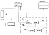
情報対応付け装置10を含むカメラシステムのハードウェアの構成の一例について、図8のブロック図に基づいて説明する。カメラシステムは複数の監視カメラ2とサーバー3と情報対応付け装置10とをハブ4でつないだものである。
An example of the hardware configuration of the camera system including the
図8に示すように、情報対応付け装置10はCPU71、取得画像から対象を検出する検出プログラムなどを記憶するROM72、RAM73、画像取得用のインタフェイスであるI/F74、バス75とを備えており、通常のコンピュータを利用したハードウェア構成となっている。なお、CPU71、ROM72、RAM73、I/F74はバス75を介して互いに接続されている。
As illustrated in FIG. 8, the
情報対応付け装置10では、CPU71が、ROM72からプログラムをRAM73上に読み出して実行することにより、上記各部(取得部11、解析部12、検出部13、対応付け部14、記憶部15、出力部16等)がコンピュータ上で実現され、I/F74から検出処理を行う。
In the
なお、プログラムはROM72に記憶されていてもよい。また、プログラムを、インターネット等のネットワークに接続されたコンピュータ上に格納し、ネットワーク経由でダウンロードさせることにより提供するようにしてもよい。また、プログラムを、インターネット等のネットワーク経由で提供又は配布するようにしてもよい。
The program may be stored in the
また、情報対応付け装置10が複数あり、それらとハブ4をつないであってもよい。
Moreover, there may be a plurality of
また、図9に示すように監視カメラ2が、ハブ4ではなく情報対応付け装置10と直接接続する構成でもよい。
Further, as shown in FIG. 9, the
第2の実施形態の情報対応付け装置20について図10〜図12に基づいて説明する。
An
情報対応付け装置20の構成について図10のブロック図に基づいて説明する。情報対応付け装置20は、取得部21、解析部22、検出部23、対応付け部24、記憶部25、出力部26を備える。この中で取得部21、解析部22及び検出部23はそれぞれ、第1の実施形態の情報対応付け装置10の取得部11、解析部12、検出部13と同じ構成と機能であるので、その説明は省略する。
The configuration of the
対応付け部24は、検出部23からの正面を向いた方向性パターンの有無と、解析部12からの属性情報と、監視カメラ2の個体識別情報の組を構成して記憶部25に記憶させる。例えば、対応付け部24は、図11に示す監視カメラ2の個体識別情報と属性情報と方向性パターンの検出結果の組テーブルを記憶部25に記憶させる。ここで方向性パターンの検出結果とは、正面向きの方向性パターンが検出されたか否かを意味する。
The associating
出力部26は、取得部11で取得された取得画像などの出力情報を出力するときに、その取得画像を撮影した監視カメラ2の個体識別情報と方向性パターンの有無を記憶部15から呼び出し、前記出力情報と共に出力する。
When the
情報対応付け装置20の処理について図12のフローチャートに基づいて説明する。
The processing of the
ステップS21〜S24は、第1の実施形態のステップS11〜S14の処理と同様であるので説明は省略する。 Steps S21 to S24 are the same as the processing of steps S11 to S14 of the first embodiment, and thus description thereof is omitted.
ステップS25において、検出部13は、取得画像から正面を向いた方向性パターンの有無を検出する。そして、ステップS26に進む。
In step S25, the
ステップS26において、対応付け部14が、正面を向いた方向性パターンの有無と、解析部12で解析した属性情報と、取得部11からの監視カメラ2の個体識別情報を対応付けて組を構成し、記憶部15に記憶させる。そして、ステップS27に進む。
In step S <b> 26, the
ステップS27において、対応付け部24は、建物1内の全ての監視カメラ2の個体識別情報と属性情報との組が記憶部25に記憶できたか否かを個体識別情報の総数Mから判断し、記憶数m=総数Mである場合には記憶できたとしてステップS29に進み(Nの場合)、M>mのときは記憶できていないとしてステップS28に進む(Yの場合)。
In step S27, the associating
ステップS28において、対応付け部14は、m=m+1としてステップS21に進み、作業者が提示板を持って次の監視カメラ2の前に立つ。
In step S <b> 28, the associating
ステップS29において、出力部26は、取得部21で取得された取得画像などの出力情報と、正面を向いた方向性パターンの有無と、その取得画像を撮影した監視カメラ2の個体識別情報を出力して終了する。
In step S29, the
本実施形態によれば、正面を向いた方向性パターンが検出された取得画像のみならず他の方向性パターンに対応した個体識別情報と属性情報の組も記憶できる。 According to the present embodiment, not only an acquired image in which a directional pattern facing the front is detected, but also a set of individual identification information and attribute information corresponding to another directional pattern can be stored.
第3の実施形態の情報対応付け装置3について図13、図14に基づいて説明する。
An
上記各実施形態では、検出部13では正面を向いた方向性パターンを検出したが、監視カメラ2の中には、天井に取り付けられ、作業者の正面を撮影できないものもある。この場合には、検出部13は、正面を向いた方向性パターンを検出するのでなく、真上を向いた方向性パターンを検出する。
In each of the embodiments described above, the
例えば、図13、又は、図14に示すように、監視カメラ2は、属性情報表現体を記載した提示板53又は提示板54を持った作業者の頭52や帽子55の画像を撮影して、取得部11が、その画像とその監視カメラ2の個体識別情報を取得する。
For example, as shown in FIG. 13 or FIG. 14, the
解析部12は、取得画像に写った提示板53又は提示板54の属性情報表現体から属性情報を解析する。
The
検出部13は、取得画像に写った作業者の頭52や帽子55の形状が、円形のときは真上と判断し、対応付け部14にその旨を出力する。
The
対応付け部14は、真上を向いた方向性パターンを検出できたので、属性情報と監視カメラ2の個体識別情報とを対応付けて組を構成し、記憶部15に記憶させる。
Since the associating
本実施形態によれば、正面のみならず真上に向いた方向性パターンを検出して、それら取得画像に対応した個体識別情報と属性情報の組のみを記憶するため、作業者が意図した天井に取り付けられた監視カメラ2だけに属性情報を付与できる。
According to the present embodiment, not only the front but also the directivity pattern facing directly above is detected, and only the set of individual identification information and attribute information corresponding to those acquired images is stored, so that the ceiling intended by the operator Attribute information can be given only to the
上記各実施形態では、監視カメラ2で説明したが、これに限らず、他のカメラのシステムで本実施形態を適応してもよい。
In each of the above embodiments, the
また、検出部13が、方向性パターンを検出するときに、方向性パターンの大きさや取得画像中の位置も考慮してもよい。例えば、取得画像中の中央でのみ上記の検出を行うことで、検出位置を指定してもよい。また、テンプレートの大きさを特定のものにすることで、検出する大きさを指定してもよい。
Further, when the
また、カメラは可視光のカメラに限らず、赤外線カメラを含めてもよい。 The camera is not limited to a visible light camera, but may include an infrared camera.
また、検出部13が検出する方向性パターンに関しては、上記実施形態では正面、真上で説明したが、これ以外の特定の方向を検出できるようにしてもよい。例えば、作業者の真横などである。
Moreover, although the directivity pattern detected by the
また、上記各実施形態では、監視カメラ2を建物1内に設置したが、これに代えて、建物1の外、例えば、公園、スポーツ施設、道路などに設置してもよく、また、船舶、航空機、自動車内部などに設置してもよい。
Moreover, in each said embodiment, although the
また、上記実施形態では、属性情報表現体を提示板に記載したが、監視カメラ2の数が多い場合には、この提示板を多数用意する必要があって手間となるため、各監視カメラ2毎に属性情報表示体をタブレット端末やノートパソコンなどの表示画面に表示させてもよい。また、方向性パターンも同様にタブレット端末などの表示画面に表示させてもよい。
In the above embodiment, the attribute information representation is described on the presentation board. However, when there are a large number of
上記では本発明の一実施形態を説明したが、この実施形態は、例として提示したものであり、発明の範囲を限定することは意図していない。これら新規な実施形態は、その他の様々な形態で実施されることが可能であり、発明の主旨を逸脱しない範囲で、種々の省略、置き換え、変更を行うことができる。これら実施形態やその変形は、発明の範囲や要旨に含まれると共に、特許請求の範囲に記載された発明とその均等の範囲に含まれる。 Although one embodiment of the present invention has been described above, this embodiment is presented as an example and is not intended to limit the scope of the invention. These novel embodiments can be implemented in various other forms, and various omissions, replacements, and changes can be made without departing from the spirit of the invention. These embodiments and modifications thereof are included in the scope and gist of the invention, and are included in the invention described in the claims and the equivalents thereof.
Claims (21)
前記画像から属性情報表現体を検出し、複数の属性情報表現体と属性情報を予め対応付けた属性テーブルに基づき前記検出された属性情報表現体に対応する属性情報を抽出し、
前記画像から方向性パターンを検出し、
前記方向性パターンが前記カメラに対し予め決められた特定の方向を向いていると判定された場合、前記カメラの個体識別情報と抽出された前記属性情報とを対応付ける、
情報対応付け装置。 Get images taken with the camera,
Detecting an attribute information representation from the image, extracting attribute information corresponding to the detected attribute information representation based on an attribute table in which a plurality of attribute information representations and attribute information are associated in advance;
Detecting a directional pattern from the image;
When it is determined that the directional pattern faces a predetermined direction with respect to the camera, the individual identification information of the camera is associated with the extracted attribute information.
Information association device.
請求項1に記載の情報対応付け装置。 Extracting attribute information of the camera from an attribute information representation included in the image;
The information matching apparatus according to claim 1.
請求項1又は2に記載の情報対応付け装置。 When the directional pattern is a pattern facing the front with respect to the camera, the individual identification information of the camera and the attribute information are associated with each other.
The information matching apparatus according to claim 1 or 2.
請求項1乃至3のいずれか一項に記載の情報対応付け装置。 Storing a set in which the individual identification information of the camera is associated with the attribute information in a storage unit;
The information matching apparatus according to any one of claims 1 to 3.
請求項1乃至4のいずれか一項に記載の情報対応付け装置。 The directional pattern is a face or a person.
The information matching apparatus according to any one of claims 1 to 4.
請求項1乃至5のいずれか一項に記載の情報対応付け装置。 The directional pattern is a polygon, a circle, or a combination of a plurality of figures.
The information matching apparatus according to any one of claims 1 to 5.
請求項2に記載の情報対応付け装置。 The attribute information representation is an attribute pattern, barcode, or character string shown in the image.
The information matching apparatus according to claim 2.
請求項7に記載の情報対応付け装置。 The attribute pattern is a polygon, a circle, or a combination of a plurality of the figures.
The information matching apparatus according to claim 7 .
請求項1乃至8のいずれか一項に記載の情報対応付け装置。 The attribute information is an installation position, an installation floor, an installation height, a shooting target, or a shooting direction of the camera.
The information matching apparatus according to any one of claims 1 to 8.
請求項1乃至9のいずれか一項に記載の情報対応付け装置。 The individual identification information is a serial number assigned to the camera, a manufacturing number of the camera, an IP address, or a name on the network.
The information matching apparatus according to any one of claims 1 to 9.
請求項1乃至10のいずれか一項に記載の情報対応付け装置。 The camera is a camera that captures visible light or an infrared camera.
The information matching apparatus according to any one of claims 1 to 10.
請求項1乃至11のいずれか一項に記載の情報対応付け装置。 There are a plurality of the cameras, and each camera is photographing the same subject.
The information matching apparatus according to any one of claims 1 to 11.
請求項1乃至12のいずれか一項に記載の情報対応付け装置。 An output unit that outputs information related to the association between the individual identification information of the camera and the attribute information;
The information matching apparatus according to any one of claims 1 to 12.
請求項2に記載の情報対応付け装置。 Analyzing the attribute information of the camera from the attribute information representation by template matching using an attribute threshold.
The information matching apparatus according to claim 2.
請求項14に記載の情報対応付け装置。 By template matching using a directional threshold, it is detected whether the directional pattern is a front surface, and the directional threshold is higher than the attribute threshold.
The information matching apparatus according to claim 14.
前記画像から属性情報表現体を検出し、複数の属性情報表現体と属性情報を予め対応付けた属性テーブルに基づき前記検出された属性情報表現体に対応する属性情報を抽出し、
前記画像から方向性パターンを検出し、
前記方向性パターンが前記カメラに対し予め決められた特定の方向を向いていると判定された場合、前記カメラの個体識別情報と抽出された前記属性情報とを対応付ける、
情報対応付け方法。 Get images taken with the camera,
Detecting an attribute information representation from the image, extracting attribute information corresponding to the detected attribute information representation based on an attribute table in which a plurality of attribute information representations and attribute information are associated in advance;
Detecting a directional pattern from the image;
When it is determined that the directional pattern faces a predetermined direction with respect to the camera, the individual identification information of the camera is associated with the extracted attribute information.
Information association method.
請求項16に記載の情報対応付け方法。 Extracting attribute information of the camera from an attribute information representation included in the image;
The information association method according to claim 16.
請求項16又は17に記載の情報対応付け方法。 When the directional pattern is a pattern facing the front with respect to the camera, the individual identification information of the camera and the attribute information are associated with each other.
The information correlation method according to claim 16 or 17.
前記画像から属性情報表現体を検出し、複数の属性情報表現体と属性情報を予め対応付けた属性テーブルに基づき前記検出された属性情報表現体に対応する属性情報を抽出し、
前記画像から方向性パターンを検出し、
前記方向性パターンが前記カメラに対し予め決められた特定の方向を向いていると判定された場合、前記カメラの個体識別情報と抽出された前記属性情報とを対応付ける機能、
をコンピュータで読み取り可能な非一時的な媒体に格納された情報対応付けプログラム。 Get images taken with the camera,
Detecting an attribute information representation from the image, extracting attribute information corresponding to the detected attribute information representation based on an attribute table in which a plurality of attribute information representations and attribute information are associated in advance;
Detecting a directional pattern from the image;
A function of associating the individual identification information of the camera with the extracted attribute information when it is determined that the direction pattern is oriented in a predetermined direction with respect to the camera;
Is an information association program stored in a non-transitory medium readable by a computer.
請求項19に記載の情報対応付けプログラム。 Extracting attribute information of the camera from an attribute information representation included in the image;
The information association program according to claim 19.
請求項19又は20に記載の情報対応付けプログラム。 When the directional pattern is a pattern facing the front with respect to the camera, the individual identification information of the camera and the attribute information are associated with each other.
The information association program according to claim 19 or 20.
Priority Applications (2)
| Application Number | Priority Date | Filing Date | Title |
|---|---|---|---|
| JP2013265617A JP6440937B2 (en) | 2013-12-24 | 2013-12-24 | Information association apparatus, method and program thereof |
| US14/575,437 US20150181170A1 (en) | 2013-12-24 | 2014-12-18 | Information associating apparatus, method thereof and program therefor |
Applications Claiming Priority (1)
| Application Number | Priority Date | Filing Date | Title |
|---|---|---|---|
| JP2013265617A JP6440937B2 (en) | 2013-12-24 | 2013-12-24 | Information association apparatus, method and program thereof |
Publications (2)
| Publication Number | Publication Date |
|---|---|
| JP2015122639A JP2015122639A (en) | 2015-07-02 |
| JP6440937B2 true JP6440937B2 (en) | 2018-12-19 |
Family
ID=53401538
Family Applications (1)
| Application Number | Title | Priority Date | Filing Date |
|---|---|---|---|
| JP2013265617A Active JP6440937B2 (en) | 2013-12-24 | 2013-12-24 | Information association apparatus, method and program thereof |
Country Status (2)
| Country | Link |
|---|---|
| US (1) | US20150181170A1 (en) |
| JP (1) | JP6440937B2 (en) |
Families Citing this family (1)
| Publication number | Priority date | Publication date | Assignee | Title |
|---|---|---|---|---|
| WO2018142599A1 (en) * | 2017-02-03 | 2018-08-09 | 三菱電機株式会社 | Information acquisition system and device |
Family Cites Families (16)
| Publication number | Priority date | Publication date | Assignee | Title |
|---|---|---|---|---|
| JP2003324713A (en) * | 2002-05-01 | 2003-11-14 | Matsushita Electric Ind Co Ltd | Video system and camera apparatus |
| JP4971594B2 (en) * | 2004-03-31 | 2012-07-11 | キヤノン株式会社 | Program and display control device |
| JP2006059185A (en) * | 2004-08-20 | 2006-03-02 | Rise Corp | Data management system and method |
| US8933967B2 (en) * | 2005-07-14 | 2015-01-13 | Charles D. Huston | System and method for creating and sharing an event using a social network |
| JP4958497B2 (en) * | 2006-08-07 | 2012-06-20 | キヤノン株式会社 | Position / orientation measuring apparatus, position / orientation measuring method, mixed reality presentation system, computer program, and storage medium |
| US8115812B2 (en) * | 2006-09-20 | 2012-02-14 | Panasonic Corporation | Monitoring system, camera, and video encoding method |
| JP2008129882A (en) * | 2006-11-21 | 2008-06-05 | Sanyo Electric Co Ltd | Imaging apparatus specification method, imaging apparatus specification device using the same, car navigation device, and image display system |
| US9848172B2 (en) * | 2006-12-04 | 2017-12-19 | Isolynx, Llc | Autonomous systems and methods for still and moving picture production |
| WO2008069224A1 (en) * | 2006-12-06 | 2008-06-12 | Nec Corporation | Information concealing device, method, and program |
| JP2010114584A (en) * | 2008-11-05 | 2010-05-20 | Mitsubishi Electric Corp | Camera device |
| WO2012096166A1 (en) * | 2011-01-11 | 2012-07-19 | パナソニック株式会社 | Image capturing system, camera control device for use therein, image capturing method, camera control method, and computer program |
| US9420275B2 (en) * | 2012-11-01 | 2016-08-16 | Hexagon Technology Center Gmbh | Visual positioning system that utilizes images of a working environment to determine position |
| US20140211018A1 (en) * | 2013-01-29 | 2014-07-31 | Hewlett-Packard Development Company, L.P. | Device configuration with machine-readable identifiers |
| JP6188452B2 (en) * | 2013-06-28 | 2017-08-30 | キヤノン株式会社 | Image processing apparatus, image processing method, and program |
| US8982177B2 (en) * | 2013-07-08 | 2015-03-17 | Avaya Inc. | System and method for whiteboard collaboration |
| JP6324025B2 (en) * | 2013-11-05 | 2018-05-16 | キヤノン株式会社 | Information processing apparatus and information processing method |
-
2013
- 2013-12-24 JP JP2013265617A patent/JP6440937B2/en active Active
-
2014
- 2014-12-18 US US14/575,437 patent/US20150181170A1/en not_active Abandoned
Also Published As
| Publication number | Publication date |
|---|---|
| US20150181170A1 (en) | 2015-06-25 |
| JP2015122639A (en) | 2015-07-02 |
Similar Documents
| Publication | Publication Date | Title |
|---|---|---|
| JP6534499B1 (en) | MONITORING DEVICE, MONITORING SYSTEM, AND MONITORING METHOD | |
| CN106372662B (en) | Detection method and device for wearing of safety helmet, camera and server | |
| US10885312B2 (en) | Face recognition system, face recognition method, display control apparatus, display control method, and display control program | |
| WO2020215552A1 (en) | Multi-target tracking method, apparatus, computer device, and storage medium | |
| JP6517666B2 (en) | Article management device, method thereof, and program thereof | |
| US20170104915A1 (en) | Display control apparatus, display control method, and storage medium | |
| US20150262068A1 (en) | Event detection apparatus and event detection method | |
| EA018349B1 (en) | Method for video analysis | |
| US9036875B2 (en) | Traffic control apparatus, method thereof, and program therefor | |
| US10558846B2 (en) | Face collation device, face collation system comprising same, and face collation method | |
| WO2019220589A1 (en) | Video analysis device, video analysis method, and program | |
| JP6494418B2 (en) | Image analysis apparatus, image analysis method, and program | |
| JP7131587B2 (en) | Information processing system, information processing device, information processing method and program | |
| JP6503079B2 (en) | Specific person detection system, specific person detection method and detection device | |
| KR20160057867A (en) | Display apparatus and image processing method thereby | |
| CN112184773A (en) | Helmet wearing detection method and system based on deep learning | |
| WO2020137193A1 (en) | Human detection device and human detection method | |
| US11227007B2 (en) | System, method, and computer-readable medium for managing image | |
| CN115862113A (en) | Stranger abnormity identification method, device, equipment and storage medium | |
| US20220076005A1 (en) | Person authentication apparatus, control method, and non-transitory storage medium | |
| TWI620148B (en) | Device and method for monitoring, method for counting people at a location | |
| JP6440937B2 (en) | Information association apparatus, method and program thereof | |
| CN111582278A (en) | Portrait segmentation method and device and electronic equipment | |
| US9805245B2 (en) | Image resolution recognition device, method for recognizing image resolution and image resolution recognition program | |
| JP2015184944A (en) | Person detection device |
Legal Events
| Date | Code | Title | Description |
|---|---|---|---|
| A621 | Written request for application examination |
Free format text: JAPANESE INTERMEDIATE CODE: A621 Effective date: 20160825 |
|
| A977 | Report on retrieval |
Free format text: JAPANESE INTERMEDIATE CODE: A971007 Effective date: 20170410 |
|
| A131 | Notification of reasons for refusal |
Free format text: JAPANESE INTERMEDIATE CODE: A131 Effective date: 20170606 |
|
| A521 | Request for written amendment filed |
Free format text: JAPANESE INTERMEDIATE CODE: A523 Effective date: 20170703 |
|
| A131 | Notification of reasons for refusal |
Free format text: JAPANESE INTERMEDIATE CODE: A131 Effective date: 20180109 |
|
| A521 | Request for written amendment filed |
Free format text: JAPANESE INTERMEDIATE CODE: A523 Effective date: 20180307 |
|
| A131 | Notification of reasons for refusal |
Free format text: JAPANESE INTERMEDIATE CODE: A131 Effective date: 20180918 |
|
| A521 | Request for written amendment filed |
Free format text: JAPANESE INTERMEDIATE CODE: A523 Effective date: 20181009 |
|
| TRDD | Decision of grant or rejection written | ||
| A01 | Written decision to grant a patent or to grant a registration (utility model) |
Free format text: JAPANESE INTERMEDIATE CODE: A01 Effective date: 20181023 |
|
| A61 | First payment of annual fees (during grant procedure) |
Free format text: JAPANESE INTERMEDIATE CODE: A61 Effective date: 20181121 |
|
| R151 | Written notification of patent or utility model registration |
Ref document number: 6440937 Country of ref document: JP Free format text: JAPANESE INTERMEDIATE CODE: R151 |
|
| R250 | Receipt of annual fees |
Free format text: JAPANESE INTERMEDIATE CODE: R250 |