JP6440423B2 - Heat source equipment - Google Patents
Heat source equipment Download PDFInfo
- Publication number
- JP6440423B2 JP6440423B2 JP2014190052A JP2014190052A JP6440423B2 JP 6440423 B2 JP6440423 B2 JP 6440423B2 JP 2014190052 A JP2014190052 A JP 2014190052A JP 2014190052 A JP2014190052 A JP 2014190052A JP 6440423 B2 JP6440423 B2 JP 6440423B2
- Authority
- JP
- Japan
- Prior art keywords
- heat exchanger
- water
- hot water
- combustion
- heat
- Prior art date
- Legal status (The legal status is an assumption and is not a legal conclusion. Google has not performed a legal analysis and makes no representation as to the accuracy of the status listed.)
- Expired - Fee Related
Links
Images


Description
本発明は、熱交換器とバーナ装置とを備えた熱源装置に関するものである。 The present invention relates to a heat source device including a heat exchanger and a burner device.
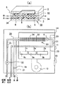
従来、ガスや石油等の燃料を燃焼させるバーナ装置を備えた様々な熱源装置が用いられている(例えば特許文献1、参照)。図2には、熱源装置の一例が模式的なシステム図により示されている。この熱源装置はガス燃焼式の給湯器であり、器具ケース11内の燃焼室23に、バーナ装置1と、該バーナ装置1の燃焼により発生する燃焼ガスによって加熱される給湯用の熱交換器4,5が設けられている。この例では、熱交換器4はバーナ装置1の燃焼ガスの潜熱を回収する潜熱回収用給湯熱交換器であり、熱交換器5は、バーナ装置1の燃焼ガスの顕熱を回収する顕熱回収用給湯熱交換器である。
2. Description of the Related Art Conventionally, various heat source devices including a burner device that burns fuel such as gas and oil have been used (see, for example, Patent Document 1). FIG. 2 is a schematic system diagram showing an example of the heat source device. This heat source device is a gas combustion type water heater, and in the
熱交換器4の水導入側には給水通路19が接続され、熱交換器4の水導出側(熱交換器5の水導入側)には熱交換器5への液体導入通路としての通路20が接続され、熱交換器5の水導出側には液体導出通路としての給湯通路21が接続されている。そして、給水通路19から導入されて熱交換器4を通って加熱された水を熱交換器5に導入した後、該熱交換器5を通って加熱された水を通路(給湯通路)21を介して給湯先に導く給湯回路28が形成されている。
A
なお、燃焼室11の下部側にはバーナ装置1への給排気用の燃焼ファン13が設けられており、燃焼ファン13の駆動によって器具ケース11の吸気口15から吸気される空気が図の破線矢印に示されるようにバーナ装置1に送られ、バーナ装置1の燃焼ガスが熱交換器4,5を通って排気口14から排出される。
A
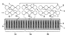
この給湯器において、バーナ装置1は、複数の燃焼面(区分燃焼面)2a,2b,2cを有しており、それぞれの燃焼面2a,2b,2cは、図9(a)に示されるように、バーナ8a,8b,8cを図のX方向に5つずつ配列して形成されたバーナ群3a,3b,3cの燃焼面により形成されている。各バーナ8a,8b,8cは、複数の炎口9の列を一列以上(この図では一列)各バーナ8a,8b,8cの長手方向(図のY方向)に沿って配設して形成されている。
In this water heater, the
また、図9(b)に示されるように、熱交換器5は、液体流通用管路としての水管(通水管路)6を有しており、水管6には液体(液体の熱媒体)としての水が通され、この水がバーナ装置1の燃焼ガスにより加熱される。水管6は、図のX方行に直線状に伸長した複数の管路部位7と、隣り合う管路部位7同士を接続するU字型の曲管路部位18とを有しており、管路部位7がバーナ8a,8b,8cの炎口9の列と略直交する態様に配設されている。
As shown in FIG. 9B, the
つまり、図9(a)には、水管6のうち直線状の管路部位7の断面のみが示されているが、実際には、図9(b)に示されるような態様を有し、水管6は、図9(a)の矢印に示されるように、熱交換器5の一端側から他端側に向けて水管6内を液体が蛇行しながら流れるように、熱交換器5の一端側から他端側にかけて蛇行しながら配設されている。なお、熱交換器5には、必要に応じて管路部位7と略直交する方向にフィン(図示せず)が設けられる。
That is, in FIG. 9 (a), only the cross section of the
また、熱交換器4も同様に、直線状の管路部位と直線状の管路部位同士を接続する態様の曲管路部位とを有しており、熱交換器5の上側に配置されている。
Similarly, the
熱源装置には、図示されていない燃焼制御手段が設けられており、バーナ装置1の燃焼時には、燃焼制御手段の制御により燃焼ファン13(図2、参照)の駆動が行われると共に、バーナ装置1への燃料ガスの供給が行われるように、バーナ8a,8b,8cに接続されているガス管(図示せず)に設けられているガス電磁弁の開閉制御やガス比例弁の開弁量調節制御が行われる。
The heat source device is provided with combustion control means (not shown). When the
この燃焼制御に際し、燃焼制御手段は、バーナ装置1に要求される燃焼能力が一段アップする毎に燃焼面2a,2b,2cを予め定められた順番で選択的に順次追加燃焼させる燃焼面切り替えを行う。例えばバーナ装置1に要求される燃焼能力が小の時には中央の燃焼面2aのみを燃焼させ、要求される燃焼能力が中の時には燃焼面2aに加えて燃焼面2bも燃焼させ(燃焼面2a+2b)、要求される燃焼能力が大の時には燃焼面2a,2bに加えて燃焼面2cも燃焼させる(燃焼面2a+2b+2c)。
In this combustion control, the combustion control means performs combustion surface switching for selectively and additionally burning the
つまり、バーナ装置1の燃焼能力は段階的に定められており、燃焼制御装置は、バーナ装置1に要求される燃焼能力段がアップすると、燃焼させる燃焼面2a,2b,2cを順次増加させていく。また、各燃焼能力段において、それぞれ予め定められる範囲内で燃焼能力調節が可能と成しており、その燃焼能力の調節は、各バーナ群3a,3b,3cに接続されているガス管のガス比例弁の開弁量調節により行われる。
That is, the combustion capacity of the
なお、図9(a)に示されているバーナ装置1は、バーナ装置1に要求される燃焼能力が小の時に燃焼させるのは中央の燃焼面2aとしているが、以前は、バーナ装置1への点火用のイグナイタ電極をバーナ装置1の一端側に設けて、バーナ装置1に要求される燃焼能力が小の時にはイグナイタ電極に一番近い端側の燃焼面のみを燃焼させることが行われていた。
In the
しかしながら、以下の理由によって、最近では、バーナ装置1に要求される燃焼能力が小の時に中央の燃焼面のみを燃焼させる構成が主流となった。つまり、バーナが燃焼すると約1700℃の火炎が形成され、図10に示されるようなバーナの内胴29(図9等には図示せず)も輻射熱で加熱されるため、燃焼と停止とが繰り返されると熱応力により内胴29に亀裂が発生することがあるが、この亀裂の発生は、バーナ装置1に要求される燃焼能力が小の時に端側の燃焼面のみを燃焼させるもの方が、バーナ装置1に要求される燃焼能力が小の時に中央の燃焼面のみを燃焼させるものよりも起こりやすいのである。
However, for the following reasons, recently, a configuration in which only the central combustion surface is combusted when the combustion capacity required for the
つまり、複数の燃焼面を有するバーナ装置1において、端側のバーナのみを燃焼させた場合には、その燃焼により、図10(a)の斜線部分に示されるコ字形状の部分の内胴29が輻射熱を受け、矢印に示されるように、輻射熱を受けた面と隣接する2面に熱を伝えることになるのに対し、中央側のバーナのみを燃焼させた場合には、その燃焼により図10(b)の斜線部分に示されるような内胴29の中央側の互いに対向する部分が輻射熱を受け、矢印に示されるように、輻射熱を受けた面と隣接する4面に熱を伝えることになる。
That is, in the
そのため、中央側のバーナのみを燃焼させる場合の方が端側のバーナのみを燃焼させる場合よりも輻射面を受ける面の面積が小さくなり、かつ、放熱性も向上するため、前記のようなバーナ燃焼時の輻射熱に起因する内胴29の亀裂が生じにくくなり、バーナ装置1の耐久性を向上させる(寿命を長くする)ことができる。そこで、バーナ装置1に要求される燃焼能力が小の時に中央の燃焼面のみを燃焼させる中央燃焼方式が主流となり、バーナ装置の耐久性が向上されている。なお、図10においては、バーナ装置1の炎口9等の図示が省略されている。
Therefore, the area for receiving the radiation surface is smaller and the heat dissipation is improved when only the burner at the center side is burned than when only the burner at the end side is burned. Cracks in the
ところで、例えば図9に示したような複数の燃焼面2a,2b,2cを備えたバーナ装置1を有し、その燃焼面2a,2b,2c切り替えを行う熱源装置において、例えば燃焼面2aのみの燃焼を行ったり、燃焼面2aと燃焼面2bの燃焼を行ったりする、いわゆる部分燃焼を行う場合、以下のようなことが生じる。
By the way, in a heat source device having a
例えば熱交換器5の水管6を通る水は、例えば燃焼面2a,2bが部分燃焼されている場合は、熱交換器5において上段に配置されている水管6のうち、燃焼されていない燃焼面2cの上側を通った後に、燃焼している燃焼面2a,2bの上側に配設されている水管6を通る。その後、熱交換器5において下段に配置されている水管6のうち、燃焼している燃焼面2a,2bの上側に配設されている水管6を通った後、燃焼されていない燃焼面2cの上側に配設されている水管6を通って導出されることになる。
For example, the water passing through the
しかしながら、バーナ装置1の燃焼時には、その燃焼面2a,2b,2cのいずれの面が燃焼しているかにかかわらず、前記の如く、燃焼ファン13の駆動が行われて燃焼ガスや空気が熱交換器4,5の水管6の間を通過していく。そのため、燃焼している燃焼面2a,2bの上側に配設されている水管6を通って燃焼ガスにより加熱された水が、燃焼されていない燃焼面2cの上側に配設されている水管6を通るときに、燃焼面2cの上側を通る高温ではない空気によって冷やされてしまうといった問題があった。
However, when the
つまり、せっかく加熱した熱(この熱により加熱された水管6内の水)を高温ではない空気によって冷やして排気の熱として熱源装置の外部に熱を逃がしてしまうことになる(加熱された水が冷やされることになる)ため、バーナ装置1の部分燃焼時の熱効率がその分だけ低下し、熱源装置の熱効率を低下させてしまうことになっていた。
That is, the heat heated (water in the
本発明は、上記課題を解決するためになされたものであり、その目的は、複数の燃焼面を有して燃焼能力段の変化に応じて燃焼面を切り替える機能を備えたバーナ装置を有する熱源装置において、バーナ装置の部分燃焼を行う際の熱効率を向上できる熱源装置を提供することにある。 The present invention has been made to solve the above-described problems, and an object of the present invention is to provide a heat source having a burner device having a plurality of combustion surfaces and a function of switching the combustion surfaces according to changes in the combustion capacity stage. An object of the present invention is to provide a heat source device capable of improving the thermal efficiency when performing partial combustion of a burner device.
本発明は上記目的を達成するために、次の構成をもって課題を解決する手段としている。すなわち、第1の発明は、複数の炎口が長手方向に沿って配列配置された炎口列を一列以上配設して成る燃焼面を備えたバーナが前記炎口列と直交する方向に並ぶ態様で複数配置されてバーナ装置が形成され、該バーナ装置の燃焼面は前記複数のバーナのうち一つのバーナの燃焼面または隣り合う複数のバーナの燃焼面毎に区分けされて、前記バーナ装置に要求される燃焼能力が一段アップする毎に前記区分燃焼面を予め定められた順番で選択的に順次追加燃焼させる燃焼制御手段を有し、前記バーナ装置の前記燃焼面の上側には該バーナ装置の燃焼により発生する燃焼ガスによって加熱される熱交換器が設けられて、該熱交換器に液体を導入する液体導入通路と前記熱交換器から液体を導出する液体導出通路とが設けられ、前記熱交換器を形成する液体流通用管路は前記バーナの前記炎口列と平行または略平行に伸長した管路部位を有して配設されるとともに前記バーナ装置の前記区分燃焼面に対応させて区画化された区画化管路と成し、前記バーナ装置による前記燃焼能力段が変化する毎の前記区分燃焼面の燃焼能力段変化に応じた燃焼順とは逆の順番で前記区画化管路毎に液体が通されるように該区画化管路同士が互いに接続されており、前記液体流通用管路は液体としての水を流通する通水管路を有して、該通水管路を通る水をバーナ装置の燃焼ガスにより加熱する給湯用の熱交換器が形成され、該給湯用の熱交換器を通って加熱された水を給湯先に導く給湯回路が形成され、該給湯回路には、該給湯回路内の水抜きを行う水抜き栓が前記給湯用の熱交換器への水導入側と該給湯用の熱交換器からの水導出側とにそれぞれ設けられ、該給湯用の熱交換器の前記通水管路の途中部には該通水管路に空気を導入する空気導入手段が接続されており、前記水抜き栓の開状態で前記空気導入手段から空気を導入することによって前記給湯用の熱交換器の通水管路の水を前記水抜き栓から導出して水抜きを行う水抜き制御手段が設けられている構成をもって課題を解決するための手段としている。 In order to achieve the above object, the present invention has the following configuration as means for solving the problems. That is, according to the first aspect of the present invention, a burner having a combustion surface formed by arranging one or more flame mouth rows in which a plurality of flame mouths are arranged along the longitudinal direction is arranged in a direction perpendicular to the flame mouth rows. A plurality of burner devices are formed in the embodiment, and a combustion surface of the burner device is divided into a combustion surface of one burner or a combustion surface of a plurality of adjacent burners among the plurality of burners, and the burner device Combustion control means for selectively and additionally burning the sectioned combustion surface in a predetermined order every time the required combustion capacity is increased by one stage, and the burner device above the combustion surface of the burner device A heat exchanger heated by the combustion gas generated by the combustion of is provided, a liquid introduction passage for introducing liquid into the heat exchanger, and a liquid outlet passage for extracting liquid from the heat exchanger are provided, Heat exchanger The liquid distribution conduit formed is provided with a conduit portion extending in parallel or substantially parallel to the flame mouth row of the burner, and is partitioned to correspond to the section combustion surface of the burner device. Each compartmented pipe in a reverse order to the combustion order corresponding to the change in the combustion capacity stage of the section combustion surface each time the combustion capacity stage of the burner device changes. The partitioning pipes are connected to each other such that the liquid flow pipe has a water flow pipe for flowing water as a liquid, and the water passing through the water flow pipe is burned. A hot water supply heat exchanger that is heated by the combustion gas of the device is formed, and a hot water supply circuit that leads water heated through the hot water supply heat exchanger to a hot water supply destination is formed, and the hot water supply circuit includes the hot water supply circuit A drain plug for draining water in the circuit has a water introduction side to the hot water heat exchanger. Provided on the water outlet side from the heat exchanger for hot water supply, and an air introduction means for introducing air into the water conduit is connected to the middle part of the water conduit of the heat exchanger for hot water supply. And a drain control for draining water from the drain plug by introducing air from the air introduction means in the open state of the drain plug to the water conduit of the heat exchanger for hot water supply. A configuration provided with means is used as means for solving the problem.
さらに、第2の発明は、前記第1の発明の構成に加え、前記給湯用の熱交換器は、バーナの燃焼ガスの顕熱を回収する顕熱回収用給湯熱交換器と前記バーナの燃焼ガスから潜熱を回収する潜熱回収用給湯熱交換器とを有し、該潜熱回収用給湯熱交換器を通って加熱された水を顕熱回収用給湯熱交換器に導入する構成を有し、給湯回路には該給湯回路内の水抜きを行う水抜き栓が前記潜熱回収用給湯熱交換器への水導入側と前記顕熱回収用給湯熱交換器からの水導出側とにそれぞれ設けられ、該顕熱回収用給湯熱交換器の通水用の管路の途中部には該通水用の管路に空気を導入する空気導入手段が接続されており、前記水抜き栓の開状態で前記空気導入手段から空気を導入することによって、該空気導入手段の配設位置よりも前記潜熱回収用給湯熱交換器への水導入側寄りの管路内の水は該潜熱回収用給湯熱交換器への水導入側に設けられた水抜き栓側から導出され、前記空気導入手段の配設位置よりも前記顕熱回収用給湯熱交換器の水導出側寄りの管路内の水は該顕熱回収用給湯熱交換器の水導出側に設けられた水抜き栓側から導出されるようにする水抜き制御手段が設けられていることを特徴とする。 Further, in the second invention, in addition to the configuration of the first invention, the heat exchanger for hot water supply includes a sensible heat recovery hot water supply heat exchanger for recovering sensible heat of combustion gas of the burner, and combustion of the burner. A latent heat recovery hot water supply heat exchanger that recovers latent heat from the gas, and has a configuration for introducing water heated through the latent heat recovery hot water supply heat exchanger into the sensible heat recovery hot water supply heat exchanger, In the hot water supply circuit, drain plugs for draining water in the hot water supply circuit are provided respectively on the water introduction side to the latent heat recovery hot water supply heat exchanger and the water outlet side from the sensible heat recovery hot water supply heat exchanger. In addition, air introduction means for introducing air into the water conduit is connected to an intermediate portion of the water conduit of the hot water heat exchanger for recovering sensible heat, and the drain plug is opened. By introducing air from the air introduction means, the latent heat recovery supply is made more than the position of the air introduction means. The water in the pipe line near the water introduction side to the heat exchanger is led out from the drain plug side provided on the water introduction side to the hot water heat exchanger for latent heat recovery, and from the position of the air introduction means The water in the pipe line near the water outlet side of the sensible heat recovery hot water supply heat exchanger is led out from the drain plug side provided on the water outlet side of the sensible heat recovery hot water heat exchanger. A drainage control means is provided.
さらに、第3の発明は、前記第2の発明の構成に加え、前記空気導入手段は、潜熱回収用給湯熱交換器への水導入側に設けられた水抜き栓側から導出される水の導出に要する時間と顕熱回収用給湯熱交換器の水導出側に設けられた水抜き栓側から導出される水の導出に要する時間とが同じ値またはほぼ同じ値となる位置に設けられていることを特徴とする。 Furthermore, in the third invention, in addition to the configuration of the second invention, the air introduction means is configured to supply water drawn from a drain plug side provided on the water introduction side to the hot water heat exchanger for latent heat recovery. The time required for the derivation and the time required for the derivation of water derived from the drain plug side provided on the water outlet side of the hot water heat exchanger for sensible heat recovery are set at the same value or almost the same value. It is characterized by being.
さらに、第4の発明は、前記第2または第3のいずれか一つの発明の構成に加え、暖房装置に供給される液体の熱媒体を循環する機能を備えた暖房用液体循環回路を有し、該暖房用液体循環回路には前記熱媒体を循環させる暖房用循環ポンプと、前記熱媒体を加熱する暖房用熱交換器とが設けられ、該暖房用熱交換器が給湯用の熱交換器の顕熱回収用給湯熱交換器と一体化されて一缶二水路型の熱交換器が形成されていることを特徴とする。 Furthermore, a fourth invention has a heating liquid circulation circuit having a function of circulating a liquid heat medium supplied to the heating device in addition to the configuration of any one of the second and third inventions. The heating liquid circulation circuit is provided with a heating circulation pump for circulating the heat medium, and a heating heat exchanger for heating the heat medium, and the heating heat exchanger is a heat exchanger for hot water supply. It is characterized by being integrated with a sensible heat recovery hot water supply heat exchanger to form a one-can two-water channel heat exchanger.
本発明の熱源装置においては、複数の炎口が長手方向に沿って配列配置された炎口列を一列以上配設して成る燃焼面を備えたバーナを前記炎口列と直交する方向に並ぶ態様で複数配置してバーナ装置が形成され、該バーナ装置の燃焼面は前記複数のバーナのうち一つのバーナの燃焼面または隣り合う複数のバーナの燃焼面毎に区分けされて、前記バーナ装置に要求される燃焼能力が一段アップする毎に前記区分燃焼面を予め定められた順番で選択的に順次追加燃焼させる構成を有し、バーナ装置の前記燃焼面の上側に、該バーナ装置の燃焼により発生する燃焼ガスによって加熱される熱交換器が設けられているが、この熱交換器が特徴的な構成を有している。 In the heat source device of the present invention, a burner having a combustion surface in which one or more flame mouth rows in which a plurality of flame mouths are arranged in the longitudinal direction is arranged is arranged in a direction perpendicular to the flame mouth row. A burner device is formed by arranging a plurality of burners in the aspect, and a combustion surface of the burner device is divided into a combustion surface of one burner or a combustion surface of a plurality of adjacent burners among the plurality of burners, and the burner device Each time the required combustion capacity is increased by one stage, the section combustion surface is selectively and additionally burned in a predetermined order, and the burner device is burned above the combustion surface by combustion of the burner device. A heat exchanger heated by the generated combustion gas is provided, and this heat exchanger has a characteristic configuration.
つまり、熱交換器には液体を導入する液体導入通路と前記熱交換器から液体を導出する液体導出通路とが設けられているが、熱交換器を形成する液体流通用管路は前記バーナの前記炎口列と平行または略平行に伸長した管路部位を有して配設されるとともに前記バーナ装置の前記区分燃焼面に対応させて区画化された区画化管路と成しており、前記バーナ装置による前記燃焼能力段が変化する毎の前記区分燃焼面の燃焼能力段変化に応じた燃焼順とは逆の順番で前記区画化管路毎に液体が通されるように該区画化管路同士が互いに接続されている。 In other words, the heat exchanger is provided with a liquid introduction passage for introducing a liquid and a liquid outlet passage for extracting the liquid from the heat exchanger, but the liquid circulation conduit forming the heat exchanger is provided in the burner. It is arranged to have a pipe line part extending in parallel or substantially parallel to the flame mouth row, and is a compartmentalized pipe that is compartmentalized corresponding to the section combustion surface of the burner device, The compartmentalization is performed so that the liquid is passed through the compartmentalized pipes in the order opposite to the order of combustion according to the change in the combustion capacity stage of the section combustion surface every time the combustion capacity stage is changed by the burner device. The pipelines are connected to each other.
従来の熱源装置において、熱交換器の液体流通用管路は、バーナの炎口列と直交する方向に伸長した管路部位を有して配設され、液体流通用管路を通る液体がバーナの炎口列と直交する方向に伸長した管路部位を通りながら熱交換器の一端側から他端側に向けて蛇行して通っていき、液体流通用管路が上下に多段に配設されている場合は他端で折り返し、前記と同様にバーナの炎口列と直交する方向に伸長した管路部位を通りながら熱交換器の他端側から一端側に向けて蛇行して通っていく、といったことを繰り返すような態様に形成されていた。 In the conventional heat source device, the liquid circulation conduit of the heat exchanger is provided with a pipeline portion extending in a direction orthogonal to the burner row of burners, and the liquid passing through the liquid circulation conduit is burned. While passing through a pipe part extending in a direction perpendicular to the flame mouth row, the heat exchanger meanders from one end side to the other end side, and liquid circulation pipes are arranged in multiple stages vertically. If it is, it is folded at the other end, and in the same manner as described above, it passes through the pipe portion extending in the direction orthogonal to the flame outlet row of the burner, meandering from the other end side to the one end side of the heat exchanger. , And so on.
そのため、バーナ装置の部分燃焼時(複数の区分燃焼面を全て同時期に燃焼させるのではなく、一部の燃焼面のみを燃焼させて一部の燃焼面は燃焼させないとき)には、燃焼されている燃焼面上を通って加熱された液体が、その後に燃焼されていない燃焼面を通るときに、液体流通管路の周りを通る高温でない空気により冷やされてしまっていたが、本発明では、このように、せっかく加熱された液体が、加熱後に、加熱されていない空気によって冷やされることを防止できる。 Therefore, it is burned during the partial combustion of the burner device (when not burning all of the plurality of divided combustion surfaces at the same time, but burning only some combustion surfaces and not burning some combustion surfaces). In the present invention, the liquid heated through the combustion surface is cooled by the non-hot air that passes around the liquid flow line when passing through the non-combusted combustion surface. Thus, it is possible to prevent the heated liquid from being cooled by unheated air after heating.
つまり、本発明によれば、前記の如く、熱交換器を形成する液体流通用管路は前記バーナの前記炎口列と平行または略平行に伸長した管路部位を有し、バーナ装置の前記区分燃焼面に対応させて区画化された区画化管路と成して、バーナ装置による前記燃焼能力段が変化する毎の前記区分燃焼面の燃焼能力段変化に応じた燃焼順とは逆の順番で前記区画化管路毎に液体が通されるように該区画化管路同士が互いに接続されているので、バーナ装置の部分燃焼時には、液体は、燃焼していない燃焼面上の管路部位を通った後に、燃焼している燃焼面上の管路部位を通って導出されることになり、従来のように、液体は燃焼ガスにより加熱された後に、高温ではない空気によって冷やされることを防ぐことができる。そのため、バーナ装置の部分燃焼時の熱効率の高い熱源装置を実現できる。 That is, according to the present invention, as described above, the liquid circulation conduit forming the heat exchanger has a conduit portion extending in parallel or substantially parallel to the burner row of the burner, and Compartmented pipes that are partitioned in accordance with the segment combustion surface, and reverse to the combustion order according to the change in the combustion capability stage of the segment combustion surface each time the combustion capability stage is changed by the burner device Since the compartmentalized pipelines are connected to each other so that the liquid is passed through the compartmentalized pipelines in order, the liquid is a pipeline on the non-combusted combustion surface during partial combustion of the burner device. After passing through the part, it will be led out through the pipe part on the burning combustion surface, and as before, the liquid is heated by the combustion gas and then cooled by non-high temperature air Can be prevented. Therefore, a heat source device with high thermal efficiency at the time of partial combustion of the burner device can be realized.
なお、従来例で説明したように、最近では、区分燃焼面の燃焼順を例えばバーナ装置における中央配置の区分燃焼面が一番先に燃焼するように形成し、バーナ装置の耐久性向上を図るようにしていることが多い。 As described in the conventional example, recently, the combustion order of the divided combustion surfaces is formed such that the centrally arranged divided combustion surface in the burner device burns first, thereby improving the durability of the burner device. I often do so.
また、前記液体流通用管路は液体としての水を流通する通水管路を有して、該通水管路を通る水をバーナ装置の燃焼ガスにより加熱する給湯用の熱交換器を形成し、該給湯用の熱交換器を通って加熱された水を給湯先に導く給湯回路が形成されている場合、本発明の構成においては以下のことが生じる可能性がある。 Further, the liquid circulation conduit has a water conduit that circulates water as a liquid, and forms a heat exchanger for hot water supply that heats the water passing through the water conduit by the combustion gas of the burner device, When a hot water supply circuit for guiding water heated through the heat exchanger for hot water supply to a hot water supply destination is formed, the following may occur in the configuration of the present invention.
つまり、本発明では、熱交換器を形成する液体流通用管路が前記のように前記バーナ装置の前記区分燃焼面に対応させて区画化された区画化管路と成し、バーナ装置による前記燃焼能力段が変化する毎の前記区分燃焼面の燃焼能力段変化に応じた燃焼順とは逆の順番で前記区画化管路毎に液体が通されるように該区画化管路同士を互いに接続するので、例えばバーナの炎口と平行または略平行な管路部位同士を接続する曲線状の管路が斜めに配置される部位が形成されて、通水管路が上下方向に高低差を介して接続される部位が形成されることがある。 In other words, in the present invention, the liquid circulation conduit forming the heat exchanger is formed as a compartmentalized pipeline that is partitioned in correspondence with the compartment combustion surface of the burner device as described above. The compartmentalized pipes are connected to each other so that liquid is passed through the compartmented pipes in the order opposite to the combustion order corresponding to the combustion capacity stage change of the compartmented combustion surface every time the combustion capacity stage changes. Since the connection is made, for example, a portion in which a curved pipe line connecting the pipe parts parallel to or substantially parallel to the flame outlet of the burner is obliquely formed is formed, and the water pipe line passes through a height difference in the vertical direction. May be formed.
そして、その通水管路の高低差ゆえに、例えば冬に通水管路の凍結防止を行うため等に通水管路の水抜きする際の水抜きがしにくくなる(あるいは、水抜きが不可能な部分が形成される)ことがあるが、給湯用の熱交換器内の水抜きを行う水抜き栓を前記給湯用の熱交換器への水導入側と該給湯用の熱交換器からの水導出側とにそれぞれ設け、該給湯用の熱交換器の前記通水管路の途中部に、該通水管路に空気を導入する空気導入手段を接続することにより、前記水抜き栓の開状態で前記空気導入手段から空気を導入して前記給湯用の熱交換器の通水管路の水を前記水抜き栓から導出し、給湯用の熱交換器内の水抜き動作を容易に、かつ、迅速に行うことができる。 And because of the difference in the height of the water conduit, for example, in order to prevent the water conduit from freezing in winter, it becomes difficult to drain the water when draining the water conduit (or the portion where water cannot be drained). However, a drain plug for draining water in the hot water heat exchanger is provided with a water introduction side to the hot water heat exchanger and water extraction from the hot water heat exchanger. Each of the heat exchangers for hot water supply is connected to an air introduction means for introducing air into the water conduit to the middle portion of the water conduit so that the drain plug is opened. Air is introduced from the air introduction means, and the water in the water conduit of the hot water heat exchanger is led out from the drain plug, so that the water draining operation in the hot water heat exchanger can be easily and quickly performed. It can be carried out.
さらに、給湯用の熱交換器を、バーナの燃焼ガスの顕熱を回収する顕熱回収用給湯熱交換器と前記バーナの燃焼ガスから潜熱を回収する潜熱回収用給湯熱交換器とを有する構成として、該潜熱回収用給湯熱交換器を通って加熱された水を顕熱回収用給湯熱交換器に導入する構成とする本発明においては、以下のような構成を有することから、容易に、かつ、迅速に通水管路の水抜きを行うことができる。 Further, the hot water supply heat exchanger includes a sensible heat recovery hot water supply heat exchanger for recovering sensible heat of the burner combustion gas, and a latent heat recovery hot water supply heat exchanger for recovering latent heat from the burner combustion gas In the present invention configured to introduce water heated through the latent heat recovery hot water supply heat exchanger into the sensible heat recovery hot water supply heat exchanger, since it has the following configuration, And it is possible to quickly drain the water conduit.
つまり、水抜き栓を潜熱回収用給湯熱交換器への水導入側と顕熱回収用給湯熱交換器からの水導出側とにそれぞれ設けてこれらの水抜き栓を開き、水抜き制御手段による水抜き動作時に、顕熱回収用給湯熱交換器の通水用の管路の途中部に設けた空気導入手段から空気を導入して、該空気導入手段の配設位置よりも前記潜熱回収用給湯熱交換器への水導入側寄りの管路内の水は該潜熱回収用給湯熱交換器への水導入側に設けられた水抜き栓側から導出し、前記空気導入手段の配設位置よりも前記顕熱回収用給湯熱交換器の水導出側寄りの管路内の水は該顕熱回収用給湯熱交換器の水導出側に設けられた水抜き栓側から導出されるようにすることで、容易に、かつ、迅速に通水用の管路の水抜きを行うことができる。 That is, the drain plugs are provided on the water introduction side to the hot water heat exchanger for latent heat recovery and the water outlet side from the hot water heat exchanger for sensible heat recovery, respectively, and these drain plugs are opened, and the drain control means During the water draining operation, air is introduced from the air introducing means provided in the middle of the water passage pipe of the hot water heat exchanger for recovering sensible heat, and the latent heat collecting The water in the pipe near the water introduction side to the hot water supply heat exchanger is led out from the drain plug side provided on the water introduction side to the hot water supply heat exchanger for latent heat recovery, and the air introduction means is disposed. The water in the pipe line closer to the water outlet side of the sensible heat recovery hot water supply heat exchanger is led out from the drain plug side provided on the water outlet side of the sensible heat recovery hot water heat exchanger. By doing so, water can be drained from the conduit for water passage easily and quickly.
さらに、このように潜熱回収用給湯熱交換器を設けて、該潜熱回収用給湯熱交換器への水導入側と顕熱回収用給湯熱交換器からの水導出側とからそれぞれ水抜きを行う構成において、空気導入手段を、潜熱回収用給湯熱交換器への水導入側に設けられた水抜き栓側から導出される水の導出に要する時間と顕熱回収用給湯熱交換器の水導出側に設けられた水抜き栓側から導出される水の導出に要する時間とが同じ値またはほぼ同じ値となる位置に設けることにより、一方の水の導出に要する時間が遅い場合よりも全体としての水抜き速度を速くできる Further, the hot water supply heat exchanger for latent heat recovery is provided in this way, and water is drained from the water introduction side to the latent heat recovery hot water supply heat exchanger and the water outlet side from the sensible heat recovery hot water supply heat exchanger, respectively. In the configuration, the time required for the derivation of the water derived from the drain plug provided on the water introduction side to the latent heat recovery hot water supply heat exchanger and the water derivation of the sensible heat recovery hot water supply heat exchanger By providing it at a position where the time required for derivation of water derived from the drain tap side provided on the side is the same value or almost the same value, the time required for derivation of one of the water is slower as a whole Can drain water faster
また、このように潜熱回収用熱交換器を有する構成において、潜熱回収用給湯熱交換器の通水管路の水は、水抜き時に潜熱回収用給湯熱交換器の水導入側に向かって流れて導出されるが、潜熱回収用給湯熱交換器は顕熱回収用給湯熱交換器の上流側に設けられることから、位置的にも顕熱回収用給湯熱交換器の上部側に設けられることが多く、潜熱回収用給湯熱交換器の通水管路の水は、その配置態様の下側から上側に向かって流れていって導出されることになる。 Further, in such a configuration having the latent heat recovery heat exchanger, the water in the water conduit of the latent heat recovery hot water heat exchanger flows toward the water introduction side of the latent heat recovery hot water heat exchanger when draining. However, since the hot water supply heat exchanger for latent heat recovery is provided on the upstream side of the sensible heat recovery hot water supply heat exchanger, it may be provided on the upper side of the sensible heat recovery hot water supply heat exchanger. In many cases, the water in the water conduit of the hot water supply heat exchanger for latent heat recovery flows out from the lower side to the upper side of the arrangement mode and is led out.
ところが、潜熱回収用給湯熱交換器の通水管路は断面が略円形状の管路で径の大きさが例えば10mm程度で比較的大きいことから、水平方向に又は略水平方向に配置されている通水管路の下側に溜まっていた水(例えば管路の略円形状の断面における下から3分の1の高さ辺りまでに溜まっていた水)は、空気導入手段から空気が導入されても前記のように潜熱回収用給湯熱交換器の水導出側に設けられている水抜き栓側には流れずに留まり、空気導入による(エアパージによる)水抜き栓からの水の導出が終了した後に、前記とは逆方向に潜熱回収用給湯熱交換器の水導出側に向けて、つまり、上側から下側に向かって流れていく(落ちていく)。 However, since the water pipe of the hot water heat exchanger for collecting latent heat is a pipe having a substantially circular cross section and having a relatively large diameter of, for example, about 10 mm, it is arranged horizontally or substantially horizontally. The water that has accumulated in the lower side of the water conduit (for example, the water that has accumulated from the bottom of the substantially circular cross section of the conduit to about one third of the height) is introduced from the air introduction means. As described above, the water stays without flowing on the drain plug side provided on the water outlet side of the hot water heat exchanger for recovering latent heat, and the derivation of water from the drain plug by air introduction (by air purge) is completed. Later, it flows (falls) from the upper side to the lower side in the opposite direction to the water outlet side of the hot water heat exchanger for latent heat recovery.
そのため、例えば潜熱回収用給湯熱交換器と顕熱回収用給湯熱交換器との容量比が1:2である装置において空気導入手段を潜熱回収用給湯熱交換器と顕熱回収用給湯熱交換器との間に接続する等して、例えば潜熱回収用給湯熱交換器への水導入側に設けられた水抜き栓側から導出される水の量が少ない場合には、前記のように空気導入によって潜熱回収用給湯熱交換器の水導入側に設けられている水抜き栓からの水の導出が速く済み、この水の導出時に導出されずに管路内に留まった水が、顕熱回収用給湯熱交換器からの水抜きが終了する前に下側に流れて空気導入手段をふさいでしまうおそれがある。そうなると、顕熱回収用給湯熱交換器の水抜きが途中で終了する等、適切に行えない。 Therefore, for example, in an apparatus in which the capacity ratio of the latent heat recovery hot water supply heat exchanger and the sensible heat recovery hot water supply heat exchanger is 1: 2, the air introduction means is replaced with the latent heat recovery hot water supply heat exchanger and the sensible heat recovery hot water supply heat exchange. When the amount of water led out from the drain plug side provided on the water introduction side to the hot water heat exchanger for latent heat recovery, for example, is small, The introduction of water from the drain plug provided on the water introduction side of the hot water heat exchanger for recovering latent heat is quick, and the water remaining in the pipeline without being discharged at the time of this water removal is sensible heat. There is a possibility that the air introduction means may be blocked by flowing downward before draining water from the recovery hot water supply heat exchanger. In such a case, the drainage of the sensible heat recovery hot-water supply heat exchanger cannot be performed properly, for example, the water draining is terminated halfway.
それに対し、潜熱回収用給湯熱交換器への水導入側に設けられた水抜き栓側から導出される水の導出に要する時間と顕熱回収用給湯熱交換器の水導出側に設けられた水抜き栓側から導出される水の導出に要する時間とが同じ又はほぼ同じ量となる位置に空気導入手段を設けることにより、このような問題が発生することを防止できる。 On the other hand, the time required for the derivation of water derived from the drain plug side provided on the water introduction side to the hot water supply heat exchanger for latent heat recovery and the water derivation side of the sensible heat recovery hot water supply heat exchanger By providing the air introduction means at a position where the time required for the water led out from the drain plug side is the same or almost the same amount, it is possible to prevent such a problem from occurring.
さらに、給湯用の熱交換器を有して該給湯用の熱交換器が顕熱回収用給湯熱交換器を有する構成において、暖房装置に供給される液体の熱媒体を循環する機能を備えた暖房用液体循環回路を設け、該暖房用液体循環回路には前記熱媒体を循環させる暖房用循環ポンプと、前記熱媒体を加熱する暖房用熱交換器とを設け、該暖房用熱交換器を給湯用の熱交換器の顕熱回収用給湯熱交換器と一体化して一缶二水路型の熱交換器を形成することにより、一つのバーナ装置によって暖房用熱交換器と給湯用の熱交換器を加熱できるため、小型で効率の高い熱源装置を形成できる。 Furthermore, in the structure which has a heat exchanger for hot water supply, and the heat exchanger for hot water supply has a hot water heat exchanger for sensible heat recovery, it has a function of circulating a liquid heat medium supplied to the heating device. A heating liquid circulation circuit is provided, the heating liquid circulation circuit is provided with a heating circulation pump that circulates the heat medium, and a heating heat exchanger that heats the heat medium. By integrating a sensible heat recovery hot water supply heat exchanger of a hot water supply heat exchanger to form a canned and two-channel heat exchanger, a single burner unit exchanges heat for heating and hot water supply. Since the vessel can be heated, a small and highly efficient heat source device can be formed.
以下、本発明の実施の形態を図面に基づき実施例によって説明する。なお、本実施例の説明において、従来例と同一名称部分には同一符号を付し、その重複説明は省略または簡略化する。 Embodiments of the present invention will be described below with reference to the drawings. In the description of the present embodiment, the same reference numerals are assigned to the same names as those in the conventional example, and the duplicate description is omitted or simplified.
図1(a)には、本発明に係る熱源装置の一実施例に設けられているバーナ装置と熱交換器の一部構成が模式的な斜視説明図により示されている。本実施例の熱源装置は、例えば図2に示したようなシステム構成を有しており、本実施例の最も特徴的な構成は、バーナ装置1の構成と熱交換器5の構成を以下に述べる特徴的な構成としたことである。
FIG. 1A is a schematic perspective view showing a partial configuration of a burner device and a heat exchanger provided in an embodiment of a heat source device according to the present invention. The heat source device of the present embodiment has a system configuration as shown in FIG. 2, for example. The most characteristic configuration of the present embodiment is the configuration of the
本実施例において、バーナ装置1を形成する各バーナ8a,8b,8cは、熱交換器5の水管6の直線状の管路部位7と平行または略平行に配設されており(言い換えれば、管路部位7がバーナ8a,8b,8cの炎口9の列と平行または略平行に伸長形成されており)、図の左側から順に、8個(8本)のバーナ8cによりバーナ群3cが形成され、4個(4本)のバーナ8aによりバーナ群3aが形成され、10個(10本)のバーナ8bによりバーナ群3bが形成されている。
In the present embodiment, each
また、熱交換器5の水管6の管路部位7は、バーナ装置1の各バーナ群3a,3b,3cによって形成された各区分燃焼面2a,2b,2cに対応させて区画化された区画化管路22a,22b,22cと成しており、バーナ装置1による燃焼能力段が変化する毎の区分燃焼面2a,2b,2cの燃焼能力段変化に応じた燃焼順(区分燃焼面2a,2b,2cの順に順次追加燃焼していく順番)とは逆の順番で前記区画化管路22c,22b,22a毎に液体が通されるように該区画化管路22a,22b,22c同士が互いに接続されている。
Further, the
つまり、図1(a)では、熱交換器5の水管6の管路部位7は1本のみ示されているが、熱交換器5における水管6の管路部位7は、図のX方向に伸長形成されて、互いに間隔を介しながら平行(または略平行)に複数配設されており、本実施例においては、熱交換器5に、図1(a)の矢印Aに示されるように水が流れるように管路部位7同士が接続されている。
That is, in FIG. 1 (a), only one
なお、説明を分かりやすくするために、図1(a)の矢印Aは管路部位7同士を横切る態様で示されているが、実際には、例えば図1(b)の矢印Aに示されるように、管路部位7の一端側(例えば図の手前側)から他端側(例えば図の奥側)に流れた後、曲管路部位18を通り、管路部位7の他端側(例えば図の奥側)から一端側(例えば図の手前側)に流れ、その後、曲管路部位18を通るといったように、直線状の管路部位7と曲線状の曲管路部位18と交互に通って流れるように管路部位7同士が接続され、かつ、前記の如く区画化管路22a,22b,22c同士が互いに接続されている。
In order to make the explanation easy to understand, the arrow A in FIG. 1A is shown in a manner that crosses the
また、曲管路部位18の曲率半径は大きい方が好ましく、例えば図3に示されるように、直線状の管路部位7を上下に曲管路部位18で接続するも斜め又は水平方向に並べて配置されている管路部位7同士が連通するように曲管路部位18により接続する方が好ましいため、本実施例では、図1(a)および図4(b)に示されるような接続態様としている。
Further, it is preferable that the
なお、図4(b)は、図1(a)に示されている本実施例のバーナ装置1と熱交換器5の構成をより分かりやすくするために、熱交換器5の断面図とバーナ装置1の平面図を組み合わせて模式的に示した図である。同図において、熱交換器5の水管6の各管路部位7の断面内(円内)には、説明の都合上、水の通る順番と、その順番に対応させたA〜Rのアルファベットとが共に示されている。なお、バーナ装置1の炎口9の配列長さ等は実際の態様と必ずしも一致せず、例えばバーナ装置1の縦方向(図のX方向)の長さと横方向(図のY方向)の長さの差は図4(b)に示すよりも小さく形成される(同図に示されるよりは正方形に近い)場合が多い。
4B is a cross-sectional view of the
本実施例において、例えばバーナ装置1に要求される燃焼能力が小の時には中央のバーナ群3aの燃焼面2aのみを燃焼させるが、この場合、他の燃焼していないバーナ群3b,3cの燃焼面2b,2cと燃焼している燃焼面2aとは温度が異なるため、図4(b)の破線に示されるように、燃焼面2aの燃焼により発生した燃焼ガスは真っ直ぐに上昇せずに広がる。つまり、温度によって燃焼ガスの体積が膨張しているため広がり、この広がった燃焼ガスは熱交換器5の水管6の管路部位7のうち、O,P,Q,Rで示す管路(通水順が15番目〜18番目の管路部位7)に影響を与える(主に、これらの管路を通る水が加熱されることになる)。なお、この燃焼ガスの上昇範囲(広がりを含む範囲)は左右非対称である。
In this embodiment, for example, when the combustion capacity required for the
ここで、例えば熱交換器5の水管6の管路部位7のうち、C,Fで示す管路部位7とJ,Nで示す管路部位は、僅かではあるが4本のバーナ群3aから発生する燃焼ガスの熱を受熱する。ただし、C,Fで示す管路部位7を通った水は、G〜N(通水順が7番目〜14番目)で示す管路部位7を通る時に放熱されてしまう(Cで示す管路部位7を通った水は、D〜Fで示す管路部位7を通る時にも放熱する)。
Here, for example, among the
また、J,Nで示す管路部位7が僅かに受熱する4本のバーナ群3aからの燃焼ガスの熱のうち、Jで示す管路部位7を通った水はK〜N(通水順が11番目〜14番目)で示す管路部位7を通る時に放熱されるが、この水がOで示す管路部位7に導入されるまでに通る経路はC,Fで示す管路部位7が受熱後にOに示す管路部位7に導入されるまでに通る管路部位7よりも短く、C,Fで示す管路部位7よりも放熱量は少ない。また、Nで示す管路部位7を通った水は、直後にO〜R(通水順が15番目〜18番目)で示す管路部位7に導入されるので、殆ど放熱されない。
Of the heat of the combustion gas from the four
以上のように、受熱と放熱とは、バーナ群3a,3b,3cと管路部位7との配列態様と管路部位7の通水順とに影響される。そのため、燃焼ガスが影響を与える管路(上記例では、主にO,P,Q,Rで示す管路部位7)の幅をむやみに広げると、受熱した熱が8本のバーナ群3cや10本のバーナ群3bを通り抜けた送風によって冷却されてしまい、無駄になってしまう。そこで、本実施例では、この受放熱のバランスを勘案して、バーナ群3a,3b,3cに対応させて区画化管路22a,22b,22cが決定されている。
As described above, heat reception and heat dissipation are affected by the arrangement of the
また、本実施例において、熱交換器4の容量は熱交換器5の容量の約半分に形成されており、図2等には図示されていないが、給湯回路28には、給湯回路28内(主に熱交換器4,5内)の水抜きを行う水抜き栓が、熱交換器(潜熱回収用給湯熱交換器)4への水導入側と熱交換器(顕熱回収用給湯熱交換器)5からの水導出側とにそれぞれ設けられ、さらに、熱交換器5の水管6の途中部には、水抜き動作時に水管6に空気を導入するための空気導入手段が設けられている。なお、空気導入手段は、例えば熱交換器5の水管6の途中部に、例えば空気導入用の通路を接続することにより形成されるものであるが、この空気導入手段の配設位置等についての詳細は後述する。
Further, in this embodiment, the capacity of the
本実施例によれば、熱交換器5を形成する水管6において直線状に伸長した管路部位7を、バーナ8a,8b,8cの炎口9の列と平行または略平行としてバーナ装置1の区分燃焼面2a,2b,2cに対応させて区画化された区画化管路22a,22b,22cと成し、バーナ装置1による燃焼能力段が変化する毎の区分燃焼面2a,2b,2cの燃焼能力段変化に応じた燃焼順とは逆の順番で区画化管路22a,22b,22c毎に液体が通されるように区画化管路22a,22b,22c同士を互いに接続することにより、バーナ装置1の部分燃焼時に、燃焼していない燃焼面上の管路部位7に水を通した後に、燃焼している燃焼面上の管路部位7に水を通して導出させることができる。そのため、バーナ装置1の部分燃焼時の熱効率の高い熱源装置を実現できる。
According to the present embodiment, the
なお、熱交換器4の水管の配設態様は特に限定されるものではなく、適宜設定されるものであるが、例えば熱交換器5の水管6と同方向に配設して同様に区画化することができ、熱交換器4の水管も区画化して熱交換器5の水管6と同様の順番で水が通るようにすると、バーナ装置1の部分燃焼時の熱源装置の熱効率をより向上させることができる。
In addition, the arrangement | positioning aspect of the water pipe | tube of the
また、熱交換器4の水管を、例えば熱交換器5の水管6と同方向に配設して区画化するが、水を通す順番を、燃焼面2c上を通る配管→燃焼面2a上を通る配管→燃焼面2b上を通る配管といった順にすることもできる。区画化した管路部位7をこのような順番で接続すると、燃焼面2c上を通る配管→燃焼面2b上を通る配管→燃焼面2a上を通る配管といった順にするよりも区画化管路22a,22b,22c同士の接続が容易となり、また、一般には、バーナ装置1の燃焼面2aのみを燃焼させるよりも、燃焼面2aと燃焼面2bの2つの燃焼面を燃焼させることが多いため、水を通す順番を、燃焼面2c上を通る配管→燃焼面2a上を通る配管→燃焼面2b上を通る配管といった順にしても、バーナ装置1の部分燃焼時における熱源装置の熱効率の向上を図ることができる。
In addition, the water pipe of the
さらに、熱交換器4の水管を熱交換器5の水管6と交わる(例えば略直交する)方向に配設し、熱交換器5と同様に区画化したり、水を通す順番が燃焼面2c上を通る配管→燃焼面2a上を通る配管→燃焼面2b上を通る配管といった順になるように区画化したりすることもできる。
Further, the water pipe of the
さらに、熱交換器4の水管は、熱交換器5の水管6の配設方向を同方向とする場合でも交わる方向とする場合でも、区画化しないこともできる。この場合でも、熱交換器4による燃焼ガスの熱の回収量は熱交換器5による燃焼ガスの熱の回収量に比べて小さいので、バーナ装置1の部分燃焼時における熱源装置の熱効率への影響は小さい。
Further, the water pipe of the
なお、以下に、給湯回路28内(主に熱交換器4,5内)の水抜き構成と動作について詳細に説明する。本実施例において、熱交換器5を形成する水管6は、直線状に伸長した複数の管路部位7が図4(b)の模式的な断面図に示される態様に配設されており、その高低差をさらに模式的に示すと図4(a)に示すような態様となる。
In addition, below, the draining structure and operation | movement in the hot water supply circuit 28 (mainly in the
なお、図4では、説明の都合上、水管6の各管路部位7にA〜Rの符号を付してあり、図4(b)に示されるように、符号A,B,C,R,Q,N,M.L,Kで示す管路部位7の配設高さは互いに等しく、また、符号D,E,F,P,O,J,I,H,Gで示す管路部位7の配設高さは互いに等しいが、図4(a)では、図を分かりやすくするために多少高低差を設けて示し、かつ、図1に示した区画化管路22a,22b,22c毎にまとめて示してある。
In FIG. 4, for convenience of explanation, the
また、熱交換器5の上側に配設されている熱交換器(潜熱回収用給湯熱交換器)4の配設態様は前記のように様々であるが、ここでは、例えば図5(a)に示されるように、並列に配設されたほぼ同じ高さの複数本(例えば3本ずつ)の管路を有して、これらの管路が折り返し配設されて上下に2段に形成されているものについて述べる。このように、管路がほぼ同じ高さで並列に2段に配設されている潜熱回収用給湯熱交換器4の場合は、水抜き時の管路抵抗は2本分となる。また、水抜き時の管路抵抗が大きいほど、水抜き速度は遅くなり、水の導出に要する時間は長くなる。
Moreover, although the arrangement | positioning aspect of the heat exchanger (hot water supply heat exchanger for latent heat collection | recovery) 4 arrange | positioned above the
本実施例の態様において、空気導入手段の接続位置は、図4(a)に示されるA1とA2に示す2つの位置であり、これらの空気導入手段からの空気導入は、同時ではなく、接続位置A1からの空気導入後に時間をおいてから接続位置A2からの空気導入が行われるようにすることにより、熱交換器4への水導入側に設けられた水抜き栓側から導出される水の導出に要する時間と熱交換器5の水導出側に設けられた水抜き栓側から導出される水の導出に要する時間とがほぼ同じ時間となるように形成されている。
In aspects of this embodiment, the connection position of the air introducing means is a two position shown in A 1 and A 2 shown in FIG. 4 (a), the air introduction from these air introducing means, rather than simultaneously From the drain plug side provided on the water introduction side to the
言い換えれば、空気導入手段は、熱交換器4への水導入側に設けられた水抜き栓側から導出される水の導出に要する時間と熱交換器5の水導出側に設けられた水抜き栓側から導出される水の導出に要する時間とがほぼ同じ時間となる位置に設けられているものであり、このように、それぞれの水抜き栓側から導出される水の導出に要する時間が互いにできるだけ近い値になるように(好ましくは同じ値またはほぼ同じ値となるように)空気導入手段の接続位置を設定することにより、給湯回路28(主に熱交換器4,5)内の水を抜く動作を良好に行うことができるものである。以下にその構成と効果について詳細に述べる。
In other words, the air introduction means includes the time required for deriving water derived from the drain plug side provided on the water introduction side to the
本実施例において、まず、給水栓(図示せず)を閉じた状態として、熱交換器4の水導入側に設けた水抜き栓(図示せず)と熱交換器5の水導出側に設けた水抜き栓(図示せず)を開き、接続位置A1からの空気導入により(エアパージが行われて)水抜きが行われる。
In this embodiment, first, a water faucet (not shown) is closed, and a drain plug (not shown) provided on the water introduction side of the
このときには、図4(a)の実線矢印に示されるようにして熱交換器4への水導入側に設けられた水抜き栓側から導出される水には、熱交換器5の水管6の直線状の管路部位7のうちのA,B,CとD,E,FとG,H,I,Jと、熱交換器4の2本分の水管の、合わせて12本分の管路の管路抵抗が生じる。一方、図4(a)の破線矢印に示されるようにして熱交換器5の水導出側に設けられた水抜き栓側から導出される水には、前記管路部位7のうちの、K,L,M,NとO,PとQ,Rの8本の管路分の管路抵抗が生じる。
At this time, as shown by a solid line arrow in FIG. 4A, water drawn from the drain plug provided on the water introduction side to the
したがって、熱交換器(潜熱回収要求等熱交換器)4への水導入側に設けられた水抜き栓側から導出される水の水抜きに要する時間:熱交換器5の水導出側に設けられた水抜き栓側から導出される水の水抜きに要する時間=約12:8となる。なお、より詳細に述べれば、水は、熱交換器5の水管6と熱交換器4とを接続する管路等も通って導出され、また、水管6も直線状の管路部分7同士を接続する曲管路部位18の長さが位置により異なるが、それらの量は水管6の直線状の管路部位7や熱交換器4の管路等を通る量よりもかなり少ないので、ここでは熱交換器5の水管6の管路部位7と熱交換器4の管路を通る水の通水抵抗についてのみ述べる。
Accordingly, the time required for draining water derived from the drain plug side provided on the water introduction side to the heat exchanger (latent heat recovery request heat exchanger 4): provided on the water outlet side of the
また、図4(a)の実線矢印に示されるように、熱交換器(潜熱回収用給湯熱交換器)4の水導入側から水抜きされる水は、熱交換器4の配置態様の下側から上側に向かって流れていって導出されることになるが、熱交換器4の通水用の管路は断面が略円形状の管路で径の大きさが例えば10mm程度で比較的大きいことから、図5(b)の断面図に示されるように、略水平方向に配置されている通水用の管路の下側に、例えば管路の略円形状の断面における下から3分の1の高さ辺りまでに溜まっていた水は、熱交換器4の水導入側に設けられている水抜き栓側には流れずに留まる。
Moreover, as shown by the solid line arrow in FIG. 4A, water drained from the water introduction side of the heat exchanger (latent heat recovery hot water heat exchanger) 4 is below the arrangement of the
そして、この水は、熱交換器4の水導入側の水抜き栓からの水の導出が終了した後に、熱交換器4の水導出側に向けて流れていく。したがって、熱交換器4の水導入側の水抜き栓からの水の導出が熱交換器5からの水抜きに比べて早く済むと、図5(b)に示したように潜熱回収用給湯熱交換器4の管路の下側に残った水が、熱交換器5からの水抜きが終了する前に熱交換器4の水導出側に向けて流れていって空気導入手段(例えば通路)をふさいでしまうおそれがある。
The water flows toward the water outlet side of the
それに対し、本実施例では、湯熱交換器4への水導入側に設けられた水抜き栓側から導出される水の水抜きに要する時間が熱交換器5の水導出側に設けられた水抜き栓側から導出される水の水抜きに要する時間よりも長くなるようにしており(前記の如く、接続位置A1からの空気導入により、時間比が約12:8となるようにしており)、熱交換器4の管路の下側に残った水が熱交換器5からの水抜きが終了する前に熱交換器4の水導出側に向けて流れていって空気導入手段としての例えば通路の位置まで達してふさいでしまうことを防止できる。
On the other hand, in the present embodiment, the time required for draining water derived from the drain plug side provided on the water introduction side to the hot
そのため、本実施例では、前記のように、水抜き動作途中に空気導入手段が水によりふさがれて機能しなくなり、熱交換器5からの水抜きが途中で停止してしまい、良好に行われなくなるといった問題が発生することを防止できる。
Therefore, in the present embodiment, as described above, the air introduction means is blocked by water during the water draining operation and does not function, and the water draining from the
また、本実施例では、例えば熱交換器5の水導出側からの水抜きが終了する頃には、水抜き開始時に水管6のG,H,I,Jで示した管路部位7に入っていた水が、熱交換器4の管路と水管6のA,Bで示した管路部位7の辺りに移動している状態であるので、熱交換器4と水管6のAで示した管路部位7との間の位置A2からの空気導入を行うことにより、熱交換器4内に移動していた水は熱交換器4の水導入側に設けられている水抜き栓から導出され、水管6のA,Bで示した管路部位7に移動していた水は熱交換器5の水導出側に設けられている水抜き栓から導出されるようにして、両方の水抜き栓から水が導出終了するタイミングをほぼ同時にでき、水抜き動作に要する時間をより短縮できるようにしている。
Further, in this embodiment, for example, when draining from the water outlet side of the
なお、本実施例の態様において、空気導入手段を、図4(b)のHで示す8番目の管路部位7とIで示す9番目の管路部位7との間に配設(接続)して水抜きを行うようにすると、熱交換器4への水導入側に設けられた水抜き栓側から導出される水には、熱交換器5の水管6の管路部位7のうちA〜Hの8本の管路と熱交換器4の2本分の管路分を合わせて管路10本分の管路抵抗が生じ、熱交換器5の水導出側に設けられた水抜き栓側から導出される水には、熱交換器5の水管6の管路部位7のうちI〜Rの10本の管路分の管路抵抗が生じることになる。
In this embodiment, the air introduction means is disposed (connected) between the
したがって、熱交換器4への水導入側に設けられた水抜き栓側から導出される水の水抜きに要する時間:熱交換器5の水導出側に設けられた水抜き栓側から導出される水の水抜きに要する時間=約1:1となり、両者をほぼ等しくできることから、本実施例のように、位置A1とA2の2箇所からの空気導入を時間差をつけて行わなくても、一度の空気導入によって、熱交換器4への水導入側に設けられた水抜き栓と熱交換器5の水導出側に設けられた水抜き栓からほぼ同時に水の導出を終了できるので、水抜きをより容易にできる。
Therefore, the time required for draining water derived from the drain plug side provided on the water introduction side to the heat exchanger 4: derived from the drain tap side provided on the water outlet side of the
ただし、図4(b)に示される態様において、熱交換器5の水管6のHとIで示す管路部位7を接続する曲管路部位18はU字型となり、このU字型の部分への通路等の接続はしにくいため、本実施例では、JとKで示す管路部位7を接続する直線的な管路(この管路の直線状部分)に通路を接続して空気の導入を行えるようにしている。
However, in the embodiment shown in FIG. 4B, the
そして、前記の如く、位置A1からの空気導入後に、時間をおいて位置A2からの空気導入を行うことにより、最終的には、熱交換器4への水導入側に設けられた水抜き栓側から導出される水の水抜きに要する時間と熱交換器5の水導出側に設けられた水抜き栓側から導出される水の水抜きに要する時間をほぼ等しくできるため、空気導入手段としての通路等の接続のしやすさを考慮すると、本実施例の態様は非常に好ましい態様である。
Then, as described above, after introducing air from the position A 1 , the air from the position A 2 is introduced after a while so that the water provided on the water introduction side to the
なお、本実施例では、U字型の管路への通路等の接続はしにくいものの、例えばその接続態様を工夫する等して、空気導入手段としての通路等を熱交換器5の水管6のHとIで示す管路部位7を接続する曲管路部位18に配設してもよい。また、空気導入手段の配設位置は、図4に示したA1とA2の位置に限らず、例えば熱交換器4の水管の配設態様に応じる等して適宜設定することができる。
In this embodiment, although it is difficult to connect the passage to the U-shaped pipe, the passage as the air introduction means is used as the
なお、本発明は、前記実施例に限定されるものでなく適宜設定されるものである。例えば、前記実施例では潜熱回収用の給湯用の熱交換器4を設けて熱源装置を形成したが、熱交換器4を設けない構成としてもよい。その場合、例えば給湯回路28内の水抜きを行う水抜き栓を熱交換器5への水導入側と熱交換器5からの水導出側とにそれぞれ設け、熱交換器5の水管6の途中部に、該水管6に空気を導入する空気導入手段を接続し、前記水抜き栓の開状態で前記空気導入手段から空気を導入することによって熱交換器5の水管6の水を前記水抜き栓から導出して水抜きを行う水抜き制御手段を設けるとよい。
In addition, this invention is not limited to the said Example, It sets suitably. For example, although the heat source device is formed by providing the hot water
図6には、熱交換器(潜熱回収用熱交換器)4を有していない熱源装置における空気導入手段としての通路等の接続位置A1と、この位置から空気導入を行っての水抜き動作例が模式的に示されている。なお、図6においても、図4と同様に、水管6の各管路部位7にA〜Rの符号を付してあり、これらの管路部位7の配設位置や空気導入手段の接続位置A1も図4(a)と同様であるので、その詳細説明は省略する。
Figure 6 is a heat exchanger (latent heat recovery heat exchanger) 4 and the connecting position A 1 of the passage such as an air introducing means in the heat source apparatus which does not have a, drainage of performing air introduced from this position An example of operation is schematically shown. In FIG. 6, similarly to FIG. 4, the reference numerals A to R are attached to the
この例では、熱交換器5への水導入側に設けられた水抜き栓側から導出される水の水抜きに要する時間:熱交換器5の水導出側に設けられた水抜き栓側から導出される水の水抜きに要する時間=A〜Jで示す管路部位7の管路抵抗に対応する時間:K〜Rで示す管路部位7の管路抵抗に対応する時間=約10:8=約5:3となり、均等に近い値となり、熱交換器5への水導入側に設けられた水抜き栓側から導出される水の水抜きに要する時間と熱交換器5の水導出側に設けられた水抜き栓側から導出される水の水抜きに要する時間の差を小さくできるので、全体としての水抜きに要する時間を短くできる。
In this example, the time required for draining water derived from the drain plug side provided on the water introduction side to the heat exchanger 5: from the drain plug side provided on the water outlet side of the
また、この例でも、G,H,I,Jで示す管路部位7からK,L,M,Nで示す管路部位7へと通じる水管6(つまり、給湯時に10番目に通されるJで示す管路部位7と11番目に通されるKで示す管路部位7とを接続する曲管路部位18)は、図4(b)に示したように直線的な部位が長く形成されているので、この部分には空気導入手段(空気導入可能な通路等)を接続しやすいため、このような水抜き構成を容易に形成することができる。
Also in this example, the
また、前記実施例では、バーナ装置1を形成する各バーナ8a,8b,8cは、炎口9を一列に配列したが、二列以上の炎口9の列を配列して形成してもよい。
Moreover, in the said Example, although each
さらに、バーナ装置1を形成するバーナの本数、区分燃焼面を何本のバーナにより形成するか、区分燃焼面の数をいくつにするかといった構成も,前記実施例に限定されるものでなく適宜設定されるものである。
Further, the configuration of the number of burners forming the
さらに、熱交換器5を形成する水管6の管路部位7の本数や区画化管路22a,22b,22cの態様も適宜設定されるものであり、例えば図8には、管路部位7を20本配設して区画化した例が、管路部位7の接続態様および水の通る順番と共に示されている。
Furthermore, the number of the
さらに、本発明の熱源装置のシステム構成は前記実施例の構成に限定されるものでなく、適宜設定されるものであり、例えば図7(a)に示されるような一缶二水路型の熱交換器30を有する熱源装置としてもよい。
Furthermore, the system configuration of the heat source device of the present invention is not limited to the configuration of the above-described embodiment, but is appropriately set. For example, a single-can two-water channel type heat as shown in FIG. A heat source device having the
つまり、図7(b)に示されるように、熱源装置に、暖房装置(図示せず)に供給される液体の熱媒体(例えば温水)を循環する機能を備えた暖房用液体循環回路31を設け、暖房用液体循環回路31に、熱媒体を循環させる暖房用循環ポンプ32と、熱媒体を加熱する暖房用熱交換器33とを設ける。そして、該暖房用熱交換器33を前記実施例の熱交換器5のような顕熱回収用給湯熱交換器と一体化して一缶二水路型の熱交換器30を形成してもよい。この場合、例えば暖房用熱交換器33を形成する液体流通管路34を一段に配置して熱交換器5の水管6で上下に挟む態様とすることができる。
That is, as shown in FIG. 7B, a heating
なお、図7(b)においては、暖房用液体循環回路31に設けられているシスターン等の必要構成要素の図示は省略している。また、図7(b)には、潜熱回収用給湯熱交換器4を設けない例が示されているが、潜熱回収用熱交換器4を設けてもよい。
In FIG. 7B, illustration of necessary components such as a cistern provided in the heating
このような一缶二水路型の熱交換器30を有する熱源装置において、暖房用熱交換器33を形成する液体流通管路34についても、前記実施例における給湯用の熱交換器5のようにバーナ装置1の区分燃焼面2a,2b,2cに対応させて区画化することもできるが、区画化しなくてもよい。
In the heat source device having such a single-can two-
それというのは、暖房用熱交換器33を通る熱媒体は循環するため、区画化しない場合には、バーナ装置1の部分燃焼時には熱媒体が部分燃焼している区分燃焼面によって加熱された後に燃焼ファン13からの空気によって冷やされることが生じ、区画化してバーナ装置1の区分燃焼面2a,2b,2cの燃焼順と逆の順に熱媒体が通るようにした場合には、部分燃焼している区分燃焼面によって加熱される前に、循環して戻ってきた熱媒体が燃焼ファン13からの空気によって冷やされることが生じる。
This is because the heat medium passing through the
これら両者による熱効率の大きな違いは無いと考えられることから、例えば図7(a)の矢印Bに示されるように、暖房用熱交換器33の液体流通管路34は、一缶二水路型の熱交換器の一端側から他端側にかけて蛇行しながら配置してもよい。
Since it is considered that there is no significant difference in thermal efficiency between the two, for example, as shown by an arrow B in FIG. 7A, the
さらに、図7に示したような熱源装置において、暖房用液体循環回路31の代わりに浴槽湯水の追い焚き用の追い焚き循環通路を設け、その追い焚き循環通路に追い焚き循環ポンプと追い焚き熱交換器とを設け、一缶二水路型の熱交換器は、追い焚き熱交換器と給湯用の熱交換器5とを有する構成としてもよい。
Further, in the heat source device as shown in FIG. 7, a recirculation circulation passage for reheating bath water is provided instead of the heating
さらに、給湯用の熱交換器5(または給湯用の熱交換器4,5)を加熱するバーナ装置1とは別のバーナ装置を設けた二缶二水路型の熱源装置を形成し、別のバーナ装置により加熱される暖房用熱交換器33を設けたり追い焚き用熱交換器を設けたりしてもよい。さらに、太陽熱を集熱する集熱機能等の他の機能や、貯湯槽等の構成を有していてもよく、本発明は、例えば図1(a)に示したような、バーナ装置1と熱交換器5との配置構成を有していればよい。
Furthermore, a two-can two-water channel heat source device provided with a burner device different from the
つまり、本発明は、燃焼能力段に応じて区分燃焼面切り替えを行うバーナ装置を有し、そのバーナ装置により加熱される熱交換器を形成する液体流通用管路が、バーナ装置を形成する複数のバーナの炎口列と平行または略平行に伸長した管路部位を有して配設されるとともに、バーナ装置に形成されている区分燃焼面に対応させて区画化された区画化管路と成し、バーナ装置による燃焼能力段が変化する毎の区分燃焼面の燃焼能力段変化に応じた燃焼順とは逆の順番で区画化管路毎に液体が通されるように該区画化管路同士が互いに接続されている熱交換器を有していればよい。 That is, the present invention has a burner device that performs section combustion surface switching according to the combustion capacity stage, and a plurality of liquid circulation pipes that form a heat exchanger heated by the burner device form a burner device. A compartmentalized conduit that is disposed to have a conduit portion extending in parallel with or substantially parallel to the flame mouth row of the burner, and that is partitioned in accordance with a segmented combustion surface formed in the burner device; The partitioning pipe is configured so that the liquid is passed through the partitioning pipes in the reverse order to the combustion order according to the change of the combustion capacity stage of the section combustion surface every time the combustion capacity stage is changed by the burner device. It is only necessary to have a heat exchanger in which the paths are connected to each other.
なお、例えば前記実施例のように、バーナ装置による燃焼能力段が変化する毎の区分燃焼面の燃焼能力段変化に応じた燃焼順とは逆の順番で区画化管路毎に液体が通されるように該区画化管路同士を接続することにより、前記のように熱源装置の熱効率を向上させることができるが、例えば実施例のような3つの燃焼面2a,2b,2cを燃焼面2a,2b,2cの順に追加燃焼させる構成において、熱交換器5の水管6の管路部位7を、燃焼面2c上を通る配管→燃焼面2a上を通る配管→燃焼面2b上を通る配管といった順になるように管路部位7を区画化する場合でも、従来例に比べると熱源装置の熱効率を向上させることができるので、このような区画化と接続を行ってもよい。
For example, as in the above-described embodiment, the liquid is passed through the partitioning pipes in the reverse order to the combustion order corresponding to the change in the combustion capacity stage of the section combustion surface every time the combustion capacity stage by the burner device changes. As described above, the heat efficiency of the heat source device can be improved by connecting the compartmentalized pipes as described above. For example, the three
さらに、熱交換器に流通させる液体は水とは限らず、他の液体の熱媒体としてもよい。 Furthermore, the liquid circulated through the heat exchanger is not limited to water, and may be a heat medium for other liquids.
本発明は、バーナ装置が複数の燃焼面を有する熱源装置における部分燃焼時の効率を向上させることができるので、家庭用や業務用の熱源装置として利用できる。 INDUSTRIAL APPLICATION Since this invention can improve the efficiency at the time of the partial combustion in the heat source apparatus in which a burner apparatus has a some combustion surface, it can be utilized as a heat source apparatus for household use or business.
1 バーナ装置
2a,2b,2c 区分燃焼面
3a,3b,3c バーナ群
4 熱交換器(潜熱回収用給湯熱交換器)
5 熱交換器(顕熱回収用給湯熱交換器)
6 水管(通水管路)
7 管路部位
8a,8b,8c バーナ
9 炎口
13 燃焼ファン
18 曲管路部位
19 給水通路
20 通路
21 給湯通路
22a,22b,22c 区画化管路
23 燃焼室
28 給湯回路
30 一缶二水路型の熱交換器
33 暖房用熱交換器
1
3a, 3b,
5 Heat exchanger (hot water heat exchanger for sensible heat recovery)
6 Water pipe (water conduit)
7
Claims (4)
Priority Applications (1)
| Application Number | Priority Date | Filing Date | Title |
|---|---|---|---|
| JP2014190052A JP6440423B2 (en) | 2014-09-18 | 2014-09-18 | Heat source equipment |
Applications Claiming Priority (1)
| Application Number | Priority Date | Filing Date | Title |
|---|---|---|---|
| JP2014190052A JP6440423B2 (en) | 2014-09-18 | 2014-09-18 | Heat source equipment |
Publications (2)
| Publication Number | Publication Date |
|---|---|
| JP2016061491A JP2016061491A (en) | 2016-04-25 |
| JP6440423B2 true JP6440423B2 (en) | 2018-12-19 |
Family
ID=55797393
Family Applications (1)
| Application Number | Title | Priority Date | Filing Date |
|---|---|---|---|
| JP2014190052A Expired - Fee Related JP6440423B2 (en) | 2014-09-18 | 2014-09-18 | Heat source equipment |
Country Status (1)
| Country | Link |
|---|---|
| JP (1) | JP6440423B2 (en) |
Family Cites Families (6)
| Publication number | Priority date | Publication date | Assignee | Title |
|---|---|---|---|---|
| JPS55102824A (en) * | 1979-01-31 | 1980-08-06 | Noritsu Co Ltd | Water heater |
| JP2003028503A (en) * | 2001-07-13 | 2003-01-29 | Toto Ltd | Water heater |
| JP2004020131A (en) * | 2002-06-19 | 2004-01-22 | Gastar Corp | Single-can/multi-channel type water heater |
| JP3782990B2 (en) * | 2002-10-02 | 2006-06-07 | 株式会社ガスター | Combustion device |
| JP6108155B2 (en) * | 2013-01-19 | 2017-04-05 | 株式会社ノーリツ | Water heater |
| JP6309857B2 (en) * | 2014-08-07 | 2018-04-11 | 株式会社ガスター | Heat source equipment |
-
2014
- 2014-09-18 JP JP2014190052A patent/JP6440423B2/en not_active Expired - Fee Related
Also Published As
| Publication number | Publication date |
|---|---|
| JP2016061491A (en) | 2016-04-25 |
Similar Documents
| Publication | Publication Date | Title |
|---|---|---|
| KR100645734B1 (en) | Heat exchanger of condensing boiler for heating and hot-water supply | |
| KR100641277B1 (en) | Dual pipe heat exchanger of boiler for house heating and hot water | |
| RU2602947C1 (en) | Condensation heat exchanger with false tubes | |
| CN102401422A (en) | Gas hot water heating device and system | |
| EP3218652A1 (en) | A manifold, a buffer tank comprising the manifold, and a method for operating a heat exchange system | |
| CA2707324C (en) | Boiler with improved hot gas passages | |
| KR100814938B1 (en) | Apparatus for replacing heat of condensing boiler | |
| JP6440423B2 (en) | Heat source equipment | |
| KR102348104B1 (en) | Plate heat exchanger in particular for a fuel-fired heater | |
| KR101068272B1 (en) | Water pipe type Boiler | |
| JP6247031B2 (en) | Water heater | |
| KR100742275B1 (en) | Boiler | |
| KR20080056364A (en) | Heat exchanger for condensing boiler | |
| KR20180094804A (en) | Heat exchanger and hot water supply device by the same | |
| KR200352719Y1 (en) | Boiler | |
| JP3841081B2 (en) | Combustion device | |
| KR100453436B1 (en) | a hot water producing apparatus using exhaust gas of boiler | |
| KR100742274B1 (en) | Room and water heating system | |
| KR100519865B1 (en) | Boiler | |
| JP4716011B2 (en) | Hot water equipment | |
| KR101020772B1 (en) | separation type heat exchanger | |
| KR200249368Y1 (en) | a hot water producing apparatus using exhaust gas of boiler | |
| KR200366246Y1 (en) | Boiler | |
| JP2013250023A (en) | Heat source device | |
| KR100985221B1 (en) | Heat exchanger for boiling system |
Legal Events
| Date | Code | Title | Description |
|---|---|---|---|
| A621 | Written request for application examination |
Free format text: JAPANESE INTERMEDIATE CODE: A621 Effective date: 20170623 |
|
| A977 | Report on retrieval |
Free format text: JAPANESE INTERMEDIATE CODE: A971007 Effective date: 20180329 |
|
| A131 | Notification of reasons for refusal |
Free format text: JAPANESE INTERMEDIATE CODE: A131 Effective date: 20180410 |
|
| A521 | Request for written amendment filed |
Free format text: JAPANESE INTERMEDIATE CODE: A523 Effective date: 20180523 |
|
| TRDD | Decision of grant or rejection written | ||
| A01 | Written decision to grant a patent or to grant a registration (utility model) |
Free format text: JAPANESE INTERMEDIATE CODE: A01 Effective date: 20181106 |
|
| A61 | First payment of annual fees (during grant procedure) |
Free format text: JAPANESE INTERMEDIATE CODE: A61 Effective date: 20181120 |
|
| R150 | Certificate of patent or registration of utility model |
Ref document number: 6440423 Country of ref document: JP Free format text: JAPANESE INTERMEDIATE CODE: R150 |
|
| R250 | Receipt of annual fees |
Free format text: JAPANESE INTERMEDIATE CODE: R250 |
|
| LAPS | Cancellation because of no payment of annual fees |