JP6439416B2 - Pneumatic tire - Google Patents
Pneumatic tire Download PDFInfo
- Publication number
- JP6439416B2 JP6439416B2 JP2014244720A JP2014244720A JP6439416B2 JP 6439416 B2 JP6439416 B2 JP 6439416B2 JP 2014244720 A JP2014244720 A JP 2014244720A JP 2014244720 A JP2014244720 A JP 2014244720A JP 6439416 B2 JP6439416 B2 JP 6439416B2
- Authority
- JP
- Japan
- Prior art keywords
- tire
- tread
- groove
- region
- circumferential main
- Prior art date
- Legal status (The legal status is an assumption and is not a legal conclusion. Google has not performed a legal analysis and makes no representation as to the accuracy of the status listed.)
- Active
Links
- 239000000463 material Substances 0.000 description 10
- 239000011324 bead Substances 0.000 description 7
- 229910000831 Steel Inorganic materials 0.000 description 5
- 239000010959 steel Substances 0.000 description 5
- 230000007423 decrease Effects 0.000 description 4
- 238000005299 abrasion Methods 0.000 description 3
- 239000000835 fiber Substances 0.000 description 3
- 235000013339 cereals Nutrition 0.000 description 2
- 230000000694 effects Effects 0.000 description 2
- 238000011156 evaluation Methods 0.000 description 2
- 239000000945 filler Substances 0.000 description 2
- 230000000052 comparative effect Effects 0.000 description 1
- 230000008094 contradictory effect Effects 0.000 description 1
- 238000000034 method Methods 0.000 description 1
Images

Description
本発明は、トレッド部にトレッドパターンが形成された空気入りタイヤに関する。 The present invention relates to a pneumatic tire in which a tread pattern is formed in a tread portion.
空気入りタイヤの排水性を含むウェット操縦安定性を向上させるために、タイヤのトレッド部には周方向に延びる主溝及び幅方向に延びるラグ溝が設けられる。ウェット性能を向上させるためには溝面積比を大きくする必要がある。一方、溝面積比を大きくすると、走行時の騒音が大きくなる。また、溝面積比を大きくすると、タイヤの接地面積が低減するため、タイヤのグリップ力が小さくなり、操縦安定性が低下するおそれがある。このため、騒音の低減や操縦安定性を向上させるために、溝面積比を小さくすることが求められる。
このように相反するタイヤ性能をバランスよく満たすため、トレッド部に設けられるタイヤ周方向主溝の幅や数、ラグ溝の傾斜角度や幅の工夫が行われている。
In order to improve wet steering stability including the drainage of the pneumatic tire, the tread portion of the tire is provided with a main groove extending in the circumferential direction and a lug groove extending in the width direction. In order to improve the wet performance, it is necessary to increase the groove area ratio. On the other hand, when the groove area ratio is increased, noise during traveling increases. Further, when the groove area ratio is increased, the ground contact area of the tire is reduced, so that the grip force of the tire is reduced, and the steering stability may be reduced. For this reason, in order to reduce noise and improve steering stability, it is required to reduce the groove area ratio.
In order to satisfy the contradictory tire performance in a balanced manner, the width and number of tire circumferential main grooves provided in the tread portion and the inclination angle and width of the lug grooves have been devised.
ところで、操縦安定性を重視するタイヤでは、グリップ力を高めるために、複数の周方向主溝の間隔を広くすることで、周方向主溝に挟まれた陸部のタイヤ幅方向の長さを大きくすることで、陸部の剛性を高めることが行われる。また、ウェット操縦安定性を維持するために、周方向主溝に挟まれた陸部の領域には、ラグ溝が設けられる。特にタイヤセンターラインを含む陸部の領域は、ウェット操縦安定性に大きな影響があるため、この領域には多数のラグ溝が設けられる。このため、タイヤセンターラインを含む陸部の領域では、溝面積比が大きくなる。 By the way, in the tire which attaches importance to the steering stability, in order to increase the grip force, by increasing the interval between the plurality of circumferential main grooves, the length in the tire width direction of the land portion sandwiched between the circumferential main grooves is increased. Increasing the rigidity increases the rigidity of the land. Further, in order to maintain wet steering stability, lug grooves are provided in the region of the land portion sandwiched between the circumferential main grooves. In particular, the land region including the tire center line has a great influence on the wet steering stability, and thus a large number of lug grooves are provided in this region. For this reason, a groove area ratio becomes large in the area | region of the land part containing a tire center line.
一方、複数の周方向主溝の間隔を広くすると、周方向主溝に挟まれた陸部におけるタイヤ周方向の接地長が、タイヤ幅方向の中央部ほど短く、タイヤ幅方向の両端部ほど長くなる傾向がある。このため、陸部の接地形状が接地前端および接地後端においてタイヤ幅方向の中央部で凹となる不均一な形状となりやすい。このような不均一な接地形状では、接地長が長いタイヤ幅方向の両端部がタイヤ幅方向の中央部よりも摩耗する偏摩耗が生じやすい。また、接地形状が不均一であると操縦安定性が低下するという問題がある。 On the other hand, when the interval between the plurality of circumferential main grooves is increased, the contact length in the tire circumferential direction at the land portion sandwiched between the circumferential main grooves is shorter at the center in the tire width direction and longer at both ends in the tire width direction. Tend to be. For this reason, the ground contact shape tends to be a non-uniform shape that becomes concave at the center in the tire width direction at the front end and the rear end. In such a non-uniform contact shape, uneven wear in which both end portions in the tire width direction having a long contact length are worn more easily than the center portion in the tire width direction is likely to occur. In addition, if the ground contact shape is not uniform, there is a problem that steering stability is lowered.
陸部の踏面を仮想トレッドプロファイルよりも突出させることで、耐偏摩耗性能を向上させることも試みられている(例えば、特許文献1参照)。 It has also been attempted to improve uneven wear resistance by causing the tread surface of the land portion to protrude beyond the virtual tread profile (see, for example, Patent Document 1).
ところで、隣接する2つの周方向主溝の間にタイヤ幅方向に延びるラグ溝があると、ラグ溝の近傍でトレッド部のゴムの量が減少し、陸部の剛性が低下する。このため、複数の周方向主溝の間隔を広くしたときに生じる接地形状の不均一さは陸部の溝面積によって変動する。このため、陸部の踏面を一律に突出させても、操縦安定性の低下や偏摩耗を解消することができなかった。
そこで、本発明は、陸部の接地形状を均一にすることで操縦安定性および摩耗耐性を向上することができる空気入りタイヤを提供することを目的とする。
By the way, if there is a lug groove extending in the tire width direction between two adjacent circumferential main grooves, the amount of rubber in the tread portion decreases in the vicinity of the lug groove, and the rigidity of the land portion decreases. For this reason, the nonuniformity of the ground contact shape that occurs when the interval between the plurality of circumferential main grooves is widened varies depending on the groove area of the land portion. For this reason, even if the tread surface of the land portion protrudes uniformly, it is not possible to eliminate the decrease in steering stability and uneven wear.
Then, an object of this invention is to provide the pneumatic tire which can improve steering stability and abrasion resistance by making the contact | ground shape of a land part uniform.
本発明の第1の態様は、トレッドパターンが設けられたトレッド部を有する空気入りタイヤであって、
前記トレッド部は、
タイヤ幅方向にタイヤ周方向に延び、溝幅の異なる3本以上の周方向主溝によって区画される複数の領域を有し、
前記各領域は異なる溝面積比を有し、
前記各領域の陸部の踏面は前記トレッド部の基準輪郭線に対してタイヤ径方向外側に突出しており、
前記領域のうち、前記溝面積比が0%以上5%未満の領域では、踏面の前記基準輪郭線からの突出量は0.05mm以上0.15mm未満であり、
前記溝面積比が5%以上10%以下の領域では、踏面の前記基準輪郭線からの突出量は0.15mm以上0.25mm以下であることを特徴とする。
A first aspect of the present invention is a pneumatic tire having a tread portion provided with a tread pattern,
The tread portion is
A plurality of regions extending in the tire circumferential direction in the tire width direction and defined by three or more circumferential main grooves having different groove widths;
Each region has a different groove area ratio;
The tread of the land portion of each region protrudes outward in the tire radial direction with respect to the reference contour line of the tread portion,
In the region where the groove area ratio is 0% or more and less than 5%, the protrusion amount of the tread from the reference contour line is 0.05 mm or more and less than 0.15 mm,
In the region where the groove area ratio is 5% or more and 10% or less, the protruding amount of the tread surface from the reference contour line is 0.15 mm or more and 0.25 mm or less .
上述の態様によれば、周方向主溝によって区画される各領域の溝面積比が大きいほど各領域の陸部の踏面を基準輪郭線から大きく突出させることで、この突出量により接地したときの変形量を相殺し、接地形状を均一にすることができる。このため、操縦安定性および摩耗耐性を向上することができる。 According to the above-described aspect, the larger the groove area ratio of each region defined by the circumferential main groove, the larger the land surface tread surface of each region protrudes from the reference contour line, so that when the ground is grounded by this protrusion amount The amount of deformation can be offset and the ground contact shape can be made uniform. For this reason, steering stability and abrasion resistance can be improved.
以下、本発明の実施の形態について、図面を参照して詳細に説明する。
(タイヤの全体説明)
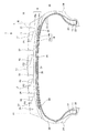
以下、本実施形態の空気入りタイヤについて説明する。図1は、本実施形態の空気入りタイヤ(以降、タイヤという)10の断面を示すタイヤ断面図である。
タイヤ10は、例えば、乗用車用タイヤである。乗用車用タイヤは、JATMA YEAR BOOK 2012(日本自動車タイヤ協会規格)のA章に定められるタイヤをいう。この他、B章に定められる小型トラック用タイヤおよびC章に定められるトラック及びバス用タイヤに適用することもできる。
以降で具体的に説明する各パターン要素の寸法の数値は、乗用車用タイヤにおける数値例であり、本発明である空気入リタイヤはこれらの数値例に限定されない。
Hereinafter, embodiments of the present invention will be described in detail with reference to the drawings.
(Whole tire description)
Hereinafter, the pneumatic tire of this embodiment will be described. FIG. 1 is a tire cross-sectional view showing a cross section of a pneumatic tire (hereinafter referred to as a tire) 10 of the present embodiment.
The
The numerical value of the dimension of each pattern element specifically explained below is a numerical example in the tire for passenger cars, and the pneumatic retirement according to the present invention is not limited to these numerical examples.
以降で説明するタイヤ周方向とは、タイヤ回転軸を中心にタイヤ10を回転させたとき、トレッド面の回転する方向(両回転方向)をいい、タイヤ径方向とは、タイヤ回転軸に対して直交して延びる放射方向をいい、タイヤ径方向外側とは、タイヤ回転軸からタイヤ径方向に離れる側をいう。タイヤ幅方向とは、タイヤ回転軸方向に平行な方向をいい、タイヤ幅方向外側とは、タイヤ10のタイヤセンターラインCLから離れる両側をいう。
The tire circumferential direction described below refers to the direction of rotation of the tread surface (both rotation directions) when the
(タイヤ構造)
タイヤ10は、骨格材として、一対のビードコア11と、カーカスプライ層12と、ベルト層14とを有し、これらの骨格材の周りに、トレッドゴム部材18と、サイドゴム部材20と、ビードフィラーゴム部材22と、リムクッションゴム部材24と、インナーライナゴム部材26と、を主に有する。
(Tire structure)
The
一対のビードコア11は円環状であり、タイヤ幅方向の両端部であって、タイヤ径方向内側端部に配置されている。
カーカスプライ層12は、有機繊維をゴムで被覆した1又は複数のカーカスプライ材12a、12bからなる。カーカスプライ材12a、12bは、一対のビードコア11の間に巻き回すことによりトロイダル形状に形成されている。
ベルト層14は複数のベルト材14a、14bからなり、カーカスプライ層12のタイヤ径方向外側にタイヤ周方向に巻き回されている。タイヤ径方向内側のベルト材14aのタイヤ幅方向の幅は、タイヤ径方向外側のベルト材14bの幅に比べて広い。
ベルト材14a、14bは、スチールコードにゴムを被覆した部材である。ベルト材14aのスチールコード、および、ベルト材14bのスチールコードは、タイヤ周方向に対して所定の角度、例えば20〜30度傾斜して配置されている。ベルト材14aのスチールコードと、ベルト材14bのスチールコードとは、タイヤ周方向に対して互いに逆方向に傾斜し、互いに交錯する。ベルト層14は充填された空気圧によるカーカスプライ層12の膨張を抑制する。
The pair of
The
The
The
ベルト層14のタイヤ径方向外側には、トレッドゴム部材18が設けられる。トレッドゴム部材18の両端部には、サイドゴム部材20が接続されている。トレッドゴム部材18は、タイヤ径方向外側に設けられる上層トレッドゴム部材18aと、タイヤ径方向内側に設けられる下層トレッドゴム部材18bとの2層のゴム部材からなる。サイドゴム部材20のタイヤ径方向内側の端には、リムクッションゴム部材24が設けられる。リムクッションゴム部材24はタイヤ10を装着するリムと接触する。ビードコア11のタイヤ径方向外側には、ビードコア11の周りに巻きまわしたカーカスプライ層12に挟まれるようにビードフィラーゴム部材22が設けられている。タイヤ10とリムとで囲まれる空気を充填するタイヤ空洞領域に面するタイヤ10の内表面には、インナーライナゴム部材26が設けられている。
この他に、タイヤ10は、ベルト層14のタイヤ径方向外側面を覆うベルトカバー層28を備える。ベルトカバー層28は、有機繊維と、この有機繊維を被覆するゴムとからなる。
A
In addition, the
タイヤ10は、図1に示すタイヤ構造を有するが、本発明の空気入りタイヤのタイヤ構造は、これに限定されない。
Although the
図2は空気入りタイヤ10のトレッドパターン30を示す展開図である。本発明のタイヤ10は、図2に示すように、トレッド部Tにトレッドパターン30が形成されている。トレッドパターン30を有するタイヤ10は、乗用車用タイヤに好適に用いることができる。ここでは、図2の右側が車両への装着時に車両の幅方向内側に配置される側、図2の左側が車両への装着時に車両の幅方向外側に配置される側である場合について説明する。
FIG. 2 is a development view showing the tread pattern 30 of the
本実施形態のタイヤ10は、タイヤ回転方向が予め定められており、車両の前進時に図2のタイヤ回転方向Rに回転するように、車両に装着される。タイヤ10のサイドゴム部材20の表面には、この回転移動の方向を指定する記号や情報(セリアル記号)が表示されている。本実施形態においては、図示しないが、図2の左側のサイドゴム部材20の表面にセリアル記号が設けられている。タイヤ10がタイヤ回転方向Rに回転するとき、トレッド部Tが図2の上から下に回転移動し、トレッド部Tの路面と接触する位置は図2の下から上に移動する。
図2において、符号CLはタイヤのセンターラインを示す。トレッドパターン30は、タイヤ10が車両に装着された状態で、接地端E1、E2の間で示すタイヤ幅方向領域において路面に接地する。
The
In FIG. 2, the symbol CL indicates the center line of the tire. The tread pattern 30 contacts the road surface in the tire width direction region indicated between the contact ends E1 and E2 in a state where the
ここで、接地端E1、E2の間隔が接地幅Wである。接地端E1、E2は、タイヤ10を規定リムに組み付け、規定内圧を充填し、規定荷重の80%を負荷荷重とした条件において水平面に接地させたときの接地面のタイヤ幅方向の両端部である。
Here, the distance between the grounding ends E1 and E2 is the grounding width W. The ground contact ends E1 and E2 are at both ends of the ground contact surface in the tire width direction when the
本実施形態においてタイヤ幅方向Wとは、タイヤ10の回転中心軸方向をいい、図1および図2の左右方向である。また、タイヤ周方向Cとはタイヤ10の回転方向Rおよびその反対方向をいい、図1の紙面に垂直な方向および図2の上下方向である。
In the present embodiment, the tire width direction W refers to the direction of the rotation center axis of the
トレッドパターン30は、複数の周方向主溝31、32、33、34、周方向副溝35、および、複数のラグ溝群と、を備える。
The tread pattern 30 includes a plurality of circumferential
第1周方向主溝31、第2周方向主溝32、第3周方向主溝33、第4周方向主溝34、および周方向副溝35は、タイヤ接地端E1側からタイヤ接地端E2側に向けてこの順に設けられている。
第1周方向主溝31、第2周方向主溝32、第3周方向主溝33、第4周方向主溝34、および周方向副溝35は、タイヤ周方向に延び、タイヤ全周にわたって環状に設けられている。本実施形態においては、第1周方向主溝31および第2周方向主溝32がタイヤセンターラインCLよりも接地端E1側に設けられ、第3周方向主溝33、第4周方向主溝34、および周方向副溝35がタイヤセンターラインCLよりも接地端E2側に設けられている。
The first circumferential
The first circumferential
第1ラグ溝群は、複数の第1ラグ溝41からなる。複数の第1ラグ溝41は第1周方向主溝31と第2周方向主溝32との間の領域L1において、タイヤ周方向に互いに離間して設けられている。
各第1ラグ溝41は、第1周方向主溝31および第2周方向主溝32から離間した位置を開始端とし、タイヤ回転方向Rと反対方向に向かうとともに、第1周方向主溝31側に向かって傾斜して第1周方向主溝31に開口している。このため、領域L1の陸部は、タイヤ周方向に連続している。
The first lug groove group includes a plurality of
Each of the
第2ラグ溝群は、複数の第2ラグ溝42からなる。複数の第2ラグ溝42は第2周方向主溝32と第3周方向主溝33との間の領域L2において、タイヤ周方向に互いに離間して設けられている。
各第2ラグ溝42は、第2周方向主溝32および第3周方向主溝33から離間した位置を開始端とし、タイヤ回転方向Rと反対方向に向かうとともに、第2周方向主溝32側に向かって傾斜して第2周方向主溝32に開口している。このため、領域L2の陸部は、タイヤ周方向に連続している。なお、本実施形態においては、各第2ラグ溝42の開始端はタイヤセンターラインCLよりも接地端E1側に設けられている。
The second lug groove group includes a plurality of
Each of the
第3ラグ溝群は、複数の第3ラグ溝43からなる。複数の第3ラグ溝43は第3周方向主溝33と第4周方向主溝34との間の領域L3において、タイヤ周方向に互いに離間して設けられている。
各第3ラグ溝43は、第3周方向主溝33および第4周方向主溝34から離間した位置を開始端とし、タイヤ回転方向Rと反対方向に向かうとともに、第3周方向主溝33側に向かって傾斜して第3周方向主溝33に開口している。このため、領域L3の陸部は、タイヤ周方向に連続している。
The third lug groove group includes a plurality of
Each of the
第4ラグ溝群は、複数の第4ラグ溝44からなる。複数の第4ラグ溝44は第4周方向主溝34と周方向副溝35との間の領域L4において、タイヤ周方向に互いに離間して設けられている。
各第4ラグ溝44は、第4周方向主溝34および周方向副溝35から離間した位置を開始端とし、タイヤ回転方向Rと反対方向に向かうとともに、第4周方向主溝34側に向かって傾斜して第4周方向主溝34に開口している。このため、領域L4の陸部は、タイヤ周方向に連続している。
The fourth lug groove group includes a plurality of
Each of the
ラグ溝群が設けられていることで、各領域L1〜L4における溝面積比が異なっている。本実施形態においては、領域L2の溝面積比が最も大きく、領域L1の溝面積比が領域L2の次に大きく、領域L3の溝面積比が領域L1の次に大きく、領域L4の溝面積比が領域L3の次に大きい。
ラグ溝群が設けられていると、各ラグ溝41〜44が接地前端近傍では各領域L1〜L4の陸部が路面に接地することでタイヤ幅方向およびタイヤ周方向の曲率が0になるように変形する。この変形量は各領域L1〜L4の溝面積比が大きいほど大きくなるため、各領域L1〜L4の溝面積比が異なると、接地形状が不均一になるおそれがある。接地後端においても同様である。
By providing the lug groove group, the groove area ratios in the regions L1 to L4 are different. In the present embodiment, the groove area ratio of the region L2 is the largest, the groove area ratio of the region L1 is next to the region L2, the groove area ratio of the region L3 is next to the region L1, and the groove area ratio of the region L4. Is next to the area L3.
When the lug groove group is provided, when the
本実施形態においては、各領域L1〜L4の溝面積比に応じて、溝面積比が大きい領域の陸部ほど踏面の基準輪郭線Bからの最大突出量を大きくしている。具体的には、溝面積比が大きい領域ほど、接地したときの変形量が大きくなるため、この変形量に応じて各領域L1〜L4の陸部の踏面を基準輪郭線Bから突出させている。各領域L1〜L4の溝面積比が大きいほど各領域L1〜L4の陸部の踏面を、図1に破線で示す基準輪郭線Bから大きく突出させることで、接地したときの変形量を相殺し、接地形状を均一にすることができる。
このため、操縦安定性および摩耗耐性を向上することができる。
本実施形態においては、各領域L1〜L4の陸部の踏面の基準輪郭線Bからの最大突出量をP1〜P4とすると、P2>P1>P3>P4となっている。なお、領域L4は最も溝面積が小さいため、領域L4の陸部の踏面の基準輪郭線Bからの突出量P4は0であってもよい。
In this embodiment, according to the groove area ratio of each area | region L1-L4, the maximum protrusion amount from the reference | standard outline B of a tread is enlarged as the land part of an area | region where a groove area ratio is large. Specifically, since the region with a larger groove area ratio has a larger deformation amount when grounded, the tread of the land portion of each of the regions L1 to L4 protrudes from the reference contour line B according to the deformation amount. . The larger the groove area ratio of each of the regions L1 to L4, the larger the tread of the land portion of each of the regions L1 to L4 protrudes from the reference contour line B indicated by a broken line in FIG. The grounding shape can be made uniform.
For this reason, steering stability and abrasion resistance can be improved.
In the present embodiment, P2>P1>P3> P4, where P1 to P4 are the maximum protrusion amounts from the reference contour line B of the tread surface of the land portion in each of the regions L1 to L4. In addition, since the area | region L4 has the smallest groove area, the protrusion amount P4 from the reference | standard outline B of the tread of the land part of the area | region L4 may be zero.
ここで、「基準輪郭線」とは、タイヤ径方向の断面において、対象となる陸部を区画する2本の周方向主溝の溝壁と踏面との4つの接続端に対してカーブフィッティング(曲線あてはめ)した円弧である。 Here, the “reference contour line” is a curve fitting (with respect to the four connecting ends of the groove wall and the tread surface of the two circumferential main grooves defining the target land portion in the tire radial cross section ( A curved arc).
ここで、「接続端」とは、周方向主溝の溝壁と陸部の踏面とにより形成される角部の頂点であり、周方向主溝の溝壁と陸部の踏面とにより形成される角部が面取りされている場合には、面取り面と陸部の踏面との交点である。
上記接続端の位置に対し、最小二乗法を用いて円弧状の回帰曲線を求め、これを基準輪郭線Bとすることができる。
Here, the “connection end” is the apex of the corner formed by the groove wall of the circumferential main groove and the tread of the land, and is formed by the groove wall of the circumferential main groove and the tread of the land. If the corner is chamfered, it is the intersection of the chamfered surface and the land tread.
With respect to the position of the connection end, an arc-shaped regression curve can be obtained using the least square method, and this can be used as the reference contour B.
各陸部の踏面の基準輪郭線Bからの最大突出量は、0.05mm〜2.00mmであることが好ましい。最大突出量が0.05mmよりも小さいと接地形状を改善する効果が充分に得られない。一方、最大突出量が2.00mmよりも大きいと各陸部のタイヤ幅方向の中央部での偏摩耗が生じる。 The maximum protrusion amount from the reference contour line B of the tread of each land portion is preferably 0.05 mm to 2.00 mm. If the maximum protrusion amount is smaller than 0.05 mm, the effect of improving the ground contact shape cannot be obtained sufficiently. On the other hand, when the maximum protrusion amount is larger than 2.00 mm, uneven wear occurs in the center portion of each land portion in the tire width direction.
各陸部の踏面の基準輪郭線Bからの突出形状は、タイヤ径方向の断面において、各陸部の両端を通る任意の2次曲線形状(例えば、円弧、放物線、双曲線等)であってもよい。各領域L1〜L4の溝面積比が大きいほど、タイヤ径方向の断面における陸部の踏面と基準輪郭線Bとで囲まれる領域の面積を大きくすることで、ラグ溝によるトレッドゴムの減少量を補い、陸部の剛性の低下を相殺することができる。 The protruding shape from the reference contour line B of the tread of each land portion may be an arbitrary quadratic curve shape (for example, an arc, a parabola, a hyperbola, etc.) passing through both ends of each land portion in the tire radial cross section. Good. As the groove area ratio of each of the regions L1 to L4 is larger, the area of the region surrounded by the tread surface of the land portion and the reference contour line B in the cross section in the tire radial direction is increased, thereby reducing the amount of tread rubber reduction due to the lug groove. It is possible to compensate for the decrease in rigidity of the land portion.
溝面積比が大きい領域の陸部ほど踏面の基準輪郭線Bからの突出量を大きくする例として、例えば、溝面積比が0%以上5%未満のとき、踏面の基準輪郭線Bからの突出量を0.05mm以上0.15mm未満とし、溝面積比が5%以上10%以下のとき、踏面の基準輪郭線Bからの突出量を0.15mm以上0.25mm以下とすることができる。このように突出量を設定することで、周方向主溝を除く溝面積比が10%以下であるタイヤにおいて、偏摩耗を抑制することができる。 As an example of increasing the amount of protrusion from the reference contour line B of the tread as the land portion of the region where the groove area ratio is large, for example, when the groove area ratio is 0% or more and less than 5%, the protrusion of the tread from the reference contour B When the amount is 0.05 mm or more and less than 0.15 mm and the groove area ratio is 5% or more and 10% or less, the protruding amount of the tread from the reference contour line B can be 0.15 mm or more and 0.25 mm or less. By setting the protruding amount in this way, uneven wear can be suppressed in a tire having a groove area ratio excluding the circumferential main groove of 10% or less.
[実験例]
本発明のタイヤ10の効果を調べるために、以下の表1、表2に示す仕様のトレッドパターンを設けたタイヤを作製し、タイヤ性能を評価した。
[Experimental example]
In order to examine the effects of the
タイヤサイズは、215/60R17 96Hとした。
従来例、比較例、参考例1〜8、実施例1,2のタイヤでは、図2に示すのと同様のトレッドパターンを有するタイヤを使用した。各領域L1〜L3における溝面積比および突出量P1〜P3はそれぞれ表1、表2に示すとおりである。なお、領域L4における突出量P4は、いずれも0mmとした。
The tire size was 215 / 60R17 96H.
In the tires of the conventional examples, comparative examples, reference examples 1 to 8, and examples 1 and 2 , tires having a tread pattern similar to that shown in FIG. 2 were used. The groove area ratios and the protrusion amounts P1 to P3 in the regions L1 to L3 are as shown in Tables 1 and 2, respectively. Note that the protrusion amount P4 in the region L4 is 0 mm.
以上の試作したタイヤのタイヤ性能として、操縦安定性および偏摩耗について、下記のようにして評価した。 As the tire performance of the prototype tire described above, steering stability and uneven wear were evaluated as follows.
〔操縦安定性〕
上記タイヤを装着した乗用車で試験コースを走行してドライバーによる操縦安定性能の官能評価を行った。タイヤ空気圧は240kPaとした。従来例のタイヤでの評価を基準値(100)とする指数で評価し、指数が高いほど操縦安定性が優れると評価した。
[Maneuvering stability]
A passenger car equipped with the above tires was run on a test course, and the driver's steering stability performance was evaluated. The tire pressure was 240 kPa. The evaluation with the tire of the conventional example was evaluated with an index with the reference value (100), and the higher the index, the better the steering stability.
〔偏摩耗〕
新品タイヤを装着した車両で試験コースを10000km走行した後、第2周方向主溝32と第3周方向主溝33との間の領域のタイヤ幅方向の中央部と両端部の摩耗量の差を求めた。従来例のタイヤでの摩耗量の逆数を基準値(100)とする指数で評価し、指数が高いほど偏摩耗性能が優れると評価した。
[Uneven wear]
After running the test course for 10,000 km on a vehicle equipped with a new tire, the difference in the amount of wear between the center portion and both end portions in the tire width direction in the region between the second circumferential
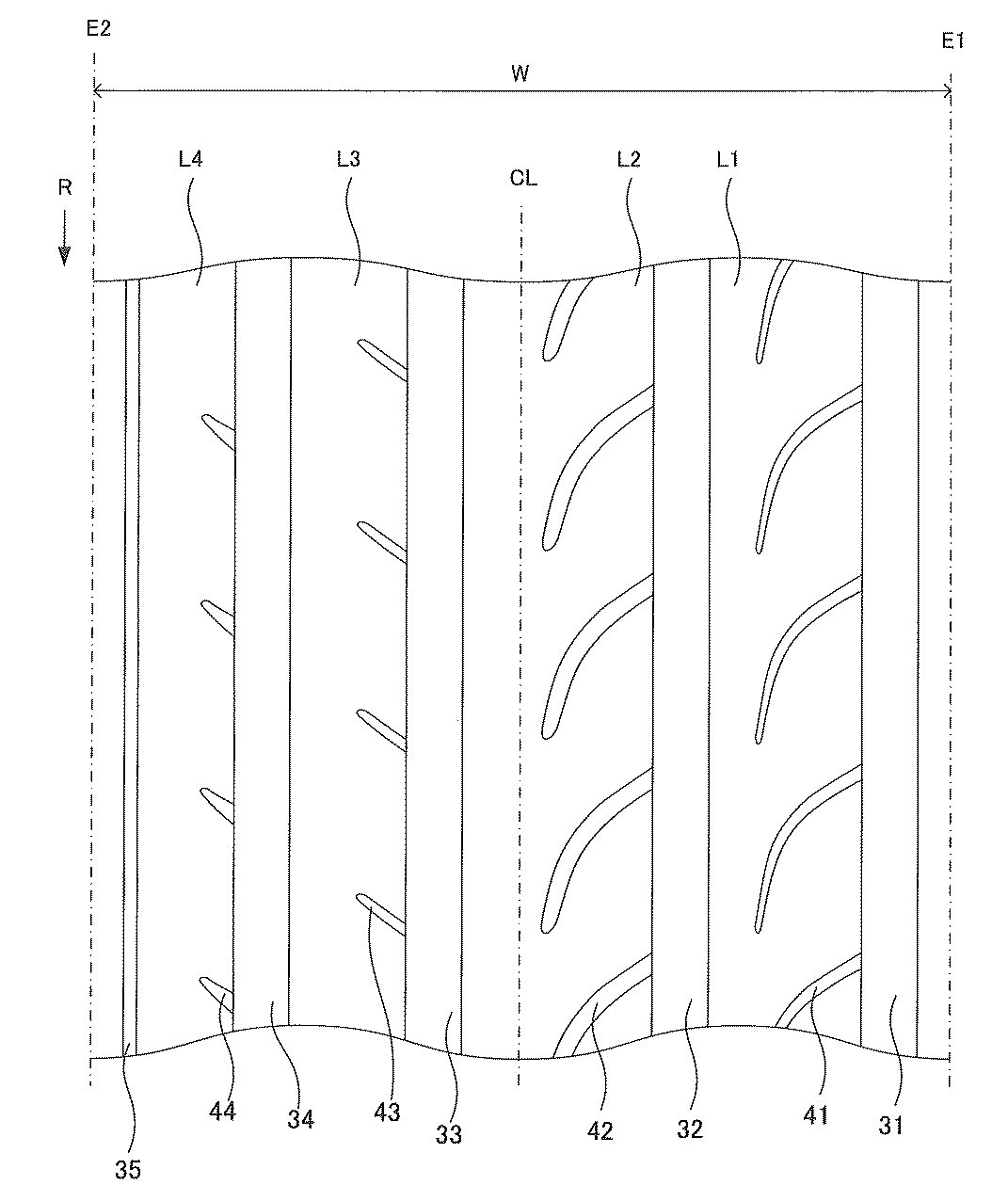
表2の参考例5〜8と実施例1,2とを比較すると、溝面積比が0%以上5%未満のときの突出量を0.05mm以上0.15mm未満とし、溝面積比が5%以上10%以下のときの突出量を0.15mm以上0.25mm以下とすることで、操縦安定性および偏摩耗性能がさらに高まることがわかる。 Comparing Reference Examples 5 to 8 in Table 2 with Examples 1 and 2 , the protrusion amount when the groove area ratio is 0% or more and less than 5% is 0.05 mm or more and less than 0.15 mm, and the groove area ratio is 5 It can be seen that the steering stability and the uneven wear performance are further improved by setting the protrusion amount when the ratio is not less than 10% and not more than 10% to be not less than 0.15 mm and not more than 0.25 mm.
以上、本発明の空気入りタイヤについて詳細に説明したが、本発明は上記実施形態に限定されず、本発明の主旨を逸脱しない範囲において、種々の改良や変更をしてもよいのはもちろんである。 As mentioned above, although the pneumatic tire of this invention was demonstrated in detail, this invention is not limited to the said embodiment, Of course, in the range which does not deviate from the main point of this invention, you may make a various improvement and change. is there.
CL センターライン
E1、E2 接地端
T トレッド部
30 トレッドパターン
31 第1周方向主溝
32 第2周方向主溝
33 第3周方向主溝
34 第4周方向主溝
35 周方向副溝
41 第1ラグ溝
42 第2ラグ溝
43 第3ラグ溝
44 第4ラグ溝
CL center line E1, E2 Grounding end T tread portion 30
Claims (1)
前記トレッド部は、
タイヤ幅方向にタイヤ周方向に延び、溝幅の異なる3本以上の周方向主溝によって区画される複数の領域を有し、
前記各領域は異なる溝面積比を有し、
前記各領域の陸部の踏面は前記トレッド部の基準輪郭線に対してタイヤ径方向外側に突出しており、
前記領域のうち、前記溝面積比が0%以上5%未満の領域では、踏面の前記基準輪郭線からの突出量は0.05mm以上0.15mm未満であり、
前記溝面積比が5%以上10%以下の領域では、踏面の前記基準輪郭線からの突出量は0.15mm以上0.25mm以下であることを特徴とする空気入りタイヤ。 A pneumatic tire having a tread portion provided with a tread pattern,
The tread portion is
A plurality of regions extending in the tire circumferential direction in the tire width direction and defined by three or more circumferential main grooves having different groove widths;
Each region has a different groove area ratio;
The tread of the land portion of each region protrudes outward in the tire radial direction with respect to the reference contour line of the tread portion,
In the region where the groove area ratio is 0% or more and less than 5%, the protrusion amount of the tread from the reference contour line is 0.05 mm or more and less than 0.15 mm,
In the region where the groove area ratio is 5% or more and 10% or less, the amount of protrusion of the tread surface from the reference contour line is 0.15 mm or more and 0.25 mm or less .
Priority Applications (1)
| Application Number | Priority Date | Filing Date | Title |
|---|---|---|---|
| JP2014244720A JP6439416B2 (en) | 2014-12-03 | 2014-12-03 | Pneumatic tire |
Applications Claiming Priority (1)
| Application Number | Priority Date | Filing Date | Title |
|---|---|---|---|
| JP2014244720A JP6439416B2 (en) | 2014-12-03 | 2014-12-03 | Pneumatic tire |
Publications (2)
| Publication Number | Publication Date |
|---|---|
| JP2016107693A JP2016107693A (en) | 2016-06-20 |
| JP6439416B2 true JP6439416B2 (en) | 2018-12-19 |
Family
ID=56122987
Family Applications (1)
| Application Number | Title | Priority Date | Filing Date |
|---|---|---|---|
| JP2014244720A Active JP6439416B2 (en) | 2014-12-03 | 2014-12-03 | Pneumatic tire |
Country Status (1)
| Country | Link |
|---|---|
| JP (1) | JP6439416B2 (en) |
Families Citing this family (3)
| Publication number | Priority date | Publication date | Assignee | Title |
|---|---|---|---|---|
| JP6819213B2 (en) * | 2016-10-26 | 2021-01-27 | 住友ゴム工業株式会社 | Pneumatic tires |
| JP6819212B2 (en) * | 2016-10-26 | 2021-01-27 | 住友ゴム工業株式会社 | Pneumatic tires |
| JP7013765B2 (en) * | 2017-09-22 | 2022-02-15 | 横浜ゴム株式会社 | Pneumatic tires |
Family Cites Families (10)
| Publication number | Priority date | Publication date | Assignee | Title |
|---|---|---|---|---|
| JPH0616106U (en) * | 1992-07-23 | 1994-03-01 | オーツタイヤ株式会社 | Tire tread structure |
| JP4102151B2 (en) * | 2002-10-01 | 2008-06-18 | 住友ゴム工業株式会社 | Pneumatic tire |
| JP2005132305A (en) * | 2003-10-31 | 2005-05-26 | Bridgestone Corp | Pneumatic tire |
| WO2006033383A1 (en) * | 2004-09-24 | 2006-03-30 | Bridgestone Corporation | Pneumatic tire |
| JP4406455B2 (en) * | 2007-12-18 | 2010-01-27 | 住友ゴム工業株式会社 | Pneumatic tire |
| JP4973708B2 (en) * | 2009-09-11 | 2012-07-11 | 横浜ゴム株式会社 | Pneumatic tire |
| JP4826681B1 (en) * | 2010-11-17 | 2011-11-30 | 横浜ゴム株式会社 | Pneumatic tire |
| JP5387707B2 (en) * | 2012-03-14 | 2014-01-15 | 横浜ゴム株式会社 | Pneumatic tire |
| EP2960079B1 (en) * | 2013-02-25 | 2018-01-10 | The Yokohama Rubber Co., Ltd. | Pneumatic tire |
| JP6433760B2 (en) * | 2014-10-31 | 2018-12-05 | 東洋ゴム工業株式会社 | Pneumatic tire |
-
2014
- 2014-12-03 JP JP2014244720A patent/JP6439416B2/en active Active
Also Published As
| Publication number | Publication date |
|---|---|
| JP2016107693A (en) | 2016-06-20 |
Similar Documents
| Publication | Publication Date | Title |
|---|---|---|
| JP5146564B2 (en) | Pneumatic tire | |
| JP5790876B2 (en) | Pneumatic tire | |
| JP5333510B2 (en) | Pneumatic tire | |
| JP5062344B1 (en) | Pneumatic tire | |
| WO2015163157A1 (en) | Pneumatic tire | |
| JP5780318B2 (en) | Pneumatic tire | |
| JP6551506B2 (en) | Pneumatic tire | |
| JP6439416B2 (en) | Pneumatic tire | |
| JP2010036598A (en) | Pneumatic tire | |
| JP2017013693A (en) | Pneumatic tire and design method therefor | |
| JP6421652B2 (en) | Pneumatic tire | |
| JP2017132279A (en) | Pneumatic tire and design method for pneumatic tire | |
| WO2016093069A1 (en) | Pneumatic tire | |
| JP6364783B2 (en) | Pneumatic tire | |
| JP2017013663A (en) | Pneumatic tire and design method for pneumatic tire | |
| JP6657707B2 (en) | Pneumatic tire | |
| JP6060217B2 (en) | Pneumatic tires for motorcycles | |
| JP7207304B2 (en) | pneumatic tire | |
| JP7013765B2 (en) | Pneumatic tires | |
| JP6790841B2 (en) | Pneumatic tires | |
| JP2016088407A (en) | Pneumatic tire | |
| JP7251185B2 (en) | pneumatic tire | |
| JP2013216256A (en) | Pneumatic tire | |
| JP7189800B2 (en) | pneumatic tire | |
| CN112368159B (en) | Pneumatic tire |
Legal Events
| Date | Code | Title | Description |
|---|---|---|---|
| A621 | Written request for application examination |
Free format text: JAPANESE INTERMEDIATE CODE: A621 Effective date: 20171204 |
|
| A871 | Explanation of circumstances concerning accelerated examination |
Free format text: JAPANESE INTERMEDIATE CODE: A871 Effective date: 20180525 |
|
| A975 | Report on accelerated examination |
Free format text: JAPANESE INTERMEDIATE CODE: A971005 Effective date: 20180614 |
|
| A131 | Notification of reasons for refusal |
Free format text: JAPANESE INTERMEDIATE CODE: A131 Effective date: 20180619 |
|
| A977 | Report on retrieval |
Free format text: JAPANESE INTERMEDIATE CODE: A971007 Effective date: 20180620 |
|
| A521 | Request for written amendment filed |
Free format text: JAPANESE INTERMEDIATE CODE: A523 Effective date: 20180820 |
|
| TRDD | Decision of grant or rejection written | ||
| A01 | Written decision to grant a patent or to grant a registration (utility model) |
Free format text: JAPANESE INTERMEDIATE CODE: A01 Effective date: 20181023 |
|
| A61 | First payment of annual fees (during grant procedure) |
Free format text: JAPANESE INTERMEDIATE CODE: A61 Effective date: 20181105 |
|
| R150 | Certificate of patent or registration of utility model |
Ref document number: 6439416 Country of ref document: JP Free format text: JAPANESE INTERMEDIATE CODE: R150 |
|
| R250 | Receipt of annual fees |
Free format text: JAPANESE INTERMEDIATE CODE: R250 |
|
| R250 | Receipt of annual fees |
Free format text: JAPANESE INTERMEDIATE CODE: R250 |
|
| S531 | Written request for registration of change of domicile |
Free format text: JAPANESE INTERMEDIATE CODE: R313531 |
|
| R350 | Written notification of registration of transfer |
Free format text: JAPANESE INTERMEDIATE CODE: R350 |
|
| R250 | Receipt of annual fees |
Free format text: JAPANESE INTERMEDIATE CODE: R250 |