JP6438687B2 - Radio wave absorber and manufacturing method thereof - Google Patents
Radio wave absorber and manufacturing method thereof Download PDFInfo
- Publication number
- JP6438687B2 JP6438687B2 JP2014124348A JP2014124348A JP6438687B2 JP 6438687 B2 JP6438687 B2 JP 6438687B2 JP 2014124348 A JP2014124348 A JP 2014124348A JP 2014124348 A JP2014124348 A JP 2014124348A JP 6438687 B2 JP6438687 B2 JP 6438687B2
- Authority
- JP
- Japan
- Prior art keywords
- layer
- fiber
- surface layer
- monofilament
- fineness
- Prior art date
- Legal status (The legal status is an assumption and is not a legal conclusion. Google has not performed a legal analysis and makes no representation as to the accuracy of the status listed.)
- Active
Links
Images


Description
本発明は、電波吸収体及びその製造方法に関する。 The present invention relates to a radio wave absorber and a manufacturing method thereof.
通信障害対策やノイズ対策のために電波吸収体を用いることが知られている。かかる電波吸収体として、例えば、特許文献1及び2には、カーボンを含む導電被膜で被覆されたポリ塩化ビニリデン繊維が絡まってマット状に形成され、表面側に太い繊維が配される一方、裏面側に細い繊維が配され、それによって厚さ方向に繊維密度が変化した電波吸収体が開示されている。 It is known to use a radio wave absorber for countermeasures against communication failure and noise. As such a radio wave absorber, for example, in Patent Documents 1 and 2, a polyvinylidene chloride fiber coated with a conductive film containing carbon is entangled and formed into a mat shape, and thick fibers are arranged on the front side, while the back side There is disclosed a radio wave absorber in which fine fibers are arranged on the side and thereby the fiber density is changed in the thickness direction.
近年、前方障害物の検出や前車追従のための車載レーダーがフロントバンパーに設けられた自動車が実用化されている。このような車載レーダーが設けられた自動車は、安全面や利便面から、今後益々増えていくことが予想される。 In recent years, an automobile in which an in-vehicle radar for detecting a front obstacle and following a front vehicle is provided on a front bumper has been put into practical use. The number of vehicles equipped with such on-vehicle radars is expected to increase in the future from the viewpoint of safety and convenience.
ところで、車載レーダーの評価では高精度の試験が必要であり、実際に車載レーダーを搭載した自動車の走行試験を行う場合、車載レーダーからの電波の乱反射を防止するため、周辺の構造物に優れた電波吸収性能を示す電波吸収体を設置する必要がある。 By the way, evaluation of in-vehicle radars requires high-precision tests. When actually running a car equipped with in-vehicle radars, it is superior in surrounding structures to prevent irregular reflection of radio waves from in-vehicle radars. It is necessary to install a radio wave absorber that exhibits radio wave absorption performance.
通常、車載レーダーではミリ波、特にWバンド(75〜110GHz)の電波を使用することが多いが、かかるWバンドの電波に対して優れた電波吸収性能を示す電波吸収体としては、電波暗室等に用いられるピラミッド型の電波吸収体が挙げられる。しかしながら、ピラミッド型の電波吸収体は、そもそも室内用であるために屋外での使用が難しいことに加え、試験の度に屋外に設置する必要があることから、欠けや割れ等が生じることがないように取り扱いに注意を払う必要がある。また、特許文献1及び2に開示された電波吸収体は、屋外用途には適しているものの、Wバンドの電波に対して電波吸収性能が十分であるとは言えない。 Usually, in-vehicle radars often use millimeter waves, particularly W-band (75 to 110 GHz) radio waves, and examples of radio wave absorbers that exhibit excellent radio wave absorption performance for such W-band radio waves include anechoic chambers. The pyramid type electromagnetic wave absorber used for the above is mentioned. However, since pyramid-type wave absorbers are used indoors in the first place, they are difficult to use outdoors, and they need to be installed outdoors every time they are tested, so there is no chipping or cracking. It is necessary to pay attention to handling. In addition, although the radio wave absorbers disclosed in Patent Documents 1 and 2 are suitable for outdoor use, it cannot be said that the radio wave absorption performance is sufficient for W-band radio waves.
本発明は、屋外用途に適していると共に、Wバンドの電波に対して優れた電波吸収性能を示す電波吸収体を提供することである。 The present invention is to provide a radio wave absorber that is suitable for outdoor use and that exhibits excellent radio wave absorption performance with respect to radio waves in the W band.
本発明は、モノフィラメントの繊度が3300〜11000dtexである繊維で構成された表面層と、モノフィラメントの繊度が17〜170dtexである繊維で構成された裏面層とを含み、前記表面層及び前記裏面層を構成する繊維が接着被膜を介して結合して不織布状のマットに形成され、且つ前記不織布状のマットを構成する繊維の表面が導電被膜で被覆された電波吸収体であって、前記表面層の表面が非圧縮加工面である。 The present invention includes a surface layer composed of fibers having a monofilament fineness of 3300 to 11000 dtex and a back surface layer composed of fibers having a monofilament fineness of 17 to 170 dtex. An electromagnetic wave absorber in which the constituent fibers are bonded to each other through an adhesive coating to form a nonwoven mat , and the surface of the fibers constituting the nonwoven mat is covered with a conductive coating, The surface is an uncompressed surface.
本発明は、裏面層を構成するためのモノフィラメントの繊度が17〜170dtexである繊維を散布して繊維層を形成する裏面層形成ステップと、前記裏面層形成ステップで形成した繊維層の上に、表面層を構成するためのモノフィラメントの繊度が3300〜11000dtexである繊維を散布して積層する表面層形成ステップと、前記裏面層形成ステップ及び前記表面層形成ステップで積層して形成した繊維層の上から接着剤を散布し、繊維層を構成する繊維を接着被膜を介して結合させて不織布状のマットを形成する接着ステップと、前記接着ステップで形成した不織布状のマットの上から導電塗料を噴霧散布して乾燥させることにより、前記不織布状のマットを構成する繊維の表面を導電被膜で被覆する導電性付与ステップとを有する電波吸収体の製造方法であって、表面層の表面を平坦面で圧する圧縮加工を行わないものである。 The present invention, on the back layer forming step of forming a fiber layer by spraying fibers having a monofilament fineness of 17 to 170 dtex for constituting the back layer, on the fiber layer formed in the back layer forming step, A surface layer forming step of spreading and laminating fibers having a monofilament fineness of 3300 to 11000 dtex for constituting the surface layer; and a fiber layer formed by laminating in the back layer forming step and the surface layer forming step. An adhesive step is applied to form a nonwoven fabric mat by bonding the fibers constituting the fiber layer through an adhesive coating, and a conductive paint is sprayed from the nonwoven fabric mat formed in the adhesion step. by spraying to dry, and a conductivity-imparting step of coating the surface of the fibers constituting the nonwoven mat with a conductive coating A method for producing a radio wave absorber, a is not conducted compression process which applies the surface of the surface layer at the flat surface.
本発明によれば、表面層及び裏面層を構成する繊維が接着被膜を介して結合して不織布状のマットに形成された簡単な構造であるので、取り扱いが容易であって屋外用途に好適に用いることができる。また、モノフィラメントの繊度が3300〜11000dtexである繊維で構成された表面層の表面が非圧縮加工面であるので、表面層の繊維密度が疎であると共に、繊維が起毛した凹凸を有する表面に構成され、そのため、波長の短いWバンドの入射波は電波吸収体内部に入り易く、その電波吸収体内部に入った入射波は反射を繰り返して減衰することから、Wバンドの電波に対して優れた電波吸収性能を得ることができる。 According to the present invention, since the fibers constituting the front surface layer and the back surface layer are bonded to each other through an adhesive coating and formed into a non-woven mat, it is easy to handle and suitable for outdoor use. Can be used. Further, since the surface of the surface layer composed of fibers having a monofilament fineness of 3300 to 11000 dtex is an uncompressed surface, the surface layer has a sparse fiber density and a surface having irregularities with raised fibers. Therefore, an incident wave in the W band having a short wavelength easily enters the inside of the radio wave absorber, and the incident wave that enters the inside of the radio wave absorber is repeatedly reflected and attenuated. Radio wave absorption performance can be obtained.
以下、実施形態について詳細に説明する。 Hereinafter, embodiments will be described in detail.
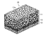
図1及び2は、実施形態に係る電波吸収体10を示す。実施形態に係る電波吸収体10は、例えば、屋外において、車載レーダーを搭載した自動車の走行試験を行う際に、車載レーダーからの電波の乱反射の防止を目的として周辺の構造物に設置されるものである。 1 and 2 show a radio wave absorber 10 according to an embodiment. The radio wave absorber 10 according to the embodiment is installed in a surrounding structure for the purpose of preventing irregular reflection of radio waves from the in-vehicle radar, for example, when performing a running test of an automobile equipped with the in-vehicle radar outdoors. It is.
実施形態に係る電波吸収体10は、モノフィラメントの繊度が相互に異なる繊維で構成された表面層11及び裏面層12並びにそれらの表面層11と裏面層12との間に設けられた中間層13を含む積層構造を有し、それらの表面層11、裏面層12、及び中間層13を構成する繊維が接着被膜を介して結合して不織布状のマットに形成されている。具体的には、表面層11、裏面層12、及び中間層13の各層内及び層間において、モノフィラメント同士が点接触乃至線接着して接着被膜により結合して一体化している。また、表面層11、裏面層12、及び中間層13を構成する繊維の表面が導電被膜で被覆されている。
The radio wave absorber 10 according to the embodiment includes a
実施形態に係る電波吸収体10では、表面層11を構成する繊維のモノフィラメントの繊度が3300〜11000dtex、及び裏面層12を構成する繊維のモノフィラメントの繊度が17〜170dtexである。中間層13を構成する繊維のモノフィラメントの繊度は、表面層11を構成する繊維のモノフィラメントの繊度と裏面層12を構成する繊維のモノフィラメントの繊度との中間であり、従って、裏面層12、中間層13、及び表面層11の順に繊維密度が低くなっている。また、実施形態に係る電波吸収体10では、表面層11の表面11aが非圧縮加工面とされている。なお、表面層11と中間層13との層間は、必ずしも明確でなくてもよく、表面層11を構成する繊維と中間層13を構成する繊維とが混在した層が形成されていてもよい。同様に、裏面層12と中間層13との層間も、必ずしも明確でなくてもよく、裏面層12を構成する繊維と中間層13を構成する繊維とが混在した層が形成されていてもよい。更には、表面層11、中間層13、及び裏面層12の層間が必ずしも明確でなく電波吸収体10全体として、その厚さ方向の表面側から裏面側に向かって繊度が漸次小さくなるように繊維が分布している構成であってもよい。
In the radio wave absorber 10 according to the embodiment, the fineness of the monofilament of the fiber constituting the
このような実施形態に係る電波吸収体10によれば、表面層11、裏面層12、及び中間層13を構成する繊維が接着被膜を介して結合して不織布状のマットに形成された簡単な構造であるので、取り扱いが容易であって屋外用途に好適に用いることができる。
According to the radio wave absorber 10 according to such an embodiment, the fibers constituting the
また、モノフィラメントの繊度が3300〜11000dtexである繊維で構成された表面層11の表面11aが非圧縮加工面であるので、表面層11の繊維密度が疎であると共に、繊維が起毛した凹凸を有する表面に構成され、そのため、波長の短いWバンド(75〜110GHz)の入射波は電波吸収体10内部に入り易く、その電波吸収体10内部に入った入射波は反射を繰り返して減衰することから、特にWバンドの電波に対して優れた電波吸収性能を得ることができる。
Moreover, since the
さらに、表面層11及び裏面層12を構成する繊維の太さの差が大きいものの、表面層11と裏面層12との間に、それらを構成する繊維の中間の太さの繊維で構成された中間層13が設けられていることにより、面内における厚さ方向の繊維密度勾配の均一化を図ることができる。
Furthermore, although the difference of the thickness of the fiber which comprises the
ここで、表面層11、裏面層12、及び中間層13を構成する繊維としては、例えば、ポリ塩化ビニリデン繊維、ナイロン繊維、ポリエステル繊維、アクリル繊維等が挙げられる。これらのうち耐候性が優れるという観点から、ポリ塩化ビニリデン繊維が好ましい。表面層11、裏面層12、及び中間層13を構成する繊維は同一種であることが好ましい。表面層11、裏面層12、及び中間層13を構成する繊維は、各層を嵩高くして電波を入射しやすくすることにより電波吸収性能を高める観点から、スプリング状にカール加工が施されたステープルファイバであることが好ましい。
Here, as a fiber which comprises the
表面層11を構成する繊維のモノフィラメントの繊度は、Wバンドの電波に対する電波吸収性能を高める観点から、好ましくは4000dtex以上であり、また、好ましくは4500dtex以下である。表面層11を構成する繊維のモノフィラメントの直径は例えば0.50〜0.70mmである。表面層11を構成する繊維のモノフィラメントの繊維長(カット長)は、好ましくは100mm以上、より好ましくは125mm以上であり、また、好ましくは200mm以下、より好ましくは175mm以下である。
The fineness of the monofilament of the fibers constituting the
裏面層12を構成する繊維のモノフィラメントの繊度は、好ましくは33dtex以上であり、また、好ましくは130dtex以下である。裏面層12を構成する繊維のモノフィラメントの繊度に対して、表面層11を構成する繊維のモノフィラメントの繊度は、Wバンドの電波に対する電波吸収性能を高める観点から、好ましくは20倍以上、より好ましくは50倍以上であり、また、好ましくは650倍以下、より好ましくは70倍以下、更に好ましくは60倍以下である。裏面層12を構成する繊維のモノフィラメントの直径は例えば0.04〜0.11mmである。
The fineness of the monofilament of the fibers constituting the
裏面層12を構成する繊維のモノフィラメントの繊維長(カット長)は、好ましくは30mm以上、より好ましくは50mm以上であり、また、好ましくは150mm以下、より好ましくは100mm以下である。裏面層12を構成する繊維のモノフィラメントの繊維長(カット長)は、表面層11を構成する繊維のモノフィラメントの繊維長(カット長)よりも短いことが好ましい。
The fiber length (cut length) of the monofilament of the fibers constituting the
中間層13を構成する繊維のモノフィラメントの繊度は、好ましくは170dtex以上であり、また、好ましくは1200dtex以下である。中間層13を構成する繊維のモノフィラメントの繊度に対して、表面層11を構成する繊維のモノフィラメントの繊度は、好ましくは4倍以上、より好ましくは6倍以上であり、また、好ましくは70倍以下、より好ましくは10倍以下である。裏面層12を構成する繊維のモノフィラメントの繊度に対して、中間層13を構成する繊維のモノフィラメントの繊度は、好ましくは5倍以上、より好ましくは8倍以上であり、また、好ましくは10倍以下、より好ましくは9倍以下である。中間層13を構成する繊維のモノフィラメントの繊度は、裏面層12を構成する繊維のモノフィラメントの繊度よりも、表面層11を構成する繊維のモノフィラメントの繊度に近いことが好ましい。中間層13を構成する繊維のモノフィラメントの直径は例えば0.10〜0.30mmである。
The fineness of the monofilament of the fibers constituting the
中間層13を構成する繊維のモノフィラメントの繊維長(カット長)は、好ましくは30mm以上、より好ましくは50mm以上であり、また、好ましくは150mm以下、より好ましくは100mm以下である。中間層13を構成する繊維のモノフィラメントの繊維長(カット長)は、裏面層12を構成する繊維のモノフィラメントの繊維長(カット長)よりも、表面層11を構成する繊維のモノフィラメントの繊維長(カット長)に近いことが好ましい。中間層13を構成する繊維のモノフィラメントの繊維長(カット長)は、表面層11を構成する繊維のモノフィラメントの繊維長(カット長)と同一であってもよい。
The fiber length (cut length) of the monofilament of the fibers constituting the
実施形態に係る電波吸収体10では、繊維全体における表面層11を構成する繊維の含有量は、Wバンドの電波に対する電波吸収性能を高める観点から、好ましくは60質量%以上、より好ましくは65質量%以上であり、また、好ましくは80質量%以下、より好ましくは75質量%以下である。繊維全体における裏面層12を構成する繊維の含有量は、好ましくは5質量%以上、より好ましくは10質量%以上であり、また、好ましくは25質量%以下、より好ましくは20質量%以下である。繊維全体における中間層13を構成する繊維の含有量は、好ましくは5質量%以上、より好ましくは10質量%以上であり、また、好ましくは25質量%以下、より好ましくは20質量%以下である。繊維全体における裏面層12を構成する繊維の含有量と繊維全体における中間層13を構成する繊維の含有量とは同一であってもよい。
In the
実施形態に係る電波吸収体10では、表面層11の表面11aが凹凸を有する非圧縮加工面であるため厚さが均一ではないが、表面層11の最も突出した部分における最大厚さは例えば35〜55mmである。また、実施形態に係る電波吸収体10では、表面層11の表面11aが凹凸を有する非圧縮加工面であるため、表面が圧縮加工により平坦面とされた場合と比較して圧縮変形に対する反力が低いが、Wバンドの電波に対する電波吸収性能を高める観点から、具体的には、65mm角の試験片を100mm/minの速度で30mm圧縮したときの反力が400N以下であることが好ましく、300N以下であることがより好ましい。なお、表面が圧縮加工により平坦面とされた電波吸収体10の場合、その反力は500Nを超える。
In the
接着被膜は、例えばゴムラテックス系接着剤が固化したもので構成されている。かかるゴムラテックス系接着剤としては、例えば、ポリ塩化ビニリデンゴムラテックスの接着剤が挙げられる。接着被膜の厚さは例えば5〜50μmである。 The adhesive coating is composed of, for example, a solidified rubber latex adhesive. Examples of such rubber latex adhesives include polyvinylidene chloride rubber latex adhesives. The thickness of the adhesive coating is, for example, 5 to 50 μm.
導電被膜は、例えば導電材料を含む導電塗料が固化したもので構成されている。かかる導電塗料としては、例えば、ポリ塩化ビニリデンゴムラテックスの接着剤にカーボンが分散したものが挙げられる。導電被膜の厚さは例えば5〜50μmである。 The conductive film is made of, for example, a solidified conductive paint containing a conductive material. An example of such a conductive paint is one in which carbon is dispersed in an adhesive of polyvinylidene chloride rubber latex. The thickness of the conductive film is, for example, 5 to 50 μm.
以上の構成の実施形態に係る電波吸収体10は、Wバンドにおける反射減衰量が好ましくは30dB以上である。
The
次に、実施形態に係る電波吸収体10の製造方法について説明する。
Next, a method for manufacturing the
まず、図3(a)に示すように、平坦な基台B上に、裏面層12を構成するためのモノフィラメントの繊度が17〜170dtexである繊維f1をランダムに散布する。このとき、基台B上には裏面層12を構成するための繊維f1の繊維層Fが形成される(裏面層形成ステップ)。
First, as shown in FIG. 3 (a), on a flat base B, the fineness of the monofilament for forming the
次いで、図3(b)に示すように、裏面層形成ステップで形成した繊維層Fの上に、中間層13を構成するための、モノフィラメントの繊度が、表面層11を構成する繊維のモノフィラメントの繊度と裏面層12を構成する繊維のモノフィラメントの繊度との中間である繊維f2をランダムに散布する。このとき、繊維層Fに中間層13を構成するための繊維f2が積層される(中間層形成ステップ)。
Next, as shown in FIG. 3B, the fineness of the monofilament for constituting the
続いて、図3(c)に示すように、裏面層形成ステップ及び中間層形成ステップで積層した繊維層Fの上に、表面層11を構成するためのモノフィラメントの繊度が3300〜11000dtexである繊維f3をランダムに散布する。このとき、繊維層Fに表面層11を構成するための繊維f3が積層される(表面層形成ステップ)。
Subsequently, as shown in FIG. 3 (c), a fiber having a fineness of monofilament for forming the
そして、図3(d)に示すように、裏面層形成ステップ、中間層形成ステップ、及び表面層形成ステップで積層して形成した繊維層Fの上から接着剤Aを噴霧散布して乾燥させる。このとき、繊維層Fを構成する繊維が接着被膜を介して結合して不織布状のマットMが形成される(接着ステップ)。 And as shown in FIG.3 (d), the adhesive agent A is spray-sprayed and dried on the fiber layer F formed by laminating | stacking at a back surface layer formation step, an intermediate | middle layer formation step, and a surface layer formation step. At this time, the fibers constituting the fiber layer F are bonded through an adhesive film to form a non-woven mat M (adhesion step).
最後に、図3(e)に示すように、接着ステップで形成した不織布状のマットMの上から導電塗料Pを噴霧散布して乾燥させる。このとき、不織布状のマットMを構成する繊維の表面が導電被膜で被覆される(導電性付与ステップ)。 Finally, as shown in FIG. 3 (e), the conductive paint P is sprayed and sprayed on the non-woven mat M formed in the bonding step and dried. At this time, the surface of the fiber which comprises the nonwoven fabric-like mat M is coat | covered with a conductive film (conductivity provision step).
実施形態に係る電波吸収体10の製造方法では、以上により電波吸収体10が完成し、表面層11の表面11aを熱盤で圧縮してヒートセットする、或いは、所定の隙間を有する熱盤間に通してヒートセットするといった表面層11の表面11aを平坦面で圧する圧縮加工を行わず、表面層11の表面11aを、繊維f3を散布したときの状態そのままとする。
In the manufacturing method of the
なお、上記実施形態では、表面層11、裏面層12、及び中間層13の三層構造としたが、特にこれに限定されるものではなく、表面層11及び裏面層12の二層構造であってもよく、また、表面層11と中間層13との間、及び/又は中間層13と裏面層12との間に、隣接する層とフィラメントの繊度が異なる繊維で構成された単一層又は複数層が設けられた構造であってもよい。
In the above-described embodiment, the three-layer structure of the
(電波吸収体)
<実施例1>
平坦な基台上に、裏面層を構成するためのモノフィラメントの繊度が78dtexであるポリ塩化ビニリデン繊維(繊維長150mm)をランダムに散布して形成した繊維層の上に、中間層を構成するためのモノフィラメントの繊度である670dtexであるポリ塩化ビニリデン繊維(繊維長150mm)及び表面層を構成するためのモノフィラメントの繊度が4440dtexであるポリ塩化ビニリデン繊維(繊維長150mm)を順にランダムに散布して積層し、得られた繊維層の上からポリ塩化ビニリデンゴムラテックスの接着剤を噴霧散布して乾燥させることにより不織布状のマットを形成した後、さらにその不織布状のマットの上からポリ塩化ビニリデンゴムラテックスの接着剤にカーボンを分散させた導電塗料を噴霧散布して乾燥させ、表面層の表面を平坦面で圧する圧縮加工を行わずに作製した電波吸収体を実施例1とした。
(Radio wave absorber)
<Example 1>
To form an intermediate layer on a fiber layer formed by randomly dispersing polyvinylidene chloride fibers (fiber length: 150 mm) having a monofilament fineness of 78 dtex on a flat base to form a back layer. Polyvinylidene chloride fiber (fiber length 150 mm) having a monofilament fineness of 670 dtex and a polyvinylidene chloride fiber (fiber length 150 mm) having a monofilament fineness of 4440 dtex for forming the surface layer are randomly scattered and laminated in order. After forming a non-woven mat by spraying and drying an adhesive of polyvinylidene chloride rubber latex on the obtained fiber layer, the polyvinylidene chloride rubber latex is further applied on the non-woven mat. Spray conductive paint with carbon dispersed in adhesive Is 燥, the wave absorber was prepared surface of the surface layer without compression process which applies a flat surface and the first embodiment.
実施例1の電波吸収体は、裏面層を構成する繊維のモノフィラメントの繊度に対して、表面層を構成する繊維のモノフィラメントの繊度が57倍、中間層を構成する繊維のモノフィラメントの繊度に対して、表面層を構成する繊維のモノフィラメントの繊度は6.6倍、及び裏面層を構成する繊維のモノフィラメントの繊度に対して、中間層を構成する繊維のモノフィラメントの繊度は8.6倍である。 In the radio wave absorber of Example 1, the fineness of the monofilament of the fiber constituting the surface layer is 57 times the fineness of the monofilament of the fiber constituting the back surface layer, and the fineness of the monofilament of the fiber constituting the intermediate layer The fineness of the monofilament of the fiber constituting the surface layer is 6.6 times, and the fineness of the monofilament of the fiber constituting the back layer is 8.6 times the fineness of the monofilament of the fiber constituting the back surface layer.
実施例1の電波吸収体は、繊維全体における表面層を構成する繊維の含有量が70質量%、繊維全体における中間層を構成する繊維の含有量が15質量%、及び繊維全体における裏面層を構成する繊維の含有量が15質量%である。 The radio wave absorber of Example 1 has a fiber content of 70% by mass constituting the surface layer in the entire fiber, a fiber content of 15% by mass constituting the intermediate layer in the entire fiber, and a back layer in the entire fiber. The content of the constituent fibers is 15% by mass.
<実施例2>
平坦な基台上に、裏面層を構成するためのモノフィラメントの繊度が78dtexであるポリ塩化ビニリデン繊維(繊維長150mm)をランダムに散布して形成した繊維層の上に、表面層を構成するためのモノフィラメントの繊度が4440dtexであるポリ塩化ビニリデン繊維(繊維長150mm)を順にランダムに散布して積層し、得られた繊維層の上からポリ塩化ビニリデンゴムラテックスの接着剤を噴霧散布して乾燥させることにより不織布状のマットを形成した後、さらにその不織布状のマットの上からポリ塩化ビニリデンゴムラテックスの接着剤にカーボンを分散させた導電塗料を噴霧散布して乾燥させ、表面層の表面を平坦面で圧する圧縮加工を行わずに作製した電波吸収体を実施例2とした。
<Example 2>
To form a surface layer on a fiber layer formed by randomly dispersing polyvinylidene chloride fibers (fiber length: 150 mm) having a monofilament fineness of 78 dtex for forming a back layer on a flat base. Polyvinylidene chloride fibers (fiber length 150 mm) having a monofilament fineness of 4440 dtex are randomly scattered in order and laminated, and an adhesive of polyvinylidene chloride rubber latex is sprayed and sprayed on the obtained fiber layer and dried. After forming a non-woven mat, the surface of the surface layer is flattened by spraying and spraying a conductive paint in which carbon is dispersed in an adhesive of polyvinylidene chloride rubber latex on the non-woven mat. A radio wave absorber manufactured without performing compression processing by pressing on the surface was taken as Example 2.
実施例2の電波吸収体は、裏面層を構成する繊維のモノフィラメントの繊度に対して、表面層を構成する繊維のモノフィラメントの繊度が57倍である。 In the radio wave absorber of Example 2, the fineness of the monofilament of the fibers constituting the surface layer is 57 times the fineness of the monofilament of the fibers constituting the back surface layer.
実施例2の電波吸収体は、繊維全体における表面層を構成する繊維の含有量が70質量%、及び繊維全体における裏面層を構成する繊維の含有量が30質量%である。 In the radio wave absorber of Example 2, the content of the fiber constituting the surface layer in the entire fiber is 70% by mass, and the content of the fiber constituting the back layer in the entire fiber is 30% by mass.
<比較例>
表面層の表面を平坦面で圧する圧縮加工(ヒートセット)を行ったことを除いて実施例1と同様にして作製した電波吸収体を比較例とした。
<Comparative example>
A radio wave absorber manufactured in the same manner as in Example 1 except that compression processing (heat setting) in which the surface of the surface layer was pressed with a flat surface was performed was used as a comparative example.
(試験評価方法)
<電波吸収性能>
図4は電波吸収性能測定装置20を示す。
(Test evaluation method)
<Radio wave absorption performance>
FIG. 4 shows the radio wave absorption
この電波吸収特性測定装置20は、誘電体レンズ付のホーンアンテナ21とネットワークアナライザー22とで構成されている。
The radio wave absorption
実施例1及び2並びに比較例のそれぞれについて、上記電波吸収特性測定装置20を用い、JIS R1679「電波吸収体のミリ波帯における電波吸収特性測定方法」における項目9の「誘電体レンズアンテナ法−集束ビーム法−」に準拠して電波吸収性能を測定した。具体的には、150mm角の平面視正方形の試験片Sをホーンアンテナ21の正面に配置し、そして、ホーンアンテナ21から試験片Sに対して入射角0°(垂直入射)で電波を発し、その入射波に対する反射波をホーンアンテナ21で受信してネットワークアナライザー22により反射減衰量を測定した。このとき、測定周波数域をWバンド(75〜110GHz)とした。
For each of Examples 1 and 2 and the comparative example, the above-described radio wave absorption
そして、Wバンドにおける反射減衰量が30dB以上である場合をOKと評価し、30dB未満である場合をNGと評価した。 And the case where the reflection attenuation amount in W band was 30 dB or more was evaluated as OK, and the case where it was less than 30 dB was evaluated as NG.
<外観>
実施例1及び2並びに比較例のそれぞれについて、目視にて外観評価を行った。
<Appearance>
Each of Examples 1 and 2 and the comparative example was visually evaluated for appearance.
そして、電波吸収体の面内における繊維の粗密がなく、従って、厚さ方向の繊維密度勾配のばらつきが小さく均一である場合をAと評価し、繊維の偏りによる粗密があり、従って、厚さ方向の繊維密度勾配のばらつきが大きく不均一である場合をBと評価した。 And, when there is no fiber density in the plane of the radio wave absorber, and therefore the variation in the fiber density gradient in the thickness direction is small and uniform, it is evaluated as A, and there is density due to the deviation of the fiber. A case where the variation in the fiber density gradient in the direction was large and non-uniform was evaluated as B.
<圧縮特性>
実施例1(厚さ40mm)及び市販の電波吸収体(三菱電線工業社製 FP−2、厚さ40mm)のそれぞれについて、65mm角の試験片を100mm/minの速度で30mm圧縮したときの反力を測定した。
<Compression characteristics>
For each of Example 1 (thickness 40 mm) and commercially available radio wave absorber (FP-2, thickness 40 mm, manufactured by Mitsubishi Cable Industries, Ltd.), a 65 mm square test piece was compressed by 30 mm at a speed of 100 mm / min. The force was measured.
なお、上記の市販の電波吸収体は、モノフィラメントの繊度が1100dtexであるポリ塩化ビニリデン繊維(繊維長150mm)で表面層、モノフィラメントの繊度が132dtexであるポリ塩化ビニリデン繊維(繊維長150mm)で中間層、及びモノフィラメントの繊度が78dtexであるポリ塩化ビニリデン繊維(繊維長150mm)で裏面層をそれぞれ構成し、繊維全体における表面層を構成する繊維の含有量が70質量%、繊維全体における中間層を構成する繊維の含有量が15質量%、及び繊維全体における裏面層を構成する繊維の含有量が15質量%で、表面層の表面を平坦面で圧する圧縮加工(ヒートセット)を行ったものである。 The above-mentioned commercially available radio wave absorber has a surface layer of polyvinylidene chloride fiber (fiber length 150 mm) having a monofilament fineness of 1100 dtex, and an intermediate layer of polyvinylidene chloride fiber (fiber length 150 mm) having a monofilament fineness of 132 dtex. , And a polyvinylidene chloride fiber (fiber length: 150 mm) each having a monofilament fineness of 78 dtex, each comprising a back layer, the content of the fiber constituting the surface layer of the entire fiber being 70% by mass, and forming an intermediate layer in the entire fiber The fiber content is 15% by mass, and the fiber content of the back surface layer in the entire fiber is 15% by mass, and the surface layer is pressed by a flat surface (heat set). .
(試験評価結果)
表1は試験評価結果を示す。
(Test evaluation results)
Table 1 shows the test evaluation results.

表1によれば、実施例1では、Wバンドの電波に対する電波吸収性能が優れると共に、外観も均一であるのに対し、実施例2では、Wバンドの電波に対する電波吸収性能は優れるものの、外観が不均一である。一方、比較例では、外観は均一であるものの、Wバンドの電波に対する電波吸収性能は十分ではない。これらのことより、表面層の表面を、平坦面で圧する圧縮加工を行わない非圧縮加工面とすることにより、Wバンドにおける反射減衰量が30dB以上となるような優れた電波吸収性能を得ることができることが分かる。また、中間層を設けることにより均一な外観を得ることができるが、そのことは電波吸収性能に特に影響ないということが分かる。 According to Table 1, in Example 1, the radio wave absorption performance for W-band radio waves is excellent and the appearance is uniform. In Example 2, although the radio wave absorption performance for W-band radio waves is excellent, the external appearance is Is non-uniform. On the other hand, in the comparative example, although the appearance is uniform, the radio wave absorption performance with respect to the W-band radio wave is not sufficient. As a result, by obtaining a non-compressed processed surface that does not perform compression processing that compresses the surface layer with a flat surface, it is possible to obtain excellent radio wave absorption performance such that the return loss in the W band is 30 dB or more. You can see that In addition, a uniform appearance can be obtained by providing the intermediate layer, but it is understood that this does not particularly affect the radio wave absorption performance.
さらに、実施例1では、65mm角の試験片を100mm/minの速度で30mm圧縮したときの反力が300N以下であったのに対し、市販の電波吸収体では、それが500Nを超えた。これより、表面層の表面を非圧縮加工面とすると、表面が圧縮加工により平坦面とされた場合と比較して圧縮変形に対する反力が低くなることが分かる。 Furthermore, in Example 1, the reaction force when a 65 mm square test piece was compressed by 30 mm at a speed of 100 mm / min was 300 N or less, whereas in a commercially available wave absorber, it exceeded 500 N. From this, it can be seen that if the surface of the surface layer is a non-compressed surface, the reaction force against compressive deformation is lower than when the surface is made flat by compression.
本発明は、電波吸収体及びその製造方法について有用である。 The present invention is useful for a radio wave absorber and a method for manufacturing the same.
A 接着剤
B 基台
F 繊維層
f1〜f3 繊維
M マット
P 導電塗料
S 試験片
10 電波吸収体
11 表面層
11a 表面
12 裏面層
13 中間層
20 電波吸収特性測定装置
21 ホーンアンテナ
22 ネットワークアナライザー
A Adhesive B Base F Fiber layer f 1 to f 3 Fiber M Matt P Conductive paint
Claims (5)
前記裏面層を構成する繊維のモノフィラメントの繊度に対して、前記表面層を構成する繊維のモノフィラメントの繊度が20〜650倍である電波吸収体。 In the electromagnetic wave absorber according to claim 1,
The electromagnetic wave absorber whose fineness of the monofilament of the fiber which comprises the said surface layer is 20-650 times with respect to the fineness of the monofilament of the fiber which comprises the said back surface layer.
前記表面層と前記裏面層との間に、モノフィラメントの繊度が、前記表面層を構成する繊維のモノフィラメントの繊度と前記裏面層を構成する繊維のモノフィラメントの繊度との中間である繊維で構成された中間層を更に含み、前記中間層を構成する繊維の表面も導電被膜で被覆された電波吸収体。 In the radio wave absorber according to claim 1 or 2,
Between the surface layer and the back layer, the fineness of the monofilament is composed of fibers that are intermediate between the fineness of the monofilament of the fibers constituting the surface layer and the monofilament of the fibers constituting the back layer. further look-containing intermediate layer, the wave absorber surface of the fibers constituting the intermediate layer is also coated with a conductive coating.
前記中間層を構成する繊維のモノフィラメントの繊度が、前記裏面層を構成する繊維のモノフィラメントの繊度よりも、前記表面層を構成する繊維のモノフィラメントの繊度に近い電波吸収体。 In the radio wave absorber according to claim 3,
The radio wave absorber in which the fineness of the monofilament of the fiber constituting the intermediate layer is closer to the fineness of the monofilament of the fiber constituting the surface layer than the fineness of the monofilament of the fiber constituting the back layer.
前記裏面層形成ステップで形成した繊維層の上に、表面層を構成するためのモノフィラメントの繊度が3300〜11000dtexである繊維を散布して積層する表面層形成ステップと、
前記裏面層形成ステップ及び前記表面層形成ステップで積層して形成した繊維層の上から接着剤を散布し、繊維層を構成する繊維を接着被膜を介して結合させて不織布状のマットを形成する接着ステップと、
前記接着ステップで形成した不織布状のマットの上から導電塗料を噴霧散布して乾燥させることにより、前記不織布状のマットを構成する繊維の表面を導電被膜で被覆する導電性付与ステップと、
を有する電波吸収体の製造方法であって、
表面層の表面を平坦面で圧する圧縮加工を行わない電波吸収体の製造方法。 A back layer forming step of forming a fiber layer by dispersing fibers having a monofilament fineness of 17 to 170 dtex for constituting the back layer;
On the fiber layer formed in the back surface layer forming step, a surface layer forming step of spreading and laminating fibers having a monofilament fineness of 3300 to 11000 dtex for constituting the surface layer;
An adhesive is sprayed on the fiber layer formed by laminating in the back surface layer forming step and the front surface layer forming step, and the fibers constituting the fiber layer are bonded through an adhesive film to form a non-woven mat. Bonding step,
Conductivity imparting step of coating the surface of fibers constituting the nonwoven fabric-like mat with a conductive coating by spraying and drying a conductive paint on the nonwoven fabric-like mat formed in the bonding step;
A method of manufacturing a radio wave absorber having
A method of manufacturing a radio wave absorber that does not perform compression processing that presses the surface of a surface layer with a flat surface.
Priority Applications (1)
| Application Number | Priority Date | Filing Date | Title |
|---|---|---|---|
| JP2014124348A JP6438687B2 (en) | 2014-06-17 | 2014-06-17 | Radio wave absorber and manufacturing method thereof |
Applications Claiming Priority (1)
| Application Number | Priority Date | Filing Date | Title |
|---|---|---|---|
| JP2014124348A JP6438687B2 (en) | 2014-06-17 | 2014-06-17 | Radio wave absorber and manufacturing method thereof |
Publications (2)
| Publication Number | Publication Date |
|---|---|
| JP2016004907A JP2016004907A (en) | 2016-01-12 |
| JP6438687B2 true JP6438687B2 (en) | 2018-12-19 |
Family
ID=55223979
Family Applications (1)
| Application Number | Title | Priority Date | Filing Date |
|---|---|---|---|
| JP2014124348A Active JP6438687B2 (en) | 2014-06-17 | 2014-06-17 | Radio wave absorber and manufacturing method thereof |
Country Status (1)
| Country | Link |
|---|---|
| JP (1) | JP6438687B2 (en) |
Families Citing this family (1)
| Publication number | Priority date | Publication date | Assignee | Title |
|---|---|---|---|---|
| JP7264608B2 (en) * | 2018-09-03 | 2023-04-25 | リンテック株式会社 | Electromagnetic wave absorbing film, electromagnetic wave absorbing sheet |
Family Cites Families (3)
| Publication number | Priority date | Publication date | Assignee | Title |
|---|---|---|---|---|
| JPH0632417B2 (en) * | 1988-09-29 | 1994-04-27 | 三菱電線工業株式会社 | Radio wave absorber |
| JP3802532B2 (en) * | 2001-12-28 | 2006-07-26 | 三菱電線工業株式会社 | Radio wave absorber |
| JP4146218B2 (en) * | 2002-11-28 | 2008-09-10 | 三菱電線工業株式会社 | Radio wave absorption panel |
-
2014
- 2014-06-17 JP JP2014124348A patent/JP6438687B2/en active Active
Also Published As
| Publication number | Publication date |
|---|---|
| JP2016004907A (en) | 2016-01-12 |
Similar Documents
| Publication | Publication Date | Title |
|---|---|---|
| KR101709353B1 (en) | Multilayer sound absorbing structure comprising mesh layer | |
| CN111572109B (en) | Stealth material system and preparation method thereof | |
| US3733606A (en) | Camouflaging means for preventing or obstructing detection by radar reconnaissance | |
| JP5496879B2 (en) | Composite wave absorber | |
| US3836967A (en) | Broadband microwave energy absorptive structure | |
| KR100475768B1 (en) | Method of manufacturing compsite magnetic sheet | |
| JP4122364B2 (en) | Radio wave absorber and manufacturing method thereof | |
| CA1217627A (en) | Camouflage material for use as protection against radar observation | |
| JP2008512283A (en) | Laminated product and manufacturing method thereof | |
| WO1999013697A1 (en) | Nonflammable radio wave absorber | |
| KR102199557B1 (en) | Radar absorbing with honeycomb sandwich structure and stealth structure with the same | |
| JP6438687B2 (en) | Radio wave absorber and manufacturing method thereof | |
| CN107611575A (en) | A kind of end-on-fire antenna based on surface wave guide Yu super surface absorber composite construction | |
| JPH08204379A (en) | Radio wave absorber | |
| US10156427B2 (en) | Multi-spectral camouflage device and method | |
| JP6479643B2 (en) | Radio wave absorber and manufacturing method thereof | |
| CN105599392A (en) | Plywood with electromagnetic compatibility and manufacturing method thereof | |
| US20060151208A1 (en) | Use of laminated materials for shielding from electromagnetic waves | |
| JPH0291997A (en) | Radiowave absorbing body | |
| JP2001230588A (en) | Electromagnetic wave absorbing body and its manufacturing method | |
| Tiuc et al. | New multilayered composite for sound absorbing applications | |
| JP2008069613A (en) | Radiowave absorbing wooden board and its manufacturing method | |
| JP2015162647A (en) | electromagnetic wave absorber for microwave region | |
| JPH0661890B2 (en) | Nonflammable sound absorbing material and manufacturing method thereof | |
| JP2855402B2 (en) | Broadband radio wave absorber |
Legal Events
| Date | Code | Title | Description |
|---|---|---|---|
| A621 | Written request for application examination |
Free format text: JAPANESE INTERMEDIATE CODE: A621 Effective date: 20170131 |
|
| A977 | Report on retrieval |
Free format text: JAPANESE INTERMEDIATE CODE: A971007 Effective date: 20171129 |
|
| A131 | Notification of reasons for refusal |
Free format text: JAPANESE INTERMEDIATE CODE: A131 Effective date: 20180109 |
|
| A521 | Request for written amendment filed |
Free format text: JAPANESE INTERMEDIATE CODE: A523 Effective date: 20180213 |
|
| A131 | Notification of reasons for refusal |
Free format text: JAPANESE INTERMEDIATE CODE: A131 Effective date: 20180821 |
|
| A521 | Request for written amendment filed |
Free format text: JAPANESE INTERMEDIATE CODE: A523 Effective date: 20181009 |
|
| TRDD | Decision of grant or rejection written | ||
| A01 | Written decision to grant a patent or to grant a registration (utility model) |
Free format text: JAPANESE INTERMEDIATE CODE: A01 Effective date: 20181023 |
|
| A61 | First payment of annual fees (during grant procedure) |
Free format text: JAPANESE INTERMEDIATE CODE: A61 Effective date: 20181119 |
|
| R150 | Certificate of patent or registration of utility model |
Ref document number: 6438687 Country of ref document: JP Free format text: JAPANESE INTERMEDIATE CODE: R150 |
|
| R250 | Receipt of annual fees |
Free format text: JAPANESE INTERMEDIATE CODE: R250 |
|
| R250 | Receipt of annual fees |
Free format text: JAPANESE INTERMEDIATE CODE: R250 |
|
| R250 | Receipt of annual fees |
Free format text: JAPANESE INTERMEDIATE CODE: R250 |