JP6437528B2 - Connector and infusion set - Google Patents

Connector and infusion set Download PDF

Info

Publication number
JP6437528B2
JP6437528B2 JP2016509933A JP2016509933A JP6437528B2 JP 6437528 B2 JP6437528 B2 JP 6437528B2 JP 2016509933 A JP2016509933 A JP 2016509933A JP 2016509933 A JP2016509933 A JP 2016509933A JP 6437528 B2 JP6437528 B2 JP 6437528B2
Authority
JP
Japan
Prior art keywords
valve body
elastic valve
top surface
surface side
radial direction
Prior art date
Legal status (The legal status is an assumption and is not a legal conclusion. Google has not performed a legal analysis and makes no representation as to the accuracy of the status listed.)
Active
Application number
JP2016509933A
Other languages
Japanese (ja)
Other versions
JPWO2015145936A1 (en
Inventor
泰央 上田
泰央 上田
俊彦 柿木
俊彦 柿木
良平 藤枝
良平 藤枝
Current Assignee (The listed assignees may be inaccurate. Google has not performed a legal analysis and makes no representation or warranty as to the accuracy of the list.)
TRUMO KABUSHIKI KAISHA
Original Assignee
TRUMO KABUSHIKI KAISHA
Priority date (The priority date is an assumption and is not a legal conclusion. Google has not performed a legal analysis and makes no representation as to the accuracy of the date listed.)
Filing date
Publication date
Application filed by TRUMO KABUSHIKI KAISHA filed Critical TRUMO KABUSHIKI KAISHA
Publication of JPWO2015145936A1 publication Critical patent/JPWO2015145936A1/en
Application granted granted Critical
Publication of JP6437528B2 publication Critical patent/JP6437528B2/en
Active legal-status Critical Current
Anticipated expiration legal-status Critical

Links

Images

Classifications

    • AHUMAN NECESSITIES
    • A61MEDICAL OR VETERINARY SCIENCE; HYGIENE
    • A61MDEVICES FOR INTRODUCING MEDIA INTO, OR ONTO, THE BODY; DEVICES FOR TRANSDUCING BODY MEDIA OR FOR TAKING MEDIA FROM THE BODY; DEVICES FOR PRODUCING OR ENDING SLEEP OR STUPOR
    • A61M39/00Tubes, tube connectors, tube couplings, valves, access sites or the like, specially adapted for medical use
    • A61M39/02Access sites
    • A61M39/04Access sites having pierceable self-sealing members
    • A61M39/045Access sites having pierceable self-sealing members pre-slit to be pierced by blunt instrument
    • AHUMAN NECESSITIES
    • A61MEDICAL OR VETERINARY SCIENCE; HYGIENE
    • A61MDEVICES FOR INTRODUCING MEDIA INTO, OR ONTO, THE BODY; DEVICES FOR TRANSDUCING BODY MEDIA OR FOR TAKING MEDIA FROM THE BODY; DEVICES FOR PRODUCING OR ENDING SLEEP OR STUPOR
    • A61M39/00Tubes, tube connectors, tube couplings, valves, access sites or the like, specially adapted for medical use
    • A61M39/10Tube connectors; Tube couplings
    • AHUMAN NECESSITIES
    • A61MEDICAL OR VETERINARY SCIENCE; HYGIENE
    • A61MDEVICES FOR INTRODUCING MEDIA INTO, OR ONTO, THE BODY; DEVICES FOR TRANSDUCING BODY MEDIA OR FOR TAKING MEDIA FROM THE BODY; DEVICES FOR PRODUCING OR ENDING SLEEP OR STUPOR
    • A61M39/00Tubes, tube connectors, tube couplings, valves, access sites or the like, specially adapted for medical use
    • A61M39/22Valves or arrangement of valves
    • A61M39/26Valves closing automatically on disconnecting the line and opening on reconnection thereof
    • AHUMAN NECESSITIES
    • A61MEDICAL OR VETERINARY SCIENCE; HYGIENE
    • A61MDEVICES FOR INTRODUCING MEDIA INTO, OR ONTO, THE BODY; DEVICES FOR TRANSDUCING BODY MEDIA OR FOR TAKING MEDIA FROM THE BODY; DEVICES FOR PRODUCING OR ENDING SLEEP OR STUPOR
    • A61M5/00Devices for bringing media into the body in a subcutaneous, intra-vascular or intramuscular way; Accessories therefor, e.g. filling or cleaning devices, arm-rests
    • A61M5/14Infusion devices, e.g. infusing by gravity; Blood infusion; Accessories therefor
    • A61M5/168Means for controlling media flow to the body or for metering media to the body, e.g. drip meters, counters ; Monitoring media flow to the body
    • A61M5/16804Flow controllers
    • A61M5/16813Flow controllers by controlling the degree of opening of the flow line
    • AHUMAN NECESSITIES
    • A61MEDICAL OR VETERINARY SCIENCE; HYGIENE
    • A61MDEVICES FOR INTRODUCING MEDIA INTO, OR ONTO, THE BODY; DEVICES FOR TRANSDUCING BODY MEDIA OR FOR TAKING MEDIA FROM THE BODY; DEVICES FOR PRODUCING OR ENDING SLEEP OR STUPOR
    • A61M39/00Tubes, tube connectors, tube couplings, valves, access sites or the like, specially adapted for medical use
    • A61M2039/0036Tubes, tube connectors, tube couplings, valves, access sites or the like, specially adapted for medical use characterised by a septum having particular features, e.g. having venting channels or being made from antimicrobial or self-lubricating elastomer
    • A61M2039/0063Means for alignment of the septum, e.g. septum rim with alignment holes
    • AHUMAN NECESSITIES
    • A61MEDICAL OR VETERINARY SCIENCE; HYGIENE
    • A61MDEVICES FOR INTRODUCING MEDIA INTO, OR ONTO, THE BODY; DEVICES FOR TRANSDUCING BODY MEDIA OR FOR TAKING MEDIA FROM THE BODY; DEVICES FOR PRODUCING OR ENDING SLEEP OR STUPOR
    • A61M39/00Tubes, tube connectors, tube couplings, valves, access sites or the like, specially adapted for medical use
    • A61M2039/0036Tubes, tube connectors, tube couplings, valves, access sites or the like, specially adapted for medical use characterised by a septum having particular features, e.g. having venting channels or being made from antimicrobial or self-lubricating elastomer
    • A61M2039/0072Means for increasing tightness of the septum, e.g. compression rings, special materials, special constructions
    • AHUMAN NECESSITIES
    • A61MEDICAL OR VETERINARY SCIENCE; HYGIENE
    • A61MDEVICES FOR INTRODUCING MEDIA INTO, OR ONTO, THE BODY; DEVICES FOR TRANSDUCING BODY MEDIA OR FOR TAKING MEDIA FROM THE BODY; DEVICES FOR PRODUCING OR ENDING SLEEP OR STUPOR
    • A61M2206/00Characteristics of a physical parameter; associated device therefor
    • A61M2206/10Flow characteristics
    • A61M2206/20Flow characteristics having means for promoting or enhancing the flow, actively or passively

Description

本発明は、コネクタ及び輸液セットに関し、特に、例えば各種医療用機器等のオスコネクタを接続可能なコネクタ及び当該コネクタを備える輸液セットに関する。   The present invention relates to a connector and an infusion set, and more particularly to a connector capable of connecting a male connector such as various medical devices, and an infusion set including the connector.

従来から、輸液、輸血、人工透析などを行う場合は、医療用チューブを用いて液体を体内へ送る。そして、チューブ内の液体に薬液などの別の液体を合流させる場合には、シリンジやルアーテーパ部材等のオスコネクタと医療用のチューブとを液密に接続可能なコネクタが用いられる。なお、シリンジやルアーテーパ部材等のオスコネクタをオスルアーと呼称し、このオスルアーに接続されるコネクタをメスルアーと呼称することがある。   Conventionally, when performing infusion, blood transfusion, artificial dialysis, etc., the liquid is sent into the body using a medical tube. When another liquid such as a chemical solution is merged with the liquid in the tube, a connector capable of liquid-tightly connecting a male connector such as a syringe or a luer taper member and a medical tube is used. A male connector such as a syringe or luer taper member may be referred to as a male luer, and a connector connected to the male luer may be referred to as a female luer.

このようなオスコネクタを接続可能なコネクタは、例えば特許文献1に開示されている。この特許文献1に開示の医療用コネクタは、弁部材の外面及び内面にそれぞれ設けられた環状溝に、環状リングの係止突起と筒状口体の係止突部とが入り込み、弁部材を挟んで支持する混注ポートを備えるものであり、弁部材の環状固定部は、環状リング及び筒状口体により挟持されて組み付けられる。   A connector to which such a male connector can be connected is disclosed in Patent Document 1, for example. In the medical connector disclosed in Patent Document 1, the locking protrusions of the annular ring and the locking protrusions of the cylindrical mouth body enter into the annular grooves respectively provided on the outer surface and the inner surface of the valve member. It is provided with a mixed injection port that is sandwiched and supported, and the annular fixing portion of the valve member is sandwiched and assembled by the annular ring and the cylindrical mouth body.

特開2010−148757号公報JP 2010-148757 A

ここで、特許文献1の混注ポートは、筒状口体の小径筒部の内周面において周方向の全周に亘って延びる環状の嵌合凹溝が設けられ、嵌合凹溝内で隙間が形成されないように、この嵌合凹溝の内面の全体に、弁部材の環状固定部が密着状態で当接している。   Here, the mixed injection port of Patent Literature 1 is provided with an annular fitting groove extending over the entire circumference in the inner circumferential surface of the small-diameter cylindrical portion of the cylindrical mouth, and the gap is formed in the fitting groove. The annular fixing portion of the valve member is in close contact with the entire inner surface of the fitting groove.

この嵌合凹溝の深さ寸法は、上述の係止突部の突出高さ寸法であり、弁部材の環状溝の深さ寸法と等しいか僅かに大きくされている。また、嵌合凹溝の径方向の溝幅寸法は、弁部材の環状固定部における括れ状部よりも内面側に突出する部分の幅寸法と同じか僅かに小さくされている。なお、弁部材の環状固定部における外面側部分と、環状リングの係止突起との寸法関係も同様である。   The depth dimension of the fitting concave groove is the protrusion height dimension of the above-described locking projection, and is equal to or slightly larger than the depth dimension of the annular groove of the valve member. In addition, the groove width dimension in the radial direction of the fitting groove is the same as or slightly smaller than the width dimension of the portion protruding to the inner surface side of the constricted portion in the annular fixing portion of the valve member. The dimensional relationship between the outer surface side portion of the annular fixing portion of the valve member and the locking projection of the annular ring is the same.

つまり、特許文献1において、筒状口体と環状リングとで区画される、弁部材の環状固定部を収容するための空間は、混注ポート内に組み付けられていない単体の弁部材における環状固定部の断面形状と一致する断面形状、又は、環状固定部を挟持して厚さ方向及び径方向に圧縮しなければ収容することができない断面形状となっている。   That is, in Patent Document 1, the space for accommodating the annular fixing portion of the valve member, which is partitioned by the cylindrical mouth body and the annular ring, is the annular fixing portion in a single valve member that is not assembled in the mixed injection port. The cross-sectional shape coincides with the cross-sectional shape, or the cross-sectional shape that cannot be accommodated unless the annular fixing portion is sandwiched and compressed in the thickness direction and the radial direction.

しかしながら、特許文献1の混注ポートを備えるコネクタでは、弾性弁体としての弁部材を挟持して圧縮すると、弁部材の一部は、環状リングの係止突起及び筒状口体の係止突部により圧縮された部分から径方向内側に押し出されて、弁部材の中央部が弛むという問題がある。   However, in the connector provided with the mixed injection port of Patent Document 1, when the valve member as the elastic valve body is sandwiched and compressed, a part of the valve member becomes the locking protrusion of the annular ring and the locking protrusion of the cylindrical mouth body. There is a problem that the central portion of the valve member is loosened by being pushed radially inward from the compressed portion.

弾性弁体の中央部が弛んだ状態で、オスコネクタの挿入、抜去によって弾性弁体の開閉動作が繰り返し行われると、当初固定されていた位置から弾性弁体が移動してしまい、オスコネクタを取り除いても、当初位置まで復元しなくなるおそれがある。   If the opening and closing operation of the elastic valve body is repeated by inserting and removing the male connector while the central part of the elastic valve body is slackened, the elastic valve body will move from the originally fixed position, Even if it is removed, the original position may not be restored.

本発明は、上記問題に鑑み、弾性弁体の中央部に弛みが生じることを抑制可能なコネクタ及び輸液セットを提供することである。   In view of the above problems, an object of the present invention is to provide a connector and an infusion set capable of suppressing the occurrence of slack in the central portion of an elastic valve body.

本発明の第1の態様としてのコネクタは、スリットが形成された天面及び当該天面の反対側の底面を有する弾性弁体と、前記弾性弁体の前記天面及び前記底面に接触して、前記弾性弁体を挟持する挟持部と、を備え、前記弾性弁体を前記天面側から見た場合に、前記挟持部は、前記スリットを取り囲むように設けられると共に、前記弾性弁体は、前記挟持部により挟持される位置よりも外側に位置する周縁部を有し、前記弾性弁体が前記挟持部により挟持されている状態での前記周縁部の体積は、前記挟持部により挟持されていない状態での前記周縁部の体積よりも大きいことを特徴とするものである。   The connector according to the first aspect of the present invention includes an elastic valve body having a top surface on which a slit is formed and a bottom surface opposite to the top surface, and is in contact with the top surface and the bottom surface of the elastic valve body. A clamping portion for clamping the elastic valve body, and when the elastic valve body is viewed from the top surface side, the clamping portion is provided so as to surround the slit, and the elastic valve body is The peripheral portion positioned outside the position held by the holding portion, and the volume of the peripheral portion in a state where the elastic valve body is held by the holding portion is held by the holding portion. It is larger than the volume of the said peripheral part in the state which is not.

本発明の1つの実施形態として、前記弾性弁体は、前記天面側から見た場合に略円形の外形を有し、前記弾性弁体の、当該弾性弁体の径方向における周囲を、当該径方向において前記周縁部よりも外側で取り囲む内壁部を有するハウジングを備え、前記弾性弁体が前記挟持部により挟持されている状態で、前記周縁部と前記内壁部との間に空隙が設けられていることが好ましい。   As one embodiment of the present invention, the elastic valve body has a substantially circular outer shape when viewed from the top surface side, and the circumference of the elastic valve body in the radial direction of the elastic valve body is A housing having an inner wall portion that surrounds the outer peripheral portion in the radial direction is provided, and a gap is provided between the peripheral portion and the inner wall portion in a state where the elastic valve body is held by the holding portion. It is preferable.

本発明の1つの実施形態として、前記弾性弁体は、前記天面側から見た場合に略円形の外形を有し、前記弾性弁体の、当該弾性弁体の径方向における周囲を、当該径方向において前記周縁部よりも外側で取り囲む内壁部を有するハウジングを備え、前記弾性弁体が前記挟持部により挟持されている状態で、前記周縁部の全域と前記内壁部とが接触している構成とすることができる。   As one embodiment of the present invention, the elastic valve body has a substantially circular outer shape when viewed from the top surface side, and the circumference of the elastic valve body in the radial direction of the elastic valve body is A housing having an inner wall portion that surrounds the outer peripheral portion in the radial direction is provided, and the entire area of the peripheral portion and the inner wall portion are in contact with each other while the elastic valve body is held by the holding portion. It can be configured.

本発明の1つの実施形態として、前記弾性弁体は、前記挟持部により挟持される括れ部を備え、前記径方向に直交する、前記弾性弁体の厚さ方向に平行な断面において、前記内壁部の内径は、前記括れ部に対して前記径方向の外側の位置で最大となることが好ましい。   As one embodiment of the present invention, the elastic valve body includes a constricted portion sandwiched by the sandwiching portion, and the inner wall has a cross section perpendicular to the radial direction and parallel to the thickness direction of the elastic valve body. The inner diameter of the portion is preferably maximized at a position outside the radial direction with respect to the constricted portion.

本発明の1つの実施形態として、前記厚さ方向に平行な前記断面において、前記内壁部は、前記括れ部に対して前記径方向の外側の位置で内径が最大となるように、前記径方向外側に突出する曲線形状を有することが好ましい。   As one embodiment of the present invention, in the cross section parallel to the thickness direction, the inner wall portion has a maximum inner diameter at a position outside the radial direction with respect to the constricted portion. It is preferable to have a curved shape protruding outward.

本発明の1つの実施形態として、前記挟持部は前記ハウジングに設けられ、前記挟持部は、前記弾性弁体の前記天面と接触する環状の天面側挟持部と、前記底面と接触して前記天面側挟持部と共に前記弾性弁体を挟持する環状の底面側挟持部と、を備え、前記周縁部は、前記径方向に直交する断面において、前記内壁部と、前記天面側挟持部と、前記底面側挟持部と、前記内壁部の一端及び前記天面側挟持部を繋ぐ天面側連結部と、前記内壁部の他端及び前記底面側挟持部を繋ぐ底面側連結部と、で区画される収容空間に収容され、前記弾性弁体が前記挟持部により挟持されている状態で、前記周縁部と前記天面側連結部及び/又は底面側連結部との間に空隙が設けられていることが好ましい。   As one embodiment of the present invention, the clamping part is provided in the housing, and the clamping part is in contact with the annular top surface side clamping part that contacts the top surface of the elastic valve body and the bottom surface. An annular bottom-side clamping part that clamps the elastic valve body together with the top-side clamping part, and the peripheral part has the inner wall part and the top-side clamping part in a cross section perpendicular to the radial direction. And the bottom surface side clamping portion, the top surface side coupling portion that connects one end of the inner wall portion and the top surface side clamping portion, the bottom surface side coupling portion that connects the other end of the inner wall portion and the bottom surface side clamping portion, In the state where the elastic valve body is held by the holding portion, a gap is provided between the peripheral edge portion and the top surface side connecting portion and / or the bottom surface side connecting portion. It is preferable that

本発明の1つの実施形態として、前記挟持部は前記ハウジングに設けられ、前記挟持部は、前記弾性弁体の前記天面と接触する環状の天面側挟持部と、前記底面と接触して前記天面側挟持部と共に前記弾性弁体を挟持する環状の底面側挟持部と、を備え、前記周縁部は、前記径方向に直交する断面において、前記内壁部と、前記天面側挟持部と、前記底面側挟持部と、前記内壁部の一端及び前記天面側挟持部を繋ぐ天面側連結部と、前記内壁部の他端及び前記底面側挟持部を繋ぐ底面側連結部と、で区画される収容空間に収容され、前記弾性弁体が前記挟持部により挟持されている状態で、前記周縁部と前記天面側連結部の全域及び/又は底面側連結部の全域とが接触している構成とすることができる。   As one embodiment of the present invention, the clamping part is provided in the housing, and the clamping part is in contact with the annular top surface side clamping part that contacts the top surface of the elastic valve body and the bottom surface. An annular bottom-side clamping part that clamps the elastic valve body together with the top-side clamping part, and the peripheral part has the inner wall part and the top-side clamping part in a cross section perpendicular to the radial direction. And the bottom surface side clamping portion, the top surface side coupling portion that connects one end of the inner wall portion and the top surface side clamping portion, the bottom surface side coupling portion that connects the other end of the inner wall portion and the bottom surface side clamping portion, In the state where the elastic valve element is held by the holding portion, the peripheral edge portion and the entire area of the top surface side connecting portion and / or the entire area of the bottom surface side connecting portion are in contact with each other. It can be set as the structure which is carrying out.

本発明の第2の態様としてのコネクタは、スリットが形成された天面及び当該天面の反対側の底面を有し、前記天面側から見た場合に略円形の外形を有する弾性弁体と、前記弾性弁体を前記天面側から見た場合に前記スリットを取り囲むように、前記弾性弁体の前記天面及び前記底面に接触して、前記弾性弁体を挟持する挟持部を有するハウジングと、を備え、前記ハウジングは、前記弾性弁体の、当該弾性弁体の径方向における周囲を、前記径方向において前記挟持部よりも外側で取り囲む内壁部を備え、前記内壁部の最大内径は、前記弾性弁体が前記挟持部により挟持されていない状態での前記弾性弁体の最大外径よりも大きいことを特徴とするものである。   The connector according to the second aspect of the present invention includes an elastic valve body having a top surface formed with a slit and a bottom surface opposite to the top surface, and having a substantially circular outer shape when viewed from the top surface side. And a sandwiching portion for sandwiching the elastic valve body in contact with the top surface and the bottom surface of the elastic valve body so as to surround the slit when the elastic valve body is viewed from the top surface side. A housing, and the housing includes an inner wall portion that surrounds the elastic valve body in a radial direction of the elastic valve body outside the clamping portion in the radial direction, and a maximum inner diameter of the inner wall portion Is characterized in that it is larger than the maximum outer diameter of the elastic valve body in a state where the elastic valve body is not clamped by the clamping part.

本発明の1つの実施形態として、前記内壁部の最大内径は、前記弾性弁体が前記挟持部により挟持されている状態での前記弾性弁体の最大外径よりも大きいことが好ましい。   As one embodiment of the present invention, it is preferable that a maximum inner diameter of the inner wall portion is larger than a maximum outer diameter of the elastic valve body in a state where the elastic valve body is held by the holding portion.

本発明の1つの実施形態として、前記弾性弁体が前記挟持部により挟持されている状態において、前記内壁部は、前記弾性弁体の外壁と接触することにより、前記内壁部の最大内径が、前記弾性弁体の最大外径と等しくなる構成とすることができる。   As one embodiment of the present invention, in the state where the elastic valve body is clamped by the clamping portion, the inner wall portion comes into contact with the outer wall of the elastic valve body, so that the maximum inner diameter of the inner wall portion is It can be set as the structure which becomes equal to the largest outer diameter of the said elastic valve body.

本発明の第3の態様は、上記コネクタを備える輸液セットである。   The 3rd aspect of the present invention is an infusion set provided with the above-mentioned connector.

本発明のコネクタ及び輸液セットによると、弾性弁体の中央部に弛みが生じることを抑制することができる。   According to the connector and the infusion set of the present invention, it is possible to suppress the occurrence of slack in the central portion of the elastic valve body.

本発明の一実施形態であるコネクタ1の断面図を示すものである。1 is a sectional view of a connector 1 according to an embodiment of the present invention. コネクタ1に用いられる弾性弁体の単体の斜視図である。1 is a perspective view of a single elastic valve body used in a connector 1. 図3Aは図2の弾性弁体の天面を示し、図3Bは底面を示すものである。3A shows the top surface of the elastic valve body of FIG. 2, and FIG. 3B shows the bottom surface. 図4Aは図3BのI方向から見た弾性弁体の側面図を示し、図4Bは図3BのII方向から見た側面図を示すものである。4A shows a side view of the elastic valve body viewed from the I direction in FIG. 3B, and FIG. 4B shows a side view viewed from the II direction in FIG. 3B. 図5Aは、図3Bの弾性弁体のIII−III断面図を示し、図5Bは図3BのIV−IV断面図を示すものである。5A shows a III-III cross-sectional view of the elastic valve body of FIG. 3B, and FIG. 5B shows a IV-IV cross-sectional view of FIG. 3B. 図1における断面の一部を拡大した拡大断面図である。It is the expanded sectional view which expanded a part of section in Drawing 1. 本発明に適用可能なホルダのうち、図1、6のホルダとは異なる形状のホルダを備えるコネクタを示す断面図である。It is sectional drawing which shows a connector provided with the holder of a shape different from the holder of FIG.1, 6 among the holders applicable to this invention. 本発明に適用可能なホルダのうち、図1、6のホルダとは異なる形状のホルダを備えるコネクタを示す断面図である。It is sectional drawing which shows a connector provided with the holder of a shape different from the holder of FIG.1, 6 among the holders applicable to this invention. 図8Aは、弾性弁体が挟持部により挟持される前の状態を示す断面図であり、図8Bは、弾性弁体が挟持部により挟持された状態を示す断面図である。FIG. 8A is a cross-sectional view showing a state before the elastic valve body is held by the holding portion, and FIG. 8B is a cross-sectional view showing a state where the elastic valve body is held by the holding portion. 本発明に適用可能な天面キャップのうち、図8の天面キャップとは異なる形状の天面キャップを備えるコネクタの断面図である。FIG. 9 is a cross-sectional view of a connector including a top surface cap having a shape different from that of the top surface cap of FIG. 8 among top surface caps applicable to the present invention. 図10Aは、図8に示す弾性弁体とは異なる形状の弾性弁体が挟持部により挟持される前の状態を示す断面図であり、図10Bは、同弾性弁体が挟持部により挟持された状態を示す断面図である。10A is a cross-sectional view showing a state before an elastic valve body having a shape different from that of the elastic valve body shown in FIG. 8 is held by the holding portion, and FIG. 10B is a view showing that the elastic valve body is held by the holding portion. It is sectional drawing which shows the state. 本発明に適用可能な弾性弁体のうち、図8に示す弾性弁体とは異なる形状の弾性弁体の断面図である。It is sectional drawing of the elastic valve body of a shape different from the elastic valve body shown in FIG. 8 among the elastic valve bodies applicable to this invention. 本発明に係るコネクタにオスコネクタが挿入されている状態を示す断面図である。It is sectional drawing which shows the state by which the male connector is inserted in the connector which concerns on this invention. 本発明の一実施形態である輸液セットを示す図である。It is a figure which shows the infusion set which is one Embodiment of this invention. 比較例としてのコネクタの断面図である。It is sectional drawing of the connector as a comparative example.

以下、本発明に係るコネクタ及び輸液セットの実施形態について、図1〜図14を参照して説明する。なお、各図において共通の部材には、同一の符号を付している。   Hereinafter, an embodiment of a connector and an infusion set according to the present invention will be described with reference to FIGS. In addition, the same code | symbol is attached | subjected to the common member in each figure.

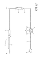
まず、本発明に係るコネクタの1つの実施形態について説明する。図1は、本実施形態としてのコネクタ1の断面図である。   First, one embodiment of a connector according to the present invention will be described. FIG. 1 is a cross-sectional view of a connector 1 according to this embodiment.

図1に示すように、コネクタ1は、ハウジング2と、このハウジング2に取り付けられる弾性弁体3と、を備える。   As shown in FIG. 1, the connector 1 includes a housing 2 and an elastic valve body 3 attached to the housing 2.

ハウジング2は、オスコネクタ100(図12参照)が外方から挿入される挿入口4を区画するキャップ5と、キャップ5を支持するホルダ6とを備える構成である。本実施形態では、キャップ5により区画された中空部70が挿入口4に該当する。   The housing 2 includes a cap 5 that defines an insertion port 4 into which the male connector 100 (see FIG. 12) is inserted from the outside, and a holder 6 that supports the cap 5. In the present embodiment, the hollow portion 70 partitioned by the cap 5 corresponds to the insertion port 4.

キャップ5は天面キャップ7と底面キャップ8を有しており、後述する弾性弁体3は、天面キャップ7及び底面キャップ8により圧縮、挟持されて中空部70内での位置が固定されている。なお、上述した挿入口4としての中空部70は、本実施形態では天面キャップ7と底面キャップ8とにより区画される。   The cap 5 has a top face cap 7 and a bottom face cap 8, and the elastic valve element 3 to be described later is compressed and sandwiched by the top face cap 7 and the bottom face cap 8 so that the position in the hollow portion 70 is fixed. Yes. In addition, the hollow part 70 as the insertion port 4 described above is partitioned by the top cap 7 and the bottom cap 8 in this embodiment.

ホルダ6は、天面キャップ7及び底面キャップ8を支持する部材である。なお、本実施形態では天面キャップ7及び底面キャップ8の両方がホルダ6に接触して支持される構成であるが、底面キャップ8を天面キャップ7に保持させて、天面キャップ7のみをホルダ6に接触させてホルダ6に支持させる構成を採用してもよい。また逆に天面キャップ7を底面キャップ8に保持させて、底面キャップ8のみをホルダ6に接触させてホルダ6に支持させる構成であってもよい。   The holder 6 is a member that supports the top cap 7 and the bottom cap 8. In the present embodiment, the top cap 7 and the bottom cap 8 are both supported by being in contact with the holder 6. However, the bottom cap 8 is held by the top cap 7 and only the top cap 7 is attached. A configuration in which the holder 6 is brought into contact with and supported by the holder 6 may be employed. Conversely, the top cap 7 may be held by the bottom cap 8, and only the bottom cap 8 may be brought into contact with the holder 6 and supported by the holder 6.

ハウジング2を構成するホルダ6、並びに、キャップ5としての天面キャップ7及び底面キャップ8の材料としては、例えば、ポリエチレン、ポリプロピレン、エチレン−プロピレン共重合体等のポリオレフィン;エチレン−酢酸ビニル共重合体(EVA);ポリ塩化ビニル;ポリ塩化ビニリデン;ポリスチレン;ポリアミド;ポリイミド;ポリアミドイミド;ポリカーボネート;ポリ−(4−メチルペンテン−1);アイオノマー;アクリル樹脂;ポリメチルメタクリレート;アクリロニトリル−ブタジエン−スチレン共重合体(ABS樹脂);アクリロニトリル−スチレン共重合体(AS樹脂);ブタジエン−スチレン共重合体;ポリエチレンテレフタレート(PET)、ポリブチレンテレフタレート(PBT)、ポリシクロヘキサンテレフタレート(PCT)等のポリエステル;ポリエーテル;ポリエーテルケトン(PEK);ポリエーテルエーテルケトン(PEEK);ポリエーテルイミド;ポリアセタール(POM);ポリフェニレンオキシド;変性ポリフェニレンオキシド;ポリサルフォン;ポリエーテルサルフォン;ポリフェニレンサルファイド;ポリアリレート;芳香族ポリエステル(液晶ポリマー);ポリテトラフルオロエチレン、ポリフッ化ビニリデン、その他フッ素系樹脂;などの各種樹脂材料が挙げられる。また、これらのうちの1種以上を含むブレンド体やポリマーアロイなどでもよい。その他に、各種ガラス材、セラミックス材料、金属材料であってもよい。   Examples of the material of the holder 6 constituting the housing 2 and the top cap 7 and the bottom cap 8 as the cap 5 include polyolefins such as polyethylene, polypropylene and ethylene-propylene copolymer; ethylene-vinyl acetate copolymer Polyvinyl chloride; Polyvinylidene chloride; Polystyrene; Polyamide; Polyimide; Polyamideimide; Polycarbonate; Poly- (4-methylpentene-1); Ionomer; Acrylic resin; Polymethyl methacrylate; Acrylonitrile-butadiene-styrene copolymer Polymer (ABS resin); Acrylonitrile-styrene copolymer (AS resin); Butadiene-styrene copolymer; Polyethylene terephthalate (PET), Polybutylene terephthalate (PBT), Polycyclohexane Polyesters such as phthalates (PCT); polyethers; polyether ketones (PEK); polyether ether ketones (PEEK); polyether imides; polyacetals (POM); polyphenylene oxides; modified polyphenylene oxides; Various resin materials such as sulfide; polyarylate; aromatic polyester (liquid crystal polymer); polytetrafluoroethylene, polyvinylidene fluoride, and other fluorine-based resins; Also, a blend or a polymer alloy containing one or more of these may be used. In addition, various glass materials, ceramic materials, and metal materials may be used.

弾性弁体3は、オスコネクタ100(図12参照)がコネクタ1に着脱される際に弾性変形して開閉することができるようにスリット9が設けられており、キャップ5としての天面キャップ7及び底面キャップ8により区画された挿入口4を閉塞するように配置されている。具体的に、弾性弁体3は、天面キャップ7と底面キャップ8とで構成される挟持部48(図6参照)により挟持されて、コネクタ1内での位置が固定される。   The elastic valve body 3 is provided with a slit 9 so that it can be elastically deformed and opened and closed when the male connector 100 (see FIG. 12) is attached to and detached from the connector 1. And the insertion port 4 defined by the bottom cap 8 is arranged to be closed. Specifically, the elastic valve body 3 is clamped by a clamping portion 48 (see FIG. 6) constituted by the top cap 7 and the bottom cap 8, and the position in the connector 1 is fixed.

弾性弁体3は、金型成形され、弾性変形可能に形成される。この弾性弁体3の材料としては、例えば、天然ゴム、イソプレンゴム、ブタジエンゴム、スチレン−ブタジエンゴム、ニトリルゴム、クロロプレンゴム、ブチルゴム、アクリルゴム、エチレン−プロピレンゴム、ヒドリンゴム、ウレタンゴム、シリコーンゴム、フッ素ゴムのような各種ゴム材料や、スチレン系、ポリオレフィン系、ポリ塩化ビニル系、ポリウレタン系、ポリエステル系、ポリアミド系、ポリブタジエン系、トランスポリイソプレン系、フッ素ゴム系、塩素化ポリエチレン系等の各種熱可塑性エラストマが挙げられ、これらのうちの1種または2種以上を混合したものであってもよい。   The elastic valve body 3 is molded and formed so as to be elastically deformable. Examples of the material of the elastic valve body 3 include natural rubber, isoprene rubber, butadiene rubber, styrene-butadiene rubber, nitrile rubber, chloroprene rubber, butyl rubber, acrylic rubber, ethylene-propylene rubber, hydrin rubber, urethane rubber, silicone rubber, Various rubber materials such as fluoro rubber, various heat such as styrene, polyolefin, polyvinyl chloride, polyurethane, polyester, polyamide, polybutadiene, trans polyisoprene, fluoro rubber, chlorinated polyethylene, etc. A plastic elastomer may be mentioned, and one or a mixture of two or more of these may be used.

また、弾性弁体3の硬度は、20〜60°(A硬度)であることが好ましい。これにより、弾性弁体3に適度な弾性力を確保することができるため、弾性弁体3に後述する弾性変形を生じさせることができる。   Moreover, it is preferable that the hardness of the elastic valve body 3 is 20-60 degrees (A hardness). Thereby, since an appropriate elastic force can be ensured in the elastic valve body 3, the elastic deformation described later can be caused in the elastic valve body 3.

以下に本実施形態における各部材及び各部材により構成される特徴部の詳細について説明する。   Details of each member and a characteristic part constituted by each member in the present embodiment will be described below.

[弾性弁体3]
図2は、弾性弁体3単体の斜視図である。図3A及び図3Bは、弾性弁体3単体の天面10及び底面11をそれぞれ示した図であり、図4A及び図4Bは、図3Bで示すI及びIIからそれぞれ見た弾性弁体3の側面図を示している。また、図5A及び図5Bは、図3Bにおける弾性弁体3のIII−III及びIV−IV断面図をそれぞれ示した図である。
[Elastic valve element 3]
FIG. 2 is a perspective view of the elastic valve body 3 alone. 3A and 3B are views showing the top surface 10 and the bottom surface 11 of the elastic valve body 3 alone, respectively. FIGS. 4A and 4B are views of the elastic valve body 3 viewed from I and II shown in FIG. 3B, respectively. A side view is shown. 5A and 5B are views respectively showing III-III and IV-IV sectional views of the elastic valve body 3 in FIG. 3B.

図2〜図5に示すように、弾性弁体3は、天面10側から見た場合に略円形の外形を有するディスク状のディスク状弁体であって、弾性弁体3は、図5に示すように、弾性弁体3の径方向Aにおいて、後述するハウジング2の挟持部48(図6参照)により挟持される括れ部12と、径方向Aにおいて挟持部48により挟持される位置よりも内側に位置する中央部13と、径方向Aにおいて挟持部48により挟持される位置よりも外側に位置する周縁部14と、を備えている。   As shown in FIGS. 2 to 5, the elastic valve body 3 is a disk-shaped disk-shaped valve body having a substantially circular outer shape when viewed from the top surface 10 side. As shown in FIG. 6, in the radial direction A of the elastic valve body 3, from the constricted portion 12 sandwiched by the sandwiching portion 48 (see FIG. 6) of the housing 2 described later, and the position sandwiched by the sandwiching portion 48 in the radial direction A. Also includes a central portion 13 positioned on the inner side and a peripheral edge portion 14 positioned on the outer side of the position clamped by the clamping portion 48 in the radial direction A.

弾性弁体3の外壁の一部である天面10は、中央部13の中央部天面領域15と、この中央部天面領域15よりも径方向Aにおいて外側に位置する括れ部12の括れ部天面領域16と、この括れ部天面領域15よりも径方向Aにおいて更に外側に位置する周縁部14の周縁部天面領域17と、で構成されている。   The top surface 10, which is a part of the outer wall of the elastic valve body 3, is constricted between a central top surface region 15 of the central portion 13 and a constricted portion 12 positioned outside in the radial direction A from the central top surface region 15. The top surface area 16 includes a top surface area 17 of the peripheral edge portion 14 located further outward in the radial direction A than the top surface area 15 of the constricted portion.

図2〜図5に示すように、中央部天面領域15は、括れ部天面領域16及び周縁部天面領域17よりも外方(図4、5において上方)において径方向Aに延在する平面状の中央平面部18と、この中央平面部18と直交する厚さ方向B(径方向Aに直交する方向)に延在する環状の側壁部19と、を有する。   As shown in FIGS. 2 to 5, the central top surface region 15 extends in the radial direction A outside (upward in FIGS. 4 and 5) outside the constricted portion top surface region 16 and the peripheral edge top surface region 17. A flat central plane portion 18 and an annular side wall portion 19 extending in a thickness direction B (a direction perpendicular to the radial direction A) orthogonal to the central plane portion 18.

中央平面部18の中央には一文字状のスリット9が形成されている。このスリット9は金型成形されるものであり、成形時には底面11まで貫通しておらず、金型成形後の例えば最初のオスコネクタ100の挿入時において、底面11まで貫通する構成としている。なお、スリット9を貫通させる工程を金型成形が完了した後に製造工程の一部として実行することも可能である。   A single-letter slit 9 is formed in the center of the central plane portion 18. The slit 9 is formed by molding, and does not penetrate to the bottom surface 11 at the time of molding, but penetrates to the bottom surface 11 when the first male connector 100 is inserted after molding, for example. In addition, it is also possible to perform the process of penetrating the slit 9 as a part of the manufacturing process after the mold forming is completed.

また、図3Aに示すように、中央部天面領域15の中央平面部18は、弾性弁体3が挿入口4(図1参照)に収容されていない状態で、スリット9の長手方向(図3Aにおいて上下方向)側に短軸を有し、スリット9の長手方向と直交する方向(図3Aにおいて左右方向)に長軸を有する楕円形状に形成されている。しかしながら、この中央部天面領域15の中央平面部18は、弾性弁体3が挿入口4に収容されると、楕円の長軸側で中央部天面領域15の側壁部19が天面キャップ7の内壁42(図1参照)に押されることにより円形を呈し、これに伴いスリット9の内面同士が密着して閉じられる。なお、図1、後に参照する図6〜図10、図14においては、スリット9を、構成の理解を容易にするため、密着して閉じられた状態として描いていないが、実際は内面同士が密着して閉じた状態となっている。   Further, as shown in FIG. 3A, the central flat surface portion 18 of the central top surface region 15 has a longitudinal direction of the slit 9 (see FIG. 3) in a state where the elastic valve element 3 is not accommodated in the insertion port 4 (see FIG. 1). 3A is formed in an elliptical shape having a minor axis on the side (up and down direction) and having a major axis in a direction orthogonal to the longitudinal direction of the slit 9 (left and right direction in FIG. 3A). However, when the elastic valve element 3 is accommodated in the insertion port 4, the central flat surface 18 of the central top surface region 15 has the side wall 19 of the central top surface region 15 on the long axis side of the ellipse. 7 is pushed into the inner wall 42 (see FIG. 1) to form a circular shape, and the inner surfaces of the slits 9 are in close contact with each other and closed. In FIG. 1 and FIGS. 6 to 10 and FIG. 14 to be referred to later, the slits 9 are not drawn in a close-closed state in order to facilitate understanding of the configuration. And is in a closed state.

ここで、図2〜図5に示すように、中央部天面領域15は、上述の中央平面部18及び側壁部19以外に、中央平面部18の外縁と側壁部19とを接続する曲面部20を有する。具体的に、曲面部20は、スリット9の長手方向と直交する断面(例えば図5Aに示す断面)の断面視で円弧形状を有しており、この曲面部20を介して中央平面部18と側壁部19とが接続されている。このように曲面部20を設けることにより、弾性弁体3がハウジング2に取り付けられた状態で、挿入されていたオスコネクタ100(図12参照)が抜去され、コネクタ1(図1参照)内に押し込まれていた弾性弁体3が復元力により所定の位置に戻る際に、弾性弁体3の天面10が、挿入口4の入口近傍に位置するハウジング2の内壁42(図1参照)に引っかかりにくくなる。更に、本実施形態では、図3Aに示すように、楕円形の中央平面部18の長軸方向(図3Aにおいてスリット9の長手方向と直交する方向)において、スリット9からの距離が遠い位置にある曲面部20ほど、同方向における曲面部20の長さLが長い構成となっている。これは、中央部天面領域15の中央平面部18の外縁のうち、楕円形の中央平面部18の長軸方向において、スリット9からの距離が遠い位置にある外縁ほど、弾性弁体3が復元力により所定の位置に戻る際に、ハウジング2の内壁42と引っかかりやすいためである。   Here, as shown in FIGS. 2 to 5, the central top surface region 15 is a curved surface portion that connects the outer edge of the central planar portion 18 and the sidewall portion 19 in addition to the central planar portion 18 and the sidewall portion 19 described above. 20 Specifically, the curved surface portion 20 has an arc shape in a cross-sectional view of a cross section orthogonal to the longitudinal direction of the slit 9 (for example, the cross section shown in FIG. 5A). The side wall 19 is connected. By providing the curved surface portion 20 in this manner, the inserted male connector 100 (see FIG. 12) is removed while the elastic valve body 3 is attached to the housing 2, and the connector 1 (see FIG. 1) is removed. When the pushed-in elastic valve body 3 returns to a predetermined position by a restoring force, the top surface 10 of the elastic valve body 3 is placed on the inner wall 42 (see FIG. 1) of the housing 2 located near the inlet of the insertion port 4. It becomes difficult to get caught. Further, in the present embodiment, as shown in FIG. 3A, in the major axis direction of the elliptical central plane portion 18 (the direction orthogonal to the longitudinal direction of the slit 9 in FIG. 3A), the distance from the slit 9 is far away. A certain curved surface portion 20 has a longer length L of the curved surface portion 20 in the same direction. This is because the elastic valve body 3 is located closer to the outer edge of the central plane portion 18 of the central top surface region 15 that is farther from the slit 9 in the major axis direction of the elliptical central plane portion 18. This is because the inner wall 42 of the housing 2 is easily caught when returning to a predetermined position by the restoring force.

なお、図5Bに示すように、本実施形態では、スリット9を含む、スリット9の長手方向に平行な断面で弾性弁体3を見た場合、中央平面部18の両端には円弧形状の曲面部20が設けられておらず、中央平面部18と側壁部19とが、略直角の角度で直接接続されているが、曲面部20を、中央平面部18の外縁全域に亘って設ける、すなわち弾性弁体3を天面10側から見た場合に中央平面部18の周囲を取り囲むように設けるようにしてもよい。   As shown in FIG. 5B, in the present embodiment, when the elastic valve body 3 is viewed in a cross section parallel to the longitudinal direction of the slit 9 including the slit 9, an arcuate curved surface is formed at both ends of the central plane portion 18. The portion 20 is not provided, and the central plane portion 18 and the side wall portion 19 are directly connected at a substantially right angle, but the curved surface portion 20 is provided over the entire outer edge of the central plane portion 18. When the elastic valve body 3 is viewed from the top surface 10 side, the elastic valve body 3 may be provided so as to surround the periphery of the central plane portion 18.

周縁部14の周縁部天面領域17は、図2及び図5に示すように、径方向Aに延在する平面状の周縁平面部21と、この周縁平面部21の内縁と連続し、周縁平面部21と直交する厚さ方向Bにおいて底面11側に進むにつれ、径方向Aにおける内径が漸減する環状の側壁部22と、を備える。なお、本実施形態の側壁部22は、図5A及び図5Bの断面視において、曲線状に延在しているが、同断面視において直線状に延在する構成としてもよい。また、本実施形態の側壁部22は、厚さ方向Bにおいて底面11側に進むにつれ、径方向Aにおける内径が漸減する構成であるが、厚さ方向Bに平行な円筒状としてもよい。但し、本実施形態のように、側壁部22を、周縁平面部21と直交する厚さ方向Bにおいて底面11側に進むにつれ、径方向Aにおける内径が漸減するテーパー形状とすれば、弾性弁体3を組み付ける際に、天面キャップ7の係止突起41(図6参照)が、周縁部天面領域17の側壁部22によって、中央部天面領域15の側壁部19に接触するように、更に、側壁部19を挿入口4(図6参照)側に押圧するようにガイドされるため、弾性弁体3のうち挟持部48(図6参照)によって挟持される径方向Aにおける位置がばらつくことが抑制される。更に、天面キャップ7の係止突起41は、側壁部22によって、側壁部19と接触するように、更には、側壁部19を径方向内側に押圧するようにガイドされるので、弾性弁体3を挟持部48により挟持する際に、挟持部48により圧縮された部分が挿入口4側に押し出されて弾性弁体3の中央部13の底面側で弛みが生じることを抑制することができる。この詳細は後述する(図11参照)。   As shown in FIGS. 2 and 5, the peripheral edge top surface region 17 of the peripheral edge portion 14 is continuous with the planar peripheral flat surface portion 21 extending in the radial direction A and the inner edge of the peripheral peripheral surface portion 21. And an annular side wall portion 22 in which the inner diameter in the radial direction A gradually decreases as it proceeds toward the bottom surface 11 in the thickness direction B orthogonal to the flat surface portion 21. In addition, although the side wall part 22 of this embodiment is extended in the curved line shape in sectional view of FIG. 5A and 5B, it is good also as a structure extended in linear form in the same sectional view. Moreover, although the side wall part 22 of this embodiment is the structure which the internal diameter in the radial direction A reduces gradually as it goes to the bottom face 11 side in the thickness direction B, it is good also as a cylindrical shape parallel to the thickness direction B. However, if the side wall portion 22 has a tapered shape in which the inner diameter in the radial direction A gradually decreases as the side wall portion 22 proceeds to the bottom surface 11 side in the thickness direction B orthogonal to the peripheral plane surface portion 21 as in this embodiment, the elastic valve body 3, the locking protrusion 41 (see FIG. 6) of the top cap 7 is in contact with the side wall 19 of the central top surface region 15 by the side wall 22 of the peripheral top surface region 17. Further, since the side wall portion 19 is guided so as to be pressed toward the insertion port 4 (see FIG. 6), the position in the radial direction A sandwiched by the sandwiching portion 48 (see FIG. 6) of the elastic valve body 3 varies. It is suppressed. Further, the locking projection 41 of the top cap 7 is guided by the side wall portion 22 so as to come into contact with the side wall portion 19 and further to press the side wall portion 19 radially inward. 3 is clamped by the clamping part 48, it can suppress that the part compressed by the clamping part 48 is pushed out to the insertion port 4 side, and slack arises in the bottom face side of the center part 13 of the elastic valve body 3. FIG. . Details of this will be described later (see FIG. 11).

括れ部12の括れ部天面領域16は、上述した中央部天面領域15の環状の側壁部19と、周縁部天面領域17の環状の側壁部22とを、対向する溝壁とする天面環状溝23の環状溝底24である。後述する天面キャップ7の係止突起41(図6参照)は、この天面環状溝23に入り込んで環状溝底24と接触し、弾性弁体3を圧縮して挟持部48を形成する。   The constricted portion top surface region 16 of the constricted portion 12 is a top surface in which the annular side wall portion 19 of the central top surface region 15 and the annular side wall portion 22 of the peripheral portion top surface region 17 are opposed groove walls. This is the annular groove bottom 24 of the surface annular groove 23. A locking protrusion 41 (see FIG. 6) of the top cap 7 described later enters the top surface annular groove 23 and contacts the annular groove bottom 24, and compresses the elastic valve body 3 to form a clamping portion 48.

弾性弁体3の天面10とは反対側の面であって、天面10と同様、弾性弁体の外壁の一部を構成する底面11は、中央部13の中央部底面領域25と、この中央部底面領域25よりも径方向Aにおいて外側に位置する括れ部12の括れ部底面領域26と、この括れ部底面領域26よりも径方向Aにおいて更に外側に位置する周縁部14の周縁部底面領域27と、で構成されている。   The bottom surface 11 which is the surface opposite to the top surface 10 of the elastic valve body 3 and constitutes a part of the outer wall of the elastic valve body, like the top surface 10, has a center bottom surface region 25 of the center portion 13, and The constricted portion bottom surface region 26 of the constricted portion 12 positioned outside in the radial direction A with respect to the central portion bottom surface region 25 and the peripheral portion of the peripheral portion 14 positioned further outward in the radial direction A with respect to the constricted portion bottom surface region 26. And a bottom area 27.

中央部底面領域25は、天面10側の中央平面部18と平行な面である底面11側の中央平面部28と、この中央平面部28よりも径方向Aの外側に位置すると共に、中央平面部28よりも外方(図4、5において下方)に突出する中央突出部29と、を備えている。   The center bottom surface region 25 is located on the outer side of the center plane portion 28 on the bottom surface 11 side, which is a surface parallel to the center plane portion 18 on the top surface 10 side, in the radial direction A from the center plane portion 28, and And a central projecting portion 29 projecting outward (downward in FIGS. 4 and 5) from the flat portion.

底面11側の中央平面部28には、スリット9は形成されていないが、上述したとおり、例えば最初のオスコネクタ100(図12参照)の挿入時において、弾性弁体3の天面10側の中央平面部18に形成されているスリット9の先端部と底面11側の中央平面部28との間の部分が裂けることによって、スリット9は天面10側の中央平面部18から底面11側の中央平面部28まで連通する。なお、図3Bには、説明の便宜上、天面10側にあるスリット9の位置を破線で示している。   Although the slit 9 is not formed in the central plane portion 28 on the bottom surface 11 side, as described above, for example, when the first male connector 100 (see FIG. 12) is inserted, the slit 10 is located on the top surface 10 side of the elastic valve body 3. When the portion between the front end portion of the slit 9 formed in the central plane portion 18 and the central plane portion 28 on the bottom surface 11 side is torn, the slit 9 is located on the bottom surface 11 side from the central plane portion 18 on the top surface 10 side. The center plane part 28 is communicated. In FIG. 3B, for convenience of explanation, the position of the slit 9 on the top surface 10 side is indicated by a broken line.

中央突出部29は、中央平面部28よりも外方に突出しているため、天面10側の中央平面部18と底面11側の中央平面部28との厚さ方向Bにおける肉厚よりも、天面10側の中央平面部18と中央突出部29との厚さ方向Bにおける肉厚の方が厚い。中央突出部29を設けない構成の場合には、オスコネクタ100の挿入時や抜去時などに弾性弁体3に過剰な負荷がかかってしまう時や、オスコネクタ100が繰り返し挿入及び抜去される場合に、連通したスリット9の底面11側の長手方向端部が裂けてしまうという問題があるが、中央突出部29を設けることによりスリット9の長手方向端部が補強されて上記問題の発生を抑制することが可能である。なお、本実施形態では、弾性弁体3を底面11側から見た場合に、中央平面部28を取り囲むように環状の中央突出部29が形成され、その中でも天面10に形成されたスリット9の長手方向の両側に対応する部分の肉厚が最も厚く形成されている。このような構成とすることにより、貫通したスリット9の長手方向における端部が裂けることを抑制すると共に、弾性弁体3のオスコネクタ挿入性の良さと弾性復元力の維持とを両立することが可能となる。   Since the central protruding portion 29 protrudes outward from the central flat portion 28, the thickness in the thickness direction B of the central flat portion 18 on the top surface 10 side and the central flat portion 28 on the bottom surface 11 side is greater than The thickness in the thickness direction B of the central flat portion 18 and the central protrusion 29 on the top surface 10 side is thicker. In the case where the central protrusion 29 is not provided, when the elastic valve body 3 is excessively loaded when the male connector 100 is inserted or removed, or when the male connector 100 is repeatedly inserted and removed. In addition, there is a problem in that the longitudinal end portion on the bottom surface 11 side of the slit 9 communicated with each other is torn, but the longitudinal end portion of the slit 9 is reinforced by providing the central protrusion 29 to suppress the occurrence of the above problem. Is possible. In the present embodiment, when the elastic valve body 3 is viewed from the bottom surface 11 side, an annular central protruding portion 29 is formed so as to surround the central flat portion 28, and among them, the slit 9 formed on the top surface 10. The thickness corresponding to both sides in the longitudinal direction is formed to be the thickest. By adopting such a configuration, it is possible to suppress tearing of the end portion in the longitudinal direction of the slit 9 that penetrates, and to achieve both good male connector insertability of the elastic valve body 3 and maintenance of elastic restoring force. It becomes possible.

また、中央突出部29の外縁には、厚さ方向Bに略平行な面と、厚さ方向Bに対して傾斜した面と、が周方向Eにおいて連続した環状の側壁部30が連続している。具体的には、図3B、図5A、及び図5Bに示すように、側壁部30のうちスリット9に対してスリット9の長手方向に直交する方向(図3Bにおいて短軸方向)に位置する部分は、厚さ方向Bに略平行な面で構成され、側壁部30のうちスリット9に対してスリット9の長手方向(図3Bにおいて長軸方向)に位置する部分は、厚さ方向Bで天面10側に向かうにつれて、径方向Aにおける外径が漸増する面で構成されている。   In addition, an annular side wall portion 30 in which a surface substantially parallel to the thickness direction B and a surface inclined with respect to the thickness direction B are continuous in the circumferential direction E is continuous with the outer edge of the central projecting portion 29. Yes. Specifically, as shown in FIGS. 3B, 5A, and 5B, a portion of the side wall portion 30 that is located in a direction perpendicular to the longitudinal direction of the slit 9 with respect to the slit 9 (short axis direction in FIG. 3B). Is configured by a plane substantially parallel to the thickness direction B, and a portion of the side wall portion 30 that is located in the longitudinal direction of the slit 9 with respect to the slit 9 (long axis direction in FIG. 3B) is the top in the thickness direction B. It is comprised by the surface where the outer diameter in radial direction A increases gradually as it goes to the surface 10 side.

周縁部底面領域27は、図5に示すように、径方向Aに延在する平面状の周縁平面部31と、この周縁平面部31の内縁と連続し、周縁平面部31と略直交する厚さ方向Bに延在する環状の側壁部32と、を備える。なお、本実施形態の側壁部32は、図5の断面視において厚さ方向Bに延在する構成であるが、厚さ方向Bにおいて天面10側に進むにつれ、径方向Aにおける内径が漸減する構成としてもよい。このような構成とすれば、後述するように、弾性弁体3を組み付ける際に、底面キャップ8の係止突起45(図6参照)が、周縁部底面領域27の側壁部32によって、中央部底面領域25の側壁部30に接触するように、更には、側壁部30を押圧するようにガイドされ、弾性弁体3のうち挟持部48(図6参照)によって挟持される径方向Aにおける位置がばらつくことが抑制される。更に、底面キャップ8の係止突起45は、周縁部底面領域27の側壁部32によって、中央部13の側壁部30と接触するように、更には側壁部30を径方向内側に押圧するようにガイドされるので、弾性弁体3を挟持部48(図6参照)により挟持する際に、挟持部48により圧縮された部分が挿入口4側に流れて、弾性弁体3の中央部13の底面11側で弛みが生じることを一層抑制することができる。詳細は後述する(図11参照)。   As shown in FIG. 5, the peripheral portion bottom surface region 27 is continuous with the planar peripheral flat portion 31 extending in the radial direction A and the inner edge of the peripheral flat portion 31, and has a thickness substantially orthogonal to the peripheral flat portion 31. An annular side wall portion 32 extending in the vertical direction B. The side wall portion 32 of the present embodiment is configured to extend in the thickness direction B in the cross-sectional view of FIG. 5, but the inner diameter in the radial direction A gradually decreases as it proceeds to the top surface 10 side in the thickness direction B. It is good also as composition to do. With such a configuration, as will be described later, when the elastic valve body 3 is assembled, the locking projection 45 (see FIG. 6) of the bottom cap 8 is moved by the side wall portion 32 of the peripheral bottom surface region 27 to the center portion. A position in the radial direction A that is guided so as to press the side wall portion 30 so as to contact the side wall portion 30 of the bottom region 25 and is clamped by the clamping portion 48 (see FIG. 6) of the elastic valve body 3. The variation is suppressed. Further, the locking protrusion 45 of the bottom cap 8 is brought into contact with the side wall portion 30 of the central portion 13 by the side wall portion 32 of the peripheral portion bottom surface region 27 and further presses the side wall portion 30 radially inward. Since it is guided, when the elastic valve body 3 is clamped by the clamping portion 48 (see FIG. 6), the portion compressed by the clamping portion 48 flows to the insertion port 4 side, and the central portion 13 of the elastic valve body 3 It is possible to further suppress the occurrence of slack on the bottom surface 11 side. Details will be described later (see FIG. 11).

括れ部12の括れ部底面領域26は、上述した中央部底面領域25の環状の側壁部30と、周縁部底面領域27の環状の側壁部32と、を溝壁とする底面環状溝33の環状溝底34である。後述する底面キャップ8の係止突起45は、この底面環状溝33に入り込んで環状溝底34と接触し、底面キャップ7の係止突起41と共に弾性弁体3を圧縮、挟持して挟持部48を形成する(図6参照)。   The constricted portion bottom surface region 26 of the constricted portion 12 is an annular shape of a bottom annular groove 33 having the annular side wall portion 30 of the central bottom surface region 25 and the annular side wall portion 32 of the peripheral portion bottom surface region 27 described above as groove walls. This is the groove bottom 34. A locking projection 45 of the bottom cap 8 to be described later enters the bottom annular groove 33 and comes into contact with the annular groove bottom 34, and compresses and clamps the elastic valve body 3 together with the locking projection 41 of the bottom cap 7 to sandwich the clamping portion 48. (See FIG. 6).

なお、図2〜図5に示すように、弾性弁体3の天面10における周縁部天面領域17の径方向Aにおける外縁と、底面11における周縁部底面領域27の径方向Aにおける外縁とは、天面10及び底面11と共に弾性弁体3の外壁を構成する環状の側壁部35により接続されている。なお、本実施形態の側壁部35は、図4、図5に示すように、厚さ方向Bに平行する外周面である。   2 to 5, the outer edge in the radial direction A of the peripheral edge top surface region 17 on the top surface 10 of the elastic valve element 3, and the outer edge in the radial direction A of the peripheral edge bottom surface region 27 on the bottom surface 11. Are connected together with the top surface 10 and the bottom surface 11 by an annular side wall 35 constituting the outer wall of the elastic valve body 3. In addition, the side wall part 35 of this embodiment is an outer peripheral surface parallel to the thickness direction B, as shown in FIG. 4, FIG.

[天面キャップ7]
図6は、上述した弾性弁体3が、天面キャップ7と底面キャップ8とに挟持されている状態を示す拡大断面図である。図1及び図6を参照しながら天面キャップ7、底面キャップ8、及びホルダ6の構成を以下に説明する。
[Top cap 7]
FIG. 6 is an enlarged cross-sectional view showing a state where the elastic valve body 3 described above is sandwiched between the top cap 7 and the bottom cap 8. The configurations of the top cap 7, the bottom cap 8, and the holder 6 will be described below with reference to FIGS.

図1に示すように、天面キャップ7は、略円筒状の中空筒部36と、この中空筒部36の一端側に設けられたフランジ部37により構成されている。図6に示すように中空筒部36の他端側である上面(図6における上面)は、弾性弁体3の径方向A(図1、図6では、オスコネクタ100の挿入方向Cに直交する方向と同じ方向)に延在する平面状の延在部38である。この延在部38には、オスコネクタ100が外方より挿入される挿入口4の一端を区画する略円形の縁39が含まれる。中空筒部36の外周面にはISO594で規定されたロックコネクタと螺合することができるようにねじ山40が形成されている。フランジ部37は、中空筒部36と一体で型成形された部位であり、フランジ部37が後述するホルダ6と係合することにより天面キャップ7がホルダ6に保持される構成である。   As shown in FIG. 1, the top cap 7 includes a substantially cylindrical hollow cylinder portion 36 and a flange portion 37 provided on one end side of the hollow cylinder portion 36. As shown in FIG. 6, the upper surface (the upper surface in FIG. 6) that is the other end side of the hollow cylindrical portion 36 is perpendicular to the radial direction A of the elastic valve element 3 (in FIGS. 1 and 6, the insertion direction C of the male connector 100 is orthogonal). It is the planar extension part 38 extended in the same direction as the direction to do. The extending portion 38 includes a substantially circular edge 39 that defines one end of the insertion port 4 into which the male connector 100 is inserted from the outside. A thread 40 is formed on the outer peripheral surface of the hollow cylindrical portion 36 so as to be able to be screwed into a lock connector defined by ISO594. The flange portion 37 is a part molded integrally with the hollow cylindrical portion 36, and has a configuration in which the top cap 7 is held by the holder 6 when the flange portion 37 engages with the holder 6 described later.

図6に示すように、中空筒部36の内壁のうち縁39の近傍には、オスコネクタ100の挿入方向Cに向かって突出し、上述した弾性弁体3の天面環状溝23(図2、図3、及び図5参照)に入り込んで、底面キャップ8の係止突起45と共に弾性弁体3を圧縮する係止突起41が設けられている。縁39と係止突起41の間に形成される、天面キャップ7の環状の内壁42は、オスコネクタ100が挿入されていない状態では上述した弾性弁体3の中央部天面領域15の側壁部19(図2〜図5参照)と接触し、オスコネクタ100が挿入されている状態(図12参照)ではオスコネクタ100と接触するように構成されている。つまり、オスコネクタ100が挿入されていない状態では、弾性弁体3の中央部天面領域15(図2〜図5参照)が内壁42により囲まれる略円柱状の空間に嵌り込み、オスコネクタ100が挿入されている状態ではオスコネクタ100が円筒状の内壁42により天面キャップ7と嵌合する。なお、本実施形態における内壁42は、挿入方向Cに対して平行な円筒状であるが、オスコネクタ100の外形に応じて、挿入方向Cに向かって漸減的に内径が小さくなるテーパー状としてもよい。   As shown in FIG. 6, in the vicinity of the edge 39 on the inner wall of the hollow cylindrical portion 36, the projection protrudes in the insertion direction C of the male connector 100, and the top annular groove 23 (FIG. 2, FIG. 2) of the elastic valve body 3 described above. 3 and FIG. 5), a locking projection 41 that compresses the elastic valve body 3 is provided together with the locking projection 45 of the bottom cap 8. An annular inner wall 42 of the top cap 7 formed between the edge 39 and the locking projection 41 is a side wall of the above-described central top surface region 15 of the elastic valve body 3 when the male connector 100 is not inserted. It contacts with the part 19 (refer FIGS. 2-5), and is comprised so that the male connector 100 may be contacted in the state (refer FIG. 12) in which the male connector 100 is inserted. That is, in a state where the male connector 100 is not inserted, the central top surface region 15 (see FIGS. 2 to 5) of the elastic valve body 3 is fitted into a substantially cylindrical space surrounded by the inner wall 42, and the male connector 100. In the state in which is inserted, the male connector 100 is fitted to the top cap 7 by the cylindrical inner wall 42. The inner wall 42 in the present embodiment has a cylindrical shape parallel to the insertion direction C. However, the inner wall 42 may have a tapered shape whose inner diameter gradually decreases in the insertion direction C according to the outer shape of the male connector 100. Good.

また、図6に示すように、オスコネクタ100が挿入されていない状態では、弾性弁体3の中央部天面領域15のうち、弾性弁体3の径方向Aに延在する中央平面部18は、縁39よりも、オスコネクタ挿入方向Cの逆方向D側に位置している。すなわち、中央部天面領域15の一部が、縁39よりも逆方向D側に突出している。   Further, as shown in FIG. 6, in the state where the male connector 100 is not inserted, the central flat surface portion 18 extending in the radial direction A of the elastic valve body 3 in the central top surface region 15 of the elastic valve body 3. Is positioned on the opposite direction D side of the male connector insertion direction C from the edge 39. That is, a part of the central top surface region 15 protrudes in the reverse direction D side from the edge 39.

このような構成とすることにより、医療従事者などの使用者が弾性弁体3の外壁である天面10付近に付着した薬液等をふき取る際に、弾性弁体3がコネクタ1の内方(オスコネクタ100の挿入方向C)に多少押し込まれたとしても、この押し込みによって弾性弁体3の中央部天面領域15と、天面キャップ7における縁39と、の間に段差(内壁42が外部に露出するような段差)が形成されにくくなるため、薬液等をふき取り易い。   With such a configuration, when a user such as a medical worker wipes off a chemical solution or the like adhering to the vicinity of the top surface 10 which is the outer wall of the elastic valve body 3, the elastic valve body 3 is connected to the inside of the connector 1 ( Even if the male connector 100 is slightly pushed in the insertion direction C), a step (inner wall 42 is externally connected) between the central top surface region 15 of the elastic valve body 3 and the edge 39 of the top cap 7 by this pushing. It is easy to wipe off the chemical solution and the like.

[底面キャップ8]
図1に示すように、底面キャップ8は、天面キャップ7と同様、略円筒状の中空筒部43と、中空筒部43の一端側に設けられたフランジ部44とを備える構成である。中空筒部43の他端側には、オスコネクタ100の挿入方向Cとは逆方向Dに向かって突出し、上述した弾性弁体3の底面環状溝33(図3B、図5参照)に入り込んで、天面キャップ7の係止突起41と共に弾性弁体3を圧縮し、挟持する係止突起45が設けられている(図6参照)。
[Bottom cap 8]
As shown in FIG. 1, the bottom cap 8 is configured to include a substantially cylindrical hollow cylinder portion 43 and a flange portion 44 provided on one end side of the hollow cylinder portion 43, as with the top cap 7. The other end side of the hollow cylindrical portion 43 protrudes in the direction D opposite to the insertion direction C of the male connector 100 and enters the bottom annular groove 33 (see FIGS. 3B and 5) of the elastic valve body 3 described above. A locking projection 45 is provided to compress and clamp the elastic valve body 3 together with the locking projection 41 of the top cap 7 (see FIG. 6).

底面キャップ8は、天面キャップ7の中空筒部36の内面及び/又はフランジ部37の下面(図1における下面)に超音波接着されることにより天面キャップ7により保持され、更に底面キャップ8のフランジ部44を後述するホルダ6により支持することにより位置が固定されている。   The bottom cap 8 is held by the top cap 7 by ultrasonic bonding to the inner surface of the hollow cylindrical portion 36 of the top cap 7 and / or the lower surface of the flange portion 37 (the lower surface in FIG. 1). The position is fixed by supporting the flange portion 44 by a holder 6 described later.

[ホルダ6]
図1に示すように、ホルダ6は、天面キャップ7及び底面キャップ8を支持し、その内部に中空部71を区画している。本実施形態のホルダ6は、天面キャップ7及び底面キャップ8と直接接触することにより両者を支持しているが、例えばホルダ6が天面キャップ7とは接触せずに底面キャップ8のみと直接接触し、天面キャップ7は底面キャップ8に接触、支持させる構成としてもよい。すなわちホルダ6が天面キャップ7と底面キャップ8とのいずれか一方と直接接触して支持し、他方とは直接接触しない構成としてもよい。なお、直接接触する部材同士は、例えば超音波接着などにより接着するようにすることが好ましい。
[Holder 6]
As shown in FIG. 1, the holder 6 supports the top cap 7 and the bottom cap 8, and defines a hollow portion 71 therein. The holder 6 according to the present embodiment supports both the top surface cap 7 and the bottom surface cap 8 by directly contacting them. For example, the holder 6 does not contact the top surface cap 7 and directly contacts only the bottom surface cap 8. The top cap 7 may be in contact with and supported by the bottom cap 8. That is, the holder 6 may be configured to directly contact and support one of the top cap 7 and the bottom cap 8 and not directly contact the other. In addition, it is preferable to adhere | attach the members which contact directly, for example by ultrasonic bonding.

また、オスコネクタ100が挿入されていない状態では、天面キャップ7の内壁と底面キャップ8の内壁とで区画される挿入口4(中空部70)と、中空部71とが連通している。ここで、挿入口4と中空部71とが「連通する」とは、両空間が繋がっていることを意味しており、両空間が直接繋がっていることのみならず、別の空間を介して繋がっていることも含む意味である。なお、図1に示す本実施形態における挿入口4と中空部71とは、直接繋がっている構成である。   When the male connector 100 is not inserted, the insertion port 4 (hollow part 70) defined by the inner wall of the top cap 7 and the inner wall of the bottom cap 8 and the hollow part 71 communicate with each other. Here, that the insertion port 4 and the hollow portion 71 “communicate” means that both spaces are connected, and not only that both spaces are directly connected but also through another space. It also means that they are connected. In addition, the insertion port 4 and the hollow part 71 in this embodiment shown in FIG. 1 are the structures connected directly.

また、詳細は後述するが、コネクタ1にオスコネクタ100が挿入されるときは、オスコネクタ100の先端部101が挿入口4を通って中空部71内或いはその近傍まで入り込み、オスコネクタ100内の液体流路とホルダ6の中空部71とが連通する。   Although details will be described later, when the male connector 100 is inserted into the connector 1, the distal end portion 101 of the male connector 100 enters the hollow portion 71 or the vicinity thereof through the insertion port 4, The liquid flow path and the hollow portion 71 of the holder 6 communicate with each other.

更に図1に示すように、本実施形態におけるホルダ6は、内周面にロックコネクタ用のねじ山が設けられた略円筒状の外筒部46と、この外筒部46が区画する中空部に設けられたオスルアー部47と、を備えるものであるが、このホルダ6の形状に限定されるものではなく各種ホルダが使用可能であり、ユーザーの使用用途等に応じて適宜変更可能である。例えば、図7Aに示すようなホルダ60を備えるコネクタ110が挙げられる。ホルダ60は、中空部を内部に有する略円筒状の筐体からなるホルダ本体61と、ホルダ本体61の外周面から突出した円筒状の上流ポート部62及び下流ポート部63とを備える。ホルダ本体61内部の中空は、上流ポート部62から下流ポート部63に達する液体流路64の一部を担っている。またホルダ60の外壁上に天面キャップ7及び底面キャップ8が支持されている。図7Aに示すホルダ60は、内部の液体流路の形状や、液体流路の形状に伴う外形が、ホルダ6とは異なるが、弾性弁体3、天面キャップ7、底面キャップ8は上述したものと同一のものが使用可能である。   Further, as shown in FIG. 1, the holder 6 in this embodiment includes a substantially cylindrical outer cylinder portion 46 having a lock connector thread on the inner peripheral surface, and a hollow portion defined by the outer cylinder portion 46. However, the holder 6 is not limited to the shape of the holder 6, and various holders can be used, and can be appropriately changed according to the user's usage. For example, the connector 110 provided with the holder 60 as shown to FIG. 7A is mentioned. The holder 60 includes a holder main body 61 formed of a substantially cylindrical casing having a hollow portion therein, and a cylindrical upstream port portion 62 and a downstream port portion 63 protruding from the outer peripheral surface of the holder main body 61. The hollow inside the holder body 61 serves as a part of the liquid flow path 64 that reaches the downstream port part 63 from the upstream port part 62. A top cap 7 and a bottom cap 8 are supported on the outer wall of the holder 60. The holder 60 shown in FIG. 7A is different from the holder 6 in the shape of the internal liquid flow path and the shape of the liquid flow path, but the elastic valve body 3, the top cap 7 and the bottom cap 8 have been described above. The same can be used.

また更に、上述のホルダ60の他に、図7Bに示すような、ホルダ600を、ホルダ6に代えて用いることも可能である。図7Bは、コネクタ120としての三方活栓を示す。この三方活栓におけるホルダ600は、コック601を内部に収容する略円筒状のホルダ本体602と、ホルダ本体602の外壁に設けられた、略円筒状の上流ポート部603と、ホルダ本体602を挟み、上流ポート部603とは反対側の位置でホルダ本体602の外壁に設けられた、略円筒状の下流ポート部604と、上流ポート部603及び下流ポート部604の位置とは異なる位置で、ホルダ本体602の外壁に設けられた分岐ポート部605と、を備える。ホルダ600の内部には、図7Bにおいて矢印で示すような液体流路606を形成することができる。弾性弁体3、天面キャップ7、及び底面キャップ8は、図7Bに示すホルダ600の分岐ポート部605の端部に設けられ、ホルダ600により支持される。   Furthermore, in addition to the holder 60 described above, a holder 600 as shown in FIG. 7B can be used instead of the holder 6. FIG. 7B shows a three-way cock as the connector 120. The holder 600 in this three-way stopcock sandwiches the substantially cylindrical holder main body 602 that houses the cock 601 inside, the substantially cylindrical upstream port portion 603 provided on the outer wall of the holder main body 602, and the holder main body 602. The holder main body at a position different from the positions of the substantially cylindrical downstream port section 604 and the upstream port section 603 and the downstream port section 604 provided on the outer wall of the holder main body 602 at a position opposite to the upstream port section 603. And a branch port portion 605 provided on the outer wall of 602. A liquid channel 606 as shown by an arrow in FIG. 7B can be formed inside the holder 600. The elastic valve body 3, the top cap 7, and the bottom cap 8 are provided at the end of the branch port portion 605 of the holder 600 shown in FIG. 7B and supported by the holder 600.

ここで、本実施形態では、弾性弁体3を、キャップ5を構成する天面キャップ7と底面キャップ8とにより挟持する構成としているが、このような構成に限られるものではない。例えば、底面キャップ8とホルダ6とを単一の部材で構成し、ホルダ6自体に底面キャップ8の機能を持たせ、キャップ5を構成する天面キャップ7と、ホルダ6と、で弾性弁体3を挟持するようにしてもよい。また、ホルダ6の形状の代わりにホルダ60の形状を用いて、底面キャップ8とホルダ60とを単一の部材で構成するようにしてもよいし、ホルダ6の形状の代わりにホルダ600の形状を用いて、底面キャップ8とホルダ600とを単一の部材で構成するようにしてもよい。   Here, in the present embodiment, the elastic valve body 3 is configured to be sandwiched between the top cap 7 and the bottom cap 8 constituting the cap 5, but is not limited to such a configuration. For example, the bottom cap 8 and the holder 6 are formed of a single member, the holder 6 itself has the function of the bottom cap 8, and the top face cap 7 constituting the cap 5 and the holder 6 are elastic valve bodies. 3 may be clamped. Further, the shape of the holder 60 may be used instead of the shape of the holder 6, and the bottom cap 8 and the holder 60 may be configured by a single member, or the shape of the holder 600 may be used instead of the shape of the holder 6. The bottom cap 8 and the holder 600 may be configured with a single member.

[弾性弁体3を挟持する挟持部48]
次に、弾性弁体3を天面キャップ7と底面キャップ8とで圧縮し、挟持する構成について詳しく説明する。
[Clamping portion 48 for clamping the elastic valve body 3]
Next, the structure in which the elastic valve body 3 is compressed and clamped by the top cap 7 and the bottom cap 8 will be described in detail.

図6に示すように、弾性弁体3は、天面キャップ7の中空筒部36及び底面キャップ8の中空筒部43により区画される中空部70(挿入口4)を閉塞するように取り付けられている。具体的に、挟持部48が弾性弁体3のスリット9が形成された天面10、及びこの天面10の反対側の底面11に接触して、弾性弁体3を挟持することにより、弾性弁体3の中空部70内での位置が固定される。より具体的には、天面キャップ7の係止突起41が弾性弁体3の天面環状溝23(図5等参照)に入り込み、そして底面キャップ8の係止突起45が弾性弁体3の底面環状溝33に入り込み、弾性弁体3を天面10の溝底24(図5等参照)及び底面11の溝底34から圧縮することにより挟持部48を形成し、弾性弁体3の中空部70における位置を固定する。なお、本実施形態における弾性弁体3の括れ部12は、挟持部48により挟持される前の状態で厚さ方向Bにおいて1.0mm程度の厚みを有するものであるが、挟持部48の圧縮によって、厚さ方向Bにおいて弾性変形できなくなる薄さ(例えば0.2〜0.3mm)になるまで圧縮されが、この圧縮量は一例であって、弾性弁体の形状や大きさ等に応じて適宜変更することが可能である。   As shown in FIG. 6, the elastic valve body 3 is attached so as to close the hollow portion 70 (insertion port 4) defined by the hollow cylindrical portion 36 of the top cap 7 and the hollow cylindrical portion 43 of the bottom cap 8. ing. Specifically, the clamping portion 48 comes into contact with the top surface 10 where the slit 9 of the elastic valve body 3 is formed and the bottom surface 11 opposite to the top surface 10 to sandwich the elastic valve body 3. The position in the hollow part 70 of the valve body 3 is fixed. More specifically, the locking projection 41 of the top cap 7 enters the top surface annular groove 23 (see FIG. 5 and the like) of the elastic valve body 3, and the locking projection 45 of the bottom cap 8 forms the elastic valve body 3. The elastic valve body 3 enters the bottom annular groove 33 and compresses the elastic valve body 3 from the groove bottom 24 (see FIG. 5 and the like) of the top surface 10 and the groove bottom 34 of the bottom surface 11 to form a clamping portion 48. The position in the part 70 is fixed. The constricted portion 12 of the elastic valve body 3 in this embodiment has a thickness of about 1.0 mm in the thickness direction B before being sandwiched by the sandwiching portion 48. Is compressed until it becomes thin (for example, 0.2 to 0.3 mm) that cannot be elastically deformed in the thickness direction B. This amount of compression is an example, and depends on the shape and size of the elastic valve body. Can be changed as appropriate.

ここで挟持部48は、弾性弁体3の天面10に接触する天面側挟持部49と、弾性弁体3の底面11に接触して、天面側挟持部49と共に弾性弁体3を挟持する底面側挟持部50とで構成され、弾性弁体3を天面10側から見た場合に、挟持部48はスリット9を取り囲むように略円形に設けられている。なお、本実施形態における天面側挟持部49は、天面キャップ7の係止突起41の先端部であり、底面側挟持部50は、底面キャップ8の係止突起45の先端部である。また、弾性弁体3を「天面10側から見た場合」とは、弾性弁体3を天面10側から見た仮想平面上に天面側挟持部49と底面側挟持部50とを投影した場合を意味しており、実際に目視できるか否かを意味するものではない。   Here, the clamping part 48 contacts the top surface side clamping part 49 that contacts the top surface 10 of the elastic valve element 3 and the bottom surface 11 of the elastic valve element 3, and the elastic valve element 3 together with the top surface side clamping part 49. It is comprised by the bottom face side clamping part 50 to clamp, and when the elastic valve body 3 is seen from the top | upper surface 10 side, the clamping part 48 is provided in the substantially circular shape so that the slit 9 may be surrounded. In addition, the top surface side clamping part 49 in this embodiment is a front-end | tip part of the latching protrusion 41 of the top-surface cap 7, and the bottom face side clamping part 50 is a front-end | tip part of the latching protrusion 45 of the bottom surface cap 8. FIG. In addition, when the elastic valve body 3 is viewed from the top surface 10 side, the top surface side clamping portion 49 and the bottom surface side clamping portion 50 are arranged on a virtual plane when the elastic valve body 3 is viewed from the top surface 10 side. It means the case where it is projected, and does not mean whether or not it can actually be seen.

弾性弁体3は、挟持部48により挟持されている状態において、天面10側から見た場合に、挟持部48により挟持される括れ部12と、括れ部12よりも径方向Aにおいて内側に位置する中央部13と、括れ部12よりも径方向Aにおいて外側に位置する周縁部14と、を備える。   When viewed from the top surface 10 side, the elastic valve body 3 is sandwiched by the sandwiching portion 48 and the constricted portion 12 sandwiched by the sandwiching portion 48 and the inner side in the radial direction A from the constricted portion 12. The center part 13 located and the peripheral part 14 located in the outer side in radial direction A rather than the narrow part 12 are provided.

なお、同状態において、弾性弁体3の周縁部14は、天面キャップ7の内壁の一部及び底面キャップ8の外壁の一部により周囲を囲まれている。この詳細については後述する(図8等参照)。   In this state, the peripheral edge 14 of the elastic valve body 3 is surrounded by a part of the inner wall of the top cap 7 and a part of the outer wall of the bottom cap 8. Details of this will be described later (see FIG. 8 and the like).

また、本実施形態における挟持部48は、弾性弁体3を天面10側から見た場合に、弾性弁体3の周方向E(図3参照)全域に亘って設けられているが、例えば、櫛歯状の突起により周方向Eにおいて所定間隔ごと離して配置するなど、周方向Eの一部のみに設けられている構成とすることも可能である。但し、挟持部48を、本実施形態のように周方向E全域に設け、周方向E全域において弾性弁体3の天面10及び底面11と接触するよう構成すれば、オスコネクタの挿入及び抜去の繰り返しに対して弾性弁体3の括れ部12及び周縁部14が、挿入口4側へと移動することを一層抑制することができる。   Moreover, when the elastic valve body 3 is seen from the top surface 10 side, the clamping part 48 in this embodiment is provided over the circumferential direction E (refer FIG. 3) of the elastic valve body 3, for example, It is also possible to adopt a configuration in which only a part of the circumferential direction E is provided, such as being arranged at predetermined intervals in the circumferential direction E by comb-like protrusions. However, if the clamping portion 48 is provided in the entire circumferential direction E as in the present embodiment and is configured to contact the top surface 10 and the bottom surface 11 of the elastic valve body 3 in the entire circumferential direction E, the male connector is inserted and removed. It can further suppress that the narrow part 12 and the peripheral part 14 of the elastic valve body 3 move to the insertion port 4 side with respect to repetition of these.

更に、本実施形態の挟持部48は、ハウジング2により構成されている。具体的に、本実施形態の挟持部48は、天面キャップ7の係止突起41の先端部と、底面キャップ8の係止突起45の先端部と、で構成されているが、挟持部48の形態はこれに限られるものではない。例えば、ハウジングを構成する部材以外の部材により挟持部を構成するようにしてもよい。また、ハウジングが挟持部を構成する場合であっても、本実施形態における挟持部48の形態に限られるものではなく、例えば、ハウジングが、弾性弁体の天面側に位置する天面側部材と、弾性弁体の底面側に位置する底面側部材と、天面側部材と底面側部材との間に位置し、これらに挟持されることにより弾性弁体の天面及び底面に直接接触して弾性弁体を挟持する接触部材と、を備え、この接触部材により挟持部を構成するようにしてもよい。かかる場合には、天面側部材と底面側部材とで接触部材を挟み込むことにより挟持部を形成するため、天面側部材及び底面側部材が、弾性弁体の天面及び底面には直接接触しない構成となる。   Furthermore, the clamping portion 48 of the present embodiment is configured by the housing 2. Specifically, the sandwiching portion 48 of the present embodiment is configured by the distal end portion of the locking projection 41 of the top cap 7 and the distal end portion of the locking projection 45 of the bottom cap 8. The form of is not limited to this. For example, the clamping unit may be configured by a member other than the members configuring the housing. Further, even when the housing constitutes the clamping portion, the configuration is not limited to the configuration of the clamping portion 48 in the present embodiment. For example, the top surface side member in which the housing is located on the top surface side of the elastic valve body And the bottom surface side member positioned on the bottom surface side of the elastic valve body, and the top surface side member and the bottom surface side member are positioned between and directly contact the top surface and the bottom surface of the elastic valve body. And a contact member that sandwiches the elastic valve body, and the contact member may constitute the sandwiching portion. In such a case, the top surface side member and the bottom surface side member are in direct contact with the top surface and bottom surface of the elastic valve body because the sandwiching portion is formed by sandwiching the contact member between the top surface side member and the bottom surface side member. It becomes the composition which does not.

[弾性弁体3の周縁部14の体積について]
次に、弾性弁体3が、ハウジング2における挟持部48により、換言すれば天面キャップ7及び底面キャップ8の係止突起41及び45により構成される天面側挟持部49及び底面側挟持部50により、挟持されている状態での周縁部14の体積と、弾性弁体3が挟持部48により挟持されていない状態での周縁部14の体積と、の関係について説明する。
[Volume of peripheral edge 14 of elastic valve element 3]
Next, the elastic valve body 3 is held by the holding portion 48 in the housing 2, in other words, the top surface side holding portion 49 and the bottom surface side holding portion constituted by the locking projections 41 and 45 of the top cap 7 and the bottom cap 8. 50, the relationship between the volume of the peripheral edge portion 14 in the state of being sandwiched and the volume of the peripheral edge portion 14 in a state in which the elastic valve body 3 is not sandwiched by the sandwiching portion 48 will be described.

なお、「弾性弁体が挟持部により挟持されている状態」とは、図1等で示すような、弾性弁体がコネクタ内に組み付けられ、医療従事者等のユーザーがコネクタとして使用可能な状態を意味する。また、「弾性弁体が挟持部により挟持されていない状態」とは、弾性弁体がコネクタ内に組み付けられていない状態、すなわち、例えば図2〜図5に示すような弾性弁体単体での状態を意味する。   The “state in which the elastic valve body is clamped by the clamping portion” means a state in which the elastic valve body is assembled in the connector and can be used as a connector by a user such as a medical worker as shown in FIG. Means. Further, “the state in which the elastic valve body is not clamped by the clamping portion” means a state in which the elastic valve body is not assembled in the connector, that is, for example, a single elastic valve body as shown in FIGS. Means state.

本実施形態では、弾性弁体3が挟持部48により挟持されている状態での周縁部14の体積V1は、弾性弁体3が挟持部48により挟持されていない状態での周縁部14の体積V2よりも大きい。   In the present embodiment, the volume V1 of the peripheral edge 14 when the elastic valve body 3 is clamped by the clamping section 48 is the volume of the peripheral edge 14 when the elastic valve body 3 is not clamped by the clamping section 48. Greater than V2.

まず、本実施形態としてのコネクタ1の比較例としてのコネクタ200について説明する。図14は、比較例としてのコネクタ200を示す。このコネクタ200は、本実施形態としてのコネクタ1と、弾性弁体が挟持部により挟持される前後で周縁部の体積を変化させない点で異なる。図14Aは、コネクタ200の弾性弁体203が挟持部248により挟持されていない状態を示し、図14Bは、弾性弁体203が挟持部248により挟持されている状態を示す。なお、図14Aの破線は、弾性弁体203が挟持部248により挟持されている状態での底面キャップ208の位置を示している。   First, a connector 200 as a comparative example of the connector 1 according to the present embodiment will be described. FIG. 14 shows a connector 200 as a comparative example. The connector 200 is different from the connector 1 according to the present embodiment in that the volume of the peripheral portion is not changed before and after the elastic valve body is sandwiched by the sandwiching portion. 14A shows a state where the elastic valve body 203 of the connector 200 is not clamped by the clamping part 248, and FIG. 14B shows a state where the elastic valve body 203 is clamped by the clamping part 248. 14A indicates the position of the bottom cap 208 in a state where the elastic valve body 203 is sandwiched by the sandwiching portion 248.

図14で示すように、弾性弁体203が挟持部248により挟持されていない状態での弾性弁体203の周縁部214は、弾性弁体203が挟持部248により挟持されている状態での収容空間251(図14Aでは、実線の天面キャップ207と破線の底面キャップ208とで区画される空間であり、図14Bでは、実線の天面キャップ207と破線の底面キャップ208とで区画される空間)よりも既に大きい。つまり、弾性弁体203が挟持部248により挟持されていない図14Aに示す状態から、挟持部248により挟持されている図14Bに示す状態へと変化させる際に、弾性弁体203の周縁部214は、収容空間251を区画する壁面により圧縮されて体積が減少することになる。   As shown in FIG. 14, the peripheral edge 214 of the elastic valve body 203 in a state where the elastic valve body 203 is not clamped by the clamping portion 248 is accommodated in a state where the elastic valve body 203 is clamped by the clamping portion 248. Space 251 (in FIG. 14A, a space defined by a solid top cap 207 and a broken bottom cap 208, and in FIG. 14B, a space defined by a solid top cap 207 and a broken bottom cap 208. Already larger than). That is, when changing from the state shown in FIG. 14A in which the elastic valve body 203 is not held by the holding portion 248 to the state shown in FIG. 14B held in the holding portion 248, the peripheral portion 214 of the elastic valve body 203 Will be compressed by the wall surface which divides the accommodation space 251, and a volume will reduce.

そのため、挟持部248の圧縮によって、括れ部212の位置から径方向Aに押し出される弾性弁体203の一部は、周縁部214側ではなく、中央部213側へと押し出され易くなり、図14Bに示すような、中央部213の底面211側の弛みが生じるおそれがある。図14Bに示すような弛みがあると、弛みがない構成と比較して、弾性弁体203の中央部213を、径方向Aにおいて周縁部214側に引っ張る力が弱くなるため、オスコネクタの挿入、抜去が繰り返し行われる際に、弾性弁体203の中央部213が伸びてしまう可能性がある。弾性弁体203の中央部213が伸びてしまうと、この中央部213が、オスコネクタを取り除いても、当初位置まで復元しなくなるおそれがある。   Therefore, due to the compression of the clamping portion 248, a part of the elastic valve body 203 pushed out in the radial direction A from the position of the constricted portion 212 is easily pushed out to the center portion 213 side instead of the peripheral edge portion 214 side. There is a possibility that the slack on the bottom surface 211 side of the central portion 213 occurs as shown in FIG. When there is a slack as shown in FIG. 14B, the force for pulling the central portion 213 of the elastic valve body 203 toward the peripheral edge 214 in the radial direction A is weaker than that in the configuration without the slack. When the removal is repeatedly performed, the central portion 213 of the elastic valve body 203 may be extended. If the central portion 213 of the elastic valve body 203 extends, the central portion 213 may not be restored to the initial position even if the male connector is removed.

また、図14Bに示すような弛みがあると、図12に示すようなオスコネクタ100がコネクタ200に挿入される際に、オスコネクタ100と天面キャップ207及び底面キャップ208の内壁とに挟まれる弾性弁体203の体積が大きくなる。その結果、オスコネクタ100の挿入抵抗が増加し、オスコネクタの挿入性が低下するおそれがある。更に、弾性弁体203に擦り傷が形成される可能性もあり、弾性弁体203に擦り傷が形成されると、擦り切れた弁体片が異物となるおそれや、弾性弁体203の復元力が低下するおそれがある。   14B, when the male connector 100 as shown in FIG. 12 is inserted into the connector 200, it is sandwiched between the male connector 100 and the inner walls of the top cap 207 and the bottom cap 208. The volume of the elastic valve body 203 is increased. As a result, the insertion resistance of the male connector 100 increases, and the insertability of the male connector may be reduced. Furthermore, scratches may be formed on the elastic valve body 203. If scratches are formed on the elastic valve body 203, the worn valve body piece may become a foreign substance, and the restoring force of the elastic valve body 203 is reduced. There is a risk.

これに対して本実施形態としてのコネクタ1は、上述したように、弾性弁体3が挟持部48により挟持されていない状態から挟持される状態へと変化する際に、弾性弁体3の周縁部14の体積を増加させる構成であるため、上述した比較例としてのコネクタ200とは異なり、中央部13の底面11側の弛みが生じ難い。以下、本実施形態としてのコネクタ1における弾性弁体3の周縁部14の体積変化について、詳しく説明する。   On the other hand, as described above, the connector 1 according to the present embodiment has a peripheral edge of the elastic valve body 3 when the elastic valve body 3 changes from a state where it is not sandwiched by the sandwiching portion 48 to a state where it is sandwiched. Since the configuration is such that the volume of the portion 14 is increased, unlike the connector 200 as the comparative example described above, the slack on the bottom surface 11 side of the central portion 13 hardly occurs. Hereinafter, the volume change of the peripheral part 14 of the elastic valve body 3 in the connector 1 as this embodiment is demonstrated in detail.

図8は、本実施形態としてのコネクタ1において、弾性弁体3が挟持部48により挟持されている状態と、挟持されていない状態との間での、弾性弁体3の周縁部14の体積変化を示す図である。具体的に、図8Aは弾性弁体3、天面キャップ7、及び底面キャップ8が組み立てられる直前の状態、すなわち弾性弁体3が挟持部48により挟持されていない状態であり、図8Bは弾性弁体3がコネクタ1内に組み付けられた状態、すなわち弾性弁体3が挟持部48により挟持されている状態を示している。   FIG. 8 shows the volume of the peripheral portion 14 of the elastic valve body 3 between the state in which the elastic valve body 3 is held by the holding portion 48 and the state in which the elastic valve body 3 is not held in the connector 1 as the present embodiment. It is a figure which shows a change. Specifically, FIG. 8A shows a state immediately before the elastic valve body 3, the top cap 7 and the bottom cap 8 are assembled, that is, the elastic valve body 3 is not clamped by the clamping portion 48, and FIG. The state in which the valve body 3 is assembled in the connector 1, that is, the state in which the elastic valve body 3 is clamped by the clamping portion 48 is shown.

図8A、図8Bに示すように、弾性弁体3の括れ部12が挟持部48により圧縮されると、弾性弁体3の一部の体積が径方向A外側に移動するため、弾性弁体3の周縁部14の体積は、括れ部12が挟持部48により圧縮される前の状態と比較して増加する。   As shown in FIGS. 8A and 8B, when the constricted portion 12 of the elastic valve body 3 is compressed by the sandwiching portion 48, a part of the volume of the elastic valve body 3 moves outward in the radial direction A. 3, the volume of the peripheral edge portion 14 is increased compared to the state before the constricted portion 12 is compressed by the clamping portion 48.

具体的には、図8に示すように、ハウジング2は、弾性弁体3の周縁部14を収容可能な環状の収容空間51を区画する。より具体的に、ハウジング2は、弾性弁体3が挟持部48により挟持されている状態で、弾性弁体3の、径方向Aにおける周囲を、径方向Aにおいて周縁部14よりも外側で取り囲む内壁部52を備え、収容空間51は、径方向Aに直交する断面(厚さ方向Bに平行な断面であり、オスコネクタ挿入方向Cに平行な断面でもある)において、内壁部52と、天面側挟持部49と、底面側挟持部50と、内壁部52の一端(図8ではオスコネクタの挿入方向Cの逆方向D側の一端)及び天面側挟持部49を繋ぐ天面側連結部53と、内壁部52の他端(図8では挿入方向C側の一端)及び底面側挟持部50を繋ぐ底面側連結部54と、で区画される。   Specifically, as shown in FIG. 8, the housing 2 defines an annular accommodation space 51 that can accommodate the peripheral edge portion 14 of the elastic valve element 3. More specifically, the housing 2 surrounds the periphery of the elastic valve body 3 in the radial direction A outside the peripheral edge portion 14 in the radial direction A in a state where the elastic valve body 3 is clamped by the clamping portion 48. The housing space 51 includes an inner wall portion 52, and has a cross section orthogonal to the radial direction A (a cross section parallel to the thickness direction B and a cross section parallel to the male connector insertion direction C). The top surface side connection part which connects the surface side clamping part 49, the bottom face side clamping part 50, one end of the inner wall part 52 (in FIG. 8, one end on the opposite direction D side of the insertion direction C of the male connector) and the top surface side clamping part 49. The portion 53 is divided by the other end of the inner wall portion 52 (one end on the insertion direction C side in FIG. 8) and the bottom surface side connecting portion 54 that connects the bottom surface side sandwiching portion 50.

図8Aは、弾性弁体3が挟持部48により挟持されていない状態を示す図であるが、弾性弁体3が挟持部48により挟持されている状態での底面キャップ8の係止突起45の位置を破線で示している。本実施形態では、図8Aに示すように、挟持部48により挟持されていない状態の弾性弁体3の周縁部14の外壁と、弾性弁体3が挟持部48により挟持されている状態での収容空間51を区画する壁面(図8Aでは実線の天面キャップ7の一部の内壁と破線の底面キャップ8の一部の外壁)とを見ると、これらの間には空隙55が設けられている。換言すれば、弾性弁体3が挟持部48により挟持されていない状態での周縁部14の体積V2(図8A参照)は、弾性弁体3が挟持部48により挟持されている状態での収容空間51の体積V3(図8B参照)よりも小さい。   FIG. 8A is a view showing a state where the elastic valve body 3 is not clamped by the clamping portion 48, but the locking projection 45 of the bottom cap 8 in a state where the elastic valve body 3 is clamped by the clamping portion 48. The position is indicated by a broken line. In the present embodiment, as shown in FIG. 8A, the outer wall of the peripheral edge 14 of the elastic valve body 3 that is not sandwiched by the sandwiching portion 48 and the state where the elastic valve body 3 is sandwiched by the sandwiching portion 48. When looking at the wall surface defining the accommodation space 51 (in FIG. 8A, a part of the inner wall of the solid top cap 7 and a part of the outer wall of the bottom cap 8 shown by the broken line), a gap 55 is provided between them. Yes. In other words, the volume V2 (see FIG. 8A) of the peripheral edge 14 in a state where the elastic valve body 3 is not clamped by the clamping portion 48 is accommodated in a state where the elastic valve body 3 is clamped by the clamping portion 48. It is smaller than the volume V3 of the space 51 (see FIG. 8B).

従って、図8Aの状態から、図8Bに示す弾性弁体3が挟持部48により挟持されている状態へと変化させる場合に、天面キャップ7の係止突起41及び底面キャップ8の係止突起45の圧縮によって括れ部12が圧縮変形すると共に、弾性弁体3の一部が括れ部12の位置から径方向Aにおいて周縁部14側に押し出されるように移動する。つまり、本実施形態のようにV2<V3の体積関係とすれば、V2≧V3の体積関係である構成と比較して、括れ部12から移動する弾性弁体3の一部を、周縁部14側に移動させ易くすることができる。そのため、図8Aに示す状態から図8Bに示す状態へと変化させる際に、すなわち、弾性弁体3をコネクタ1に組み付ける際に、括れ部12の位置から中央部13側へと弾性弁体3の一部が移動することによって、中央部13の裏面11側が弛むことが抑制される。   Therefore, when the state shown in FIG. 8A is changed to the state where the elastic valve body 3 shown in FIG. 8B is held by the holding portion 48, the locking projection 41 of the top cap 7 and the locking projection of the bottom cap 8 The constricted portion 12 is compressed and deformed by the compression of 45, and a part of the elastic valve body 3 moves so as to be pushed out from the position of the constricted portion 12 toward the peripheral edge 14 in the radial direction A. That is, if the volume relationship of V2 <V3 is set as in the present embodiment, a part of the elastic valve body 3 moving from the constricted portion 12 is compared with the peripheral portion 14 as compared with the configuration in which the volume relationship of V2 ≧ V3. It can be easily moved to the side. Therefore, when the state shown in FIG. 8A is changed to the state shown in FIG. 8B, that is, when the elastic valve body 3 is assembled to the connector 1, the elastic valve body 3 is moved from the position of the constricted portion 12 toward the central portion 13. The movement of a part of the center portion 13 prevents the back surface 11 side of the central portion 13 from being loosened.

換言すれば、弾性弁体3が挟持部48により挟持されている状態での周縁部14は、挟持部48の圧縮によって一部の弾性弁体3が括れ部12の位置から押し出されて移動した状態となっているため、弾性弁体3が挟持部48により挟持されている状態での周縁部14の体積V1は、挟持部38により挟持されていない状態での周縁部14の体積V2よりも大きくなる。   In other words, the peripheral edge portion 14 in a state in which the elastic valve body 3 is held by the holding portion 48 is moved by pushing out a part of the elastic valve body 3 from the position of the constricted portion 12 by the compression of the holding portion 48. Therefore, the volume V1 of the peripheral edge 14 in a state where the elastic valve body 3 is held by the holding portion 48 is larger than the volume V2 of the peripheral edge 14 when not held by the holding portion 38. growing.

なお、弾性弁体3の周縁部14は、弾性弁体3を天面10側から見た場合に、挟持部48により挟持される位置よりも外側に位置する部分である。ここで、弾性弁体3のうち「挟持部により挟持される位置」とは、弾性弁体3のうち天面側挟持部49及び底面側挟持部50により挟持される位置を意味する。従って、「弾性弁体の周縁部」は、天面側挟持部のうち最も径方向の外側の位置と、底面側挟持部のうち最も径方向の外側の位置と、を結んだ線分よりも、径方向の外側に位置する部分を意味する。   Note that the peripheral edge portion 14 of the elastic valve body 3 is a portion located on the outer side than the position held by the holding portion 48 when the elastic valve body 3 is viewed from the top surface 10 side. Here, the “position held by the holding portion” of the elastic valve body 3 means a position held by the top surface side holding portion 49 and the bottom surface side holding portion 50 of the elastic valve body 3. Therefore, the “peripheral edge portion of the elastic valve body” is more than the line segment connecting the most radially outer position of the top surface side clamping portion and the most radially outer position of the bottom surface side clamping portion. Means a portion located outside in the radial direction.

具体的に、本実施形態における弾性弁体3の周縁部14とは、図1、図6に示す断面視(弾性弁体3を天面10側から見た場合のスリット9の長手方向における中点を通り、かつ、弾性弁体3の厚さ方向Bに平行な断面)において、弾性弁体3が挟持部48により挟持されている状態にて、天面側挟持部49のうち最も径方向Aの外側に位置する点Pと、底面側挟持部50のうち最も径方向Aの外側に位置する点Qとを結んだ仮想線(図8Bの二点鎖線参照)に対して、径方向Aの外側の部分となる。   Specifically, the peripheral edge portion 14 of the elastic valve body 3 in the present embodiment is a cross-sectional view shown in FIGS. 1 and 6 (in the longitudinal direction of the slit 9 when the elastic valve body 3 is viewed from the top surface 10 side). The cross section passing through the point and parallel to the thickness direction B of the elastic valve body 3), with the elastic valve body 3 being sandwiched by the sandwiching section 48, the most radial direction of the top surface side sandwiching sections 49. A radial direction A with respect to an imaginary line (see a two-dot chain line in FIG. 8B) connecting a point P located outside A and a point Q located most outside the radial direction A in the bottom-side clamping part 50. It becomes the outside part.

弾性弁体3のうち挟持部48により挟持される位置は、上記手法によって特定することが可能であり、これにより弾性弁体3の周縁部14を特定することも可能となる。なお、弾性弁体3がコネクタ1内に組み付けられていない状態での周縁部14は、弾性弁体3がコネクタ1内に組み付けられる際に挟持部48により挟持される位置を特定することによって特定される(図8Aの二点鎖線参照)。   The position clamped by the clamping part 48 in the elastic valve body 3 can be specified by the above-described method, whereby the peripheral edge part 14 of the elastic valve body 3 can also be specified. The peripheral edge 14 in a state where the elastic valve body 3 is not assembled in the connector 1 is specified by specifying the position where the elastic valve body 3 is clamped by the clamping section 48 when the elastic valve body 3 is assembled in the connector 1. (Refer to the two-dot chain line in FIG. 8A).

このようにして、弾性弁体3の周縁部14の体積を、弾性弁体3が挟持部48により挟持されている状態と、挟持されていない状態とで比較することが可能である。   In this way, the volume of the peripheral edge portion 14 of the elastic valve body 3 can be compared between a state where the elastic valve body 3 is held by the holding portion 48 and a state where the elastic valve body 3 is not held.

次に、図8に示す本実施形態における弾性弁体3の周縁部14及び収容空間51についてより詳しく説明する。本実施形態では、図8Bに示すように、弾性弁体3が挟持部48により挟持されている状態であっても、弾性弁体3の周縁部14の外壁と、収容空間51を区画する壁面との間には空隙55が維持されている。換言すれば、弾性弁体3が挟持部48により挟持されている状態であっても、収容空間51を区画する、ハウジング2の内壁と、周縁部14の外壁とにより、空隙55が区画されている。   Next, the peripheral edge 14 and the accommodation space 51 of the elastic valve body 3 in this embodiment shown in FIG. 8 will be described in more detail. In the present embodiment, as shown in FIG. 8B, even when the elastic valve body 3 is sandwiched by the sandwiching portion 48, the outer wall of the peripheral edge portion 14 of the elastic valve body 3 and the wall surface that partitions the accommodation space 51. A gap 55 is maintained in between. In other words, even when the elastic valve body 3 is sandwiched by the sandwiching portion 48, the gap 55 is partitioned by the inner wall of the housing 2 and the outer wall of the peripheral edge portion 14 that partition the accommodation space 51. Yes.

弾性弁体3の括れ部12が挟持部48により圧縮され挟持されることにより、弾性弁体3の周縁部14の体積が増加する構成であれば、弾性弁体3が挟持部48により挟持されている状態において、弾性弁体3の周縁部14の外壁の全域が、収容空間51を区画する壁面の全域に接触し、両者の間に空隙55がない構成であっても構わない。但し、本実施形態のように、弾性弁体3が挟持部48により挟持されている状態であっても、弾性弁体3の周縁部14の外壁と、収容空間51を区画する壁面との間には空隙55が維持されている構成とすることが好ましい。   If the constricted portion 12 of the elastic valve body 3 is compressed and held by the holding portion 48 and the volume of the peripheral portion 14 of the elastic valve body 3 is increased, the elastic valve body 3 is held by the holding portion 48. In this state, the entire outer wall of the peripheral edge portion 14 of the elastic valve body 3 may be in contact with the entire wall surface defining the accommodating space 51, and there may be no gap 55 between the two. However, even if the elastic valve body 3 is sandwiched by the sandwiching portion 48 as in the present embodiment, the space between the outer wall of the peripheral edge portion 14 of the elastic valve body 3 and the wall surface defining the accommodation space 51 is not limited. It is preferable that the gap 55 is maintained.

弾性弁体3が挟持部48により挟持されている状態において、弾性弁体3の周縁部14の外壁の全域が、収容空間51を区画する壁面の全域と接触し、周縁部14が収容空間51を区画する壁面を押圧している構成の場合、弾性弁体3を挟持部48により挟持、圧縮する過程で、弾性弁体3の周縁部14の体積増加によって、収容空間51が周縁部14により満たされる。つまり、挟持部48による弾性弁体3の挟持(括れ部12の圧縮)が完了する前(コネクタ1内への弾性弁体3の組み付けが完了する前)に、弾性弁体3の周縁部14は、収容空間51を区画する壁面全域から圧縮変形させられ、壁面から反力が負荷される。この状態で挟持部48による弾性弁体3の挟持を継続させれば、収容空間51を区画する壁面からの反力によって、弾性弁体3の一部が径方向Aにおいて中央部13側に押し出され易くなる。すなわち、弾性弁体3が挟持部48により挟持されている状態において、周縁部14の外壁と収容空間51を区画する壁面との間に空隙55が維持されている本実施形態で示す構成とすれば、同状態において空隙55がない構成と比較して、中央部13の底面11側の弛みを更に抑制することができる。   In a state where the elastic valve body 3 is clamped by the clamping portion 48, the entire outer wall of the peripheral edge portion 14 of the elastic valve body 3 is in contact with the entire wall surface partitioning the storage space 51, and the peripheral edge portion 14 is in the storage space 51. In the configuration in which the wall surface that divides the space is pressed, in the process of holding and compressing the elastic valve body 3 by the holding portion 48, the volume of the peripheral edge portion 14 of the elastic valve body 3 is increased so that the accommodating space 51 is formed by the peripheral edge portion 14. It is filled. That is, before the clamping of the elastic valve body 3 by the clamping part 48 (compression of the constricted part 12) is completed (before the assembly of the elastic valve body 3 into the connector 1 is completed), the peripheral edge 14 of the elastic valve body 3 Is compressed and deformed from the entire wall surface defining the accommodating space 51, and a reaction force is applied from the wall surface. If the holding of the elastic valve element 3 by the holding part 48 is continued in this state, a part of the elastic valve element 3 is pushed out toward the central part 13 in the radial direction A by the reaction force from the wall surface defining the accommodating space 51. It will be easier. That is, in the state where the elastic valve body 3 is sandwiched by the sandwiching portion 48, the gap 55 is maintained between the outer wall of the peripheral edge portion 14 and the wall surface that defines the accommodating space 51. In this case, it is possible to further suppress the slack on the bottom surface 11 side of the central portion 13 as compared with the configuration without the gap 55 in the same state.

次に、挟持部48により挟持されていない状態での弾性弁体3の周縁部14に対する空隙55の位置について詳しく説明する。本実施形態では、図8Aに示すように、弾性弁体3の、径方向Aにおける周囲を、径方向Aにおいて周縁部14よりも外側で取り囲む内壁部52と、弾性弁体3の周縁部14の外壁と、の間に空隙55が設けられている。これは、弾性弁体3の括れ部12を挟持部48により圧縮すると、括れ部12の位置から径方向Aの外側に向かって一部の弾性弁体3が押し出され、周縁部14の側壁部35が径方向Aの外方に膨出し易いためである。特に、本実施形態のように、弾性弁体3の周縁部14の径方向Aにおける幅が比較的薄い構成(例えば、1mm以下)の場合には、弾性弁体3を挟持部48により圧縮、挟持すると、周縁部14の側壁部35が径方向Aの外方に一層膨出し易いため、内壁部52と、弾性弁体3の周縁部14の側壁部35との間に空隙を設けることが有益である。   Next, the position of the gap 55 with respect to the peripheral edge portion 14 of the elastic valve body 3 in a state where it is not sandwiched by the sandwiching portion 48 will be described in detail. In the present embodiment, as shown in FIG. 8A, an inner wall portion 52 that surrounds the periphery of the elastic valve body 3 in the radial direction A outside the peripheral edge portion 14 in the radial direction A, and the peripheral edge portion 14 of the elastic valve body 3. A gap 55 is provided between the outer wall and the outer wall. This is because when the constricted portion 12 of the elastic valve body 3 is compressed by the clamping portion 48, a part of the elastic valve body 3 is pushed out from the position of the constricted portion 12 toward the outside in the radial direction A, and the side wall portion of the peripheral edge portion 14. This is because 35 tends to bulge outward in the radial direction A. In particular, as in the present embodiment, when the width in the radial direction A of the peripheral edge portion 14 of the elastic valve body 3 is relatively thin (for example, 1 mm or less), the elastic valve body 3 is compressed by the clamping portion 48. When sandwiched, the side wall portion 35 of the peripheral edge portion 14 is more likely to bulge outward in the radial direction A, so that a gap is provided between the inner wall portion 52 and the side wall portion 35 of the peripheral edge portion 14 of the elastic valve body 3. It is beneficial.

なお、本実施形態では、図8Bに示すように、弾性弁体3が挟持部48により挟持されている状態で、周縁部14の側壁部35の一部と内壁部52の一部とが接触する構成ではあるが、周縁部14と内壁部52との間には、依然として空隙55が設けられている。弾性弁体3が挟持部48により挟持されている状態で、周縁部14の外壁と内壁部52の全域とが接触し、両者の間に空隙55がない構成としてもよいが、上述したように、同状態において空隙55が維持されている本実施形態で示す構成とすることが好ましい。   In this embodiment, as shown in FIG. 8B, a part of the side wall 35 of the peripheral edge 14 and a part of the inner wall 52 are in contact with each other in a state where the elastic valve body 3 is held by the holding part 48. Although it is the structure to perform, the space | gap 55 is still provided between the peripheral part 14 and the inner wall part 52. FIG. While the elastic valve body 3 is sandwiched by the sandwiching portion 48, the outer wall of the peripheral edge portion 14 and the entire area of the inner wall portion 52 may be in contact with each other, and there may be no gap 55 between them. In the same state, the structure shown in this embodiment in which the gap 55 is maintained is preferable.

更に、本実施形態では、周縁部14の径方向Aにおける幅が比較的薄い構成であるため、弾性弁体3の挟持部48による圧縮によって、周縁部14の側壁部35のうち、弾性弁体3の括れ部12に対して径方向Aの外側に位置する部分(厚さ方向Bにおいて括れ部12の位置に位置する部分)が最も外方に膨出する。そして本実施形態では、側壁部35のこの部分が、弾性弁体3が挟持部48により挟持されている状態で、内壁部52の一部と接触する構成となっているが、側壁部35のこの部分も内壁分52と接触しない構成とすることがより好ましい。このような構成は、例えば、図9に示すような、本実施形態における天面キャップ7とは形状が異なる天面キャップ700を用いることにより実現することが容易となる。   Furthermore, in this embodiment, since the width in the radial direction A of the peripheral edge portion 14 is relatively thin, the elastic valve body of the side wall portion 35 of the peripheral edge portion 14 is compressed by the clamping portion 48 of the elastic valve body 3. The portion located outside the radial direction A with respect to the three constricted portions 12 (the portion located at the position of the constricted portion 12 in the thickness direction B) bulges outward most. In this embodiment, this portion of the side wall portion 35 is configured to come into contact with a part of the inner wall portion 52 in a state where the elastic valve body 3 is held by the holding portion 48. It is more preferable that this portion also be configured not to contact the inner wall portion 52. Such a configuration can be easily realized, for example, by using a top cap 700 having a shape different from that of the top cap 7 in the present embodiment as shown in FIG.

図9に示すコネクタ130の天面キャップ700は、天面キャップ7と同様、弾性弁体3の厚さ方向Bに平行な断面において、内壁部520を備える。但し、本実施形態における天面キャップ7の内壁部52が、図1、図6の断面視において、厚さ方向Bに略平行する直線であるのに対して、図9に示す天面キャップ700の内壁部520は、同断面視において、括れ部12に対して径方向Aの外側の位置で内径が最大となるように、径方向A外側に突出する曲線形状を有している。   The top cap 700 of the connector 130 shown in FIG. 9 includes an inner wall portion 520 in a cross section parallel to the thickness direction B of the elastic valve body 3, similarly to the top cap 7. However, the inner wall portion 52 of the top cap 7 in the present embodiment is a straight line substantially parallel to the thickness direction B in the cross-sectional views of FIGS. 1 and 6, whereas the top cap 700 shown in FIG. The inner wall portion 520 has a curved shape protruding outward in the radial direction A so that the inner diameter becomes maximum at a position outside the radial direction A with respect to the constricted portion 12 in the same cross-sectional view.

このような構成とすることにより、天面キャップ700の内壁部520の内径は、括れ部12に対して径方向Aの外側の位置で最大となる。そのため、弾性弁体3が挟持部48により挟持されている状態で、周縁部14の側壁部35のうち、弾性弁体3の括れ部12に対して径方向Aの外側に位置する部分が、内壁部520と接触しないようにすることができる。   By adopting such a configuration, the inner diameter of the inner wall portion 520 of the top cap 700 is maximized at a position outside the radial direction A with respect to the constricted portion 12. Therefore, in a state where the elastic valve body 3 is sandwiched by the sandwiching portion 48, a portion of the side wall portion 35 of the peripheral portion 14 that is located outside the radial direction A with respect to the constricted portion 12 of the elastic valve body 3 is It is possible to prevent contact with the inner wall portion 520.

なお、天面キャップ700の内壁部520は、図9に示すように、括れ部12に対して径方向Aの外側の位置で内径が最大となるように、径方向A外側に突出する曲線形状を有しているが、周縁部14の側壁部35のうち、括れ部12に対して径方向Aの外側の位置の部分が内壁部と接触しないような構成であればよく、図9に示す天面キャップ700の内壁部520の構成に限られるものではない。   As shown in FIG. 9, the inner wall portion 520 of the top cap 700 has a curved shape protruding outward in the radial direction A so that the inner diameter becomes maximum at a position outside the radial direction A with respect to the constricted portion 12. However, any portion of the side wall portion 35 of the peripheral edge portion 14 that is positioned outside the radial direction A with respect to the constricted portion 12 may not be in contact with the inner wall portion, as shown in FIG. The configuration of the inner wall portion 520 of the top cap 700 is not limited.

また、図8及び図9に示すコネクタ1及び130では、弾性弁体3が挟持部48により挟持されている状態で、周縁部14の側壁部35の一部が、内壁部52、520の一部と接触する構成を示しているが、側壁部35が、内壁部52、520と全く接触しない構成としてもよい。   Further, in the connectors 1 and 130 shown in FIGS. 8 and 9, a part of the side wall portion 35 of the peripheral edge portion 14 is one of the inner wall portions 52 and 520 in a state where the elastic valve body 3 is held by the holding portion 48. Although the structure which contacts a part is shown, it is good also as a structure which the side wall part 35 does not contact the inner wall parts 52 and 520 at all.

ここまで説明したように、本実施形態としてのコネクタ1では、弾性弁体3が挟持部48により挟持される前後で周縁部14の体積が変化するが、この体積変化は、径方向Aにおける弾性弁体3の外径の変化としても説明可能である。すなわち、弾性弁体3が挟持部48により挟持されている状態での弾性弁体3の最大外径X1が、挟持部48により挟持されていない状態での弾性弁体3の最大外径X2よりも大きくなる(図8A、図8B参照)。なお、「弾性弁体の最大外径」とは、弾性弁体を天面側から見た仮想平面上に弾性弁体を投影した場合の弾性弁体の外径を意味するものである。   As described so far, in the connector 1 according to the present embodiment, the volume of the peripheral portion 14 changes before and after the elastic valve body 3 is held by the holding portion 48. This change in volume is caused by the elasticity in the radial direction A. This can also be explained as a change in the outer diameter of the valve body 3. That is, the maximum outer diameter X1 of the elastic valve body 3 in a state where the elastic valve body 3 is held by the holding portion 48 is larger than the maximum outer diameter X2 of the elastic valve body 3 in a state where the elastic valve body 3 is not held by the holding portion 48. (See FIGS. 8A and 8B). The “maximum outer diameter of the elastic valve element” means the outer diameter of the elastic valve element when the elastic valve element is projected on a virtual plane when the elastic valve element is viewed from the top surface side.

また、上述したように、弾性弁体3を挟持部48により挟持、圧縮すると、周縁部14の側壁部35のうち、弾性弁体3の括れ部12に対して径方向Aの外側に位置する部分が比較的膨出し易い(図9参照)。従って、弾性弁体3が挟持部48により挟持される前後での最大外径X1、X2の関係の他に、挟持部48により挟持されている状態の括れ部12を含む径方向Aに平行な断面における弾性弁体3の外径と、挟持部48により挟持されていない状態の括れ部12を含む径方向Aに平行な断面における弾性弁体3の外径とによって、周縁部14の上記体積変化を説明することも可能である。   Further, as described above, when the elastic valve body 3 is sandwiched and compressed by the sandwiching portion 48, the side wall portion 35 of the peripheral edge portion 14 is positioned outside in the radial direction A with respect to the constricted portion 12 of the elastic valve body 3. The portion is relatively easy to bulge (see FIG. 9). Therefore, in addition to the relationship between the maximum outer diameters X1 and X2 before and after the elastic valve body 3 is sandwiched by the sandwiching portion 48, the elastic valve body 3 is parallel to the radial direction A including the constricted portion 12 sandwiched by the sandwiching portion 48. The volume of the peripheral portion 14 is determined by the outer diameter of the elastic valve body 3 in the cross section and the outer diameter of the elastic valve body 3 in the cross section parallel to the radial direction A including the constricted portion 12 in a state where the elastic valve body 3 is not held by the holding portion 48. It is also possible to explain the change.

具体的には、挟持部48により挟持されている状態の括れ部12を含む径方向Aに平行な断面における弾性弁体3の外径が、挟持部48により挟持されていない状態の括れ部12を含む径方向Aに平行な断面における弾性弁体3の外径よりも大きい構成となる(図8A、図8B参照)。   Specifically, the constricted portion 12 in a state where the outer diameter of the elastic valve body 3 in a cross section parallel to the radial direction A including the constricted portion 12 in a state of being sandwiched by the sandwiching portion 48 is not sandwiched by the sandwiching portion 48. Is larger than the outer diameter of the elastic valve body 3 in a cross section parallel to the radial direction A (see FIGS. 8A and 8B).

更に、弾性弁体3が挟持部48により挟持される前後での周縁部14の体積変化は、内壁部52の内径と弾性弁体3の外径との関係として表すことも可能である。すなわち、内壁部52の最大内径X3は、弾性弁体3が挟持部48により挟持されていない状態での弾性弁体3の最大外径X2よりも大きい(図8A参照)。   Further, the volume change of the peripheral portion 14 before and after the elastic valve body 3 is clamped by the clamping portion 48 can also be expressed as a relationship between the inner diameter of the inner wall portion 52 and the outer diameter of the elastic valve body 3. That is, the maximum inner diameter X3 of the inner wall portion 52 is larger than the maximum outer diameter X2 of the elastic valve body 3 in a state where the elastic valve body 3 is not clamped by the clamping portion 48 (see FIG. 8A).

なお、本実施形態の内壁部52は略円筒状であるため、内壁部52の内径はオスコネクタ挿入方向Cの任意の位置で略等しく、この内径が内壁部52の最大内径X3となる。   In addition, since the inner wall part 52 of this embodiment is substantially cylindrical shape, the inner diameter of the inner wall part 52 is substantially equal at an arbitrary position in the male connector insertion direction C, and this inner diameter is the maximum inner diameter X3 of the inner wall part 52.

また、上述したように、弾性弁体3を挟持部48により挟持、圧縮すると、周縁部14の側壁部35のうち、弾性弁体3の括れ部12に対して径方向Aの外側に位置する部分が比較的膨出し易い(図9参照)。従って、内壁部52の最大内径X3と弾性弁体3の最大外径X2との関係の他に、挟持部48により挟持されている状態の括れ部12を含む径方向Aに平行な断面における内壁部52の内径と、挟持部48により挟持されていない状態の括れ部12を含む径方向Aに平行な断面における弾性弁体の外径とによって、周縁部14の上記体積変化を表すことも可能である。具体的には、挟持部48により挟持されている状態の括れ部12を含む径方向Aに平行な断面における内壁部52の内径が、挟持部48により挟持されていない状態の括れ部12を含む径方向Aに平行な断面における弾性弁体の外径よりも大きい構成となる(図8A、図8B参照)。   Further, as described above, when the elastic valve body 3 is sandwiched and compressed by the sandwiching portion 48, the side wall portion 35 of the peripheral edge portion 14 is positioned outside in the radial direction A with respect to the constricted portion 12 of the elastic valve body 3. The portion is relatively easy to bulge (see FIG. 9). Therefore, in addition to the relationship between the maximum inner diameter X3 of the inner wall portion 52 and the maximum outer diameter X2 of the elastic valve body 3, the inner wall in a cross section parallel to the radial direction A including the constricted portion 12 held by the holding portion 48 It is also possible to represent the volume change of the peripheral portion 14 by the inner diameter of the portion 52 and the outer diameter of the elastic valve body in a cross section parallel to the radial direction A including the constricted portion 12 that is not sandwiched by the sandwiching portion 48. It is. Specifically, the inner diameter of the inner wall portion 52 in a cross section parallel to the radial direction A including the constricted portion 12 that is sandwiched by the sandwiching portion 48 includes the constricted portion 12 that is not sandwiched by the sandwiching portion 48. It becomes a structure larger than the outer diameter of the elastic valve body in a cross section parallel to the radial direction A (see FIGS. 8A and 8B).

なお、図8Bに示すように、弾性弁体3が挟持部48により挟持されている状態において、内壁部52が、弾性弁体3の周縁部14の外壁と接触することにより、内壁部52の最大内径X3と、弾性弁体3の最大外径X1とが等しくなる構成としてもよいが、内壁部52の最大内径X3が、弾性弁体3が挟持部48により挟持されている状態での弾性弁体3の最大外径X1よりも大きい構成とすることが好ましい。   As shown in FIG. 8B, in a state where the elastic valve body 3 is held by the holding portion 48, the inner wall portion 52 comes into contact with the outer wall of the peripheral edge portion 14 of the elastic valve body 3, thereby The maximum inner diameter X3 and the maximum outer diameter X1 of the elastic valve body 3 may be configured to be equal. However, the maximum inner diameter X3 of the inner wall portion 52 is elastic when the elastic valve body 3 is held by the holding portion 48. It is preferable that the configuration be larger than the maximum outer diameter X1 of the valve body 3.

以上のとおり、収容空間51における空隙55は、図8Aに示すように周縁部14に対して径方向Aの外側に設けられることが好ましいが、中央部13の底面11側の弛みを抑制する観点では、この位置に加えて、弾性弁体3の周縁部14に対して厚さ方向Bの外側にも設けられていることがより好ましい。   As described above, the gap 55 in the accommodation space 51 is preferably provided on the outer side in the radial direction A with respect to the peripheral portion 14 as shown in FIG. 8A, but the viewpoint of suppressing the slack on the bottom surface 11 side of the central portion 13. Then, in addition to this position, it is more preferable that the elastic valve body 3 is also provided outside the thickness direction B with respect to the peripheral edge portion 14.

弾性弁体3が挟持部48により挟持されると、弾性弁体3の一部が括れ部12の位置から周縁部14側に押し出されるが、その周縁部14側に押し出された部分は、周縁部14の径方向Aにおける外径の増加に加えて、周縁部14の厚さ方向Bにおける厚さ増加にも影響し得るためである。従って、弾性弁体3を、例えば図10に示すように、弾性弁体3が挟持部48により挟持されていない状態での周縁部14の厚さ方向Bにおける長さT1が、弾性弁体3が挟持部48により挟持されている状態での収容空間51の厚さ方向Bにおける長さT2(図10において実線の天面キャップ7の天面側連結部53と破線の底面キャップ8の底面側連結部54とで挟まれる厚さ方向Bにおける長さ)よりも短い構成とすることが好ましい。   When the elastic valve element 3 is clamped by the clamping part 48, a part of the elastic valve element 3 is pushed out from the position of the constricted part 12 toward the peripheral part 14, but the part pushed out to the peripheral part 14 side is the peripheral part. This is because, in addition to the increase in the outer diameter in the radial direction A of the portion 14, the increase in the thickness in the thickness direction B of the peripheral portion 14 can be affected. Therefore, for example, as shown in FIG. 10, the elastic valve body 3 has a length T <b> 1 in the thickness direction B of the peripheral edge portion 14 in a state where the elastic valve body 3 is not clamped by the clamping portion 48. In the thickness direction B of the accommodation space 51 in a state where the storage space 51 is sandwiched by the sandwiching portion 48 (the top surface side connecting portion 53 of the solid surface top cap 7 and the bottom surface side of the bottom surface cap 8 shown by the broken line in FIG. 10) The length is preferably shorter than the length in the thickness direction B sandwiched between the connecting portions 54.

ここで、「弾性弁体が挟持部により挟持されていない状態での周縁部の厚さ方向における長さ」とは、弾性弁体が挟持部により挟持されていない状態での周縁部の厚さ方向における延在長さを意味する。本実施形態では、図10Aに示すように、弾性弁体3が挟持部48により挟持されていない状態での、周縁部天面領域17の周縁平面部21と、周縁部底面領域27の周縁平面部31と、により挟まれた厚さ方向Bにおける延在長さである。   Here, “the length in the thickness direction of the peripheral portion when the elastic valve body is not sandwiched by the sandwiching portion” means the thickness of the peripheral portion when the elastic valve body is not sandwiched by the sandwiching portion. It means the extended length in the direction. In the present embodiment, as shown in FIG. 10A, the peripheral flat surface 21 of the peripheral top surface region 17 and the peripheral flat surface of the peripheral bottom surface region 27 in a state where the elastic valve element 3 is not held by the holding portion 48. It is the extending length in the thickness direction B sandwiched between the portions 31.

また、「弾性弁体が挟持部により挟持されている状態での収容空間の厚さ方向における長さ」とは、弾性弁体が挟持部により挟持されている状態での収容空間の厚さ方向における空間幅を意味する。本実施形態では、図10Aに示すように、弾性弁体3が挟持部48により挟持されている状態での、天面側連結部53と、底面側連結部54とにより挟まれた厚さ方向Bにおける空間幅である。より具体的には、天面側連結部53のうち、最もオスコネクタ100の挿入方向Cの逆方向D側に位置する点と、底面側連結部54のうち、最も挿入方向C側に位置する点と、で画定される厚さ方向Bにおける空間幅である。   In addition, “the length in the thickness direction of the accommodation space when the elastic valve body is clamped by the clamping portion” means the thickness direction of the storage space when the elastic valve body is clamped by the clamping portion It means the space width in. In the present embodiment, as shown in FIG. 10A, the thickness direction sandwiched between the top surface side coupling portion 53 and the bottom surface side coupling portion 54 in a state where the elastic valve body 3 is sandwiched by the clamping portion 48. The space width in B. More specifically, in the top surface side connection portion 53, the point located closest to the direction D opposite to the insertion direction C of the male connector 100, and the bottom surface side connection portion 54 is located closest to the insertion direction C. The space width in the thickness direction B defined by the point.

上述のT1<T2の関係とすることにより、図10Aの状態から、弾性弁体3が挟持部48により挟持され、圧縮される図10Bの状態へと変化させる際に、弾性弁体3の周縁部14は、厚さ方向Bにおいて厚さを増加させることが可能となる。換言すれば、弾性弁体3が挟持部48により挟持されている状態での周縁部14の厚さ方向Bにおける長さT3(図10B参照)を、弾性弁体3が挟持部48により挟持されていない状態での長さT1よりも長くすることができる。   When the above-described relationship of T1 <T2 is established, the peripheral edge of the elastic valve body 3 is changed from the state of FIG. 10A to the state of FIG. 10B where the elastic valve body 3 is sandwiched and compressed by the sandwiching portion 48. The portion 14 can be increased in thickness in the thickness direction B. In other words, the elastic valve body 3 is clamped by the clamping part 48 at a length T3 (see FIG. 10B) in the thickness direction B of the peripheral edge 14 in a state where the elastic valve element 3 is clamped by the clamping part 48. It is possible to make the length longer than the length T1 in a state where it is not.

なお、弾性弁体3が挟持部48により挟持されていない状態(例えば図10Aに示す状態)から、挟持部48により挟持されている状態(例えば図10Bに示す状態)へと状態変化させる際に、弾性弁体3の周縁部14が厚さ方向Bにおいて厚さを増加させることができる構成であればよく、弾性弁体3が挟持部48により挟持された状態では、弾性弁体3の周縁部14と、天面側連結部53の全域及び/又は底面側連結部54の全域とが接触する構成であってもよい。   When the state is changed from a state where the elastic valve body 3 is not held by the holding unit 48 (for example, the state shown in FIG. 10A) to a state where the elastic valve body 3 is held by the holding unit 48 (for example, the state shown in FIG. 10B). The peripheral portion 14 of the elastic valve body 3 may be configured to increase the thickness in the thickness direction B. When the elastic valve body 3 is sandwiched by the sandwiching portion 48, the peripheral edge of the elastic valve body 3 is The structure which the part 14 and the whole region of the top | upper surface side connection part 53 and / or the whole region of the bottom face side connection part 54 may contact may be sufficient.

但し、図10に示すように、弾性弁体3が挟持部48により挟持されている状態で、周縁部14と天面側連結部53及び/又は底面側連結部54との間に依然として空隙が設けられている構成とすることが好ましい。このようにすることにより、天面側連結部53及び/又は底面側連結部54により弾性弁体3の周縁部14が反力を受けることが抑制され、中央部13の底面11側に弛みが形成され難くなる。   However, as shown in FIG. 10, in the state where the elastic valve body 3 is held by the holding portion 48, there is still a gap between the peripheral edge portion 14 and the top surface side connecting portion 53 and / or the bottom surface side connecting portion 54. It is preferable to have a configuration provided. By doing in this way, it is suppressed that the peripheral part 14 of the elastic valve body 3 receives reaction force by the top | upper surface side connection part 53 and / or the bottom face side connection part 54, and slackness is carried out to the bottom face 11 side of the center part 13. It becomes difficult to form.

更に、本実施形態における弾性弁体3に代えて、図11に示すような弾性弁体300を用いることができる。弾性弁体300は、図11に示すように、周縁部天面領域17における側壁部22が、周縁部天面領域17の周縁平面部21と直交する厚さ方向Bの底面11側(コネクタ1内に固定された状態ではオスコネクタ挿入方向C)に進むにつれ、径方向Aにおける内径が漸減する構成とされていると共に、周縁部底面領域27の側壁部320が、周縁部底面領域27の周縁平面部31と直交する厚さ方向Bの天面10側(コネクタ1内に固定された状態ではオスコネクタ挿入方向Cの逆方向D)に進むにつれ、径方向Aにおける内径が漸減する構成とされている。このような弾性弁体300を使用すれば、弾性弁体300、天面キャップ7、及び底面キャップ8を組み立てる際に、天面キャップ7の係止突起41は、側壁部22によって、側壁部19を径方向Aの内側に押圧するようにガイドされるため、天面キャップ7の係止突起41の挿入口4側の面と、弾性弁体300の側壁部19とが密着する。また、底面キャップ8の係止突起45は、側壁部320によって、側壁部30を径方向Aの内側に押圧するようにガイドされるため、底面キャップ8の係止突起45の挿入口4側の面と、弾性弁体3の側壁部30とが密着する(図6等参照)。   Furthermore, instead of the elastic valve body 3 in the present embodiment, an elastic valve body 300 as shown in FIG. 11 can be used. As shown in FIG. 11, the elastic valve body 300 has a side wall portion 22 in the peripheral edge top surface region 17 where the side wall portion 22 is perpendicular to the peripheral flat surface portion 21 of the peripheral edge top surface region 17 (the connector 1 The inner diameter in the radial direction A gradually decreases as the male connector is inserted in the male connector insertion direction C), and the side wall 320 of the peripheral bottom surface region 27 is the peripheral edge of the peripheral bottom surface region 27. The inner diameter in the radial direction A gradually decreases as the top surface 10 side in the thickness direction B perpendicular to the flat surface portion 31 (in the state of being fixed in the connector 1, the direction D is opposite to the male connector insertion direction C). ing. When such an elastic valve body 300 is used, when the elastic valve body 300, the top cap 7, and the bottom cap 8 are assembled, the locking protrusion 41 of the top cap 7 is formed by the side wall portion 19 by the side wall portion 19. Therefore, the surface of the top cap 7 on the side of the insertion port 4 of the locking projection 41 and the side wall portion 19 of the elastic valve body 300 are in close contact with each other. Further, the locking projection 45 of the bottom cap 8 is guided by the side wall portion 320 so as to press the side wall portion 30 inward in the radial direction A. The surface and the side wall 30 of the elastic valve body 3 are in close contact (see FIG. 6 and the like).

このように、係止突起41及び45の挿入口4側の面を、弾性弁体300の外壁と密着させることにより、弾性弁体300を挟持部48により圧縮する際に、括れ部12の位置から押し出される弾性弁体300の一部を、径方向Aの外側である周縁部14側へと移動させ易くすることができ、その結果、弾性弁体300の中央部13の底面11側の弛みを一層抑制することが可能となる。   As described above, when the elastic valve body 300 is compressed by the clamping portion 48 by bringing the surfaces of the locking protrusions 41 and 45 on the side of the insertion port 4 into close contact with the outer wall of the elastic valve body 300, A part of the elastic valve body 300 pushed out from the outer periphery of the elastic valve body 300 can be easily moved toward the peripheral edge 14 side in the radial direction A. As a result, the looseness of the elastic valve body 300 on the bottom surface 11 side of the central portion 13 can be achieved. Can be further suppressed.

また、本実施形態では、内壁部52、天面側挟持部49、及び天面側連結部53は、天面キャップ7の内壁の一部であり、底面側挟持部50及び底面側連結部54は、底面キャップ8の外壁の一部であるが、天面キャップ7及び底面キャップ8の2つの部材のみで収容空間51を区画する本実施形態の構成に限られるものではなく、例えば、内壁部52を底面キャップ8や、他の部材により構成することも可能である。また、例えば、3つ以上の部材を組み合わせて、内壁部52、天面側挟持部49、底面側挟持部50、天面側連結部53、及び底面側連結部54を、構成するようにしてもよい。   In the present embodiment, the inner wall portion 52, the top surface side clamping portion 49, and the top surface side coupling portion 53 are part of the inner wall of the top surface cap 7, and the bottom surface side clamping portion 50 and the bottom surface side coupling portion 54. Is a part of the outer wall of the bottom cap 8, but is not limited to the configuration of the present embodiment in which the accommodation space 51 is defined by only two members, the top cap 7 and the bottom cap 8. It is also possible to configure 52 by the bottom cap 8 or other members. Further, for example, by combining three or more members, the inner wall portion 52, the top surface side clamping portion 49, the bottom surface side clamping portion 50, the top surface side coupling portion 53, and the bottom surface side coupling portion 54 are configured. Also good.

[オスコネクタ100が挿入されている状態でのコネクタ1]
ここまでは、主にオスコネクタ100が挿入されていない状態でのコネクタ1について説明してきた。以下に、オスコネクタ挿入時におけるコネクタ1の各部材について説明する。
[Connector 1 with male connector 100 inserted]
So far, the connector 1 in a state where the male connector 100 is not inserted has been mainly described. Below, each member of the connector 1 at the time of male connector insertion is demonstrated.

図12は、オスコネクタ100がコネクタ1に挿入された状態を示すものである。なお、図12は、ホルダ6の代わりに上述したホルダ60を用いた構成を示しているが、ホルダ6を用いることも可能である。弾性弁体3、天面キャップ7、底面キャップ8については、上述したコネクタ1の構成と同一のものである。   FIG. 12 shows a state in which the male connector 100 is inserted into the connector 1. FIG. 12 shows a configuration using the above-described holder 60 instead of the holder 6, but the holder 6 can also be used. The elastic valve body 3, the top cap 7, and the bottom cap 8 are the same as those of the connector 1 described above.

オスコネクタ100がコネクタ1に挿入されると、オスコネクタ100の先端部101が弾性弁体3をコネクタ1内へと押し込むように弾性変形させ、貫通したスリット9を通じてホルダ本体61内の液体流路64内又はその近傍に到達する。   When the male connector 100 is inserted into the connector 1, the distal end portion 101 of the male connector 100 is elastically deformed so as to push the elastic valve body 3 into the connector 1, and the liquid flow path in the holder main body 61 is passed through the slit 9 that penetrates. 64 or in the vicinity thereof.

弾性弁体3は、オスコネクタ100の挿入により弾性変形し、底面キャップ8の内壁とオスコネクタ100の外壁との間に入り込み、オスコネクタ100の外面に密着した状態となる。これにより、コネクタ1から外部へ液体が漏れることが抑制される。   The elastic valve body 3 is elastically deformed by the insertion of the male connector 100, enters between the inner wall of the bottom cap 8 and the outer wall of the male connector 100, and comes into close contact with the outer surface of the male connector 100. Thereby, it is suppressed that a liquid leaks from the connector 1 outside.

オスコネクタ100の先端部101は、ホルダ本体61の上面に形成された位置決め部65に対して弾性弁体3を挟んだ状態で突き当たり、オスコネクタ100の挿入方向Cでの位置決めがされる。なお、オスコネクタ100の外面と底面キャップ8の内壁との間に弾性弁体3を挟んだ状態ではあるが、弾性弁体3には貫通したスリット9が設けられているため、オスコネクタ100内の液体流路はスリット9を通じて液体流路64と連通した状態となる。   The distal end portion 101 of the male connector 100 abuts against the positioning portion 65 formed on the upper surface of the holder main body 61 with the elastic valve body 3 interposed therebetween, and the male connector 100 is positioned in the insertion direction C. Although the elastic valve element 3 is sandwiched between the outer surface of the male connector 100 and the inner wall of the bottom cap 8, the elastic valve element 3 is provided with a slit 9 penetrating the inner surface of the male connector 100. The liquid flow path is in communication with the liquid flow path 64 through the slit 9.

[コネクタ1を備える輸液セット80]
最後に、図13を用いて、本発明の1つの実施形態である、コネクタ1を備える輸液セット80について説明する。ここでは上述したホルダ60を用いたコネクタ1を備える輸液セット80について説明するが、ホルダの形状は輸液セットの使用用途等に応じて適宜変更可能であり、上述したホルダ6やホルダ600を有するコネクタを備える輸液セットを構成することも可能である。
[Infusion set 80 including connector 1]
Finally, the infusion set 80 provided with the connector 1 which is one embodiment of this invention is demonstrated using FIG. Here, the infusion set 80 including the connector 1 using the holder 60 described above will be described. However, the shape of the holder can be appropriately changed according to the use application of the infusion set, and the connector having the holder 6 and the holder 600 described above. It is also possible to constitute an infusion set comprising

図13に示すように、輸液セット80は、液体を収容する輸液バッグに挿入するびん針81と、びん針81の基部に連結され、液体流路を形成する第1のチューブ82と、第1のチューブ82の液体流路下流側に連結された点滴筒83と、点滴筒83に連結され、点滴筒83から排出される液体の液体流路を形成する第2のチューブ84と、第2のチューブ84の外周面に取り付けられ、第2のチューブ84を通過する液体の流量を調整可能なクレンメ85と、クレンメ85の設置位置よりも液体流路下流側に位置する第2のチューブ84の端部と連結される第1のチューブ接続口62を有するホルダ60を備えたコネクタ1と、コネクタ1の第2のチューブ接続口63と連結し、液体流路を形成する第3のチューブ86と、第3のチューブ86の液体流路の下流側端部に連結されたロックコネクタ87と、を備えている。   As shown in FIG. 13, an infusion set 80 includes a bottle needle 81 inserted into an infusion bag containing liquid, a first tube 82 connected to the base of the bottle needle 81 and forming a liquid flow path, A drip tube 83 connected to the liquid flow channel downstream side of the tube 82, a second tube 84 connected to the drip tube 83 and forming a liquid flow path for the liquid discharged from the drip tube 83, A clamp 85 attached to the outer peripheral surface of the tube 84 and capable of adjusting a flow rate of the liquid passing through the second tube 84, and an end of the second tube 84 positioned on the downstream side of the liquid flow path from the installation position of the clamp 85. A connector 1 having a holder 60 having a first tube connection port 62 connected to the first portion, a third tube 86 connected to the second tube connection port 63 of the connector 1 and forming a liquid flow path, 3rd tube A locking connector 87 which is connected to the downstream end of the liquid channel 6, and a.

この輸液セット80では、第3のチューブ86が、コネクタ1とロックコネクタ87とを連結する構成となっているが、コネクタ1とロックコネクタ87との間に、別のコネクタ1を追加して、連結するチューブも追加するような構成としてもよい。またクレンメ85についても個数を追加することや、別の位置に配置することも可能であり、輸液セット80の構成要素やその構成要素の位置は、ユーザーの使用用途に応じて当業者が適宜変更して組み合わせることが可能なものであって、上記輸液セット80の構成に限定されるものではない。   In this infusion set 80, the third tube 86 is configured to connect the connector 1 and the lock connector 87, but another connector 1 is added between the connector 1 and the lock connector 87, It is good also as a structure which adds the tube to connect. In addition, the number of the clamps 85 can be added or arranged at another position, and the constituent elements of the infusion set 80 and the positions of the constituent elements can be appropriately changed by those skilled in the art according to the intended use of the user. And can be combined, and is not limited to the configuration of the infusion set 80.

また、第1〜第3のチューブ82、84、86と、これらチューブに接続される各構成要素とは、ロックコネクタにより連結されることが好ましい。   Moreover, it is preferable that the 1st-3rd tubes 82, 84, 86 and each component connected to these tubes are connected with a lock connector.

輸液セット80はコネクタ1を備えるため、びん針81が接続される輸液バッグからの液体とは別の液体を、コネクタ1を通じて輸液ラインに供給することが可能となり、体内に供給したい液体ごとにそれぞれ異なる輸液ラインを設ける必要がなくなる。   Since the infusion set 80 includes the connector 1, it is possible to supply a liquid other than the liquid from the infusion bag to which the bottle needle 81 is connected to the infusion line through the connector 1. There is no need to provide a different infusion line.

本発明は、上述した実施形態で特定された構成に限定されるものではなく、特許請求の範囲に記載した発明の要旨を逸脱しない範囲内で種々の変形が可能である。   The present invention is not limited to the configuration specified in the above-described embodiment, and various modifications can be made without departing from the scope of the invention described in the claims.

なお、ここで用いられている弾性弁体3の「天面」とは、弾性弁体3がコネクタ1内に組み付けられている状態にて、少なくとも一部が外方に露出される面を意味するものであり、「天面キャップ」とは、弾性弁体3の「天面」に接触するキャップを意味している。同様に、「底面キャップ」とは、弾性弁体3の底面に接触するキャップを意味するものである。   The “top surface” of the elastic valve body 3 used here means a surface at least a part of which is exposed to the outside when the elastic valve body 3 is assembled in the connector 1. The “top cap” means a cap that contacts the “top” of the elastic valve element 3. Similarly, the “bottom cap” means a cap that contacts the bottom surface of the elastic valve body 3.

本発明は、コネクタ及び輸液セットに関し、特に、例えば各種医療用機器等のオスコネクタを接続可能なコネクタ及び当該コネクタを備える輸液セットに関する。   The present invention relates to a connector and an infusion set, and more particularly to a connector capable of connecting a male connector such as various medical devices, and an infusion set including the connector.

1、110、120、130:コネクタ
2:ハウジング
3、300:弾性弁体
4:挿入口
5:キャップ
6、60、600:ホルダ
7、700:天面キャップ
8:底面キャップ
9:スリット
10:天面
11:底面
12:括れ部
13:中央部
14:周縁部
15:中央部天面領域
16:括れ部天面領域
17:周縁部天面領域
18:中央部天面領域の中央平面部
19:中央部天面領域の側壁部
20:中央部天面領域の曲面部
21:周縁部天面領域の周縁平面部
22:周縁部天面領域の側壁部
23:天面環状溝
24:天面環状溝の溝底
25:中央部底面領域
26:括れ部底面領域
27:周縁部底面領域
28:中央部底面領域の中央平面部
29:中央部底面領域の中央突出部
30:中央部底面領域の側壁部
31:周縁部底面領域の周縁平面部
32、320:周縁部底面領域の側壁部
33:底面環状溝
34:底面環状溝の溝底
35:側壁部
36:天面キャップの中空筒部
37:天面キャップのフランジ部
38:延在部
39:縁
40:ねじ山
41:天面キャップの係止突起
42:内壁
43:底面キャップの中空筒部
44:底面キャップのフランジ部
45:底面キャップの係止突起
46:外筒部
47:オスルアー部
48:挟持部
49:天面側挟持部
50:底面側挟持部
51:収容空間
52、520:内壁部
53:天面側連結部
54:底面側連結部
55:空隙
61:ホルダ本体
62:上流ポート部
63:下流ポート部
64:液体流路
65:位置決め部
70:中空部
71:ホルダの中空部
80:輸液セット
81:びん針
82:第1のチューブ
83:点滴筒
84:第2のチューブ
85:クレンメ
86:第3のチューブ
87:ロックコネクタ
100:オスコネクタ
101:先端部
200:コネクタ
202:ハウジング
203:弾性弁体
204:挿入口
207:天面キャップ
208:底面キャップ
211:底面
212:括れ部
213:中央部
214:周縁部
245:底面キャップの係止突起
248:挟持部
251:収容空間
601:コック
602:ホルダ本体
603:上流ポート部
604:下流ポート部
605:分岐ポート部
606:液体流路
A:弾性弁体の径方向
B:弾性弁体の厚さ方向
C:オスコネクタ挿入方向
D:オスコネクタ挿入方向の逆方向
E:弾性弁体の周方向
L:楕円形の天面平面部の長軸方向における曲面部の長さ
P:天面側挟持部のうち最も径方向の外側に位置する点
Q:底面側挟持部のうち最も径方向の外側に位置する点
T1:弾性弁体が挟持部により挟持されていない状態での周縁部の厚さ方向における長さ
T2:弾性弁体が挟持部により挟持されている状態での収容空間の厚さ方向における長さ
T3:弾性弁体が挟持部により挟持されている状態での周縁部の厚さ方向における長さ
V1:弾性弁体が挟持部により挟持されている状態での周縁部の体積
V2:弾性弁体が挟持部により挟持されていない状態での周縁部の体積
V3:弾性弁体が挟持部により挟持されている状態での収容空間の体積
X1:弾性弁体が挟持部により挟持されている状態での弾性弁体の最大外径
X2:弾性弁体が挟持部により挟持されていない状態での弾性弁体の最大外径
X3:内壁部の最大内径
1, 110, 120, 130: connector 2: housing 3, 300: elastic valve body 4: insertion port 5: cap 6, 60, 600: holder 7, 700: top cap 8: bottom cap 9: slit 10: top Surface 11: Bottom surface 12: Constricted part 13: Central part 14: Peripheral part 15: Central part top surface area 16: Constricted part top surface area 17: Peripheral part top surface area 18: Central flat part 19 in the central part top surface area: Side wall portion 20 of the central top surface region: Curved surface portion 21 of the central top surface region: Peripheral plane portion 22 of the peripheral top surface region 22: Side wall portion 23 of the peripheral top surface region 23: Top annular groove 24: Top surface annular shape Groove bottom 25: Central bottom area 26: Constricted bottom area 27: Perimeter bottom area 28: Central plane area 29 in the central bottom area 29: Central protrusion 30 in the central bottom area 30: Side wall of the central bottom area Portion 31: Peripheral flat surface portions 32 and 320 in the peripheral bottom surface region Side wall portion 33 in the bottom surface region of the peripheral edge portion: bottom surface annular groove 34: groove bottom 35 in the bottom surface annular groove: side wall portion 36: hollow cylinder portion 37 of the top surface cap: flange portion 38 of the top surface cap: extension portion 39: edge 40 : Thread 41: Top cap locking projection 42: Inner wall 43: Bottom cap hollow tube portion 44: Bottom cap flange portion 45: Bottom cap locking projection 46: Outer tube portion 47: Male luer portion 48: Clamping Portion 49: Top side clamping unit 50: Bottom side clamping unit 51: Storage space 52, 520: Inner wall 53: Top side coupling unit 54: Bottom side coupling unit 55: Air gap 61: Holder body 62: Upstream port unit 63 : Downstream port part 64: liquid channel 65: positioning part 70: hollow part 71: hollow part 80 of holder: infusion set 81: bottle needle 82: first tube 83: drip tube 84: second tube 85: clamp 86: Third Tube 87: Lock connector 100: Male connector 101: Tip portion 200: Connector 202: Housing 203: Elastic valve body 204: Insert port 207: Top cap 208: Bottom cap 211: Bottom cap 212: Constricted portion 213: Central portion 214: Peripheral portion 245: bottom cap locking projection 248: clamping portion 251: receiving space 601: cock 602: holder body 603: upstream port portion 604: downstream port portion 605: branch port portion 606: liquid flow path A: elastic valve body Radial direction B: thickness direction of the elastic valve body C: male connector insertion direction D: reverse direction of the male connector insertion direction E: circumferential direction L of the elastic valve body L: curved surface in the major axis direction of the top surface of the elliptical top surface Part length P: Point located on the outermost side in the radial direction among the top surface side sandwiching parts Q: Point T1: located on the outermost side in the radial direction among the bottom surface side clamping parts Length T2 in the thickness direction of the peripheral edge when the valve body is not clamped by the clamping part: Length T3 in the thickness direction of the accommodating space when the elastic valve element is clamped by the clamping part: Elasticity Length V1 in the thickness direction of the peripheral portion when the valve body is held by the holding portion V1: Volume V2 of the peripheral portion when the elastic valve body is held by the holding portion: The elastic valve body is the holding portion Volume V3 of the peripheral portion when not held by the holding portion: Volume X1 of the accommodating space when the elastic valve body is held by the holding portion X1: Elastic valve when the elastic valve body is held by the holding portion Maximum outer diameter X2 of the body: Maximum outer diameter X3 of the elastic valve body in a state where the elastic valve body is not clamped by the clamping portion: Maximum inner diameter of the inner wall portion

Claims (11)

スリットが形成された天面及び当該天面の反対側の底面を有する弾性弁体と、
前記弾性弁体の前記天面及び前記底面に接触して、前記弾性弁体を挟持する挟持部と、を備え、
前記弾性弁体を前記天面側から見た場合に、前記挟持部は、前記スリットを取り囲むように設けられると共に、前記弾性弁体は、前記挟持部により挟持される位置よりも外側に位置する周縁部を有し、
前記弾性弁体が前記挟持部により挟持されている状態での前記周縁部の体積は、前記挟持部により挟持されていない状態での前記周縁部の体積よりも大きいことを特徴とするコネクタ。
An elastic valve body having a top surface on which a slit is formed and a bottom surface opposite to the top surface;
A clamping portion that contacts the top and bottom surfaces of the elastic valve body and clamps the elastic valve body, and
When the elastic valve body is viewed from the top surface side, the clamping portion is provided so as to surround the slit, and the elastic valve body is located outside a position clamped by the clamping portion. Has a peripheral edge,
The connector is characterized in that a volume of the peripheral edge in a state where the elastic valve body is clamped by the clamping part is larger than a volume of the peripheral edge in a state where the elastic valve body is not clamped by the clamping part.
前記弾性弁体は、前記天面側から見た場合に略円形の外形を有し、
前記弾性弁体の、当該弾性弁体の径方向における周囲を、当該径方向において前記周縁部よりも外側で取り囲む内壁部を有するハウジングを備え、
前記弾性弁体が前記挟持部により挟持されている状態で、前記周縁部と前記内壁部との間に空隙が設けられていることを特徴とする請求項1に記載のコネクタ。
The elastic valve body has a substantially circular outer shape when viewed from the top surface side,
A housing having an inner wall portion surrounding the elastic valve body in a radial direction of the elastic valve body outside the peripheral edge portion in the radial direction;
The connector according to claim 1, wherein a gap is provided between the peripheral edge portion and the inner wall portion in a state where the elastic valve body is sandwiched by the clamping portion.
前記弾性弁体は、前記天面側から見た場合に略円形の外形を有し、
前記弾性弁体の、当該弾性弁体の径方向における周囲を、当該径方向において前記周縁部よりも外側で取り囲む内壁部を有するハウジングを備え、
前記弾性弁体が前記挟持部により挟持されている状態で、前記周縁部の全域と前記内壁部とが接触していることを特徴とする請求項1に記載のコネクタ。
The elastic valve body has a substantially circular outer shape when viewed from the top surface side,
A housing having an inner wall portion surrounding the elastic valve body in a radial direction of the elastic valve body outside the peripheral edge portion in the radial direction;
2. The connector according to claim 1, wherein the entire area of the peripheral edge part and the inner wall part are in contact with each other in a state where the elastic valve body is held by the holding part.
前記弾性弁体は、前記挟持部により挟持される括れ部を備え、
前記径方向に直交する、前記弾性弁体の厚さ方向に平行な断面において、前記内壁部の内径は、前記括れ部に対して前記径方向の外側の位置で最大となることを特徴とする請求項2又は3に記載のコネクタ。
The elastic valve body includes a constricted portion held by the holding portion,
In a cross section perpendicular to the radial direction and parallel to the thickness direction of the elastic valve body, the inner diameter of the inner wall portion is maximized at a position outside the radial direction with respect to the constricted portion. The connector according to claim 2 or 3.
前記厚さ方向に平行な前記断面において、前記内壁部は、前記括れ部に対して前記径方向の外側の位置で内径が最大となるように、前記径方向外側に突出する曲線形状を有することを特徴とする請求項4に記載のコネクタ。   In the cross section parallel to the thickness direction, the inner wall portion has a curved shape protruding outward in the radial direction so that the inner diameter becomes maximum at a position outside the radial direction with respect to the constricted portion. The connector according to claim 4. 前記挟持部は前記ハウジングに設けられ、
前記挟持部は、前記弾性弁体の前記天面と接触する環状の天面側挟持部と、前記底面と接触して前記天面側挟持部と共に前記弾性弁体を挟持する環状の底面側挟持部と、を備え、
前記周縁部は、前記径方向に直交する断面において、前記内壁部と、前記天面側挟持部と、前記底面側挟持部と、前記内壁部の一端及び前記天面側挟持部を繋ぐ天面側連結部と、前記内壁部の他端及び前記底面側挟持部を繋ぐ底面側連結部と、で区画される収容空間に収容され、
前記弾性弁体が前記挟持部により挟持されている状態で、前記周縁部と前記天面側連結部及び/又は底面側連結部との間に空隙が設けられていることを特徴とする請求項2乃至5のいずれか1つに記載のコネクタ。
The clamping portion is provided in the housing;
The clamping portion includes an annular top surface side clamping portion that contacts the top surface of the elastic valve body, and an annular bottom surface side clamping that contacts the bottom surface and clamps the elastic valve body together with the top surface side clamping portion. And comprising
In the cross section perpendicular to the radial direction, the peripheral edge portion is a top surface that connects the inner wall portion, the top surface side clamping portion, the bottom surface side clamping portion, one end of the inner wall portion, and the top surface side clamping portion. Accommodated in an accommodation space defined by a side coupling part and a bottom surface side coupling part that connects the other end of the inner wall part and the bottom surface side clamping part,
The air gap is provided between the peripheral edge portion and the top surface side coupling portion and / or the bottom surface side coupling portion in a state where the elastic valve body is sandwiched by the clamping portion. The connector according to any one of 2 to 5.
前記挟持部は前記ハウジングに設けられ、
前記挟持部は、前記弾性弁体の前記天面と接触する環状の天面側挟持部と、前記底面と接触して前記天面側挟持部と共に前記弾性弁体を挟持する環状の底面側挟持部と、を備え、
前記周縁部は、前記径方向に直交する断面において、前記内壁部と、前記天面側挟持部と、前記底面側挟持部と、前記内壁部の一端及び前記天面側挟持部を繋ぐ天面側連結部と、前記内壁部の他端及び前記底面側挟持部を繋ぐ底面側連結部と、で区画される収容空間に収容され、
前記弾性弁体が前記挟持部により挟持されている状態で、前記周縁部と前記天面側連結部の全域及び/又は底面側連結部の全域とが接触していることを特徴とする請求項2乃至5のいずれか1つに記載のコネクタ。
The clamping portion is provided in the housing;
The clamping portion includes an annular top surface side clamping portion that contacts the top surface of the elastic valve body, and an annular bottom surface side clamping that contacts the bottom surface and clamps the elastic valve body together with the top surface side clamping portion. And comprising
In the cross section perpendicular to the radial direction, the peripheral edge portion is a top surface that connects the inner wall portion, the top surface side clamping portion, the bottom surface side clamping portion, one end of the inner wall portion, and the top surface side clamping portion. Accommodated in an accommodation space defined by a side coupling part and a bottom surface side coupling part that connects the other end of the inner wall part and the bottom surface side clamping part,
The peripheral edge portion and the entire area of the top surface side coupling portion and / or the entire area of the bottom surface side coupling portion are in contact with each other in a state where the elastic valve body is clamped by the clamping portion. The connector according to any one of 2 to 5.
スリットが形成された天面及び当該天面の反対側の底面を有し、前記天面側から見た場合に略円形の外形を有する弾性弁体と、
前記弾性弁体を前記天面側から見た場合に前記スリットを取り囲むように、前記弾性弁体の前記天面及び前記底面に接触して、前記弾性弁体を挟持する挟持部を有するハウジングと、を備え、
前記ハウジングは、前記弾性弁体の、当該弾性弁体の径方向における周囲を、前記径方向において前記挟持部よりも外側で取り囲む内壁部を備え、
前記内壁部の最大内径は、前記弾性弁体が前記挟持部により挟持されていない状態での前記弾性弁体の最大外径よりも大きいことを特徴とするコネクタ。
An elastic valve body having a top surface formed with a slit and a bottom surface opposite to the top surface, and having a substantially circular outer shape when viewed from the top surface side;
A housing having a clamping portion that contacts the top surface and the bottom surface of the elastic valve body and sandwiches the elastic valve body so as to surround the slit when the elastic valve body is viewed from the top surface side; With
The housing includes an inner wall portion that surrounds the elastic valve body in a radial direction of the elastic valve body outside the clamping portion in the radial direction,
The maximum inner diameter of the inner wall portion is larger than the maximum outer diameter of the elastic valve body in a state where the elastic valve body is not clamped by the clamping portion.
前記内壁部の最大内径は、前記弾性弁体が前記挟持部により挟持されている状態での前記弾性弁体の最大外径よりも大きいことを特徴とする請求項8に記載のコネクタ。   The connector according to claim 8, wherein a maximum inner diameter of the inner wall portion is larger than a maximum outer diameter of the elastic valve body in a state where the elastic valve body is held by the holding portion. 前記弾性弁体が前記挟持部により挟持されている状態において、前記内壁部は、前記弾性弁体の外壁と接触することにより、前記内壁部の最大内径が、前記弾性弁体の最大外径と等しくなることを特徴とする請求項8に記載のコネクタ。   In a state where the elastic valve body is clamped by the clamping portion, the inner wall portion comes into contact with the outer wall of the elastic valve body so that the maximum inner diameter of the inner wall portion is equal to the maximum outer diameter of the elastic valve body. The connector according to claim 8, wherein the connectors are equal. 請求項1乃至10のいずれか1つに記載のコネクタを備える輸液セット。   An infusion set comprising the connector according to any one of claims 1 to 10.
JP2016509933A 2014-03-28 2015-02-03 Connector and infusion set Active JP6437528B2 (en)

Applications Claiming Priority (3)

Application Number Priority Date Filing Date Title
JP2014067721 2014-03-28
PCT/JP2015/000476 WO2015145936A1 (en) 2014-03-28 2015-02-03 Connector and infusion set

Related Child Applications (1)

Application Number Title Priority Date Filing Date
JP2018214019A Division JP6691953B2 (en) 2014-03-28 2018-11-14 connector

Publications (2)

Publication Number Publication Date
JPWO2015145936A1 JPWO2015145936A1 (en) 2017-04-13
JP6437528B2 true JP6437528B2 (en) 2018-12-12

Family

ID=54194500

Family Applications (2)

Application Number Title Priority Date Filing Date
JP2016509933A Active JP6437528B2 (en) 2014-03-28 2015-02-03 Connector and infusion set
JP2018214019A Active JP6691953B2 (en) 2014-03-28 2018-11-14 connector

Family Applications After (1)

Application Number Title Priority Date Filing Date
JP2018214019A Active JP6691953B2 (en) 2014-03-28 2018-11-14 connector

Country Status (5)

Country Link
US (2) US10661069B2 (en)
EP (1) EP3124072B1 (en)
JP (2) JP6437528B2 (en)
CN (1) CN106132471B (en)
WO (1) WO2015145936A1 (en)

Families Citing this family (3)

* Cited by examiner, † Cited by third party
Publication number Priority date Publication date Assignee Title
JP6757275B2 (en) * 2017-02-17 2020-09-16 テルモ株式会社 Medical connector and infusion set
WO2023127935A1 (en) * 2021-12-28 2023-07-06 日機装株式会社 Access port member and manufacturing method thereof
WO2023127936A1 (en) * 2021-12-28 2023-07-06 日機装株式会社 Access port member and production method for same

Family Cites Families (19)

* Cited by examiner, † Cited by third party
Publication number Priority date Publication date Assignee Title
US5199948A (en) * 1991-05-02 1993-04-06 Mcgaw, Inc. Needleless valve
US5360413A (en) * 1991-12-06 1994-11-01 Filtertek, Inc. Needleless access device
IT1311245B1 (en) * 1999-10-22 2002-03-04 Borla Ind ANTI-SIPHON VALVE FOR MEDICAL INFUSION LINES AND SIMILAR.
JP2002035140A (en) * 2000-07-21 2002-02-05 Terumo Corp Connector
US6908459B2 (en) * 2001-12-07 2005-06-21 Becton, Dickinson And Company Needleless luer access connector
CA2495203C (en) * 2002-08-12 2008-07-29 Jms Co., Ltd. Needleless port and method of manufacturing the same
JP2005013659A (en) * 2003-06-30 2005-01-20 Jms Co Ltd Mixed infusion port
CA2534390C (en) * 2003-07-09 2010-10-05 Jms Co., Ltd. Mixture injection port
US8074338B2 (en) * 2006-11-06 2011-12-13 Becton, Dickinson And Company Vascular access devices including a tear-resistant septum
FR2910817B1 (en) * 2007-01-03 2009-02-13 Vygon Sa CONNECTOR FOR ESTABLISHING A FLUID COMMUNICATION UNDER THE CONTROL OF A VALVE, IN PARTICULAR FOR USE IN THE MEDICAL FIELD
JP5493595B2 (en) * 2008-09-01 2014-05-14 株式会社ジェイ・エム・エス Medical port
JP5372490B2 (en) * 2008-12-26 2013-12-18 ニプロ株式会社 Medical valve
IT1396791B1 (en) * 2009-11-26 2012-12-14 Borla Ind VALVE MALE LUER CONNECTOR
EP2623153B1 (en) * 2010-09-28 2018-11-28 Terumo Kabushiki Kaisha Connector
CN203763665U (en) * 2011-03-25 2014-08-13 泰尔茂株式会社 Connector
US9238128B2 (en) * 2011-12-27 2016-01-19 Nipro Corporation Needleless connector
WO2014162348A1 (en) * 2013-04-01 2014-10-09 テルモ株式会社 Connector, connector connection body, and male connector attachment method
JP5660347B2 (en) * 2013-09-18 2015-01-28 ニプロ株式会社 Medical valve
JP5661885B2 (en) * 2013-09-18 2015-01-28 ニプロ株式会社 Medical valve

Also Published As

Publication number Publication date
CN106132471A (en) 2016-11-16
US10661069B2 (en) 2020-05-26
JPWO2015145936A1 (en) 2017-04-13
CN106132471B (en) 2019-12-10
US20170014614A1 (en) 2017-01-19
EP3124072A1 (en) 2017-02-01
JP2019051348A (en) 2019-04-04
EP3124072A4 (en) 2017-09-27
WO2015145936A1 (en) 2015-10-01
EP3124072B1 (en) 2019-01-02
US20200238069A1 (en) 2020-07-30
US11458291B2 (en) 2022-10-04
JP6691953B2 (en) 2020-05-13

Similar Documents

Publication Publication Date Title
JP6063036B2 (en) Connector and infusion set
JP6563903B2 (en) Connector and infusion set
JP6316294B2 (en) Connector and infusion set
JP6059338B2 (en) connector
JP6691953B2 (en) connector
JP6315927B2 (en) Connector and infusion set
JP6757275B2 (en) Medical connector and infusion set
JP6826458B2 (en) Medical connector and infusion set
WO2014162348A1 (en) Connector, connector connection body, and male connector attachment method
JP2018130495A (en) Medical connector and infusion set
JP2018149073A (en) Medical connector and manufacturing method of medical connector
EP4249037A1 (en) Medical connector
JP6246306B2 (en) connector
JP2016150209A (en) Medical connector
JP6177762B2 (en) connector

Legal Events

Date Code Title Description
A621 Written request for application examination

Free format text: JAPANESE INTERMEDIATE CODE: A621

Effective date: 20171212

TRDD Decision of grant or rejection written
A01 Written decision to grant a patent or to grant a registration (utility model)

Free format text: JAPANESE INTERMEDIATE CODE: A01

Effective date: 20181030

A61 First payment of annual fees (during grant procedure)

Free format text: JAPANESE INTERMEDIATE CODE: A61

Effective date: 20181114

R150 Certificate of patent or registration of utility model

Ref document number: 6437528

Country of ref document: JP

Free format text: JAPANESE INTERMEDIATE CODE: R150

R250 Receipt of annual fees

Free format text: JAPANESE INTERMEDIATE CODE: R250

R250 Receipt of annual fees

Free format text: JAPANESE INTERMEDIATE CODE: R250

R250 Receipt of annual fees

Free format text: JAPANESE INTERMEDIATE CODE: R250