JP6436552B1 - Uncutting tools - Google Patents
Uncutting tools Download PDFInfo
- Publication number
- JP6436552B1 JP6436552B1 JP2018133838A JP2018133838A JP6436552B1 JP 6436552 B1 JP6436552 B1 JP 6436552B1 JP 2018133838 A JP2018133838 A JP 2018133838A JP 2018133838 A JP2018133838 A JP 2018133838A JP 6436552 B1 JP6436552 B1 JP 6436552B1
- Authority
- JP
- Japan
- Prior art keywords
- hook
- phimosis
- foreskin
- uncut
- cylinder member
- Prior art date
- Legal status (The legal status is an assumption and is not a legal conclusion. Google has not performed a legal analysis and makes no representation as to the accuracy of the status listed.)
- Active
Links
Images


Classifications
-
- A—HUMAN NECESSITIES
- A61—MEDICAL OR VETERINARY SCIENCE; HYGIENE
- A61F—FILTERS IMPLANTABLE INTO BLOOD VESSELS; PROSTHESES; DEVICES PROVIDING PATENCY TO, OR PREVENTING COLLAPSING OF, TUBULAR STRUCTURES OF THE BODY, e.g. STENTS; ORTHOPAEDIC, NURSING OR CONTRACEPTIVE DEVICES; FOMENTATION; TREATMENT OR PROTECTION OF EYES OR EARS; BANDAGES, DRESSINGS OR ABSORBENT PADS; FIRST-AID KITS
- A61F5/00—Orthopaedic methods or devices for non-surgical treatment of bones or joints; Nursing devices ; Anti-rape devices
- A61F5/37—Restraining devices for the body or for body parts; Restraining shirts
Landscapes
- Health & Medical Sciences (AREA)
- Nursing (AREA)
- Orthopedic Medicine & Surgery (AREA)
- Engineering & Computer Science (AREA)
- Biomedical Technology (AREA)
- Heart & Thoracic Surgery (AREA)
- Vascular Medicine (AREA)
- Life Sciences & Earth Sciences (AREA)
- Animal Behavior & Ethology (AREA)
- General Health & Medical Sciences (AREA)
- Public Health (AREA)
- Veterinary Medicine (AREA)
- Orthopedics, Nursing, And Contraception (AREA)
Abstract
【課題】使用中においても、包茎の包皮開口部にそれを押し広げる力をより好適に及ぼすことを可能にする、包茎矯正具を提供する。【解決手段】本発明の一態様に係る包茎矯正具10は、包皮開口部への挿入用の第1フック12及び第2フック14と、該第1フックが設けられたシリンダー部材16と、該シリンダー部材に対して相対移動可能に設けられて前記第2フックが設けられたピストン部材18と、前記第1フックと前記第2フックとの間隔を広げる向きにシリンダー部材とピストン部材とに力を及ぼすように設けられる弾性体20とを備える。【選択図】図1The present invention provides a corrector for uncutness that makes it possible to more suitably exert a force to push the opening of a uncut fork to the foreskin opening. A phimosis correction tool 10 according to an aspect of the present invention includes a first hook 12 and a second hook 14 for insertion into a foreskin opening, a cylinder member 16 provided with the first hook, Force is applied to the cylinder member and the piston member in such a direction as to widen the gap between the first hook and the second hook, and the piston member 18 provided so as to be movable relative to the cylinder member and provided with the second hook. And an elastic body 20 provided to exert the effect. [Selection] Figure 1
Description
本発明は、包茎、特に、真性包茎を矯正するために使用する包茎矯正具に関する。 The present invention relates to a phimosis correction tool used for correcting phimosis, particularly true phimosis.
亀頭全体が包皮で覆われて、勃起時にも亀頭が全く露出しない真性包茎は、余分な包皮を切除して包皮開口部を広げる整形外科手術によって矯正することができる。しかし、その手術費が著しく高額な上、術後の通院費や薬代も嵩み、金銭面での負担が大きいという問題があった。 True phimosis, where the entire glans is covered with foreskin and the glans are not exposed at all during erection, can be corrected by orthopedic surgery to remove excess foreskin and widen the foreskin opening. However, there is a problem that the operation cost is remarkably high, the post-operative hospital fee and the medicine cost are increased, and the financial burden is large.
また、包茎の手術に際しては、包皮を切りすぎたために、勃起時にその包皮が突っ張ったり、包皮の縫合箇所がケロイド状になるなど醜くなったり、あるいは包皮と共に性感帯の一部が切除されたり、性感伝達神経が傷つけられることにより射精不能になるなどのリスクを伴うことが知られている。そして、術後は2週間ほど痛みが続き、その間、包帯が取れないために入浴や放尿も困難になるという不自由な生活を包茎患者に強いることになる。さらに、包茎患者の中には、恥ずかしさのために手術を受けることができず、人知れず悩んでいる人も多い。 In addition, during the operation of the phimosis, because the foreskin was cut too much, the foreskin stretched out during erection, the foreskin sutured part became keloid-like, or part of the erogenous zone was excised with the foreskin, It is known that there is a risk that ejaculation becomes impossible due to injury of the sexual transmission nerve. And after the operation, pain continues for about two weeks, and during that time, the bandage patient cannot be taken, so bathing and urination become difficult, and the unpractical life is forced on the patient with phimosis. In addition, many patients with uncutness are unable to undergo surgery due to embarrassment, and many are unknowingly worried.
「こどもの包茎相談室」(非特許文献1)によれば、真性包茎は亀頭を包む包皮先端の包皮輪(包皮開口部)が小さいことが原因であり、「鉗子を用いて包皮輪を広げればその開口部から亀頭を露出させることができる」とされ、さらに、「専門医でなくても容易に取り扱うことのできる包茎矯正具が市販されることが望まれている」趣旨の記載がある。 According to the “Children's Phimosis Consultation Room” (Non-patent Document 1), true phimosis is caused by the small foreskin ring (foreskin opening) at the tip of the foreskin that wraps the glans. In addition, there is a description that “the glans can be exposed from the opening portion”, and further, “it is desired that a phimosis correction tool that can be handled easily even by a non-specialist is desired”.
また、「切ってはいけません!日本人が知らない包茎の真実」(非特許文献2)では、包皮の有用性を指摘した上で、包茎手術を否定する立場で、包皮輪を広げることによる真性包茎矯正を奨励している。非特許文献2の著者である泌尿器科医師は、実際に、鉗子で包皮輪を広げ真性包茎を矯正した実績が豊富であり、「真性包茎は手術の必要が無く、包皮輪を広げることで矯正できる」としている。 In addition, “Do not cut! The truth of uncutness that Japanese do not know” (Non-Patent Document 2) points out the usefulness of foreskin, and widens the foreskin ring in the position of denying uncut surgery. Encourage true phimosis correction by. The urologist who is the author of Non-Patent Document 2 has a wealth of experience in actually expanding the foreskin with forceps and correcting the true foreskin. Can do it. "
包茎の包皮開口部を押し広げるために考案された包茎矯正具としては、例えば、特許文献1に記載の包茎矯正具がある。特許文献1の包茎矯正具は、2本の柄でなるグリップをスプリングの弾撥力に抗して握り込むと、2つの顎が開いて両顎の先端に直角に設けた一対のブレードが互いに離反する方向に動くように構成されたペンチ状の器具である。この包茎矯正具では、その一対のブレードを真性包茎の包皮開口部に挿入してグリップを握り込むことにより、ラチェット機構によりブレードの距離が維持されるので、長時間にわたって連続使用しても手がだるくなったり疲れたりすることなく、多少痛さを感じる程度に効果的に張力を作用させて包皮開口部を押し広げることができる。
An example of a phimosis correction tool devised to expand the foreskin opening of a phimosis is the phimosis correction tool described in
しかしながら、ペンチ状の器具は、どうしても大型で重くなるだけでなく、自ら使用する場合に、ブレードを手前に向けて、グリップをブレードの向こう側に位置させなければならないので、手首を折返してペンチを逆手で持つような使い勝手となり、極めて使い難い。また、手首が返っているのでラチェット操作が容易でないだけなく、ブレードの間隔を段階的にしか調整することができないので、包皮開口部を思い通りの力加減で押し広げることができない。さらに、グリップの開閉によりブレードが簡単に開閉するため、包皮開口部を伸ばしている最中にラチェットが外れるなど何かの拍子にグリップを開く方向の力が作用すると、ブレードが閉じてしまい、矯正作業が中断する結果になる。さらにまた、ペンチ状の器具は、個々の部品の形状が複雑で、製造コスト面で課題を有する。 However, a pliers-like instrument is not only large and heavy, but when used by itself, the blade must be facing forward and the grip must be positioned on the other side of the blade, so the wrist must be folded back and the pliers It is easy to use with the other hand and extremely difficult to use. In addition, since the wrist is turned back, the ratchet operation is not easy, and the interval between the blades can be adjusted only stepwise, so that the foreskin opening cannot be pushed out with the desired force. In addition, since the blade can be easily opened and closed by opening and closing the grip, if the force in the direction to open the grip acts on the beat of something, such as the ratchet coming off while extending the foreskin opening, the blade closes and corrects As a result, work is interrupted. Furthermore, the pliers-like instrument has a problem in terms of manufacturing cost because the shape of each part is complicated.
このような点を改善するべく、包茎の包皮開口部を押し広げるために考案された包茎矯正具としては、例えば、特許文献2に記載の包茎矯正具がある。特許文献2の包茎矯正具は、一対のフィンガー部材と、これらのフィンガー部材の間隔を無段階で調整するためのねじ送り機構と、ねじ送り機構によりフィンガー部材の間隔が変化したときでもフィンガー部材を平行状態に維持するためのガイドロッドとを備える。各フィンガー部材の先端には、包茎の包皮開口部の拡大用にそこに差し込まれる球面フックが設けられている。したがって、特許文献2の包茎矯正具によれば、一対の球面フックを包茎の包皮開口部に差し込んだ状態で、ねじり送り機構を作動させることで、その包皮開口部にそこを広げるための力を作用させることができる。 In order to improve such a point, as an undressing corrector devised for expanding the opening portion of the uncut fork, for example, there is an undressing corrector described in Patent Document 2. The phimosis corrector of Patent Document 2 includes a pair of finger members, a screw feed mechanism for adjusting the interval between these finger members in a stepless manner, and a finger member even when the interval between the finger members is changed by the screw feed mechanism. And a guide rod for maintaining the parallel state. At the tip of each finger member is provided a spherical hook that is inserted into the foreskin for opening the foreskin opening. Therefore, according to the uncut tool of Patent Document 2, with the pair of spherical hooks inserted into the uncut opening of the uncut, by operating the torsion feed mechanism, the force for expanding the unfolded opening is obtained. Can act.
上記特許文献1の包茎矯正具では、使用者、具体的には包茎患者が、ブレードを包茎の包皮開口部に差し込んでグリップを握ることで、そこにある程度の力がかかった状態にブレードの間隔を維持することができ、よって、包茎の矯正が可能になる。同様に、上記特許文献2の包茎矯正具では、使用者が球面フックを包茎の包皮開口部に差し込んでねじ送り機構を作動させることで、そこにある程度の力がかかった状態に球面フックの間隔を維持することができ、よって、包茎の矯正が可能になる。しかし、それらの包茎矯正具では、その使用中に包皮が伸びることで、包皮開口部にそれを押し広げる向きに作用する力が減少してしまうので、包茎矯正効果の面では課題を有する。
In the phimosis correction tool of
そこで本発明は、包茎矯正具の使用中においても、その包皮開口部にそれを押し広げる力をより好適に及ぼすことを可能にする、包茎矯正具を提供することを目的とする。 Accordingly, an object of the present invention is to provide a phimosis correction tool that can more suitably exert a force for spreading the opening to the foreskin opening even during use of the phimosis correction tool.
上記目的を達成するために、本発明の一態様は、
包茎の包皮開口部を内側から押し広げて矯正するための包茎矯正具であって、
前記包皮開口部への挿入用の第1係合部及び第2係合部と、
該第1係合部が設けられた第1部材と、
該第1部材に対して相対移動可能に設けられて、前記第2係合部が設けられた第2部材と、
前記第1係合部と前記第2係合部との間隔を広げる向きに前記第1部材と前記第2部材とに力を及ぼすように設けられる弾性体と
を備えた、包茎矯正具
を提供する。
In order to achieve the above object, one embodiment of the present invention provides:
A phimosis straightening tool for straightening and expanding the foreskin opening from the inside,
A first engaging portion and a second engaging portion for insertion into the foreskin opening,
A first member provided with the first engagement portion;
A second member provided so as to be relatively movable with respect to the first member and provided with the second engaging portion;
Provided with a phimosis correction tool comprising an elastic body provided so as to exert a force on the first member and the second member in a direction to widen the distance between the first engagement portion and the second engagement portion. To do.
好ましくは、前記第1部材はシリンダー部材として構成され、前記第2部材は前記シリンダー部材内に少なくとも部分的に差し込まれるピストン部材として構成され、前記シリンダー部材内には、前記弾性体を圧縮するように前記ピストン部材が差し込まれている。 Preferably, the first member is configured as a cylinder member, and the second member is configured as a piston member inserted at least partially into the cylinder member, and the elastic member is compressed in the cylinder member. The piston member is inserted in
好ましくは、前前記第1部材及び前記第2部材のいずれか一方にはガイド部が形成され、前記第1部材及び前記第2部材のいずれか他方には前記ガイド部に沿って移動可能な被ガイド部が形成されている。 Preferably, one of the first member and the second member is formed with a guide portion, and the other of the first member and the second member is covered along the guide portion. A guide portion is formed.
好ましくは、前記ガイド部には、前記被ガイド部の前記ガイド部からの意図しない逸脱を防ぐためのガイド逸脱防止機構が設けられている。 Preferably, the guide part is provided with a guide deviation prevention mechanism for preventing an unintentional deviation of the guided part from the guide part.
好ましくは、前記第1係合部は前記第1部材に着脱自在に設けられ、前記第2係合部は前記第2部材に着脱自在に設けられている。 Preferably, the first engagement portion is detachably provided on the first member, and the second engagement portion is detachably provided on the second member.
本発明の一態様に係る上記包茎矯正具によれば、上記構成を備えるので、その使用中においても、その包皮開口部にそれを押し広げる力をより好適に及ぼすことが可能になる。 According to the above-mentioned phimosis correction tool concerning one mode of the present invention, since it has the above-mentioned composition, it becomes possible to exert more suitably the force which spreads it to the foreskin opening part even during its use.
以下、本発明に係る実施形態を添付図に基づいて説明する。同一の部品(又は構成)には同一の符号を付してあり、それらの名称及び機能も同じである。したがって、それらについての詳細な説明は繰返さない。 Embodiments according to the present invention will be described below with reference to the accompanying drawings. The same parts (or configurations) are denoted by the same reference numerals, and their names and functions are also the same. Therefore, detailed description thereof will not be repeated.
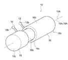
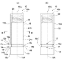
本発明の一実施形態に係る包茎矯正具10の斜視図を図1に示す。包茎矯正具10の正面図及び上面図を、図2(a)、(b)に示す。包茎矯正具10は、第1及び第2フック12、14と、第1フック12が設けられたシリンダー部材16と、第2フック14が設けられたピストン部材18と、弾性体であるコイルばね20とを備える。
FIG. 1 shows a perspective view of a
第1フック12及び第2フック14は、包茎の包皮開口部(不図示)への挿入用の一対の係合部つまり第1及び第2係合部として構成されている。第1フック12は、第2フック14と同じ形状及び寸法を有している(図1及び図2参照)。なお、第1フック12及び第2フック14は、図1及び図2(及び図6)に示すような包茎矯正具10の組み立て状態つまり使用状態において、包茎矯正具10の中心軸線10Aの方向において対向するように、シリンダー部材16及びピストン部材18のそれぞれに設けられている。
The
シリンダー部材16は、シリンダー形状、特にここでは略円筒形状を有し、中心軸線16Aを有する。シリンダー部材16の第1端部16bは有底につまり底部を有して構成され、軸線16Aの方向において第1端部16bの反対側にあるその第2端部16cは円形の開口部を区画形成する。したがって、シリンダー部材16のシリンダー壁部(円筒壁部)16d内には第2端部16cから上記ピストン部材18の一部が挿入可能である。
The
ピストン部材18は、略円柱形状を有し、中心軸線18Aを有する。ピストン部材18は、その軸線18Aの方向に延びる壁部の両端部において閉じられていて、より具体的には軸線18Aに直角にそれぞれが延びる底部を有する。図1に示すように組み立てられた包茎矯正具10において、ピストン部材18の軸線18Aはシリンダー部材16の軸線16Aつまり包茎矯正具10の中心軸線10Aに概ね一致する。ピストン部材18は、シリンダー壁部16c内に差し込み可能に形成されている差込部18bと、差込部18bよりも大径の保持部18cとを備える。差込部18bは、保持部18cと、ピストン部材18の軸線18Aに沿って並び、軸線18Aに関して同軸に一体的に形成されている。差込部18bは、シリンダー部材16のシリンダー壁部16d内にてその軸線18Aに沿って移動可能に、特に摺動可能に構成されている。具体的には、差込部18bは、シリンダー壁部16dの断面円形状に対応する断面円形状に形成されるとともに、シリンダー壁部16dの内寸法よりもわずかに小さな外寸法を有するように形成されている。保持部18cは、シリンダー部材16のシリンダー壁部16dの外寸法と同じ外寸法を有するように、かつここでは断面円形に形成されていて、シリンダー部材16の第2端部16cからシリンダー壁部16d内に差し込みできないようになっている。
The
シリンダー部材16の第2端部16cに、シリンダー壁部16dの外周面から径方向外側に突き出るように、第1フック12は一体的に設けられている。第1フック12は、シリンダー壁部16dにつながる根元部12aと、根元部12aの径方向外側につながる先端部12bとを有している。先端部12bは、根元部12aよりも太く形成されている。特にここでは先端部12bは半球状に形成されている。なお、ここでは、シリンダー部材16の第2端部16cの端面16c´に滑らかにつながりかつ平行に延びる平面部12cを、第1フック12は有する。第2端部16cの端面16c´は、軸線16Aに直角に延びる。平面部12cは根元部12aから先端部12bまで延びている。この平面部12cを除いて、第1フック12は概ね丸みを帯びた形状を有する。
The
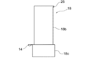
ピストン部材18の保持部18cにおける、差込部18b側の端部に、第2フック14は、保持部18cの外周面から径方向外側に突き出るように、一体的に設けられている。上で述べたように、第2フック14は第1フック12と同じ形状及び寸法を有していて、第2フック14は、上記根元部12aに対応する根元部14aと、先端部12bに対応する先端部14bと、これらにわたって延びて上記平面部12cに対応する平面部14cとを有する。なお、平面部14cは、保持部18cと差込部18bとの間に径方向に延びる円盤状の平面部18dに滑らかにかつそれに平行に延びる。平面部18dは、軸線18Aに直角に延びる。
The
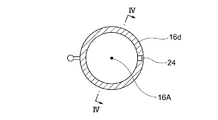
シリンダー部材16内へのピストン部材18の差込部18bの差し込み及び引き抜き動作、つまりシリンダー部材16内でのピストン部材18の差込部18bの相対移動をガイドするためのガイド部、特にここではガイド溝24が、シリンダー壁部16dの内面つまり内周面に形成されている。ガイド溝24は、図2から図4に示されている。図4に示すように、ガイド溝24は、第2端部16cに開く導入部24aと、導入部24aから周方向に所定角度ずれた位置にあるガイド主部24bと、それらをつなぐように周方向に延びる繋部24cとを備える。導入部24aと、ガイド主部24bとはそれぞれ、シリンダー部材16の軸線16Aに平行に延びるように形成されている。
A guide portion for guiding insertion and withdrawal of the
このガイド溝24に沿って案内される被ガイド部としての突起部26が、ピストン部材18の外面つまり外周面に径方向に突き出すように、ピストン部材18と一体的に設けられている(図2(a)及び図5参照)。突起部26は、シリンダー部材16に設けられたガイド溝24に沿って案内されて移動できるように形成されている。ただし、ガイド溝24には、閾値を超える力が加わっているときのみ、突起部26が乗り越えられる部分28が図4に示すように設けられている。部分28は、ガイド溝24の溝深さを浅くする隆起部として構成されていて、突起部26のガイド溝24からの意図しない逸脱を防ぐためのガイド逸脱防止機構として機能する。なお、部分28は、ここでは導入部24aに設けられているが、他の箇所に設けられてもよく、つまりガイド主部24bや繋部24cに設けられてもよく、例えば繋部24cにおけるガイド主部24b近傍の位置に設けられてもよい。
A
上記構成の包茎矯正具10の組み立てについて説明する。まず、シリンダー部材16のシリンダー壁部16d内にコイルばね20が挿入される。そして、ピストン部材18の突起部26がシリンダー部材16のガイド溝24の導入部24aに位置合わせられて、ピストン部材18の差込部18bがシリンダー部材16内に差し込まれる。この過程で、突起部26は部分28つまり隆起部28を乗り越えることが可能になり、よって、シリンダー部材16からのピストン部材18の意図しない脱落を防ぐことが可能になる。
The assembly of the
そして、突起部26がガイド溝24の導入部24aから繋部24cに移動するように、ピストン部材18はシリンダー部材16に対してその周方向に相対的に動くように捩じられる。これにより、突起部26はガイド溝24のガイド主部24bに到達できる。よって、ガイド主部24bの軸線16Aの方向の長さの範囲で、シリンダー部材16内でピストン部材18は相対移動可能になる。
Then, the
このように、シリンダー部材16内に、ピストン部材18の差込部18bが差し込まれる過程で、コイルばね20は圧縮される。このコイルばね20の圧縮に伴う復元力により、シリンダー部材16とピストン部材18とには、第1フック12と第2フック14との間隔つまり対向間隔を広げる向きの力つまり付勢力が及ぼされるようになる。なお、図2に示す包茎矯正具10では、コイルばね20はある程度圧縮状態にある。
Thus, the
このようにして組み立てられた包茎矯正具10の使用方法及び作用効果について説明する。まず、図6に示すように、シリンダー部材16内へのピストン部材18の差込部18bの差込量を増して、包茎矯正具10のその中心軸線10A方向の長さを圧縮するように、使用者はシリンダー部材16に対してピストン部材18を相対移動させる。図6では、包茎矯正具10が最大限圧縮されたところを示し、この場合、第1フック12は第2フック14に当接する。
The usage method and the effect of the
この状態で、使用者は、第1フック12及び第2フック14を包茎の包皮開口部に差し込み、それらの先端部12b、14bが包皮開口部の内側にひっかかるようにする。そして、使用者は、包茎矯正具10のその中心軸線10A方向の圧縮力を解放する。これにより、第1フック12と第2フック14との間隔を広げる向きの包茎の包皮開口部の皮を伸ばす力つまり付勢力がコイルばね20からシリンダー部材16とピストン部材18とに及ぼされる。よって、包茎矯正具10の使用中、包茎の包皮開口部には、それを押し広げる向きの包茎の包皮開口部の皮を伸ばす力が継続して作用するようになる。
In this state, the user inserts the
したがって、本発明の一実施形態に係る包茎矯正具10によれば、その使用中に、包茎の包皮が伸びたときでさえ、包皮開口部にそれを押し広げる向きにより好適な力を継続して及ぼし続けることができる。よって、包茎矯正の効果を一層高めることが可能になる。
Therefore, according to the
また、図1、図2及び図6に示す使用状態の包茎矯正具10では、ピストン部材18における突起部26が案内されるシリンダー部材16におけるガイド溝24のガイド主部24bは、シリンダー部材16の軸線16Aの方向に延びている。したがって、突起部26がガイド溝24のガイド主部24bに案内される使用時、第1フック12と第2フック14とは、周方向において互いに対してずれることが防止されて対向状態に維持され、よってそれらの軸線16Aの方向の対向間隔が狭まったり広がったりすることが好適に可能になる。よって、包茎矯正具10によれば、使用時に、コイルばね20の力で、包皮開口部を好適に広げることが可能になる。
1, 2, and 6, the guide
また、包茎矯正具10は、簡易な上記構成を有するので、その製造コストを抑制することができる。更に、簡易な構成を有するにすぎないので、包茎矯正具10は小型化に適する。例えば図6に示した状態になるので、包茎矯正具10は携帯に便利であり、専用ケース等を用いることで更にそれらの利便性の点で優れる。また、上記包茎矯正具10は、プラスチック樹脂や金属等の種々の材料で作製可能であり、その軽量化も小型化と相まって可能になる。したがって、包茎矯正具10は、使用者が容易に携帯して、種々の場所で使用することを可能にする。例えば、一日に数回(例えば朝晩の2回)、各数十分(例えば30分/回)、包茎矯正具10を使用する場合、使用者はそれを携帯し、種々の場所で所望の時期にそれを使用することが可能になる。
Moreover, since the
以上、本発明の一実施形態に係る包茎矯正具10を説明したが、本発明は上記実施形態に限定されない。例えば、上記包茎矯正具10では、第1部材はシリンダー部材16であり、第2部材はピストン部材18であり、シリンダー部材16内にピストン部材18は入れ子状にされたが、それらの一方に他方が差し込まれなくてもよい。また、シリンダー部材16内にピストン部材18のほぼ全てが差し込み可能に、シリンダー部材16及ピストン部材18が構成されてもよい。
As mentioned above, although the
また、弾性体は、コイルばね20であることに限定されず、円錐ばね、皿ばね、板ばねといった他のばねであってもよい。また複数のばねを組み合わせて、弾性体が構成されてもよい。あるいは、圧縮性流体を詰め込んだ袋体が弾性体として用いられてもよい。本発明においては、弾性体を構成するばねの種類、組み合わせ、大きさ等を任意に選択することで、そのばねの弾性力を任意に調節でき、よって包茎の包皮開口部の皮を伸ばす力を適度な力に調節することが可能になる。したがって、包茎矯正効果をより一層高めることが可能になる。
The elastic body is not limited to the
また、上記包茎矯正具10では、第1フック12が第1部材であるシリンダー部材16に一体的に設けられ、第2フック14は第2部材であるピストン部材18に一体的に設けられた。しかし、それらのフックは、それが設けられる部材に着脱自在に設けられてもよい。例えば、大きさの異なる一対のフックのセットを複数用意し、包茎の包皮開口部の大きさに応じて、使用するフックを選択するようにしてもよい。この場合、フックは種々の既知の手段又は方法により、それが設けられる部材に取り付けや取り外しがなされ得る。例えば、フックの根元部は、ねじ等の機械的接続手段によりそれが設けられる部材に着脱自在に取り付けられることができる。また、包茎矯正具10では、第1フック12と第2フック14との2つのフックが設けられたが、更に多くのフックが設けられてもよい。例えば、第1フック12を設けたシリンダー部材16に第3フックを更に設け、第2フック14を設けたピストン部材18に第4フックを更に設けてもよい。
Moreover, in the said
また、上記実施形態では、シリンダー部材にガイド部つまりガイド溝24が設けられて、ピストン部材に被ガイド部つまり突起部26が設けられた。しかし、ピストン部材にガイド部が設けられて、シリンダー部材に被ガイド部が設けられてもよい。
In the above embodiment, the cylinder member is provided with the guide portion, that is, the
以上、本発明の代表的な実施形態及び変形例について説明したが、本発明は種々の変更が可能である。本願の特許請求の範囲によって定義される本発明の精神及び範囲から逸脱しない限り、種々の置換、変更が可能である。 As mentioned above, although typical embodiment and the modification of this invention were demonstrated, this invention can be variously changed. Various substitutions and modifications may be made without departing from the spirit and scope of the present invention as defined by the claims of this application.
10 包茎矯正具
12 第1フック
14 第2フック
16 シリンダー部材
18 ピストン部材
20 コイルばね
10
Claims (5)
前記包皮開口部への挿入用の第1係合部及び第2係合部と、
該第1係合部が設けられた第1部材と、
該第1部材に対して相対移動可能に設けられて、前記第2係合部が設けられた第2部材と、
前記第1係合部と前記第2係合部との間隔を広げる向きに前記第1部材と前記第2部材とに力を及ぼすように設けられる弾性体と
を備えた、包茎矯正具。 A phimosis straightening tool for straightening and expanding the foreskin opening from the inside,
A first engaging portion and a second engaging portion for insertion into the foreskin opening,
A first member provided with the first engagement portion;
A second member provided so as to be relatively movable with respect to the first member and provided with the second engaging portion;
A phimosis corrector comprising: an elastic body provided to exert a force on the first member and the second member in a direction in which a gap between the first engagement portion and the second engagement portion is increased.
前記第2部材は前記シリンダー部材内に少なくとも部分的に差し込まれるピストン部材として構成され、
前記シリンダー部材内には、前記弾性体を圧縮するように前記ピストン部材が差し込まれている、
請求項1に記載の包茎矯正具。 The first member is configured as a cylinder member;
The second member is configured as a piston member which is at least partially inserted into the cylinder member;
In the cylinder member, the piston member is inserted so as to compress the elastic body.
The phimosis correction tool according to claim 1.
前記第1部材及び前記第2部材のいずれか他方には前記ガイド部に沿って移動可能な被ガイド部が形成されている、
請求項1又は2に記載の包茎矯正具。 A guide portion is formed on one of the first member and the second member,
A guided portion that is movable along the guide portion is formed on the other of the first member and the second member.
The phimosis correction tool according to claim 1 or 2.
前記第2係合部は前記第2部材に着脱自在に設けられている、
請求項1から4のいずれか一項に記載の包茎矯正具。
The first engaging portion is detachably provided on the first member,
The second engaging portion is detachably provided on the second member.
The phimosis correction tool according to any one of claims 1 to 4.
Priority Applications (2)
| Application Number | Priority Date | Filing Date | Title |
|---|---|---|---|
| JP2018133838A JP6436552B1 (en) | 2018-07-17 | 2018-07-17 | Uncutting tools |
| PCT/JP2019/024888 WO2020017244A1 (en) | 2018-07-17 | 2019-06-24 | Phimosis correction tool |
Applications Claiming Priority (1)
| Application Number | Priority Date | Filing Date | Title |
|---|---|---|---|
| JP2018133838A JP6436552B1 (en) | 2018-07-17 | 2018-07-17 | Uncutting tools |
Publications (2)
| Publication Number | Publication Date |
|---|---|
| JP6436552B1 true JP6436552B1 (en) | 2018-12-12 |
| JP2020010789A JP2020010789A (en) | 2020-01-23 |
Family
ID=64655896
Family Applications (1)
| Application Number | Title | Priority Date | Filing Date |
|---|---|---|---|
| JP2018133838A Active JP6436552B1 (en) | 2018-07-17 | 2018-07-17 | Uncutting tools |
Country Status (2)
| Country | Link |
|---|---|
| JP (1) | JP6436552B1 (en) |
| WO (1) | WO2020017244A1 (en) |
Families Citing this family (1)
| Publication number | Priority date | Publication date | Assignee | Title |
|---|---|---|---|---|
| JP7164911B1 (en) | 2022-04-12 | 2022-11-02 | 春一 阿部 | Phimosis correction tool and usage of phimosis correction tool |
Family Cites Families (1)
| Publication number | Priority date | Publication date | Assignee | Title |
|---|---|---|---|---|
| US20100298840A1 (en) * | 2009-05-22 | 2010-11-25 | Schwartz Lyman D | Phimosis Treatment Device and Method |
-
2018
- 2018-07-17 JP JP2018133838A patent/JP6436552B1/en active Active
-
2019
- 2019-06-24 WO PCT/JP2019/024888 patent/WO2020017244A1/en not_active Ceased
Also Published As
| Publication number | Publication date |
|---|---|
| WO2020017244A1 (en) | 2020-01-23 |
| JP2020010789A (en) | 2020-01-23 |
Similar Documents
| Publication | Publication Date | Title |
|---|---|---|
| US10709488B2 (en) | Biceps tenodesis delivery tools | |
| US9216030B2 (en) | Laparoscopic forceps assembly | |
| JP2021502855A (en) | Clip pliers | |
| JP2017051712A (en) | Human-engineering rotary tucker | |
| US20150298192A1 (en) | Bending instrument and methods of using same | |
| WO2010135056A2 (en) | Phimosis treatment device and method | |
| US20190357903A1 (en) | Side loading knot cutter | |
| WO2012173616A1 (en) | Punch tool | |
| CN109864772A (en) | Microsurgical instruments and improvements in handles | |
| JP6436552B1 (en) | Uncutting tools | |
| JP2022544973A (en) | capsular retractor | |
| KR100567588B1 (en) | Device for correcting phimosis | |
| US11439451B2 (en) | Insertion apparatus for an intramedullary nail | |
| JP7164911B1 (en) | Phimosis correction tool and usage of phimosis correction tool | |
| JP7136516B1 (en) | Phimosis correction tool and usage of phimosis correction tool | |
| TWI601510B (en) | Bendable surgical instrument for suturing meniscus | |
| JP2008142107A (en) | Phimosis corrector | |
| JPH07534A (en) | Method to embed built-in type artificial organ | |
| JP2009131450A (en) | Body traction apparatus | |
| KR101637555B1 (en) | Implant for plastic operation of virgina | |
| TWM536922U (en) | Angle-adjustable surgical instrument for sewing meniscus cartilage |
Legal Events
| Date | Code | Title | Description |
|---|---|---|---|
| A621 | Written request for application examination |
Free format text: JAPANESE INTERMEDIATE CODE: A621 Effective date: 20180717 |
|
| A871 | Explanation of circumstances concerning accelerated examination |
Free format text: JAPANESE INTERMEDIATE CODE: A871 Effective date: 20180717 |
|
| A975 | Report on accelerated examination |
Free format text: JAPANESE INTERMEDIATE CODE: A971005 Effective date: 20181005 |
|
| A131 | Notification of reasons for refusal |
Free format text: JAPANESE INTERMEDIATE CODE: A131 Effective date: 20181015 |
|
| A521 | Written amendment |
Free format text: JAPANESE INTERMEDIATE CODE: A523 Effective date: 20181030 |
|
| TRDD | Decision of grant or rejection written | ||
| A01 | Written decision to grant a patent or to grant a registration (utility model) |
Free format text: JAPANESE INTERMEDIATE CODE: A01 Effective date: 20181107 |
|
| A61 | First payment of annual fees (during grant procedure) |
Free format text: JAPANESE INTERMEDIATE CODE: A61 Effective date: 20181109 |
|
| R150 | Certificate of patent or registration of utility model |
Ref document number: 6436552 Country of ref document: JP Free format text: JAPANESE INTERMEDIATE CODE: R150 |
|
| S531 | Written request for registration of change of domicile |
Free format text: JAPANESE INTERMEDIATE CODE: R313531 |
|
| R350 | Written notification of registration of transfer |
Free format text: JAPANESE INTERMEDIATE CODE: R350 |
|
| R250 | Receipt of annual fees |
Free format text: JAPANESE INTERMEDIATE CODE: R250 |