JP6435112B2 - Spinning molding equipment - Google Patents
Spinning molding equipment Download PDFInfo
- Publication number
- JP6435112B2 JP6435112B2 JP2014080696A JP2014080696A JP6435112B2 JP 6435112 B2 JP6435112 B2 JP 6435112B2 JP 2014080696 A JP2014080696 A JP 2014080696A JP 2014080696 A JP2014080696 A JP 2014080696A JP 6435112 B2 JP6435112 B2 JP 6435112B2
- Authority
- JP
- Japan
- Prior art keywords
- heater
- plate material
- rotating shaft
- processing tool
- molding apparatus
- Prior art date
- Legal status (The legal status is an assumption and is not a legal conclusion. Google has not performed a legal analysis and makes no representation as to the accuracy of the status listed.)
- Active
Links
Images


Classifications
-
- B—PERFORMING OPERATIONS; TRANSPORTING
- B21—MECHANICAL METAL-WORKING WITHOUT ESSENTIALLY REMOVING MATERIAL; PUNCHING METAL
- B21D—WORKING OR PROCESSING OF SHEET METAL OR METAL TUBES, RODS OR PROFILES WITHOUT ESSENTIALLY REMOVING MATERIAL; PUNCHING METAL
- B21D22/00—Shaping without cutting, by stamping, spinning, or deep-drawing
- B21D22/14—Spinning
- B21D22/18—Spinning using tools guided to produce the required profile
-
- B—PERFORMING OPERATIONS; TRANSPORTING
- B21—MECHANICAL METAL-WORKING WITHOUT ESSENTIALLY REMOVING MATERIAL; PUNCHING METAL
- B21D—WORKING OR PROCESSING OF SHEET METAL OR METAL TUBES, RODS OR PROFILES WITHOUT ESSENTIALLY REMOVING MATERIAL; PUNCHING METAL
- B21D22/00—Shaping without cutting, by stamping, spinning, or deep-drawing
- B21D22/14—Spinning
-
- B—PERFORMING OPERATIONS; TRANSPORTING
- B21—MECHANICAL METAL-WORKING WITHOUT ESSENTIALLY REMOVING MATERIAL; PUNCHING METAL
- B21D—WORKING OR PROCESSING OF SHEET METAL OR METAL TUBES, RODS OR PROFILES WITHOUT ESSENTIALLY REMOVING MATERIAL; PUNCHING METAL
- B21D37/00—Tools as parts of machines covered by this subclass
- B21D37/16—Heating or cooling
Landscapes
- Engineering & Computer Science (AREA)
- Mechanical Engineering (AREA)
- Shaping Metal By Deep-Drawing, Or The Like (AREA)
- Mounting, Exchange, And Manufacturing Of Dies (AREA)
Description
本発明は、板材を回転させながら所望の形状に成形するスピニング成形装置に関する。 The present invention relates to a spinning molding apparatus that molds a plate material into a desired shape while rotating the plate material.
従来から、板材を回転させながらその板材に加工具を押圧して当該板材を変形させるスピニング成形装置が知られている。このようなスピニング成形装置は通常は回転シャフトに取り付けられたマンドレル(成形型)を有し、板材が加工具によってマンドレルに押し付けられることにより成形が行われる。 2. Description of the Related Art Conventionally, there is known a spinning molding apparatus that deforms a plate by pressing a processing tool against the plate while rotating the plate. Such a spinning molding apparatus usually has a mandrel (molding die) attached to a rotating shaft, and molding is performed by pressing a plate material against the mandrel by a processing tool.
近年では、板材を局所的に加熱しながらスピニング成形を行うスピニング成形装置が提案されている。例えば、特許文献1には、チタン合金用のスピニング成形装置として、板材におけるヘラ(加工具)によってマンドレルに押し付けられる部位(変形対象部位)を高周波誘導加熱により加熱するスピニング成形装置が開示されている。
In recent years, a spinning molding apparatus that performs spinning molding while locally heating a plate material has been proposed. For example,
ところで、本発明の発明者らは、スピニング成形装置に好適な加熱器として、板材の回転方向に延びる、板材に沿った二重円弧状のコイル部を有する加熱器を以前に開発した(特許文献2参照)。このような加熱器を用いれば、板材における変形対象部位の局所的な加熱を板材の回転方向に連続的に行うことができ、良好な成形を実現することができる。 By the way, the inventors of the present invention have previously developed a heater having a double arc-shaped coil portion along a plate material that extends in the rotation direction of the plate material as a heater suitable for a spinning molding apparatus (Patent Literature). 2). If such a heater is used, the local heating of the deformation target part in the plate material can be continuously performed in the rotation direction of the plate material, and good molding can be realized.
本発明の発明者らは、最近の研究において、変形対象部位に加工具を押圧すると、変形対象部位を含む外周側原形部が傾くことがあることを新たに発見した。しかしながら、上述した二重円弧状のコイル部を有する加熱器ではコイル部が板材と平行であるために、外周側原形部が傾くと、コイル部から外周側原形部までの距離が不均一となり、加熱器による加熱が不十分になったり、場合によっては傾いた外周側原形部が加熱器のコイル部に接触したりするおそれがある。 In recent studies, the inventors of the present invention have newly discovered that when a processing tool is pressed against a deformation target part, the outer peripheral side original shape part including the deformation target part may be inclined. However, in the heater having the above-described double arc-shaped coil part, since the coil part is parallel to the plate material, when the outer peripheral side original part is inclined, the distance from the coil part to the outer peripheral original part is non-uniform, There is a possibility that heating by the heater may be insufficient, or in some cases, the inclined outer peripheral original shape portion may contact the coil portion of the heater.
そこで、本発明は、板材の外周側原形部が傾いても外周側原形部と加熱器のコイル部との位置関係を適切に保つことができるスピニング成形装置を提供することを目的とする。 Then, an object of this invention is to provide the spinning shaping | molding apparatus which can maintain the positional relationship of an outer peripheral side original shape part and the coil part of a heater appropriately even if the outer peripheral side original shape part of a board | plate material inclines.
前記課題を解決するために、本発明のスピニング成形装置は、成形されるべき板材を回転させる回転シャフトと、前記板材における変形対象部位を押圧して前記板材を変形させる加工具と、前記変形対象部位を誘導加熱により局所的に加熱する加熱器であって、前記回転シャフトの周方向に延びる、前記板材に沿った二重円弧状のコイル部を含む加熱器と、前記回転シャフトの周方向に分布する複数の計測点で、前記コイル部から、前記板材における前記変形対象部位を含む外周側原形部までの距離を計測する計測器と、前記回転シャフトから前記加工具に向かう方向に対して前記加熱器を傾斜させる傾斜装置と、前記コイル部と前記外周側原形部との角度差が所定角度以内となるように前記計測器の計測結果に基づいて前記傾斜装置を制御する制御装置と、を備える、ことを特徴とする。 In order to solve the above problems, a spinning molding apparatus of the present invention includes a rotating shaft that rotates a plate material to be molded, a processing tool that deforms the plate material by pressing a deformation target portion of the plate material, and the deformation target. A heater that locally heats a part by induction heating, the heater including a double arc-shaped coil portion along the plate extending in the circumferential direction of the rotating shaft, and in the circumferential direction of the rotating shaft A measuring instrument that measures the distance from the coil part to the outer peripheral side original part including the deformation target part in the plate material at a plurality of distributed measurement points, and the direction from the rotary shaft toward the processing tool The tilting device is controlled based on the measurement result of the measuring instrument so that the angle difference between the tilting device for tilting the heater and the coil portion and the outer peripheral side original shape portion is within a predetermined angle. And a control unit that, the, characterized in that.
上記の構成によれば、加熱器のコイル部から板材の外周側原形部までの距離をほぼ均一に保つことができる。その結果、外周側原形部が傾いても外周側原形部とコイル部との位置関係を適切に保つことができる。 According to said structure, the distance from the coil part of a heater to the outer peripheral side original shape part of a board | plate material can be kept substantially uniform. As a result, even if the outer peripheral side original shape portion is inclined, the positional relationship between the outer peripheral side original shape portion and the coil portion can be appropriately maintained.
例えば、前記加熱器は、前記回転シャフトを挟んで前記加工具の真向かいの位置からずれた位置に配置されており、前記傾斜装置は、前記回転シャフトの径方向に延びる揺動軸回りに前記加熱器を揺動させてもよい。 For example, the heater is disposed at a position deviated from a position directly opposite to the processing tool across the rotating shaft, and the tilting device is arranged around the swing axis extending in the radial direction of the rotating shaft. The vessel may be swung.
例えば、前記加熱器は、前記回転シャフトを挟んで前記加工具の真向かいの位置に配置されており、前記傾斜装置は、前記回転シャフトの径方向と直交する方向に延びる揺動軸回りに前記加熱器を揺動させてもよい。 For example, the heater is disposed at a position directly opposite to the processing tool with the rotary shaft interposed therebetween, and the tilting device is configured to rotate the heating device around an oscillation shaft extending in a direction perpendicular to the radial direction of the rotary shaft. The vessel may be swung.
例えば、前記制御装置は、前記複数の計測点で計測される距離間の差の絶対値が閾値以下となるように前記傾斜装置を制御してもよい。 For example, the control device may control the tilting device so that an absolute value of a difference between distances measured at the plurality of measurement points is equal to or less than a threshold value.
例えば、前記計測器は、前記回転シャフトの周方向に互いに離間するように配置された複数の距離センサを含んでもよい。 For example, the measuring instrument may include a plurality of distance sensors arranged so as to be separated from each other in the circumferential direction of the rotating shaft.
例えば、前記加熱器は、前記板材を挟んで前記加工具と反対側に配置された裏側加熱器と、前記板材に対して前記加工具と同じ側に配置された表側加熱器の少なくとも一方であってもよい。 For example, the heater may be at least one of a back side heater disposed on the opposite side of the processing tool across the plate material and a front side heater disposed on the same side as the processing tool with respect to the plate material. May be.
上記のスピニング成形装置は、前記加熱器が連結された、内部に交流電源回路が形成されたヒートステーションをさらに備え、前記傾斜装置は、前記ヒートステーションを介して前記加熱器を傾斜させてもよい。この構成によれば、加熱器がヒートステーションとともに傾斜させられるため、ヒートステーションで加熱器を強固に保持することができる。その結果、加熱器のコイル部に大電流が流れて加熱器に大きな引力および斥力が作用したとしても、加熱器の変形を抑制することができる。 The spinning molding apparatus may further include a heat station having an AC power supply circuit formed therein, to which the heater is connected, and the tilting device may tilt the heater via the heat station. . According to this configuration, since the heater is inclined together with the heat station, the heater can be firmly held in the heat station. As a result, even if a large current flows through the coil portion of the heater and a large attractive force and repulsive force act on the heater, deformation of the heater can be suppressed.
上記のスピニング成形装置は、前記回転軸に取り付けられた、前記板材の中心部を支持する受け治具をさらに備えてもよい。例えば、マンドレルを用いた場合には、板材の外周側原形部の傾きは、主に板材の弾性変形に起因すると推測される。これに対し、マンドレルの代わりに受け治具を用いた場合には、板材における受け治具からの張り出し部分(受け治具で支持される中心部以外の部分)が片持ち梁となっているために、板材の外周側原形部の傾きが、張り出し部分の撓みによってさらに大きくなる。従って、このような受け治具を用いた場合には、本発明の効果を顕著に得ることができる。 Said spinning shaping | molding apparatus may further be equipped with the receiving jig which supports the center part of the said board | plate material attached to the said rotating shaft. For example, when a mandrel is used, it is estimated that the inclination of the outer peripheral side original shape portion of the plate material is mainly caused by elastic deformation of the plate material. On the other hand, when a receiving jig is used instead of the mandrel, the projecting part of the plate material from the receiving jig (the part other than the center part supported by the receiving jig) is a cantilever. Further, the inclination of the outer peripheral side original shape portion of the plate material is further increased by the bending of the overhanging portion. Therefore, when such a receiving jig is used, the effect of the present invention can be remarkably obtained.
本発明によれば、板材の外周側原形部が傾いても外周側原形部と加熱器のコイル部との位置関係を適切に保つことができる。 According to this invention, even if the outer peripheral side original shape part of a board | plate material inclines, the positional relationship of an outer peripheral side original shape part and the coil part of a heater can be maintained appropriately.
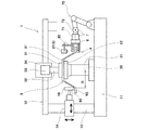
図1に、本発明の一実施形態に係るスピニング成形装置1を示す。このスピニング成形装置1は、成形されるべき板材9を回転させる回転シャフト21と、回転シャフト21と板材9の間に介在する受け治具22と、固定治具31を備えている。受け治具22は、回転シャフト21に取り付けられて板材9の中心部91を支持し、固定治具31は、受け治具22と共に板材9を挟持する。さらに、スピニング成形装置1は、板材9における回転シャフト21の軸心20から所定距離Rだけ離れた変形対象部位92を誘導加熱により局所的に加熱する裏側加熱器4および表側加熱器5と、変形対象部位92を押圧して板材9を変形させる加工具10を備えている。
FIG. 1 shows a spinning
回転シャフト21の軸方向(軸心20が延びる方向)は、本実施形態では鉛直方向である。ただし、回転シャフト21の軸方向は、水平方向や斜め方向であってもよい。回転シャフト21の下部は基台11に支持されており、回転シャフト21は図略のモータによって回転させられる。回転シャフト21の上面はフラットであり、この上面に受け治具22が固定されている。
The axial direction of the rotating shaft 21 (the direction in which the
板材9は、例えばフラットな円形状の板である。ただし、板材9の形状は、多角形状や楕円状であってもよい。また、板材9は、必ずしも全面に亘ってフラットである必要はなく、例えば中心部91の厚さが周縁部の厚さよりも厚かったり、全体または一部が予めテーパー状に加工されたりしてもよい。板材9の材質は、特に限定されるものではないが、例えばチタン合金である。
The
受け治具22は、板材9における成形開始位置によって規定される円に収まるサイズを有している。例えば、受け治具22が円盤状である場合は、受け治具22の直径は、板材9における成形開始位置によって規定される円の直径以下である。また、従来のマンドレルと異なり、板材9は、受け治具22の径方向外向きの側面に押し付けられて変形されることはない。
The receiving
固定治具31は、加圧ロッド32に取り付けられており、加圧ロッド32は、支持部33によって回転可能に支持されている。支持部33は、駆動部34によって上下方向に駆動される。駆動部34は、回転シャフト21の上方に配置されたフレーム12に取り付けられている。ただし、固定治具31を省略し、例えばボルトによって板材9を受け治具22に直接的に固定してもよい。
The
本実施形態では、板材9の変形対象部位92を押圧する加工具10が板材9の上方に配置され、加工具10によって板材9が受け治具22を収容するような下向きに開口する形状に加工される。すなわち、板材9の上面が表面であり、板材9の下面が裏面である。ただし、加工具10が板材9の下方に配置され、加工具10によって板材9が固定治具31を収容するような上向きに開口する形状に加工されてもよい。すなわち、板材9の下面が表面であり、板材9の上面が裏面であってもよい。
In this embodiment, the
加工具10は、第1径方向移動機構14により回転シャフト21の径方向に移動させられるとともに、第1軸方向移動機構13により径方向移動機構14を介して回転シャフト21の軸方向に移動させられる。第1軸方向移動機構13は、上述した基台11とフレーム12を橋架するように延びている。本実施形態では、加工具10として、板材9の回転に追従して回転するローラが用いられている。ただし、加工具10は、ローラに限定されず、例えばヘラであってもよい。
The
裏側加熱器4は、板材9を挟んで加工具10と反対側に配置されており、表側加熱器5は、板材9に対して加工具10と同じ側に配置されている。本実施形態では、裏側加熱器4および表側加熱器5が同一のヒートステーション6に連結されている。裏側加熱器4および表側加熱器5は、回転シャフト21の軸方向で互いに対向しており、ヒートステーション6は、回転シャフト21の径方向において加熱器4,5の外側に配置されている。
The back heater 4 is disposed on the opposite side of the
裏側加熱器4および表側加熱器5は、第2径方向移動機構16によりヒートステーション6を介して回転シャフト21の径方向に移動させられるとともに、第2軸方向移動機構15によりヒートステーション6および径方向移動機構16を介して回転シャフト21の軸方向に移動させられる。第2軸方向移動機構15は、上述した基台11とフレーム12を橋架するように延びている。
The back side heater 4 and the front side heater 5 are moved in the radial direction of the
ヒートステーション6は、図3〜図5に示すように、箱状の本体60と、本体60における回転シャフト21に対向する側面に固定された一対の接続箱61,62を含む。本体60の内部には、後述する裏側加熱器4の電通管41および表側加熱器5の電通管51に電圧を印加するための交流電源回路が形成されている。接続箱61,62は、導電性の部材からなり、絶縁板65を挟んで互いに隣接している。接続箱61,62のそれぞれは、本体60内の電源回路と電気的に接続されている。本実施形態では、接続箱61,62が、表側加熱器5と裏側加熱器4に跨るように鉛直方向に延びている。
As shown in FIGS. 3 to 5, the
接続箱61,62同士は、後述する裏側加熱器4の電通管41および表側加熱器5の電通管51を介して電気的に接続される。すなわち、接続箱61,62の一方から他方へ、電通管51,41を通じて交流電流が流される。交流電流の周波数は、特に限定されるものではないが、5k〜400kHzの高周波数であることが望ましい。すなわち、裏側加熱器4および表側加熱器5による誘導加熱は、高周波誘導加熱であることが望ましい。
The
また、接続箱61,62には、冷却液ポート63,64がそれぞれ設けられている。そして、接続箱61,62の一方の内部には冷却液ポート(63または64)を通じて冷却液が供給され、この冷却液が後述する電通管51,41を循環した後に、接続箱61,62の他方の内部から冷却液ポート(64または63)を通じて排出される。このような電通管51,41を通じた冷却液の循環により、電通管51,41に大電流(例えば、1000〜4000A)を流すことが可能となっている。
The
裏側加熱器4は、図3および図5に示すように、内部に冷却液が流れる電通管41と、支持板40を含む。電通管41の断面形状は、本実施形態では正方形状であるが、その他の形状(例えば、円形状)であってもよい。支持板40は、例えば、耐熱性の材料(例えば、セラミック繊維系材料)からなり、図略の絶縁部材を介して電通管41を支持する。また、支持板40は、図略の絶縁部材を介してヒートステーション6の本体60に固定される。なお、支持板40を絶縁性の樹脂で構成することも可能である。この場合は、支持板40が電通管41を直接的に支持していてもよいし、ヒートステーション6の本体60に直接的に固定されてもよい。
As shown in FIGS. 3 and 5, the backside heater 4 includes a
電通管41は、回転シャフト21の周方向に延びる、板材9に沿った二重円弧状のコイル部44と、コイル部44の中央から回転シャフト21の径方向外向きに延びる一対のリード部42,43を有する。すなわち、コイル部44は、1つの内側円弧部45と、リード部42,43の両側に広がる2つの外側円弧部46を含む。コイル部44の開き角度(両端部間の角度)は、例えば60〜120度である。一対のリード部42,43は、ヒートステーション6の接続箱61,62につながっている。
The
また、裏側加熱器4は、コイル部44の内側円弧部45を板材9と反対側から覆う1つの第1コア47と、外側円弧部46を板材9と反対側から覆う2つの第2コア48を含む。第1コア47および第2コア48は、内側円弧部45および外側円弧部46の周囲に発生する磁束を集約するためのものである。第1コア47および第2コア48は、図略の絶縁部材を介して支持板40に支持されている。
The back heater 4 includes one
表側加熱器5は、図3および図4に示すように、内部に冷却液が流れる電通管51と、支持板50を含む。電通管51の断面形状は、本実施形態では正方形状であるが、その他の形状(例えば、円形状)であってもよい。支持板50は、例えば、耐熱性の材料(例えば、セラミック繊維系材料)からなり、図略の絶縁部材を介して電通管51を支持する。また、支持板50は、図略の絶縁部材を介してヒートステーション6の本体60に固定される。なお、支持板50を絶縁性の樹脂で構成することも可能である。この場合は、支持板50が電通管51を直接的に支持していてもよいし、支持板50がヒートステーション6の本体60に直接的に固定されてもよい。
As shown in FIGS. 3 and 4, the front-side heater 5 includes a
電通管51は、回転シャフト21の周方向に延びる、板材9に沿った二重円弧状のコイル部54と、コイル部54の中央から回転シャフト21の径方向外向きに延びる一対のリード部52,53を有する。すなわち、コイル部54は、1つの内側円弧部55と、リード部52,53の両側に広がる2つの外側円弧部56を含む。コイル部54の開き角度(両端部間の角度)は、例えば60〜120度である。一対のリード部52,53は、ヒートステーション6の接続箱61,62につながっている。すなわち、表側加熱器5の電通管51は、接続箱61,62に対し、裏側加熱器4の電通管41と並列に接続されている。ただし、電通管51が電通管41と直列に接続されていてもよい。
The
また、表側加熱器5は、コイル部54の内側円弧部55を板材9と反対側から覆う1つの第1コア57と、外側円弧部56を板材9と反対側から覆う2つの第2コア58を含む。第1コア57および第2コア58は、内側円弧部55および外側円弧部56の周囲に発生する磁束を集約するためのものである。第1コア57および第2コア58は、図略の絶縁部材を介して支持板50に支持されている。
The front heater 5 includes one
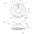
加熱器4,5と加工具10との相対位置は、それらが回転シャフト21の軸心20を中心とするほぼ同一円周上に位置している限り、特に限定されるものではない。本実施形態では、図6(a)に示すように、裏側加熱器4および表側加熱器5は、回転シャフト21を挟んで加工具10の真向かいの位置からずれた位置(例えば、回転シャフト21の軸心20から見たときの裏側加熱器4および表側加熱器5の中心と加工具10の中心との間の角度が約120度となる位置)に配置されている。なお、図1では、スピニング成形装置1の構成を分かり易く示すために、加熱器4,5を回転シャフト21を挟んで加工具10の真向かいの位置に描いているが、加熱器4,5の正しい位置は図6(a)に示す通りである。
The relative positions of the heaters 4 and 5 and the
図1に戻って、裏側加熱器4および表側加熱器5が連結されたヒートステーション6と第2径方向移動機構16の間には、ヒートステーション6を介して加熱器4,5を傾斜させる傾斜装置7が設けられている。傾斜装置7は、回転シャフト21から加工具10に向かう方向Dに対して加熱器4,5を傾斜させる。
Returning to FIG. 1, between the
より詳しくは、加熱器4,5と加工具10の相対位置関係は図6(a)に示す通りであるため、傾斜装置7は、回転シャフト21の径方向に延びる揺動軸71回りに加熱器4,5を揺動させる。揺動軸71は、例えば、ヒートステーション6の中心線と一致する。傾斜装置7としては、例えば、ロータリテーブルを用いることができる。
More specifically, since the relative positional relationship between the heaters 4 and 5 and the
加工具10用の移動機構13,14および加熱器4,5用の移動機構15,16ならびに傾斜装置7は、図2に示す制御装置17により制御される。制御装置17には、板材9を所望の形状に成形するためのプログラムが予め格納されており、制御装置17は、そのプログラムに従って移動機構13,14を制御して加工具10を操作する。
The moving
本実施形態では、図3および図4に示すように、表側加熱器5に、板材9の変形対象部位92までの距離を計測する2つの距離センサ81がブラケット85により取り付けられている。2つの距離センサ81は、回転シャフト21の周方向に互いに離間して配置されている。そして、制御装置17は、加工具10を操作すると同時に、距離センサ81で計測される距離が一定となるように、移動機構15,16を制御して加熱器4,5を加工具10に追従して移動させる。なお、距離センサ81は、裏側加熱器4に取り付けられていてもよい。
In the present embodiment, as shown in FIGS. 3 and 4, two
より詳しくは、距離センサ81は、平面視で、コイル部54の中心線上にコイル部54を挟むように配置されている。ブラケット85は、支持板50上に立てられた支柱86と、支柱86から距離センサ81まで延びるアーム87を含む。
More specifically, the
上述した構成により、距離センサ81とコイル部54との相対位置は不変である。すなわち、距離センサ81は、回転シャフト21の周方向に分布する複数(本実施形態では2つ)の計測点で、コイル部54から板材9における変形対象部位92を含む外周側原形部93までの距離を計測する計測器8としても機能する。
With the above-described configuration, the relative position between the
そして、上述した制御装置17は、距離センサ81の計測結果に基づいて、コイル部54と外周側原形部93との角度差が所定角度(例えば、5度)以内となるように、傾斜装置7を制御する。具体的には、制御装置17は、複数の計測点で計測される距離間の差の絶対値が閾値以下となるように、傾斜装置7を制御する。例えば、一方の距離センサ81で計測されるコイル部54の一端から外周側原形部93までの距離をA、他方の距離センサ81で計測されるコイル部54の他端から外周側原形部93までの距離をB、閾値をαとすると、制御装置17は以下の式を満たすように傾斜装置7を制御する。
|A−B|≦α
And the
| A-B | ≦ α
ただし、計測器8は、必ずしも複数の距離センサ81で構成されている必要はない。例えば、計測器8としてカメラおよび画像処理装置を含む撮像システムを用い、画像処理によって複数の計測点での距離を計測してもよい。
However, the measuring
以上説明したように、本実施形態のスピニング成形装置1では、加熱器4,5のコイル部44,54から板材9の外周側原形部93までの距離をほぼ均一に保つことができる。その結果、図6(b)に示すように外周側原形部93が傾いても外周側原形部93とコイル部44,54との位置関係を適切に保つことができる。
As described above, in the
(その他の実施形態)
本発明は上述した実施形態に限定されるものではなく、本発明の要旨を逸脱しない範囲で種々の変形が可能である。
(Other embodiments)
The present invention is not limited to the above-described embodiments, and various modifications can be made without departing from the gist of the present invention.
例えば、図7(a)および(b)に示すように、裏側加熱器4および表側加熱器5は、回転シャフト21を挟んで加工具10の真向かいの位置に配置されていてもよい(図7(a)および(b)では加熱器4,5のコイル部44,54のみを図示)。この場合、傾斜装置7は、回転シャフト21の径方向と直交する方向に延びる揺動軸72回りに加熱器4,5を揺動させることによって、回転シャフト21から加工具10に向かう方向に対して加熱器4,5を傾斜させてもよい。
For example, as shown in FIGS. 7A and 7B, the back-side heater 4 and the front-side heater 5 may be disposed at a position directly opposite the
図7(a)および(b)に示すレイアウトの場合、例えば、3つの距離センサ81が、コイル部54の両端から外周側原形部93までの距離とコイル部54の中央から外周側原形部93までの距離を計測できるように配置される。
In the layout shown in FIGS. 7A and 7B, for example, the three
また、傾斜装置7は、図8に示すように多軸ロボット75の一軸を構成していてもよい。例えば、加熱器4,5が回転シャフト21を挟んで加工具10の真向かいの位置からずれた位置に配置される場合、傾斜装置7として、多軸ロボット75の第1(先端)アームとヒートステーション6の間に揺動軸71回りに加熱器4,5を揺動させる回動機構が採用される。あるいは、加熱器4,5が回転シャフト21を挟んで加工具10の真向かいの位置に配置される場合、傾斜装置7として、多軸ロボット75の第1アームと第2アームの間に揺動軸72回りに加熱器4,5を揺動させる回動機構が採用される。この場合、第1アームとヒートステーション6の間の回動機構は不要である。
The
さらに、スピニング成形装置1には、必ずしも裏側加熱器4と表側加熱器5の双方が設けられている必要はなく、どちらか一方だけが用いられていてもよい。すなわち、本発明の加熱器は、裏側加熱器4と表側加熱器5の少なくとも一方であればよい。
Furthermore, the spinning
また、傾斜装置7は、必ずしもヒートステーション6を介して裏側加熱器4と表側加熱器5の少なくとも一方を傾斜させる必要はない。例えば、傾斜装置7は、裏側加熱器4および表側加熱器5を個別に傾斜できるように、裏側加熱器4および表側加熱器5のそれぞれとヒートステーション6の間に配置されていてもよい。この場合、傾斜装置7は、加熱器(4または5)の支持板(40または50)を揺動可能に支持する支持部と、支持板を駆動するアクチュエータ(例えば、電動シリンダ)とで構成されていてもよい。
Further, the
さらには、前記実施形態では受け治具22が用いられていたが、受け治具22の代わりに、マンドレルが採用されていてもよい。マンドレルを用いた場合には、加工具10によって板材9の変形対象部位92がマンドレルに押し付けられるため、外周側原形部93の傾きが小さくなる。これに対し、受け治具22を用いた場合には、板材9の変形対象部位92が、受け治具22から離れた空中で加工具10によって押圧されるため、外周側原形部93の傾きが大きくなる。それ故に、受け治具22を具備するスピニング成形装置1であれば、本発明の効果を顕著に得ることができる。
Furthermore, although the receiving
本発明は、種々の素材からなる板材をスピニング成形する際に有用である。 The present invention is useful when spinning a plate made of various materials.
1 スピニング成形装置
10 加工具
17 制御装置
21 回転シャフト
22 受け治具
4 裏側加熱器
5 表側加熱器
42,52 コイル部
6 ヒートステーション
7 傾斜装置
8 計測器
81 距離センサ
9 板材
91 中心部
92 変形対象部位
93 外周側原形部
DESCRIPTION OF
Claims (8)
前記板材における変形対象部位を押圧して前記板材を変形させる加工具と、
前記変形対象部位を誘導加熱により局所的に加熱する加熱器であって、前記回転シャフトの周方向に延びる、前記板材に沿った二重円弧状のコイル部を含む加熱器と、
前記コイル部の中心線上に配置された、前記回転シャフトの周方向に分布する複数の計測点で、前記コイル部から、前記板材における前記変形対象部位を含む外周側原形部までの距離を計測する計測器と、
前記回転シャフトから前記加工具に向かう方向に対して前記加熱器を傾斜させる傾斜装置と、
前記コイル部と前記外周側原形部との角度差が所定角度以内となるように前記計測器の計測結果に基づいて前記傾斜装置を制御する制御装置と、
を備える、スピニング成形装置。 A rotating shaft for rotating the plate material to be formed;
A processing tool for deforming the plate material by pressing a deformation target portion in the plate material;
A heater that locally heats the deformation target portion by induction heating, the heater including a double arc-shaped coil portion extending along the circumferential direction of the rotating shaft,
The distance from the coil portion to the outer peripheral side original shape portion including the deformation target portion in the plate material is measured at a plurality of measurement points arranged on the center line of the coil portion and distributed in the circumferential direction of the rotating shaft. Measuring instruments,
A tilting device for tilting the heater with respect to a direction from the rotating shaft toward the processing tool;
A control device for controlling the tilting device based on a measurement result of the measuring instrument such that an angle difference between the coil portion and the outer peripheral side original shape portion is within a predetermined angle;
A spinning molding apparatus.
前記傾斜装置は、前記回転シャフトの径方向に延びる揺動軸回りに前記加熱器を揺動させる、請求項1に記載のスピニング成形装置。 The heater is disposed at a position shifted from a position directly opposite the processing tool across the rotating shaft,
The spinning molding apparatus according to claim 1, wherein the tilting device swings the heater around a swing shaft extending in a radial direction of the rotating shaft.
前記傾斜装置は、前記回転シャフトの径方向と直交する方向に延びる揺動軸回りに前記加熱器を揺動させる、請求項1に記載のスピニング成形装置。 The heater is disposed at a position directly opposite the processing tool across the rotating shaft,
The spinning molding apparatus according to claim 1, wherein the tilting device swings the heater around a swing shaft extending in a direction orthogonal to a radial direction of the rotating shaft.
前記傾斜装置は、前記ヒートステーションを介して前記加熱器を傾斜させる、請求項1〜6のいずれか一項に記載のスピニング成形装置。 The heater is further connected, further comprising a heat station in which an AC power supply circuit is formed,
The spinning molding apparatus according to any one of claims 1 to 6, wherein the tilting device tilts the heater via the heat station.
Priority Applications (5)
| Application Number | Priority Date | Filing Date | Title |
|---|---|---|---|
| JP2014080696A JP6435112B2 (en) | 2014-04-10 | 2014-04-10 | Spinning molding equipment |
| US15/303,253 US10259029B2 (en) | 2014-04-10 | 2015-04-03 | Spinning forming device |
| PCT/JP2015/001905 WO2015155970A1 (en) | 2014-04-10 | 2015-04-03 | Spinning forming device |
| CN201580010554.2A CN106029247A (en) | 2014-04-10 | 2015-04-03 | Spinning forming device |
| EP15776232.9A EP3130411B1 (en) | 2014-04-10 | 2015-04-03 | Spinning forming device |
Applications Claiming Priority (1)
| Application Number | Priority Date | Filing Date | Title |
|---|---|---|---|
| JP2014080696A JP6435112B2 (en) | 2014-04-10 | 2014-04-10 | Spinning molding equipment |
Publications (3)
| Publication Number | Publication Date |
|---|---|
| JP2015199103A JP2015199103A (en) | 2015-11-12 |
| JP2015199103A5 JP2015199103A5 (en) | 2017-04-06 |
| JP6435112B2 true JP6435112B2 (en) | 2018-12-05 |
Family
ID=54287556
Family Applications (1)
| Application Number | Title | Priority Date | Filing Date |
|---|---|---|---|
| JP2014080696A Active JP6435112B2 (en) | 2014-04-10 | 2014-04-10 | Spinning molding equipment |
Country Status (5)
| Country | Link |
|---|---|
| US (1) | US10259029B2 (en) |
| EP (1) | EP3130411B1 (en) |
| JP (1) | JP6435112B2 (en) |
| CN (1) | CN106029247A (en) |
| WO (1) | WO2015155970A1 (en) |
Families Citing this family (6)
| Publication number | Priority date | Publication date | Assignee | Title |
|---|---|---|---|---|
| CN106734646B (en) * | 2016-11-29 | 2018-10-09 | 广东工业大学 | A kind of hull complexity outside plate processing firelock head verticality keeping method and device |
| CN106964682B (en) * | 2017-03-28 | 2019-01-15 | 华南理工大学 | A kind of high warm power spinning heating means and device |
| CN107649562A (en) * | 2017-10-01 | 2018-02-02 | 深圳市普耐光电科技有限公司 | A kind of spinning machine |
| CN109954782A (en) * | 2018-01-09 | 2019-07-02 | 南京航空航天大学 | Synchronous heating forming spinning device and method for local self-resistance electric heat generation of plate |
| PL3941157T3 (en) * | 2020-07-15 | 2025-12-22 | Abp Induction Systems Gmbh | Method and system for inductively heating flat articles |
| CN113305213B (en) * | 2021-05-27 | 2022-08-16 | 肇庆怀集金业五金有限公司 | Manufacturing equipment for central gas distribution disc of stainless steel intelligent gas stove and working method of manufacturing equipment |
Family Cites Families (11)
| Publication number | Priority date | Publication date | Assignee | Title |
|---|---|---|---|---|
| DE4425033C2 (en) * | 1994-07-15 | 1999-07-29 | Fraunhofer Ges Forschung | Method and device for press forming workpieces |
| CN101875075B (en) * | 2009-04-28 | 2012-08-29 | 陈万忠 | Cold and hot spinning machine and hot spinning method |
| JP2011198730A (en) * | 2010-03-24 | 2011-10-06 | Tokyo Electric Power Co Inc:The | Movable heating system |
| JP5913792B2 (en) * | 2010-04-13 | 2016-04-27 | 一般社団法人日本航空宇宙工業会 | Molding method and molding apparatus |
| JP5520761B2 (en) * | 2010-09-22 | 2014-06-11 | 株式会社Ihi | Heating head, heating head control method, and heating head control program |
| CN101972808B (en) * | 2010-10-18 | 2012-02-22 | 哈尔滨工业大学 | Independent digital flame following and heating device of hot spinning machine |
| CN102601198A (en) * | 2012-03-26 | 2012-07-25 | 苏州先端稀有金属有限公司 | Spin forming device for molybdenum plate |
| CN104487185B (en) * | 2012-08-10 | 2016-05-18 | 川崎重工业株式会社 | Spinforming apparatus and forming method |
| EP2893989B1 (en) * | 2012-09-03 | 2020-08-19 | Kawasaki Jukogyo Kabushiki Kaisha | Spin forming method and spin forming device |
| CN203002894U (en) * | 2012-12-25 | 2013-06-19 | 惠州市博赛数控机床有限公司 | Magnetic vortex forming machine |
| CN203484567U (en) * | 2013-09-17 | 2014-03-19 | 浙江路得坦摩汽车悬架系统有限公司 | High-frequency spinning sealing machine of shock absorber oil storage cylinder bottom cover |
-
2014
- 2014-04-10 JP JP2014080696A patent/JP6435112B2/en active Active
-
2015
- 2015-04-03 WO PCT/JP2015/001905 patent/WO2015155970A1/en not_active Ceased
- 2015-04-03 CN CN201580010554.2A patent/CN106029247A/en active Pending
- 2015-04-03 EP EP15776232.9A patent/EP3130411B1/en active Active
- 2015-04-03 US US15/303,253 patent/US10259029B2/en active Active
Also Published As
| Publication number | Publication date |
|---|---|
| EP3130411A1 (en) | 2017-02-15 |
| WO2015155970A1 (en) | 2015-10-15 |
| JP2015199103A (en) | 2015-11-12 |
| CN106029247A (en) | 2016-10-12 |
| EP3130411A4 (en) | 2017-12-20 |
| EP3130411B1 (en) | 2021-07-14 |
| US10259029B2 (en) | 2019-04-16 |
| US20170036257A1 (en) | 2017-02-09 |
Similar Documents
| Publication | Publication Date | Title |
|---|---|---|
| JP6435112B2 (en) | Spinning molding equipment | |
| JP6574518B2 (en) | Diameter expansion method and forming apparatus for pipe | |
| JP5751687B2 (en) | Spinning molding apparatus and molding method | |
| JP6118406B2 (en) | Spinning thickening molding method and spinning thickening molding apparatus | |
| JP6077852B2 (en) | Spinning molding equipment | |
| CN105980074B (en) | Rotary press modelling method | |
| JP6291230B2 (en) | Spinning molding apparatus and spinning molding method | |
| WO2016002164A1 (en) | Spin forming device | |
| JP6270516B2 (en) | Spinning molding equipment | |
| JP6383540B2 (en) | Spinning molding equipment | |
| CN105764626B (en) | Rotary pressing moulding device | |
| CN105813771A (en) | Spin forming device | |
| CN109414744B (en) | Spin forming method | |
| JP2015208766A (en) | Spinning molding device | |
| JP2012066272A (en) | Heating head, heating head control method, and heating head control program |
Legal Events
| Date | Code | Title | Description |
|---|---|---|---|
| A521 | Request for written amendment filed |
Free format text: JAPANESE INTERMEDIATE CODE: A523 Effective date: 20170302 |
|
| A621 | Written request for application examination |
Free format text: JAPANESE INTERMEDIATE CODE: A621 Effective date: 20170302 |
|
| A131 | Notification of reasons for refusal |
Free format text: JAPANESE INTERMEDIATE CODE: A131 Effective date: 20171205 |
|
| A521 | Request for written amendment filed |
Free format text: JAPANESE INTERMEDIATE CODE: A523 Effective date: 20180129 |
|
| A02 | Decision of refusal |
Free format text: JAPANESE INTERMEDIATE CODE: A02 Effective date: 20180703 |
|
| A521 | Request for written amendment filed |
Free format text: JAPANESE INTERMEDIATE CODE: A523 Effective date: 20180806 |
|
| A521 | Request for written amendment filed |
Free format text: JAPANESE INTERMEDIATE CODE: A523 Effective date: 20180827 |
|
| A911 | Transfer to examiner for re-examination before appeal (zenchi) |
Free format text: JAPANESE INTERMEDIATE CODE: A911 Effective date: 20180913 |
|
| TRDD | Decision of grant or rejection written | ||
| A01 | Written decision to grant a patent or to grant a registration (utility model) |
Free format text: JAPANESE INTERMEDIATE CODE: A01 Effective date: 20181106 |
|
| A61 | First payment of annual fees (during grant procedure) |
Free format text: JAPANESE INTERMEDIATE CODE: A61 Effective date: 20181112 |
|
| R150 | Certificate of patent or registration of utility model |
Ref document number: 6435112 Country of ref document: JP Free format text: JAPANESE INTERMEDIATE CODE: R150 |
|
| R250 | Receipt of annual fees |
Free format text: JAPANESE INTERMEDIATE CODE: R250 |
|
| R250 | Receipt of annual fees |
Free format text: JAPANESE INTERMEDIATE CODE: R250 |
|
| R250 | Receipt of annual fees |
Free format text: JAPANESE INTERMEDIATE CODE: R250 |