JP6434026B2 - Cap for drug delivery device - Google Patents
Cap for drug delivery device Download PDFInfo
- Publication number
- JP6434026B2 JP6434026B2 JP2016537252A JP2016537252A JP6434026B2 JP 6434026 B2 JP6434026 B2 JP 6434026B2 JP 2016537252 A JP2016537252 A JP 2016537252A JP 2016537252 A JP2016537252 A JP 2016537252A JP 6434026 B2 JP6434026 B2 JP 6434026B2
- Authority
- JP
- Japan
- Prior art keywords
- cap
- proximal
- cap element
- drug delivery
- delivery device
- Prior art date
- Legal status (The legal status is an assumption and is not a legal conclusion. Google has not performed a legal analysis and makes no representation as to the accuracy of the status listed.)
- Active
Links
Images


Classifications
-
- A—HUMAN NECESSITIES
- A61—MEDICAL OR VETERINARY SCIENCE; HYGIENE
- A61M—DEVICES FOR INTRODUCING MEDIA INTO, OR ONTO, THE BODY; DEVICES FOR TRANSDUCING BODY MEDIA OR FOR TAKING MEDIA FROM THE BODY; DEVICES FOR PRODUCING OR ENDING SLEEP OR STUPOR
- A61M5/00—Devices for bringing media into the body in a subcutaneous, intra-vascular or intramuscular way; Accessories therefor, e.g. filling or cleaning devices, arm-rests
- A61M5/178—Syringes
- A61M5/31—Details
- A61M5/32—Needles; Details of needles pertaining to their connection with syringe or hub; Accessories for bringing the needle into, or holding the needle on, the body; Devices for protection of needles
- A61M5/3202—Devices for protection of the needle before use, e.g. caps
-
- A—HUMAN NECESSITIES
- A61—MEDICAL OR VETERINARY SCIENCE; HYGIENE
- A61M—DEVICES FOR INTRODUCING MEDIA INTO, OR ONTO, THE BODY; DEVICES FOR TRANSDUCING BODY MEDIA OR FOR TAKING MEDIA FROM THE BODY; DEVICES FOR PRODUCING OR ENDING SLEEP OR STUPOR
- A61M5/00—Devices for bringing media into the body in a subcutaneous, intra-vascular or intramuscular way; Accessories therefor, e.g. filling or cleaning devices, arm-rests
- A61M5/178—Syringes
- A61M5/31—Details
- A61M5/32—Needles; Details of needles pertaining to their connection with syringe or hub; Accessories for bringing the needle into, or holding the needle on, the body; Devices for protection of needles
- A61M5/3205—Apparatus for removing or disposing of used needles or syringes, e.g. containers; Means for protection against accidental injuries from used needles
- A61M5/321—Means for protection against accidental injuries by used needles
- A61M5/3213—Caps placed axially onto the needle, e.g. equipped with finger protection guards
-
- A—HUMAN NECESSITIES
- A61—MEDICAL OR VETERINARY SCIENCE; HYGIENE
- A61M—DEVICES FOR INTRODUCING MEDIA INTO, OR ONTO, THE BODY; DEVICES FOR TRANSDUCING BODY MEDIA OR FOR TAKING MEDIA FROM THE BODY; DEVICES FOR PRODUCING OR ENDING SLEEP OR STUPOR
- A61M5/00—Devices for bringing media into the body in a subcutaneous, intra-vascular or intramuscular way; Accessories therefor, e.g. filling or cleaning devices, arm-rests
- A61M5/178—Syringes
- A61M5/31—Details
- A61M5/32—Needles; Details of needles pertaining to their connection with syringe or hub; Accessories for bringing the needle into, or holding the needle on, the body; Devices for protection of needles
- A61M2005/3201—Coaxially assembled needle cannulas placed on top of another, e.g. needles having different diameters
Landscapes
- Health & Medical Sciences (AREA)
- Engineering & Computer Science (AREA)
- Hematology (AREA)
- Anesthesiology (AREA)
- Biomedical Technology (AREA)
- Heart & Thoracic Surgery (AREA)
- Vascular Medicine (AREA)
- Life Sciences & Earth Sciences (AREA)
- Animal Behavior & Ethology (AREA)
- General Health & Medical Sciences (AREA)
- Public Health (AREA)
- Veterinary Medicine (AREA)
- Environmental & Geological Engineering (AREA)
- Infusion, Injection, And Reservoir Apparatuses (AREA)
Description
本発明は、薬物送達デバイス用のキャップおよび薬物送達デバイス装置に関する。 The present invention relates to a cap for a drug delivery device and a drug delivery device apparatus.
ペン型薬物送達デバイスは、正式な医学訓練を受けていない人によって定期的な注射が行われる場合に適用される。これは、糖尿病の患者の間でますます一般的になっており、自己治療が、このような患者が自分の糖尿病の効果的な管理を行うことを可能にする。実際に、このような薬物送達デバイスは、使用者が薬剤のいくつかの使用者可変用量を個々に選択および投薬することを可能にする。あるいは、固定用量デバイスが、設定用量を増大または低減させる可能性なしに既定用量を投薬することを可能にする。 Pen-type drug delivery devices are applied when regular injections are made by people who do not have formal medical training. This is becoming increasingly common among diabetic patients, and self-treatment allows such patients to manage their diabetes effectively. Indeed, such a drug delivery device allows the user to individually select and dispense several user variable doses of the drug. Alternatively, a fixed dose device allows a predetermined dose to be dispensed without the possibility of increasing or decreasing the set dose.
基本的に2つのタイプの薬物送達デバイス、すなわち:再設定可能デバイス(すなわち、再使用可能)および再設定不能デバイス(すなわち、使い捨て)がある。たとえば、使い捨てペン送達デバイスには、取外し可能な事前充填カートリッジがない。 There are basically two types of drug delivery devices: resettable devices (ie, reusable) and non-resettable devices (ie, disposable). For example, disposable pen delivery devices do not have a removable prefill cartridge.
カートリッジおよび/またはニードルアセンブリを含む薬物送達デバイスの遠位部材は、キャップによって保護される。特に非使い捨てペン型薬物送達デバイスに関しては、堅牢であり、かつ高品位の外見および快適な手触りを有する薬物送達デバイス用の取付け可能キャップを提供することが望まれている。 The distal member of the drug delivery device including the cartridge and / or needle assembly is protected by a cap. Particularly for non-disposable pen-type drug delivery devices, it is desirable to provide an attachable cap for a drug delivery device that is robust and has a high quality appearance and a comfortable feel.
この目的は、請求項1に記載の、遠位端および近位端を有する薬物送達デバイス用のキャップによって達成される。キャップは、近位端に開口部を有し、さらに外側キャップ要素を含む。内側キャップ要素が外側キャップ要素の中に位置し;この内側キャップ要素は、変形可能領域およびキャップスナップ手段を含む。内側キャップ要素の変形可能領域は、内側キャップ要素と外側キャップ要素の間の隙間の中に変形可能である。 This object is achieved by a cap for a drug delivery device having a distal end and a proximal end according to claim 1. The cap has an opening at the proximal end and further includes an outer cap element. An inner cap element is located within the outer cap element; the inner cap element includes a deformable region and cap snap means. The deformable region of the inner cap element is deformable in the gap between the inner cap element and the outer cap element.
薬物送達デバイスまたはその構成要素の「遠位端」という用語は、デバイスの投薬端部に最も近いデバイスまたは構成要素の端部を指す。薬物送達デバイスまたはその構成要素の「近位端」という用語は、デバイスの投薬端部から最も遠いデバイスまたは構成要素の端部を指す。スリーブ状のキャップの近位端は、薬物送達デバイスの遠位部材が挿入される開いた端部である。 The term “distal end” of a drug delivery device or component thereof refers to the end of the device or component closest to the dispensing end of the device. The term “proximal end” of a drug delivery device or component thereof refers to the end of the device or component furthest from the dispensing end of the device. The proximal end of the sleeve-like cap is the open end into which the distal member of the drug delivery device is inserted.
このようなキャップは、薬物送達デバイスの遠位部材のカバーおよび保護を可能にする。キャップは、解放可能にカートリッジホルダの上に取り付けられる。キャップスナップ手段と変形可能領域とギャップとの相互作用により、キャップ取付け、キャップの安全な取付け、およびキャップ取外しが可能になる。一実施形態では、キャップはスリーブ状であり、その遠位端は閉じられており、近位端は、薬物送達デバイスの遠位部材をキャップに挿入するために通す開口部を有する。キャップは、薬物送達デバイスの遠位端を覆うように、また薬物送達デバイスとスナップ連結できるように設計される。スナップ連結部は、スナップ手段と、スナップ手段に係合する可動または変形可能な対応するスナップ手段との間のぴったり合う連結部である。たとえば、突出部が空洞に係合し、またはノーズ/フィンガが後縁部に係合する。 Such a cap allows for coverage and protection of the distal member of the drug delivery device. The cap is releasably mounted on the cartridge holder. The interaction of the cap snap means, the deformable region and the gap allows for cap attachment, secure cap attachment, and cap removal. In one embodiment, the cap is sleeve-shaped, its distal end is closed, and the proximal end has an opening through which the distal member of the drug delivery device is inserted into the cap. The cap is designed to cover the distal end of the drug delivery device and to be snap-coupled with the drug delivery device. A snap connection is a snug connection between a snap means and a corresponding snapping means that is movable or deformable that engages the snap means. For example, the protrusion engages the cavity or the nose / finger engages the trailing edge.
変形可能領域は、スナップ連結部を薬物送達デバイスとロックし、また解放することを可能にする。変形可能領域は、変形された後にその元の形状に戻る弾性材料で作られる。変形は、力が変形可能領域に影響を及ぼすと生じる。材料が弾性である場合、その領域は、力が除去されるとその元の形状およびサイズに戻る。 The deformable region allows the snap coupling to lock and release with the drug delivery device. The deformable region is made of an elastic material that returns to its original shape after being deformed. Deformation occurs when a force affects the deformable region. If the material is elastic, the region will return to its original shape and size when the force is removed.
キャップスナップ手段は、薬物送達デバイス上に位置するキャップ保持手段と係合し、それによって、解放可能スナップ連結部を形成する。キャップスナップ手段は、隆起部分、たとえばフィンガまたはノーズを含む。隆起部分は、キャップの取付け後に、薬物送達デバイス上に位置する対応するキャップ保持手段の縁部の後ろで所定の位置にロックする。好ましくは、キャップスナップ手段は、内側キャップ要素の近位区間であるキャップの近位区間に位置する。 The cap snap means engages with the cap retaining means located on the drug delivery device, thereby forming a releasable snap connection. The cap snap means includes a raised portion, such as a finger or nose. The raised portions lock in place behind the edge of the corresponding cap retaining means located on the drug delivery device after the cap is attached. Preferably, the cap snap means is located in the proximal section of the cap, which is the proximal section of the inner cap element.
隙間は、変形可能領域の領域内に互いに離隔された内側キャップ要素と外側キャップ要素の間の空間である。一実施形態では、隙間は、外側キャップ要素の内面に位置する空洞である。 The gap is a space between the inner cap element and the outer cap element that are spaced apart from each other in the region of the deformable region. In one embodiment, the gap is a cavity located on the inner surface of the outer cap element.
内側キャップ要素と外側キャップ要素の組合せにより、最適化された内側部材および外側部材を提供することが可能になる。外側部材は堅牢な表面を有する。内側部材は、所望の形状に容易に製造および成形することができる、より感受性の高い材料で作られる。 The combination of the inner cap element and the outer cap element makes it possible to provide optimized inner and outer members. The outer member has a solid surface. The inner member is made of a more sensitive material that can be easily manufactured and molded into the desired shape.
外側キャップ要素は、金属、たとえばアルミニウムで作られる。一実施形態では、隙間は外側キャップ要素の内部面の空洞であり、このキャップは、外側キャップ要素の内面の、少なくとも部分的に円周方向に伸びる凹部として形成される。この凹部は簡単な方法で、たとえば外側キャップ要素の近位区間を遠位区間および中間区間よりも薄くなるように深絞りし、次に、外側キャップ要素の近位リップを折り返すことによって、形成することができる。折り曲げられたリップに対して遠位になる薄い領域は、空洞を形成する。折り曲げられたリップは、空洞の近位縁部を形成する。空洞の領域内の外側キャップ要素の厚さは、外側キャップ要素の遠位区間および中間区間よりも薄い。 The outer cap element is made of metal, such as aluminum. In one embodiment, the gap is a cavity in the inner surface of the outer cap element, the cap being formed as a recess extending at least partially circumferentially on the inner surface of the outer cap element. This recess is formed in a simple manner, for example by deep drawing the proximal section of the outer cap element to be thinner than the distal and intermediate sections and then folding back the proximal lip of the outer cap element. be able to. The thin area distal to the folded lip forms a cavity. The folded lip forms the proximal edge of the cavity. The thickness of the outer cap element in the region of the cavity is thinner than the distal and intermediate sections of the outer cap element.
一実施形態では、深絞りアルミニウム外側キャップ要素は、丸みのある縁部を開放端に有する。この丸みのある端部を適用することが、内側キャップ部材を固定することを可能にし、また、薬物送達デバイスへのキャップの取り付け中に内側キャップ部材が曲がるための付加的な空間を与える。 In one embodiment, the deep drawn aluminum outer cap element has a rounded edge at the open end. Applying this rounded end allows the inner cap member to be secured and provides additional space for the inner cap member to bend during attachment of the cap to the drug delivery device.
キャップスナップ手段は、変形可能領域内に、または変形可能領域に隣接して位置し、後者の場合では、好ましくは変形可能領域に対して近位に位置する。変形可能領域が変形することにより、キャップスナップ連結部を薬物送達デバイスとロックし、また解放することが可能になる。 The cap snap means is located within or adjacent to the deformable region, and in the latter case is preferably located proximal to the deformable region. Deformation of the deformable region allows the cap snap connection to lock and release from the drug delivery device.
一実施形態では、キャップスナップ手段の近位端は、外側キャップ要素の空洞の近位縁部に対して近位に位置する。この配置により、取付け中に力がキャップスナップ手段に影響を及ぼすときにキャップスナップ手段の近位端がその位置にとどまるので、変形可能領域にトルクを加えることが可能になる。あるいは、キャップスナップ手段の近位端は、外側キャップ要素の空洞の近位縁部に対して遠位に位置する。 In one embodiment, the proximal end of the cap snap means is located proximal to the proximal edge of the outer cap element cavity. This arrangement allows torque to be applied to the deformable region because the proximal end of the cap snap means remains in that position when a force affects the cap snap means during installation. Alternatively, the proximal end of the cap snap means is located distal to the proximal edge of the outer cap element cavity.
キャップスナップ手段は、キャップをその位置に取付け後にロックできるようにするノーズまたはフィンガを形成する隆起部分を含む。変形可能領域の少なくとも一部における内側キャップ要素の厚さは、内側キャップ要素の他の区間よりも薄い。変形可能領域は、内側キャップ要素が内面に空洞を有するように形成することができ、この空洞は、薬物送達デバイス上に位置する隆起キャップ保持手段に係合するのに適している。 The cap snap means includes a raised portion that forms a nose or finger that allows the cap to lock in place after it is installed. The thickness of the inner cap element in at least a portion of the deformable region is thinner than other sections of the inner cap element. The deformable region can be formed such that the inner cap element has a cavity on the inner surface, the cavity being suitable for engaging raised cap retaining means located on the drug delivery device.
好ましくは、内側キャップ要素は、容易な製造を可能にするプラスチックで作られる。 Preferably, the inner cap element is made of plastic that allows easy manufacture.
一実施形態では、内側キャップ要素も外側キャップ要素もスリーブ状であり;内側キャップ要素は、薬物送達デバイスの遠位区間を受けるのに適しており;堅牢な外側キャップは保護の働きをする。内側キャップ要素と外側キャップ要素は、適切な手段によって、たとえば接着手段、ポジティブロッキング、および/または摩擦ロッキングによって連結される。 In one embodiment, both the inner cap element and the outer cap element are sleeve-like; the inner cap element is suitable for receiving the distal section of the drug delivery device; the robust outer cap serves as a protection. The inner cap element and the outer cap element are connected by suitable means, for example by adhesive means, positive locking and / or friction locking.
一実施形態では、キャップは、連結機能を有する固定要素と、開口部を有する外側キャップ要素と、対応連結機能を含む内側キャップ要素とを含む。固定要素の一区間は、連結機能と対応連結機能との相互作用によって固定要素が内側キャップ要素に連結されるように、外側キャップ要素の開口部を通って延びる。このような固定要素は、キャップによって薬物送達デバイスをシャツまたはジャケットのポケットに連結できるようにするクリップである。 In one embodiment, the cap includes a securing element having a coupling function, an outer cap element having an opening, and an inner cap element including a corresponding coupling function. A section of the anchoring element extends through the opening of the outer cap element such that the anchoring element is coupled to the inner cap element by interaction of the coupling function and the corresponding coupling function. Such securing elements are clips that allow the cap to connect the drug delivery device to a shirt or jacket pocket.
薬物送達デバイス装置は、上述のキャップと、キャップスナップ手段とのスナップ連結部を形成するのに適しているキャップ保持手段を含む薬物送達デバイスとを含む。 The drug delivery device apparatus comprises a drug delivery device comprising a cap as described above and a cap retaining means suitable for forming a snap connection with the cap snap means.
本明細書で使用する用語「薬剤」または「薬物」は、好ましくは少なくとも1つの薬学的に活性な化合物を含む医薬製剤を意味し、
ここで、一実施形態において、薬学的に活性な化合物は、最大1500Daまでの分子量を有し、および/または、ペプチド、タンパク質、多糖類、ワクチン、DNA、RNA、酵素、抗体もしくはそのフラグメント、ホルモンもしくはオリゴヌクレオチド、または上述の薬学的に活性な化合物の混合物であり、
ここで、さらなる実施形態において、薬学的に活性な化合物は、糖尿病、または糖尿病性網膜症などの糖尿病関連の合併症、深部静脈血栓塞栓症または肺血栓塞栓症などの血栓塞栓症、急性冠症候群(ACS)、狭心症、心筋梗塞、がん、黄斑変性症、炎症、枯草熱、アテローム性動脈硬化症および/または関節リウマチの処置および/または予防に有用であり、
ここで、さらなる実施形態において、薬学的に活性な化合物は、糖尿病または糖尿病性網膜症などの糖尿病に関連する合併症の処置および/または予防のための少なくとも1つのペプチドを含み、
ここで、さらなる実施形態において、薬学的に活性な化合物は、少なくとも1つのヒトインスリンもしくはヒトインスリン類似体もしくは誘導体、グルカゴン様ペプチド(GLP−1)もしくはその類似体もしくは誘導体、またはエキセンジン−3もしくはエキセンジン−4もしくはエキセンジン−3もしくはエキセンジン−4の類似体もしくは誘導体を含む。
As used herein, the term “agent” or “drug” preferably means a pharmaceutical formulation comprising at least one pharmaceutically active compound,
Here, in one embodiment, the pharmaceutically active compound has a molecular weight of up to 1500 Da and / or a peptide, protein, polysaccharide, vaccine, DNA, RNA, enzyme, antibody or fragment thereof, hormone Or an oligonucleotide, or a mixture of the above-mentioned pharmaceutically active compounds,
Here, in a further embodiment, the pharmaceutically active compound is diabetic or diabetes related complications such as diabetic retinopathy, thromboembolism such as deep vein thromboembolism or pulmonary thromboembolism, acute coronary syndrome (ACS), useful for the treatment and / or prevention of angina pectoris, myocardial infarction, cancer, macular degeneration, inflammation, hay fever, atherosclerosis and / or rheumatoid arthritis,
Here, in a further embodiment, the pharmaceutically active compound comprises at least one peptide for the treatment and / or prevention of diabetes-related complications such as diabetes or diabetic retinopathy,
Here, in a further embodiment, the pharmaceutically active compound is at least one human insulin or human insulin analogue or derivative, glucagon-like peptide (GLP-1) or analogue or derivative thereof, or exendin-3 or exendin -4 or exendin-3 or analogs or derivatives of exendin-4.
インスリン類似体は、たとえば、Gly(A21),Arg(B31),Arg(B32)ヒトインスリン;Lys(B3),Glu(B29)ヒトインスリン;Lys(B28),Pro(B29)ヒトインスリン;Asp(B28)ヒトインスリン;B28位におけるプロリンがAsp、Lys、Leu、Val、またはAlaで置き換えられており、B29位において、LysがProで置き換えられていてもよいヒトインスリン;Ala(B26)ヒトインスリン;Des(B28−B30)ヒトインスリン;Des(B27)ヒトインスリン、およびDes(B30)ヒトインスリンである。 Insulin analogues include, for example, Gly (A21), Arg (B31), Arg (B32) human insulin; Lys (B3), Glu (B29) human insulin; Lys (B28), Pro (B29) human insulin; Asp ( B28) human insulin; proline at position B28 is replaced with Asp, Lys, Leu, Val, or Ala, and at position B29, human insulin where Lys may be replaced with Pro; Ala (B26) human insulin; Des (B28-B30) human insulin; Des (B27) human insulin, and Des (B30) human insulin.
インスリン誘導体は、たとえば、B29−N−ミリストイル−des(B30)ヒトインスリン;B29−N−パルミトイル−des(B30)ヒトインスリン;B29−N−ミリストイルヒトインスリン;B29−N−パルミトイルヒトインスリン;B28−N−ミリストイルLysB28ProB29ヒトインスリン;B28−N−パルミトイル−LysB28ProB29ヒトインスリン;B30−N−ミリストイル−ThrB29LysB30ヒトインスリン;B30−N−パルミトイル−ThrB29LysB30ヒトインスリン;B29−N−(N−パルミトイル−γ−グルタミル)−des(B30)ヒトインスリン;B29−N−(N−リトコリル−γ−グルタミル)−des(B30)ヒトインスリン;B29−N−(ω−カルボキシヘプタデカノイル)−des(B30)ヒトインスリン、およびB29−N−(ω−カルボキシヘプタデカノイル)ヒトインスリンである。 Insulin derivatives include, for example, B29-N-myristoyl-des (B30) human insulin; B29-N-palmitoyl-des (B30) human insulin; B29-N-myristoyl human insulin; B29-N-palmitoyl human insulin; B28- N-myristoyl LysB28ProB29 human insulin; B28-N-palmitoyl-LysB28ProB29 human insulin; B30-N-myristoyl-ThrB29LysB30 human insulin; B30-N-palmitoyl-ThrB29LysB30 human insulin; B29-N- (N-palmitoyl) -Des (B30) human insulin; B29-N- (N-ritocryl-γ-glutamyl) -des (B30) human insulin; B29-N- (ω- Carboxymethyl hepta decanoyl) -des (B30) human insulin, and B29-N- (ω- carboxyheptadecanoyl) human insulin.
エキセンジン−4は、たとえば、H−His−Gly−Glu−Gly−Thr−Phe−Thr−Ser−Asp−Leu−Ser−Lys−Gln−Met−Glu−Glu−Glu−Ala−Val−Arg−Leu−Phe−Ile−Glu−Trp−Leu−Lys−Asn−Gly−Gly−Pro−Ser−Ser−Gly−Ala−Pro−Pro−Pro−Ser−NH2配列のペプチドであるエキセンジン−4(1−39)を意味する。 Exendin-4 is, for example, H-His-Gly-Glu-Gly-Thr-Phe-Thr-Ser-Asp-Leu-Ser-Lys-Gln-Met-Glu-Glu-Glu-Ala-Val-Arg-Leu Exendin-4 (1-39, which is a peptide of the sequence -Phe-Ile-Glu-Trp-Leu-Lys-Asn-Gly-Gly-Pro-Ser-Ser-Gly-Ala-Pro-Pro-Pro-Ser-NH2 ).
エキセンジン−4誘導体は、たとえば、以下のリストの化合物:
H−(Lys)4−desPro36,desPro37エキセンジン−4(1−39)−NH2、
H−(Lys)5−desPro36,desPro37エキセンジン−4(1−39)−NH2、
desPro36エキセンジン−4(1−39)、
desPro36[Asp28]エキセンジン−4(1−39)、
desPro36[IsoAsp28]エキセンジン−4(1−39)、
desPro36[Met(O)14,Asp28]エキセンジン−4(1−39)、
desPro36[Met(O)14,IsoAsp28]エキセンジン−(1−39)、
desPro36[Trp(O2)25,Asp28]エキセンジン−4(1−39)、
desPro36[Trp(O2)25,IsoAsp28]エキセンジン−4(1−39)、
desPro36[Met(O)14,Trp(O2)25,Asp28]エキセンジン−4(1−39)、
desPro36[Met(O)14Trp(O2)25,IsoAsp28]エキセンジン−4(1−39);または
desPro36[Asp28]エキセンジン−4(1−39)、
desPro36[IsoAsp28]エキセンジン−4(1−39)、
desPro36[Met(O)14,Asp28]エキセンジン−4(1−39)、
desPro36[Met(O)14,IsoAsp28]エキセンジン−(1−39)、
desPro36[Trp(O2)25,Asp28]エキセンジン−4(1−39)、
desPro36[Trp(O2)25,IsoAsp28]エキセンジン−4(1−39)、
desPro36[Met(O)14,Trp(O2)25,Asp28]エキセンジン−4(1−39)、
desPro36[Met(O)14,Trp(O2)25,IsoAsp28]エキセンジン−4(1−39)、
(ここで、基−Lys6−NH2が、エキセンジン−4誘導体のC−末端に結合していてもよい);
Exendin-4 derivatives are, for example, compounds of the following list:
H- (Lys) 4-desPro36, desPro37 exendin-4 (1-39) -NH2,
H- (Lys) 5-desPro36, desPro37 exendin-4 (1-39) -NH2,
desPro36 exendin-4 (1-39),
desPro36 [Asp28] exendin-4 (1-39),
desPro36 [IsoAsp28] exendin-4 (1-39),
desPro36 [Met (O) 14, Asp28] exendin-4 (1-39),
desPro36 [Met (O) 14, IsoAsp28] Exendin- (1-39),
desPro36 [Trp (O2) 25, Asp28] exendin-4 (1-39),
desPro36 [Trp (O2) 25, IsoAsp28] exendin-4 (1-39),
desPro36 [Met (O) 14, Trp (O2) 25, Asp28] exendin-4 (1-39),
desPro36 [Met (O) 14Trp (O2) 25, IsoAsp28] Exendin-4 (1-39); or desPro36 [Asp28] Exendin-4 (1-39),
desPro36 [IsoAsp28] exendin-4 (1-39),
desPro36 [Met (O) 14, Asp28] exendin-4 (1-39),
desPro36 [Met (O) 14, IsoAsp28] Exendin- (1-39),
desPro36 [Trp (O2) 25, Asp28] exendin-4 (1-39),
desPro36 [Trp (O2) 25, IsoAsp28] exendin-4 (1-39),
desPro36 [Met (O) 14, Trp (O2) 25, Asp28] exendin-4 (1-39),
desPro36 [Met (O) 14, Trp (O 2) 25, IsoAsp 28] Exendin-4 (1-39),
(Wherein the group -Lys6-NH2 may be attached to the C-terminus of the exendin-4 derivative);
または、以下の配列のエキセンジン−4誘導体:
desPro36エキセンジン−4(1−39)−Lys6−NH2(AVE0010)、
H−(Lys)6−desPro36[Asp28]エキセンジン−4(1−39)−Lys6−NH2、
desAsp28Pro36,Pro37,Pro38エキセンジン−4(1−39)−NH2、
H−(Lys)6−desPro36,Pro38[Asp28]エキセンジン−4(1−39)−NH2、
H−Asn−(Glu)5desPro36,Pro37,Pro38[Asp28]エキセンジン−4(1−39)−NH2、
desPro36,Pro37,Pro38[Asp28]エキセンジン−4(1−39)−(Lys)6−NH2、
H−(Lys)6−desPro36,Pro37,Pro38[Asp28]エキセンジン−4(1−39)−(Lys)6−NH2、
H−Asn−(Glu)5−desPro36,Pro37,Pro38[Asp28]エキセンジン−4(1−39)−(Lys)6−NH2、
H−(Lys)6−desPro36[Trp(O2)25,Asp28]エキセンジン−4(1−39)−Lys6−NH2、
H−desAsp28Pro36,Pro37,Pro38[Trp(O2)25]エキセンジン−4(1−39)−NH2、
H−(Lys)6−desPro36,Pro37,Pro38[Trp(O2)25,Asp28]エキセンジン−4(1−39)−NH2、
H−Asn−(Glu)5−desPro36,Pro37,Pro38[Trp(O2)25,Asp28]エキセンジン−4(1−39)−NH2、
desPro36,Pro37,Pro38[Trp(O2)25,Asp28]エキセンジン−4(1−39)−(Lys)6−NH2、
H−(Lys)6−desPro36,Pro37,Pro38[Trp(O2)25,Asp28]エキセンジン−4(1−39)−(Lys)6−NH2、
H−Asn−(Glu)5−desPro36,Pro37,Pro38[Trp(O2)25,Asp28]エキセンジン−4(1−39)−(Lys)6−NH2、
H−(Lys)6−desPro36[Met(O)14,Asp28]エキセンジン−4(1−39)−Lys6−NH2、
desMet(O)14,Asp28Pro36,Pro37,Pro38エキセンジン−4(1−39)−NH2、
H−(Lys)6−desPro36,Pro37,Pro38[Met(O)14,Asp28]エキセンジン−4(1−39)−NH2、
H−Asn−(Glu)5−desPro36,Pro37,Pro38[Met(O)14,Asp28]エキセンジン−4(1−39)−NH2;
desPro36,Pro37,Pro38[Met(O)14,Asp28]エキセンジン−4(1−39)−(Lys)6−NH2、
H−(Lys)6−desPro36,Pro37,Pro38[Met(O)14,Asp28]エキセンジン−4(1−39)−(Lys)6−NH2、
H−Asn−(Glu)5desPro36,Pro37,Pro38[Met(O)14,Asp28]エキセンジン−4(1−39)−(Lys)6−NH2、
H−Lys6−desPro36[Met(O)14,Trp(O2)25,Asp28]エキセンジン−4(1−39)−Lys6−NH2、
H−desAsp28,Pro36,Pro37,Pro38[Met(O)14,Trp(O2)25]エキセンジン−4(1−39)−NH2、
H−(Lys)6−desPro36,Pro37,Pro38[Met(O)14,Asp28]エキセンジン−4(1−39)−NH2、
H−Asn−(Glu)5−desPro36,Pro37,Pro38[Met(O)14,Trp(O2)25,Asp28]エキセンジン−4(1−39)−NH2、
desPro36,Pro37,Pro38[Met(O)14,Trp(O2)25,Asp28]エキセンジン−4(1−39)−(Lys)6−NH2、
H−(Lys)6−desPro36,Pro37,Pro38[Met(O)14,Trp(O2)25,Asp28]エキセンジン−4(S1−39)−(Lys)6−NH2、
H−Asn−(Glu)5−desPro36,Pro37,Pro38[Met(O)14,Trp(O2)25,Asp28]エキセンジン−4(1−39)−(Lys)6−NH2;
または前述のいずれか1つのエキセンジン−4誘導体の薬学的に許容される塩もしくは溶媒和化合物
から選択される。
Or an exendin-4 derivative of the following sequence:
desPro36 exendin-4 (1-39) -Lys6-NH2 (AVE0010),
H- (Lys) 6-desPro36 [Asp28] Exendin-4 (1-39) -Lys6-NH2,
desAsp28Pro36, Pro37, Pro38 exendin-4 (1-39) -NH2,
H- (Lys) 6-desPro36, Pro38 [Asp28] Exendin-4 (1-39) -NH2,
H-Asn- (Glu) 5desPro36, Pro37, Pro38 [Asp28] Exendin-4 (1-39) -NH2,
desPro36, Pro37, Pro38 [Asp28] Exendin-4 (1-39)-(Lys) 6-NH2,
H- (Lys) 6-desPro36, Pro37, Pro38 [Asp28] Exendin-4 (1-39)-(Lys) 6-NH2,
H-Asn- (Glu) 5-desPro36, Pro37, Pro38 [Asp28] Exendin-4 (1-39)-(Lys) 6-NH2,
H- (Lys) 6-desPro36 [Trp (O2) 25, Asp28] exendin-4 (1-39) -Lys6-NH2,
H-desAsp28Pro36, Pro37, Pro38 [Trp (O2) 25] exendin-4 (1-39) -NH2,
H- (Lys) 6-desPro36, Pro37, Pro38 [Trp (O2) 25, Asp28] exendin-4 (1-39) -NH2,
H-Asn- (Glu) 5-desPro36, Pro37, Pro38 [Trp (O2) 25, Asp28] exendin-4 (1-39) -NH2,
desPro36, Pro37, Pro38 [Trp (O2) 25, Asp28] exendin-4 (1-39)-(Lys) 6-NH2,
H- (Lys) 6-desPro36, Pro37, Pro38 [Trp (O2) 25, Asp28] exendin-4 (1-39)-(Lys) 6-NH2,
H-Asn- (Glu) 5-desPro36, Pro37, Pro38 [Trp (O2) 25, Asp28] exendin-4 (1-39)-(Lys) 6-NH2,
H- (Lys) 6-desPro36 [Met (O) 14, Asp28] exendin-4 (1-39) -Lys6-NH2,
desMet (O) 14, Asp28Pro36, Pro37, Pro38 exendin-4 (1-39) -NH2,
H- (Lys) 6-desPro36, Pro37, Pro38 [Met (O) 14, Asp28] exendin-4 (1-39) -NH2,
H-Asn- (Glu) 5-desPro36, Pro37, Pro38 [Met (O) 14, Asp28] exendin-4 (1-39) -NH2;
desPro36, Pro37, Pro38 [Met (O) 14, Asp28] Exendin-4 (1-39)-(Lys) 6-NH2,
H- (Lys) 6-desPro36, Pro37, Pro38 [Met (O) 14, Asp28] exendin-4 (1-39)-(Lys) 6-NH2,
H-Asn- (Glu) 5desPro36, Pro37, Pro38 [Met (O) 14, Asp28] Exendin-4 (1-39)-(Lys) 6-NH2,
H-Lys6-desPro36 [Met (O) 14, Trp (O2) 25, Asp28] Exendin-4 (1-39) -Lys6-NH2,
H-desAsp28, Pro36, Pro37, Pro38 [Met (O) 14, Trp (O2) 25] exendin-4 (1-39) -NH2,
H- (Lys) 6-desPro36, Pro37, Pro38 [Met (O) 14, Asp28] exendin-4 (1-39) -NH2,
H-Asn- (Glu) 5-desPro36, Pro37, Pro38 [Met (O) 14, Trp (O2) 25, Asp28] Exendin-4 (1-39) -NH2,
desPro36, Pro37, Pro38 [Met (O) 14, Trp (O2) 25, Asp28] Exendin-4 (1-39)-(Lys) 6-NH2,
H- (Lys) 6-desPro36, Pro37, Pro38 [Met (O) 14, Trp (O2) 25, Asp28] Exendin-4 (S1-39)-(Lys) 6-NH2,
H-Asn- (Glu) 5-desPro36, Pro37, Pro38 [Met (O) 14, Trp (O2) 25, Asp28] Exendin-4 (1-39)-(Lys) 6-NH2;
Or a pharmaceutically acceptable salt or solvate of any one of the aforementioned exendin-4 derivatives.
ホルモンは、たとえば、ゴナドトロピン(フォリトロピン、ルトロピン、コリオンゴナドトロピン、メノトロピン)、ソマトロピン(ソマトロピン)、デスモプレシン、テルリプレシン、ゴナドレリン、トリプトレリン、ロイプロレリン、ブセレリン、ナファレリン、ゴセレリンなどの、Rote Liste、2008年版、50章に列挙されている脳下垂体ホルモンまたは視床下部ホルモンまたは調節性活性ペプチドおよびそれらのアンタゴニストである。 The hormones include, for example, gonadotropin (folytropin, lutropin, corion gonadotropin, menotropin), somatropin (somatropin), desmopressin, telluripressin, gonadorelin, triptorelin, leuprorelin, buserelin, nafarelin, goserelin, etc., Rote Liste, 2008 Pituitary hormones or hypothalamic hormones or regulatory active peptides and antagonists thereof.
多糖類としては、たとえば、グルコサミノグリカン、ヒアルロン酸、ヘパリン、低分子量ヘパリン、もしくは超低分子量ヘパリン、またはそれらの誘導体、または上述の多糖類の硫酸化形態、たとえば、ポリ硫酸化形態、および/または、薬学的に許容されるそれらの塩がある。ポリ硫酸化低分子量ヘパリンの薬学的に許容される塩の例としては、エノキサパリンナトリウムがある。 Polysaccharides include, for example, glucosaminoglycan, hyaluronic acid, heparin, low molecular weight heparin, or ultra low molecular weight heparin, or derivatives thereof, or sulfated forms of the above-described polysaccharides, such as polysulfated forms, and Or a pharmaceutically acceptable salt thereof. An example of a pharmaceutically acceptable salt of polysulfated low molecular weight heparin is sodium enoxaparin.
抗体は、基本構造を共有する免疫グロブリンとしても知られている球状血漿タンパク質(約150kDa)である。これらは、アミノ酸残基に付加された糖鎖を有するので、糖タンパク質である。各抗体の基本的な機能単位は免疫グロブリン(Ig)単量体(1つのIg単位のみを含む)であり、分泌型抗体はまた、IgAなどの2つのIg単位を有する二量体、硬骨魚のIgMのような4つのIg単位を有する四量体、または哺乳動物のIgMのように5つのIg単位を有する五量体でもあり得る。 Antibodies are globular plasma proteins (about 150 kDa), also known as immunoglobulins that share a basic structure. These are glycoproteins because they have sugar chains attached to amino acid residues. The basic functional unit of each antibody is an immunoglobulin (Ig) monomer (including only one Ig unit), and the secretory antibody is also a dimer having two Ig units such as IgA, teleost It can also be a tetramer with 4 Ig units, such as IgM, or a pentamer with 5 Ig units, like mammalian IgM.
Ig単量体は、4つのポリペプチド鎖、すなわち、システイン残基間のジスルフィド結合によって結合された2つの同一の重鎖および2本の同一の軽鎖から構成される「Y」字型の分子である。それぞれの重鎖は約440アミノ酸長であり、それぞれの軽鎖は約220アミノ酸長である。重鎖および軽鎖はそれぞれ、これらの折り畳み構造を安定化させる鎖内ジスルフィド結合を含む。それぞれの鎖は、Igドメインと呼ばれる構造ドメインから構成される。これらのドメインは約70〜110個のアミノ酸を含み、そのサイズおよび機能に基づいて異なるカテゴリー(たとえば、可変すなわちV、および定常すなわちC)に分類される。これらは、2つのβシートが、保存されたシステインと他の荷電アミノ酸との間の相互作用によって一緒に保持される「サンドイッチ」形状を作り出す特徴的な免疫グロブリン折り畳み構造を有する。 An Ig monomer is a “Y” -shaped molecule composed of four polypeptide chains, two identical heavy chains and two identical light chains joined by a disulfide bond between cysteine residues. It is. Each heavy chain is about 440 amino acids long and each light chain is about 220 amino acids long. Each heavy and light chain contains intrachain disulfide bonds that stabilize these folded structures. Each chain is composed of structural domains called Ig domains. These domains contain about 70-110 amino acids and are classified into different categories (eg, variable or V, and constant or C) based on their size and function. They have a characteristic immunoglobulin fold that creates a “sandwich” shape in which two β-sheets are held together by the interaction between conserved cysteines and other charged amino acids.
α、δ、ε、γおよびμで表される5種類の哺乳類Ig重鎖が存在する。存在する重鎖の種類により抗体のアイソタイプが定義され、これらの鎖はそれぞれ、IgA、IgD、IgE、IgGおよびIgM抗体中に見出される。 There are five types of mammalian Ig heavy chains represented by α, δ, ε, γ and μ. The type of heavy chain present defines the isotype of the antibody, and these chains are found in IgA, IgD, IgE, IgG, and IgM antibodies, respectively.
異なる重鎖はサイズおよび組成が異なり、αおよびγは約450個のアミノ酸を含み、δは約500個のアミノ酸を含み、μおよびεは約550個のアミノ酸を有する。各重鎖は、2つの領域、すなわち定常領域(CH)と可変領域(VH)を有する。1つの種において、定常領域は、同じアイソタイプのすべての抗体で本質的に同一であるが、異なるアイソタイプの抗体では異なる。重鎖γ、α、およびδは、3つのタンデム型のIgドメインと、可撓性を加えるためのヒンジ領域とから構成される定常領域を有し、重鎖μおよびεは、4つの免疫グロブリン・ドメインから構成される定常領域を有する。重鎖の可変領域は、異なるB細胞によって産生された抗体では異なるが、単一B細胞またはB細胞クローンによって産生された抗体すべてについては同じである。各重鎖の可変領域は、約110アミノ酸長であり、単一のIgドメインから構成される。 Different heavy chains differ in size and composition, α and γ contain about 450 amino acids, δ contain about 500 amino acids, and μ and ε have about 550 amino acids. Each heavy chain has two regions: a constant region (CH) and a variable region (VH). In one species, the constant region is essentially the same for all antibodies of the same isotype, but different for antibodies of different isotypes. Heavy chains γ, α, and δ have a constant region composed of three tandem Ig domains and a hinge region to add flexibility, and heavy chains μ and ε are four immunoglobulins -It has a constant region composed of domains. The variable region of the heavy chain is different for antibodies produced by different B cells, but is the same for all antibodies produced by a single B cell or B cell clone. The variable region of each heavy chain is approximately 110 amino acids long and is composed of a single Ig domain.
哺乳類では、λおよびκで表される2種類の免疫グロブリン軽鎖がある。軽鎖は2つの連続するドメイン、すなわち1つの定常ドメイン(CL)および1つの可変ドメイン(VL)を有する。軽鎖のおおよその長さは、211〜217個のアミノ酸である。各抗体は、常に同一である2本の軽鎖を有し、哺乳類の各抗体につき、軽鎖κまたはλの1つのタイプのみが存在する。 In mammals, there are two types of immunoglobulin light chains, denoted λ and κ. The light chain has two consecutive domains, one constant domain (CL) and one variable domain (VL). The approximate length of the light chain is 211-217 amino acids. Each antibody has two light chains that are always identical, and there is only one type of light chain κ or λ for each mammalian antibody.
すべての抗体の一般的な構造は非常に類似しているが、所与の抗体の固有の特性は、上記で詳述したように、可変(V)領域によって決定される。より具体的には、各軽鎖(VL)について3つおよび重鎖(HV)に3つの可変ループが、抗原との結合、すなわちその抗原特異性に関与する。これらのループは、相補性決定領域(CDR)と呼ばれる。VHドメインおよびVLドメインの両方からのCDRが抗原結合部位に寄与するので、最終的な抗原特異性を決定するのは重鎖と軽鎖の組合せであり、どちらか単独ではない。 Although the general structure of all antibodies is very similar, the unique properties of a given antibody are determined by the variable (V) region, as detailed above. More specifically, three variable loops for each light chain (VL) and three variable loops in the heavy chain (HV) are involved in antigen binding, ie its antigen specificity. These loops are called complementarity determining regions (CDRs). Since CDRs from both the VH and VL domains contribute to the antigen binding site, it is the combination of heavy and light chains that determines the final antigen specificity, not either alone.
「抗体フラグメント」は、上記で定義した少なくとも1つの抗原結合フラグメントを含み、そのフラグメントが由来する完全抗体と本質的に同じ機能および特異性を示す。パパインによる限定的なタンパク質消化は、Igプロトタイプを3つのフラグメントに切断する。1つの完全なL鎖および約半分のH鎖をそれぞれが含む2つの同一のアミノ末端フラグメントが、抗原結合フラグメント(Fab)である。サイズが同等であるが、鎖間ジスルフィド結合を有する両方の重鎖の半分の位置でカルボキシル末端を含む第3のフラグメントは、結晶可能なフラグメント(Fc)である。Fcは、炭水化物、相補結合部位、およびFcR結合部位を含む。限定的なペプシン消化により、Fab片とH−H鎖間ジスルフィド結合を含むヒンジ領域の両方を含む単一のF(ab’)2フラグメントが得られる。F(ab’)2は、抗原結合に対して二価である。F(ab’)2のジスルフィド結合は、Fab’を得るために切断することができる。さらに、重鎖および軽鎖の可変領域は、縮合して単鎖可変フラグメント(scFv)を形成することもできる。 “Antibody fragments” comprise at least one antigen-binding fragment as defined above and exhibit essentially the same function and specificity as the complete antibody from which the fragment is derived. Limited protein digestion with papain cleaves the Ig prototype into three fragments. Two identical amino terminal fragments, each containing one complete light chain and about half the heavy chain, are antigen-binding fragments (Fabs). A third fragment that is equivalent in size but contains a carboxyl terminus at half the positions of both heavy chains with interchain disulfide bonds is a crystallizable fragment (Fc). Fc includes a carbohydrate, a complementary binding site, and an FcR binding site. Limited pepsin digestion yields a single F (ab ') 2 fragment containing both the Fab piece and the hinge region containing the H-H interchain disulfide bond. F (ab ') 2 is divalent for antigen binding. The disulfide bond of F (ab ') 2 can be cleaved to obtain Fab'. In addition, the variable regions of the heavy and light chains can be condensed to form a single chain variable fragment (scFv).
薬学的に許容される塩は、たとえば、酸付加塩および塩基性塩である。酸付加塩としては、たとえば、HClまたはHBr塩がある。塩基性塩は、たとえば、アルカリまたはアルカリ土類、たとえば、Na+、またはK+、またはCa2+から選択されるカチオン、または、アンモニウムイオンN+(R1)(R2)(R3)(R4)(式中、R1〜R4は互いに独立に:水素、場合により置換されたC1〜C6アルキル基、場合により置換されたC2〜C6アルケニル基、場合により置換されたC6〜C10アリール基、または場合により置換されたC6〜C10ヘテロアリール基を意味する)を有する塩である。薬学的に許容される塩のさらなる例は、「Remington’s Pharmaceutical Sciences」17版、Alfonso R.Gennaro(編)、Mark Publishing Company、Easton、Pa.、U.S.A.、1985およびEncyclopedia of Pharmaceutical Technologyに記載されている。 Pharmaceutically acceptable salts are, for example, acid addition salts and basic salts. Examples of acid addition salts include HCl or HBr salts. The basic salt is, for example, a cation selected from alkali or alkaline earth such as Na +, or K +, or Ca2 +, or ammonium ions N + (R1) (R2) (R3) (R4) (wherein R1 ~ R4 are independently of each other: hydrogen, optionally substituted C1-C6 alkyl group, optionally substituted C2-C6 alkenyl group, optionally substituted C6-C10 aryl group, or optionally substituted C6- Meaning a C10 heteroaryl group). Additional examples of pharmaceutically acceptable salts can be found in “Remington's Pharmaceutical Sciences” 17th edition, Alfonso R. et al. Gennaro (eds.), Mark Publishing Company, Easton, Pa. U. S. A. 1985, and Encyclopedia of Pharmaceutical Technology.
薬学的に許容される溶媒和物は、たとえば、水和物である。 A pharmaceutically acceptable solvate is, for example, a hydrate.
次に、本発明の非限定的、例示的な実施形態について添付の図面を参照して説明する。 Next, non-limiting exemplary embodiments of the present invention will be described with reference to the accompanying drawings.
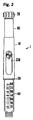
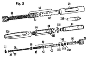
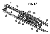
図1および図2は、注射ペンの形の薬物送達デバイス1を示す。このデバイスは、遠位端(図1で下端)および近位端(図1で上端)を有する。薬物送達デバイス1の構成要素部材は、より詳細に図3に示されている。薬物送達デバイス1は、外側ハウジング部材10、内側本体20、ピストンロッド30、駆動体40、ナット50、表示部材60、ボタン70、カートリッジ81を受けるためのカートリッジホルダ80、クラッチ90、クリッカ100、ばね110、キャップ120、および窓挿入物230を含む。ニードルハブおよびニードルカバーを含むニードル配置(図示せず)が、上記で説明されたように交換できる追加構成要素として提供される。ピストンロッド30は支承部31を含む。駆動体は、遠位駆動体部材41、近位駆動体部材42、およびカプラ43を含む。表示部材60は、数字スリーブ61およびダイヤルスリーブ62を含む。クリッカは、遠位クリッカ部材101、近位クリッカ部材102、およびばね103を含む。
1 and 2 show a drug delivery device 1 in the form of an injection pen. The device has a distal end (lower end in FIG. 1) and a proximal end (upper end in FIG. 1). The component members of the drug delivery device 1 are shown in more detail in FIG. The drug delivery device 1 includes an
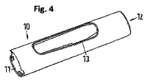
図4に示されている外側ハウジング部材10は、内側本体20を取り付けるための遠位部材11、および近位部材を有する概して管状の要素であり、最大単位(この例では80U)止め具が係合されたときに表示部材60の嵌合面に接触するその内面(図示せず)に、回転硬質止め具12を備える。端面はまた、ボタン70の用量投薬止め具の端部としても機能し、端面の穴は、ダイヤル設定中にも投薬中にも表示部材60を中心に合わせる。開口部13が、窓挿入物230を受けるために設けられる。外側本体10は使用者に、投薬中につかみ反作用するための面を提供する。
The
内側本体20は、異なる半径領域を有する概して管状の要素である。図17〜19で分かるように、内側本体20は、外側本体10に受け入れられると共に、外側本体10に対する内側本体20のいかなる相対運動も防止するように恒久的にそこに固定される。内側本体は、内部スプラインによってクリッカおよび最終用量ナット50を案内して駆動機構を中に収容する機能、ピストンロッド30(親ねじ)を駆動するための内側ねじ山を提供する機能、数字スリーブ61およびダイヤルスリーブ62を外側ねじ山形状によって支持および案内する機能、カートリッジホルダ80を固定する機能、ならびに外側本体10および窓挿入物230を固定する機能を有する。
内側本体20の最も外側の直径部はまた、視覚設計の一部を形成し、キャップ120が、外側本体10からキャップ120を分離するリングとしてのカートリッジホルダ80に固定されているときには可視のままである。この可視リングはまた、カートリッジホルダが適正に嵌められたことを示すために、カートリッジホルダ80上のキャップスナップ機能と位置合わせする凹部を有する。
The outermost diameter of the
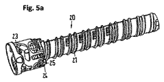
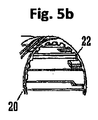
外側ねじ山21が、内側本体20の外面に設けられる。さらに、スプライン22(図5b)が内側本体20の内面に設けられる。これらの内面スプライン22は、ダイヤル設定中でも投薬中でもクリッカ100を軸方向に案内し、また最終用量ナット50が回転しないようにする。スプラインのいくつかは、内部部材の適正な回転組立てを確実にするために幅がより広く、これらの幅がより広いスプラインは、最終用量ナット50が組立て中に遠位駆動スリーブ41上の止め面に突き当たって回転することを助長するために、段を有する入口および傾斜した面を有する。図5bに示された開放端には追加の短いスプラインがあり、これは交互の長いスプライン22と一緒に使用されて、投薬の終わりにボタン70(用量ダイヤルグリップ)を回転ロックすると共に、ボタン70が押し下げられたときの0Uダイヤル止め具の強度を増す働きをする。これは、クラッチ部材90上の雄スプライン機能との係合によって実現される。
An
バヨネット機能23は、カートリッジ取替中にカートリッジホルダ80を機構の中に案内して、カートリッジ付勢ばね110を圧縮し、次に、機構内の軸方向遊びを減らすために、カートリッジホルダ80を短い距離後退させる。内側本体20の内部のスナップ機能は、カートリッジホルダ80を、それが適正に嵌められたときに回転ロックする。これらのスナップの特性は、使用者がカートリッジホルダ80を不完全に嵌めないようにすることを狙いとし、カートリッジ付勢ばね110は、スナップが少なくとも係合し始めていない場合にカートリッジホルダ80を排出する。窓保持ノーズ24は、外側本体10と窓挿入物230のアセンブリが内側本体20に軸方向に挿入されたときに窓挿入物230を保持する。直径方向に向かい合わせの2つの止め面25が、数字スリーブ61の回転端位置を画成する。この端位置は、最小用量(0U)の用量デテント位置の端部になる。
The
ピストンロッド30は、方向が反対の互いに重なり合う2つの外側ねじ山32、33を有する細長い要素である。これらのうちの1つのねじ山32は、内側本体20の内側ねじ山と係合する。円板状の支承部31がピストンロッド30の遠位端に設けられる。支承部31は、図3に示された別個の部材であっても、所定の破断点を介した一体化部材としてピストンロッド30に取り付けられてもよい。
The
ピストンロッド30は、投薬負荷を駆動体40から支承部31まで伝達して、駆動体40のねじ山インターフェースによってピストンロッド30に対して生成されるトルクを、ピストンロッドが内側本体20内のねじ山を通過するときに追加の軸方向負荷に変換することによって、1:1より大きい機械的利益を生み出す。ピストンロッド30は、支承部31を押すことによってリセットされ、これにより次にピストンロッドが回転し内側本体20の中に戻る。これにより遠位駆動スリーブ41が係合解除し、次に回転して、最終用量ナット50を遠位駆動スリーブ41上のその始動位置まで戻してリセットする。
The
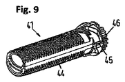
駆動体40は、図に示された実施形態では3つの構成要素を有する概して管状の要素であり、これらの構成要素は、より詳細に図9〜11に描かれている。
The
遠位駆動スリーブ41は、ピストンロッドねじ山33と係合して、用量送達中にピストンロッド30を内側本体20中で駆動する。遠位駆動スリーブ41はまた、カプラ43に恒久的に連結され、そうするとカプラは、リセットクラッチ機能によって近位駆動スリーブ42に解放可能に係合される。駆動スリーブの二等分したものは、ダイヤル設定中および投薬中、回転・軸方向連結されるが、デバイスリセット中は、互いに回転できるように回転デカップリングされる。
The
外側ねじ山44は、最終用量ナット50と係合する。このねじ山形状は、ナット50がその上で移動してダイヤル設定単位の大部分を数える浅い第1の段(図9の左側)と、ストップ面に係合する前に最終用量ナットがその上で速く軸方向に動く急速段と、止め面が係合したときにナット50による軸方向拘束がねじ山形状の適当な長さにわたって及ぶことを確実にする、最後の浅い区間との3つの段を有する。4つの等間隔止め面45が最終用量ナット50上の嵌合止め面51と係合して、ダイヤル設定することができる単位数を制限する。遠位駆動スリーブ41にカチッと留められるカプラ43との間でトルクを伝達するために、スプライン46が遠位駆動スリーブ41の近位端に設けられる。
The
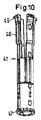
図10に示される近位駆動スリーブ42は、クリッカ部材100およびクラッチ90を支持し、回転運動を用量ボタン70からカプラ43および遠位駆動スリーブ41まで伝達する。
The
近位駆動スリーブ42の遠位端に位置する歯機能47がカプラ43上のリセットクラッチ機能と係合して、ダイヤル設定中および投薬中に駆動スリーブの両半分を連結する。リセット中、これらの歯47が係合解除する。
A tooth feature 47 located at the distal end of the
いくつかのスプラインが、遠位/近位クリッカ部材101、102と係合する近位駆動スリーブ42の外面に設けられて、ダイヤル設定中および投薬中の相対回転を防止する。近位駆動スリーブ42の中間領域に位置する別のスプラインが、クラッチ90部材と係合する。これらのスプラインは、様々なクリッカ部材が誤って上下逆に組み立てられないように非回転対称に配置される。
Several splines are provided on the outer surface of the
近位駆動スリーブ42の近位部分は、4つのアームすなわちフィンガ48を有する。フック状の支承部面49が、可撓フィンガ48の端部のフランジセグメントの下側(図10で見て)に存在する。可撓フィンガ48は、間隙またはスロットで分離され、これらは、ボタン70がクラッチ90にカチッと留まるための空間を作り、またこれらのフィンガがダイヤルスリーブ62と近位駆動スリーブ42の組立て中に内側に曲がることを可能にもする。組立て後にフック49は、ばね103からの反力を受けて近位駆動スリーブ42をダイヤルスリーブ62に対して保持する。投薬中、ボタン70は、クラッチ90およびクリッカ部材を介してばね103を押し下げ、このばね103は、カプラ43を通して近位駆動スリーブ42に対して反作用し、次に、この近位駆動スリーブは、これらの支承面を通して軸方向負荷をダイヤルスリーブ62に加える。この軸方向負荷は、ダイヤルスリーブ62を駆動し、したがって、数字スリーブ61を内側本体20の螺旋ねじ山に沿って駆動して、数字スリーブ61の0U止め面が内側本体20に接触するまでデバイスの本体の中に戻す。
The proximal portion of the
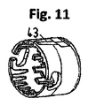
図11に示されるカプラ43は、駆動スリーブの二等分したものを、リセット中はデカップリングできるようにしながら、ダイヤル設定中および投薬中に一緒に連結する。カプラ43はまた、最終用量保護止め負荷を近位駆動スリーブ42から遠位駆動スリーブ41まで伝達しなければならない。歯46および歯47にそれぞれ係合する2つの歯のセットがカプラ43内に設けられる。カプラ43は、遠位駆動スリーブ41の上にカチッと留められて、近位駆動スリーブ42に対して制限された相対軸方向運動を可能にする。
The
ナット50は、内側本体20と駆動体40の遠位駆動スリーブ41との間に設けられる。止め面51は、止め面51が遠位駆動スリーブ41の止め面45に接触した場合にダイヤル設定できる単位数を制限するために、最終用量ナット50の近位面に位置する。最終用量ナット50の機能は、使用者が限定量を超えてダイヤル設定することを防止することである。この制限は、カートリッジ81の投薬可能容積に基づいており、到達したとき、使用者はカートリッジ81を取り替え、デバイスをリセットしなければならない。
The
ナット50の外側リブ52が内側本体20のスプライン22に係合する。ナットの内側ねじ山53が遠位駆動スリーブ41の外側ねじ山44に係合する。代替形態として、スプラインおよびリブをナット50と駆動体40の間の境界面に設け、ねじ山をナット50と内側本体20の間の境界面に設けることもできる。別の代替形態として、ナット50は、たとえば半割ナットとして設計される。
The
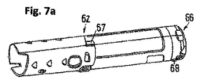
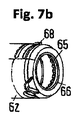
表示部材60は、数字スリーブ61およびダイヤルスリーブ62から構成される概して管状の要素であり、これら2つの構成要素は、これらを軸方向拘束および回転拘束するように組立て中に一緒にしてカチッと留められ、したがって、単一部材として機能する。
The
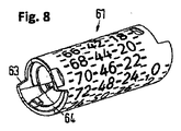
図8に描かれた数字スリーブ61の主要機能は、ダイヤル設定された用量を表示するために用量数を印刷できる面を提供すること、内側本体20にねじ山が付けられた場合に、ピストンロッド30上の螺旋ねじ山形状をたどるように内部機構の螺旋経路をダイヤル設定中に案内すること、ならびにダイヤルスリーブ62に取り付けることである。
The primary function of the
数字スリーブ61は、ダイヤル設定中および投薬中に外側本体10内に完全に密閉されるように設計され、したがって、使用者にはダイヤル設定用量だけが窓開口部を通して見える。数字スリーブは、内側にダイヤル設定されたときにその行程を制限するための0U(最小用量)止め面63を有するが、外側ダイヤル設定条件を制限する80U(最大用量)止め面はダイヤルスリーブ62上に位置する。各投薬ストロークの終わりに、この止め面63は、内側本体20上の嵌合面25と係合して数字スリーブ61の回転位置を制限する。
The
螺旋駆動面64は、ダイヤル設定中および投薬中に内側本体上の螺旋経路21をたどるように数字スリーブ61を案内するねじ山を形成する。
The
ダイヤルスリーブ62は、組立て後に相対運動が不可能になるように数字スリーブ61と組み立てられる。その部材は、成形と組立ての両方を可能にするために、別個の部材として作られる。また、数字スリーブ61は、たとえば黒色の用量数字に対するコントラストを得るために、好ましくは白色であるのに対し、ダイヤルスリーブ62の色は、美的感覚に適合させるように、あるいは薬物タイプを区別するように選択することができる。
The
用量近位端にダイヤルスリーブ62は、ダイヤル設定中にクラッチ部材90と係合し投薬中にクラッチから係合解除する内側クラッチ機能65を有する。これらのクラッチ機能65は、ダイヤル設定中、および0U止め具と80U止め具が係合されるとき、ダイヤルスリーブ62をクラッチ90に回転ロックする。ボタン70が押し下げられるとき、これらのクラッチ機能は係合解除して、クラッチ90および駆動機構が軸方向に動くと同時に、ダイヤルスリーブ62および数字スリーブ61が0U開始位置まで回転して戻ることを可能にする。
The
ダイヤルスリーブ62は、ダイヤル設定中にクラッチ90および数字スリーブ61との係合により外側に回転し、投薬中に、ダイヤルスリーブの端部のフランジ状支承面66に対し近位駆動スリーブ42によって加えられた軸方向力を受けて、内側に逆に回転する。この支承面66は、投薬中に、近位駆動スリーブ42の可撓アーム48と係合する。直径方向に向かい合う2つの面67が、最大用量(たとえば、80U)がダイヤル設定されたときに外側本体10と係合して、最大用量止め面を形成する。
The
ラチェットアーム68が、投薬中に可聴フィードバックを提供するようにボタン70(用量ダイヤルグリップ)上のラチェット機能と係合して、1単位が送達されるごとに1つのクリック音を与える。さらにこれは、使用者が、ボタン70が押し込まれたまま数字スリーブ61をつかみ、部分的に外側にダイヤル設定された位置から外向きに回転させることを防止する。これはピストンロッド30を逆に巻くことになり、これがその後のダイヤル設定用量に対して過少用量をもたらすことになる。これはさらに、0U止め具を強化する。
A
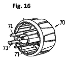
図16に示されるボタン70は、用量ダイヤルグリップとして機能し、クラッチ90によって保持されて使用者の動作をクラッチに伝達する。これはまた、ダイヤルスリーブ62上の、可聴フィードバック(ラチェットクリック音)を与える投薬クリッカとして機能するラチェットアーム68と係合するラチェット歯71と、外側本体10と共に用量完了止め面として機能する端面72とを保持する。すなわち、この端面72は、投薬中にそれが外側本体10と接触するときに端部位置を画成する働きをして、用量精度を改善する非常に確実な止め具を提供する。
The
ボタン70の中心のスリーブ状部分は、フック状のスナップ機能74をそれぞれの遠位端に有する4つのアーム73を備える。アーム73は、クラッチ90と係合してトルクをボタン70からクラッチを経由してダイヤルスリーブ62および近位駆動スリーブ42まで伝達するスプライン付面を形成する。スナップ機能74は、クラッチ90の開口部に係合し、ボタン70をペン本体10の外に引っ張る軸方向負荷が加えられたときに、傾斜したアンダーカット面によって係合を維持するように設計されている。アーム73間の空間は、用量投薬中にボタン70が押し下げられ解放されたときに、近位駆動スリーブ42の可撓アーム48がボタン70およびクラッチ90に対して自由に摺動するための隙間を与えるポケットを画成する。
The central sleeve-like portion of the
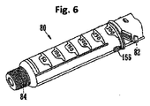
カートリッジホルダ80は、バヨネット連結部82によって内側本体20に取り付け、投薬予定の薬剤を含むガラスアンプルまたはカートリッジ81を収容する。カートリッジホルダ80は、後面(図6で見て)に開口部83を含み、これは、使用者につかまれた場合に、カートリッジホルダが内側本体20から取り出されるときにアンプルが外に落ちることを防止する。前面には用量数目盛が印刷される。ねじ付遠位端84は、使い捨てペン型針を取り付けるために使用される。
The
管状クラッチ90が、表示部材60とボタン70の間に設けられる。クラッチは、ボタン70に対して固定され、このボタンを保持し、また一緒になってこれらが、ボタン70が投薬中に押し下げられたときに近位駆動スリーブ42に対して軸方向に移動して、クラッチ歯をダイヤルスリーブ62から係合解除する。これはまた、トルクをボタンから近位駆動スリーブ42まで伝達し、ダイヤル設定負荷および0U/80U止め負荷をボタンからクラッチ歯を介してダイヤルスリーブおよび数字スリーブまで伝達する。
A
クラッチの内面に設けられた駆動スリーブスプライン91は、近位駆動スリーブ42と係合する。遠位端面にクラッチ付勢歯92が設けられ、これは、近位クリッカ部材102上の類似の歯と嵌合して、ボタン外側位置(ダイヤル設定用量)においてクラッチが、クラッチばね103の付勢作用を受けて近位クリッカ部材102に回転ロックされることを確実にする。歯92は、ダイヤル設定中に近位クリッカ部材102が近位駆動スリーブ42上のスプラインと係合しないように、高さが浅い。4つのスナップ開口部93は、ボタン70のスナップ機能74を保持する働きをする。クラッチは、その近位端近くにスプライン94を有し、これは、投薬の終わりにボタン70が押し下げられた状態で内側本体20にロックして、使用者が0U位置より下でボタン70を回転させることを防止する。
A
クラッチ歯95は、ダイヤルスリーブのクラッチ歯65と係合して、クラッチを介しボタン70を数字スリーブ61に回転連結する。投薬中、クラッチは、これらのクラッチ歯95を係合解除するように軸方向に動き、それによってダイヤルスリーブ62を解放してデバイスの中に回転して戻り、一方でクラッチ90、したがって駆動体40は、軸方向に動いて用量を投薬する。
The
クリッカ100は、遠位クリッカ部材101、近位クリッカ部材102、およびばね103を含む。クラッチばね103は、用量の終わりにボタン70が飛び出て、クラッチ90をダイヤル設定の用意ができているダイヤルスリーブ62と再係合するように、ボタン70に付勢する働きをする。さらにクラッチばねは、クリッカ部材がクリッカとして、また数字スリーブ61のデテント位置として機能するためのばね力を提供する。加えてクラッチばねは、駆動スリーブの二等分したもの41、42を、デバイスリセット中には係合解除できるようにしながら、ダイヤル設定中および投薬中は回転係合のままにしておく。
The
遠位クリッカ部材101は、近位駆動スリーブ42に恒久的にスプライン連結され、また近位クリッカ部材102と係合し、そうして近位クリッカ部材が内側本体20にスプライン連結される。ダイヤル設定中、駆動スリーブが内側本体に対して回転すると、2つのクリッカ部材101、102は、クラッチばね103の圧縮力を受けて互いに回転する。各クリッカの端面に形成されたクリッカ歯と合わさったこの力は、クリック音をもたらし、ダイヤル設定デテント位置もまたもたらす。
The
投薬中、2つのクリッカ101、102は、投薬負荷を受けて一緒になるように押し付けられ、したがって、近位駆動スリーブ42と内側本体20の間の相対回転を防止して、用量を送達するようにピストンロッドを前方に駆動する。内側穴のスプライン104は、遠位クリッカ部材101を常に近位駆動スリーブ42に連結するが、投薬中にボタン70が押し下げられたとき、およびダイヤル設定中に2つのクリッカが互いに乗り越えたときには、自由な軸方向運動を可能にする。遠位クリッカ部材101上と近位クリッカ部材102上の両方のクリッカ歯105、106の輪郭は同一であり、ダイヤル設定中にばね103からの圧縮負荷を受けて互いに乗り越える。
During dosing, the two
近位クリッカ部材102は、ダイヤル設定中も投薬中も内側本体20との相対回転を防止する外側スプライン107によって内側本体に恒久的にスプライン連結されて、ダイヤル設定中にクリック音をもたらし、投薬中に近位駆動スリーブ42の回転をロックする。追加の円筒成形スプライン108もまた、ボタン70が押し下げられたときに近位クリッカ部材102を近位駆動スリーブ42に回転連結し、これは使用者が、ボタンが押し下げられた状態で80単位を超えてダイヤル設定することを防止する。近位クリッカ部材102は、近位クリッカ歯106に加えて、反対側の端面にクラッチ付勢歯109を有する。これらの歯は、クラッチ上の類似の歯92と嵌合して、ボタン外側位置(ダイヤル設定用量)でクラッチが、クラッチばね103の付勢作用を受けて近位クリッカ部材102に回転ロックされることを確実にする。
The
カートリッジ付勢ばね110は、2つの構成要素として1つずつ、下側が1番目で上側が2番目に組み立てられる。このばね組合せは、許容範囲の極値で端部負荷をカートリッジ81に加える働きをして、カートリッジを前方へ、カートリッジホルダ80のフェルールの端面に対し付勢する。これは、使用者が針を取り外し、また取り付けるときに、針カニューレとカートリッジのセプタムの間の摩擦によりカートリッジ81をカートリッジホルダ80に対して軸方向に動かさないことを確実にする。バイアスばね110はまた、使用者が対抗してカートリッジホルダ80を連結しなければならない力をもたらすようにも作用し、この力は、このバヨネットジョイントの触覚フィードバックを増加する。ばね110はまた、カートリッジホルダが安全確実な位置にまで回されていない場合にカートリッジホルダ80を排出する働きをして、この間違いが使用者に目立つようにする。
The cartridge biasing spring 110 is assembled as two components, one at the lower side and the second at the upper side. This spring combination acts to apply an end load to the
キャップ120は、カートリッジホルダ80を損傷から保護し、カートリッジ81自体をセプタムまわりの領域へのほこり汚れ侵入から保護する働きをする。キャップは、標準的なペン型注射器針を収容するように設計されている。
The
窓挿入物230は、用量数字をたとえばその印刷サイズから約25%拡大するレンズを含む。窓挿入物230は、印刷面を摩耗から保護するために、また窓開口部から入る光を最大にして用量数字、およびこれらの数字まわりの白い領域の均一な照明を与えるために、裏面印刷される。ダイヤル設定された用量を示す矢印が、窓開口部に隣接して印刷される。
The
以下では、薬物送達デバイスおよびその構成要素の機能について、図17〜19を参照してより詳細に説明する。 In the following, the function of the drug delivery device and its components will be described in more detail with reference to FIGS.
このデバイスを使用するには、使用者は用量を選択しなければならない。図17に示された開始(静止)状態では、表示部材60は、ダイヤル設定された用量数を使用者に示す。ダイヤル設定された単位数は、外側本体10の用量窓230を通して見ることができる。表示部材60と内側本体20の間のねじ係合により、ボタン70が時計回りに回転すると、表示部材60がデバイスを出て螺旋状に進み、送達予定の単位の数に徐々に達することになる。図18は、ダイヤル設定の中間段階を示す(たとえば80単位の7)。
To use this device, the user must select a dose. In the start (stationary) state shown in FIG. 17, the
用量設定中にボタン70、駆動体40および表示部材60は、クラッチ90を介して一緒に回転ロックされる。さらに、ボタン70、駆動体40および表示部材60は、軸方向に連結される。したがって、これら3つの部材は、用量設定中に外側ハウジング10を出て螺旋状に進む。ボタン70が時計回りに回転することにより駆動体40が回転することになり、そうしている間、駆動体はダイヤル設定の間ずっと固定されたままのピストンロッド30に沿って進む。クリッカ配置100は、用量をダイヤル設定するときに触知でき可聴であるフィードバックを使用者に提供する。80単位の最大設定可能用量において、止め機能12と67は係合して、これ以上のダイヤル設定を防止する。
During the dose setting, the
最終用量ナット50は、投薬単位の数を数える機能を提供する。ナット50は、カートリッジ寿命の終わりにデバイスをロックし、そのため使用者がそれ以上の薬物をダイヤル設定することはできない。最終用量ナット50と駆動体40は、上記で説明したねじ付境界面を介して連結することができる。さらに、最終用量ナット50は、ナット50と内側本体20が一緒になって(常時)回転ロックされるように、スプライン22に組み込まれる。ダイヤル設定中に駆動体40が回転すると、ナット50は、ねじ山44に沿って前進することになる。ナット50は、内側本体20の中で軸方向に常に自由に摺動し、そのためナットの前進が可能になる。図9に示されたねじ山44のピッチが最終用量に向かって変わることにより、カートリッジ寿命の終わりのロックアウト状態に向かうナット50の前進が軸方向に加速する。寿命の終わりの状態で、最終用量ナット50の止め機能51は、駆動体40上の対応する機能45と接触する。内側本体20とのスプライン接触は、これらの止め機能45によって伝達されるいかなるトルクにも対応する。
The
所望の用量がダイヤル設定されていると、デバイス1は薬物投薬の準備ができている。薬物投薬は基本的に、ボタン70を押すことが必要であり、これによりクラッチ90がダイヤルスリーブ62から係合解除することになり、それによって、表示部材60とボタン70の間の相対回転が可能になる。すべての状態において、駆動体40とボタン70は一緒に、アーム73とフィンガ48の係合によって、また近位駆動スリーブ42上の対応するスプラインに係合するスプライン91によって、回転ロックされている。すなわち、クラッチ90が係合解除された(ボタン70が押し込まれた)状態で、ボタン70と駆動体40は一緒に回転ロックされ、ボタン70、駆動体40および表示部材60はなお軸方向に連結されている。
When the desired dose is dialed, the device 1 is ready for drug dosing. Drug dosing basically requires the
用量を投薬するとき、用量ボタン70およびクラッチ90は、クラッチばね103を圧縮する機構に対して軸方向に動く。近位クリッカ部材102が内側本体20にスプライン連結され、クリッカ歯105、106を貫通する軸方向負荷が遠位クリッカ部材101を近位クリッカ部材102に回転ロックするので、この機構は、軸方向に動くことを強制されるが、ダイヤルスリーブ62および数字スリーブ61は自由に回転して外側ハウジング10の中に戻る。ピストンロッド30、駆動体40および内側本体20の間の嵌合ねじ山の相互作用は、2:1の機械的利益を出す。言い換えると、駆動体40を軸方向に前進させることがピストンロッド30を回転させ、この回転が、内側本体20とピストンロッド30のねじ係合により、ピストンロッドを前進させる。用量投薬中、投薬クリッカ68、71が動作しており、これにはボタン70および表示部材60を要する。投薬クリッカは主に、薬物が投薬されているという可聴フィードバックを使用者に提供する。
When dispensing a dose, the
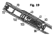
このステップの終了は図19に示されている。この時点で用量は完了しており、使用者が用量ボタン70の端部から力を取り除くと、クラッチばね103はこの用量ボタン70を後方へ押して、クラッチとダイヤルスリーブの間で歯65と95を再係合する。
The end of this step is shown in FIG. At this point, the dose is complete, and when the user removes the force from the end of the
デバイスをリセットすることは、カートリッジホルダ80を除去すること、および空カートリッジを満カートリッジ81と交換することから始まる。カートリッジホルダが再取付けされると、新しいカートリッジの栓が支承部31に接触し、それによって、ピストンロッド30がハウジングの中に押し戻される。最初にピストンロッド30は、内側本体20の中にねじのように回って入り、それによってカプラ43を近位駆動スリーブ42から、ばね103の付勢力に抗して係合解除する。係合解除されるとカプラ43は、遠位駆動スリーブ41と一緒に自由に回転し始め、そうすることを、カートリッジホルダ80が軸方向に内側本体20と係合するまで動きながら続ける。すなわち、遠位駆動スリーブ41は、クリッカ部材101と102が一緒になるようにばね103によって圧縮されているので依然として内側本体20内に回転拘束されている、近位駆動スリーブ42に対して回転する。遠位駆動スリーブ41が回転すると、最終用量ナット50がその(遠位)開始位置にリセットされる。カートリッジホルダ80を内側本体20に連結することが、カプラ43と、したがって遠位駆動スリーブ41と近位駆動スリーブ42の再係合を可能にするバヨネット構造23により、機構を後退させる。
Resetting the device begins with removing the
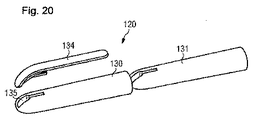
以下では、図20〜30を参照してキャップ120についてより詳細に説明する。図20〜25は、キャップ120の取付け手段を示す。
Hereinafter, the
遠位端121および近位端122を有するキャップ120は、カートリッジホルダ80を覆って損傷から保護する働き、およびカートリッジ81自体を、セプタムまわりの領域へのほこりおよび汚れの侵入から保護する働きをする。キャップ120は、キャップ120の近位開口部からキャップ120の中へと動くペン型注射器の遠位区間を収容するように設計されている。キャップ120は、カートリッジおよびカートリッジホルダ80に取り付けられた針配置180がキャップ120の内側に位置するようにして、薬物送達デバイス1に取り付けられる。キャップ120は、薬物送達デバイス1の使用の前に取り外される。キャップ120の内側は、カートリッジおよびカートリッジホルダ80に取り付けられる針配置180のために十分な空間があるように形成される。カートリッジホルダ80および針配置180を案内および保持する手段(図20〜25では図示せず)が、キャップ120の内面に設けられる。
A
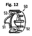
図20は、外側キャップ要素130、内側キャップ要素131、およびクリップ要素134を含むキャップ120の分解組立図を示す。一緒に組み立てられて取外し可能キャップ120を形成することができる外側および内側キャップ要素130、131は、それぞれ金属スリーブおよびプラスチックスリーブで作られている。外側と内側キャップ要素130、131は、適切な手段、たとえば接着手段、ポジティブロッキングおよび/または摩擦ロッキングによって連結される。クリップ要素134は、キャップ120の手段によって注射器ペン1をシャツまたはジャケットのポケットに連結できるようにし、その理由のために常に便利である。外側キャップ要素130の開口部135は、クリップ要素134が内側キャップ要素131にカチッと留まることができるようにする。
FIG. 20 shows an exploded view of the
外側キャップ要素130は、好ましくは金属で作られ;内側キャップ要素131は、好ましくはプラスチックで作られる。金属外側キャップ要素130とプラスチック内側キャップ要素131の組合せにより、高品位の外見および快い手触りを提供することが可能になる。キャップ120は重すぎず、快適な取扱いを可能にする。キャップ120の内側構成要素の設計により、クリップ要素134を保持することが可能になり、キャップ120の内側のカートリッジホルダ80に嵌められる標準的な針および針カバーを収容するのに十分な空間がもたらされる。
外側キャップ要素130は、ポリマー製内側キャップ要素131を覆う金属皮膜を提供する0.4mm〜0.6mm厚のアルミニウム要素である。キャップ120の形状は、完全にプラスチックで作られたキャップの1つと類似している。このようなキャップ120は、完全にプラスチックで作られたキャップに、取付け中の触感が変わることなく取って代わることができる。同様なプラスチック機能は、そうでなければ無地の金属スリーブを既存のプラスチックカートリッジホルダ保持機能に取り付ける場合に生じる摩耗の危険を低減する。
The
内側および外側キャップ要素131、130は、スリーブ形になっている。金属スリーブは、金属シートから搾り加工され、次に、少なくとも外面を覆って陽極酸化される。陽極酸化は、高品位で長持ちする外面をキャップ120に提供し、キャップ120に様々な金属色を与えることを可能にする。金属外側キャップ要素130およびプラスチック内側キャップ要素131を含む取外し可能キャップ120は次に、やはり同様の金属スリーブでできているペン型ハウジング/機構に取り付けられて、高品位の美しく堅牢な表面を有する再使用可能注射デバイスを提供する。
The inner and
この設計は、コストを最小限にし、堅牢で長持ちする機能を提供する。したがって、金属とプラスチックのスリーブ形構成要素の組合せを使用することにより、プラスチックスリーブを、プラスチックカートリッジホルダキャップ保持手段に取り付ける機能と共に成形することが可能になる。 This design minimizes costs and provides a robust and long lasting feature. Thus, by using a combination of metal and plastic sleeve-shaped components, it is possible to mold the plastic sleeve with the function of attaching to the plastic cartridge holder cap retaining means.
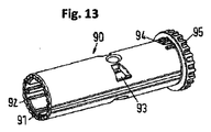
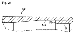
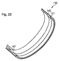
図21は、外側キャップ要素130の近位領域の断面図を示す。図22は、この構成要素の三次元切取図を示す。外側キャップ要素130は、開放端部で厚さが低減されている、深絞り加工された金属スリーブによって形成される。非常に近位の領域が丸められて、丸みのある、または折曲げ端161を形成する。このような材料の巻き返しでビーディングを形成する。この実施形態では、外側キャップ要素130の材料は1回曲げられている。しかしながら、材料は1回より多く曲げることもできる。このような曲げにより、外側キャップ要素130の内面に鋭い縁部147を形成することが可能になる。
FIG. 21 shows a cross-sectional view of the proximal region of the
深絞り処理によって生じる開放端の薄い材料、およびその後にビーディングを形成することにより、周辺凹部143が外側キャップ要素130の内面に形成される。この凹部143は、キャップ120をカートリッジホルダ80に取り付けるときに内側キャップ要素131がその形に変形することができる空間として機能する。鋭い縁部147は、凹部143の近位縁部であり、組立て後にプラスチック内側キャップ要素131を保持する働きをする。
A
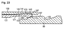
図23は、薬物送達デバイス1に取付け中のキャップ130の近位区間141の断面図を示す。取付け中、内側および外側キャップ要素131、130を含むキャップ120は、カートリッジホルダ80がキャップ120の中へ入るようにしてカートリッジホルダ80に対して近位に動く。
FIG. 23 shows a cross-sectional view of the proximal section 141 of the
外側キャップ要素130は、外側キャップ要素130の内面に空洞143を含む近位区間141を有する。空洞143は、この実施形態では円周方向に伸びる凹部として形成されている。あるいは、空洞143は、内側キャップ要素131の変形可能領域151の形状およびサイズに対応する別の形を有することもできる。
The
空洞143の領域内の外側キャップ要素130の厚さは、外側キャップ要素130の遠位区間または中間部の厚さよりも薄い。空洞143の遠位縁部145は、外側キャップ要素130の中間部と近位区間141に位置する空洞143との間のゆるやかな移行を可能にする傾斜路形に形成される。空洞143の近位縁部147は、遠位縁部145よりも急峻であり、鋭い縁部として形成される。
The thickness of the
内側キャップ要素131は、内側キャップ要素131の近位区間の内側に位置する、また薬物送達デバイス1のカートリッジホルダ80上に位置するキャップ保持手段155と係合するのに適している、キャップスナップ手段149を含む。キャップスナップ手段149は、キャップスナップ手段149を薬物送達デバイス1のキャップ保持手段155にロックするために、またキャップスナップ手段149をキャップ保持手段155から解放するために、取付けおよび取外し中に変形することができる変形可能領域151の少なくとも近位区間によって形成される。キャップスナップ機能149は、高くなったノーズ153またはフィンガ、および空洞171を含み、空洞171の領域内の内側キャップ要素131は他の領域よりも薄く;空洞171は変形可能領域151によって形成される。ノーズ153は、遠位斜面より急峻ではない近位斜面を有する。
内側キャップ要素の空洞171の厚さの低減によりキャップスナップ手段149の変形が可能になり、それによってキャップ保持機能155に係合することが可能になる。外側キャップ要素130の空洞143により、外側および内側キャップ要素130、131の間に隙間がある。変形可能領域151は、外側キャップ要素130の空洞143の中に変形可能である。言い換えると、変形可能領域151は、外側および内側キャップ要素130、131の間の隙間の中に変形可能である。
Reducing the thickness of the inner
キャップスナップ手段149の近位端173は、空洞143の近位縁部147を近位で越えて延び;近位縁部147は、キャップスナップ手段149の近位端173の外向きの動きを防止して、この端部を円形に保持する。
The
キャップ保持手段155は、プラスチックカートリッジホルダ80の外面に位置する。キャップ保持手段155は、台形、円形、三角形または他の任意の形状として形成されるベース領域がある高所157を含む。一実施形態では、図3および図6に示されるように、2つの高所157がカートリッジホルダ80の両側に配置される。一実施形態では、薬物送達デバイス1上に均等または不均等に間隔をあけて配置されている2つ以上の高所がある。
The cap holding means 155 is located on the outer surface of the
高所157は、近位斜面および遠位斜面を有し;後者は高所157の近位斜面よりも急峻ではない。遠位斜面は、取付け中にノーズ153の近位斜面が高所157の上部を越えて容易に摺動できるようにする。高所157とノーズ153の両方のより急峻な斜面は、ノーズ153が高所157の上部を越えて動いた後、それが遠位に動くことを妨げ、それによって、取付け後のノーズ153の後向きの動きが防止される。しかし、キャップ120を引っ張る使用者による十分な力の衝撃は、ノーズ153を再び高所157を越えて遠位に引っ張り、それによってキャップ120を取り外すことが可能になる。ノーズ153の遠位斜面および高所157の近位斜面が急峻であるので、取外しに必要な力は取付けに必要な力よりも大きく、そのためキャップ120が偶発的に取り外されることが防止される。しかしながら、代替のノーズ153および高所157の実施形態では、対称である他の斜面設計があり得る。
The
ノーズ153が高所157を越えて摺動するとき、ノーズ153は外側キャップ要素130の方へ押される。キャップスナップ手段149の近位端173がその位置に、外側キャップ要素130の近位縁部147によって保持されているので、結果として生じるトルクが変形可能領域151を外向きに変形させ、ノーズ先端が高所157を越えて摺動することを可能にする。外側キャップ要素130の空洞143は、キャップ120の取付け中にノーズ153が高所157を越えて摺動するとき、プラスチック内側キャップ要素131の変形の少なくとも一部に対応するための空間を与える。
As the
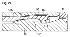
図24は、薬物送達デバイス1への取付け後のキャップ120の近位区間の断面図を示す。
FIG. 24 shows a cross-sectional view of the proximal section of the
ノーズ153は、高所157の近位縁部の後ろに係合される。高所157は、内側キャップ要素131の空洞171に係合する。ノーズ153は高所157を越えて摺動しているが、キャップスナップ機能149は依然として、外側キャップ要素130の空洞143の中に変形されている。キャップスナップ手段149の近位端173を強制的にその位置にする外側キャップ要素130の近位縁147と、変形可能領域151を外側キャップ要素130の空洞143に押し込む高所157との組合せにより、キャップスナップ機能149が高所157を越えて適正に整合することになり、それによってキャップ120が取付け位置に保持される。
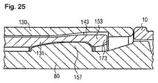
図25は、薬物送達デバイス1への取付け後のキャップ120の別の実施形態の近位区間の断面図を示す。
FIG. 25 shows a cross-sectional view of the proximal section of another embodiment of the
この実施形態は、上述のものとは内側キャップ要素131の設計が異なる。キャップスナップ手段149の近位端173は、空洞143の近位縁部を越えて延びず、これにより、取付け中に近位縁部173もまた空洞143に入るようにした変形が可能になる。この実施形態では、高所157はキャップスナップ手段149を変形するにすぎず、トルクが大幅に低減されるので、キャップスナップ手段149に衝撃を与える応力が小さい。
This embodiment differs in the design of the
以下の図26〜30は、固定要素として機能するクリップ要素134の取付けを示す。
Figures 26-30 below show the attachment of a
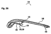
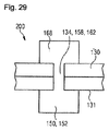
図26は、固定要素134またはペン型デバイスなどの薬物送達デバイス1用のクリップ要素を示す。クリップ要素134によって、薬物送達デバイスのキャップもしくはキャップアセンブリ(下記参照)、または薬物送達デバイスの固定もしくは取付けは、別の構成要素に、たとえばデバイスの使用者のシャツポケットに固定することができる。それに応じて、固定要素134は、細長い形状と、固定要素134の遠位端(図26では左側)のわずかな湾曲とを有する固定部分168すなわち本体を含む。固定要素134はさらに、案内要素150を含む。案内要素150は、固定要素134の遠位端近くの、上記の湾曲部の内側に配置される。案内要素150は、固定要素134が、案内要素150を受ける要素によって、好ましくは固定要素またはデバイスの長手方向軸に沿って案内されるようにレールを構成する、または含む。案内要素は、固定要素134の軸方向延長部の半分未満を越えて延びる。案内要素150はさらに、上記の案内機能を助長するためのT字形横断面を含む(たとえば、図29も参照)。T字形断面を形成するために、案内要素150は受け部分152を含む。受け部分152は、T字形断面の「T」の水平の一画すなわち横棒を構成する。好ましくは、受け部分152は、たとえばキャップアセンブリの中で固定要素134が取り付けられるべき構成要素の、1つまたはそれ以上の開口部もしくは開口部で受けられるように構成される(図29および図30参照)。
FIG. 26 shows a clip element for a drug delivery device 1 such as a
さらに、案内要素150は、案内部分158を含む。案内部分158は、好ましくは、案内要素150のT字形断面の「T」の水平の一画すなわち横棒を構成する。案内部分158は、固定要素134の固定部分168を受け部分152に連結するウェブである。案内部分158はさらに、たとえば上記のキャップアセンブリの中で固定要素134が取り付けられるべき構成要素の、1つまたはそれ以上の開口部で受けられる、またはその中に配置される。
In addition, the
案内要素150は、固定要素134の内側で半径方向に突出する突起を含む、または構成する連結機能154を含む。好ましくは、連結機能154は、たとえば内側キャップ要素131(図30参照)の対応連結機能と相互作用するように構成される。連結機能154は、案内要素150の近位端に配置される。連結機能154はさらに、案内要素150の遠位面を含む、または構成する。
The
案内要素150または固定要素134はさらに、当接機能156を含む。当接機能156は、固定要素134の長手方向軸に垂直な半径方向当接面と、製造および組立ての際の許容誤差により生じる固定要素134と外側キャップ要素130の間の隙間があれば隠す、または覆い隠すように設計されている長手方向当接面とを含む。当接機能156は、好ましくは、たとえばキャップアセンブリ200(図30参照)の中で固定要素134が取り付けられるべき、1つまたはそれ以上の対応する構成要素に当接するように構成される。
The guiding
さらに、固定要素134は、取付け機能160を含む。取付け機能160は、別の構成要素と相互作用するように構成される。取付け機能160は隆起を含む、または構成する。取付け機能はさらに、案内要素150から軸方向に間隔があけられ、固定要素134の近位端近くに配置される。取付け機能160は、好ましくは、機械的接触によって外側キャップ要素130と相互作用するように構成される。それによって、キャップアセンブリまたは薬物デバイスを、アセンブリまたはデバイスの使用者のシャツポケットなどの別の要素に固定または取付けることが簡単になり、または助けられる。特に、前記機械的接触は摩擦を増大させ、またそれによって、キャップアセンブリおよび別の要素の取付けの確実性を向上させる。
Further, the
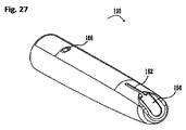
図27は、外側キャップ要素130の斜視図を示す。外側キャップ要素130は細長い形状を含む。外側キャップ要素130はさらに、スリーブ状の形状を含む。好ましくは、外側キャップ要素130は金属で作られ、たとえばアルミニウムから作られる。この目的で外側キャップ要素130は、好ましくは深絞りで形成または製造される。外側キャップ要素130はさらに、開口部164を含む。開口部164は、外側キャップ要素130の遠位端に配置される。開口部164は、好ましくは打抜きによって外側キャップ要素130から形成される。外側キャップ要素はさらに、図27には明確に示されていない近位開口部を含む。開口部164内に、図26に描かれている案内要素150に対応する、対応案内機能162が形成される。対応案内機能162は、開口部164から始まって、外側キャップ要素130の近位方向に延びる。対応案内機能162は案内スロットである。対応案内機能162は、案内要素150の案内部分158を受けるために、案内部分が対応案内機能162の内側に配置されるように構成される。好ましくは、開口部164、対応案内機能162および固定要素134は、案内要素150を開口部164に導入できるように、または開口部164で受けることができるように構成される。次に、固定要素が近位に押されると、案内部分158は、対応する案内機能162で受けられ、またはその中に配置され、受け部分152は、好ましくは開口部164の残りだけで受けられ、外側キャップ要素130および/または内側キャップ要素の内側に配置される(図29および図30参照)。
FIG. 27 shows a perspective view of the
外側キャップ要素130はさらに、凹部166を含む。凹部166は、好ましくは、たとえば固定要素134と外側キャップ要素130がキャップアセンブリ200に組み立てられるときに、上記の固定要素の取付け機能160を受ける、またはそれと相互作用する(下記の図29および図30参照)。好ましくは、取付け機能は凹部166の中へと延び、かつ/または凹部166内で外側キャップ要素130と接触する。凹部166は軸方向に、特に近位に、外側キャップ要素130の長手方向軸に沿って開口部164から離隔される。凹部166は、好ましくは、取付け機能に従って、すなわち、取付け機能160(図26参照)の上記の隆起と同じ曲率で形づくられる。
The
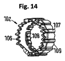
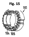
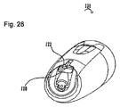
図28は、内側キャップ要素131の斜視上面図を示す。内側キャップ要素131はスリーブであり、外側キャップ要素130に導入されるように構成される。内側キャップ要素131は、対応連結機能170を含む。対応連結機能170は、連結機能154と対応連結機能170の相互作用によって固定要素134を内側キャップ要素131に連結できるように、固定要素134の連結機能154に対応する(図29および図30参照)。対応連結機能170は、内側キャップ要素131の近位面を構成する、または含む。内側キャップ要素131はさらに、開口部172を含む。開口部172は、内側キャップ要素131の遠位端またはその近くに配置される。開口部172はさらに、外側キャップ要素の開口部164と同様に形づくられる(図27参照)。
FIG. 28 shows a perspective top view of the
図29は、キャップアセンブリ200の部材の断面図を示す(図30参照)。アセンブリ200は、固定要素134、外側キャップ要素130および内側キャップ要素131を含む。図23は、上記の構成要素を組み立てられた状態で示す。図29に示された区間の下部にキャップアセンブリ200の内側が示され、上部に外側部材が示されている。描かれた状況では、内側キャップ要素131が外側キャップ要素130内に配置され、固定部材134および/または案内要素150の少なくとも一区間が、外側キャップ要素の開口部164を通って、好ましくはまた、内側キャップ要素の開口部172も通って延びる。この目的で、開口部164と172は、キャップアセンブリ200内で重なり合う。図29にはさらに、上述のように、案内要素150がT字形断面を含むことが示されている(前記Tは上下逆に描かれている)。それによって、固定要素134全体の断面はH状に形づくられる。案内部分158は、対応案内機能162内に配置される(図27も参照)。案内要素150、特に受け部分152は、たとえば、外側キャップ要素130および/または内側キャップ要素131に対する固定要素134の(外向き)半径方向の動きを防止する。これは、対応案内機能162が、受け部分152に対応案内機能162を半径方向に通過することを可能にするには狭すぎるからである。
FIG. 29 shows a cross-sectional view of the members of the cap assembly 200 (see FIG. 30). The
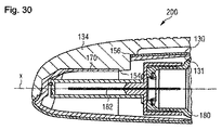
図30は、キャップアセンブリ200の部材の長手方向断面図を示す。キャップアセンブリは、長手方向軸Xを含む。また、キャップアセンブリ200が適用される薬物送達デバイスも図30に示されている。
FIG. 30 shows a longitudinal cross-sectional view of the members of the
固定要素134は、内側キャップ要素131の開口部172および外側キャップ要素130の開口部164を、キャップアセンブリ200が丸みのある形状になるように閉ざす。固定要素134の連結機能154は、少なくとも一部は外側キャップ要素130の開口部164内、ならびに内側キャップ要素131の開口部172内に配置される(図30には開口部が明確に示されていない)。特に、対応案内機能162は、案内要素150の受け部分152を受けるように構成され、その結果、受け部分152が外側キャップ要素130の内側に、また内側キャップ要素131の内側にも配置されるようになる(図29も参照)。
The securing
固定要素134と内側キャップ要素131は互いに連結される。特に、連結機能154は、固定要素134と内側キャップ要素131が互いに連結されるように、スナップ相互作用によって対応連結機能170と相互作用し、好ましくは当接する。固定要素134と内側キャップ要素131は、好ましくは、連結機能154の遠位面と対応連結機能170の近位面とが当接するとき、互いに確実に連結される。上記の構成要素を連結するために、または連結中に、固定要素134および内側キャップ要素131のうちの少なくとも1つが、少なくともわずかに変形される。連結機能154は、内側キャップ要素131が外側キャップ要素130の中に保持されるように、外側キャップ要素130に対する内側キャップ要素131の近位の動き(すなわち、図30で左向き)を阻止する。
The fixing
当接機能156はさらに、内側キャップ要素131の遠位面と、ならびに外側キャップ要素130の遠位面および半径方向面と軸方向に当接する(各面は明確に示されていない)。上述の当接によって、内側キャップ要素131に対する外側キャップ要素130の特に遠位方向の動きが阻止されること、また外側キャップ要素130が固定要素134によって固定されることがさらに容易になる。さらに、当接機能156の上記の当接相互作用が、キャップアセンブリ200に対する機械的安定性をもたらした。
The
図30にはこのことが明確に示されていないが、固定要素134の取付け機能160は、好ましくは外側キャップ要素130の凹部166に機械的に接触する(上記説明参照)。
Although this is not clearly shown in FIG. 30, the
また、たとえばキャップアセンブリ200が適用される薬物送達デバイスの別の構成要素も示されている。このような構成要素は、薬物(明確に示されていない)を保持するカートリッジまたはカートリッジホルダ180に関連する。さらに、カートリッジまたはカートリッジホルダ180からの薬物と流体連通している注射針182が示されている。内側キャップ要素131は針182と、さらにカートリッジまたはカートリッジホルダ180の少なくとも一区間とを収容することが示されている。
Also shown are other components of the drug delivery device to which the
内側キャップ要素は、有利には、射出成形金型一式で1つだけの中子および1つの型空間挿入物を用いた射出成形プロセスによって成形可能になるように設計される。それによって内部部材は、低コスト成形プロセスによって製造することができる。 The inner cap element is advantageously designed to be moldable by an injection molding process using only one core and one mold space insert in a set of injection molds. Thereby, the inner member can be manufactured by a low cost molding process.
キャップ120(図3参照)は、キャップアセンブリ200であるか、またはこれに関連する。カートリッジまたはカートリッジホルダ180は、カートリッジ81および/またはカートリッジホルダ80であるか、またはこれらに関連する。クリップ要素は、固定要素134であるか、またはこれに関連する。
Cap 120 (see FIG. 3) is or is associated with
保護の範囲は、本明細書で上記に示された例に限定されない。本発明は、それぞれの新規の特徴、および特徴の組合せとして具現化され、特に、特許請求の範囲に記載されている任意の特徴のすべての組合せを、この特徴またはこの特徴の組合せが特許請求の範囲または例にたとえ明解に記載されていなくても含む。上記の実施形態の特徴は組み合わされる。構成要素の配置、機能および数は、別の実施形態では変えられる。 The scope of protection is not limited to the examples given hereinabove. The invention is embodied as each novel feature and combination of features, particularly any combination of any feature recited in the claims may be claimed as this feature or combination of features. Include in the scope or examples even if not explicitly stated. The features of the above embodiments are combined. The arrangement, function and number of components can be varied in other embodiments.
1 薬物送達デバイス
10 外側ハウジング部材
11 遠位部材
12 止め具
13 開口部
20 内側本体
21 外側ねじ山
22 スプライン
23 バヨネット機能
24 保持手段
25 止め具
30 ピストンロッド
31 支承部
32 ねじ山
33 ねじ山
40 駆動体
41 遠位部分
42 近位部分
43 カプラ
44 ねじ山
45 止め面
46 スプライン
47 歯機能
48 フィンガ
49 支承部面
50 用量ナット
51 止め面
52 外側リブ
53 内側ねじ山
60 表示部材
61 数字スリーブ
62 ダイヤルスリーブ
63 止め面
64 ねじ山
65 歯
66 接触機能
67 向かい合う面
68 クリッカ
70 ボタン
71 クリッカ
72 端面
73 フィンガ
74 スナップ機能
80 カートリッジホルダ
81 カートリッジ
82 バヨネット連結部
83 開口部
84 遠位端
90 クラッチ
91 駆動スリーブスプライン
92 クラッチ付勢歯
93 スナップ機能
94 スプライン
95 クラッチ歯
100 クリッカ
101 遠位クリッカ部材
102 近位クリッカ部材
103 ばね
104 スプライン
105, 106 クリッカ歯
107 外側スプライン
108 成形スプライン
109 クラッチ付勢歯
110 ばね
120 キャップ
121 遠位端
122 近位端
230 窓
130 外側キャップ要素
131 内側キャップ要素
134 クリップ要素
135 キャップの開口部
136 外側ハウジング部材の開口部
137 (キャップの)端面
141 近位区間
143 空洞
147 縁部
149 キャップスナップ手段
151 変形可能領域
153 ノーズ
155 キャップ保持機能
157 高所
161 折曲げ端
171 空洞
173 近位端
150 案内要素
152 受け部分
154 連結機能
156 当接機能
158 案内部分
160 取付け機能
162 対応案内機能
164 開口部(外側キャップ要素)
168 固定部分
166 凹部
170 対応連結機能
172 開口部(内側キャップ要素)
180 カートリッジ/カートリッジホルダ
182 注射針
200 キャップアセンブリ
X 長手方向軸
DESCRIPTION OF SYMBOLS 1 Drug delivery device 10 Outer housing member 11 Distal member 12 Stopper 13 Opening part 20 Inner body 21 Outer thread 22 Spline 23 Bayonet function 24 Holding means 25 Stopper 30 Piston rod 31 Bearing part 32 Thread 33 Thread 40 Drive Body 41 Distal portion 42 Proximal portion 43 Coupler 44 Thread 45 Stop surface 46 Spline 47 Tooth function 48 Finger 49 Bearing surface 50 Dose nut 51 Stop surface 52 Outer rib 53 Inner thread 60 Display member 61 Number sleeve 62 Dial sleeve 63 Stopping surface 64 Thread 65 Tooth 66 Contact function 67 Opposing surface 68 Clicker 70 Button 71 Clicker 72 End surface 73 Finger 74 Snap function 80 Cartridge holder 81 Cartridge 82 Bayonet connecting portion 83 Opening portion 8 4 distal end 90 clutch 91 drive sleeve spline 92 clutch biasing tooth 93 snap function 94 spline 95 clutch tooth 100 clicker 101 distal clicker member 102 proximal clicker member 103 spring 104 spline 105, 106 clicker tooth 107 outer spline 108 molding spline 109 Clutch energizing teeth 110 Spring 120 Cap 121 Distal end 122 Proximal end 230 Window 130 Outer cap element 131 Inner cap element 134 Clip element 135 Cap opening 136 Outer housing member opening 137 End of cap 141 Position section 143 Cavity 147 Edge portion 149 Cap snap means 151 Deformable region 153 Nose 155 Cap holding function 157 Height 161 Bending end 171 Empty 173 proximal 150 guide element 152 receiving portion 154 connecting function 156 contact function 158 guiding portion 160 attached function 162 corresponding guide feature 164 opening (the outer cap element)
168
180 Cartridge /
Claims (14)
近位端に開口部を有し、さらに、
外側キャップ要素(130)と、
該外側キャップ要素(130)の内部に位置する内側キャップ要素(131)と
を含み、該内側キャップ要素(131)は、変形可能領域(151)およびキャップスナップ手段(149)を含み;
ここで、内側キャップ要素(131)の変形可能領域(151)は、内側キャップ要素(131)と外側キャップ要素(130)の間の隙間(143)の中に変形可能であり、
ここで、外側キャップ要素(130)は金属で作られる、前記キャップ。 A cap (120) for a drug delivery device (1) having a distal end (121) and a proximal end (122);
Having an opening at the proximal end, and
An outer cap element (130);
An inner cap element (131) located within the outer cap element (130), the inner cap element (131) including a deformable region (151) and cap snap means (149);
Here, deformable region of the inner cap element (131) (151), Ri deformable der within the interstices (143) between the outer cap element inner cap element (131) (130),
Here, the outer cap element (130) is Ru made of metal, the cap.
Applications Claiming Priority (3)
| Application Number | Priority Date | Filing Date | Title |
|---|---|---|---|
| EP13182224 | 2013-08-29 | ||
| EP13182224.9 | 2013-08-29 | ||
| PCT/EP2014/068021 WO2015028439A1 (en) | 2013-08-29 | 2014-08-26 | Cap for a drug delivery device |
Publications (2)
| Publication Number | Publication Date |
|---|---|
| JP2016531682A JP2016531682A (en) | 2016-10-13 |
| JP6434026B2 true JP6434026B2 (en) | 2018-12-05 |
Family
ID=49054429
Family Applications (1)
| Application Number | Title | Priority Date | Filing Date |
|---|---|---|---|
| JP2016537252A Active JP6434026B2 (en) | 2013-08-29 | 2014-08-26 | Cap for drug delivery device |
Country Status (9)
| Country | Link |
|---|---|
| US (1) | US11052200B2 (en) |
| EP (1) | EP3038678B1 (en) |
| JP (1) | JP6434026B2 (en) |
| CN (1) | CN105492050B (en) |
| DK (1) | DK3038678T3 (en) |
| ES (1) | ES2774303T3 (en) |
| HU (1) | HUE047773T2 (en) |
| PL (1) | PL3038678T3 (en) |
| WO (1) | WO2015028439A1 (en) |
Families Citing this family (28)
| Publication number | Priority date | Publication date | Assignee | Title |
|---|---|---|---|---|
| HUE047773T2 (en) | 2013-08-29 | 2020-05-28 | Sanofi Aventis Deutschland | Cap for a drug delivery device |
| USD819198S1 (en) | 2016-04-28 | 2018-05-29 | Amgen Inc. | Autoinjector with removable cap |
| TWI729141B (en) | 2016-05-31 | 2021-06-01 | 德商賽諾菲阿凡提斯德意志有限公司 | Cap assembly for a drug delivery device and method for assembling a cap assembly |
| IL269115B2 (en) * | 2017-03-07 | 2023-11-01 | Sanofi Aventis Deutschland | Cap assembly for a drug delivery device, kit for assembling a cap, method for assembling a cap and drug delivery device comprising a cap assembly |
| CN111093739B (en) * | 2017-09-14 | 2022-04-26 | 贝克顿迪金森法国公司 | Safety components and medical devices with safety components |
| CN111356493B (en) * | 2017-11-02 | 2022-12-16 | 赛诺菲 | Buttons and button assemblies for drug delivery devices |
| JP1631211S (en) * | 2017-11-06 | 2019-05-13 | ||
| US12263256B2 (en) | 2019-02-12 | 2025-04-01 | Becton, Dickinson And Company | Medical device to disinfect a skin surface |
| CA3129657A1 (en) * | 2019-02-12 | 2020-08-20 | Becton, Dickinson And Company | Cap for disinfection of a medical device |
| CN113474025B (en) | 2019-02-26 | 2023-12-01 | 贝克顿迪金森法国公司 | Autoinjector with audio indicator |
| KR102615193B1 (en) | 2019-02-26 | 2023-12-19 | 벡톤 디킨슨 프랑스 | Rigid needle shield separator with drop test feature for automatic injection devices |
| CN113490521B (en) | 2019-02-26 | 2023-05-02 | 贝克顿迪金森法国公司 | Automatic injector with cap |
| USD1010811S1 (en) | 2019-09-30 | 2024-01-09 | Amgen Inc. | Handheld drug delivery device |
| USD1030040S1 (en) | 2020-01-14 | 2024-06-04 | Amgen Inc. | Handheld drug delivery device |
| USD1030041S1 (en) | 2020-01-14 | 2024-06-04 | Amgen Inc. | Handheld drug delivery device |
| WO2021191328A1 (en) | 2020-03-27 | 2021-09-30 | Sanofi | Electronic system for a drug delivery device and drug delivery device |
| WO2021191322A1 (en) | 2020-03-27 | 2021-09-30 | Sanofi | Electronic system for a drug delivery device and drug delivery device |
| EP4208221B1 (en) | 2020-03-27 | 2026-02-18 | Sanofi | Electronic system for a drug delivery device and drug delivery device |
| US20230277774A1 (en) | 2020-07-23 | 2023-09-07 | Sanofi | Electronic system for a drug delivery device and drug delivery device |
| JP2023535003A (en) | 2020-07-23 | 2023-08-15 | サノフイ | ELECTRONIC SYSTEMS FOR DRUG DELIVERY DEVICES, DRUG DELIVERY DEVICES AND RELATED METHODS |
| USD974547S1 (en) | 2020-11-05 | 2023-01-03 | Amgen Inc. | Handheld drug delivery device |
| USD973866S1 (en) | 2020-11-05 | 2022-12-27 | Amgen Inc. | Handheld drug delivery device |
| JP2021500643S (en) | 2020-11-05 | 2022-12-27 | Syringe | |
| USD985116S1 (en) | 2021-03-10 | 2023-05-02 | Amgen Inc. | Handheld drug delivery device |
| USD985118S1 (en) | 2021-03-10 | 2023-05-02 | Amgen Inc. | Handheld drug delivery device |
| USD985117S1 (en) | 2021-03-10 | 2023-05-02 | Amgen Inc. | Handheld drug delivery device |
| USD985119S1 (en) | 2021-03-30 | 2023-05-02 | Amgen Inc. | Handheld drug delivery device |
| EP4420700A1 (en) * | 2023-02-24 | 2024-08-28 | Becton, Dickinson and Company | Drug delivery device comprising a cap |
Family Cites Families (89)
| Publication number | Priority date | Publication date | Assignee | Title |
|---|---|---|---|---|
| US533575A (en) | 1895-02-05 | wilkens | ||
| GB304822A (en) | 1927-10-26 | 1929-01-28 | Gramophone Co Ltd | Improvements in and relating to sound reproducing means |
| GB304823A (en) | 1927-10-27 | 1929-01-28 | British United Shoe Machinery | Improvements in or relating to adhesives for use in shoe-making and shoe-making operations performed by the aidthereof |
| US2495080A (en) * | 1946-12-26 | 1950-01-17 | Max H Storch | Feeding mechanism for fountain pens |
| US4475905A (en) * | 1982-09-30 | 1984-10-09 | Himmelstrup Anders B | Injection device |
| DE3715258C2 (en) | 1987-05-08 | 1996-10-31 | Haselmeier Wilhelm Fa | Injection device |
| GB8713810D0 (en) | 1987-06-12 | 1987-07-15 | Hypoguard Uk Ltd | Measured dose dispensing device |
| US5226895A (en) | 1989-06-05 | 1993-07-13 | Eli Lilly And Company | Multiple dose injection pen |
| JP3090667B2 (en) | 1989-09-11 | 2000-09-25 | ヤマハ株式会社 | Music synthesizer |
| JP2504670Y2 (en) * | 1990-01-26 | 1996-07-10 | ぺんてる株式会社 | Writing instrument cap |
| GB9007113D0 (en) | 1990-03-29 | 1990-05-30 | Sams Bernard | Dispensing device |
| US5226896A (en) | 1990-04-04 | 1993-07-13 | Eli Lilly And Company | Dose indicating injection pen |
| AU641206B2 (en) | 1991-01-22 | 1993-09-16 | Eli Lilly And Company | Multiple dose injection pen |
| DE69203472T2 (en) | 1991-02-07 | 1996-01-04 | Terumo Corp | Dosing device for injector. |
| DE9107249U1 (en) * | 1991-06-12 | 1992-10-15 | Ortner, Georg, 5000 Köln | Perfume dispenser |
| EP0525525B1 (en) | 1991-07-24 | 1995-05-03 | Medico Development Investment Company | Injector |
| DK175491D0 (en) | 1991-10-18 | 1991-10-18 | Novo Nordisk As | APPARATUS |
| US5279585A (en) | 1992-02-04 | 1994-01-18 | Becton, Dickinson And Company | Medication delivery pen having improved dose delivery features |
| US5271527A (en) | 1992-04-02 | 1993-12-21 | Habley Medical Technology Corporation | Reusable pharmaceutical dispenser with full stroke indicator |
| US5300041A (en) | 1992-06-01 | 1994-04-05 | Habley Medical Technology Corporation | Dose setting and repeating syringe |
| US5391157A (en) | 1992-10-20 | 1995-02-21 | Eli Lilly And Company | End of dose indicator |
| JP2581454Y2 (en) * | 1992-10-29 | 1998-09-21 | ぺんてる株式会社 | Writing instrument cap |
| US5378233A (en) | 1992-11-18 | 1995-01-03 | Habley Medical Technology Corporation | Selected dose pharmaceutical dispenser |
| US5320609A (en) | 1992-12-07 | 1994-06-14 | Habley Medical Technology Corporation | Automatic pharmaceutical dispensing syringe |
| FR2701211B1 (en) | 1993-02-08 | 1995-05-24 | Aguettant Lab | DOSING INSTRUMENT, ESPECIALLY INJECTION |
| US5383865A (en) | 1993-03-15 | 1995-01-24 | Eli Lilly And Company | Medication dispensing device |
| ZA941881B (en) | 1993-04-02 | 1995-09-18 | Lilly Co Eli | Manifold medication injection apparatus and method |
| US5582598A (en) | 1994-09-19 | 1996-12-10 | Becton Dickinson And Company | Medication delivery pen with variable increment dose scale |
| WO1996027400A1 (en) | 1995-03-07 | 1996-09-12 | Eli Lilly And Company | Recyclable medication dispensing device |
| AU1860697A (en) | 1995-09-08 | 1997-07-28 | Visionary Medical Products Corporation | Pen-type injector drive mechanism |
| US5674204A (en) | 1995-09-19 | 1997-10-07 | Becton Dickinson And Company | Medication delivery pen cap actuated dose delivery clutch |
| US5688251A (en) | 1995-09-19 | 1997-11-18 | Becton Dickinson And Company | Cartridge loading and priming mechanism for a pen injector |
| JP3789547B2 (en) * | 1996-03-27 | 2006-06-28 | パイロットインキ株式会社 | Cap back insertion mating structure |
| US5851079A (en) | 1996-10-25 | 1998-12-22 | The Procter & Gamble Company | Simplified undirectional twist-up dispensing device with incremental dosing |
| DE19730999C1 (en) | 1997-07-18 | 1998-12-10 | Disetronic Licensing Ag | Injection pen dosing selected volume of fluid, especially insulin |
| US5921966A (en) | 1997-08-11 | 1999-07-13 | Becton Dickinson And Company | Medication delivery pen having an improved clutch assembly |
| US6610042B2 (en) | 1997-12-05 | 2003-08-26 | Felton Medical, Inc. | Disposable unit-dose jet-injection syringe for pre-filled and/or transfilled liquid injectable medical drug or vaccine products and method thereof |
| ATE197408T1 (en) | 1998-01-30 | 2000-11-11 | Novo Nordisk As | A SYRINGE |
| US6096010A (en) | 1998-02-20 | 2000-08-01 | Becton, Dickinson And Company | Repeat-dose medication delivery pen |
| US6221053B1 (en) | 1998-02-20 | 2001-04-24 | Becton, Dickinson And Company | Multi-featured medication delivery pen |
| US6248095B1 (en) | 1998-02-23 | 2001-06-19 | Becton, Dickinson And Company | Low-cost medication delivery pen |
| DE19900827C1 (en) | 1999-01-12 | 2000-08-17 | Disetronic Licensing Ag | Device for the dosed administration of an injectable product |
| DE19900792C1 (en) | 1999-01-12 | 2000-06-15 | Disetronic Licensing Ag | Injection unit forming part of e.g. pen-type self-injection syringe has continuous dosing stop in spiral form with constant pitch ensuring close fine control and accuracy in use |
| DE29900482U1 (en) | 1999-01-14 | 2000-08-31 | Medico Development Investment Co., Ascona | Injection device |
| SE9901366D0 (en) | 1999-04-16 | 1999-04-16 | Pharmacia & Upjohn Ab | Injector device and method for its operation |
| ES2258469T3 (en) | 1999-08-05 | 2006-09-01 | Becton Dickinson And Company | MEDICATION ADMINISTRATION PENCIL. |
| US6277099B1 (en) | 1999-08-06 | 2001-08-21 | Becton, Dickinson And Company | Medication delivery pen |
| DE19954373B4 (en) | 1999-11-11 | 2011-01-27 | Helvoet Pharma Belgium N.V. | Protective cap for a cannula |
| GB0007071D0 (en) | 2000-03-24 | 2000-05-17 | Sams Bernard | One-way clutch mechanisms and injector devices |
| US6663602B2 (en) | 2000-06-16 | 2003-12-16 | Novo Nordisk A/S | Injection device |
| KR100782606B1 (en) | 2000-10-09 | 2007-12-06 | 일라이 릴리 앤드 캄파니 | Pen Device for Parathyroid Hormone Dosing |
| FR2816848B1 (en) * | 2000-11-17 | 2003-06-20 | Rumpler Technologies | PROTECTION DEVICE FOR SYRINGE NEEDLE |
| US6899699B2 (en) | 2001-01-05 | 2005-05-31 | Novo Nordisk A/S | Automatic injection device with reset feature |
| US6966718B2 (en) * | 2001-01-10 | 2005-11-22 | Mitsubishi Pencil Kabushiki Kaisha | Writing instrument, writing instrument cap and method of assembly of a writing instrument cap |
| PT2258424E (en) | 2001-05-16 | 2013-03-28 | Lilly Co Eli | Medication injector apparatus |
| CA2448726C (en) | 2001-07-16 | 2012-01-31 | Eli Lilly And Company | Medication dispensing apparatus configured for rotate to prime and pull/push to inject functionality |
| JP4350525B2 (en) | 2002-03-18 | 2009-10-21 | イーライ リリー アンド カンパニー | Drug dispensing device with gear set giving mechanical advantages |
| DE60308042T2 (en) | 2002-10-01 | 2007-04-12 | Becton Dickinson And Co. | PEN DRY MEDICATION SYRINGE |
| GB0304823D0 (en) | 2003-03-03 | 2003-04-09 | Dca Internat Ltd | Improvements in and relating to a pen-type injector |
| GB0304822D0 (en) | 2003-03-03 | 2003-04-09 | Dca Internat Ltd | Improvements in and relating to a pen-type injector |
| US6932794B2 (en) | 2003-04-03 | 2005-08-23 | Becton, Dickinson And Company | Medication delivery pen |
| WO2005018721A1 (en) * | 2003-08-12 | 2005-03-03 | Eli Lilly And Company | Medication dispensing apparatus with triple screw threads for mechanical advantage |
| EP1541185A1 (en) | 2003-12-08 | 2005-06-15 | Novo Nordisk A/S | Automatic syringe with priming mechanism |
| US7201740B2 (en) * | 2004-07-01 | 2007-04-10 | Becton, Dickinson And Company | Forward-shielding blood collection set |
| US7942598B2 (en) * | 2004-12-24 | 2011-05-17 | The Pilot Ink Co., Ltd. | Writing implement |
| DE102004063647A1 (en) | 2004-12-31 | 2006-07-20 | Tecpharma Licensing Ag | Device for metered administration of a fluid product with coupling |
| US8257318B2 (en) | 2005-02-11 | 2012-09-04 | Novo Nordisk A/S | Injection device having a rotatable scale drum |
| US20070088261A1 (en) * | 2005-10-03 | 2007-04-19 | Lew Jung C | Hypodermic needle safety cap apparatus |
| GB2431732A (en) | 2005-10-31 | 2007-05-02 | Nancy Ellen Johnson Lumpkin | Programmable solid state lithography mask |
| WO2008101829A1 (en) | 2007-02-20 | 2008-08-28 | Novo Nordisk A/S | An injection device comprising a worm gear connection |
| CA2639320C (en) * | 2007-09-07 | 2016-10-25 | Becton, Dickinson And Company | Pen-needle assembly for preventing under-torquing and over-torquing of pen-needle |
| US8267900B2 (en) | 2008-05-02 | 2012-09-18 | Sanofi-Aventis Deutschland Gmbh | Medication delivery device |
| US8647309B2 (en) | 2008-05-02 | 2014-02-11 | Sanofi-Aventis Deutschland Gmbh | Medication delivery device |
| US20100010450A1 (en) * | 2008-06-13 | 2010-01-14 | Vincent Runfola | Retractable syringe with improved stem ring and needle interchangeability |
| EP2201967A1 (en) * | 2008-12-23 | 2010-06-30 | Sanofi-Aventis Deutschland GmbH | Drug delivery device |
| US9526846B2 (en) * | 2009-08-19 | 2016-12-27 | Safety Syringes, Inc. | Patient-contact activated needle stick safety device |
| DK2506891T3 (en) * | 2009-12-04 | 2018-11-26 | Becton Dickinson Co | Self-injection hood with multiple positions |
| JP5847171B2 (en) | 2010-06-11 | 2016-01-20 | サノフィ−アベンティス・ドイチュラント・ゲゼルシャフト・ミット・ベシュレンクテル・ハフツング | Drive mechanism for a drug delivery device |
| CN103068423B (en) * | 2010-08-12 | 2016-03-30 | 科维蒂恩有限合伙公司 | For carrying the single operative installations of cartridge case medicine |
| BR112014009229A8 (en) * | 2011-10-17 | 2017-06-20 | Shl Group Ab | device for removing dispensing limb protectors |
| JP6273087B2 (en) * | 2012-10-25 | 2018-01-31 | 大成化工株式会社 | Syringe |
| EP2919836A2 (en) * | 2012-11-13 | 2015-09-23 | IN.Tool ApS | Protective cap for a device |
| FR2999436B1 (en) * | 2012-12-14 | 2016-02-05 | Transformation Des Elastomeres A Usages Medicaux Et Ind Soc D | NEEDLE PROTECTION SYSTEM OF AN INJECTION DEVICE. |
| WO2014141468A1 (en) * | 2013-03-15 | 2014-09-18 | テルモ株式会社 | Assembly for syringe, method and device for assembling assembly for syringe, pre-filled syringe using assembly for syringe, and method for assembling pre-filled syringe |
| DK2978478T3 (en) * | 2013-03-25 | 2021-08-02 | Shl Medical Ag | PROTECTIVE CAP FOR A DRUG DELIVERY DEVICE |
| EP2979716B1 (en) * | 2013-03-26 | 2019-08-21 | Terumo Kabushiki Kaisha | Elastic cap and syringe assembly provided therewith |
| GB201307385D0 (en) * | 2013-04-24 | 2013-06-05 | Star Syringe Ltd | Syringes |
| GB201314381D0 (en) * | 2013-08-12 | 2013-09-25 | Ucb Pharma Sa | Injector |
| HUE047773T2 (en) | 2013-08-29 | 2020-05-28 | Sanofi Aventis Deutschland | Cap for a drug delivery device |
-
2014
- 2014-08-26 HU HUE14755380A patent/HUE047773T2/en unknown
- 2014-08-26 DK DK14755380.4T patent/DK3038678T3/en active
- 2014-08-26 ES ES14755380T patent/ES2774303T3/en active Active
- 2014-08-26 PL PL14755380T patent/PL3038678T3/en unknown
- 2014-08-26 US US14/914,476 patent/US11052200B2/en active Active
- 2014-08-26 WO PCT/EP2014/068021 patent/WO2015028439A1/en not_active Ceased
- 2014-08-26 EP EP14755380.4A patent/EP3038678B1/en active Active
- 2014-08-26 CN CN201480047494.7A patent/CN105492050B/en active Active
- 2014-08-26 JP JP2016537252A patent/JP6434026B2/en active Active
Also Published As
| Publication number | Publication date |
|---|---|
| CN105492050A (en) | 2016-04-13 |
| JP2016531682A (en) | 2016-10-13 |
| DK3038678T3 (en) | 2020-03-23 |
| US11052200B2 (en) | 2021-07-06 |
| PL3038678T3 (en) | 2020-06-29 |
| HK1222354A1 (en) | 2017-06-30 |
| EP3038678A1 (en) | 2016-07-06 |
| US20160199589A1 (en) | 2016-07-14 |
| WO2015028439A1 (en) | 2015-03-05 |
| CN105492050B (en) | 2019-06-21 |
| HUE047773T2 (en) | 2020-05-28 |
| EP3038678B1 (en) | 2020-01-01 |
| ES2774303T3 (en) | 2020-07-20 |
Similar Documents
| Publication | Publication Date | Title |
|---|---|---|
| JP6434026B2 (en) | Cap for drug delivery device | |
| JP6441352B2 (en) | Cap assembly for drug delivery device and drug delivery device | |
| US10668218B2 (en) | Housing and cap for an injection device made of an outer metal part and an inner plastic part | |
| JP6629309B2 (en) | Housing and drug delivery device including the same | |
| JP2017520369A (en) | Injection device with torsion spring attached and method of assembling the same | |
| JP2019517309A (en) | Cap assembly for a drug delivery device and method of assembling a cap assembly | |
| JP7039490B2 (en) | How to assemble the buttons on the drug delivery device and the buttons on the drug delivery device | |
| JP7105243B2 (en) | Cap assembly for drug delivery device, kit for assembling cap, method for assembling cap, and drug delivery device including cap assembly | |
| HK1222355B (en) | Cap assembly for a drug delivery device and drug delivery device | |
| HK1222354B (en) | Cap for a drug delivery device |
Legal Events
| Date | Code | Title | Description |
|---|---|---|---|
| A621 | Written request for application examination |
Free format text: JAPANESE INTERMEDIATE CODE: A621 Effective date: 20170810 |
|
| A131 | Notification of reasons for refusal |
Free format text: JAPANESE INTERMEDIATE CODE: A131 Effective date: 20180605 |
|
| A977 | Report on retrieval |
Free format text: JAPANESE INTERMEDIATE CODE: A971007 Effective date: 20180608 |
|
| A521 | Request for written amendment filed |
Free format text: JAPANESE INTERMEDIATE CODE: A523 Effective date: 20180821 |
|
| TRDD | Decision of grant or rejection written | ||
| A01 | Written decision to grant a patent or to grant a registration (utility model) |
Free format text: JAPANESE INTERMEDIATE CODE: A01 Effective date: 20181009 |
|
| A61 | First payment of annual fees (during grant procedure) |
Free format text: JAPANESE INTERMEDIATE CODE: A61 Effective date: 20181107 |
|
| R150 | Certificate of patent or registration of utility model |
Ref document number: 6434026 Country of ref document: JP Free format text: JAPANESE INTERMEDIATE CODE: R150 |
|
| R250 | Receipt of annual fees |
Free format text: JAPANESE INTERMEDIATE CODE: R250 |
|
| R250 | Receipt of annual fees |
Free format text: JAPANESE INTERMEDIATE CODE: R250 |
|
| R250 | Receipt of annual fees |
Free format text: JAPANESE INTERMEDIATE CODE: R250 |
|
| R250 | Receipt of annual fees |
Free format text: JAPANESE INTERMEDIATE CODE: R250 |
|
| R250 | Receipt of annual fees |
Free format text: JAPANESE INTERMEDIATE CODE: R250 |