JP6433431B2 - Medical pump - Google Patents
Medical pump Download PDFInfo
- Publication number
- JP6433431B2 JP6433431B2 JP2015548674A JP2015548674A JP6433431B2 JP 6433431 B2 JP6433431 B2 JP 6433431B2 JP 2015548674 A JP2015548674 A JP 2015548674A JP 2015548674 A JP2015548674 A JP 2015548674A JP 6433431 B2 JP6433431 B2 JP 6433431B2
- Authority
- JP
- Japan
- Prior art keywords
- fluid
- pressure
- volume
- space
- delivery device
- Prior art date
- Legal status (The legal status is an assumption and is not a legal conclusion. Google has not performed a legal analysis and makes no representation as to the accuracy of the status listed.)
- Active
Links
Images


Classifications
-
- A—HUMAN NECESSITIES
- A61—MEDICAL OR VETERINARY SCIENCE; HYGIENE
- A61M—DEVICES FOR INTRODUCING MEDIA INTO, OR ONTO, THE BODY; DEVICES FOR TRANSDUCING BODY MEDIA OR FOR TAKING MEDIA FROM THE BODY; DEVICES FOR PRODUCING OR ENDING SLEEP OR STUPOR
- A61M5/00—Devices for bringing media into the body in a subcutaneous, intra-vascular or intramuscular way; Accessories therefor, e.g. filling or cleaning devices, arm-rests
- A61M5/14—Infusion devices, e.g. infusing by gravity; Blood infusion; Accessories therefor
- A61M5/142—Pressure infusion, e.g. using pumps
- A61M5/14212—Pumping with an aspiration and an expulsion action
- A61M5/14224—Diaphragm type
-
- A—HUMAN NECESSITIES
- A61—MEDICAL OR VETERINARY SCIENCE; HYGIENE
- A61M—DEVICES FOR INTRODUCING MEDIA INTO, OR ONTO, THE BODY; DEVICES FOR TRANSDUCING BODY MEDIA OR FOR TAKING MEDIA FROM THE BODY; DEVICES FOR PRODUCING OR ENDING SLEEP OR STUPOR
- A61M5/00—Devices for bringing media into the body in a subcutaneous, intra-vascular or intramuscular way; Accessories therefor, e.g. filling or cleaning devices, arm-rests
- A61M5/14—Infusion devices, e.g. infusing by gravity; Blood infusion; Accessories therefor
- A61M5/142—Pressure infusion, e.g. using pumps
- A61M5/145—Pressure infusion, e.g. using pumps using pressurised reservoirs, e.g. pressurised by means of pistons
- A61M5/14586—Pressure infusion, e.g. using pumps using pressurised reservoirs, e.g. pressurised by means of pistons pressurised by means of a flexible diaphragm
- A61M5/14593—Pressure infusion, e.g. using pumps using pressurised reservoirs, e.g. pressurised by means of pistons pressurised by means of a flexible diaphragm the diaphragm being actuated by fluid pressure
-
- A—HUMAN NECESSITIES
- A61—MEDICAL OR VETERINARY SCIENCE; HYGIENE
- A61M—DEVICES FOR INTRODUCING MEDIA INTO, OR ONTO, THE BODY; DEVICES FOR TRANSDUCING BODY MEDIA OR FOR TAKING MEDIA FROM THE BODY; DEVICES FOR PRODUCING OR ENDING SLEEP OR STUPOR
- A61M5/00—Devices for bringing media into the body in a subcutaneous, intra-vascular or intramuscular way; Accessories therefor, e.g. filling or cleaning devices, arm-rests
- A61M5/14—Infusion devices, e.g. infusing by gravity; Blood infusion; Accessories therefor
- A61M5/142—Pressure infusion, e.g. using pumps
- A61M5/145—Pressure infusion, e.g. using pumps using pressurised reservoirs, e.g. pressurised by means of pistons
- A61M2005/14513—Pressure infusion, e.g. using pumps using pressurised reservoirs, e.g. pressurised by means of pistons with secondary fluid driving or regulating the infusion
-
- A—HUMAN NECESSITIES
- A61—MEDICAL OR VETERINARY SCIENCE; HYGIENE
- A61M—DEVICES FOR INTRODUCING MEDIA INTO, OR ONTO, THE BODY; DEVICES FOR TRANSDUCING BODY MEDIA OR FOR TAKING MEDIA FROM THE BODY; DEVICES FOR PRODUCING OR ENDING SLEEP OR STUPOR
- A61M5/00—Devices for bringing media into the body in a subcutaneous, intra-vascular or intramuscular way; Accessories therefor, e.g. filling or cleaning devices, arm-rests
- A61M5/14—Infusion devices, e.g. infusing by gravity; Blood infusion; Accessories therefor
- A61M5/142—Pressure infusion, e.g. using pumps
- A61M5/14212—Pumping with an aspiration and an expulsion action
- A61M5/14228—Pumping with an aspiration and an expulsion action with linear peristaltic action, i.e. comprising at least three pressurising members or a helical member
Description
本発明は、流れ要素用の使い捨て品を使用する仕組みを同時に適用しつつ、流体(液体)を、体積および圧力を可能な限り最適に制御して搬送するための医療用ポンプに関する。 The present invention relates to a medical pump for transporting fluid (liquid) with optimal control of volume and pressure as much as possible while simultaneously applying a mechanism for using disposable items for flow elements.
日常の臨床診療において、特に患者の集中治療で、活性薬剤の連続的にまたは短い間隔での投与のために、いわゆる注入ポンプが使用される。通常、これらは、シリンジポンプまたは容積式ポンプ(たとえば、ホースポンプ、蠕動圧搾ポンプ、ローラポンプ等)である。これらの2つのポンプタイプは、選択可能な最大搬送速度、すなわち、可能な最大の体積流量、使い捨て物品の交換無しで投与可能な最大の総体積、搬送プロファイルおよび精度(たとえば、計量精度)に関して、基本的に性質が異なる。簡単に言えば、これらのポンプには以下の選択基準が適用される。 In daily clinical practice, so-called infusion pumps are used for the administration of active agents continuously or at short intervals, especially in intensive care of patients. These are typically syringe pumps or positive displacement pumps (eg, hose pumps, peristaltic pumps, roller pumps, etc.). These two pump types relate to the maximum transport speed that can be selected, i.e. maximum possible volume flow, maximum total volume that can be dispensed without changing disposable items, transport profile and accuracy (e.g. metering accuracy). Basically the properties are different. Simply put, the following selection criteria apply to these pumps:
シリンジポンプは、以下のために使用される。
体積流量の精度に関する高い要求(経時的に計量精度が高く、および/または搬送の均一性が高い)、
圧力プロファイルに関する高い要求(たとえば「取り外し段階」での圧力降下なし)、
比較的小さい体積流量、
体積流量の高い長期一貫性(たとえば、たとえばプラスチックホースの屈曲による、老朽化および/または疲労過程の影響なし、および/または非結晶性プラスチックホースの「クリープ現象」による影響なし)、および、
使い捨て物品(たとえば、シリンジ)の各々に対する小さい取付体積。
A syringe pump is used for:
High demands on volumetric flow accuracy (high metering accuracy over time and / or high transport uniformity),
High demands on the pressure profile (eg no pressure drop during the "removal phase"),
Relatively small volume flow,
High long-term consistency of volumetric flow (eg, no influence of aging and / or fatigue processes, eg due to bending of plastic hose, and / or no influence of “creep phenomenon” of amorphous plastic hose), and
A small mounting volume for each disposable article (eg, syringe).
容積式ポンプは、以下のために使用される。
体積流量の精度に関する比較的低い要求、
圧力プロファイルに関する比較的低い要求(たとえば、「取り外し段階」による圧力変動)、
大きい体積流量、
比較的低い長期一貫性、および、
使い捨て物品の各々のために増大する取付体積(たとえば、たとえば流量に基づくポンピング原理を採用するホースは、ポンプの上流にいずれかの容器(器量)を使用し、ホースを変更することなくそれらを交換することが可能である)。
A positive displacement pump is used for:
Relatively low requirements on volumetric flow accuracy,
Relatively low demands on the pressure profile (eg pressure fluctuations due to “removal phase”),
Large volume flow,
Relatively low long-term consistency, and
Increased mounting volume for each of the disposable items (eg hoses that employ a pumping principle based on, for example, flow rate, use either container (equipment) upstream of the pump and replace them without changing the hose Is possible).
したがって、市場では、(今までのところ結合可能ではない)異なる性能プロファイルと、それゆえに異なる適用状況に応じて、(異なるポンピング方法における)2つの異なるポンプシステムが確立された。 Thus, in the market, two different pumping systems (in different pumping methods) have been established, depending on the different performance profiles (which are not so far connectable) and therefore different application situations.
具体的には、シリンジポンプは、概念的に、ピストン/シリンダアセンブリを有し(形成し、かつ、蓄積される総容積を同時に制限し)、たとえば回転−並進変換ギアを介したモータ出力によりピストンをシリンダ内で動かし(シリンジを動かし)、一方、容積式ポンプは、ホースセグメントを、連続した、流体的に分離した流体チャンバ内で力の作用(円周方向に間隔を空けて配置された圧搾要素を備えたポンプロータ)により細分し、またはそれらを部分的に閉鎖し(閉塞部とも呼ぶ)、上記の閉塞部を、たとえば周期的に、たとえば蠕動として、ポンプ出力に向かって(すなわち、たとえば患者に向かって)動かす。 Specifically, the syringe pump conceptually has a piston / cylinder assembly (forms and simultaneously limits the total volume accumulated), for example, with a motor output via a rotary-translation conversion gear. In the cylinder (moving the syringe), while the positive displacement pump allows the hose segments to be acted upon by force (circumferentially spaced compression) in a continuous, fluidly separated fluid chamber. Subdivided by a pump rotor with elements) or partially closed (also referred to as an obstruction), and the obstructions described above are directed towards the pump output (ie, for example, as peristalsis) (ie, for example, Move toward patient.
従来技術では、医療用途分野においてシリンジポンプと容積式ポンプの双方に対して多くの異なるポンプ構成が知られている。 In the prior art, many different pump configurations are known for both syringe pumps and positive displacement pumps in the medical application field.
容積式ポンプ構造の特有の特徴は、投与される流体が、別個の流体容器から引き出され、その後、圧力により患者に向かって搬送され、必要な吸引効果は、使い捨て物品として通常提供される圧搾ホースの復元能力(固有の弾性)によって主に生成されることである。この事実により、体積流量は、ポンプ入口(ポンプの吸引側)における流体抵抗、容器とポンプ/吸引機械的システムとの高低差、およびホース材料の(基本的に可変の)独自の動態に著しく依存する。一方、同じ構造条件および環境条件での絶対的な精度は、ホース材料の精度自体(壁の厚さ、内径、材料の組成/品質等)によって基本的に制限される。閉鎖手段/閉塞点の機械的変位は、採用されるホース材料に対する実質的な機械的応力を表すため、ホース材料における摩耗および引裂き、疲労、老朽およびクリープに関する影響の結果として、体積流量は経時的に連続的に変化する。 A unique feature of the positive displacement pump structure is that the fluid to be dispensed is withdrawn from a separate fluid container and then conveyed to the patient by pressure, and the required suction effect is usually provided as a disposable article. It is mainly generated by the restoring ability (intrinsic elasticity). Due to this fact, the volumetric flow rate is highly dependent on the fluid resistance at the pump inlet (pump suction side), the height difference between the container and the pump / suction mechanical system, and the (basically variable) unique dynamics of the hose material To do. On the other hand, the absolute accuracy under the same structural and environmental conditions is basically limited by the accuracy of the hose material itself (wall thickness, inner diameter, material composition / quality, etc.). Because the mechanical displacement of the closure means / point of closure represents a substantial mechanical stress on the hose material employed, the volumetric flow rate over time as a result of wear and tear, fatigue, aging and creep effects on the hose material Changes continuously.
したがって、上述した2つのポンプタイプの適用の利点が単一ポンプ原理に結合されるタイプの医療用汎用ポンプの基本的な需要がある。これは、医療用汎用ポンプが、それ自体で既知である容積式ポンプの影響を及ぼす以下のような変量のより高い独立性に対して、シリンジポンプに対応する体積流量および圧力プロファイルに関して改善された制御可能性を示すことを期待する。
・流体システムの、特に入口、同様に出口における流体抵抗、
・使い捨て物品の幾何学的形状および材料のバリエーション、
・使い捨て物品の独自の動態のバリエーション、
・使い捨て物品の摩耗および引裂き、疲労、老朽およびプラスチッククリープ現象に関する影響、
・流体システム、特にポンプセグメントの前後における圧力ならびに周囲の圧力、
・装置の温度、周囲の温度および流体温度。
Thus, there is a basic need for a general purpose medical pump of the type in which the advantages of the application of the two pump types described above are combined into a single pump principle. This has been improved with respect to the volume flow and pressure profile corresponding to the syringe pump, compared to the higher independence of the following variables that the medical general purpose pumps have of the positive displacement pumps known per se: Expect to show controllability.
The fluid resistance of the fluid system, especially at the inlet, as well as at the outlet,
・ Geometric shapes and material variations of disposable items,
・ Variation of original movement of disposable article,
・ Effects on wear and tear of disposable articles, fatigue, aging and plastic creep phenomena,
The fluid system, especially the pressure before and after the pump segment as well as the ambient pressure,
-Equipment temperature, ambient temperature and fluid temperature.
さらに、汎用ポンプは、ポンプセグメントを備える使い捨て物品を交換することなく任意の所望量の総体積を搬送することができるべきであり、それは、例えば、ポンプセグメントを含む注入ホース等を変更することなく注入バッグ等を交換することにより、容積式ポンプとすることが可能となる。 In addition, the universal pump should be able to carry any desired amount of total volume without replacing disposable items comprising the pump segment, for example without changing the infusion hose containing the pump segment, etc. By replacing the injection bag or the like, a positive displacement pump can be obtained.
したがって、本発明は、それ自体で既知であるシリンジポンプの有用な特性が、それ自体で既知である容積式ポンプ(圧搾ポンプ/ホースポンプ)の有用な特性と結合される医療用ポンプを提供するという目的に基づく。 The present invention thus provides a medical pump in which the useful properties of a syringe pump known per se are combined with the useful properties of a positive displacement pump (squeeze pump / hose pump) known per se. Based on the purpose.
この目的は、請求項1の特徴を備える医療用精密または汎用ポンプによって達成される。発明の有利な構成は、従属項の内容を形成する。
This object is achieved by a medical precision or universal pump with the features of
本発明による医療用(吸引/圧力)ポンプの基本原理は、2つの別個の液圧/空気圧システムまたは液圧/空気圧回路を配置することにある。第1液圧(または空気圧)システム(回路)は、吸引力/圧力を提供する一次エネルギー源としての役割を果たし、患者に投与されるべき流体と直接接触しない(これは、そうでない場合、ポンプは、使用後または使用前に洗浄および/または消毒されなければならないため、特に有利である)。シリンジポンプシステムと類似して設計され、かつある種の内部模擬回路を形成するこの第1システムは、ポンプセグメントにおける「上流で」(ポンプセグメントの前で)および/または「下流で」(ポンプセグメントの後で)、生成し、測定しおよび/または制御する体積流量および圧力における高い精度を特徴とする。第2液圧(または空気圧)システム(回路)は、患者に投与される流体を引き出しかつ搬送する二次エネルギー源としての役割を果たし、したがって、(容積式ポンプ原理に類似する)使い捨て流路物品として設計され、流入および流出における使い捨て物品を備えている。第2システム(具体的には、第2システムの使い捨て物品)は、第1(再利用可能)システムを介して/通して駆動/操作される。 The basic principle of the medical (suction / pressure) pump according to the invention consists in arranging two separate hydraulic / pneumatic systems or hydraulic / pneumatic circuits. The first hydraulic (or pneumatic) system (circuit) serves as the primary energy source that provides suction / pressure and does not directly contact the fluid to be administered to the patient (this is otherwise the pump Is particularly advantageous since it must be cleaned and / or disinfected after use or before use). This first system, which is designed similar to a syringe pump system and forms a kind of internal simulation circuit, is “upstream” (in front of the pump segment) and / or “downstream” (pump segment) in the pump segment. After), it is characterized by high accuracy in volume flow and pressure to generate, measure and / or control. The second hydraulic (or pneumatic) system (circuit) serves as a secondary energy source to draw and carry fluid to be administered to the patient, and thus a disposable flow path article (similar to positive displacement pump principle) Designed with disposable items in inflow and outflow. The second system (specifically, the second system disposable article) is driven / operated through / through the first (reusable) system.
本発明によれば、第1システムは、再利用可能であり、かつ、第1システムの容積の変化が対応する第2システム(使い捨て物品)の場合によっては同一であるが少なくとも予測可能および/または確定可能な容積の変化もたらすように、好ましくは第2システムまたはその使い捨て物品に直接結合され、例として、第1システムまたは第2システム内に封入された気泡を、それらの圧縮曲線に基づいて測定し、考慮し、および/または補正することができる。このため、第2システム(使い捨て物品)は本質的に第1システムの精度に応じる。 According to the invention, the first system is reusable and the change in the volume of the first system is possibly the same as that of the corresponding second system (disposable article) but at least predictable and / or Preferably coupled directly to the second system or its disposable article to provide a determinable volume change, for example, measuring air bubbles encapsulated within the first system or second system based on their compression curves Can be considered, considered and / or corrected. For this reason, the second system (disposable article) essentially depends on the accuracy of the first system.
第1システムは、少なくとも1つの膜または膜状、可動および/または変形可能壁を備える、耐圧流体チャンバ(すなわち、流体チャンバ内に存在する負圧または正圧は、平衡状態に達した後に本質的に安定したままである/別法として、圧力過程が予測可能である)であるとよい。第2システムへの結合は、膜を介して行われる。第1システムの膜が、第2システムの膜(または膜状壁)の上に本質的に形状が適合するように載る場合、第1システムにおけるあらゆる圧力変化を第2システムに、たとえば変形の形状で伝達し、ゆえに、例えば、第2システムの流体チャンバの拡大または縮小へと写る。第1流体チャンバと第2流体チャンバとの間の結合が圧力ロードセルと同様に構成され、すなわち、膜間の形状適合が、たとえば、膜の間の空間および/または(接合された)膜を包囲する空間を排気するかまたは充填することにより、達成され、支持されかつ/あるいは改善されることが可能である場合に、特に有利であり、それらの壁は、たとえば、第1システムに属する壁とともに第2システムに属する壁から構成されてもよい(したがって、第2システムの使い捨て物品が第1システムの再利用可能物品に挿入された場合にのみ、排気可能/充填可能圧力ロードセルを形成する)。これは、第1システムと第2システムとの間の(堅固な)結合が、少なくとも1つの可動壁によって分離される2つの圧力チャンバを備える(耐圧)流体圧力チャンバによって達成されることを意味する。また、この結合の概念は、(第1システムの一部としての)第1圧力チャンバの容積が、第1システムを通して圧縮されおよび/または拡張されている第2圧力チャンバの容積によって、たとえばシリンジポンプの原理にしたがって変化することに応じて、たとえば、あらゆる所望の形状のあらゆる弾性を有する使い捨て物品(たとえば、第2圧力チャンバとしてホース内部容積を備えるホース)が形成可能であるという基本的な可能性を提供する。これは、第2システム(使い捨て物品)の変形が、第2圧力チャンバの容積の変化(増大/低減)をもたらす可能性があることを意味する。したがって、第2システムによる第1システムの好適な活動により、容器から流体を引き出すこと(第1圧力チャンバのまたは第1圧力チャンバ内の容積の低減または排出による第2圧力チャンバの拡張)、または流体を排出すること(第1圧力チャンバのまたは第1圧力チャンバ内の容積の増大または排出による第2圧力チャンバの圧縮)が可能になる。この特徴により、本発明に応じて、(シリンジポンプに対して典型的な流体容器としての)上流側に接続されるシリンジを空にすることも可能な方法であり、吸引特性が(最初に記述した要素とは無関係に)第1システムによって制御されていることにより、(容積式ポンプに対して典型的である流体容器としての)たとえばボトルまたはバッグを空にすることも可能な方法である。 The first system comprises at least one membrane or membrane-like, movable and / or deformable wall, a pressure-resistant fluid chamber (ie, the negative or positive pressure present in the fluid chamber is essential after reaching equilibrium) The pressure process is predictable). Coupling to the second system takes place through the membrane. If the membrane of the first system rests essentially in shape on the membrane (or membrane wall) of the second system, any pressure change in the first system is applied to the second system, eg, the shape of the deformation. Thus, for example, the enlargement or reduction of the fluid chamber of the second system. The coupling between the first fluid chamber and the second fluid chamber is configured in the same way as a pressure load cell, i.e. the conformation between the membranes, for example, surrounds the space between the membranes and / or the (joined) membranes It is particularly advantageous if it can be achieved, supported and / or improved by evacuating or filling the space to be used, these walls together with walls belonging to the first system, for example It may consist of walls belonging to the second system (thus forming an evacuable / fillable pressure load cell only when the disposable article of the second system is inserted into the reusable article of the first system). This means that the (solid) coupling between the first system and the second system is achieved by a (pressure resistant) fluid pressure chamber comprising two pressure chambers separated by at least one movable wall. . This coupling concept also allows the volume of the first pressure chamber (as part of the first system) to be compressed and / or expanded through the first system, for example by a syringe pump. The basic possibility that, for example, disposable articles with any elasticity of any desired shape (eg a hose with a hose internal volume as the second pressure chamber) can be formed I will provide a. This means that deformation of the second system (disposable article) can result in a change (increase / decrease) in the volume of the second pressure chamber. Thus, by a suitable activity of the first system by the second system, drawing fluid from the container (expansion of the second pressure chamber by reducing or evacuating the volume of or in the first pressure chamber) or fluid (The compression of the second pressure chamber by increasing or discharging the volume of or in the first pressure chamber). This feature makes it possible to empty the syringe connected upstream (as a typical fluid container for a syringe pump) according to the present invention, and the aspiration characteristics (described first) By being controlled by the first system (regardless of the elements that have been made), it is also possible to empty, for example, bottles or bags (as a fluid container that is typical for positive displacement pumps).
より具体的には、所定の問題は、特に、電動吸引/圧力ユニットまたは容積排出ユニットと、吸引/圧力ユニットによって流体を充填するかまたは空にすることができる第1流体空間と、からなる第1内側流体システムを備える医療用流体ポンプによって解決される。さらに、本発明に関するポンプは、第2流体圧力チャンバからなる第2外側流体システムを備え、第2流体圧力チャンバは、可動分離壁を介して第1流体圧力チャンバに、流体密封および耐圧力式におよび/または容積が動的であるように第1流体圧力チャンバに結合され、第2流体圧力チャンバは、好ましくは、第1流体システムの吸引/圧力ユニットの現在の動作段階の作用に応じた第2流体システム弁手段を介して、吸引ラインおよび圧力ラインと互い違いに接続される。 More specifically, the predetermined problem is in particular a first consisting of a motorized suction / pressure unit or volume discharge unit and a first fluid space that can be filled or emptied by the suction / pressure unit. Solved by a medical fluid pump with one inner fluid system. Furthermore, the pump according to the invention comprises a second outer fluid system comprising a second fluid pressure chamber, the second fluid pressure chamber being fluidly sealed and pressure resistant via a movable separation wall to the first fluid pressure chamber. And / or is coupled to the first fluid pressure chamber such that the volume is dynamic, and the second fluid pressure chamber is preferably a first fluid in response to the action of the current operating phase of the suction / pressure unit of the first fluid system. Via the two-fluid system valve means are alternately connected to the suction line and the pressure line.
したがって、吸引/圧力ユニットの駆動により、第1流体圧力チャンバの充填容積を変化させることができ、この状況は、それに対応して、可動分離壁を介して第2流体圧力チャンバへと転換される。これはまた、第2流体圧力チャンバが、分離壁の等化移動に対応してその容積を変化させ、したがって、吸引ラインを通して供給容器から流体を引き出し、および/または圧力ラインを介して流体を患者に向かって放出することを意味する。ここで発生する体積流量の調整の精度は、たとえば分離壁の材料の特性が変化する場合とは無関係に、吸引/圧力ユニットによって本質的に達成される。同時に、システムを2つの部分に流体密封して分割することは、その外部システムまたは部品を使い捨て物品として設計することを可能とする。この手段は、第2システムのあらゆる部品、たとえばその分離壁が(「液圧」)システムの流体と接触するのを防止することができる点で特に有利である。これにより、こうした流体接触の場合に必要な、たとえば定期的な流体の再充填および/または清掃等、いかなる追加の作業も、本質的になくすことができる。さらに、本システムを、滅菌を考慮して封止されるシステム、たとえば使い捨て物品システムとして有利に設計することができる。これにより、本来必要である特別な消毒または滅菌等の追加の作業をなくすことができる。 Thus, by driving the suction / pressure unit, the filling volume of the first fluid pressure chamber can be changed, and this situation is correspondingly switched to the second fluid pressure chamber via the movable separation wall. . This also means that the second fluid pressure chamber changes its volume in response to the equalization movement of the separation wall, and therefore draws fluid from the supply container through the suction line and / or draws fluid through the pressure line to the patient. It means to discharge towards. The accuracy of the volume flow adjustment that occurs here is essentially achieved by the suction / pressure unit, for example regardless of the case where the properties of the material of the separation wall change. At the same time, fluid sealing and splitting the system into two parts allows its external system or components to be designed as a disposable article. This measure is particularly advantageous in that any part of the second system, for example its separation wall, can be prevented from coming into contact with the ("hydraulic") system fluid. This essentially eliminates any additional work required in the case of such fluid contact, such as periodic fluid refilling and / or cleaning. Furthermore, the system can be advantageously designed as a system that is sealed for sterilization, for example as a disposable article system. This eliminates additional work such as special disinfection or sterilization that is inherently necessary.
第1流体システムは、第1圧力チャンバ内の圧力センサと、好ましくは、第1圧力チャンバと吸引/圧力ユニットとの間の体積/質量流量センサとを備え、体積/質量流量センサは、吸引/圧力ユニットあるいはその駆動ユニットおよび/またはこうした体積流量センサまたは質量流量センサが不要であるような高精度の駆動ユニットを制御する。圧力センサまたは体積/質量流量センサおよび同様に制御技術の手段は、設計が必要な精度または均一性に達しない場合であっても、こうした吸引/圧力ユニット(ギアポンプ、ベーンポンプ等)を使用することが可能とする。この目的で、中間段階、たとえば、両弁(上流および下流)が閉鎖されている間の段階を有利に導入することができる(両弁が閉鎖されている場合で、適用の場合に特に好適であるそれぞれの弁を開放した後に発生する(上流および/または下流の)搬送プロファイルがあるようなシステムにおいて所定圧力で起動することが可能である)。 The first fluid system comprises a pressure sensor in the first pressure chamber, and preferably a volume / mass flow sensor between the first pressure chamber and the suction / pressure unit, the volume / mass flow sensor being a suction / mass flow sensor. Control the pressure unit or its drive unit and / or a high-precision drive unit that does not require such volumetric or mass flow sensors. Pressure sensors or volume / mass flow sensors and also control technology means can use such suction / pressure units (gear pumps, vane pumps, etc.) even if the design does not reach the required accuracy or uniformity. Make it possible. For this purpose, an intermediate stage, for example a stage during which both valves (upstream and downstream) are closed, can be advantageously introduced (when both valves are closed and particularly suitable for application). It is possible to start at a certain pressure in a system where there is a transport profile (upstream and / or downstream) that occurs after opening each respective valve).
例として、少なくとも部分的に可撓性がある流体受入体が、オプションとしてそれが弁手段に流体的に接続されて、第1システムの可動分離壁と接触するように第2流体圧力チャンバ内に配置されるようにすることができる。この場合、たとえば、第2流体圧力チャンバを形成する容器をこの場合もまた使用することができ、それは、第2流体システム内の流体で汚染されないためであり、ここでは、別個に挿入可能な流体受入体(たとえば、ホースまたはバッグ)を配置するだけでよい。 By way of example, an at least partially flexible fluid receiver is optionally in the second fluid pressure chamber such that it is fluidly connected to the valve means and contacts the movable separation wall of the first system. Can be arranged. In this case, for example, the container forming the second fluid pressure chamber can also be used here, since it is not contaminated with the fluid in the second fluid system, where a separately insertable fluid is used. It is only necessary to place a receiving body (eg a hose or a bag).
本発明の別の態様は、少なくとも組み立てられた状態で流体密封式に流体容器を閉鎖し、かつ可動分離壁と接触するように作られている、少なくとも1つの可撓性外壁を備えた、本発明による医療用流体ポンプのまさにその流体(受入)容器に関する。 Another aspect of the present invention is a book comprising at least one flexible outer wall that is configured to fluidly seal at least in an assembled state and to be in contact with a movable separation wall. It relates to the very fluid (receiving) container of the medical fluid pump according to the invention.
本発明の好ましい態様によれば、医療用流体搬送デバイスは、シミュレーション回路としての第1流体システム内の圧力センサが、少なくとも本質的に、第2流体システムの第2流体空間内の圧力と上流および/または下流側に接続されたシステムとにおける圧力を求めることを可能にするように構成される。 In accordance with a preferred aspect of the present invention, the medical fluid delivery device includes a pressure sensor in the first fluid system as a simulation circuit, at least essentially, the pressure in the second fluid space of the second fluid system and upstream. And / or configured to allow determination of pressure in a system connected downstream.
本発明のさらに好ましい態様によれば、第1流体システム内の圧力センサは、少なくとも本質的に、一方および/または両方の流体空間内の圧力に対する一方および/または両方の分離壁の少なくとも1つの寄与を求めてもよい。 According to a further preferred aspect of the invention, the pressure sensor in the first fluid system is at least essentially at least one contribution of one and / or both separation walls to the pressure in one and / or both fluid spaces. You may ask for.
本発明のさらに好ましい態様によれば、吸引段階と排出段階との間、および/または排出段階と吸引段階との間に、中間段階が達成されてもよく、前記中間段階では、上流弁とともに下流弁が閉鎖される。 According to a further preferred embodiment of the present invention, an intermediate stage may be achieved between the suction stage and the discharge stage and / or between the discharge stage and the suction stage, wherein said intermediate stage is downstream with the upstream valve. The valve is closed.
本発明のさらに好ましい態様によれば、少なくとも本質的に、ある期間において第1流体空間に追加されたかまたはそこから引き出された体積を求めることができる。 According to a further preferred aspect of the invention, it is possible to determine at least essentially the volume that has been added to or extracted from the first fluid space over a period of time.
本発明のさらに好ましい態様によれば、ある期間の間に、流体空間に追加されたかまたはそこから引き出された流体体積を、ポンピングユニットの一部および/またはポンピングユニットに結合された、例えば、体積および/または体積流量センサといった、センサシステムにおいてこの期間に存在する信号から(少なくとも本質的に)導出することができる。 According to a further preferred aspect of the present invention, during a period of time, the fluid volume added to or drawn from the fluid space is coupled to a part of the pumping unit and / or to the pumping unit , e.g. And / or can be derived (at least essentially) from signals present during this period in the sensor system, such as a volumetric flow sensor .
本発明のさらに好ましい態様によれば、所望の圧力が、中間段階中に第2流体空間において(少なくとも本質的に)制御可能に設定され得る。 According to a further preferred aspect of the invention, the desired pressure can be set controllable (at least essentially) in the second fluid space during the intermediate stage.
本発明のさらなる態様によれば、好ましくは、第2流体空間内で中間段階中に発生した特定の圧力は、後続する吸引および/または排出段階において、および/または上流圧力プロファイルおよび/または下流圧力プロファイルにおいて、有利な効果を有する。 According to a further aspect of the invention, preferably the specific pressure generated during the intermediate stage in the second fluid space is a subsequent suction and / or discharge stage and / or an upstream pressure profile and / or a downstream pressure. Has an advantageous effect on the profile.
本発明のさらに好ましい態様によれば、上流側および/または下流側において特に均一な圧力プロファイルを達成することができる。 According to a further preferred embodiment of the invention, a particularly uniform pressure profile can be achieved on the upstream side and / or downstream side.
本発明のさらに好ましい態様によれば、中間段階において、2つ以上の組(「第1流体空間における流体体積」、「圧力センサにおける圧力」)または同様のもの(たとえば、ピストン位置および圧力)を求めることができる。 According to a further preferred aspect of the present invention, in an intermediate stage, two or more sets (“fluid volume in the first fluid space”, “pressure in the pressure sensor”) or the like (eg piston position and pressure) are obtained. Can be sought.
本発明のさらに好ましい態様によれば、たとえば中間段階で求められた組は、一貫性、および/または、両分離壁のうちの一方の老朽、および/または、システムの気密性、および/または、一方および/または両方の閉鎖した弁手段の気密性、および/または、システムの順応性、および/または、システムにおける流体の圧縮挙動、および/または、上流圧力および/あるいは下流圧力、および/または、流体空間における流体体積の間の相関、ならびに、一方あるいは両方の分離壁の偏向あるいは変形の圧力センサにおける圧力信号に対する寄与等を求めるために利用することができる。 According to a further preferred embodiment of the invention, the set determined at the intermediate stage, for example, is consistent and / or aging of one of the separation walls, and / or the tightness of the system, and / or The tightness of one and / or both closed valve means, and / or the conformability of the system, and / or the compression behavior of the fluid in the system, and / or the upstream and / or downstream pressure, and / or It can be used to determine the correlation between fluid volumes in the fluid space and the contribution of the deflection or deformation of one or both separation walls to the pressure signal in the pressure sensor.
本発明のさらに好ましい態様によれば、圧縮挙動により、少なくとも基本的に、2つの流体空間のうちの一方におけるおよび/または両流体空間における気相と液相との間の比を求めることができる。 According to a further preferred aspect of the invention, the compression behavior can determine at least essentially the ratio between the gas phase and the liquid phase in one of the two fluid spaces and / or in both fluid spaces. .
本発明のさらに好ましい態様によれば、たとえば特定の弁位置で第2流体チャンバ内に付着した気泡を、たとえば第1システムにおける圧力パルスにより、下流システムおよび/または上流システム内に移動させることができる。 According to a further preferred aspect of the present invention, bubbles attached in the second fluid chamber, for example at a particular valve position, can be moved into the downstream system and / or the upstream system, for example by pressure pulses in the first system. .
本発明のさらに好ましい態様によれば、上流側および/または下流側にもたらされる圧力プロファイルは、第2システムの流体内においてまたは当該システムに接続されたシステム内において脱気および/または気体の凝集に対して有益な影響を有する。 According to a further preferred aspect of the present invention, the pressure profile provided upstream and / or downstream is degassed and / or agglomerated in the fluid of the second system or in a system connected to the system. It has a beneficial effect on it.
本発明のさらに好ましい態様によれば、ラインの閉塞および/または漏れといった、上流および/または下流に接続されているシステム内のいかなる障害も、吸引段階および排出段階における圧力プロファイルに基づいて、検出することができる。 According to a further preferred aspect of the invention, any faults in the system connected upstream and / or downstream, such as line blockage and / or leakage, are detected based on the pressure profile in the suction and discharge phases. be able to.
本発明のさらに好ましい態様によれば、たとえば、上流および/または下流に接続されたシステムの部品の高度の変化による望ましくない変動(たとえば、圧力変動)を補正することができる。 According to a further preferred aspect of the present invention, undesirable fluctuations (eg pressure fluctuations) due to, for example, changes in the altitude of the components of the system connected upstream and / or downstream can be corrected.
本発明について、以下、添付の図面を参照して好ましい例示的な実施形態に基づいてより詳細に説明する。 The invention will now be described in more detail on the basis of preferred exemplary embodiments with reference to the accompanying drawings.
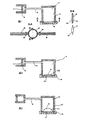
図1の絵1によれば、本発明によるポンプ(汎用ポンプ)の基本原理は、力伝達ユニット2を介して並進ピストン4に動作可能に接続されている駆動ユニット1(電気モータまたは同様の電源)を提供し、前記並進ピストンは、さらに、可変容積の流体チャンバ8を画定するように、吸引/圧力シリンダ6内に支持されている。このシリンダ−流体チャンバ8は、第1流体ライン10を介して第1流体容器12に接続されており、第1圧力チャンバ14が、第1流体容器内に形成されており、第1流体ライン10はその中に通じている。流体チャンバ8、流体ライン10および第1圧力チャンバ14は、たとえば流体チャンバ、流体ラインおよび圧力チャンバへの分割が単に実質的なものである連続した容積であってもよく、それらは、いわば任意に選択することが可能であって、より適切な機能的な説明を可能にする目的に役立つのみである。
According to
例として、第1流体ライン10に体積流量センサ16を設けることができ、第1圧力チャンバ14内に圧力センサ18を設けることができる。ピストン/シリンダユニット4、6、第1流体ライン10および第1圧力チャンバ14(または第1容器12)は、センサ16、18および駆動ユニット1とともに、第1液圧システムS1を定義する。第1液圧システムS1が、たとえば注入ポンプ等、再利用可能な物品の一部である場合、特に有利である。
As an example, a
第1圧力チャンバ14は、たとえば膜または膜状デバイスである第1の可動または変形可能壁20aによって閉鎖され、液圧システムS1の他の壁は剛性が高く、それにより、壁20aが、たとえば外側からの機械的介入によって変形することが妨げられない場合に、圧力チャンバ内の圧力上昇または低下により壁20aの変形のみがもたらされる場合、特に有利である。
The
第2液圧システムS2が、第2容器24内において第2圧力チャンバ22によって定義されており、第2容器24は、第1流体容器12に取り付けられることが可能であるかあるいは取り付けられており、または第1流体容器12内に挿入されることが可能であるかあるいは挿入されている。第2液圧システムS2が、使い捨て物品、たとえば注入セットの一部である場合、特に有利である。例示的な実施形態では、後述するように、使い捨て物品は、たとえば、第2流体ライン26、Yピース32、吸引ライン28および圧力ライン30を含むことができ、弁34および36を再利用可能物品とすることができる。
A second hydraulic system S2 is defined by the
この例示的な実施形態によれば(絶対に必要ではないが)、第2圧力チャンバ22は、膜または膜状デバイス等、第2変形可能壁20bによって閉鎖されている。
According to this exemplary embodiment (although not absolutely necessary), the
さらに、第2圧力チャンバ22は、第2流体ライン26を介して吸引ライン28および圧力ライン30に接続されているかまたは接続されることが可能である。例として、第2流体ライン26は、吸引ライン28を圧力ライン30に接続するTピースまたはYピース32に通じており、弁(逆止弁あるいは電動式2/2方向切換弁、または外側から適用可能なアクチュエータによって圧搾することができるホースセグメント等のような)34、36が、吸引ライン28および圧力ライン30の上および/または中に配置されることが可能であるかまたは配置されている。これらは、能動弁、すなわち、たとえば、所望の流れが、たとえば、注入バッグ(ポンプ吸引側)等の流体供給リザーバまたは容器またはタンク(詳細は示さない)から、宛先(詳細は示さない)、たとえば患者(ポンプ圧力側)に向かう所望の方向に生成されるように制御される弁である場合、特に有利である。これに対する別法として、第2流体ライン26を吸引ライン28および圧力ライン30に選択的に/交互に接続する切換弁等、他の弁構造も考えられる。
Further, the
可動/変形可能な第1分離壁20aを第2分離壁20bに、機械的に可逆式に、たとえば、両方のたとえば膜を本質的にいかなる間隙もなしに接合することができるように、結合することができ、分離壁20bは(たとえば、圧力チャンバ14および22内の上昇した圧力での変形中に/変形のために膜の間に発生する間隙に関して)分離壁20aの動き/変形に従う。
The movable / deformable
上述した概念的構造を備えた、本発明によるポンプの機能原理を、以下のように概説することができる。 The functional principle of the pump according to the invention with the conceptual structure described above can be outlined as follows.
図1の絵1による停止状態では、第2システムS2内のたとえば患者(圧力側)に向かう体積流は、下流弁36が閉鎖位置にあるために遮断される。最初、圧力チャンバ(流体空間)22は、液体および/または気体によって充填されており、最初に脱気することができる。さらなる記述の過程において、簡単のために、液体で充填された本質的に脱気された第2システムS2が想定される。この状態で、第2可動壁、たとえば膜は、たとえば、その(たとえば無負荷の)設計状況にある。第1システムS1もまた、液体および/または気体で充填されている。S1内の流体が、本質的に非圧縮性媒体、または圧縮率曲線が定義されかつ既知である媒体である場合、特に有利である。その時点で、ピストン4を、たとえば、シリンダチャンバ8内の容積が小さい前進位置に位置を定めることができる。第1システムS1は、たとえば、停止状態で本質的に大気圧であり得る。
In the stop state according to
図1の絵2は、本発明によるポンプの吸引状態を示す。この状態では、ピストン4は、駆動ユニット1によって後退しているか、または後退しようとしており、したがって、シリンダチャンバ8の容積が増大している。このピストン4の後退移動の結果として、流体は、第1流体空間14から第1流体ライン10を通ってシリンダチャンバ8内に流れ込み、オプションとして、体積流量をセンサ16によって検出することができる。
Picture 2 in FIG. 1 shows the suction state of the pump according to the invention. In this state, the
第1圧力チャンバ14からの液体の引出しは、第1圧力チャンバ14の容積を低減させることに対応する分離壁20aの運動によって補われる。分離壁20aおよび20bが互いに結合されているため、分離壁20bは分離壁20aの運動に従い、同時に、第2圧力チャンバ22の容積も対応して(たとえば、同じ量の容積という特に有利な方法で)拡大する。その結果、分離壁20bの容積拡大運動に対応して、流体が、(図示せず)供給タンクから吸引ライン28および開放された吸引弁34を介して第2圧力チャンバ22内に吸い込まれる。弁36は、図1の絵2に示すように、この(吸引)段階では閉鎖され続ける。
The withdrawal of liquid from the
ピストン4の移動は、第1流体ライン10を通る体積流量に比例するように、ピストンの断面積を利用して設計される。この体積流量を、センサ16を介して検出し、および/または、たとえば、ピストン4、力伝達ユニット2および/または駆動ユニット1における回転速度および/または経路を測定することによって求めることができる。有利には、駆動ユニットの回転速度またはステップモータのステップ数が、体積流量に対する厳密な基準を確立することも考えられる。
The movement of the
液体の取入れに対応するピストンの後退移動として、第1システムS1において発生する圧力の低下が、第2システムS2の可動壁22の第1圧力チャンバ14内側に向かった変形を引き起こす。ここで、センサ18は、発生した圧力の低下を検出することができ、たとえば、システムS1およびS2ならびに弁34および36の気密性とともに、上述した構成要素またはそれらの流体の圧縮率または順応性、およびたとえば予期を考慮してたとえば分離壁20aおよび20bの接合(の正確さ)もまた検査することができる。同じことがピストンの前方移動に適用される。弁34および36の閉鎖状態でのピストンの特定の前方移動/後方移動等の中間状態(ここでは図示しない)()は、本発明によるポンプ(有利には再利用可能ポンプ)の(特に上述した)構成要素、または本発明の関連する物品(有利には使い捨て物品)の気密性、圧縮率および/または順応性を求めるための圧力上昇または圧力低下を発生させることに利用することができる。これはまた、たとえば、それぞれの流体における気泡等を有利に検出しおよび/または測定する可能性も提供する(他の点では、流体は本質的に非圧縮性であり得る)。たとえば、分離壁に亀裂があることによる漏れを検出しおよび/または測定することも可能である。同様に、ラインのあらゆる下流または上流の閉塞を、対応する弁位置によって検出することも可能である。第1システムS1の圧力チャンバ14と第2システムS2の圧力チャンバ22との間の耐圧力/流体密封結合により、圧力チャンバ22内に流れ込む流体の体積は、ピストン4からシリンダチャンバ8内に移動する(吸引される)体積と厳密に同じである。
As the piston moves backward in response to the liquid intake, the pressure drop generated in the first system S1 causes a deformation of the
図1の絵3によれば、ピストン4は、絵2の方向とは反対の方向にシリンダチャンバ8の容積を低減しつつ移動して、そうすることにより、シリンダチャンバ8から出て第1圧力チャンバ14に入る対応する量の流体を圧搾する。これにより、分離壁20aおよび20bが第2圧力チャンバ(流体空間)22に向かって運動または変形し、結果として、流体が圧力チャンバ22から排出される。
According to picture 3 in FIG. 1, the
この(圧力)段階では、吸引弁34はすでに閉鎖されており、代りに、圧力弁36が開放されており、それにより、第2圧力チャンバ22から流出し圧力ライン30を通り患者に向かう流体の定まった体積流量が存在することになる。この体積流量は、ピストン/シリンダユニット4、6内の排出された(圧搾された)容積に対応する。
At this (pressure) stage, the
分離壁(たとえば膜)の可動性(弾性)に応じて、第2システムS2内に存在する圧力によって重ね合される流体圧力が第1圧力チャンバ14内に蓄積する。ポンプが、たとえば、(図1の絵1による)停止状態にある場合、たとえば、圧力センサ18は、第1システムS1内の圧力を検出することができる。第1システムS1におけるあらゆる圧力変化または脈動は、第2システムS2に直接伝達されかつその逆も可能である。可動分離壁(膜)の好適な設計により、たとえば、回復力が低く、たとえば圧縮率が低く、かつ可撓性が高いことにより、弁34および36の弁位置に応じて、吸引ライン28または圧力ライン30に接続されたシステムにおけるあらゆる変化を確定することも可能である。例として、こうした変化は、たとえば、接続された(かつ排気されていない)注入ガラス瓶の場合、上流側の常に上昇している負圧であり、たとえば接続され流れを鈍らす注入フィルタの場合、下流側の常に上昇している正圧であり得る。
Depending on the mobility (elasticity) of the separation wall (eg membrane), the fluid pressure superimposed by the pressure present in the second system S2 accumulates in the first pressure chamber. For example, when the pump is in a stopped state (according to
(可動分離壁の)上述した記述による2つのシステムS1およびS2の圧力が動的である結合のために、センサ18はまた、ポンプ入口(吸引側)およびポンプ出口(患者側)の両方において、たとえばポンピング段階中に発生するあらゆる圧力変化を検出/確定することができる。このように、(たとえば、あらゆる種類の閉塞、フィルタ、閉鎖したローラクランプ、ねじれたホース等によってもたらされる)上流の分岐と下流分岐におけるあらゆる流れ抵抗を検出することも可能である。
Due to the dynamic coupling of the two systems S1 and S2 according to the above description (of the movable separating wall), the
第1圧力チャンバ14における(または第1液圧システムS1における)、第2圧力チャンバ22における(または第2液圧システムS2における)、上流側で吸引ライン28に液圧式に接続されたシステムにおける、かつ下流側で圧力ライン30に液圧式に接続されたシステムにおけるそれぞれの圧力を測定するかまたは確定することは、たとえば圧力センサ18において関連する圧力信号をゆがめ、たとえば前記分離壁/膜の予張力からおよび/またはたとえば膜のそれぞれの動きあるいは変形に対抗する回復力から発生する可能性がある、分離壁/膜20aおよび20bの寄与が、求められかつ考慮される場合に、改善される。
In a system connected hydraulically to the
たとえば、並進ピストン4の所与の第1位置z1における、この寄与の確定は、たとえば以下のように進めることができる(理想化かつ簡略化されて、例示的な特徴のみ示されている)。
1)たとえば、弁34(上流)を開放し弁36(下流)を閉鎖して、圧力センサ18における圧力信号を測定し、測定値を以下Puと示す。
2)たとえば、弁34(上流)を閉鎖し弁36(下流)を閉鎖して、圧力センサ18における圧力信号を測定し、測定値を以下Pcと示す。
3)たとえば、弁34(上流)を閉鎖し弁36(下流)を開放して、圧力センサ18における圧力信号を測定し、測定値を以下Pdと示す。
幾分か簡略化して、以下のように言える。
1.)Pu(z1)=Psurroundings(周囲圧力)+Pupstream(上流圧力)+Pmembrane contribution(膜圧力寄与)(z1)
2.)Pc(z1)=Psurroundings+Pmembrane contribution(z1)
3.)Pd(z1)=Psurroundings+Pdownstream(下流圧力)+Pmembrane contribution(z1)
For example, the determination of this contribution at a given first position z1 of the
1) For example, the valve 34 (upstream) is opened and the valve 36 (downstream) is closed, and the pressure signal at the
2) For example, the valve 34 (upstream) is closed and the valve 36 (downstream) is closed, the pressure signal at the
3) For example, the valve 34 (upstream) is closed and the valve 36 (downstream) is opened, and the pressure signal at the
Somewhat simplified, it can be said that:
1. ) Pu (z1) = Psurroundings (ambient pressure) + Pupstream (upstream pressure) + Pmembrane contribution (membrane pressure contribution) (z1)
2. ) Pc (z1) = Psurroundings + Pmembrane contribution (z1)
3. ) Pd (z1) = Psurroundings + Pdownstream (downstream pressure) + Pmembrane contribution (z1)
このため、Pupstream=Pu(z1)−Pc(z1)およびPdownstream=Pd(z1)−Pc(z1)を求めることができる。第2ピストン位置z2におけるさらなる類似の測定がさらに使用される場合、たとえば、Pu(z1)−Pu(z2)=Pmembrane contribution(z1)−Pmembrane contribution(z2)により、たとえば、2つのピストン位置z1およびz2における圧力信号に対する膜の寄与の差も求めることができる。 Therefore, Pupstream = Pu (z1) −Pc (z1) and Pdownstream = Pd (z1) −Pc (z1) can be obtained. If further similar measurements at the second piston position z2 are further used, for example, Pu (z1) −Pu (z2) = Pmembrane contribution (z1) −Pmembrane contribution (z2), for example, two piston positions z1 and The difference in membrane contribution to the pressure signal at z2 can also be determined.
ここで採用する式が、(それらの順応性、弁を切り替える順序およびその挙動時間ならびにシステムが持続する挙動時間等、さらなる要素によって具体的に決まる)現実のシステムの正確な記述を表すか否かは重要ではなく、すなわち、異なる弁の組合せかつ場合によってはピストン4(または膜)の異なる位置でたとえば圧力センサ18において圧力信号を測定することが、未知の要素より多くの式が存在する多くの方程式を確立することを可能とし、したがってそれらの式を解くことができ、式に存在する未知の要素(たとえば、環境圧力、システムにおける上流圧力、所定位置における膜回復力×表面積、システムにおける下流圧力等)を求めることができることのみが重要である。
Whether the formula adopted here represents an accurate description of the actual system (specifically determined by further factors such as their adaptability, the order in which the valves are switched and their behavior time and the behavior time the system lasts) Is not important, i.e. measuring the pressure signal at different positions of the piston 4 (or membrane), e.g. at the
当然ながら、第4の弁の組合せ(両方の弁が開放されている)を同様に使用することができる。 Of course, a fourth valve combination (both valves open) can be used as well.
こうしたまたは同様の測定値を使用して、たとえば、たとえば製造中および/またはデバイス保守(検査、自己校正、自己試験等)の間に、再利用可能物品膜20aを「校正する」ことも可能であり、すなわち、その挙動を測定しそれをたとえば再利用可能物品に(たとえば、注入ポンプに)(たとえば永久的に)格納することができる。
These or similar measurements can be used to “calibrate” the
こうしたまたは同様の測定値を使用して、たとえば、たとえば搬送の開始の前に(たとえば、使い捨て物品を注入ポンプに挿入した後、例えば、注入開始の前に)使い捨て物品膜20bの初期「校正」を行うことも可能であり、すなわち、その挙動を測定し、たとえば(たとえば注入ポンプにおける)使い捨て物品内に(たとえば、この使い捨て物品の適用の期間にわたって一時的に)保管することができる。 Using these or similar measurements, an initial “calibration” of the disposable article membrane 20b, for example, prior to the start of delivery (eg, after inserting the disposable article into the infusion pump, eg, prior to infusion). Can be measured, i.e. its behavior can be measured and stored in a disposable article (e.g. in an infusion pump) (e.g. temporarily over the period of application of the disposable article).
こうしたまたは同様の測定を、たとえば動作中に実施することも可能であり、ここでは、有利には、たとえば、吸引段階(絵2−Puに対応)と排出段階(絵3−Pdに対応)との間の、たとえばPcに対応することができる中間段階(本明細書には示さない)に導入することが可能である。さらに、変量を求めるために、種々のピストン位置で測定値を使用することができるために、ピストンを、これらの中間段階において前方および/または後方に移動させることも可能である。 Such or similar measurements can also be carried out, for example during operation, where, for example, advantageously, for example, a suction phase (corresponding to picture 2-Pu) and a draining stage (corresponding to picture 3-Pd) Can be introduced at an intermediate stage (not shown here), for example, which can correspond to Pc. Furthermore, since the measurements can be used at various piston positions to determine the variables, it is also possible to move the pistons forward and / or backward in these intermediate stages.
また、S1、S2ならびに上流分岐および下流分岐においてS2に接続されたシステムの間のいかなる圧力差も、たとえばこうした中間段階中に、たとえば弁34および36を閉鎖させて、ピストン4の対応する移動によって等化され、これらのかつ同様の手続きにより、特に上流および下流の上述した液圧分岐のすべてにおいて非常に均一な圧力プロファイルを確立することが可能になる、ということが特に有利である。したがって、非常に均一な搬送プロファイルを同様に達成することができる。さらに、有効な範囲で達成可能な精度が著しく向上する。さらに、均一な圧力プロファイルにより、流体における脱気および/またはマイクロバブルからマクロバブルへの凝集が低減する。
Also, any pressure difference between S1, S2 and the system connected to S2 in the upstream and downstream branches may result from a corresponding movement of the
ポンピング作用に対して重要な変量の実質的にすべてを、1つの単一圧力センサ18および2つの弁34および36によって検査し制御することができることが特に有利である。
It is particularly advantageous that substantially all of the variables important to the pumping action can be inspected and controlled by one
優れた利点はまた、搬送の開始前、搬送中および/または搬送の終了後に、たとえば(たとえば材料の疲労および/または欠陥による)膜の性能のあり得る変化を検出しおよび/または補正する可能性によっても表される。したがって、こうした手法により、同様に包括的な自己試験が可能になる。 A great advantage is also the possibility to detect and / or correct possible changes in the performance of the film (for example due to material fatigue and / or defects) before, during and / or after transfer. Also represented by Thus, this approach allows for a comprehensive self-test as well.
検出可能なシステムの変化の例は以下である。すなわち、上流流体源あるいは下流流体シンクおよび/または再利用可能物品等の高さレベルの変化、たとえば上流および/または下流の流れ抵抗の変化(したがって、たとえばライン閉塞および/または漏れ)、たとえば下流の逆圧(たとえば、同様に患者の血圧等)、第1液圧システムおよび/または第2液圧システムにおける漏れ、材料疲労および/またはたとえば、分離壁20aおよび/または20bにおける亀裂および/または穴等の欠陥、ただしまた、たとえば流体の変化(たとえば、注入液の新たな組成によるおよび/またはたとえばS1および/あるいはS2における気泡による変化)である。一方、圧力センサ信号の妥当性もまた検査することができ、これにより、圧力センサの機能性を検査することができる。
Examples of detectable system changes are: That is, changes in height levels, such as upstream fluid sources or downstream fluid sinks and / or reusable articles, such as upstream and / or downstream flow resistance changes (and thus, for example, line blockage and / or leakage), such as downstream Back pressure (eg as well as patient blood pressure, etc.), leaks in the first hydraulic system and / or second hydraulic system, material fatigue and / or cracks and / or holes in the
図1の絵3によるポンピングまたは排出段階に続いて、ポンプは再び、図1の絵2による吸引段階に変化し、吸引と排出との間の段階変化は、好ましくは連続的にまたは間隔をあけて繰り返される。特に、連続的な繰返しの場合、ここでは、特に下流側(ポンプ圧力側)に対して妨害する影響を与える可能性がある固有のデッド段階が、ピストン4の異なる動き速度(高い吸引速度/低い排出速度)によって最小化されるという点で、不連続の体積流量を低減するかまたは大幅に回避することができる。さらに、デッド段階(「後退段階」、「負荷段階」、「吸引段階」)の間、本発明に対応する第2ポンプが移送作業を行いその逆も可能である(いわば、二重または2ピストンポンプ)ように、原理を拡張することも可能である。 Following the pumping or draining phase according to picture 3 in FIG. 1, the pump again changes to the suction phase according to picture 2 in FIG. 1, and the phase change between suction and drainage is preferably continuous or spaced. Repeated. In particular, in the case of continuous repetition, here the inherent dead phase, which can have a disturbing effect, in particular on the downstream side (pump pressure side), is the different movement speed of the piston 4 (high suction speed / low Discontinuous volumetric flow can be reduced or largely avoided in that it is minimized by (discharge rate). Furthermore, during the dead phase ("reverse phase", "load phase", "suction phase"), the second pump corresponding to the present invention performs the transfer operation and vice versa (so to speak, double or two pistons). It is possible to extend the principle as well.
同様に図1から理解することができるように、少なくとも、別個の構成要素として、特に使い捨て物品として膜(可動分離壁)20bを含む第2流体容器24を実施し、好ましくは、第2システムS2全体が使い捨て物品として提供されることが有利であることが表される。これは、この場合、第2容器24を、第1圧力チャンバ14内の圧力変化により分離壁20aおよび20bの補償運動、したがって第2圧力チャンバ22の容積の変化がもたらされるように、分離可能であるように(たとえば、可逆可能に)第1容器12に結合してよいことを意味する。
Similarly, as can be seen from FIG. 1, at least a second
例として、両容器を、互いに差し込みおよび/または互いにねじ込みおよび/または押し付けることができる。これらの容器を、同様に互いにフランジ状に取り付ける(flange)ことができる。各々が第1圧力チャンバおよび第2圧力チャンバをそれぞれ封止する、2つのたとえば平行な分離壁/膜が設けられるため、2つの容器を取り除く間に圧力チャンバを空にする必要はない。 By way of example, both containers can be plugged into each other and / or screwed and / or pressed together. These containers can likewise be flanged together. There is no need to empty the pressure chamber between the removal of the two containers since two, eg, parallel separation walls / membranes are provided, each sealing the first pressure chamber and the second pressure chamber, respectively.
以下、図2および図3に基づいて、上述したポンプ原理の具体的な技術的実施態様について技術的に言及する。 Hereinafter, a specific technical embodiment of the above-described pump principle will be technically referred to based on FIG. 2 and FIG.
特に滅菌条件下で搬送プロセスが行われる場合、使い捨て物品の概念は、容器24を含む第2システムS2全体に関連しないが、たとえば、特に第2容器に適合され、いわば前記容器の裏当てを形成する要素に限定される場合にもまた、有利であり得る。
The concept of disposable articles is not relevant to the entire second system S2 including the
図2の絵1および絵2によれば、実際の第2流体圧力チャンバが、いわば、たとえば流体受入体としての(たとえば、注入)ホース40によって形成されており、ホース40は、第2容器24内に挿入されることが可能であり、形状適合式に可動分離壁/膜20aに結合されている。これは、ホース40の壁が第2分離壁/膜20bに対応し、ホースの材料が、十分に可撓性が高く/変形可能である場合、分離壁20aが形状に対応するようにホース40を変形させることができ、それにより、たとえば比例する体積流量を生成することができることを意味する。この理由で、ホース40を(たとえば、それに接続された吸引ライン28/圧力ライン30、および場合によっては同様に弁34、36とともに)使い捨て物品として実施するだけでよい。
According to
代替的にかつ例として、図3の絵1〜絵3によれば、第2容器24内にクッション状はめ込み材42が(たとえば緩く)配置されている。設計(たとえば、圧力なし)によって事前定義された位置では、たとえばバッグ状クッション42が、第2容器と同じ体積を有することができ(第2容器を完全に充填する)、たとえば、縁が流体密封式にたとえばプレート46に固定されている可撓性/弾性フォイル/膜44から構成され得る(有利には、使い捨て物品は、たとえば、そのハウジングが第1容器12に固定しておよび/または可逆的におよび/または緊密に取り付けられることが可能であることにより、第2容器24の機能をすでにカバーしており、たとえば、第2容器24に対する追加の構成要素が不要であるという利点がある、ということも可能である)。第2流体ライン26に対する(それ以上詳述しない)少なくとも1つの開口部が、このように形成されたバッグの内部空間(第2圧力チャンバ)内に通じている。この開口部を、たとえばプレート46に形成することができる。しかしながら、2つ以上の入口、たとえば1つは供給ライン28用、1つは排出ライン30用を設けることも可能である。これに関して、プレート46を用いる代りに、バッグを専ら可撓性材料で作製することができるという事実が留意される。この実施形態により、可動分離壁20aの運動はバッグ42に直接伝達され、バッグ42はそれに対応して容積が変化する。
Alternatively and by way of example, according to
上述した例示的な実施形態は、本発明によるポンプの機能のモードを単純に論証することができるように選択されている。したがって、それらは、必ずしも、実施態様の実際の形態に対応しているとは限らない。例として、別個の部品の形態で例示されたピストン/シリンダユニットは、すでに第1容器の構成要素であり得る。ピストン/シリンダユニットのピストンが、2つ以上の第1システムに液体を充填し、またそれらを空にすることも考えられるし、第2システムが各々に当該システムに接続されることが可能であるかまたは接続されていることも考えられる。これは、たとえば、単一システムを備えた上述した例示的な実施形態におけるデッド段階が、(対応する段階シフトを含んで)並列に接続されたいくつかのシステムに用いることにより最小化される場合に、意味をなす。 The exemplary embodiment described above is chosen so that it can simply demonstrate the mode of functioning of the pump according to the invention. Therefore, they do not necessarily correspond to the actual form of the embodiment. As an example, the piston / cylinder unit illustrated in the form of a separate part may already be a component of the first container. It is conceivable for the pistons of the piston / cylinder unit to fill two or more first systems with liquid and empty them, and it is possible for each second system to be connected to that system. Or it may be connected. This can be minimized, for example, by using the dead stage in the exemplary embodiment described above with a single system for several systems connected in parallel (including the corresponding stage shift). Makes sense.
ピストン/シリンダユニットは、単に例示的な解決法を表すこともまた留意されるべきである。斜板ポンプ、ベーンポンプ、ギアポンプ等のあらゆるあり得るポンピング方法を適用することができることも考えられる。本質的に十分な体積流量精度を可能にしないこうしたポンピングユニット(メンブレンポンプ等)は、本発明に従って、制御技術による所望の精度をもたらすように、たとえば体積流量センサおよび/または質量流量センサ等とともに備えられても良い。 It should also be noted that the piston / cylinder unit represents merely an exemplary solution. It is also conceivable that all possible pumping methods such as swash plate pumps, vane pumps, gear pumps etc. can be applied. Such a pumping unit (such as a membrane pump) that essentially does not allow sufficient volumetric flow accuracy is provided with, for example, a volumetric flow sensor and / or a mass flow sensor, etc., according to the present invention, to provide the desired accuracy by the control technique. May be.
以下の項目は、国際出願時の請求の範囲に記載の要素である。 The following items are the elements described in the claims at the time of international application.
(項目1)(Item 1)
電動ポンピングユニット(4、6)と、第1流体空間(14)と、可動および/または変形可能な第1分離壁(20a)とからなり、ポンピングユニット(4、6)は、当該第1流体空間に流体を給送し及び当該第1流体空間から流体を除去することができる、第1流体システム(S1)と、 An electric pumping unit (4, 6), a first fluid space (14), and a movable and / or deformable first separation wall (20a) are formed. The pumping unit (4, 6) includes the first fluid. A first fluid system (S1) capable of delivering fluid to the space and removing fluid from the first fluid space;
前記第1流体システム(S1)に結合されることが可能である第2流体システム(S2)であって、第2流体空間(22)と、前記第1流体空間(14)における容積および/または圧力の変化が前記第2流体空間(22)における容積および圧力に対して本質的に予測可能な、および/または、確定可能な影響を有するように、前記第1分離壁(20a)に機械的にまたは流体的に結合されることが可能である可動および/または変形可能な第2分離壁(20b)と、を含んでいる第2流体システム(S2)と、 A second fluid system (S2) that can be coupled to the first fluid system (S1), the second fluid space (22) and the volume in the first fluid space (14) and / or Mechanical to the first separation wall (20a) such that a change in pressure has an essentially predictable and / or deterministic effect on the volume and pressure in the second fluid space (22). A second fluid system (S2) including a movable and / or deformable second separation wall (20b) that can be coupled to or fluidly;
を備える医療用流体搬送デバイス。A medical fluid delivery device comprising:
(項目2)(Item 2)
前記第2流体空間(22)に接続され、かつ関連する弁手段(34)を備える少なくとも1つの吸引ライン(28)と、 At least one suction line (28) connected to said second fluid space (22) and comprising associated valve means (34);
前記第2流体空間(22)に接続され、かつ関連する弁手段(36)を備える少なくとも1つの圧力ライン(30)と、 At least one pressure line (30) connected to said second fluid space (22) and comprising associated valve means (36);
前記第1流体システム(S1)において生成され、確定されかつ制御されることが可能である前記第2流体システム(S2)の前記吸引ラインから前記圧力ライン内への体積流量および/または質量流量、および/または、その逆方向に流れる体積流量および/または質量流量と、 Volume flow and / or mass flow into the pressure line from the suction line of the second fluid system (S2), which can be generated, determined and controlled in the first fluid system (S1), And / or volume flow and / or mass flow in the opposite direction;
を特徴とする請求項1に記載の医療用流体搬送デバイス。The medical fluid delivery device according to
(項目3)(Item 3)
両分離壁(20a、20b)は、膜または膜状分離壁であることを特徴とする、請求項1に記載の医療用流体搬送デバイス。 The medical fluid transport device according to
(項目4)(Item 4)
上流弁(34)が開放され下流弁(36)が閉鎖された状態において、前記第1流体空間(14)における流体体積がΔV低減することは、本質的に、前記第2流体空間(22)における流体体積がΔV拡大すること引き起こし、当該流体体積ΔVが、上流点において吸引ライン(28)に接続されている流体システムから本質的に取り出されることを特徴とする、請求項1〜3のいずれか一項に記載の医療用流体搬送デバイス。 In a state where the upstream valve (34) is opened and the downstream valve (36) is closed, the fluid volume in the first fluid space (14) is reduced by ΔV in essence, the second fluid space (22). 4. The fluid volume at V is increased by ΔV, which fluid volume ΔV is essentially taken from the fluid system connected to the suction line (28) at the upstream point. The medical fluid transport device according to
(項目5)(Item 5)
上流弁(34)が閉鎖され下流弁(36)が開放された状態において、前記第1流体空間(14)における流体体積がΔV拡大することは、本質的に、前記第2流体空間(22)における流体体積がΔV低減することを引き起こし、当該流体体積ΔVが、下流点において圧力ライン(30)に接続されている流体システムに本質的に追加されることを特徴とする、請求項1〜4のいずれか一項に記載の医療用流体搬送デバイス。 In the state where the upstream valve (34) is closed and the downstream valve (36) is opened, the increase in the fluid volume in the first fluid space (14) by ΔV is essentially the second fluid space (22). The fluid volume at is caused to be reduced by ΔV, which fluid volume ΔV is essentially added to the fluid system connected to the pressure line (30) at the downstream point. The medical fluid conveyance device according to any one of the above.
(項目6)(Item 6)
前記第1流体空間(14)に液圧式におよび/または空気圧式に接続されている少なくとも1つの圧力センサ(18)を備えることを特徴とする、請求項1〜5のいずれか一項に記載の医療用流体搬送デバイス。 6. The at least one pressure sensor (18) connected hydraulically and / or pneumatically to the first fluid space (14), according to any one of the preceding claims. Medical fluid delivery device.
(項目7)(Item 7)
前記第1流体システム(S16)に少なくとも1つの体積流量センサおよび/または質量流量センサを備え、当該センサは、ある期間の間に流体空間(14)に追加されまたはそこから除去される流体体積を求めることができることを特徴とする、請求項6に記載の医療用流体搬送デバイス。 The first fluid system (S16) comprises at least one volume flow sensor and / or a mass flow sensor, which sensor adds or removes fluid volume from the fluid space (14) during a period of time. The medical fluid delivery device according to
(項目8)(Item 8)
少なくとも部分的に可撓性があり、かつ、可動な前記分離壁(20a)と接触している前記第2分離壁(20b)を形成するように前記第2流体空間(22)に挿入されることができる流体受入体(40)であって、前記弁手段(34、36)が流体的に接続されている流体受入体(40)による特徴を有する請求項1〜7のいずれか一項に記載の医療用流体搬送デバイス。 Inserted into the second fluid space (22) to form the second separation wall (20b) in contact with the separation wall (20a) that is at least partially flexible and movable. 8. Fluid receiving body (40) capable of being characterized by a fluid receiving body (40) to which the valve means (34, 36) are fluidly connected. The medical fluid delivery device as described.
(項目9)(Item 9)
前記可撓性流体受入体(40)は、少なくとも部分的に可撓性がある医療用ホースまたはバッグである、請求項8に記載の医療用流体搬送デバイス。 The medical fluid delivery device of claim 8, wherein the flexible fluid receiver (40) is a medical hose or bag that is at least partially flexible.
(項目10)(Item 10)
前記第1流体空間(14)が第1容器(12)内に形成され、前記第2流体空間(22)が、前記可動分離壁(20a、20b)を間に挟んで前記第1容器(12)に機械的に接続される第2容器(24)内に形成されていることを特徴とする、請求項1〜9のいずれか一項に記載の医療用流体搬送デバイス。 The first fluid space (14) is formed in the first container (12), and the second fluid space (22) is interposed between the movable separation walls (20a, 20b) and the first container (12). 10. The medical fluid delivery device according to any one of
(項目11)(Item 11)
前記第2システム(S2)が、全体として使い捨て品として設計されており、または、前記第2システム(S2)の少なくともそれらの構成要素が、流体に直接接触する使い捨て品として設計されていることを特徴とする、請求項1〜10のいずれか一項に記載の医療用流体搬送デバイス。 The second system (S2) is designed as a disposable item as a whole, or at least those components of the second system (S2) are designed as a disposable item in direct contact with the fluid. The medical fluid delivery device according to any one of
(項目12)(Item 12)
前記2つの分離壁(20a、20b)の結合は、少なくとも両分離壁の部分的領域によっても境界が定められる分離壁の間の空間における圧力を検査し制御することによって、影響され、支持され、維持され、改善され、検査され、および/または解放されるように設計されていることを特徴とする、請求項1に記載の医療用流体搬送デバイス。 The coupling of the two separation walls (20a, 20b) is influenced and supported by inspecting and controlling the pressure in the space between the separation walls, which is also bounded by at least a partial region of both separation walls, The medical fluid delivery device of
(項目13)(Item 13)
請求項1〜12のいずれか一項に記載の医療用流体ポンプの前記第2流体空間(22)を画定し、使い捨て品として提供される交換可能な流体受入体であって、少なくとも組み立てられた状態で流体密封式に前記流体受入体または容器(12、40)を閉鎖する少なくとも1つの可撓性外壁(20b、40)による特徴を有する流体受入体。 13. A replaceable fluid receptacle that defines the second fluid space (22) of the medical fluid pump according to any one of claims 1-12 and is provided as a disposable, at least assembled. A fluid receiving body characterized by at least one flexible outer wall (20b, 40) closing said fluid receiving body or container (12, 40) in a fluid-tight manner.
1 駆動ユニット
2 力伝達ユニット
4 並進ピストン
6 シリンダ
8 流体チャンバ
10 流体ライン
12 第1流体容器
14 第1流体圧力チャンバ
16 体積流量センサ
18 圧力センサ
20a、20b 分離壁
22 第2流体圧力チャンバ
24 第2容器
26 第2流体ライン
28 吸引ライン
30 圧力ライン
32 Yピース
34、36 逆止め弁
40 流体受入体/ホース
42 はめ込み材/クッション
44 フォイル/膜
46 プレート
DESCRIPTION OF
Claims (9)
前記第1流体システム(S1)に結合されることが可能である第2流体システム(S2)であって、第2流体空間(22)と、前記第1流体空間(14)における容積および/または圧力の変化が前記第2流体空間(22)における容積および圧力に対して本質的に予測可能な、および/または、確定可能な影響を有するように、前記第1分離壁(20a)の動きおよび/または変形に従って可動および/または変形可能な第2分離壁(20b)と、を含んでいる第2流体システム(S2)と、
少なくとも部分的に可撓性があり、かつ、可動な前記第1分離壁(20a)と接触している前記第2分離壁(20b)を形成するように前記第2流体空間(22)を含む流体受入体(40)であって、弁手段(34、36)が流体的に接続されている流体受入体(40)と、
を備えるとともに、
前記可撓性流体受入体(40)は、医療用ホースであり、
前記ポンピングユニット(4、6)によって、前記流体が当該第1流体空間(14)から除去されると、液体が前記流体受入体(40)内に吸引され、
前記ポンピングユニット(4、6)によって、前記流体が当該第1流体空間(14)に給送されると、前記液体が前記流体受入体(40)の外に排出される、
医療用流体搬送デバイス。 An electric pumping unit (4, 6) comprising a piston (4) moving in a cylinder (6), a first fluid space (14) and a movable and / or deformable first separation wall (20a); The pumping unit (4, 6) is configured to supply a fluid to the first fluid space and remove a fluid from the first fluid space; a first fluid system (S1);
A second fluid system (S2) that can be coupled to the first fluid system (S1), the second fluid space (22) and the volume in the first fluid space (14) and / or The movement of the first separation wall (20a) and so that the change in pressure has an essentially predictable and / or deterministic effect on the volume and pressure in the second fluid space (22); A second fluid system (S2) comprising: a second separation wall (20b) movable and / or deformable according to / or deformation;
The second fluid space (22) is included to form the second separation wall (20b) in contact with the first separation wall (20a) that is at least partially flexible and movable. A fluid receiver (40), wherein the valve means (34, 36) are fluidly connected;
With
The flexible fluid receiver (40) is a medical hose;
When the fluid is removed from the first fluid space (14) by the pumping unit (4, 6), liquid is sucked into the fluid receiver (40),
When the fluid is fed to the first fluid space (14) by the pumping unit (4, 6), the liquid is discharged out of the fluid receiving body (40).
Medical fluid delivery device.
前記第2流体空間(22)に接続され、かつ関連する弁手段(36)を備える少なくとも1つの圧力ライン(30)と、を備え、
前記第2流体システム(S2)の前記吸引ラインから前記圧力ライン内への体積流量および/または質量流量、および/または、その逆方向に流れる体積流量および/または質量流量が、前記第1流体システム(S1)において生成され、確定されかつ制御されることが可能であることを特徴とする、請求項1に記載の医療用流体搬送デバイス。 At least one suction line (28) connected to said second fluid space (22) and comprising associated valve means (34);
At least one pressure line (30) connected to said second fluid space (22) and comprising associated valve means (36),
Volume flow and / or mass flow from the suction line into the pressure line and / or volume flow and / or mass flow in the opposite direction of the second fluid system (S2) is the first fluid system. The medical fluid delivery device of claim 1 , wherein the medical fluid delivery device can be generated, determined and controlled in (S1).
Applications Claiming Priority (3)
| Application Number | Priority Date | Filing Date | Title |
|---|---|---|---|
| DE102012113087.6 | 2012-12-24 | ||
| DE102012113087.6A DE102012113087A1 (en) | 2012-12-24 | 2012-12-24 | Pump for medical purposes |
| PCT/EP2013/077950 WO2014102259A1 (en) | 2012-12-24 | 2013-12-23 | Pump for medical purposes |
Publications (3)
| Publication Number | Publication Date |
|---|---|
| JP2016504105A JP2016504105A (en) | 2016-02-12 |
| JP2016504105A5 JP2016504105A5 (en) | 2017-02-02 |
| JP6433431B2 true JP6433431B2 (en) | 2018-12-05 |
Family
ID=49998207
Family Applications (1)
| Application Number | Title | Priority Date | Filing Date |
|---|---|---|---|
| JP2015548674A Active JP6433431B2 (en) | 2012-12-24 | 2013-12-23 | Medical pump |
Country Status (8)
| Country | Link |
|---|---|
| US (1) | US10076604B2 (en) |
| EP (1) | EP2788046B1 (en) |
| JP (1) | JP6433431B2 (en) |
| CN (1) | CN104870035B (en) |
| DE (1) | DE102012113087A1 (en) |
| ES (1) | ES2609528T3 (en) |
| RU (1) | RU2666586C2 (en) |
| WO (1) | WO2014102259A1 (en) |
Families Citing this family (10)
| Publication number | Priority date | Publication date | Assignee | Title |
|---|---|---|---|---|
| DE102014013152A1 (en) * | 2014-09-04 | 2016-03-10 | Fresenius Medical Care Deutschland Gmbh | A method for determining a system compressibility value of a medical diaphragm pump drive |
| JP7035041B2 (en) * | 2016-11-01 | 2022-03-14 | サノフィ-アベンティス・ドイチュラント・ゲゼルシャフト・ミット・ベシュレンクテル・ハフツング | Volume measuring device |
| DE102016015110A1 (en) | 2016-12-20 | 2018-06-21 | Fresenius Medical Care Deutschland Gmbh | Positive displacement pump for medical fluids and blood treatment device with a positive displacement pump for medical fluids and method for controlling a positive displacement pump for medical fluids |
| EP3638332A1 (en) | 2017-06-14 | 2020-04-22 | Smith & Nephew, Inc | Fluid removal management and control of wound closure in wound therapy |
| US11395873B2 (en) | 2017-06-14 | 2022-07-26 | Smith & Nephew, Inc. | Control of wound closure and fluid removal management in wound therapy |
| US10814062B2 (en) * | 2017-08-31 | 2020-10-27 | Becton, Dickinson And Company | Reservoir with low volume sensor |
| US10850026B2 (en) * | 2018-05-08 | 2020-12-01 | Carefusion Corporation | Peristaltic pump of an infusion system for delivery of small volumes of fluid |
| CN109172963B (en) * | 2018-10-19 | 2021-05-14 | 青岛大学附属医院 | Atomization physical therapy instrument with continuous administration function |
| US20200200313A1 (en) * | 2018-12-19 | 2020-06-25 | Boston Scientific Scimed, Inc. | Dampening element for fluid management system |
| DE202022104589U1 (en) | 2022-08-12 | 2023-11-16 | Fresenius Medical Care Deutschland Gmbh | Diaphragm pump drive |
Family Cites Families (19)
| Publication number | Priority date | Publication date | Assignee | Title |
|---|---|---|---|---|
| ZA726230B (en) | 1971-09-28 | 1973-05-30 | Bestnu Eng Ltd | Intravenous fluids administration apparatus |
| US4382753A (en) * | 1979-03-09 | 1983-05-10 | Avi, Inc. | Nonpulsating IV pump and disposable pump chamber |
| DE3428828A1 (en) | 1984-08-04 | 1986-02-13 | Karl-Theo 6652 Bexbach Braun | DEVICE FOR CONVEYING MECHANICAL STRESS HIGH-SENSITIVE LIQUIDS |
| US5207645A (en) | 1991-06-25 | 1993-05-04 | Medication Delivery Devices | Infusion pump, treatment fluid bag therefor, and method for the use thereof |
| JPH08508173A (en) * | 1992-11-02 | 1996-09-03 | メディケーション デリバリー デバイシイズ インク | Medical drip pump, drip bag and their use |
| EP0957954B1 (en) * | 1996-11-22 | 2003-05-28 | Therakos, Inc. | Apparatus for pumping fluid at a steady flow rate |
| DE19919572C2 (en) * | 1999-04-29 | 2002-04-18 | Fresenius Medical Care De Gmbh | Method and device for determining gas in medical liquids |
| US6877713B1 (en) | 1999-07-20 | 2005-04-12 | Deka Products Limited Partnership | Tube occluder and method for occluding collapsible tubes |
| US6250502B1 (en) | 1999-09-20 | 2001-06-26 | Daniel A. Cote | Precision dispensing pump and method of dispensing |
| SE520340C2 (en) | 2002-03-14 | 2003-06-24 | Billy Nilson | Ambulatory diaphragm pump |
| US6929751B2 (en) * | 2002-05-24 | 2005-08-16 | Baxter International Inc. | Vented medical fluid tip protector methods |
| WO2006000415A1 (en) | 2004-06-24 | 2006-01-05 | E-Z-Em, Inc. | Hydraulic injection system and injection method |
| WO2007092637A2 (en) | 2006-02-09 | 2007-08-16 | Deka Products Limited Partnership | Patch-sized fluid delivery systems and methods |
| US8087906B2 (en) | 2007-08-01 | 2012-01-03 | Carefusion 303, Inc. | Fluid pump with disposable component |
| EP2263720B1 (en) * | 2007-08-20 | 2012-06-13 | Mallinckrodt LLC | Fluid driven medical injectors |
| IL190335A0 (en) | 2008-03-20 | 2009-09-22 | Gaia Med Ltd | Miniature disposable or partially reusable dosing pumps |
| EP2323716B1 (en) | 2008-05-08 | 2015-03-04 | MiniPumps, LLC | Drug-delivery pumps |
| DE102010005746A1 (en) * | 2010-01-26 | 2011-07-28 | Fresenius Medical Care Deutschland GmbH, 61352 | Medical device |
| DE102010007464B4 (en) * | 2010-02-10 | 2016-09-29 | Fresenius Medical Care Deutschland Gmbh | Medical functional device, treatment device and method |
-
2012
- 2012-12-24 DE DE102012113087.6A patent/DE102012113087A1/en not_active Withdrawn
-
2013
- 2013-12-23 JP JP2015548674A patent/JP6433431B2/en active Active
- 2013-12-23 US US14/653,167 patent/US10076604B2/en active Active
- 2013-12-23 WO PCT/EP2013/077950 patent/WO2014102259A1/en active Application Filing
- 2013-12-23 ES ES13821827.6T patent/ES2609528T3/en active Active
- 2013-12-23 CN CN201380067766.5A patent/CN104870035B/en active Active
- 2013-12-23 EP EP13821827.6A patent/EP2788046B1/en active Active
- 2013-12-23 RU RU2015130618A patent/RU2666586C2/en active
Also Published As
| Publication number | Publication date |
|---|---|
| RU2666586C2 (en) | 2018-09-11 |
| CN104870035B (en) | 2018-06-15 |
| WO2014102259A1 (en) | 2014-07-03 |
| JP2016504105A (en) | 2016-02-12 |
| EP2788046A1 (en) | 2014-10-15 |
| RU2015130618A (en) | 2017-01-27 |
| EP2788046B1 (en) | 2016-11-02 |
| ES2609528T3 (en) | 2017-04-20 |
| US20150328399A1 (en) | 2015-11-19 |
| US10076604B2 (en) | 2018-09-18 |
| DE102012113087A1 (en) | 2014-07-10 |
| CN104870035A (en) | 2015-08-26 |
Similar Documents
| Publication | Publication Date | Title |
|---|---|---|
| JP6433431B2 (en) | Medical pump | |
| JP6195825B2 (en) | Method and apparatus for measuring gas in a liquid transported by a pump device | |
| JP2952037B2 (en) | High pressure fluid measurement control device | |
| US9459128B2 (en) | Device and method for dispensing or receiving a liquid volume | |
| US9757517B2 (en) | Piston pump | |
| US11110218B2 (en) | Surgical cartridge, pump and surgical operating machine | |
| JP5404615B2 (en) | Pump module for use in a chemical dosing system | |
| US11291753B2 (en) | Determining a volume of medical fluid pumped into or out of a medical fluid cassette | |
| CN107073185A (en) | The determination method of the system compresses rate value of medical films pump controller | |
| MX2012001030A (en) | System and method for pumping intravenous fluid. | |
| CN105307703A (en) | Pneumatically coupled direct drive fluid control system and process | |
| JP7123968B2 (en) | A positive displacement pump for medical fluids and a blood processing apparatus comprising a positive displacement pump for medical fluids and a method for controlling a positive displacement pump for medical fluids | |
| JP2014526008A (en) | Method and system for malfunction detection of MEMS micropumps | |
| CN107802918A (en) | A kind of dynamic action is in the transfusion control method and control system of decoction soft bag | |
| JP7387441B2 (en) | Pump systems, dialysis machines, and methods of operating pump systems | |
| US20230366388A1 (en) | Dual active valve fluid pressure operated positive displacement pump | |
| US20220236127A1 (en) | Pressure sensing device and blood purification apparatus using same | |
| CN109715227B (en) | System for measuring the amount of liquid in an elastic pouch | |
| CN209827803U (en) | Infusion system composed of air as power device | |
| GB2431439A (en) | Volumetric dosing apparatus | |
| BR112015014058B1 (en) | MEDICAL FLUID CARRIER DEVICE AND EXCHANGEABLE FLUID RECEIVING BODY OF A MEDICAL FLUID PUMP | |
| US10030674B2 (en) | Sterile liquid pump with single use elements |
Legal Events
| Date | Code | Title | Description |
|---|---|---|---|
| A521 | Request for written amendment filed |
Free format text: JAPANESE INTERMEDIATE CODE: A523 Effective date: 20161012 |
|
| A621 | Written request for application examination |
Free format text: JAPANESE INTERMEDIATE CODE: A621 Effective date: 20161012 |
|
| A871 | Explanation of circumstances concerning accelerated examination |
Free format text: JAPANESE INTERMEDIATE CODE: A871 Effective date: 20161012 |
|
| A975 | Report on accelerated examination |
Free format text: JAPANESE INTERMEDIATE CODE: A971005 Effective date: 20161125 |
|
| A521 | Request for written amendment filed |
Free format text: JAPANESE INTERMEDIATE CODE: A523 Effective date: 20161214 |
|
| A871 | Explanation of circumstances concerning accelerated examination |
Free format text: JAPANESE INTERMEDIATE CODE: A871 Effective date: 20161214 |
|
| A975 | Report on accelerated examination |
Free format text: JAPANESE INTERMEDIATE CODE: A971005 Effective date: 20161222 |
|
| A131 | Notification of reasons for refusal |
Free format text: JAPANESE INTERMEDIATE CODE: A131 Effective date: 20170207 |
|
| A601 | Written request for extension of time |
Free format text: JAPANESE INTERMEDIATE CODE: A601 Effective date: 20170502 |
|
| A521 | Request for written amendment filed |
Free format text: JAPANESE INTERMEDIATE CODE: A523 Effective date: 20170707 |
|
| A131 | Notification of reasons for refusal |
Free format text: JAPANESE INTERMEDIATE CODE: A131 Effective date: 20171003 |
|
| A02 | Decision of refusal |
Free format text: JAPANESE INTERMEDIATE CODE: A02 Effective date: 20180123 |
|
| A521 | Request for written amendment filed |
Free format text: JAPANESE INTERMEDIATE CODE: A523 Effective date: 20180523 |
|
| A911 | Transfer to examiner for re-examination before appeal (zenchi) |
Free format text: JAPANESE INTERMEDIATE CODE: A911 Effective date: 20180531 |
|
| A131 | Notification of reasons for refusal |
Free format text: JAPANESE INTERMEDIATE CODE: A131 Effective date: 20180703 |
|
| A521 | Request for written amendment filed |
Free format text: JAPANESE INTERMEDIATE CODE: A523 Effective date: 20180928 |
|
| TRDD | Decision of grant or rejection written | ||
| A01 | Written decision to grant a patent or to grant a registration (utility model) |
Free format text: JAPANESE INTERMEDIATE CODE: A01 Effective date: 20181016 |
|
| A61 | First payment of annual fees (during grant procedure) |
Free format text: JAPANESE INTERMEDIATE CODE: A61 Effective date: 20181106 |
|
| R150 | Certificate of patent or registration of utility model |
Ref document number: 6433431 Country of ref document: JP Free format text: JAPANESE INTERMEDIATE CODE: R150 |
|
| R250 | Receipt of annual fees |
Free format text: JAPANESE INTERMEDIATE CODE: R250 |
|
| R250 | Receipt of annual fees |
Free format text: JAPANESE INTERMEDIATE CODE: R250 |