JP6431890B2 - System and method for conveying a moving object - Google Patents
System and method for conveying a moving object Download PDFInfo
- Publication number
- JP6431890B2 JP6431890B2 JP2016244123A JP2016244123A JP6431890B2 JP 6431890 B2 JP6431890 B2 JP 6431890B2 JP 2016244123 A JP2016244123 A JP 2016244123A JP 2016244123 A JP2016244123 A JP 2016244123A JP 6431890 B2 JP6431890 B2 JP 6431890B2
- Authority
- JP
- Japan
- Prior art keywords
- channel
- dolly
- base
- moved
- target object
- Prior art date
- Legal status (The legal status is an assumption and is not a legal conclusion. Google has not performed a legal analysis and makes no representation as to the accuracy of the status listed.)
- Active
Links
- 238000000034 method Methods 0.000 title claims description 37
- 239000000463 material Substances 0.000 claims description 22
- 229920003023 plastic Polymers 0.000 description 5
- 239000004033 plastic Substances 0.000 description 5
- 230000006870 function Effects 0.000 description 4
- 229910052751 metal Inorganic materials 0.000 description 2
- 239000002184 metal Substances 0.000 description 2
- 229920001084 poly(chloroprene) Polymers 0.000 description 2
- 229910052782 aluminium Inorganic materials 0.000 description 1
- XAGFODPZIPBFFR-UHFFFAOYSA-N aluminium Chemical compound [Al] XAGFODPZIPBFFR-UHFFFAOYSA-N 0.000 description 1
- 230000000903 blocking effect Effects 0.000 description 1
- 239000002131 composite material Substances 0.000 description 1
- 230000003247 decreasing effect Effects 0.000 description 1
- 238000005553 drilling Methods 0.000 description 1
- 239000006261 foam material Substances 0.000 description 1
- 230000001788 irregular Effects 0.000 description 1
- 150000002739 metals Chemical class 0.000 description 1
- 238000012986 modification Methods 0.000 description 1
- 230000004048 modification Effects 0.000 description 1
- 238000003466 welding Methods 0.000 description 1
Images


Classifications
-
- B—PERFORMING OPERATIONS; TRANSPORTING
- B62—LAND VEHICLES FOR TRAVELLING OTHERWISE THAN ON RAILS
- B62B—HAND-PROPELLED VEHICLES, e.g. HAND CARTS OR PERAMBULATORS; SLEDGES
- B62B3/00—Hand carts having more than one axis carrying transport wheels; Steering devices therefor; Equipment therefor
- B62B3/10—Hand carts having more than one axis carrying transport wheels; Steering devices therefor; Equipment therefor characterised by supports specially adapted to objects of definite shape
- B62B3/102—Hand carts having more than one axis carrying transport wheels; Steering devices therefor; Equipment therefor characterised by supports specially adapted to objects of definite shape the objects being of elongated shape, e.g. rods or golf clubs
-
- B—PERFORMING OPERATIONS; TRANSPORTING
- B62—LAND VEHICLES FOR TRAVELLING OTHERWISE THAN ON RAILS
- B62B—HAND-PROPELLED VEHICLES, e.g. HAND CARTS OR PERAMBULATORS; SLEDGES
- B62B5/00—Accessories or details specially adapted for hand carts
- B62B5/0083—Wheeled supports connected to the transported object
-
- B—PERFORMING OPERATIONS; TRANSPORTING
- B60—VEHICLES IN GENERAL
- B60B—VEHICLE WHEELS; CASTORS; AXLES FOR WHEELS OR CASTORS; INCREASING WHEEL ADHESION
- B60B33/00—Castors in general; Anti-clogging castors
- B60B33/0002—Castors in general; Anti-clogging castors assembling to the object, e.g. furniture
- B60B33/0005—Castors in general; Anti-clogging castors assembling to the object, e.g. furniture characterised by mounting method
-
- B—PERFORMING OPERATIONS; TRANSPORTING
- B60—VEHICLES IN GENERAL
- B60B—VEHICLE WHEELS; CASTORS; AXLES FOR WHEELS OR CASTORS; INCREASING WHEEL ADHESION
- B60B33/00—Castors in general; Anti-clogging castors
- B60B33/0002—Castors in general; Anti-clogging castors assembling to the object, e.g. furniture
- B60B33/0015—Castors in general; Anti-clogging castors assembling to the object, e.g. furniture characterised by adaptations made to castor
- B60B33/0023—Castors in general; Anti-clogging castors assembling to the object, e.g. furniture characterised by adaptations made to castor in the form of specific adaptations to the form of the object
-
- B—PERFORMING OPERATIONS; TRANSPORTING
- B62—LAND VEHICLES FOR TRAVELLING OTHERWISE THAN ON RAILS
- B62B—HAND-PROPELLED VEHICLES, e.g. HAND CARTS OR PERAMBULATORS; SLEDGES
- B62B3/00—Hand carts having more than one axis carrying transport wheels; Steering devices therefor; Equipment therefor
- B62B3/009—Hand carts having more than one axis carrying transport wheels; Steering devices therefor; Equipment therefor of the single-track type
-
- B—PERFORMING OPERATIONS; TRANSPORTING
- B62—LAND VEHICLES FOR TRAVELLING OTHERWISE THAN ON RAILS
- B62B—HAND-PROPELLED VEHICLES, e.g. HAND CARTS OR PERAMBULATORS; SLEDGES
- B62B3/00—Hand carts having more than one axis carrying transport wheels; Steering devices therefor; Equipment therefor
- B62B3/04—Hand carts having more than one axis carrying transport wheels; Steering devices therefor; Equipment therefor involving means for grappling or securing in place objects to be carried; Loading or unloading equipment
-
- B—PERFORMING OPERATIONS; TRANSPORTING
- B62—LAND VEHICLES FOR TRAVELLING OTHERWISE THAN ON RAILS
- B62B—HAND-PROPELLED VEHICLES, e.g. HAND CARTS OR PERAMBULATORS; SLEDGES
- B62B3/00—Hand carts having more than one axis carrying transport wheels; Steering devices therefor; Equipment therefor
- B62B3/10—Hand carts having more than one axis carrying transport wheels; Steering devices therefor; Equipment therefor characterised by supports specially adapted to objects of definite shape
- B62B3/108—Hand carts having more than one axis carrying transport wheels; Steering devices therefor; Equipment therefor characterised by supports specially adapted to objects of definite shape the objects being plates, doors, panels, or the like
-
- B—PERFORMING OPERATIONS; TRANSPORTING
- B62—LAND VEHICLES FOR TRAVELLING OTHERWISE THAN ON RAILS
- B62B—HAND-PROPELLED VEHICLES, e.g. HAND CARTS OR PERAMBULATORS; SLEDGES
- B62B5/00—Accessories or details specially adapted for hand carts
- B62B5/0083—Wheeled supports connected to the transported object
- B62B5/0086—Wheeled supports connected to the transported object arranged independently on either side of the transported load
-
- B—PERFORMING OPERATIONS; TRANSPORTING
- B62—LAND VEHICLES FOR TRAVELLING OTHERWISE THAN ON RAILS
- B62B—HAND-PROPELLED VEHICLES, e.g. HAND CARTS OR PERAMBULATORS; SLEDGES
- B62B5/00—Accessories or details specially adapted for hand carts
- B62B5/0083—Wheeled supports connected to the transported object
- B62B5/0093—Flat dollys without hand moving equipment
-
- B—PERFORMING OPERATIONS; TRANSPORTING
- B62—LAND VEHICLES FOR TRAVELLING OTHERWISE THAN ON RAILS
- B62B—HAND-PROPELLED VEHICLES, e.g. HAND CARTS OR PERAMBULATORS; SLEDGES
- B62B2202/00—Indexing codes relating to type or characteristics of transported articles
- B62B2202/30—Furniture
Description
本開示は一般に、事務用什器等の移動対象物体の搬送を可能にするシステムおよび方法に関する。 The present disclosure generally relates to systems and methods that enable transport of objects to be moved, such as office furniture.
オフィス環境において、事務用什器、ワークステーションの従属部品等の大型器具または重い器具を適切に搬送する方法が、企業や個人によって検討されている。大型の事務用什器を移動する際、従来は大型の四輪器具に什器を載せている。かかる器具で什器を移動するには、一般に少なくとも2人必要である。 In an office environment, companies and individuals are considering methods for appropriately transporting large or heavy equipment such as office furniture and subordinate parts of workstations. When moving large office fixtures, conventionally, fixtures are placed on large four-wheeled equipment. In general, at least two people are required to move a fixture with such an instrument.
また、従来の什器移動器具を使用して事務用什器を移動する場合、その器具の構成が原因で、移動対象ユニットの全体的な幅および/または長さが増え、実質的に、ドアを通す際や、壁および曲がり角の付近における事務用什器の移動が特に難しくなることが多い。さらに、従来の器具はその使用において元来安定性に乏しいことがあり、移動される事務用什器が搬送中に滑ったり、転倒したりしやすくなり得る。 In addition, when the office furniture is moved using the conventional furniture moving device, the overall width and / or length of the unit to be moved is increased due to the structure of the device, and the door is substantially passed through. In particular, it is often particularly difficult to move office furniture near walls and corners. Furthermore, conventional appliances may inherently be less stable in use, and the moving office appliances may be more likely to slip or fall during transport.
オフィス環境によっては、テーブルの重さが約125ポンド(56.7キログラム)、面積が6フィート(ft)(1.8メートル(m))掛ける4ft(1.2m)で、形が全体的に不規則であり、かかるテーブルの搬送は特に困難である。 Depending on the office environment, the table weighs about 125 pounds (56.7 kilograms), the area is 6 feet (1.8 meters (m)) times 4 feet (1.2 meters), and the shape is generally irregular, Transporting such a table is particularly difficult.
一実施形態において、移動対象物体にそれぞれ取り付け可能な複数のドリーを備えるシステムを提供する。ドリーはそれぞれ、第1の端部と第2の端部とを備える基部と、基部の底部に取り付けられる複数の車輪とを備える。各ドリーはさらに、基部から上向きに垂直に延伸し、チャネルを形成する側壁と、調節機構と、一方の側壁の内側に沿って配置される係合部材であって、調節機構で圧力をかけた際に変形することでチャネル内で移動対象物体を固定するよう構成される係合部材とを備える。チャネルの内側に、基部の第1の端部に配置され、チャネル内で固定された物体に角度を付けるブロック部材が備えられる。 In one embodiment, a system is provided that includes a plurality of dollies each attachable to a moving object. Each dolly includes a base having a first end and a second end, and a plurality of wheels attached to the bottom of the base. Each dolly further extends vertically upward from the base and is a side wall forming a channel, an adjustment mechanism, and an engagement member disposed along the inside of one of the side walls, with pressure applied by the adjustment mechanism And an engagement member configured to fix the object to be moved in the channel by being deformed. Inside the channel, there is provided a block member disposed at the first end of the base and angled to an object fixed in the channel.
別の実施形態において、移動対象物体を搬送する方法が提供される。方法は、移動対象物体の各延伸部に第1のドリーと第2のドリーとを配置するステップを含む。ドリーはそれぞれ、第1の端部と第2の端部とを備える基部と、基部の底部に取り付けられる車輪とを備える。各ドリーはさらに、基部から上向きに垂直に延伸し、チャネルを形成する側壁と、調節機構と、一方の側壁の内側に沿って配置される係合部材とを備える。チャネルの内側に、基部の第1の端部に配置され、チャネル内で固定された物体に角度を付けるとともに、移動対象物体を片持ち状態で支持するブロック部材が備えられる。各ドリーは、移動対象物体が据え置き位置に配置された状態で、物体の各延伸部に配置され、各ドリーの車輪が外向きに配置され、各ドリーが側面を下に配置される。方法はさらに、係合部材の変形によりチャネル内で移動対象物体を固定するように調節機構が係合部材に当接するよう、各ドリーに対して調節機構を操作することで、移動対象物体に取り付けるステップを含む。各ドリーのブロック部材は、移動対象物体の各延伸部に接触する。各車輪が床面に接触し、各ドリーが直立した状態で、移動対象物体が側面を下にして配置される位置に移動対象物体は回転される。 In another embodiment, a method for conveying a moving object is provided. The method includes disposing a first dolly and a second dolly at each extension of the moving object. Each dolly includes a base having a first end and a second end, and a wheel attached to the bottom of the base. Each dolly further comprises a side wall extending vertically upward from the base to form a channel, an adjustment mechanism, and an engagement member disposed along the inside of one side wall. Inside the channel, there is provided a block member that is disposed at the first end of the base and is angled to the object fixed in the channel and supports the object to be moved in a cantilevered state. Each dolly is arranged in each extending part of the object in a state where the object to be moved is arranged at the stationary position, the wheels of each dolly are arranged outward, and each dolly is arranged with the side face down. The method further attaches to the moving target object by operating the adjusting mechanism for each dolly so that the adjusting mechanism abuts the engaging member so that the moving target object is fixed in the channel by deformation of the engaging member. Includes steps. The block member of each dolly contacts each extending portion of the moving object. With each wheel in contact with the floor and each dolly standing upright, the movement target object is rotated to a position where the movement target object is arranged with the side face down.
別の実施形態において、ドリーが提供される。ドリーは、2つの位置に配置される調節可能な圧力板を備える。一方の位置はテーブルの脚にドリーを固定するためのものであり、他方の位置はドリーからテーブルを離すためのものである。ドリーは、実質的に側面を下にするが、搬送中にテーブルが転倒する尤度を減らすため片持ち状態でテーブルを支持するよう構成される。 In another embodiment, a dolly is provided. The dolly has adjustable pressure plates that are arranged in two positions. One position is for fixing the dolly to the legs of the table, and the other position is for separating the table from the dolly. The dolly is configured to support the table in a cantilevered manner to reduce the likelihood that the table will tip over during transport, but with the side substantially down.
下記の特定の実施形態の詳細な説明は、添付図面と関連して読むとより良く理解される。種々の実施形態は図示の配置および手段に限定されないことを理解されたい。 The following detailed description of specific embodiments is better understood when read in conjunction with the appended drawings. It should be understood that the various embodiments are not limited to the arrangements and instrumentality shown.
種々の実施形態により、什器等の移動対象物体を移動する装置および方法を提供する。より具体的には、本明細書で説明するシステムおよび方法は少なくとも、什器が片持ち状態になるように什器を縦向きに支持するのに使用可能な一対のドリーを備える。片持ち状態にすることで、搬送中に什器が滑ったり転倒したりする尤度を減らし得る。さらに、縦向きにすることで、廊下、出入口、および曲がり角を通る際、ならびに/または障害物(例えば他の什器)のそばを通り過ぎる際の不規則な形状の什器の移動が容易になる。 Various embodiments provide an apparatus and method for moving a moving object such as a fixture. More specifically, the systems and methods described herein comprise at least a pair of dollies that can be used to support the fixture in a vertical orientation such that the fixture is cantilevered. The cantilever state can reduce the likelihood that the fixture will slip or fall during transport. In addition, the portrait orientation facilitates the movement of irregularly shaped fixtures as they pass through hallways, doorways, and corners and / or past obstacles (eg, other fixtures).
本明細書において、システムおよび方法は什器の移動に使用されるものとして説明されているが、種々の実施形態は、異なるタイプの物体を移動する別の用途に使用できることを理解されたい。よって、実施形態は事務用什器の移動に関連して説明されるが、他の用途および作業環境も予想される。 Although the system and method are described herein as being used for moving a fixture, it should be understood that various embodiments can be used for other applications that move different types of objects. Thus, although the embodiments are described in connection with the movement of office furniture, other applications and work environments are envisioned.
図1から分かるように、図示の実施形態において、種々の実施形態による移動システム100は、一対の車輪付きドリー102として示される複数の移動部材を備える。移動対象物体の大きさに合わせる等の特定の使用方法および用途に応じて、ドリー102の数を増やしてもよいことを理解されたい。以下、一方のドリー102について説明するが、図示の実施形態において、ドリー102はどちらも同じ構成である。
As can be seen from FIG. 1, in the illustrated embodiment, a
ドリー102は基部104を備え、図示の実施形態において、基部104は、ドリー102を移動可能にする一対の車輪106と連結した平らな支持台である。基部104の材料は、アルミニウム、他の金属、プラスチック、合成物、またはいくつかの実施形態においてはBOSCH(登録商標)管(「BOSCH」はRobert Bosch GMBH社(ドイツ、ゲルリンゲン)の登録商標である)等の適切な材料であればよい。基部104は、単一の一体型部分であってもよいし、または、ねじ、溶接等の適切な取り付け機構によってともに接続された金属等の適切な材料で形成されてもよい。また、車輪106は一般に、基部104の端部領域で基部104の下側に連結される。車輪106の数および位置は任意に、または必要に応じて変更できることを理解されたい。さらに、車輪106は特定の用途に基づいて、例えば、ドリー102に支持される移動対象物体に重さに基づいて選択できる。
The
基部104の各縁部または側面108に沿って、側壁110A、110Bが長手方向に延伸している。側壁110A、110Bは、ねじ等の適切な取り付け機構または方法で基部104に連結されてよい。いくつかの実施形態において、側壁110A、110Bは基部104と一体に形成されてもよい。側壁110A、110Bは、基部104の上部112から上向きに(使用中は垂直に)延伸する。側壁110A、110Bは、基部104の上部112の下に下向きに伸びてもよいし、または、図1に示すように、最も低い部分が基部104の底またはその付近にくるようにしてもよい。側壁110A、110Bは、移動対象物体の一部分(例えばテーブルの脚の一部分)を受けて支持するチャネル114(図2に示す)を間に形成できる距離分を延伸するような大きさに作られる。
側壁110A、110Bの少なくとも一方は、調節機構118で調節される係合部材116(側板または圧力板として図2に示す)を備える。調節機構118は、ねじ、ノブ、または回転もしくは圧縮が可能で、係合部材116を動かせる(例えば、係合部材116をチャネル114内へ内向きに変形させる)器具であってよい。例えば、調節機構118がノブを備える実施形態において、当該機構はさらに、ノブを時計回り等に手動で回転した際、係合部材116(図2に示す)を押すことでチャネル114内で側板110Aの内側に位置する圧力板を形成する延伸部(図示せず)を備える。作業時、ノブの回転および逆回転により、例えばノブを時計回りまたは反時計回りにひねることで、それぞれ増加または減少する圧力を係合部材116にかけることができる。
At least one of the
ノブおよび延伸部等の調節機構118は側板110Aの幾何学的中心に位置してもよいが、位置は特に限定されない。さらに、ノブおよび延伸部は、側板110Aの所定の位置に穿孔またはその他の方法で設けられた穴の中に配置されてもよい。
The
よって、係合部材116は側板110Aの内側に配置され、調節機構118で、調節可能な圧力を係合部材116にかけることができる。
Therefore, the
図2に示すように、いくつかの実施形態において、係合部材116は、側壁110Aに平行に長手方向に延伸し、側壁110Aに当接する圧力板である。係合部材116は側壁110Aの全長にわたって延伸するものとして示されているが、係合部材116の長さ、高さ、および幅(厚さ)は、側壁110Aより長く、短く、広く、狭く、高く、または短くなるように、任意に、または必要に応じて選択できることに留意されたい。よって、いくつかの実施形態において、係合部材116は側壁110Aの全長にわたらずに延伸する。係合部材116の材料は、プラスチック材料、または圧力がかかった際に幾分か変形できる材料等の適切な材料であればよい。いくつかの実施形態において、係合部材116の材料はネオプレンである。
As shown in FIG. 2, in some embodiments, the
図3に示すように、作業時に調節機構118(ノブとして図示される)を回転すると、係合部材116は、側壁110A、110Bの間に形成されるチャネル114の中心に向かって付勢されるか、または動かされる。よって、作業時に係合部材116に圧力がかかると、係合部材116の少なくとも一部分がチャネル114内へ変形する。いくつかの実施形態において、チャネル114の幅は約2インチ(5.1センチメートル(cm))から約4インチ(10.2cm)、または約3インチ(7.6cm)である。調節機構118を1〜3回転以上操作すると(例えば回転させると)、側壁110Aと係合部材116との間に空隙200が形成される。図示の実施形態において、空隙200は、圧力がかけられた係合部材116の一部分に沿って形成され、係合部材116の当該部分が膨らむように変形することを理解されたい。いくつかの実施形態において、空隙200の大きさは、係合部材116にかかる圧力量に応じて0.1〜1インチ(0.25〜2.54cm)の範囲であってよい。
As shown in FIG. 3, when the adjustment mechanism 118 (shown as a knob) is rotated during operation, the
再度図1を参照して、車輪106は、適切な車輪であればよく、キャスタ107の一部を形成してもよい。いくつかの実施形態において、車輪はロック可能であってよい。車輪は、ドリー102を移動対象物体に取り付けている際、または取り付けた後、ドリー102が望ましくないときに動かない状態でドリー102を位置決めするようロックできるが、移動対象物体の位置決めおよび搬送中は操縦可能となるようロックを解除できる。
Referring to FIG. 1 again, the
ドリー102に備えられる車輪106の数は特に限定されないが、図1に示す実施形態等のいくつかの実施形態において、ドリー102はそれぞれ2つの車輪106を備える。車輪106は、基部104の各長手方向端部120付近に位置し、ねじ、クランプ、または溶接等で基部104に連結される。いくつかの実施形態において、基部104は、図1に示すように車輪106を超えて長手方向の距離に延伸する。かかる構成において、車輪106は適切な位置に配置すればよいが、いくつかの実施形態において、車輪は、基部104の長手方向端部120(第1の端部および第2の端部と定める)から1〜3インチ(2.5〜7.6cm)の位置に配置される。
Although the number of
図2および図3に示すように、後端部(すなわち、いくつかの実施形態における第1の端部)である基部104の一方の長手方向端部120に、ブロック部材202が配置される。ブロック部材202は、プラスチック、およびいくつかの実施形態においてはネオプレンプラスチック等の適切な材料でできた支持要素であってよく、以下に詳細に説明するように移動対象物体を片持ち状態に支持する。いくつかの実施形態において、ブロック部材202は、チャネル114の幅全体にわたって延伸する(例えば、チャネル114の横方向の距離全体分を延伸する)。種々の実施形態において、ブロック部材202の高さ(H)は、片持ち状態の物体がチャネル114内で係合および支持されたまま、縦方向にずらせるように、側壁110A、110Bの高さより低い。しかし、いくつかの実施形態において、ブロック部材202は、側壁110A、110Bと同じ高さまで、または側壁110A、110Bよりも高く延伸してもよい。
As shown in FIGS. 2 and 3, a
ブロック部材202は、移動対象物体がチャネル114内で特定の向きに配置されることで、安定性が向上する程度の角度を付けて、例えば片持ち状態で、物体の移動および固定ができるように構成される。いくつかの実施形態において、基部の前端部からブロック部材202を有する基部の後端部にかけての移動対象物体の傾斜角度は、約1インチ(約20度の傾斜または片持ち状態となる程度)である。しかし、特定の用途および使用方法に応じて、または移動対象物体の大きさおよび/もしくは重さに基づいて、例えばブロック部材202の高さおよび/または長さを調節することで、傾斜角度を変更してもよい。種々の実施形態において、ブロック部材202によって、移動対象物体は、アセンブリ全体の安定性が向上するように移動時に地面に対して90度未満の角度で位置決めされる。
The
ブロック部材202の形状は長方形として示されているが、異なる形状および構成も予想されることを理解されたい。例えば、いくつかの実施形態において、ブロック部材202の上側は、ブロック部材202の外側端部から内側端部へ下向きに角度が付けられる。また、ブロック部材202は、チャネル114内で連結された別個の部品でもよいし、またはチャネル114内に一体に形成されてもよい。
Although the shape of the
図2および図3に示すように、各ドリー102は任意に、側壁110A、110Bの内側、および/または基部104の上に緩衝材料250を備えてもよく、これにより、移動対象物体を補助的に支持し、保護する。防振材250の材料は、プラスチックまたは発泡材料等の適切な材料であればよい。防振材250は、ドリーアセンブリの構造の一部として設けてもよいし、または移動対象物体に取り付ける前に付加物としてドリーアセンブリに取り付けてもよい。
As shown in FIGS. 2 and 3, each
図4は、テーブル400(例えば事務机)として示される移動対象物体に固定された複数のドリー102を示す。図示の実施形態において、2つのドリー102がテーブル400の脚402に取り付けられた様子が示されている。ドリー102は、図4に示すように脚402に固定できる。図示の実施形態において、テーブル400は、テーブル400が据え置き位置にあるときにテーブルの基部から下向きに延伸する延伸部404を有する2つの脚402を備える。テーブル400はさらに、延伸部404に対して垂直であるとともに、テーブル400が据え置き位置にあるときに床面上に置かれるよう配置される据え置き部406を備える。
FIG. 4 shows a plurality of
延伸部404の実質的な部分が各ドリー102のチャネル114内に収まり、かつチャネル114内で当接または静止する位置にドリー102を配置することで、ドリー102は延伸部404に固定される。その後調節機構118(例えばノブ)を回転して、チャネル114内で側壁110Bと圧力板として作用する係合部材116とで延伸部404を挟むことで、テーブル400の延伸部404が内部で固定されるように係合部材116に圧力をかける。図4に示す実施形態において、ドリー102を延伸部404に取り付けている間、テーブル400は据え置き位置にあってよく、車輪106がテーブル400から離れて延伸するようにドリー102は側面を下にして配置してよいことに留意されたい。
The
図4に示す方法でテーブル400の延伸部404をドリー102に固定することで、基部104の後端部(一方の長手方向端部120)に配置されたブロック部材202に置かれた延伸部404の一部が、基部104の前端部(他方の長手方向端部120)の近くに配置された延伸部404の一部に対して角度が付いた状態で、テーブル400を片持ち状態で支持できる。
By fixing the extending
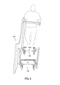
図5に示すように、組み付けたドリー102およびテーブル400は、ドリー102を横にした状態、かつテーブル400の移動ができるように車輪106が床面上に置かれた状態で、テーブル400が側面を下にして、または実質的に側面を下にして置かれるように回転できる。種々の実施形態において、ドリー102をテーブル400に取り付ける作業、その後取り付け位置から移動位置へテーブル400を動かす作業、およびテーブル400の移動作業は1人で行うことができる。さらに、テーブル400が地面に対して90度未満の角度で支持されるため、安定性が向上する。
As shown in FIG. 5, the assembled
このように、種々の実施形態により、より移動しやすく、安定性が向上した状態で、一対の二輪ドリー102でテーブル400等の物体を移動できるシステムが提供される。
As described above, according to various embodiments, a system that can move an object such as the table 400 with the pair of two-
前述の説明はテーブルに関したものであるが、本明細書で説明するドリーはあらゆるタイプの事務用什器、あらゆる一般的な什器、またはあらゆる装置の移動に適していることを理解されたい。ドリー102の高さおよび重さ等のドリー102の構成は、移動対象物体の重さおよび/または高さに応じて変更可能である。
Although the foregoing description relates to a table, it should be understood that the dolly described herein is suitable for the movement of any type of office fixture, any common fixture, or any device. The configuration of the
さらに、本開示は、以下の項による実施形態を含む。 Further, the present disclosure includes embodiments according to the following sections.
項1:移動対象物体にそれぞれ取り付け可能な複数のドリーを備えるシステムであって、ドリーはそれぞれ、第1の端部と第2の端部とを備える基部と、基部の底部に取り付けられる複数の車輪と、基部から上向きに垂直に延伸し、チャネルを形成する側壁と、調節機構と、一方の側壁の内側に沿って配置される係合部材であって、調節機構で圧力をかけた際に変形することでチャネル内で移動対象物体を固定するよう構成される係合部材とを備え、チャネルの内側に、基部の第1の端部に配置され、チャネル内で固定された物体に角度を付けるよう構成されるブロック部材が備えられる、システム。 Item 1: A system including a plurality of dollies that can be attached to a moving object, each of the dollies having a base portion having a first end portion and a second end portion, and a plurality of dollies attached to the bottom portion of the base portion A wheel, a side wall extending vertically upward from the base, and forming a channel; an adjustment mechanism; and an engagement member disposed along the inside of one side wall, when pressure is applied by the adjustment mechanism And an engaging member configured to fix the object to be moved within the channel by deforming, and disposed at the first end of the base on the inside of the channel and at an angle to the object fixed within the channel. A system comprising a block member configured to attach.
項2:基部の長さがチャネルの長さよりも長い、項1に記載のシステム。 Item 2: The system according to Item 1, wherein the length of the base is longer than the length of the channel.
項3:2つのドリーのみを備える、項1または2に記載のシステム。 Item 3: The system according to Item 1 or 2, comprising only two dollies.
項4:複数のドリーが、片持ち状態の構成で移動対象物体に取り付けられる、項1から3のいずれか1つに記載のシステム。 Item 4: The system according to any one of Items 1 to 3, wherein the plurality of dollies are attached to the moving object in a cantilever configuration.
項5:チャネルの幅が約2インチ(5.1センチメートル)から約4インチ(10.2センチメートル)である、項1から4のいずれか1つに記載のシステム。 Item 5: The system of any one of Items 1-4, wherein the channel width is from about 2 inches (5.1 centimeters) to about 4 inches (10.2 centimeters).
項6:調節機構が回転可能なノブを備え、回転可能なノブが作業者によって締められるよう構成される、項1から5のいずれか1つに記載のシステム。 Item 6: The system according to any one of Items 1 to 5, wherein the adjustment mechanism includes a rotatable knob, and the rotatable knob is configured to be tightened by an operator.
項7:複数のドリーが、回転可能なノブを回転して移動対象物体を挟むように係合部材を調節することで、移動対象物体に取り付け可能である、項6に記載のシステム。 Item 7: The system according to Item 6, wherein the plurality of dollies can be attached to the moving target object by adjusting the engaging member so as to sandwich the moving target object by rotating the rotatable knob.
項8:システムはさらに移動対象物体を備え、移動対象物体はテーブルである、項1から7のいずれか1つに記載のシステム。 Item 8: The system according to any one of Items 1 to 7, wherein the system further includes a movement target object, and the movement target object is a table.
項9:複数のドリーはそれぞれテーブルの脚においてテーブルに取り付けられる、項8に記載のシステム。 Item 9: The system according to Item 8, wherein each of the dollies is attached to the table at the table leg.
項10:テーブルが実質的に側面を下にして支持される、項8または9に記載のシステム。 Item 10: The system of item 8 or 9, wherein the table is supported substantially side-down.
項11:側壁の間に配置される緩衝材料をさらに備える、項1から10のいずれか1つに記載のシステム。 Item 11: The system according to any one of Items 1 to 10, further comprising a cushioning material disposed between the side walls.
項12:移動対象物体を搬送する方法であって、方法は、移動対象物体の各延伸部に第1のドリーと第2のドリーとを配置するステップを含み、ドリーはそれぞれ、第1の端部と第2の端部とを備える基部と、基部の底部に取り付けられる車輪と、基部から上向きに垂直に延伸し、チャネルを形成する側壁と、調節機構と、一方の側壁の内側に沿って配置される係合部材とを備え、チャネルの内側に、基部の第1の端部に配置され、移動対象物体に角度を付けるとともに、移動対象物体を片持ち状態で支持するブロック部材が備えられ、複数のドリーがそれぞれ、移動対象物体が据え置き位置に配置された状態で、移動対象物体の各延伸部に配置され、複数のドリーそれぞれの車輪が外向きに配置され、複数のドリーそれぞれが側面を下に配置され、係合部材の変形によりチャネル内で移動対象物体を固定するように調節機構が係合部材に当接するよう、複数のドリーそれぞれに対して調節機構を操作することで、移動対象物体に取り付けるステップを含み、複数のドリーそれぞれのブロック部材が、移動対象物体の各延伸部に接触し、車輪が床面に接触した状態で複数のドリーそれぞれが直立しながら、移動対象物体が側面を下にして配置される位置に移動対象物体を回転するステップを含む、方法。 Item 12: A method for transporting a moving target object, the method including a step of arranging a first dolly and a second dolly in each extension part of the moving target object, each dolly having a first end A base with a portion and a second end, a wheel attached to the bottom of the base, a side wall extending vertically upward from the base to form a channel, an adjustment mechanism, and along the inside of one side wall And a block member that is disposed at the first end of the base portion at an angle inside the channel and that supports the object to be moved in a cantilever state. The plurality of dollies are respectively arranged in the extending portions of the movement target object in a state where the movement target object is arranged at the stationary position, the wheels of each of the plurality of dollies are arranged outwardly, and each of the plurality of dollies is a side surface. Is placed underneath A step of attaching to the moving target object by operating the adjusting mechanism for each of the plurality of dolly so that the adjusting mechanism contacts the engaging member so as to fix the moving target object in the channel by deformation of the joint member. The block members of each of the plurality of dollies are in contact with each extending portion of the object to be moved, and the objects to be moved are arranged with the side faces down while each of the plurality of dollies stands upright with the wheel in contact with the floor surface. Rotating the object to be moved to a position.
項13:移動対象物体に取り付けるステップが、調節機構を時計回りに回転するステップを含む、項12に記載の方法。 Item 13: The method according to Item 12, wherein the step of attaching to the object to be moved includes the step of rotating the adjusting mechanism clockwise.
項14:調節機構を1〜3回完全に回転させるステップをさらに含む、項13に記載の方法。 Item 14: The method according to Item 13, further comprising the step of completely rotating the adjusting mechanism 1 to 3 times.
項15:移動対象物体の延伸部が脚の一部であり、移動対象物体がテーブルである、項12から14のいずれか1つに記載の方法。 Item 15: The method according to any one of Items 12 to 14, wherein the extension part of the moving target object is a part of a leg, and the moving target object is a table.
項16:車輪が、ロック可能であり、移動対象物体の回転中にロック位置に配置されるキャスタの一部を形成する、項12から15のいずれか1つに記載の方法。 Item 16: The method according to any one of Items 12 to 15, wherein the wheel is lockable and forms part of a caster that is placed in a locked position during rotation of the object to be moved.
項17:移動対象物体を回転した後、移動対象物体を第1の位置から第2の位置へ搬送するステップをさらに含み、移動中、キャスタがロック解除位置にある、項16に記載の方法。 Item 17: The method according to Item 16, further comprising the step of conveying the movement target object from the first position to the second position after rotating the movement target object, wherein the caster is in the unlocked position during the movement.
項18:2つの側板の間に防振材を設けるステップをさらに含む、項12から17のいずれか1つに記載の方法。 Item 18: The method according to any one of Items 12 to 17, further comprising the step of providing an anti-vibration material between the two side plates.
項19:2つの位置に配置される調節可能な圧力板を備えるドリーであって、一方の位置はテーブルの脚にドリーを固定するためのものであり、他方の位置はドリーからテーブルを離すためのものであり、ドリーは、実質的に側面を下にし、搬送中にテーブルが転倒する尤度を減らすため片持ち状態でテーブルを支持するよう構成される、ドリー。 Item 19: A dolly with adjustable pressure plates placed in two positions, one position for fixing the dolly to the table leg and the other position for separating the table from the dolly And the dolly is configured to support the table in a cantilevered state to reduce the likelihood that the table will tip over during transport substantially side down.
項20:ドリーのチャネル内で固定されたテーブルに角度を付けるようにドリーの一方の端部に配置されるブロック部材をさらに備える、項19に記載のドリー。 Item 20: The dolly according to item 19, further comprising a block member disposed at one end of the dolly so as to angle the table fixed in the channel of the dolly.
本明細書に開示された装置および方法の様々な例および実施態様は、様々な部品、特徴、および機能を有する。本明細書に開示された装置および方法の様々な例および実施態様は、本明細書に開示された装置および方法の他の例および実施態様における部品、特徴、および機能を、どのような組み合わせで有しても良く、かかる可能性は全て、本開示の趣旨および範囲に含まれるものであることを理解されたい。 Various examples and embodiments of the devices and methods disclosed herein have various parts, features, and functions. Various examples and implementations of the devices and methods disclosed herein can be used in any combination of components, features, and functions in other examples and implementations of the devices and methods disclosed herein. It should be understood that all such possibilities are within the spirit and scope of this disclosure.
上述の説明は例示的であることを意図したものであり、限定を意図するものではないことを理解されたい。例えば、上述の実施形態(および/またはその実施態様)は互いに組み合わせて使用してもよい。また、特定の状況または材料について、種々の実施形態の教示事項にそれらの範囲から逸脱せずに適合するように、多数の修正を行ってもよい。本明細書で説明した材料の大きさとタイプは種々の実施形態のパラメータを定義することを意図したものであるが、当該実施形態は決して限定的なものではなく、例示的な実施形態である。多数の他の実施形態は、上述の説明を検討すれば当業者には明らかであろう。種々の実施形態の範囲は、したがって、添付の諸請求項を参照して、かかる請求項が権利を与える均等物の全範囲に沿って、決定されるべきである。 It should be understood that the above description is intended to be illustrative and not limiting. For example, the above-described embodiments (and / or implementations thereof) may be used in combination with each other. In addition, many modifications may be made to adapt a particular situation or material to the teachings of various embodiments without departing from their scope. While the material sizes and types described herein are intended to define parameters for various embodiments, the embodiments are by no means limiting and are exemplary embodiments. Many other embodiments will be apparent to those of skill in the art upon reviewing the above description. The scope of various embodiments should, therefore, be determined with reference to the appended claims, along with the full scope of equivalents to which such claims are entitled.
本明細書で使用する際、「システム」、「サブシステム」、「ユニット」、または「モジュール」という用語は、1つ以上の機能を実行するために動作するハードウェアのあらゆる組み合わせを含み得る。よって、例えば、1つ以上の部品が単一のハードウェア、または複数のハードウェアに実装されてもよい。種々の実施形態は図示の配置および手段に限定されないことを理解されたい。 As used herein, the term “system”, “subsystem”, “unit”, or “module” may include any combination of hardware that operates to perform one or more functions. Thus, for example, one or more components may be mounted on a single hardware or a plurality of hardware. It should be understood that the various embodiments are not limited to the arrangements and instrumentality shown.
本明細書で使用する際、単数形で記載され単語「a」または「an」が先行する要素またはステップは、排除の旨が明確に述べられていない限り、複数の前記要素またはステップを排除しないと理解されるべきである。さらに、「一実施形態」との言及は、記載した特徴を取り込む追加の実施形態の存在を排除すると解釈されるとは意図していない。さらに、特に断らない限り、特定の特性を有する要素または複数の要素を「含む」かまたは「有する」実施形態が、その特性を有さない追加の要素を含んでもよい。 As used herein, an element or step described in the singular and preceded by the word “a” or “an” does not exclude a plurality of such elements or steps, unless expressly stated to the contrary. Should be understood. Furthermore, references to “one embodiment” are not intended to be interpreted as excluding the existence of additional embodiments that also incorporate the recited features. Further, unless specifically stated otherwise, embodiments that “include” or “have” an element or elements having a particular characteristic may include additional elements that do not have that characteristic.
添付の特許請求の範囲では、「including」および「in which」という用語は、「comprising」および「wherein」という各用語の平易な英語の均等物として使用される。さらに、添付の請求項において、「第1の」、「第2の」、および「第3の」等という用語はラベルとして使用されるにすぎず、その対象物に対する数値的な要件を課すことを意図したものではない。さらに、添付の請求項の限定はミーンズ・プラス・ファンクション形式では記載されておらず、かかる請求項の限定が明示的に「means for」のフレーズを使用した後にさらなる構造が欠如した機能の記述を使用しない限り、またはそうされるまで、米国特許法第112条(f)に基づいて解釈されることを意図したものではない。 In the appended claims, the terms “including” and “in which” are used as plain English equivalents for the terms “comprising” and “wherein”. Furthermore, in the appended claims, the terms “first”, “second”, “third”, etc. are only used as labels and impose numerical requirements on the object. Is not intended. In addition, the limitations of the appended claims are not stated in means-plus-function format, and such claims should be explicitly described using the phrase “means for” to describe a function that lacks further structure. It is not intended to be construed under 35 USC 112 (f) unless used or until so.
記載した説明では、ベスト・モードを含む種々の実施形態を開示し、任意の器具またはシステムを生成し使用することおよび任意の取り込まれた方法を実施することを含めて、当業者が種々の実施形態を実施できるようにするための例を使用している。種々の実施形態の特許可能な範囲は、特許請求の範囲により定義され、当業者が想到する他の例を含んでもよい。かかる他の例は、それらが諸請求項の文言と相違しない構造的要素を有する場合、または、それらが諸請求項の文言と実質的に相違しない均等な構造的要素を含む場合に、諸請求項の範囲内にあるものである。 The written description discloses various embodiments, including the best mode, and allows those skilled in the art to perform various implementations, including generating and using any instrument or system and implementing any incorporated method. An example is used to allow the form to be implemented. The patentable scope of the various embodiments is defined by the claims, and may include other examples that occur to those skilled in the art. Such other examples are claimed when they have structural elements that do not differ from the language of the claims, or when they contain equivalent structural elements that do not substantially differ from the language of the claims. Is within the scope of the term.
100 移動システム
102 ドリー
104 基部
106 車輪
107 キャスタ
108 側面
110A、110B 側壁
112 上部
114 チャネル
116 係合部材
118 調節機構
120 長手方向端部
200 空隙
202 ブロック部材
250 緩衝材料、防振材
400 テーブル
402 脚
404 延伸部
406 据え置き部
100 moving system
102 Dolly
104 base
106 wheels
107 Casters
108 sides
110A, 110B side wall
112 Top
114 channels
116 engaging member
118 Adjustment mechanism
120 Longitudinal edge
200 gap
202 Block member
250 cushioning material, anti-vibration material
400 tables
402 legs
404 Stretching part
406 Deferred section
Claims (31)
第1の端部と第2の端部とを備える基部と、
前記基部の底部に取り付けられる複数の車輪と、
前記基部から上向きに垂直に延伸し、チャネルを形成する側壁と、
調節機構と、
一方の前記側壁の内側に沿って配置される係合部材であって、前記調節機構で圧力をかけた際に変形することで前記チャネル内で前記移動対象物体を固定するよう構成される係合部材と
を備え、
前記チャネルの内側に、前記基部の前記第1の端部に配置されかつ前記チャネル内で固定された前記物体に角度を付けるよう構成されたブロック部材が設けられるドリー。 A dolly that can be attached to a moving object ,
A base comprising a first end and a second end;
A plurality of wheels attached to the bottom of the base;
A sidewall extending vertically upward from the base and forming a channel;
An adjustment mechanism;
An engagement member disposed along the inner side of one of the side walls, the engagement member configured to fix the object to be moved in the channel by being deformed when pressure is applied by the adjustment mechanism. A member and
The inside of the channel, Dolly said first located at the end and configured block member so as to give a fixed angle to the object was in the channel of the base is provided.
前記方法は、移動対象物体の各延伸部に第1のドリーと第2のドリーとを配置するステップを含み、
前記ドリーはそれぞれ、
第1の端部と第2の端部とを備える基部と、
前記基部の底部に取り付けられる車輪と、
前記基部から上向きに垂直に延伸し、チャネルを形成する側壁と、
調節機構と、
一方の前記側壁の内側に沿って配置される係合部材と
を備え、
前記チャネルの内側に、前記基部の前記第1の端部に配置され、前記移動対象物体に角度を付けるとともに、前記移動対象物体を片持ち状態で支持するブロック部材が備えられ、
前記複数のドリーがそれぞれ、前記移動対象物体が据え置き位置に配置された状態で、前記移動対象物体の前記各延伸部に配置され、前記複数のドリーそれぞれの前記車輪が外向きに配置され、前記複数のドリーそれぞれが側面を下に配置され、
前記係合部材の変形により前記チャネル内で前記移動対象物体を固定するように前記調節機構が前記係合部材に当接するよう、前記複数のドリーそれぞれに対して前記調節機構を操作することで、前記移動対象物体に取り付けるステップを含み、
前記複数のドリーそれぞれの前記ブロック部材が、前記移動対象物体の前記各延伸部に接触し、
前記車輪が床面に接触した状態で前記複数のドリーそれぞれが直立しながら、前記移動対象物体が側面を下にして配置される位置に前記移動対象物体を回転するステップを含む、方法。 A method for transporting a moving object,
The method includes the steps of disposing a first dolly and a second dolly at each extending portion of the object to be moved,
Each dolly is
A base comprising a first end and a second end;
A wheel attached to the bottom of the base;
A sidewall extending vertically upward from the base and forming a channel;
An adjustment mechanism;
An engagement member disposed along the inside of the one side wall,
Inside the channel, disposed at the first end of the base, and provided with a block member that supports the moving target object in a cantilevered state while providing an angle to the moving target object,
Each of the plurality of dollies is disposed in each extending portion of the movement target object in a state where the movement target object is disposed at a stationary position, and the wheels of each of the plurality of dollies are disposed outward. Each of the multiple dollies is arranged with the side down,
By operating the adjustment mechanism with respect to each of the plurality of dolly so that the adjustment mechanism abuts on the engagement member so as to fix the object to be moved in the channel by deformation of the engagement member, Attaching to the object to be moved,
The block members of each of the plurality of dollies are in contact with the extending portions of the object to be moved;
The method includes the step of rotating the moving target object to a position where the moving target object is disposed with the side face down while each of the plurality of dollies stands upright with the wheel in contact with a floor surface.
Applications Claiming Priority (2)
| Application Number | Priority Date | Filing Date | Title |
|---|---|---|---|
| US15/087,608 US10150494B2 (en) | 2016-03-31 | 2016-03-31 | System and method for transporting an object to be moved |
| US15/087,608 | 2016-03-31 |
Publications (3)
| Publication Number | Publication Date |
|---|---|
| JP2017185990A JP2017185990A (en) | 2017-10-12 |
| JP2017185990A5 JP2017185990A5 (en) | 2018-10-25 |
| JP6431890B2 true JP6431890B2 (en) | 2018-11-28 |
Family
ID=58687861
Family Applications (1)
| Application Number | Title | Priority Date | Filing Date |
|---|---|---|---|
| JP2016244123A Active JP6431890B2 (en) | 2016-03-31 | 2016-12-16 | System and method for conveying a moving object |
Country Status (3)
| Country | Link |
|---|---|
| US (1) | US10150494B2 (en) |
| JP (1) | JP6431890B2 (en) |
| GB (1) | GB2550272B (en) |
Families Citing this family (8)
| Publication number | Priority date | Publication date | Assignee | Title |
|---|---|---|---|---|
| US9969416B2 (en) * | 2016-08-18 | 2018-05-15 | Patrick M. Tarrant | Scaffold storage and transportation dolly set |
| US11197551B2 (en) * | 2019-11-08 | 2021-12-14 | The Boeing Company | Seat transit systems and methods |
| US11453427B2 (en) * | 2020-03-27 | 2022-09-27 | Telefonaktiebolaget Lm Ericsson (Publ) | Handling device for transporting components of a checkout station |
| US11673594B2 (en) * | 2021-04-22 | 2023-06-13 | Daniel B. Goetsch | Swing caster dolly |
| USD1002143S1 (en) * | 2022-03-31 | 2023-10-17 | Feng Cheng | Roller trolley assembly |
| US11767048B1 (en) * | 2022-04-19 | 2023-09-26 | Roger Crowley | Support strut |
| US20230415801A1 (en) * | 2022-06-22 | 2023-12-28 | Carl Lauver | Lift System and Method for Moving a Metal Frame Cabinet |
| USD1001409S1 (en) * | 2023-06-29 | 2023-10-10 | Jingjing Li | Wheel for a cargo lift |
Family Cites Families (32)
| Publication number | Priority date | Publication date | Assignee | Title |
|---|---|---|---|---|
| US2733929A (en) * | 1956-02-07 | edixon | ||
| US1738096A (en) * | 1927-12-20 | 1929-12-03 | Perino B Cole | Barrel truck |
| US3338591A (en) * | 1965-08-17 | 1967-08-29 | David L Rowland | Dolly for stacking chairs |
| US3327996A (en) * | 1965-11-15 | 1967-06-27 | Carl W Morse | Lift device for counters and the like |
| US3684110A (en) * | 1970-11-12 | 1972-08-15 | Meyercord Ind Inc | Tilt dolly |
| US3942813A (en) * | 1975-02-12 | 1976-03-09 | Dombroski Bernard F | Apparatus for facilitating movement of furniture |
| US4178006A (en) * | 1978-02-21 | 1979-12-11 | Johnson Richard E | Furniture dolly |
| US4210341A (en) * | 1978-03-24 | 1980-07-01 | William Minkoff | Transport apparatus |
| US4852895A (en) | 1988-04-14 | 1989-08-01 | Don Moffitt | Dolly |
| US5486014A (en) * | 1994-03-08 | 1996-01-23 | Hough; Darald F. | Dolly having elongated channel with releasable frictional securement device |
| US5788251A (en) | 1994-07-12 | 1998-08-04 | Johnson; Rudolph O. | Table lift and transporter |
| US5927731A (en) * | 1996-08-28 | 1999-07-27 | Clarke; John P. | Door trolley |
| US5822829A (en) * | 1997-04-01 | 1998-10-20 | Webb Equipment Company, Inc. | Caster assembly for moving storage rack components |
| US5879014A (en) * | 1997-08-11 | 1999-03-09 | Price; Gary A | Adjustable dolly |
| US6250655B1 (en) * | 1999-05-07 | 2001-06-26 | Oliver Perry Sheeks | Leveraging transport system for tables plasterboard sheets and the like |
| US6575481B1 (en) * | 1999-05-07 | 2003-06-10 | Jeffrey L. Davis | Picnic table dolly and method therefor |
| US6231034B1 (en) | 1999-10-27 | 2001-05-15 | Michael R. Walker | Door mounting apparatus |
| US6505844B2 (en) | 2001-02-16 | 2003-01-14 | David Hallman | Door transporting and support system |
| DE10203426A1 (en) * | 2002-01-28 | 2003-08-14 | Wizorek Mathias | Lifting and transport unit, in particular, for door systems comprises a wheel-mounted main frame which has an adjustable height and is provided with at least one clamping device |
| US7311487B1 (en) * | 2004-10-29 | 2007-12-25 | Eric Crossley | Apparatus and method for repositioning warehouse shelving units |
| GB2424668A (en) | 2005-03-30 | 2006-10-04 | Damion Wilcox | Wheeled door stabiliser |
| US20060232034A1 (en) | 2005-04-19 | 2006-10-19 | Skiles Charles T | Furniture cart |
| ATE464221T1 (en) * | 2005-09-05 | 2010-04-15 | Checkmate Internat Pty Ltd | DEVICE FOR TRANSPORTING PRODUCTS IN BOXES OR CONTAINERS |
| US8002293B2 (en) * | 2007-03-07 | 2011-08-23 | The Durham Manufacturing Company | Material handling apparatus and support therefor |
| JP3137180U (en) * | 2007-09-04 | 2007-11-15 | 哲 茨野 | Heavy goods cart |
| SE533740C2 (en) * | 2009-05-13 | 2010-12-21 | Peder Jensen | Device and method of transporting goods |
| US8348287B1 (en) * | 2009-11-30 | 2013-01-08 | Smith Phillip J | Slab cart |
| US8641061B1 (en) * | 2009-12-02 | 2014-02-04 | Dale W. Sims | Collapsible, transportable cart for building materials |
| GB2491898B (en) * | 2011-06-17 | 2014-11-19 | William John Mcguckin | A coffin transporter |
| US20140097585A1 (en) | 2012-10-05 | 2014-04-10 | Michael Dallas Baird | DK3D Dolly |
| US9061697B2 (en) * | 2013-04-09 | 2015-06-23 | Daniel Lee Veronie | Transportation dollies |
| USD776392S1 (en) * | 2015-04-23 | 2017-01-10 | David Prichard | Carrier lift for plumbing |
-
2016
- 2016-03-31 US US15/087,608 patent/US10150494B2/en active Active
- 2016-12-16 JP JP2016244123A patent/JP6431890B2/en active Active
-
2017
- 2017-03-24 GB GB1704665.7A patent/GB2550272B/en active Active
Also Published As
| Publication number | Publication date |
|---|---|
| US10150494B2 (en) | 2018-12-11 |
| GB2550272A (en) | 2017-11-15 |
| JP2017185990A (en) | 2017-10-12 |
| GB2550272B (en) | 2018-09-26 |
| GB201704665D0 (en) | 2017-05-10 |
| US20170282778A1 (en) | 2017-10-05 |
Similar Documents
| Publication | Publication Date | Title |
|---|---|---|
| JP6431890B2 (en) | System and method for conveying a moving object | |
| US10327544B2 (en) | Adjustable ergonomic workstation | |
| US20150196140A1 (en) | Adjustable device holder | |
| US9933106B2 (en) | Height adjustable support | |
| US7314248B2 (en) | Portable workstation | |
| JP4241394B2 (en) | Tripod and its usage | |
| US7828253B2 (en) | Secure shelf for technology workstand | |
| US7762566B2 (en) | Computer cart | |
| JP2017185990A5 (en) | ||
| US10918453B2 (en) | Portable monitoring system transport case | |
| US10869976B2 (en) | Ventilator mount system | |
| US8104753B2 (en) | Support means | |
| US8973938B2 (en) | Universal foot tray for wheelchairs | |
| KR101504724B1 (en) | Delivery cart | |
| US8844948B1 (en) | Shopping cart crutch assembly | |
| US6719307B1 (en) | Sideboard system for a camera dolly | |
| JP2015206681A (en) | Scale | |
| US9365226B1 (en) | Transport dolly | |
| JP3142003U (en) | Vibration control device | |
| US20160262585A1 (en) | Portable Frame and Toilet System | |
| US20040026582A1 (en) | Equipment support for use with office cubicles | |
| US20240001978A1 (en) | Foldable Transport Cart For Planar Materials | |
| JP2012158974A (en) | Wheel stop device | |
| JP6369186B2 (en) | Transport fixture | |
| US11370142B2 (en) | Wheeled saw support apparatus |
Legal Events
| Date | Code | Title | Description |
|---|---|---|---|
| A521 | Request for written amendment filed |
Free format text: JAPANESE INTERMEDIATE CODE: A523 Effective date: 20180912 |
|
| A621 | Written request for application examination |
Free format text: JAPANESE INTERMEDIATE CODE: A621 Effective date: 20180912 |
|
| A871 | Explanation of circumstances concerning accelerated examination |
Free format text: JAPANESE INTERMEDIATE CODE: A871 Effective date: 20180912 |
|
| A975 | Report on accelerated examination |
Free format text: JAPANESE INTERMEDIATE CODE: A971005 Effective date: 20181002 |
|
| TRDD | Decision of grant or rejection written | ||
| A01 | Written decision to grant a patent or to grant a registration (utility model) |
Free format text: JAPANESE INTERMEDIATE CODE: A01 Effective date: 20181005 |
|
| A61 | First payment of annual fees (during grant procedure) |
Free format text: JAPANESE INTERMEDIATE CODE: A61 Effective date: 20181105 |
|
| R150 | Certificate of patent or registration of utility model |
Ref document number: 6431890 Country of ref document: JP Free format text: JAPANESE INTERMEDIATE CODE: R150 |
|
| R250 | Receipt of annual fees |
Free format text: JAPANESE INTERMEDIATE CODE: R250 |
|
| R250 | Receipt of annual fees |
Free format text: JAPANESE INTERMEDIATE CODE: R250 |
|
| R250 | Receipt of annual fees |
Free format text: JAPANESE INTERMEDIATE CODE: R250 |